EP3388162B1 - Operating unit for a profiling line - Google Patents
Operating unit for a profiling line Download PDFInfo
- Publication number
- EP3388162B1 EP3388162B1 EP18157664.6A EP18157664A EP3388162B1 EP 3388162 B1 EP3388162 B1 EP 3388162B1 EP 18157664 A EP18157664 A EP 18157664A EP 3388162 B1 EP3388162 B1 EP 3388162B1
- Authority
- EP
- European Patent Office
- Prior art keywords
- operating unit
- profiled element
- contact
- rollers
- conical portion
- Prior art date
- Legal status (The legal status is an assumption and is not a legal conclusion. Google has not performed a legal analysis and makes no representation as to the accuracy of the status listed.)
- Active
Links
- 238000000034 method Methods 0.000 claims description 8
- 238000005452 bending Methods 0.000 description 8
- 230000007423 decrease Effects 0.000 description 3
- 238000004519 manufacturing process Methods 0.000 description 3
- 238000003466 welding Methods 0.000 description 3
- 238000006073 displacement reaction Methods 0.000 description 2
- 230000000750 progressive effect Effects 0.000 description 2
- 229910000831 Steel Inorganic materials 0.000 description 1
- 230000003213 activating effect Effects 0.000 description 1
- 238000006243 chemical reaction Methods 0.000 description 1
- 230000006698 induction Effects 0.000 description 1
- 238000003754 machining Methods 0.000 description 1
- 239000007787 solid Substances 0.000 description 1
- 239000010959 steel Substances 0.000 description 1
Images


Classifications
-
- B—PERFORMING OPERATIONS; TRANSPORTING
- B21—MECHANICAL METAL-WORKING WITHOUT ESSENTIALLY REMOVING MATERIAL; PUNCHING METAL
- B21D—WORKING OR PROCESSING OF SHEET METAL OR METAL TUBES, RODS OR PROFILES WITHOUT ESSENTIALLY REMOVING MATERIAL; PUNCHING METAL
- B21D5/00—Bending sheet metal along straight lines, e.g. to form simple curves
- B21D5/06—Bending sheet metal along straight lines, e.g. to form simple curves by drawing procedure making use of dies or forming-rollers, e.g. making profiles
- B21D5/08—Bending sheet metal along straight lines, e.g. to form simple curves by drawing procedure making use of dies or forming-rollers, e.g. making profiles making use of forming-rollers
-
- B—PERFORMING OPERATIONS; TRANSPORTING
- B21—MECHANICAL METAL-WORKING WITHOUT ESSENTIALLY REMOVING MATERIAL; PUNCHING METAL
- B21B—ROLLING OF METAL
- B21B27/00—Rolls, roll alloys or roll fabrication; Lubricating, cooling or heating rolls while in use
- B21B27/02—Shape or construction of rolls
- B21B27/028—Variable-width rolls
-
- B—PERFORMING OPERATIONS; TRANSPORTING
- B21—MECHANICAL METAL-WORKING WITHOUT ESSENTIALLY REMOVING MATERIAL; PUNCHING METAL
- B21B—ROLLING OF METAL
- B21B1/00—Metal-rolling methods or mills for making semi-finished products of solid or profiled cross-section; Sequence of operations in milling trains; Layout of rolling-mill plant, e.g. grouping of stands; Succession of passes or of sectional pass alternations
- B21B1/22—Metal-rolling methods or mills for making semi-finished products of solid or profiled cross-section; Sequence of operations in milling trains; Layout of rolling-mill plant, e.g. grouping of stands; Succession of passes or of sectional pass alternations for rolling plates, strips, bands or sheets of indefinite length
- B21B1/24—Metal-rolling methods or mills for making semi-finished products of solid or profiled cross-section; Sequence of operations in milling trains; Layout of rolling-mill plant, e.g. grouping of stands; Succession of passes or of sectional pass alternations for rolling plates, strips, bands or sheets of indefinite length in a continuous or semi-continuous process
-
- B—PERFORMING OPERATIONS; TRANSPORTING
- B21—MECHANICAL METAL-WORKING WITHOUT ESSENTIALLY REMOVING MATERIAL; PUNCHING METAL
- B21B—ROLLING OF METAL
- B21B13/00—Metal-rolling stands, i.e. an assembly composed of a stand frame, rolls, and accessories
- B21B13/08—Metal-rolling stands, i.e. an assembly composed of a stand frame, rolls, and accessories with differently-directed roll axes, e.g. for the so-called "universal" rolling process
- B21B13/10—Metal-rolling stands, i.e. an assembly composed of a stand frame, rolls, and accessories with differently-directed roll axes, e.g. for the so-called "universal" rolling process all axes being arranged in one plane
- B21B13/103—Metal-rolling stands, i.e. an assembly composed of a stand frame, rolls, and accessories with differently-directed roll axes, e.g. for the so-called "universal" rolling process all axes being arranged in one plane for rolling bars, rods or wire
-
- B—PERFORMING OPERATIONS; TRANSPORTING
- B21—MECHANICAL METAL-WORKING WITHOUT ESSENTIALLY REMOVING MATERIAL; PUNCHING METAL
- B21B—ROLLING OF METAL
- B21B27/00—Rolls, roll alloys or roll fabrication; Lubricating, cooling or heating rolls while in use
- B21B27/02—Shape or construction of rolls
- B21B27/024—Rolls for bars, rods, rounds, tubes, wire or the like
-
- B—PERFORMING OPERATIONS; TRANSPORTING
- B21—MECHANICAL METAL-WORKING WITHOUT ESSENTIALLY REMOVING MATERIAL; PUNCHING METAL
- B21D—WORKING OR PROCESSING OF SHEET METAL OR METAL TUBES, RODS OR PROFILES WITHOUT ESSENTIALLY REMOVING MATERIAL; PUNCHING METAL
- B21D5/00—Bending sheet metal along straight lines, e.g. to form simple curves
- B21D5/06—Bending sheet metal along straight lines, e.g. to form simple curves by drawing procedure making use of dies or forming-rollers, e.g. making profiles
- B21D5/08—Bending sheet metal along straight lines, e.g. to form simple curves by drawing procedure making use of dies or forming-rollers, e.g. making profiles making use of forming-rollers
- B21D5/086—Bending sheet metal along straight lines, e.g. to form simple curves by drawing procedure making use of dies or forming-rollers, e.g. making profiles making use of forming-rollers for obtaining closed hollow profiles
Definitions
- the present invention relates to an operating unit for a profiling line and to a method for profiling a profiled element according to the preambles of claims 1 and 9.
- Such an operating unit and such a method are for example disclosed in JP-A-2003251413 .
- the invention relates to an operating unit having shaped rollers for profiling lines for tubes having a polygonal section, for example rectangular or square.
- a profiling line allows a tubular profiled element to be produced starting from a steel strip which is progressively bent back in line about a longitudinal axis thereof until it assumes a tubular conformation wherein the longitudinal edges of the strip are arranged alongside one another in the upper zone of the profiled element.
- a profiling line substantially comprises a series of bending units, arranged in succession, each of which comprises two or more profiling rollers. The progressive bending of the profiled element takes place by making the strip pass through the rollers of the various bending units which, by contact, progressively deform it. The strip slides continuously through the bending units, being progressively deformed.
- the longitudinal edges are welded together.
- the profiled element is subsequently cut into portions of a pre-established length, according to known processes.
- the whole production is performed in line, i.e. while the profiled element is continuously advancing.
- the bending of the strip initially takes place by the operation of rollers that are located at the points in which the corners of the profiled element are to be realised.
- rollers are positioned above and below the strip, at the corners that will progressively form.
- On the lower or external side of the strip rotating rollers are positioned which exert an opposite pressure to the pressure exerted by the discs.
- Discs and rollers are aligned in succession along the longitudinal axis of the strip, supported by a support structure which can assume various configurations.
- a progressive bending is achieved about the longitudinal axis, up to obtaining a profiled element that is closed and tube-shaped.
- the closing of the tube takes place in a terminal portion of the line, along which the two opposite edges of the strip are brought side-by-side with one another and then welded in line, for example by induction or high-frequency welding, in a known way in the sector.
- the terminal portion of the line which produces the closing of the profiled element generally comprises a plurality of rollers, arranged outside the profiled element.
- the rollers are positioned outside the profiled element as, physically, a sufficient space is not available to enable an internal location of sufficiently sturdy rollers.
- the orientation of the various rollers, which can be adjustable, varies progressively along the terminal portion of the line, for progressively guiding the profiled element to the closing step.
- the profiled element reaches such terminal portion when it has a substantially U-shaped bent section defined by a horizontal lower side, two sides that diverge from one another in an upwards direction, and two upper sides inclined upward so as to be converging towards each other.
- the two upper sides are destined to flank one another in a horizontal position, to define the upper side of the section.
- each cage generally comprises a lower roller, with a horizontal rotating axis, two lateral rollers, with rotating axes parallel to the sides of the profiled elements and diverging from one another in an upwards direction, and two upper rollers, which can be conical or cylindrical; in the last case with the rotating axes converging to each other in an upwards direction.
- the rotating axes of the lateral rollers of the various cages progressively incline towards a vertical direction.
- the rotating axes of the various upper rollers, or the taper thereof in a case where they are realised in a conical form, progressively incline towards a horizontal direction.
- each cage must be provided with complex adjustment devices, which enable varying the inclination and the position of the rollers at least on a vertical plane.
- the activating of these adjustment devices can be considerably laborious, and often requires the use of complex set-up software.
- rollers at present used, associated to the respective cages often do not realise a correct closure of the profiled element.
- the two upper sides are not always arranged perfectly coplanarly, with the edges perfectly flanked to one another, so that it is necessary to perform very accurate adjustments of the positions of the various rollers.
- rollers at present used do not enable precisely realising the fillet radii required between the sides of the profiled element. This is because, during the closing step of the profiled element, the upper edges of the profiled element can slide in an undesired way on the surfaces of the upper rollers.
- the object of the present invention is to disclose an operating unit for a profiling line and a method for profiling which enables obviating the drawbacks summarised.
- An advantage of the operating unit according to the present invention is that it facilitates the correct closing of the profiled element, drastically reducing the need to adjust the position of the various rollers.
- Another advantage of the operating unit according to the present invention is that it enables very precisely obtaining the fillet radii required between the various sides of the profiled element.
- a further advantage of the operating unit according to the present invention is that it significantly prevents or limits any tendency of the profiled element to twist about the longitudinal axis thereof.
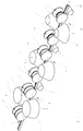
- Figure 3 schematically illustrates a portion of the finishing portion of a profiling line.
- three operating units (M) are illustrated, each provided with two shaped rollers (1) according to the present invention.
- the operating units (M) are aligned along a longitudinal direction (Y) which also defines the longitudinal axis of the profiled element (P).
- the profiled element (P) that enters each operating unit presents, on a section carried out with a plane perpendicular to the longitudinal direction (Y), a lower side (B), two sides (S1, S2) and two upper sides (T1, T2) inclined upward so as to be converging towards each other ( figure 2 ).
- the lower side (B) is substantially horizontal.
- the sides (S1, S2) can be divergent in an upwards direction, as in the represented case. Proceeding progressively along the finishing portion through the various operating units, the sides (S1, S2) assume a position progressively closer to the vertical axis, while the upper sides progressively approach a horizontal position.
- the shaped roller of the operating unit comprises a conical portion (2) and an end portion (3), concentric with respect to a rotating axis (Z).
- the rotating axis (Z) is preferably though not necessarily horizontal and is perpendicular to the longitudinal direction (Y).
- the conical portion (2) is provided with a vertex section (23), in which the diameter is minimal.
- the end portion (3) has a greater diameter than the vertex section (23). In this way, the end portion (3) defines a shoulder from the surface of the first conical portion (2).
- the conformation of the shaped roller (1) of the operating unit according to the present invention provides important advantages.
- the conical portion (2) is predisposed to enter into contact with an upper side (T1) of the profiled element.
- T1 As it enters into contact with the conical portion (2), such upper side (T1) assumes an inclination that is substantially coincident with the taper of the conical portion (2).
- the shaped rollers of the operating unit according to the present invention can be arranged with the rotating axis horizontal.
- the end portion (3) provided with a greater diameter with respect to the vertex section (23), defines a shoulder in contact with which the edge of the upper side (T1) is positioned, as schematically illustrated in figure 1 .
- the upper side (T1) does not slide on the surface of the conical portion (2) and can be bent thereby with a high degree of precision, enabling predetermined fillet radii to be realised with the side (S1).
- the shaped rollers (1) of the various operating units have a taper that gradually decreases in the advancement direction of the profiled element, up to reaching a very small taper or becoming substantially cylindrical so as to bring the upper sides (T1, T2) into a position that is very close to a horizontal position.
- a welding group that, by means of an upper cylindrical roller or other means, makes the upper sides (T1, T2) substantially horizontal and ready for the subsequent welding.
- the end portion (3) is preferably though not necessarily conical and is connected to the conical portion (2) at the vertex section (23).
- the conical conformation of the end portion (3), the inclination of which, with respect to the rotating axis (Z), is opposite with respect to that of the conical portion (2) enables reducing the peaks of pressure which can occur at the vertex section (23) and at the edge of the upper side (T1).
- the conical conformation of the end portion (3) facilitates overall the machining of the surface of the roller.
- the angle included between the tapers of the conical portion (2) and of the end portion (3) is preferably but not necessarily greater than or equal to a right angle. This enables obtaining the advantages connected with the conical conformation of the end portion (3), maintaining a solid rest for the edge of the upper side (T1).
- the shaped roller has shoulders (21, 31), i.e. zones located at the ends of the roller, having a cylindrical shape.
- the operating unit according to the present invention comprises two shaped rollers (1), positioned with the end portions (3) thereof facing each other, i.e. positioned with the end portions facing towards the longitudinal direction (Y) and towards a vertical plane containing the longitudinal direction (Y).
- the two shaped rollers (1) have the rotating axes (Z) thereof aligned. This solution enables reducing the dimensions of the operating unit along the longitudinal axis (Y).
- the shaped rollers (1) are arranged so that the upper sides (T1, T2) of the profiled element are in contact with the conical portion (2). As already mentioned, as they enter into contact with the conical portion (2) of the rollers (1), the upper sides (T1, T2) assume an inclination that is substantially coincident with the taper of the conical portion (2). As already mentioned, the shaped rollers (1) of the various operating units have a taper that gradually decreases in the advancement direction of the profiled element, so as to bring the upper sides (T1, T2) in a position progressively closer to the horizontal position.
- the operating unit can be provided with adjustment means to allow the movement of the shaped rollers (1) along one or more horizontal directions and/or along a vertical direction.
- the adjustment means can enable the nearing or distancing of the rollers (1) along a horizontal direction parallel to the rotating axes and/or a displacement of the rollers (1) along a direction parallel to the longitudinal axis (Y).
- the adjustment means are not illustrated in greater detail as they are known to a person skilled in the sector.
- the possibility of adjusting the position of the shaped rollers (1) enables varying the shape and section of the profiled element (P), and varying the progression of the bending of the profiled element (P).
- the operating unit (M) can be further provided with a lower roller (11), arranged to come into contact with the lower side (B) of the profiled element.
- the lower roller (11) is inclined in accordance with the inclination that it is desired to obtain for the lower side (B) of the profiled element.
- the lower roller (11) is cylindrical and is arranged with the rotating axis horizontal.
- Adjustment means can be predisposed to enable the movement of the lower roller (11) along one or more horizontal directions and/or along a vertical direction, in order to enable various sections of the profiled element (P) to be obtained.
- the adjustment means are not illustrated in greater detail as they are known to a person skilled in the sector.
- a lower roller (11) is interposed between two consecutive operating units (M).
- the operating unit (M) can further comprise a pair of lateral rollers (12, 13), arranged to come into contact with the sides (S1, S2) of the profiled element.
- the lateral rollers (12, 13) can have a conical or cylindrical conformation (respectively figures 4 and 5 ); in the latter case with an inclinable and adjustable rotating axis. As they enter into contact with the surface of the lateral rollers (12, 13), the sides (S1, S2) assume an inclination that substantially coincides with the taper of the lateral rollers (12, 13), in the first case, or substantially coincides with the inclination of the lateral rollers (12, 13) in the second case.
- each end portion (3) defines a reaction point for the edge of an upper side (T1, T2), which cannot therefore slide on the conical surface of the roller.
- T1, T2 upper side
- the lateral rollers (12,13) to press on the sides (S1, S2) in a uniform manner, given that the sides (S1, S2) cannot flex (this is because of the block of the upper sides (T1, T2) due to the end portions (3)).
- the sides (S1, S2) exactly copy the inclination of the surface of the lateral rollers (12, 13), enabling the precise realising of the predetermined radii of curvature on the corners of the profiled element (P).
- the lateral rollers (12, 13) of the various operating units have a taper or inclination that gradually decreases in the advancement direction of the profiled element, up to becoming substantially cylindrical or vertical. This enables bringing the sides (S1, S2) into a substantially vertical position. Adjusting means (not illustrated as known to the skilled person in the sector) can be arranged to enable a displacement of the lateral rollers (12, 13) along one or more horizontal directions and along a vertical direction.
- the possibility of adjusting the position of the lateral rollers (12, 13) enables varying the shape and dimensions of the cross-section of the profiled element (P), and varying the progression of the bending of the sides (S1, S2), increasing the flexibility of the line and making it substantially universal (within a wide range of sections realisable for the profiled element).
- rollers mentioned and described can be motorized or idle, in a known way for the technical expert in the sector, according to the effective production needs.
Description
- The present invention relates to an operating unit for a profiling line and to a method for profiling a profiled element according to the preambles of claims 1 and 9.
- Such an operating unit and such a method are for example disclosed in
JP-A-2003251413 - As is known, a profiling line allows a tubular profiled element to be produced starting from a steel strip which is progressively bent back in line about a longitudinal axis thereof until it assumes a tubular conformation wherein the longitudinal edges of the strip are arranged alongside one another in the upper zone of the profiled element. For this purpose a profiling line substantially comprises a series of bending units, arranged in succession, each of which comprises two or more profiling rollers. The progressive bending of the profiled element takes place by making the strip pass through the rollers of the various bending units which, by contact, progressively deform it. The strip slides continuously through the bending units, being progressively deformed.
- Still in line, i.e. while the profiled element is continuously advancing, the longitudinal edges are welded together. The profiled element is subsequently cut into portions of a pre-established length, according to known processes. The whole production is performed in line, i.e. while the profiled element is continuously advancing.
- For realising a polygonal section tube, for example rectangular or square, the bending of the strip initially takes place by the operation of rollers that are located at the points in which the corners of the profiled element are to be realised. Such rollers are positioned above and below the strip, at the corners that will progressively form. On the lower or external side of the strip rotating rollers are positioned which exert an opposite pressure to the pressure exerted by the discs. Discs and rollers are aligned in succession along the longitudinal axis of the strip, supported by a support structure which can assume various configurations. When advancing the strip through the rollers and the discs a progressive bending is achieved about the longitudinal axis, up to obtaining a profiled element that is closed and tube-shaped. The closing of the tube takes place in a terminal portion of the line, along which the two opposite edges of the strip are brought side-by-side with one another and then welded in line, for example by induction or high-frequency welding, in a known way in the sector.
- With reference to the production of quadrangular-section tubes, the terminal portion of the line which produces the closing of the profiled element generally comprises a plurality of rollers, arranged outside the profiled element. The rollers are positioned outside the profiled element as, physically, a sufficient space is not available to enable an internal location of sufficiently sturdy rollers. The orientation of the various rollers, which can be adjustable, varies progressively along the terminal portion of the line, for progressively guiding the profiled element to the closing step. The profiled element reaches such terminal portion when it has a substantially U-shaped bent section defined by a horizontal lower side, two sides that diverge from one another in an upwards direction, and two upper sides inclined upward so as to be converging towards each other. The two upper sides are destined to flank one another in a horizontal position, to define the upper side of the section.
- The various rollers are grouped in operating units, also known as cages, each of which comprises a support frame for a determined number of rollers. For the profiling of rectangular- or square-section tubes, each cage generally comprises a lower roller, with a horizontal rotating axis, two lateral rollers, with rotating axes parallel to the sides of the profiled elements and diverging from one another in an upwards direction, and two upper rollers, which can be conical or cylindrical; in the last case with the rotating axes converging to each other in an upwards direction. Along an advancement direction of the line, the rotating axes of the lateral rollers of the various cages progressively incline towards a vertical direction. The rotating axes of the various upper rollers, or the taper thereof in a case where they are realised in a conical form, progressively incline towards a horizontal direction.
- To enable obtaining the correct inclination of the various rollers, each cage must be provided with complex adjustment devices, which enable varying the inclination and the position of the rollers at least on a vertical plane. The activating of these adjustment devices can be considerably laborious, and often requires the use of complex set-up software.
- Furthermore, the rollers at present used, associated to the respective cages, often do not realise a correct closure of the profiled element. In particular, the two upper sides are not always arranged perfectly coplanarly, with the edges perfectly flanked to one another, so that it is necessary to perform very accurate adjustments of the positions of the various rollers.
- Furthermore, the rollers at present used do not enable precisely realising the fillet radii required between the sides of the profiled element. This is because, during the closing step of the profiled element, the upper edges of the profiled element can slide in an undesired way on the surfaces of the upper rollers.
- Examples of prior art devices are disclosed in documents
WO2007063060 ,US4660399 andJP2003251413 - The object of the present invention is to disclose an operating unit for a profiling line and a method for profiling which enables obviating the drawbacks summarised.
- This object is attained by an operating unit according to the features of claim 1 and by a method according to the features of claim 9. An advantage of the operating unit according to the present invention is that it facilitates the correct closing of the profiled element, drastically reducing the need to adjust the position of the various rollers.
- Another advantage of the operating unit according to the present invention is that it enables very precisely obtaining the fillet radii required between the various sides of the profiled element.
- A further advantage of the operating unit according to the present invention is that it significantly prevents or limits any tendency of the profiled element to twist about the longitudinal axis thereof.
- Further characteristics and advantages of the present invention will become more apparent in the following detailed description of an embodiment of the present invention, illustrated by way of non-limiting example in the attached figures, in which:
-
figure 1 shows a schematic view of two shaped rollers of the operating unit according to the present invention; -
figure 2 shows a cross-section view of a quadrangular-section profiled element; -
figure 3 shows a schematic view of a portion of the finishing portion of a profiling line, in which three operating units according to the present invention are present; -
figure 4 shows a front view of an operating unit according to the present invention; -
figure 5 shows a front view of an operating unit according to the present invention, in an alternative embodiment. -
Figure 3 schematically illustrates a portion of the finishing portion of a profiling line. In particular three operating units (M) are illustrated, each provided with two shaped rollers (1) according to the present invention. The operating units (M) are aligned along a longitudinal direction (Y) which also defines the longitudinal axis of the profiled element (P). - The profiled element (P) that enters each operating unit presents, on a section carried out with a plane perpendicular to the longitudinal direction (Y), a lower side (B), two sides (S1, S2) and two upper sides (T1, T2) inclined upward so as to be converging towards each other (
figure 2 ). The lower side (B) is substantially horizontal. The sides (S1, S2) can be divergent in an upwards direction, as in the represented case. Proceeding progressively along the finishing portion through the various operating units, the sides (S1, S2) assume a position progressively closer to the vertical axis, while the upper sides progressively approach a horizontal position. - As illustrated in
figure 1 , the shaped roller of the operating unit according to the present invention comprises a conical portion (2) and an end portion (3), concentric with respect to a rotating axis (Z). The rotating axis (Z) is preferably though not necessarily horizontal and is perpendicular to the longitudinal direction (Y). The conical portion (2) is provided with a vertex section (23), in which the diameter is minimal. The end portion (3) has a greater diameter than the vertex section (23). In this way, the end portion (3) defines a shoulder from the surface of the first conical portion (2). - The conformation of the shaped roller (1) of the operating unit according to the present invention provides important advantages. The conical portion (2) is predisposed to enter into contact with an upper side (T1) of the profiled element. As it enters into contact with the conical portion (2), such upper side (T1) assumes an inclination that is substantially coincident with the taper of the conical portion (2). On the contrary to what happens with the cylindrical rollers at present available, which have to be arranged with the rotating axis inclined and adjustable, the shaped rollers of the operating unit according to the present invention can be arranged with the rotating axis horizontal. Furthermore, the end portion (3), provided with a greater diameter with respect to the vertex section (23), defines a shoulder in contact with which the edge of the upper side (T1) is positioned, as schematically illustrated in
figure 1 . Owing to the end portion (3), the upper side (T1) does not slide on the surface of the conical portion (2) and can be bent thereby with a high degree of precision, enabling predetermined fillet radii to be realised with the side (S1). - The shaped rollers (1) of the various operating units have a taper that gradually decreases in the advancement direction of the profiled element, up to reaching a very small taper or becoming substantially cylindrical so as to bring the upper sides (T1, T2) into a position that is very close to a horizontal position. Generally, downstream of the finishing portion there is a welding group that, by means of an upper cylindrical roller or other means, makes the upper sides (T1, T2) substantially horizontal and ready for the subsequent welding.
- The end portion (3) is preferably though not necessarily conical and is connected to the conical portion (2) at the vertex section (23). The conical conformation of the end portion (3), the inclination of which, with respect to the rotating axis (Z), is opposite with respect to that of the conical portion (2) enables reducing the peaks of pressure which can occur at the vertex section (23) and at the edge of the upper side (T1). Furthermore, the conical conformation of the end portion (3) facilitates overall the machining of the surface of the roller. The angle included between the tapers of the conical portion (2) and of the end portion (3) is preferably but not necessarily greater than or equal to a right angle. This enables obtaining the advantages connected with the conical conformation of the end portion (3), maintaining a solid rest for the edge of the upper side (T1).
- Preferably, though not necessarily, the shaped roller has shoulders (21, 31), i.e. zones located at the ends of the roller, having a cylindrical shape.
- The operating unit according to the present invention comprises two shaped rollers (1), positioned with the end portions (3) thereof facing each other, i.e. positioned with the end portions facing towards the longitudinal direction (Y) and towards a vertical plane containing the longitudinal direction (Y). The two shaped rollers (1) have the rotating axes (Z) thereof aligned. This solution enables reducing the dimensions of the operating unit along the longitudinal axis (Y).
- The shaped rollers (1) are arranged so that the upper sides (T1, T2) of the profiled element are in contact with the conical portion (2). As already mentioned, as they enter into contact with the conical portion (2) of the rollers (1), the upper sides (T1, T2) assume an inclination that is substantially coincident with the taper of the conical portion (2). As already mentioned, the shaped rollers (1) of the various operating units have a taper that gradually decreases in the advancement direction of the profiled element, so as to bring the upper sides (T1, T2) in a position progressively closer to the horizontal position.
- The operating unit can be provided with adjustment means to allow the movement of the shaped rollers (1) along one or more horizontal directions and/or along a vertical direction. For example, the adjustment means can enable the nearing or distancing of the rollers (1) along a horizontal direction parallel to the rotating axes and/or a displacement of the rollers (1) along a direction parallel to the longitudinal axis (Y). The adjustment means are not illustrated in greater detail as they are known to a person skilled in the sector. The possibility of adjusting the position of the shaped rollers (1) enables varying the shape and section of the profiled element (P), and varying the progression of the bending of the profiled element (P).
- The operating unit (M) according to the present invention can be further provided with a lower roller (11), arranged to come into contact with the lower side (B) of the profiled element. The lower roller (11) is inclined in accordance with the inclination that it is desired to obtain for the lower side (B) of the profiled element. In the illustrated case the lower roller (11) is cylindrical and is arranged with the rotating axis horizontal. Adjustment means can be predisposed to enable the movement of the lower roller (11) along one or more horizontal directions and/or along a vertical direction, in order to enable various sections of the profiled element (P) to be obtained. In this case too, the adjustment means are not illustrated in greater detail as they are known to a person skilled in the sector. Preferably, though not necessarily, a lower roller (11) is interposed between two consecutive operating units (M).
- The operating unit (M) according to the present invention can further comprise a pair of lateral rollers (12, 13), arranged to come into contact with the sides (S1, S2) of the profiled element. The lateral rollers (12, 13) can have a conical or cylindrical conformation (respectively
figures 4 and 5 ); in the latter case with an inclinable and adjustable rotating axis. As they enter into contact with the surface of the lateral rollers (12, 13), the sides (S1, S2) assume an inclination that substantially coincides with the taper of the lateral rollers (12, 13), in the first case, or substantially coincides with the inclination of the lateral rollers (12, 13) in the second case. Owing to the conformation of the shaped rollers of the operating unit according to the present invention, and in particular owing to the presence of the end portions (3), the action of the lateral rollers (12, 13) on the sides (S1, S2) of the profiled element is significantly more precise than in the present operating units. In fact, as already mentioned, each end portion (3) defines a reaction point for the edge of an upper side (T1, T2), which cannot therefore slide on the conical surface of the roller. This enables the lateral rollers (12,13) to press on the sides (S1, S2) in a uniform manner, given that the sides (S1, S2) cannot flex (this is because of the block of the upper sides (T1, T2) due to the end portions (3)). In this way, the sides (S1, S2) exactly copy the inclination of the surface of the lateral rollers (12, 13), enabling the precise realising of the predetermined radii of curvature on the corners of the profiled element (P). - The lateral rollers (12, 13) of the various operating units have a taper or inclination that gradually decreases in the advancement direction of the profiled element, up to becoming substantially cylindrical or vertical. This enables bringing the sides (S1, S2) into a substantially vertical position. Adjusting means (not illustrated as known to the skilled person in the sector) can be arranged to enable a displacement of the lateral rollers (12, 13) along one or more horizontal directions and along a vertical direction. The possibility of adjusting the position of the lateral rollers (12, 13) enables varying the shape and dimensions of the cross-section of the profiled element (P), and varying the progression of the bending of the sides (S1, S2), increasing the flexibility of the line and making it substantially universal (within a wide range of sections realisable for the profiled element).
- The various rollers mentioned and described can be motorized or idle, in a known way for the technical expert in the sector, according to the effective production needs.
Claims (11)
- An operating unit for a profiling line, arranged to receive at the inlet a profiled element that has a cross section defined by a lower side (B), two sides (S1, S2) and two upper sides (T1, T2) sloped upward so as to be converging towards each other, the operating unit comprising:two shaped rollers (1), each one including a conical portion (2) and an end portion (3), concentric respect to a rotating axis (Z);wherein the conical portion (2) is equipped with a vertex section (23) in which the diameter of the roller (1) is minimal, wherein the end portion (3) is connected to the conical portion (2) at the vertex section (23), andwherein the end portion (3) has greater diameter than the vertex section (23) that defines a shoulder from the surface of the first conical portion (2);characterized in that:the two shaped rollers (1) are positioned with the rotating axes (Z) thereof aligned and with the end portions (3) facing each other, and are positioned in such a way that the upper sides (T1, T2) of the profiled element are in contact with the conical portion (2);the end portions (3) are arranged to come into contact with the end edges of the upper sides (T1, T2).
- The operating unit according to claim 1, including adjustment means to allow the movement of the shaped rollers (1) along one or more horizontal directions and/or along a vertical direction.
- The operating unit according to claim 1, including a lower roller (11), arranged to come into contact with the lower side (B) of the profiled element.
- The operating unit according to claim 1, including two lateral rollers (12,13), arranged to come into contact with the sides (S1,S2) of the profiled element.
- The operating unit according to claim 4, wherein the lateral rollers (S1,S2) are conical.
- The operating unit according to claim 4, wherein the lateral rollers (S1,S2) are cylindrical, with a rotating axis that is sloped and adjustable relative to the vertical axis.
- The operating unit according to claim 1, wherein the end portion (3) is conical and connected to the conical portion (2) at the vertex section (23).
- The operating unit according to claim 7, wherein the angle included between the tapers of the conical portion (2) and of the end portion (3) is greater than or equal to a right angle.
- Method for profiling a profiled element, wherein the profiled element has a cross section defined by a lower side (B), two sides (S1, S2) and two upper sides (T1, T2) sloped upward so as to be converging towards each other, which comprises the following steps:forwarding the profiled element to a profiling line which comprises a operating unit featuring two shaped rollers (1), each one including a conical portion (2) and an end portion (3), concentric respect to a rotating axis (Z);wherein the conical portion (2) is equipped with a vertex section (23) in which the diameter of the roller is minimal, wherein the end portion (3) is connected to the conical portion (2) at the vertex section (23), andwherein the end portion (3) has greater diameter than the vertex section (23) that defines a shoulder from the surface of the first conical portion (2);wherein the end portions (3) are arranged to come into contact with the end edges of the upper sides (T1, T2);wherein the profiled element is forwarded to the operating unit with the upper sides placed in contact with the conical portion (2) and with the edges of the upper sides (T1,T2) placed in contact with the end portions (3);characterised in that the two shaped rollers (1) are positioned with the rotating axes (Z) thereof aligned and with the end portions (3) facing each other, and are positioned in such a way that the upper sides (T1, T2) of the profiled element are in contact with the conical portion (2).
- Method according to claim 9, wherein the operating unit comprises a lower roller (11), arranged to come into contact with the lower side (B) of the profiled element, and wherein the profiled element is forwarded to the operating unit with the lower side (B) placed in contact with the lower roller (11).
- Method according to claim 9, wherein the operating unit comprises two lateral rollers (12,13), arranged to come into contact with the sides (S1,S2) of the profiled element, and wherein the profiled element is forwarded to the operating unit with each side (S1,S2) placed in contact with a lateral roller (12,13).
Applications Claiming Priority (1)
| Application Number | Priority Date | Filing Date | Title |
|---|---|---|---|
| IT102017000039822A IT201700039822A1 (en) | 2017-04-11 | 2017-04-11 | SHAPED ROLLER FOR A PROFILING LINE |
Publications (2)
| Publication Number | Publication Date |
|---|---|
| EP3388162A1 EP3388162A1 (en) | 2018-10-17 |
| EP3388162B1 true EP3388162B1 (en) | 2020-04-01 |
Family
ID=59811745
Family Applications (1)
| Application Number | Title | Priority Date | Filing Date |
|---|---|---|---|
| EP18157664.6A Active EP3388162B1 (en) | 2017-04-11 | 2018-02-20 | Operating unit for a profiling line |
Country Status (6)
| Country | Link |
|---|---|
| US (1) | US20180290192A1 (en) |
| EP (1) | EP3388162B1 (en) |
| JP (1) | JP2018176273A (en) |
| BR (1) | BR102018005227A2 (en) |
| IT (1) | IT201700039822A1 (en) |
| MX (1) | MX2018003260A (en) |
Family Cites Families (7)
| Publication number | Priority date | Publication date | Assignee | Title |
|---|---|---|---|---|
| US4660399A (en) * | 1985-06-03 | 1987-04-28 | Suter Frank L | Mobile roll-forming machine |
| FI965070A0 (en) * | 1996-12-17 | 1996-12-17 | Samesor Smt International Oy | In this case, the roll forming of the left metal product is rolled |
| US6148654A (en) * | 1997-10-15 | 2000-11-21 | Asc Machine Tools, Inc. | Convertible roll forming apparatus |
| US6938389B2 (en) * | 2001-10-03 | 2005-09-06 | Steel Stitch Corporation | Roll formed staple-in awning frame and method |
| JP3975783B2 (en) * | 2002-03-04 | 2007-09-12 | 株式会社デンソー | Roll forming method and apparatus |
| ITVE20050059A1 (en) * | 2005-12-01 | 2007-06-02 | Stam S P A | PROFILING MACHINE.- |
| IT1394852B1 (en) * | 2009-07-21 | 2012-07-20 | Olimpia 80 Srl | VARIABLE LINEAR GEOMETRY MACHINE TO FORM SQUARE TUBES CONTINUOUSLY |
-
2017
- 2017-04-11 IT IT102017000039822A patent/IT201700039822A1/en unknown
-
2018
- 2018-02-20 EP EP18157664.6A patent/EP3388162B1/en active Active
- 2018-03-05 US US15/911,229 patent/US20180290192A1/en not_active Abandoned
- 2018-03-15 MX MX2018003260A patent/MX2018003260A/en unknown
- 2018-03-16 BR BR102018005227-6A patent/BR102018005227A2/en not_active Application Discontinuation
- 2018-03-19 JP JP2018051152A patent/JP2018176273A/en active Pending
Non-Patent Citations (1)
| Title |
|---|
| None * |
Also Published As
| Publication number | Publication date |
|---|---|
| IT201700039822A1 (en) | 2018-10-11 |
| JP2018176273A (en) | 2018-11-15 |
| EP3388162A1 (en) | 2018-10-17 |
| MX2018003260A (en) | 2018-11-09 |
| BR102018005227A2 (en) | 2018-12-18 |
| US20180290192A1 (en) | 2018-10-11 |
Similar Documents
| Publication | Publication Date | Title |
|---|---|---|
| EP3225321B1 (en) | A method of producing a steel pipe | |
| CN106132577A (en) | Bending and stamping mould | |
| KR20110061620A (en) | System for cold roll profiling profiles having variable cross-sections | |
| CN110461488B (en) | Press die and method for manufacturing steel pipe | |
| EP3388162B1 (en) | Operating unit for a profiling line | |
| EP3436228B1 (en) | Nozzle/header design for polystyrene | |
| CN210647920U (en) | Spiral pipe bending machine device | |
| CN205852268U (en) | Angle steel welding and straightening system and angle steel pinch roller bed device | |
| CA2979430A1 (en) | Method for induction bend forming a compression-resistant pipe having a large wall thickness and a large diameter, and induction pipe bending device | |
| JP2011147992A (en) | Apparatus and method for manufacturing flat tube | |
| CN107081501B (en) | Groove machining device and method for narrow and thick steel plate | |
| CN108076631B (en) | Method for producing a slotted pipe from sheet metal | |
| DE102013013762B4 (en) | Forming mandrel with a bending elastic deformable pressure jacket and forming device with such a mandrel | |
| EP3243577B1 (en) | A forming unit for a profiling machine line | |
| RU2486981C1 (en) | Production of large-diameter welded tubes | |
| KR100956830B1 (en) | Metal pipe forming device | |
| CN107000013B (en) | Device and method for producing profiles | |
| CN218079992U (en) | Stretch bending die for extruded Y-shaped material | |
| JPH0312977B2 (en) | ||
| EP1420901A1 (en) | Method and device for extruding curved extrusion profiles | |
| JP2005279745A (en) | Method for bending large diameter steel pipe | |
| JP2023552346A (en) | Method for preforming sheet metal and computer program and apparatus for carrying out the method | |
| EP2165779B1 (en) | Machine of variable linear structure for the formation of tubes | |
| RU169825U1 (en) | BENDING MACHINE | |
| JP6791397B2 (en) | Manufacturing method of steel pipe and press die |
Legal Events
| Date | Code | Title | Description |
|---|---|---|---|
| PUAI | Public reference made under article 153(3) epc to a published international application that has entered the european phase |
Free format text: ORIGINAL CODE: 0009012 |
|
| STAA | Information on the status of an ep patent application or granted ep patent |
Free format text: STATUS: THE APPLICATION HAS BEEN PUBLISHED |
|
| AK | Designated contracting states |
Kind code of ref document: A1 Designated state(s): AL AT BE BG CH CY CZ DE DK EE ES FI FR GB GR HR HU IE IS IT LI LT LU LV MC MK MT NL NO PL PT RO RS SE SI SK SM TR |
|
| AX | Request for extension of the european patent |
Extension state: BA ME |
|
| STAA | Information on the status of an ep patent application or granted ep patent |
Free format text: STATUS: REQUEST FOR EXAMINATION WAS MADE |
|
| 17P | Request for examination filed |
Effective date: 20190321 |
|
| RBV | Designated contracting states (corrected) |
Designated state(s): AL AT BE BG CH CY CZ DE DK EE ES FI FR GB GR HR HU IE IS IT LI LT LU LV MC MK MT NL NO PL PT RO RS SE SI SK SM TR |
|
| RIC1 | Information provided on ipc code assigned before grant |
Ipc: B21D 5/08 20060101AFI20190417BHEP |
|
| STAA | Information on the status of an ep patent application or granted ep patent |
Free format text: STATUS: EXAMINATION IS IN PROGRESS |
|
| 17Q | First examination report despatched |
Effective date: 20190725 |
|
| GRAP | Despatch of communication of intention to grant a patent |
Free format text: ORIGINAL CODE: EPIDOSNIGR1 |
|
| STAA | Information on the status of an ep patent application or granted ep patent |
Free format text: STATUS: GRANT OF PATENT IS INTENDED |
|
| INTG | Intention to grant announced |
Effective date: 20200108 |
|
| GRAS | Grant fee paid |
Free format text: ORIGINAL CODE: EPIDOSNIGR3 |
|
| GRAA | (expected) grant |
Free format text: ORIGINAL CODE: 0009210 |
|
| STAA | Information on the status of an ep patent application or granted ep patent |
Free format text: STATUS: THE PATENT HAS BEEN GRANTED |
|
| AK | Designated contracting states |
Kind code of ref document: B1 Designated state(s): AL AT BE BG CH CY CZ DE DK EE ES FI FR GB GR HR HU IE IS IT LI LT LU LV MC MK MT NL NO PL PT RO RS SE SI SK SM TR |
|
| REG | Reference to a national code |
Ref country code: GB Ref legal event code: FG4D |
|
| REG | Reference to a national code |
Ref country code: AT Ref legal event code: REF Ref document number: 1250712 Country of ref document: AT Kind code of ref document: T Effective date: 20200415 Ref country code: CH Ref legal event code: EP |
|
| REG | Reference to a national code |
Ref country code: DE Ref legal event code: R096 Ref document number: 602018003348 Country of ref document: DE |
|
| REG | Reference to a national code |
Ref country code: IE Ref legal event code: FG4D |
|
| PG25 | Lapsed in a contracting state [announced via postgrant information from national office to epo] |
Ref country code: BG Free format text: LAPSE BECAUSE OF FAILURE TO SUBMIT A TRANSLATION OF THE DESCRIPTION OR TO PAY THE FEE WITHIN THE PRESCRIBED TIME-LIMIT Effective date: 20200701 |
|
| REG | Reference to a national code |
Ref country code: NL Ref legal event code: MP Effective date: 20200401 |
|
| REG | Reference to a national code |
Ref country code: LT Ref legal event code: MG4D |
|
| PG25 | Lapsed in a contracting state [announced via postgrant information from national office to epo] |
Ref country code: GR Free format text: LAPSE BECAUSE OF FAILURE TO SUBMIT A TRANSLATION OF THE DESCRIPTION OR TO PAY THE FEE WITHIN THE PRESCRIBED TIME-LIMIT Effective date: 20200702 Ref country code: NO Free format text: LAPSE BECAUSE OF FAILURE TO SUBMIT A TRANSLATION OF THE DESCRIPTION OR TO PAY THE FEE WITHIN THE PRESCRIBED TIME-LIMIT Effective date: 20200701 Ref country code: IS Free format text: LAPSE BECAUSE OF FAILURE TO SUBMIT A TRANSLATION OF THE DESCRIPTION OR TO PAY THE FEE WITHIN THE PRESCRIBED TIME-LIMIT Effective date: 20200801 Ref country code: CZ Free format text: LAPSE BECAUSE OF FAILURE TO SUBMIT A TRANSLATION OF THE DESCRIPTION OR TO PAY THE FEE WITHIN THE PRESCRIBED TIME-LIMIT Effective date: 20200401 Ref country code: FI Free format text: LAPSE BECAUSE OF FAILURE TO SUBMIT A TRANSLATION OF THE DESCRIPTION OR TO PAY THE FEE WITHIN THE PRESCRIBED TIME-LIMIT Effective date: 20200401 Ref country code: NL Free format text: LAPSE BECAUSE OF FAILURE TO SUBMIT A TRANSLATION OF THE DESCRIPTION OR TO PAY THE FEE WITHIN THE PRESCRIBED TIME-LIMIT Effective date: 20200401 Ref country code: PT Free format text: LAPSE BECAUSE OF FAILURE TO SUBMIT A TRANSLATION OF THE DESCRIPTION OR TO PAY THE FEE WITHIN THE PRESCRIBED TIME-LIMIT Effective date: 20200817 Ref country code: SE Free format text: LAPSE BECAUSE OF FAILURE TO SUBMIT A TRANSLATION OF THE DESCRIPTION OR TO PAY THE FEE WITHIN THE PRESCRIBED TIME-LIMIT Effective date: 20200401 Ref country code: LT Free format text: LAPSE BECAUSE OF FAILURE TO SUBMIT A TRANSLATION OF THE DESCRIPTION OR TO PAY THE FEE WITHIN THE PRESCRIBED TIME-LIMIT Effective date: 20200401 |
|
| REG | Reference to a national code |
Ref country code: AT Ref legal event code: MK05 Ref document number: 1250712 Country of ref document: AT Kind code of ref document: T Effective date: 20200401 |
|
| PG25 | Lapsed in a contracting state [announced via postgrant information from national office to epo] |
Ref country code: HR Free format text: LAPSE BECAUSE OF FAILURE TO SUBMIT A TRANSLATION OF THE DESCRIPTION OR TO PAY THE FEE WITHIN THE PRESCRIBED TIME-LIMIT Effective date: 20200401 Ref country code: RS Free format text: LAPSE BECAUSE OF FAILURE TO SUBMIT A TRANSLATION OF THE DESCRIPTION OR TO PAY THE FEE WITHIN THE PRESCRIBED TIME-LIMIT Effective date: 20200401 Ref country code: LV Free format text: LAPSE BECAUSE OF FAILURE TO SUBMIT A TRANSLATION OF THE DESCRIPTION OR TO PAY THE FEE WITHIN THE PRESCRIBED TIME-LIMIT Effective date: 20200401 |
|
| PG25 | Lapsed in a contracting state [announced via postgrant information from national office to epo] |
Ref country code: AL Free format text: LAPSE BECAUSE OF FAILURE TO SUBMIT A TRANSLATION OF THE DESCRIPTION OR TO PAY THE FEE WITHIN THE PRESCRIBED TIME-LIMIT Effective date: 20200401 |
|
| REG | Reference to a national code |
Ref country code: DE Ref legal event code: R097 Ref document number: 602018003348 Country of ref document: DE |
|
| PG25 | Lapsed in a contracting state [announced via postgrant information from national office to epo] |
Ref country code: ES Free format text: LAPSE BECAUSE OF FAILURE TO SUBMIT A TRANSLATION OF THE DESCRIPTION OR TO PAY THE FEE WITHIN THE PRESCRIBED TIME-LIMIT Effective date: 20200401 Ref country code: DK Free format text: LAPSE BECAUSE OF FAILURE TO SUBMIT A TRANSLATION OF THE DESCRIPTION OR TO PAY THE FEE WITHIN THE PRESCRIBED TIME-LIMIT Effective date: 20200401 Ref country code: AT Free format text: LAPSE BECAUSE OF FAILURE TO SUBMIT A TRANSLATION OF THE DESCRIPTION OR TO PAY THE FEE WITHIN THE PRESCRIBED TIME-LIMIT Effective date: 20200401 Ref country code: EE Free format text: LAPSE BECAUSE OF FAILURE TO SUBMIT A TRANSLATION OF THE DESCRIPTION OR TO PAY THE FEE WITHIN THE PRESCRIBED TIME-LIMIT Effective date: 20200401 Ref country code: SM Free format text: LAPSE BECAUSE OF FAILURE TO SUBMIT A TRANSLATION OF THE DESCRIPTION OR TO PAY THE FEE WITHIN THE PRESCRIBED TIME-LIMIT Effective date: 20200401 Ref country code: RO Free format text: LAPSE BECAUSE OF FAILURE TO SUBMIT A TRANSLATION OF THE DESCRIPTION OR TO PAY THE FEE WITHIN THE PRESCRIBED TIME-LIMIT Effective date: 20200401 |
|
| PLBE | No opposition filed within time limit |
Free format text: ORIGINAL CODE: 0009261 |
|
| STAA | Information on the status of an ep patent application or granted ep patent |
Free format text: STATUS: NO OPPOSITION FILED WITHIN TIME LIMIT |
|
| PG25 | Lapsed in a contracting state [announced via postgrant information from national office to epo] |
Ref country code: PL Free format text: LAPSE BECAUSE OF FAILURE TO SUBMIT A TRANSLATION OF THE DESCRIPTION OR TO PAY THE FEE WITHIN THE PRESCRIBED TIME-LIMIT Effective date: 20200401 Ref country code: SK Free format text: LAPSE BECAUSE OF FAILURE TO SUBMIT A TRANSLATION OF THE DESCRIPTION OR TO PAY THE FEE WITHIN THE PRESCRIBED TIME-LIMIT Effective date: 20200401 |
|
| 26N | No opposition filed |
Effective date: 20210112 |
|
| PG25 | Lapsed in a contracting state [announced via postgrant information from national office to epo] |
Ref country code: SI Free format text: LAPSE BECAUSE OF FAILURE TO SUBMIT A TRANSLATION OF THE DESCRIPTION OR TO PAY THE FEE WITHIN THE PRESCRIBED TIME-LIMIT Effective date: 20200401 |
|
| PG25 | Lapsed in a contracting state [announced via postgrant information from national office to epo] |
Ref country code: MC Free format text: LAPSE BECAUSE OF FAILURE TO SUBMIT A TRANSLATION OF THE DESCRIPTION OR TO PAY THE FEE WITHIN THE PRESCRIBED TIME-LIMIT Effective date: 20200401 |
|
| REG | Reference to a national code |
Ref country code: BE Ref legal event code: MM Effective date: 20210228 |
|
| PG25 | Lapsed in a contracting state [announced via postgrant information from national office to epo] |
Ref country code: LU Free format text: LAPSE BECAUSE OF NON-PAYMENT OF DUE FEES Effective date: 20210220 Ref country code: LI Free format text: LAPSE BECAUSE OF NON-PAYMENT OF DUE FEES Effective date: 20210228 Ref country code: CH Free format text: LAPSE BECAUSE OF NON-PAYMENT OF DUE FEES Effective date: 20210228 |
|
| PG25 | Lapsed in a contracting state [announced via postgrant information from national office to epo] |
Ref country code: FR Free format text: LAPSE BECAUSE OF NON-PAYMENT OF DUE FEES Effective date: 20210228 Ref country code: IE Free format text: LAPSE BECAUSE OF NON-PAYMENT OF DUE FEES Effective date: 20210220 |
|
| PG25 | Lapsed in a contracting state [announced via postgrant information from national office to epo] |
Ref country code: BE Free format text: LAPSE BECAUSE OF NON-PAYMENT OF DUE FEES Effective date: 20210228 |
|
| GBPC | Gb: european patent ceased through non-payment of renewal fee |
Effective date: 20220220 |
|
| PG25 | Lapsed in a contracting state [announced via postgrant information from national office to epo] |
Ref country code: GB Free format text: LAPSE BECAUSE OF NON-PAYMENT OF DUE FEES Effective date: 20220220 |
|
| PGFP | Annual fee paid to national office [announced via postgrant information from national office to epo] |
Ref country code: IT Payment date: 20230227 Year of fee payment: 6 |
|
| PG25 | Lapsed in a contracting state [announced via postgrant information from national office to epo] |
Ref country code: CY Free format text: LAPSE BECAUSE OF FAILURE TO SUBMIT A TRANSLATION OF THE DESCRIPTION OR TO PAY THE FEE WITHIN THE PRESCRIBED TIME-LIMIT Effective date: 20200401 |
|
| PG25 | Lapsed in a contracting state [announced via postgrant information from national office to epo] |
Ref country code: HU Free format text: LAPSE BECAUSE OF FAILURE TO SUBMIT A TRANSLATION OF THE DESCRIPTION OR TO PAY THE FEE WITHIN THE PRESCRIBED TIME-LIMIT; INVALID AB INITIO Effective date: 20180220 |
|
| PG25 | Lapsed in a contracting state [announced via postgrant information from national office to epo] |
Ref country code: MK Free format text: LAPSE BECAUSE OF FAILURE TO SUBMIT A TRANSLATION OF THE DESCRIPTION OR TO PAY THE FEE WITHIN THE PRESCRIBED TIME-LIMIT Effective date: 20200401 |
|
| PGFP | Annual fee paid to national office [announced via postgrant information from national office to epo] |
Ref country code: DE Payment date: 20240228 Year of fee payment: 7 |