EP3388025B1 - Fenestration device - Google Patents
Fenestration device Download PDFInfo
- Publication number
- EP3388025B1 EP3388025B1 EP17210738.5A EP17210738A EP3388025B1 EP 3388025 B1 EP3388025 B1 EP 3388025B1 EP 17210738 A EP17210738 A EP 17210738A EP 3388025 B1 EP3388025 B1 EP 3388025B1
- Authority
- EP
- European Patent Office
- Prior art keywords
- expandable member
- guide device
- elongate member
- guide
- expandable
- Prior art date
- Legal status (The legal status is an assumption and is not a legal conclusion. Google has not performed a legal analysis and makes no representation as to the accuracy of the status listed.)
- Active
Links
- 239000000463 material Substances 0.000 claims description 24
- 230000010412 perfusion Effects 0.000 claims description 14
- 239000012530 fluid Substances 0.000 claims description 10
- 238000006073 displacement reaction Methods 0.000 claims description 8
- 230000004044 response Effects 0.000 claims description 7
- 229910001000 nickel titanium Inorganic materials 0.000 claims description 4
- HLXZNVUGXRDIFK-UHFFFAOYSA-N nickel titanium Chemical compound [Ti].[Ti].[Ti].[Ti].[Ti].[Ti].[Ti].[Ti].[Ti].[Ti].[Ti].[Ni].[Ni].[Ni].[Ni].[Ni].[Ni].[Ni].[Ni].[Ni].[Ni].[Ni].[Ni].[Ni].[Ni] HLXZNVUGXRDIFK-UHFFFAOYSA-N 0.000 claims description 4
- 238000011282 treatment Methods 0.000 description 23
- 238000000034 method Methods 0.000 description 18
- -1 Polyethylene Terephthalate Polymers 0.000 description 15
- 210000002254 renal artery Anatomy 0.000 description 9
- 230000017531 blood circulation Effects 0.000 description 7
- 229940079593 drug Drugs 0.000 description 7
- 239000003814 drug Substances 0.000 description 7
- 210000005166 vasculature Anatomy 0.000 description 7
- 210000000702 aorta abdominal Anatomy 0.000 description 6
- 239000008280 blood Substances 0.000 description 6
- 210000004369 blood Anatomy 0.000 description 6
- 238000011065 in-situ storage Methods 0.000 description 5
- 239000004698 Polyethylene Substances 0.000 description 4
- 230000006835 compression Effects 0.000 description 4
- 238000007906 compression Methods 0.000 description 4
- 229920000295 expanded polytetrafluoroethylene Polymers 0.000 description 4
- 229920006258 high performance thermoplastic Polymers 0.000 description 4
- 229920000573 polyethylene Polymers 0.000 description 4
- 229920001343 polytetrafluoroethylene Polymers 0.000 description 4
- 210000005070 sphincter Anatomy 0.000 description 4
- 239000010935 stainless steel Substances 0.000 description 4
- 229910001220 stainless steel Inorganic materials 0.000 description 4
- 229920001169 thermoplastic Polymers 0.000 description 4
- 239000004416 thermosoftening plastic Substances 0.000 description 4
- 239000004677 Nylon Substances 0.000 description 3
- 239000004721 Polyphenylene oxide Substances 0.000 description 3
- 210000000709 aorta Anatomy 0.000 description 3
- 230000008901 benefit Effects 0.000 description 3
- 239000000560 biocompatible material Substances 0.000 description 3
- 239000011248 coating agent Substances 0.000 description 3
- 238000000576 coating method Methods 0.000 description 3
- 238000001514 detection method Methods 0.000 description 3
- 238000012377 drug delivery Methods 0.000 description 3
- 229920001778 nylon Polymers 0.000 description 3
- 229920003023 plastic Polymers 0.000 description 3
- 239000004033 plastic Substances 0.000 description 3
- 239000004417 polycarbonate Substances 0.000 description 3
- 229920000515 polycarbonate Polymers 0.000 description 3
- 229920000139 polyethylene terephthalate Polymers 0.000 description 3
- 239000005020 polyethylene terephthalate Substances 0.000 description 3
- 229920001955 polyphenylene ether Polymers 0.000 description 3
- 229920006380 polyphenylene oxide Polymers 0.000 description 3
- 239000004814 polyurethane Substances 0.000 description 3
- 229920002635 polyurethane Polymers 0.000 description 3
- 239000004800 polyvinyl chloride Substances 0.000 description 3
- 230000002792 vascular Effects 0.000 description 3
- 206010002329 Aneurysm Diseases 0.000 description 2
- 208000014882 Carotid artery disease Diseases 0.000 description 2
- 238000012276 Endovascular treatment Methods 0.000 description 2
- VGGSQFUCUMXWEO-UHFFFAOYSA-N Ethene Chemical compound C=C VGGSQFUCUMXWEO-UHFFFAOYSA-N 0.000 description 2
- LYCAIKOWRPUZTN-UHFFFAOYSA-N Ethylene glycol Chemical compound OCCO LYCAIKOWRPUZTN-UHFFFAOYSA-N 0.000 description 2
- 239000004812 Fluorinated ethylene propylene Substances 0.000 description 2
- HTTJABKRGRZYRN-UHFFFAOYSA-N Heparin Chemical compound OC1C(NC(=O)C)C(O)OC(COS(O)(=O)=O)C1OC1C(OS(O)(=O)=O)C(O)C(OC2C(C(OS(O)(=O)=O)C(OC3C(C(O)C(O)C(O3)C(O)=O)OS(O)(=O)=O)C(CO)O2)NS(O)(=O)=O)C(C(O)=O)O1 HTTJABKRGRZYRN-UHFFFAOYSA-N 0.000 description 2
- 206010020772 Hypertension Diseases 0.000 description 2
- PXHVJJICTQNCMI-UHFFFAOYSA-N Nickel Chemical compound [Ni] PXHVJJICTQNCMI-UHFFFAOYSA-N 0.000 description 2
- 239000002033 PVDF binder Substances 0.000 description 2
- 229920001774 Perfluoroether Polymers 0.000 description 2
- 208000018262 Peripheral vascular disease Diseases 0.000 description 2
- 239000004696 Poly ether ether ketone Substances 0.000 description 2
- 239000004693 Polybenzimidazole Substances 0.000 description 2
- 229920002614 Polyether block amide Polymers 0.000 description 2
- 239000004697 Polyetherimide Substances 0.000 description 2
- 239000004734 Polyphenylene sulfide Substances 0.000 description 2
- 239000004743 Polypropylene Substances 0.000 description 2
- 239000004433 Thermoplastic polyurethane Substances 0.000 description 2
- 239000004699 Ultra-high molecular weight polyethylene Substances 0.000 description 2
- 210000002376 aorta thoracic Anatomy 0.000 description 2
- 229920006217 cellulose acetate butyrate Polymers 0.000 description 2
- 230000005465 channeling Effects 0.000 description 2
- 208000029078 coronary artery disease Diseases 0.000 description 2
- 238000002224 dissection Methods 0.000 description 2
- 230000005670 electromagnetic radiation Effects 0.000 description 2
- 229920003247 engineering thermoplastic Polymers 0.000 description 2
- 229960002897 heparin Drugs 0.000 description 2
- 229920000669 heparin Polymers 0.000 description 2
- 229920001903 high density polyethylene Polymers 0.000 description 2
- 239000004700 high-density polyethylene Substances 0.000 description 2
- 239000007943 implant Substances 0.000 description 2
- 210000003734 kidney Anatomy 0.000 description 2
- 239000004816 latex Substances 0.000 description 2
- 229920000126 latex Polymers 0.000 description 2
- 229920001684 low density polyethylene Polymers 0.000 description 2
- 239000004702 low-density polyethylene Substances 0.000 description 2
- 239000000696 magnetic material Substances 0.000 description 2
- 239000003550 marker Substances 0.000 description 2
- 230000007246 mechanism Effects 0.000 description 2
- 238000012986 modification Methods 0.000 description 2
- 230000004048 modification Effects 0.000 description 2
- 230000007170 pathology Effects 0.000 description 2
- 229920009441 perflouroethylene propylene Polymers 0.000 description 2
- 230000002093 peripheral effect Effects 0.000 description 2
- 229920003229 poly(methyl methacrylate) Polymers 0.000 description 2
- 229920002492 poly(sulfone) Polymers 0.000 description 2
- 229920002312 polyamide-imide Polymers 0.000 description 2
- 229920002480 polybenzimidazole Polymers 0.000 description 2
- 229920001707 polybutylene terephthalate Polymers 0.000 description 2
- 229920000728 polyester Polymers 0.000 description 2
- 229920002530 polyetherether ketone Polymers 0.000 description 2
- 229920001601 polyetherimide Polymers 0.000 description 2
- 239000004926 polymethyl methacrylate Substances 0.000 description 2
- 229920006324 polyoxymethylene Polymers 0.000 description 2
- 229920000069 polyphenylene sulfide Polymers 0.000 description 2
- 229920001155 polypropylene Polymers 0.000 description 2
- 229920001296 polysiloxane Polymers 0.000 description 2
- 229920000915 polyvinyl chloride Polymers 0.000 description 2
- 229920002981 polyvinylidene fluoride Polymers 0.000 description 2
- 208000007232 portal hypertension Diseases 0.000 description 2
- 239000010703 silicon Substances 0.000 description 2
- 229910052710 silicon Inorganic materials 0.000 description 2
- 229920002803 thermoplastic polyurethane Polymers 0.000 description 2
- 230000007704 transition Effects 0.000 description 2
- 229920000785 ultra high molecular weight polyethylene Polymers 0.000 description 2
- 229920001081 Commodity plastic Polymers 0.000 description 1
- 239000005977 Ethylene Substances 0.000 description 1
- 229910000990 Ni alloy Inorganic materials 0.000 description 1
- 229930040373 Paraformaldehyde Natural products 0.000 description 1
- 229920012266 Poly(ether sulfone) PES Polymers 0.000 description 1
- 239000004952 Polyamide Substances 0.000 description 1
- 239000004962 Polyamide-imide Substances 0.000 description 1
- 239000004642 Polyimide Substances 0.000 description 1
- 239000004793 Polystyrene Substances 0.000 description 1
- 229910001069 Ti alloy Inorganic materials 0.000 description 1
- DHKHKXVYLBGOIT-UHFFFAOYSA-N acetaldehyde Diethyl Acetal Natural products CCOC(C)OCC DHKHKXVYLBGOIT-UHFFFAOYSA-N 0.000 description 1
- 150000001241 acetals Chemical class 0.000 description 1
- NIXOWILDQLNWCW-UHFFFAOYSA-N acrylic acid group Chemical group C(C=C)(=O)O NIXOWILDQLNWCW-UHFFFAOYSA-N 0.000 description 1
- 239000004676 acrylonitrile butadiene styrene Substances 0.000 description 1
- 238000004873 anchoring Methods 0.000 description 1
- 229940127090 anticoagulant agent Drugs 0.000 description 1
- 239000003146 anticoagulant agent Substances 0.000 description 1
- 238000013459 approach Methods 0.000 description 1
- 210000001367 artery Anatomy 0.000 description 1
- 210000004204 blood vessel Anatomy 0.000 description 1
- 210000001736 capillary Anatomy 0.000 description 1
- 238000004891 communication Methods 0.000 description 1
- 230000001010 compromised effect Effects 0.000 description 1
- 239000002872 contrast media Substances 0.000 description 1
- 230000000694 effects Effects 0.000 description 1
- HQQADJVZYDDRJT-UHFFFAOYSA-N ethene;prop-1-ene Chemical group C=C.CC=C HQQADJVZYDDRJT-UHFFFAOYSA-N 0.000 description 1
- 229920000840 ethylene tetrafluoroethylene copolymer Polymers 0.000 description 1
- 239000000835 fiber Substances 0.000 description 1
- 229920002313 fluoropolymer Polymers 0.000 description 1
- 239000004811 fluoropolymer Substances 0.000 description 1
- 238000002594 fluoroscopy Methods 0.000 description 1
- 230000002209 hydrophobic effect Effects 0.000 description 1
- WGCNASOHLSPBMP-UHFFFAOYSA-N hydroxyacetaldehyde Natural products OCC=O WGCNASOHLSPBMP-UHFFFAOYSA-N 0.000 description 1
- 238000001727 in vivo Methods 0.000 description 1
- 208000014674 injury Diseases 0.000 description 1
- 210000000936 intestine Anatomy 0.000 description 1
- 229920000092 linear low density polyethylene Polymers 0.000 description 1
- 239000004707 linear low-density polyethylene Substances 0.000 description 1
- 238000005259 measurement Methods 0.000 description 1
- 229910052751 metal Inorganic materials 0.000 description 1
- 239000002184 metal Substances 0.000 description 1
- 150000002739 metals Chemical class 0.000 description 1
- 238000002324 minimally invasive surgery Methods 0.000 description 1
- 239000013307 optical fiber Substances 0.000 description 1
- 210000000056 organ Anatomy 0.000 description 1
- 229920001558 organosilicon polymer Polymers 0.000 description 1
- 229920002647 polyamide Polymers 0.000 description 1
- 229920005644 polyethylene terephthalate glycol copolymer Polymers 0.000 description 1
- 229920001721 polyimide Polymers 0.000 description 1
- 229920000642 polymer Polymers 0.000 description 1
- 239000011116 polymethylpentene Substances 0.000 description 1
- 238000002360 preparation method Methods 0.000 description 1
- 238000004321 preservation Methods 0.000 description 1
- 238000011084 recovery Methods 0.000 description 1
- 229910001285 shape-memory alloy Inorganic materials 0.000 description 1
- 239000007787 solid Substances 0.000 description 1
- 210000002784 stomach Anatomy 0.000 description 1
- 150000003457 sulfones Chemical class 0.000 description 1
- 238000001356 surgical procedure Methods 0.000 description 1
- 230000008733 trauma Effects 0.000 description 1
- 208000019553 vascular disease Diseases 0.000 description 1
- 210000003462 vein Anatomy 0.000 description 1
- 238000012795 verification Methods 0.000 description 1
- 230000000007 visual effect Effects 0.000 description 1
Images


Classifications
-
- A—HUMAN NECESSITIES
- A61—MEDICAL OR VETERINARY SCIENCE; HYGIENE
- A61M—DEVICES FOR INTRODUCING MEDIA INTO, OR ONTO, THE BODY; DEVICES FOR TRANSDUCING BODY MEDIA OR FOR TAKING MEDIA FROM THE BODY; DEVICES FOR PRODUCING OR ENDING SLEEP OR STUPOR
- A61M25/00—Catheters; Hollow probes
- A61M25/01—Introducing, guiding, advancing, emplacing or holding catheters
- A61M25/06—Body-piercing guide needles or the like
- A61M25/0662—Guide tubes
-
- A—HUMAN NECESSITIES
- A61—MEDICAL OR VETERINARY SCIENCE; HYGIENE
- A61B—DIAGNOSIS; SURGERY; IDENTIFICATION
- A61B1/00—Instruments for performing medical examinations of the interior of cavities or tubes of the body by visual or photographical inspection, e.g. endoscopes; Illuminating arrangements therefor
- A61B1/00147—Holding or positioning arrangements
- A61B1/00154—Holding or positioning arrangements using guiding arrangements for insertion
-
- A—HUMAN NECESSITIES
- A61—MEDICAL OR VETERINARY SCIENCE; HYGIENE
- A61B—DIAGNOSIS; SURGERY; IDENTIFICATION
- A61B17/00—Surgical instruments, devices or methods, e.g. tourniquets
- A61B17/34—Trocars; Puncturing needles
- A61B17/3403—Needle locating or guiding means
-
- A—HUMAN NECESSITIES
- A61—MEDICAL OR VETERINARY SCIENCE; HYGIENE
- A61B—DIAGNOSIS; SURGERY; IDENTIFICATION
- A61B17/00—Surgical instruments, devices or methods, e.g. tourniquets
- A61B17/34—Trocars; Puncturing needles
- A61B17/3478—Endoscopic needles, e.g. for infusion
-
- A—HUMAN NECESSITIES
- A61—MEDICAL OR VETERINARY SCIENCE; HYGIENE
- A61F—FILTERS IMPLANTABLE INTO BLOOD VESSELS; PROSTHESES; DEVICES PROVIDING PATENCY TO, OR PREVENTING COLLAPSING OF, TUBULAR STRUCTURES OF THE BODY, e.g. STENTS; ORTHOPAEDIC, NURSING OR CONTRACEPTIVE DEVICES; FOMENTATION; TREATMENT OR PROTECTION OF EYES OR EARS; BANDAGES, DRESSINGS OR ABSORBENT PADS; FIRST-AID KITS
- A61F2/00—Filters implantable into blood vessels; Prostheses, i.e. artificial substitutes or replacements for parts of the body; Appliances for connecting them with the body; Devices providing patency to, or preventing collapsing of, tubular structures of the body, e.g. stents
- A61F2/02—Prostheses implantable into the body
- A61F2/04—Hollow or tubular parts of organs, e.g. bladders, tracheae, bronchi or bile ducts
- A61F2/06—Blood vessels
- A61F2/07—Stent-grafts
-
- A—HUMAN NECESSITIES
- A61—MEDICAL OR VETERINARY SCIENCE; HYGIENE
- A61F—FILTERS IMPLANTABLE INTO BLOOD VESSELS; PROSTHESES; DEVICES PROVIDING PATENCY TO, OR PREVENTING COLLAPSING OF, TUBULAR STRUCTURES OF THE BODY, e.g. STENTS; ORTHOPAEDIC, NURSING OR CONTRACEPTIVE DEVICES; FOMENTATION; TREATMENT OR PROTECTION OF EYES OR EARS; BANDAGES, DRESSINGS OR ABSORBENT PADS; FIRST-AID KITS
- A61F2/00—Filters implantable into blood vessels; Prostheses, i.e. artificial substitutes or replacements for parts of the body; Appliances for connecting them with the body; Devices providing patency to, or preventing collapsing of, tubular structures of the body, e.g. stents
- A61F2/95—Instruments specially adapted for placement or removal of stents or stent-grafts
- A61F2/958—Inflatable balloons for placing stents or stent-grafts
-
- A—HUMAN NECESSITIES
- A61—MEDICAL OR VETERINARY SCIENCE; HYGIENE
- A61M—DEVICES FOR INTRODUCING MEDIA INTO, OR ONTO, THE BODY; DEVICES FOR TRANSDUCING BODY MEDIA OR FOR TAKING MEDIA FROM THE BODY; DEVICES FOR PRODUCING OR ENDING SLEEP OR STUPOR
- A61M25/00—Catheters; Hollow probes
- A61M25/01—Introducing, guiding, advancing, emplacing or holding catheters
- A61M25/0105—Steering means as part of the catheter or advancing means; Markers for positioning
- A61M25/0108—Steering means as part of the catheter or advancing means; Markers for positioning using radio-opaque or ultrasound markers
-
- A—HUMAN NECESSITIES
- A61—MEDICAL OR VETERINARY SCIENCE; HYGIENE
- A61B—DIAGNOSIS; SURGERY; IDENTIFICATION
- A61B1/00—Instruments for performing medical examinations of the interior of cavities or tubes of the body by visual or photographical inspection, e.g. endoscopes; Illuminating arrangements therefor
- A61B1/00064—Constructional details of the endoscope body
- A61B1/00071—Insertion part of the endoscope body
- A61B1/0008—Insertion part of the endoscope body characterised by distal tip features
- A61B1/00082—Balloons
-
- A—HUMAN NECESSITIES
- A61—MEDICAL OR VETERINARY SCIENCE; HYGIENE
- A61B—DIAGNOSIS; SURGERY; IDENTIFICATION
- A61B1/00—Instruments for performing medical examinations of the interior of cavities or tubes of the body by visual or photographical inspection, e.g. endoscopes; Illuminating arrangements therefor
- A61B1/00064—Constructional details of the endoscope body
- A61B1/00071—Insertion part of the endoscope body
- A61B1/0008—Insertion part of the endoscope body characterised by distal tip features
- A61B1/00085—Baskets
-
- A—HUMAN NECESSITIES
- A61—MEDICAL OR VETERINARY SCIENCE; HYGIENE
- A61B—DIAGNOSIS; SURGERY; IDENTIFICATION
- A61B18/00—Surgical instruments, devices or methods for transferring non-mechanical forms of energy to or from the body
- A61B18/04—Surgical instruments, devices or methods for transferring non-mechanical forms of energy to or from the body by heating
- A61B18/12—Surgical instruments, devices or methods for transferring non-mechanical forms of energy to or from the body by heating by passing a current through the tissue to be heated, e.g. high-frequency current
- A61B18/14—Probes or electrodes therefor
- A61B18/1492—Probes or electrodes therefor having a flexible, catheter-like structure, e.g. for heart ablation
-
- A—HUMAN NECESSITIES
- A61—MEDICAL OR VETERINARY SCIENCE; HYGIENE
- A61F—FILTERS IMPLANTABLE INTO BLOOD VESSELS; PROSTHESES; DEVICES PROVIDING PATENCY TO, OR PREVENTING COLLAPSING OF, TUBULAR STRUCTURES OF THE BODY, e.g. STENTS; ORTHOPAEDIC, NURSING OR CONTRACEPTIVE DEVICES; FOMENTATION; TREATMENT OR PROTECTION OF EYES OR EARS; BANDAGES, DRESSINGS OR ABSORBENT PADS; FIRST-AID KITS
- A61F2/00—Filters implantable into blood vessels; Prostheses, i.e. artificial substitutes or replacements for parts of the body; Appliances for connecting them with the body; Devices providing patency to, or preventing collapsing of, tubular structures of the body, e.g. stents
- A61F2/82—Devices providing patency to, or preventing collapsing of, tubular structures of the body, e.g. stents
- A61F2/86—Stents in a form characterised by the wire-like elements; Stents in the form characterised by a net-like or mesh-like structure
- A61F2/89—Stents in a form characterised by the wire-like elements; Stents in the form characterised by a net-like or mesh-like structure the wire-like elements comprising two or more adjacent rings flexibly connected by separate members
-
- A—HUMAN NECESSITIES
- A61—MEDICAL OR VETERINARY SCIENCE; HYGIENE
- A61F—FILTERS IMPLANTABLE INTO BLOOD VESSELS; PROSTHESES; DEVICES PROVIDING PATENCY TO, OR PREVENTING COLLAPSING OF, TUBULAR STRUCTURES OF THE BODY, e.g. STENTS; ORTHOPAEDIC, NURSING OR CONTRACEPTIVE DEVICES; FOMENTATION; TREATMENT OR PROTECTION OF EYES OR EARS; BANDAGES, DRESSINGS OR ABSORBENT PADS; FIRST-AID KITS
- A61F2/00—Filters implantable into blood vessels; Prostheses, i.e. artificial substitutes or replacements for parts of the body; Appliances for connecting them with the body; Devices providing patency to, or preventing collapsing of, tubular structures of the body, e.g. stents
- A61F2/02—Prostheses implantable into the body
- A61F2/04—Hollow or tubular parts of organs, e.g. bladders, tracheae, bronchi or bile ducts
- A61F2/06—Blood vessels
- A61F2002/061—Blood vessels provided with means for allowing access to secondary lumens
-
- A—HUMAN NECESSITIES
- A61—MEDICAL OR VETERINARY SCIENCE; HYGIENE
- A61F—FILTERS IMPLANTABLE INTO BLOOD VESSELS; PROSTHESES; DEVICES PROVIDING PATENCY TO, OR PREVENTING COLLAPSING OF, TUBULAR STRUCTURES OF THE BODY, e.g. STENTS; ORTHOPAEDIC, NURSING OR CONTRACEPTIVE DEVICES; FOMENTATION; TREATMENT OR PROTECTION OF EYES OR EARS; BANDAGES, DRESSINGS OR ABSORBENT PADS; FIRST-AID KITS
- A61F2250/00—Special features of prostheses classified in groups A61F2/00 - A61F2/26 or A61F2/82 or A61F9/00 or A61F11/00 or subgroups thereof
- A61F2250/0004—Special features of prostheses classified in groups A61F2/00 - A61F2/26 or A61F2/82 or A61F9/00 or A61F11/00 or subgroups thereof adjustable
- A61F2250/0007—Special features of prostheses classified in groups A61F2/00 - A61F2/26 or A61F2/82 or A61F9/00 or A61F11/00 or subgroups thereof adjustable for adjusting length
-
- A—HUMAN NECESSITIES
- A61—MEDICAL OR VETERINARY SCIENCE; HYGIENE
- A61M—DEVICES FOR INTRODUCING MEDIA INTO, OR ONTO, THE BODY; DEVICES FOR TRANSDUCING BODY MEDIA OR FOR TAKING MEDIA FROM THE BODY; DEVICES FOR PRODUCING OR ENDING SLEEP OR STUPOR
- A61M25/00—Catheters; Hollow probes
- A61M25/10—Balloon catheters
- A61M2025/1043—Balloon catheters with special features or adapted for special applications
- A61M2025/1045—Balloon catheters with special features or adapted for special applications for treating bifurcations, e.g. balloons in y-configuration, separate balloons or special features of the catheter for treating bifurcations
Definitions
- the present disclosure relates to the field of endoluminal products, and more particularly, to the field of fenestration devices.
- Endovascular surgery is a minimally invasive method of treating vascular diseases from inside the blood vessel.
- Benefits of minimally invasive procedures include shorter hospital stays, quicker recoveries, and lower risk of complications.
- Difficulties with endovascular procedures include traversing irregularly shaped, highly tortuous, heavily branched, and very narrow vessels to gain access to the treatment site, and once access is gained, difficulties further include fine-tuning the rotational and lateral position of the tool. Another difficulty relates to maintaining continued blood flow through the vessels during the course of treatment.
- stent graft When a stent graft is deployed, branch vessels in the proximity of the stent graft can become sealed off from the flow of blood. In order to maintain blood flow, the graft must be fenestrated at the branch vessel junction. This can be problematic because stent graft materials are typically very strong and durable in order to survive conditions within a mobile host vessel for many years, and puncturing this durable material endovascularly adds to the difficulty of the task. Procedures within the aorta present even more challenges, as compared to other vascular treatment sites, because the size and shape of the aorta and the dynamics of blood flow.
- WO 99/42047 discloses a method of treating a sphincter that provides an expandable basket structure with a first energy delivery device.
- the basket structure is introduced into a sphincter and the first energy delivery device is advanced from the basket structure into an interior of the sphincter.
- Sufficient energy is delivered from the first energy delivery device to create a desired tissue effect in the sphincter. Needle electrodes exiting the basket structure can penetrate the tissue thus delivering energy at targeted sites.
- the present invention provides devices according to appended claims 1-12.
- the device may be for guiding an endovascular tool, such as a puncturing tool or an angioscope, in an askew direction, such as toward or through the sidewall of a vessel or a stent device, as that term is defined herein, using cooperative elongate members.
- the present disclosure is generally directed toward devices for locating branch vessels from within a grafted main vessel and directing endovascular tools to the branch-main vessel junction.
- Illustrative embodiments may be useful to pierce grafts or stent-grafts to create fenestrations.
- Illustrative embodiments may be useful to treat aneurysms, dissections, and other pathologies located in the aortic arch.
- Illustrative embodiments may be useful in connection with the treatment of coronary artery disease, peripheral vascular diseases, portal hypertension, carotid artery disease, renal vascular hypertension, amongst other conditions affecting anatomical conduits. Illustrative embodiments may also be useful to deliver drugs or other implantable devices to specific treatment sites. The methods disclosed herein do not form part of the claimed invention, but illustrate the intended use of the claimed device.
- proximal and distal when used herein in relation to a device or device component refer to directions closer to and farther away from the operator of the device. Since the present disclosure is not limited to peripheral or central approaches, the device should not be narrowly construed when using the terms proximal or distal since device features may be slightly altered relative to the anatomical features and the device position relative thereto.
- the present disclosure is directed toward devices for guiding an endovascular tool, such as a puncturing tool or an angioscope, in an askew direction, such as toward or through the sidewall of a vessel or a stent device, as that term is defined herein using elongate members and specialized catheters.
- the present disclosure is directed toward devices for locating branch vessels from within a grafted main vessel and directing endovascular tools to the branch-main vessel junction.
- Illustrative embodiments may be useful to pierce grafts or stent-grafts to create fenestrations.
- Illustrative embodiments may be useful to treat aneurysms, dissections, and other pathologies located in the aortic arch.
- Illustrative embodiments may be useful in connection with the treatment of coronary artery disease, peripheral vascular diseases, portal hypertension, carotid artery disease, renal vascular hypertension, amongst other conditions affecting anatomical conduits. Illustrative embodiments may also be useful to deliver drugs and other implantable devices to specific treatment sites.
- a "vessel” may be an artery, vein, capillary or the like, or any other anatomical passageway such as stomach or intestine, conduit or lumen existing in a healthy subject.
- "connected” means to join, couple, attach two or more elements whether directly or indirectly, whether permanently or temporarily.
- a “stent device” may refer to a graft, a stent, stent graft, or any other device that may require a fenestration.
- a guide device is deployable through a vessel to a treatment site.
- the guide device deploys an endovascular tool to the treatment site and directs or channels the tool in a direction generally normal or off axis to the longitudinal axis of a stent device.
- the guide device may be detectable within the body with the use of ex vivo detectors, thereby facilitating the generally accurate positioning of the guide device.
- a guide device may comprise an expandable member configured to expand radially and a guide tube operatively coupled to the expandable member to channel or guide an endovascular tool in an askew, generally radial direction.
- Askew describes a direction that is generally at an angle from the path of delivery.
- the expandable member bends or extends outwardly and thus expands in response to a compression force that may be applied via the longitudinal displacement of an elongate member relative to another elongate member.
- an inflatable member may facilitate the expansion of the expandable member.
- the distal end of the guide tube or other portions may comprise radiopaque material to facilitate generally accurate positioning within the body.
- a method of use disclosed herein may comprise deploying through a vessel the guide device to a treatment site, and may further comprise outwardly extending or expanding an expandable member and channeling a subsequent tool (e.g., for puncture, cannulation, etc.) to the selected target.
- the guide device may be positioned with the use of a detector.
- An endovascular tool may be deployed through the guide device to the selected treatment site.
- endovascular targets that are configured to anchor into a branch vessel and facilitate fenestration of an aortic graft, stent, or stent graft while maintaining continuous aortic downstream perfusion throughout the stent deployment and fenestration.
- a disclosure of the system comprises a puncturing tool entering and piercing a stent graft from the renal artery side, a snare device entering from the abdominal aorta side.
- the snare device captures the puncture tool and pulls the tool with its accompanying guidewire through to the abdominal aorta access point.
- a stent device is deployed along this guide wire to stent the renal artery.
- embodiments described herein may be useful in, amongst other things, endovascular treatments to remotely turn or angle endovascular tools with some degree of precision, to make in-situ fenestrations at an angle, to pierce sidewalls of strong, durable graft material in-situ, to maintain the perfusion of branch vessels, and to cross or create one or more ducts through a wide variety of anatomical features.
- a guide device 200 may be structurally or materially configured to deploy an endovascular tool or implant to the treatment site and channel the tool in a direction 251 generally radial, generally orthogonal, or otherwise off axis from its path of delivery 250.
- An “endovascular tool” comprises any tool capable of use in endovascular procedures, such as a puncturing tool as described herein, piercing catheter, re-entry device, dual-lumen re-entry device, an angioscope, an elongate member, a guide device as described herein, an endovascular target as described herein, a stent, a stent graft, a drug delivery tool, amongst other endovascular tools, and combinations thereof.
- Exemplary "piercing catheters,” “re-entry devices,” “dual-lumen re-entry devices,” and combinations thereof are more fully described in U.S. Patent Application Serial No. 13/273,111 to Cully et al. , entitled “System and Method of Percutaneous Occlusion Crossing".
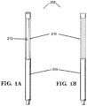
- guide device 200 comprises an expandable member 210 and a guide tube 240 operatively coupled to expandable member 210 and having a distal tip 241, which is moveable between a first position generally parallel with expandable member 210 in a collapsed position and a second position askew to the first position.
- Expandable member 210 comprises a radially expandable or outwardly extending structure that is moveable between a collapsed position and an expanded position. Expandable member 210 may be structurally or materially configured to expand such that guide tube 240 operatively coupled thereto radially extends in an askew direction. Expandable member 210 may also be structurally or materially configured such that at least some continuous blood flow is maintained, e.g., with only minor disruption to flow, while the expandable member 210 is in its expanded position and/or during the transition to the expanded position. Expandable member 210 may be structurally or materially configured to provide additional support to the vessel at a treatment site, for example, by expanding in such a way as to contact vessel walls.
- expandable member 210 may be structurally or materially configured to snare an elongate member.
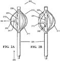
- FIGS. 2A and 2B illustrate an embodiment having an expandable member 210 in a expanded position
- FIGS. 1A and 1B illustrate an embodiment having an expandable member 210 in a collapsed position
- Expandable member 210 may be structurally or materially configured to be moveable between a collapsed position and an outwardly extending, expanded position. In addition, expandable member may be selectively actuated between the two positions. Expandable member 210 may be slideably actuated, inflatably actuated, self-expanding, spring actuated, combinations of the same, or actuated via any other mode of actuation.
- a guide device is deployable through a vessel to a treatment site.
- the guide device deploys an endovascular tool to the treatment site and channels the tool in a direction generally normal or off axis to the longitudinal axis of a stent device.
- the guide device may be detectable within the body with the use of ex vivo detectors, thereby facilitating the generally accurate positioning of the guide device.
- a guide device may comprise an expandable member configured to expand radially and a guide tube operatively coupled to the expandable member to channel in an endovascular tool in an askew, generally radial direction.
- Askew describes a direction that is generally at an angle from the path of delivery.
- the expandable member bends or extends outwardly and thus expands in response to a compression force that may be applied via the longitudinal displacement of an elongate member relative to another elongate member.
- an inflatable member may facilitate the expansion of the expandable member.
- the distal end of the guide tube or other portions may comprise radiopaque material to facilitate generally accurate positioning within the body.
- a method of use may comprise deploying through a vessel the guide device to a treatment site, and may further comprise outwardly extending or expanding an expandable member and channeling a subsequent tool (e.g., for puncture, cannulation, etc.) to the selected target.
- the guide device may be positioned with the use of a detector.
- An endovascular tool may be deployed through the guide device to the selected treatment site.
- endovascular targets that are configured to anchor into a branch vessel and facilitate fenestration of an aortic graft, stent, or stent graft while maintaining continuous aortic downstream perfusion throughout the stent deployment and fenestration.
- a disclosure of the system comprises a puncturing tool entering and piercing a stent graft from the renal artery side, a snare device entering from the abdominal aorta side.
- the snare device captures the puncture tool and pulls the tool with its accompanying guidewire through to the abdominal aorta access point.
- a stent device is deployed along this guide wire to stent the renal artery.
- expandable member 210 may be slideably actuated to an expanded position. Such expansion may be in response to corresponding longitudinal displacement of a second elongate member 230 relative to a first elongate member 220, which applies a compression force or tension force to expandable member 210.
- expandable member 210 at a first end may be connected to first elongate member 220, and the opposite second end is connected to second elongate member 230, such that expandable member 210 is deformed generally radially in response to selective axial displacement of second elongate member 230 relative to first elongate member 220. Collapsing expandable member 210 may be performed by selective axial displacement opposite that required to expand.
- first elongate member 220 may comprise a first lumen
- second elongate member 230 may comprise a second lumen and a side opening 231.
- Second elongate member 230 may be disposed along the first lumen
- side opening 231 may be adjacent to expandable member 210.
- guide tube 240 may be slideably housed along the second lumen of second elongate member 230, and guide tube 240 may pass through side opening 231 to connect with expandable member 210.
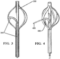
- FIG. 3 illustrates a cross-sectional view of guide tube 340 disposed along the lumen of second elongate member 330.
- a second elongate member does not comprise a side opening.
- the guide tube is slideably housed in the first elongate member lumen and disposed alongside the second elongate member.
- an "elongate member” has proximal and distal ends and is capable of passing through a vessel.
- an elongate member is flexible, especially when an elongate member is required to traverse through tortuous vasculature. Examples include a guidewire, catheter, optical fiber, or the like.
- An elongate member may comprise a lumen over the entire distance or a part thereof or may be solid throughout.
- An elongate member may comprise a blunt, rounded, or tapered distal tip, to name a few, and may be characterized by varying degrees of rigidity or softness, which may further vary along the length of the elongate member.
- Elongate members may have any cross-sectional shape including circular, oval, triangular, square, polygon shaped or randomly shaped.
- An elongate member, or any portion thereof, may be hydrophilic or hydrophobic.
- a "catheter” and/or “tube” is an elongate member comprising a lumen extending through from the proximal end to the distal end.
- Typical materials used to construct an elongate member can comprise materials such as Amorphous Commodity Thermoplastics that include Polymethyl Methacrylate (PMMA or Acrylic), Polystyrene (PS), Acrylonitrile Butadiene Styrene (ABS), Polyvinyl Chloride (PVC), Modified Polyethylene Terephthalate Glycol (PETG), Cellulose Acetate Butyrate (CAB); Semi-Crystalline Commodity Plastics that include Polyethylene (PE), High Density Polyethylene (HDPE), Low Density Polyethylene (LDPE or LLDPE), Polypropylene (PP), Polymethylpentene (PMP); Amorphous Engineering Thermoplastics that include Polycarbonate (PC), Polyphenylene Oxide (PPO), Modified Polyphenylene Oxide (Mod PPO), Polyphenylene Ether (PPE), Modified Polyphenylene Ether (Mod PPE), Thermoplastic Polyurethane (TPU); Semi-Crystalline Engineering Thermoplastic
- another expansion mechanism may comprise inflatable actuation, such as via an inflatable member.
- guide device 200 may comprise a balloon locatable within expandable member 210 that upon inflation outwardly extends expandable member 210.
- the inflatable member may be deflated and then confined by expandable member 210 when expandable member 210 transitions back to its collapsed position for withdrawal.
- expandable member 210 may be made to self-expand upon release from a constraining mechanism such as a sheath.
- expandable member 210 may be fabricated from shape-memory alloys or polymers such as stainless steel (SST), nitinol, polyurethanes, or the like such that it is configured as a passively expanding device.
- Guide device 200 may comprise any configuration or materials that facilitate expandable member 210 movement between its collapsed position and its outwardly extending expanded position.
- Expandable member 210 comprises bendable elements that are outwardly extendable.
- expandable member 210 may comprise a discontinuous or open structure when in the expanded position.
- a discontinuous or open structure permits fluid to flow across expandable member 210 with only minor fluid disruption. Maintaining downstream perfusion also relates to cannulation accuracy in the fact that guide device 200 need not withstand or resist pressures associated with temporary occlusion.
- expandable member 210 may comprise bendable elements that separate from each other, creating space therebetween, as these elements outwardly extend, such as a malecot structure, mesh member, or a flexible tube with diagonal or longitudinal slits.
- expandable member 210 may comprise at least one slat 211 connected at one end to first elongate member 220 and connected at the other end to second elongate member 230. Expandable member 210 may be integral with first elongate member 220, second elongate member 230, or a separate structure connected thereto.
- expandable member 210 may be radially symmetrical or only occur about a fraction of the perimeter of expandable member 210 creating radial asymmetry. Moreover, the distance that expandable member 210 expands or outwardly extends from the longitudinal axis may vary about the perimeter of expandable member 210 or be uniform. Such variations providing an asymmetrical profile to expandable member 210 may yield various benefits such as a wider turning radius or greater flexibility in the types of endovascular tools deployable through guide tube 240. For example, in an embodiment, expandable member 210 may comprise different materials with varying degrees of rigidity such that one side of expandable member 210 outwardly extends more so than the opposite side.
- Expandable member 210 comprises a flexible material that is sufficiently rigid and strong enough to outwardly extend distal tip 241 and maintain its expanded position during a procedure.
- expandable member 210 may comprise a material that is sufficiently rigid to support the vessel wall during a procedure, such as a fenestration procedure. Expandable member 210 may have a generally curved profile when in an expanded position to minimize vessel wall trauma about any points of contact.
- Expandable member 210 may be comprised of any number of biocompatible materials including nitinol, silicon, latex, polyurethane, polyvinyl chloride, polysiloxanes, polycarbonate, polyethylene, nylon, PTFEs (e.g., ePTFEs), stainless steel, or any biocompatible material, including combinations of the foregoing.
- biocompatible materials including nitinol, silicon, latex, polyurethane, polyvinyl chloride, polysiloxanes, polycarbonate, polyethylene, nylon, PTFEs (e.g., ePTFEs), stainless steel, or any biocompatible material, including combinations of the foregoing.
- the width or diameter of expandable member 210 in its expanded position may be adjustable across a range of widths or diameters.
- the expandable member 210 in its expanded position may comprise a range of widths or diameters within the following values: about 1mm to about 65mm, about 2mm to about 45mm, or about 3mm to about 30mm.
- guide device 200 of a certain configuration may be adaptable to a variety of vessel diameters.
- guide device 200 may be scaleable, and thus, utilized in a variety of applications, such as procedures in the peripheral vasculature.
- Expandable member 210 may comprise a radiopaque, echogenic, or magnetic material, or any other material capable of ex vivo detection. This material may be an integral part of member 210, a coating, or a separate marker connected thereto.
- expandable member 210 may be configured to be a vessel diameter-measuring device.
- guide device 200 may comprise a calibrated scale on the proximal end of second elongate member 230 so that the degree of expansion correlates to an axial position on second elongate member 230. Knowing the vessel diameter can assist with determining the appropriate diametrical size of the stent or stent graft to utilize. In addition, applying an internally distensive force while measuring the vessel diameter may further assist in selecting a stent or stent graft. The force applied by the device during measurement should correlate to the force applied by a stent or stent graft in the same place.
- Guide tube 240 is operatively coupled or connected to expandable member 210 such that when expandable member 210 moves to its expanded position, distal tip 241 radially or outwardly extends therewith.
- Guide tube 240 may be connected such that an endovascular tool may pass through the distal end of guide tube 240.
- expandable member 210 may comprise an aperture 213.
- Aperture 213 is any opening located on expandable member 210 that permits an endovascular tool to pass through guide tube 240 with obstruction from expandable member 210.
- Guide tube 240 may be connected to expandable member 210 such that the distal exit of guide tube 240 is coincident the aperture 213.
- guide tube 240 comprises any structure configured to guide an endovascular tool to a site radial, generally orthogonal, or otherwise askew or off-axis the path of delivery 250.
- guide tube 240 can comprise an elongate member having a proximal and distal end with a lumen therethrough
- guide tube can comprise a half tube, trough, or some other rail- or track-like configuration to guide the endovascular tool in an askew direction.
- guide tube 240 may direct an endovascular tool, such as that described in U.S. Patent App. Serial No. 13/273,111 to Cully et al. , in a substantially constant angle throughout the range of expanded position diameters or widths.
- Guide tube 240 may be modified to have a variety of structural properties as is suited for the endovascular tool to be delivered. For example, guiding a fluid via guide tube 240 may not require the same structural properties as would be required from a piercing catheter or the like. Similarly, guide tube 240 can have a collapsible or flimsy configuration that expands as the endovascular tool passes through its lumen, if present. This collapsible configuration can reduce the profile of guide device 200 as traverses through the vasculature to the treatment site.
- Guide tube 240 operatively couples or connects to expandable member 210 such that guide tube 240 outwardly extends when expandable member 210 is its expanded position.
- distal tip 241 is movable between a first position, in which the end of distal tip 241 is generally coaxial or generally parallel with expandable member 210 in its collapsed position, and a second position, in which distal tip 241 extends askew or in a generally orthogonal or radial direction, as expandable member 210 is expanded.
- Distal tip 241 of guide tube 240 may be operatively coupled to expandable member 210 coincident aperture 213.
- distal tip 241 of the guide tube 240 may be coupled tangentially to expandable member 210.
- the present disclosure includes any configuration that radially extends guide tube 240 when expandable member 210 is its expanded position such that an endovascular tool can pass through guide tube 240.
- the distal tip 241 of guide tube 240 or a portion thereof comprises a radiopaque, echogenic, or magnetic material, or any other material capable of ex vivo detection.
- This material may be an integral part of tip 241, a coating, or a separate marker connected thereto.
- guide device 200 may be configured to be a drug delivery device.
- a drug may reside within expandable member 210 such that the drug is generally confined while expandable member 210 is in a collapsed position. Once expandable member 210 reaches the treatment site, expandable member 210 may expand to release the drug into the vasculature.
- the drug may be injected into guide tube 240, or an endovascular tool may comprise a drug delivery tool that can be delivered through guide tube 240 toward a desired treatment site. Such tools may be configured to penetrate a mass and deliver a drug directly into the mass.
- a method for using guide device 200 may comprise the steps of deploying guide device 200 into a vessel and outwardly extending the expandable member 210 to an expanded position and thereby causing movement of distal tip 241 to its second position. Such expansion may be executed without substantially disrupting fluid flow through the vessel. Distal tip 241 in the second position may extend toward a treatment site on the vessel wall, thereby directing an endovascular tool passed through guide tube 240 toward the treatment site.
- expandable member 210 is outwardly extended by applying a compression force to expandable member 210, such as through longitudinal displacement of second elongate member 230 relative to first elongate member 220, thereby radially or outwardly extending distal tip 241.
- expandable member 210 is outwardly extended by inflating an inflatable member.
- a further disclosure comprises selectively positioning guide device 200 with the assistance of a detector, ex vivo, showing an in vivo position of the distal tip 241 or expandable member 210. Then, an endovascular tool, such as that described in U.S. Patent App. Serial No. 13/273,111 to Cully et al. , may be advanced through the distal end of guide tube 240. For example, FIG. 4 illustrates an endovascular tool 450 advanced through guide tube 440. A further embodiment involves puncturing a selected site with endovascular tool 450. A further disclosure involves injecting a contrast agent into guide tube 440 or an endovascular tool to verify a side branch has been fenestrated and/or cannulated or verify that the side branch is in fluid communication with the main vessel.
- an endovascular target 510A,B is a temporary or permanent implant that serves as a target for an endovascular tool. Endovascular target 510A,B facilitates the perfusion of fluid through a branch vessel 501.
- An embodiment of endovascular target 510A,B comprises an elongate member 513A,B, with a lumen at least in the distal region of elongate member 513A,B and at least one opening 512A,B in the wall of elongate member 513A,B accessing the lumen, and a distal anchor 511A,B.
- distal anchor 511A,B is configured to be positioned fixedly in branch vessel 501.
- Distal anchor 511A,B may be integral with elongate member 513A,B or a separate structure attached thereto.
- Distal anchor 511A,B may comprise a helix (e.g., as illustrated in FIG. 5B ), a ring, a perforated disc, an inflatable member (e.g., as illustrated in FIG. 5A ) or any structure configured to position fixedly in branch vessel 501.
- Distal anchor 511A,B may comprise detectable material such as a magnetic, radiopaque, echogenic, or fluorescent material, or any other material capable of ex vivo detection, such as with the use of electromagnetic radiation, fluoroscopy, an angioscope, or otherwise.
- the inflation medium may be radiopaque.
- the diameter of distal anchor 511A,B across the widest portion thereof when it is fixedly positioned is from about 1mm to about 15mm, from about 4mm to about 7mm, or from about 3mm to about 6mm.
- Distal anchor 511A,B may be comprised of any number of materials including silicon, latex, polycarbonate, polysiloxane, polyurethane, polyvinyl chloride, polyethylene, nylon, PTFEs (e.g., ePTFEs), nitinol, or any biocompatible material, including combinations of the foregoing.
- distal anchor 511A,B comprises a coating of heparin or other anti-coagulant agent.
- opening 512A,B there may be any number, position, or configuration of opening 512A,B in the wall of elongate member 513A,B. Opening 512A,B facilitates perfusion of the side branch vasculature.
- the position of opening 512A,B along elongate member 513A,B is such that opening 512A,B is located in main vessel 500 beyond the reach of a stent deployed in main vessel 500 when distal anchor 511A,B is fixedly positioned in branch vessel 501. This will allow a fluid such as blood to enter the lumen and facilitate perfusion of the side branch vasculature and downstream organs (e.g., kidneys).
- Opening 512A,B may be configured such that blood readily passes through opening 512A,B and into the lumen of elongate member 513A,B, in a retrograde direction from that of the main vessel if required.
- a flap may be utilized to facilitate one-way flow through opening 512 A,B.
- the wall of elongate member 513A,B is not compromised. Stated another way, there is no opening for perfusion.
- the lumen extends to the hub of elongate member 513A,B where the clinician may utilize it for perfusion of the side branch and its associated vasculature by injecting fluid, such as autologous blood or otherwise, with a syringe.
- a clinician may see fit to modify by creating opening 512A,B for retrograde perfusion by skiving the side of elongate member 513A,B, for example, with a scalpel blade.
- Another disclosure comprises the steps of deploying endovascular target 510A,B as described herein into branch vessel 501 via main vessel 500 and fixedly positioning distal anchor 511A,B in branch vessel 501.
- a guide system may comprise an endovascular target and a guide device as described herein to facilitate the lateral and rotational positioning of the guide device.
- a further embodiment comprises a detector, an angioscope, or the like to facilitate the lateral and rotational positioning of guide device.
- Another disclosure comprises the steps of deploying an endovascular target to a treatment area and positioning the endovascular target into branch vessel 501. Further steps involve deploying a primary stent device in main vessel 500, deploying a guide device as described herein to the grafted area, expanding the expandable member, and positioning the guide device relative to the endovascular target 510A,B with the use of a detector, an angioscope, or the like.
- a further disclosure comprises deploying an endovascular tool through the guide tube to pierce the stent device proximate distal anchor 511A,B.
- Other disclosures may comprise deploying a balloon device to the puncture site to expand the perforation and deploying a branch stent device to stent branch vessel 501.
- Embodiments of the branch stent device may comprise a stent device, as that term is defined herein, gaskets, seals, flanges, self-expanding configurations, balloon-expanding configurations, or any combination of the foregoing.
- Another embodiment comprises a guide device as described herein, configured to permit an angioscope to pass through the guide tube, a stent device comprising a transparent to translucent stent wall, and an angioscope.
- the angioscope advances through the guide tube of the guide device.
- the guide device facilitates the lateral and rotational positioning.
- the angioscope permits the visual verification a branch vessel ostium through the transparent to translucent stent graft wall so that a fenestration tool or piercing guide tube may be deployed through the guide tube to fenestrate the stent graft at the branch vessel junction.
- a further disclosure may comprise deploying a balloon device to the pierced stent to expand the perforation and deploying a branch stenting device to stent the branch vessel.
- a reverse cannulation system comprises a snare device 610 comprising an expandable member 615 as described herein, puncture guide device 620, and a primary stent device 630.
- the primary stent device 630 comprises a stent or a stent graft, both of which may be balloon expanding or self-expanding.
- An embodiment of a stent device comprises graft materials or fibers configured to prevent ripping or tearing upon puncturing or ballooning.
- expandable member 615 may expand the primary stent device 630.
- a puncture guide catheter 622 supports and guides a puncture tool 621 to the piercing site on the stent graft.
- Puncture guide device 620 comprises a puncture guide catheter 622 having at least one lumen 623 with a perfusable anchor 624 at distal exterior of catheter 622 and a puncture tool 621 supportable by the puncture guide catheter 622.
- the puncture guide catheter 622 provides the required column strength via lumen 623 to the puncture tool 621 for piercing the primary stent device 630.
- Puncture guide catheter may comprise a second lumen to allow for perfusion of blood to the kidney. Blood may be injected into second lumen as needed. The second lumen may be coated with heparin.
- puncture tool 621 comprises an elongate member and a tapered or sharp tip at a distal end.
- puncture tool 621 may comprise a piercing catheter.
- puncture tool 621 is energized with electromagnetic radiation, such as radio-frequency energy and the like, or mechanical energy.
- An embodiment of perfusable anchor 624 can comprise at least one inflatable member connected to the distal exterior of catheter 622.
- the inflatable member is of sufficient size to stabilize catheter 622 in the branch vessel.
- Other embodiments of perfusable anchor 624 comprise at least one ring connected to the distal exterior of catheter 622, such that fluid passes through the ring and the ring assists in anchoring punch guide catheter 622.
- Perfusable anchor 624 may comprise any number or variety of ringed geometric shapes connected to the distal exterior of catheter 622.
- Perfusable anchor 624 may comprise an expandable, perfusable mechanical anchor, such as an expandable braid, in lieu of an inflatable member.
- Other embodiments of perfusable anchor 624 may comprise a perforated disc or the endovascular target as described herein.
- snare device 610 comprises an expandable member 615 as described herein.
- first elongate member 612 and second elongate member 614 connect to an end opposite the other of expandable member 615 such that the longitudinal displacement of second elongate member 614 relative to first elongate member 612 expands and collapses expandable member 615.
- Other embodiments of snare device 610 comprise the guide device as described herein.
- Use of expandable member 615 also allows for propping or bolstering the stent graft inner diameter in preparation for an in-situ fenestration. This added support may be helpful when puncturing strong stent graft material.
- Embodiments of snare device 610 may be configured to capture, hook, entangle, or the like a guidewire or puncture tool.
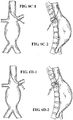
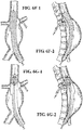
- another disclosure comprises the steps of accessing a side-branch through a lumbar access with a needle and/or lumbar stick ( FIG. 6A-6B ); advancing a guide wire through the needle and gaining access through the branch vessel (e.g., renal artery) to the main vessel (e.g., aorta) ( FIG. 6C ); removing the needle and/or lumbar stick; advancing a puncture guide device over the guide wire ( FIG. 6D ); positioning the puncture guide device as described herein in the branch vessel near a junction with a main vessel ( FIG. 6D ); withdrawing the guide wire from the main vessel ( FIG.
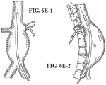
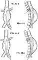
- FIG. 6E advancing a primary stent device through the main vessel proximate the junction ( FIG. 6E ); deploying the primary stent device ( FIG. 6F ); advancing a snare device as described herein so that the expandable member is proximate the junction ( FIG. 6G ); expanding the expandable member ( FIG. 6G ); advancing a puncture tool through the puncture guide catheter to pierce the primary stent device and into the expandable member ( FIG. 6H ); collapsing the expandable member and withdrawing the expandable member with the puncture tool in tow ( FIG. 6I ). Because of these steps, an elongate member is threaded from a secondary access point into a branch vessel to the main vessel and out through a primary access point.
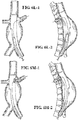
- a further disclosure comprises the step of advancing a balloon catheter into the puncture site ( FIG. 6J ); ballooning the punctured site to further open the puncture ( FIG. 6J ); withdrawing the elongate member from the secondary access point into the branch vessel ( FIG. 6K ); withdrawing the balloon catheter; advancing the secondary stent device through the punctured site ( FIG. 6L ); and deploying the branch stent device ( FIG. 6M ).
- Embodiments of the branch stent device may comprise gaskets, seals, flanges, self-expanding configurations, balloon-expanding configurations, or any combination of the foregoing.
Description
- The present disclosure relates to the field of endoluminal products, and more particularly, to the field of fenestration devices.
- Endovascular surgery is a minimally invasive method of treating vascular diseases from inside the blood vessel. Benefits of minimally invasive procedures include shorter hospital stays, quicker recoveries, and lower risk of complications. Difficulties with endovascular procedures include traversing irregularly shaped, highly tortuous, heavily branched, and very narrow vessels to gain access to the treatment site, and once access is gained, difficulties further include fine-tuning the rotational and lateral position of the tool. Another difficulty relates to maintaining continued blood flow through the vessels during the course of treatment.
- When a stent graft is deployed, branch vessels in the proximity of the stent graft can become sealed off from the flow of blood. In order to maintain blood flow, the graft must be fenestrated at the branch vessel junction. This can be problematic because stent graft materials are typically very strong and durable in order to survive conditions within a mobile host vessel for many years, and puncturing this durable material endovascularly adds to the difficulty of the task. Procedures within the aorta present even more challenges, as compared to other vascular treatment sites, because the size and shape of the aorta and the dynamics of blood flow.
- Safe preservation of blood flow to the supra-aortic branches during the procedure and subsequently is desirable. In situ fenestration of aortic devices has the potential to allow for continued perfusion of supra-aortic branches, without the need for extra-anatomic bypass, and without the need for custom-made devices. The angle formed by the branch vessel relative to the main vessel is an obstacle to success with this technique.
-
WO 99/42047 - Therefore, a need exists to develop better devices, systems, and methods for endovascular treatment of vessels that permit more accurate positioning and continued blood flow, especially with respect to in situ fenestration of aortic devices. In addition, a need exists for incorporating multiple tools within a single device capable of accurate positioning and continued blood flow that canalize the selected sites.
- The present invention provides devices according to appended claims 1-12. The device may be for guiding an endovascular tool, such as a puncturing tool or an angioscope, in an askew direction, such as toward or through the sidewall of a vessel or a stent device, as that term is defined herein, using cooperative elongate members. The present disclosure is generally directed toward devices for locating branch vessels from within a grafted main vessel and directing endovascular tools to the branch-main vessel junction. Illustrative embodiments may be useful to pierce grafts or stent-grafts to create fenestrations. Illustrative embodiments may be useful to treat aneurysms, dissections, and other pathologies located in the aortic arch. Illustrative embodiments may be useful in connection with the treatment of coronary artery disease, peripheral vascular diseases, portal hypertension, carotid artery disease, renal vascular hypertension, amongst other conditions affecting anatomical conduits. Illustrative embodiments may also be useful to deliver drugs or other implantable devices to specific treatment sites. The methods disclosed herein do not form part of the claimed invention, but illustrate the intended use of the claimed device.
- The accompanying drawings provide a further understanding of the present disclosure and are incorporated in and constitute a part of this specification, illustrate embodiments of the disclosure, and together with the description serve to explain the principles of the disclosure.
-
FIG. 1A illustrates a perspective view of an embodiment in a collapsed position; -
FIG. 1B illustrates a side view of an embodiment in a collapsed position; -
FIG. 2A illustrates a side view of an embodiment in an expanded position; -
FIG. 2B illustrates a perspective view of an embodiment in an expanded position; -
FIG. 3 illustrates a cross-section at a side view of an embodiment in an expanded position; -
FIG. 4 illustrates a perspective view of an embodiment in an expanded position with a fenestration tool deployed through the distal end of a third elongate member; -
FIG. 5A illustrates a cross-section view of an embodiment of an endovascular target with a inflatable distal anchor positioned in a branch vessel and a side view of the endovascular target; -
FIG. 5B illustrates a cross-section view of an embodiment of an endovascular target with a helical distal anchor positioned in a branch vessel and a side view of the endovascular target; and -
FIGS. 6A-6M illustrate steps to stent a main vessel and a branch vessel. - Persons skilled in the art will readily appreciate that various aspects of the present disclosure may be realized by any number of apparatuses configured to perform the intended functions. Stated differently, apparatuses may be incorporated herein to perform the intended functions. It should also be noted that the accompanying drawing figures referred to herein are not all drawn to scale, but may be exaggerated to illustrate various aspects of the present disclosure, and in that regard, the drawing figures should not be construed as limiting. Finally, although the present disclosure may be described in connection with various principles and beliefs, the present disclosure should not be bound by theory.
- The terms "proximal" and "distal," when used herein in relation to a device or device component refer to directions closer to and farther away from the operator of the device. Since the present disclosure is not limited to peripheral or central approaches, the device should not be narrowly construed when using the terms proximal or distal since device features may be slightly altered relative to the anatomical features and the device position relative thereto.
- The present disclosure is directed toward devices for guiding an endovascular tool, such as a puncturing tool or an angioscope, in an askew direction, such as toward or through the sidewall of a vessel or a stent device, as that term is defined herein using elongate members and specialized catheters. The present disclosure is directed toward devices for locating branch vessels from within a grafted main vessel and directing endovascular tools to the branch-main vessel junction. Illustrative embodiments may be useful to pierce grafts or stent-grafts to create fenestrations. Illustrative embodiments may be useful to treat aneurysms, dissections, and other pathologies located in the aortic arch. Illustrative embodiments may be useful in connection with the treatment of coronary artery disease, peripheral vascular diseases, portal hypertension, carotid artery disease, renal vascular hypertension, amongst other conditions affecting anatomical conduits. Illustrative embodiments may also be useful to deliver drugs and other implantable devices to specific treatment sites.
- As used herein, a "vessel" may be an artery, vein, capillary or the like, or any other anatomical passageway such as stomach or intestine, conduit or lumen existing in a healthy subject. As used herein, "connected" means to join, couple, attach two or more elements whether directly or indirectly, whether permanently or temporarily. As used herein, a "stent device" may refer to a graft, a stent, stent graft, or any other device that may require a fenestration.
- In accordance with this disclosure, a guide device is deployable through a vessel to a treatment site. The guide device deploys an endovascular tool to the treatment site and directs or channels the tool in a direction generally normal or off axis to the longitudinal axis of a stent device. In a further disclosure, the guide device may be detectable within the body with the use of ex vivo detectors, thereby facilitating the generally accurate positioning of the guide device.
- A guide device may comprise an expandable member configured to expand radially and a guide tube operatively coupled to the expandable member to channel or guide an endovascular tool in an askew, generally radial direction. Askew, as used herein, describes a direction that is generally at an angle from the path of delivery. In an embodiment, the expandable member bends or extends outwardly and thus expands in response to a compression force that may be applied via the longitudinal displacement of an elongate member relative to another elongate member. In other embodiments, an inflatable member may facilitate the expansion of the expandable member. The distal end of the guide tube or other portions may comprise radiopaque material to facilitate generally accurate positioning within the body.
- A method of use disclosed herein may comprise deploying through a vessel the guide device to a treatment site, and may further comprise outwardly extending or expanding an expandable member and channeling a subsequent tool (e.g., for puncture, cannulation, etc.) to the selected target. The guide device may be positioned with the use of a detector. An endovascular tool may be deployed through the guide device to the selected treatment site.
- Other aspects of the present disclosure involve endovascular targets that are configured to anchor into a branch vessel and facilitate fenestration of an aortic graft, stent, or stent graft while maintaining continuous aortic downstream perfusion throughout the stent deployment and fenestration.
- Another aspect involves a reverse cannulation system, particularly useful for stenting the abdominal aorta proximate the renal arteries and stenting the renal artery. A disclosure of the system comprises a puncturing tool entering and piercing a stent graft from the renal artery side, a snare device entering from the abdominal aorta side. The snare device captures the puncture tool and pulls the tool with its accompanying guidewire through to the abdominal aorta access point. A stent device is deployed along this guide wire to stent the renal artery.
- Persons skilled in the art will appreciate that the embodiments described herein may be useful in, amongst other things, endovascular treatments to remotely turn or angle endovascular tools with some degree of precision, to make in-situ fenestrations at an angle, to pierce sidewalls of strong, durable graft material in-situ, to maintain the perfusion of branch vessels, and to cross or create one or more ducts through a wide variety of anatomical features.
- In accordance with an embodiment, and with reference to
FIGS. 1A, 1B ,2A and 2B , aguide device 200 may be structurally or materially configured to deploy an endovascular tool or implant to the treatment site and channel the tool in adirection 251 generally radial, generally orthogonal, or otherwise off axis from its path ofdelivery 250. An "endovascular tool" comprises any tool capable of use in endovascular procedures, such as a puncturing tool as described herein, piercing catheter, re-entry device, dual-lumen re-entry device, an angioscope, an elongate member, a guide device as described herein, an endovascular target as described herein, a stent, a stent graft, a drug delivery tool, amongst other endovascular tools, and combinations thereof. Exemplary "piercing catheters," "re-entry devices," "dual-lumen re-entry devices," and combinations thereof are more fully described inU.S. Patent Application Serial No. 13/273,111 to Cully et al. , entitled "System and Method of Percutaneous Occlusion Crossing". - In accordance with an embodiment,
guide device 200 comprises anexpandable member 210 and aguide tube 240 operatively coupled toexpandable member 210 and having adistal tip 241, which is moveable between a first position generally parallel withexpandable member 210 in a collapsed position and a second position askew to the first position. -
Expandable member 210 comprises a radially expandable or outwardly extending structure that is moveable between a collapsed position and an expanded position.Expandable member 210 may be structurally or materially configured to expand such thatguide tube 240 operatively coupled thereto radially extends in an askew direction.Expandable member 210 may also be structurally or materially configured such that at least some continuous blood flow is maintained, e.g., with only minor disruption to flow, while theexpandable member 210 is in its expanded position and/or during the transition to the expanded position.Expandable member 210 may be structurally or materially configured to provide additional support to the vessel at a treatment site, for example, by expanding in such a way as to contact vessel walls. In addition,expandable member 210 may be structurally or materially configured to snare an elongate member. In this regard,FIGS. 2A and 2B illustrate an embodiment having anexpandable member 210 in a expanded position andFIGS. 1A and 1B illustrate an embodiment having anexpandable member 210 in a collapsed position -
Expandable member 210 may be structurally or materially configured to be moveable between a collapsed position and an outwardly extending, expanded position. In addition, expandable member may be selectively actuated between the two positions.Expandable member 210 may be slideably actuated, inflatably actuated, self-expanding, spring actuated, combinations of the same, or actuated via any other mode of actuation. - In accordance with this disclosure, a guide device is deployable through a vessel to a treatment site. The guide device deploys an endovascular tool to the treatment site and channels the tool in a direction generally normal or off axis to the longitudinal axis of a stent device. In a further disclosure, the guide device may be detectable within the body with the use of ex vivo detectors, thereby facilitating the generally accurate positioning of the guide device.
- A guide device may comprise an expandable member configured to expand radially and a guide tube operatively coupled to the expandable member to channel in an endovascular tool in an askew, generally radial direction. Askew, as used herein, describes a direction that is generally at an angle from the path of delivery. In an embodiment, the expandable member bends or extends outwardly and thus expands in response to a compression force that may be applied via the longitudinal displacement of an elongate member relative to another elongate member. In other embodiments, an inflatable member may facilitate the expansion of the expandable member. The distal end of the guide tube or other portions may comprise radiopaque material to facilitate generally accurate positioning within the body.
- A method of use is disclosed which may comprise deploying through a vessel the guide device to a treatment site, and may further comprise outwardly extending or expanding an expandable member and channeling a subsequent tool (e.g., for puncture, cannulation, etc.) to the selected target. The guide device may be positioned with the use of a detector. An endovascular tool may be deployed through the guide device to the selected treatment site.
- Other aspects of the present disclosure involve endovascular targets that are configured to anchor into a branch vessel and facilitate fenestration of an aortic graft, stent, or stent graft while maintaining continuous aortic downstream perfusion throughout the stent deployment and fenestration.
- Another aspect involves a reverse cannulation system, particularly useful for stenting the abdominal aorta proximate the renal arteries and stenting the renal artery. A disclosure of the system comprises a puncturing tool entering and piercing a stent graft from the renal artery side, a snare device entering from the abdominal aorta side. The snare device captures the puncture tool and pulls the tool with its accompanying guidewire through to the abdominal aorta access point. A stent device is deployed along this guide wire to stent the renal artery.
- For example,
expandable member 210 may be slideably actuated to an expanded position. Such expansion may be in response to corresponding longitudinal displacement of a secondelongate member 230 relative to a firstelongate member 220, which applies a compression force or tension force toexpandable member 210. As such,expandable member 210 at a first end may be connected to firstelongate member 220, and the opposite second end is connected to secondelongate member 230, such thatexpandable member 210 is deformed generally radially in response to selective axial displacement of secondelongate member 230 relative to firstelongate member 220. Collapsingexpandable member 210 may be performed by selective axial displacement opposite that required to expand. - In such an embodiment, first
elongate member 220 may comprise a first lumen, and secondelongate member 230 may comprise a second lumen and aside opening 231. Secondelongate member 230 may be disposed along the first lumen, andside opening 231 may be adjacent toexpandable member 210. In one embodiment, guidetube 240 may be slideably housed along the second lumen of secondelongate member 230, and guidetube 240 may pass throughside opening 231 to connect withexpandable member 210. For example,FIG. 3 illustrates a cross-sectional view ofguide tube 340 disposed along the lumen of secondelongate member 330. In an alternative embodiment, a second elongate member does not comprise a side opening. In such an embodiment, the guide tube is slideably housed in the first elongate member lumen and disposed alongside the second elongate member. - As used herein, an "elongate member" has proximal and distal ends and is capable of passing through a vessel. Typically, an elongate member is flexible, especially when an elongate member is required to traverse through tortuous vasculature. Examples include a guidewire, catheter, optical fiber, or the like. An elongate member may comprise a lumen over the entire distance or a part thereof or may be solid throughout. An elongate member may comprise a blunt, rounded, or tapered distal tip, to name a few, and may be characterized by varying degrees of rigidity or softness, which may further vary along the length of the elongate member. Elongate members may have any cross-sectional shape including circular, oval, triangular, square, polygon shaped or randomly shaped. An elongate member, or any portion thereof, may be hydrophilic or hydrophobic. As used herein, a "catheter" and/or "tube" is an elongate member comprising a lumen extending through from the proximal end to the distal end.
- Typical materials used to construct an elongate member can comprise materials such as Amorphous Commodity Thermoplastics that include Polymethyl Methacrylate (PMMA or Acrylic), Polystyrene (PS), Acrylonitrile Butadiene Styrene (ABS), Polyvinyl Chloride (PVC), Modified Polyethylene Terephthalate Glycol (PETG), Cellulose Acetate Butyrate (CAB); Semi-Crystalline Commodity Plastics that include Polyethylene (PE), High Density Polyethylene (HDPE), Low Density Polyethylene (LDPE or LLDPE), Polypropylene (PP), Polymethylpentene (PMP); Amorphous Engineering Thermoplastics that include Polycarbonate (PC), Polyphenylene Oxide (PPO), Modified Polyphenylene Oxide (Mod PPO), Polyphenylene Ether (PPE), Modified Polyphenylene Ether (Mod PPE), Thermoplastic Polyurethane (TPU); Semi-Crystalline Engineering Thermoplastics that include Polyamide (PA or Nylon), Polyoxymethylene (POM or Acetal), Polyethylene Terephthalate (PET, Thermoplastic Polyester), Polybutylene Terephthalate (PBT, Thermoplastic Polyester), Ultra High Molecular Weight Polyethylene (UHMW-PE); High Performance Thermoplastics that include Polyimide (PI, Imidized Plastic), Polyamide Imide (PAI, Imidized Plastic), Polybenzimidazole (PBI, Imidized Plastic); Amorphous High Performance Thermoplastics that include Polysulfone (PSU), Polyetherimide (PEI), Polyether Sulfone (PES), Polyaryl Sulfone (PAS); Semi-Crystalline High Performance Thermoplastics that include Polyphenylene Sulfide (PPS), Polyetheretherketone (PEEK); and Semi-Crystalline High Performance Thermoplastics, Fluoropolymers that include Fluorinated Ethylene Propylene (FEP), Ethylene Chlorotrifluroethylene (ECTFE), Ethylene, Ethylene Tetrafluoroethylene (ETFE), Polychlortrifluoroethylene (PCTFE), Polytetrafluoroethylenes (PTFEs), expanded Polytetrafluoroethylenes (ePTFEs), Polyvinylidene Fluoride (PVDF), Perfluoroalkoxy (PFA). Other commonly known medical grade materials include elastomeric organosilicon polymers, polyether block amide or thermoplastic copolyether (PEBAX) and metals such as stainless steel and nickel/titanium alloys.
- With reference back to
FIGS. 1A, 1B ,2A, and 2B , another expansion mechanism may comprise inflatable actuation, such as via an inflatable member. For example,guide device 200 may comprise a balloon locatable withinexpandable member 210 that upon inflation outwardly extendsexpandable member 210. The inflatable member may be deflated and then confined byexpandable member 210 whenexpandable member 210 transitions back to its collapsed position for withdrawal. - Alternatively,
expandable member 210 may be made to self-expand upon release from a constraining mechanism such as a sheath. In such embodiments,expandable member 210 may be fabricated from shape-memory alloys or polymers such as stainless steel (SST), nitinol, polyurethanes, or the like such that it is configured as a passively expanding device.Guide device 200 may comprise any configuration or materials that facilitateexpandable member 210 movement between its collapsed position and its outwardly extending expanded position. -
Expandable member 210 comprises bendable elements that are outwardly extendable. In addition,expandable member 210 may comprise a discontinuous or open structure when in the expanded position. A discontinuous or open structure permits fluid to flow acrossexpandable member 210 with only minor fluid disruption. Maintaining downstream perfusion also relates to cannulation accuracy in the fact thatguide device 200 need not withstand or resist pressures associated with temporary occlusion. For example,expandable member 210 may comprise bendable elements that separate from each other, creating space therebetween, as these elements outwardly extend, such as a malecot structure, mesh member, or a flexible tube with diagonal or longitudinal slits. Similarly,expandable member 210 may comprise at least oneslat 211 connected at one end to firstelongate member 220 and connected at the other end to secondelongate member 230.Expandable member 210 may be integral with firstelongate member 220, secondelongate member 230, or a separate structure connected thereto. - The expansion of
expandable member 210 may be radially symmetrical or only occur about a fraction of the perimeter ofexpandable member 210 creating radial asymmetry. Moreover, the distance thatexpandable member 210 expands or outwardly extends from the longitudinal axis may vary about the perimeter ofexpandable member 210 or be uniform. Such variations providing an asymmetrical profile toexpandable member 210 may yield various benefits such as a wider turning radius or greater flexibility in the types of endovascular tools deployable throughguide tube 240. For example, in an embodiment,expandable member 210 may comprise different materials with varying degrees of rigidity such that one side ofexpandable member 210 outwardly extends more so than the opposite side. -
Expandable member 210 comprises a flexible material that is sufficiently rigid and strong enough to outwardly extenddistal tip 241 and maintain its expanded position during a procedure. In addition,expandable member 210 may comprise a material that is sufficiently rigid to support the vessel wall during a procedure, such as a fenestration procedure.Expandable member 210 may have a generally curved profile when in an expanded position to minimize vessel wall trauma about any points of contact.Expandable member 210 may be comprised of any number of biocompatible materials including nitinol, silicon, latex, polyurethane, polyvinyl chloride, polysiloxanes, polycarbonate, polyethylene, nylon, PTFEs (e.g., ePTFEs), stainless steel, or any biocompatible material, including combinations of the foregoing. - The width or diameter of
expandable member 210 in its expanded position may be adjustable across a range of widths or diameters. For example, theexpandable member 210 in its expanded position may comprise a range of widths or diameters within the following values: about 1mm to about 65mm, about 2mm to about 45mm, or about 3mm to about 30mm. As such,guide device 200 of a certain configuration may be adaptable to a variety of vessel diameters. Similarly,guide device 200 may be scaleable, and thus, utilized in a variety of applications, such as procedures in the peripheral vasculature. -
Expandable member 210 may comprise a radiopaque, echogenic, or magnetic material, or any other material capable of ex vivo detection. This material may be an integral part ofmember 210, a coating, or a separate marker connected thereto. - In various embodiments,
expandable member 210 may be configured to be a vessel diameter-measuring device. For example,guide device 200 may comprise a calibrated scale on the proximal end of secondelongate member 230 so that the degree of expansion correlates to an axial position on secondelongate member 230. Knowing the vessel diameter can assist with determining the appropriate diametrical size of the stent or stent graft to utilize. In addition, applying an internally distensive force while measuring the vessel diameter may further assist in selecting a stent or stent graft. The force applied by the device during measurement should correlate to the force applied by a stent or stent graft in the same place. -
Guide tube 240 is operatively coupled or connected toexpandable member 210 such that whenexpandable member 210 moves to its expanded position,distal tip 241 radially or outwardly extends therewith.Guide tube 240 may be connected such that an endovascular tool may pass through the distal end ofguide tube 240. As such,expandable member 210 may comprise anaperture 213.Aperture 213 is any opening located onexpandable member 210 that permits an endovascular tool to pass throughguide tube 240 with obstruction fromexpandable member 210.Guide tube 240 may be connected toexpandable member 210 such that the distal exit ofguide tube 240 is coincident theaperture 213. - In an embodiment, guide
tube 240 comprises any structure configured to guide an endovascular tool to a site radial, generally orthogonal, or otherwise askew or off-axis the path ofdelivery 250. For example, guidetube 240 can comprise an elongate member having a proximal and distal end with a lumen therethrough Alternatively, guide tube can comprise a half tube, trough, or some other rail- or track-like configuration to guide the endovascular tool in an askew direction. In addition,guide tube 240 may direct an endovascular tool, such as that described inU.S. Patent App. Serial No. 13/273,111 to Cully et al. , in a substantially constant angle throughout the range of expanded position diameters or widths. -
Guide tube 240 may be modified to have a variety of structural properties as is suited for the endovascular tool to be delivered. For example, guiding a fluid viaguide tube 240 may not require the same structural properties as would be required from a piercing catheter or the like. Similarly, guidetube 240 can have a collapsible or flimsy configuration that expands as the endovascular tool passes through its lumen, if present. This collapsible configuration can reduce the profile ofguide device 200 as traverses through the vasculature to the treatment site. -
Guide tube 240 operatively couples or connects toexpandable member 210 such thatguide tube 240 outwardly extends whenexpandable member 210 is its expanded position. In one embodiment,distal tip 241 is movable between a first position, in which the end ofdistal tip 241 is generally coaxial or generally parallel withexpandable member 210 in its collapsed position, and a second position, in whichdistal tip 241 extends askew or in a generally orthogonal or radial direction, asexpandable member 210 is expanded.Distal tip 241 ofguide tube 240 may be operatively coupled toexpandable member 210coincident aperture 213. In a different embodiment,distal tip 241 of theguide tube 240 may be coupled tangentially toexpandable member 210. However, the present disclosure includes any configuration that radially extendsguide tube 240 whenexpandable member 210 is its expanded position such that an endovascular tool can pass throughguide tube 240. - In an exemplary embodiment, the
distal tip 241 ofguide tube 240 or a portion thereof comprises a radiopaque, echogenic, or magnetic material, or any other material capable of ex vivo detection. This material may be an integral part oftip 241, a coating, or a separate marker connected thereto. - In various embodiments,
guide device 200 may be configured to be a drug delivery device. For example, a drug may reside withinexpandable member 210 such that the drug is generally confined whileexpandable member 210 is in a collapsed position. Onceexpandable member 210 reaches the treatment site,expandable member 210 may expand to release the drug into the vasculature. In other embodiments, the drug may be injected intoguide tube 240, or an endovascular tool may comprise a drug delivery tool that can be delivered throughguide tube 240 toward a desired treatment site. Such tools may be configured to penetrate a mass and deliver a drug directly into the mass. - In a disclosure, a method for using
guide device 200 such as described herein may comprise the steps of deployingguide device 200 into a vessel and outwardly extending theexpandable member 210 to an expanded position and thereby causing movement ofdistal tip 241 to its second position. Such expansion may be executed without substantially disrupting fluid flow through the vessel.Distal tip 241 in the second position may extend toward a treatment site on the vessel wall, thereby directing an endovascular tool passed throughguide tube 240 toward the treatment site. - In an embodiment,
expandable member 210 is outwardly extended by applying a compression force toexpandable member 210, such as through longitudinal displacement of secondelongate member 230 relative to firstelongate member 220, thereby radially or outwardly extendingdistal tip 241. Alternatively,expandable member 210 is outwardly extended by inflating an inflatable member. - A further disclosure comprises selectively positioning
guide device 200 with the assistance of a detector, ex vivo, showing an in vivo position of thedistal tip 241 orexpandable member 210. Then, an endovascular tool, such as that described inU.S. Patent App. Serial No. 13/273,111 to Cully et al. , may be advanced through the distal end ofguide tube 240. For example,FIG. 4 illustrates anendovascular tool 450 advanced throughguide tube 440. A further embodiment involves puncturing a selected site withendovascular tool 450. A further disclosure involves injecting a contrast agent intoguide tube 440 or an endovascular tool to verify a side branch has been fenestrated and/or cannulated or verify that the side branch is in fluid communication with the main vessel. - With reference to
FIG. 5A and 5B , various embodiments of the present disclosure comprise anendovascular target 510A,B. Endovascular target 510A,B is a temporary or permanent implant that serves as a target for an endovascular tool.Endovascular target 510A,B facilitates the perfusion of fluid through abranch vessel 501. An embodiment ofendovascular target 510A,B comprises anelongate member 513A,B, with a lumen at least in the distal region ofelongate member 513A,B and at least oneopening 512A,B in the wall ofelongate member 513A,B accessing the lumen, and adistal anchor 511A,B. - In an exemplary embodiment,
distal anchor 511A,B is configured to be positioned fixedly inbranch vessel 501.Distal anchor 511A,B may be integral withelongate member 513A,B or a separate structure attached thereto.Distal anchor 511A,B may comprise a helix (e.g., as illustrated inFIG. 5B ), a ring, a perforated disc, an inflatable member (e.g., as illustrated inFIG. 5A ) or any structure configured to position fixedly inbranch vessel 501.Distal anchor 511A,B may comprise detectable material such as a magnetic, radiopaque, echogenic, or fluorescent material, or any other material capable of ex vivo detection, such as with the use of electromagnetic radiation, fluoroscopy, an angioscope, or otherwise. In the case of the inflatable member, the inflation medium may be radiopaque. In exemplary embodiments, the diameter ofdistal anchor 511A,B across the widest portion thereof when it is fixedly positioned is from about 1mm to about 15mm, from about 4mm to about 7mm, or from about 3mm to about 6mm.Distal anchor 511A,B may be comprised of any number of materials including silicon, latex, polycarbonate, polysiloxane, polyurethane, polyvinyl chloride, polyethylene, nylon, PTFEs (e.g., ePTFEs), nitinol, or any biocompatible material, including combinations of the foregoing. In another embodiment,distal anchor 511A,B comprises a coating of heparin or other anti-coagulant agent. - In embodiments, there may be any number, position, or configuration of
opening 512A,B in the wall ofelongate member 513A,B. Opening 512A,B facilitates perfusion of the side branch vasculature. In an exemplary embodiment, the position of opening 512A,B alongelongate member 513A,B is such thatopening 512A,B is located inmain vessel 500 beyond the reach of a stent deployed inmain vessel 500 whendistal anchor 511A,B is fixedly positioned inbranch vessel 501. This will allow a fluid such as blood to enter the lumen and facilitate perfusion of the side branch vasculature and downstream organs (e.g., kidneys). Opening 512A,B may be configured such that blood readily passes throughopening 512A,B and into the lumen ofelongate member 513A,B, in a retrograde direction from that of the main vessel if required. A flap may be utilized to facilitate one-way flow throughopening 512 A,B. - In other embodiments, the wall of
elongate member 513A,B is not compromised. Stated another way, there is no opening for perfusion. The lumen extends to the hub ofelongate member 513A,B where the clinician may utilize it for perfusion of the side branch and its associated vasculature by injecting fluid, such as autologous blood or otherwise, with a syringe. In this embodiment, a clinician may see fit to modify by creatingopening 512A,B for retrograde perfusion by skiving the side ofelongate member 513A,B, for example, with a scalpel blade. - Another disclosure comprises the steps of deploying
endovascular target 510A,B as described herein intobranch vessel 501 viamain vessel 500 and fixedly positioningdistal anchor 511A,B inbranch vessel 501. - In a disclosure, a guide system may comprise an endovascular target and a guide device as described herein to facilitate the lateral and rotational positioning of the guide device. A further embodiment comprises a detector, an angioscope, or the like to facilitate the lateral and rotational positioning of guide device.
- Another disclosure comprises the steps of deploying an endovascular target to a treatment area and positioning the endovascular target into
branch vessel 501. Further steps involve deploying a primary stent device inmain vessel 500, deploying a guide device as described herein to the grafted area, expanding the expandable member, and positioning the guide device relative to theendovascular target 510A,B with the use of a detector, an angioscope, or the like. A further disclosure comprises deploying an endovascular tool through the guide tube to pierce the stent device proximatedistal anchor 511A,B. Other disclosures may comprise deploying a balloon device to the puncture site to expand the perforation and deploying a branch stent device tostent branch vessel 501. Embodiments of the branch stent device may comprise a stent device, as that term is defined herein, gaskets, seals, flanges, self-expanding configurations, balloon-expanding configurations, or any combination of the foregoing. - Another embodiment comprises a guide device as described herein, configured to permit an angioscope to pass through the guide tube, a stent device comprising a transparent to translucent stent wall, and an angioscope. Once the stent device is deployed, the angioscope advances through the guide tube of the guide device. The guide device facilitates the lateral and rotational positioning. The angioscope permits the visual verification a branch vessel ostium through the transparent to translucent stent graft wall so that a fenestration tool or piercing guide tube may be deployed through the guide tube to fenestrate the stent graft at the branch vessel junction. A further disclosure may comprise deploying a balloon device to the pierced stent to expand the perforation and deploying a branch stenting device to stent the branch vessel.
- In accordance with another exemplary embodiment and with reference to
FIG. 6H , a reverse cannulation system comprises asnare device 610 comprising anexpandable member 615 as described herein,puncture guide device 620, and aprimary stent device 630. Theprimary stent device 630 comprises a stent or a stent graft, both of which may be balloon expanding or self-expanding. An embodiment of a stent device comprises graft materials or fibers configured to prevent ripping or tearing upon puncturing or ballooning. In some embodiments,expandable member 615 may expand theprimary stent device 630. Once the stent is in position, the stent wall is fenestrated coincident the branch vessel from the exterior of the stent toward the interior with apuncture tool 621. Apuncture guide catheter 622 supports and guides apuncture tool 621 to the piercing site on the stent graft. -
Puncture guide device 620 comprises apuncture guide catheter 622 having at least onelumen 623 with aperfusable anchor 624 at distal exterior ofcatheter 622 and apuncture tool 621 supportable by thepuncture guide catheter 622. In an exemplary embodiment, thepuncture guide catheter 622 provides the required column strength vialumen 623 to thepuncture tool 621 for piercing theprimary stent device 630. Puncture guide catheter may comprise a second lumen to allow for perfusion of blood to the kidney. Blood may be injected into second lumen as needed. The second lumen may be coated with heparin. - In accordance with an exemplary embodiment,
puncture tool 621 comprises an elongate member and a tapered or sharp tip at a distal end. In other embodiments,puncture tool 621 may comprise a piercing catheter. In other embodiments,puncture tool 621 is energized with electromagnetic radiation, such as radio-frequency energy and the like, or mechanical energy. - An embodiment of
perfusable anchor 624 can comprise at least one inflatable member connected to the distal exterior ofcatheter 622. The inflatable member is of sufficient size to stabilizecatheter 622 in the branch vessel. Other embodiments ofperfusable anchor 624 comprise at least one ring connected to the distal exterior ofcatheter 622, such that fluid passes through the ring and the ring assists in anchoringpunch guide catheter 622.Perfusable anchor 624 may comprise any number or variety of ringed geometric shapes connected to the distal exterior ofcatheter 622.Perfusable anchor 624 may comprise an expandable, perfusable mechanical anchor, such as an expandable braid, in lieu of an inflatable member. Other embodiments ofperfusable anchor 624 may comprise a perforated disc or the endovascular target as described herein. - In accordance with an embodiment,
snare device 610 comprises anexpandable member 615 as described herein. In an embodiment, firstelongate member 612 and secondelongate member 614 connect to an end opposite the other ofexpandable member 615 such that the longitudinal displacement of secondelongate member 614 relative to firstelongate member 612 expands and collapsesexpandable member 615. Other embodiments ofsnare device 610 comprise the guide device as described herein. Use ofexpandable member 615 also allows for propping or bolstering the stent graft inner diameter in preparation for an in-situ fenestration. This added support may be helpful when puncturing strong stent graft material. Embodiments ofsnare device 610 may be configured to capture, hook, entangle, or the like a guidewire or puncture tool. - With reference to
FIGS. 6A-6M for purposes of illustration, another disclosure comprises the steps of accessing a side-branch through a lumbar access with a needle and/or lumbar stick (FIG. 6A-6B ); advancing a guide wire through the needle and gaining access through the branch vessel (e.g., renal artery) to the main vessel (e.g., aorta) (FIG. 6C ); removing the needle and/or lumbar stick; advancing a puncture guide device over the guide wire (FIG. 6D ); positioning the puncture guide device as described herein in the branch vessel near a junction with a main vessel (FIG. 6D ); withdrawing the guide wire from the main vessel (FIG. 6E ); advancing a primary stent device through the main vessel proximate the junction (FIG. 6E ); deploying the primary stent device (FIG. 6F ); advancing a snare device as described herein so that the expandable member is proximate the junction (FIG. 6G ); expanding the expandable member (FIG. 6G ); advancing a puncture tool through the puncture guide catheter to pierce the primary stent device and into the expandable member (FIG. 6H ); collapsing the expandable member and withdrawing the expandable member with the puncture tool in tow (FIG. 6I ). Because of these steps, an elongate member is threaded from a secondary access point into a branch vessel to the main vessel and out through a primary access point. - A further disclosure comprises the step of advancing a balloon catheter into the puncture site (
FIG. 6J ); ballooning the punctured site to further open the puncture (FIG. 6J ); withdrawing the elongate member from the secondary access point into the branch vessel (FIG. 6K ); withdrawing the balloon catheter; advancing the secondary stent device through the punctured site (FIG. 6L ); and deploying the branch stent device (FIG. 6M ). Embodiments of the branch stent device may comprise gaskets, seals, flanges, self-expanding configurations, balloon-expanding configurations, or any combination of the foregoing. - Numerous characteristics and advantages have been set forth in the preceding description, including various alternatives together with details of the structure and function of the devices and/or methods. The disclosure is intended as illustrative only and as such is not intended to be exhaustive. For example, while the disclosure has been described primarily with reference to aortic applications, illustrative embodiments may be used in connection with other vessels having branched vessels extending therefrom. It will be evident to those skilled in the art that various modifications may be made, especially in matters of structure, materials, elements, components, shape, size and arrangement of parts including combinations within the principles of the disclosure, to the full extent indicated by the broad, general meaning of the terms in which the appended claims are expressed. To the extent that these various modifications do not depart from the scope of the appended claims, they are intended to be encompassed therein.
Claims (12)
- A guide device deployable through a vessel comprising:an expandable member (210, 615) including bendable elements (211), each of which is movable between a collapsed position and an outwardly extending, expanded position;a guide tube (240, 340, 440) operatively coupled to the expandable member (210, 615) and having a distal tip (241), wherein the guide tube (240, 340, 440) extends in an askew direction in response to expansion of the expandable member (210, 615);wherein one of the bendable elements (211) includes an aperture (213) that permits an endovascular tool to pass from the guide tube (240, 340, 440) through the aperture (213);a first elongate member (220, 612) comprising a first lumen; anda second elongate member (230, 330, 614) comprising a second lumen and a side opening, wherein the guide tube (240, 340, 440) is disposed along the second lumen and the second elongate member (230, 330, 614) is disposed along the first lumen, wherein the expandable member (210, 615) extends between a first end connected to the first elongate member (220, 612) and an opposite second end connected to the second elongate member, such that the expandable member (210, 615) bends outwardly in response to longitudinal displacement of the second elongate member (230, 330, 614) relative to the first elongate member (220, 612).
- The guide device of claim 1, wherein the expandable member (210, 615) moves in response to selective actuation of the expandable member (210, 615) between the collapsed and expanded positions.
- The guide device of claim 1, wherein the guide tube (240, 340, 440) is coupled to the expandable member (210, 615) and outwardly extends when the expandable member (210, 615) is in its expanded position.
- The guide device of claim 1, wherein the expandable member (210, 615) has a discontinuous structure to allow perfusion of fluid therethrough when in an expanded position.
- The guide device of claim 1, wherein the expandable member (210, 615) is configured to permit perfusion between the bendable elements (213) of the expandable member (210, 615) when the expandable member (210, 615) is in the expanded position.
- The guide device of claim 4, wherein the expandable member (210, 615) expands in a substantially radially symmetrical manner.
- The guide device of claim 1, wherein the expandable member (210, 615) comprises nitinol.
- The guide device of claim 1, wherein the expandable member (210, 615) is adjustable across a range of expanded position diameters.
- The guide device of claims 1, wherein the distal tip (241) comprises a radiopaque material.
- The guide device of claim 1, wherein the bendable elements (211) of the expandable member (210, 615) separate from each other as the expandable member (210, 615) outwardly extends.
- The guide device of claim 1, wherein the bendable elements (211) of the expandable member (210, 615) include at least one slat (211) connected at one end to the first elongate member (220, 612) and connected at another end to the second elongate member (230, 330, 614).
- The guide device of claim 1 wherein the distal tip (241) is moveable between a first position generally parallel with the expandable member (210, 615) in the collapsed position and a second position askew to the first position.
Applications Claiming Priority (4)
| Application Number | Priority Date | Filing Date | Title |
|---|---|---|---|
| US41415510P | 2010-11-16 | 2010-11-16 | |
| US13/295,817 US9545323B2 (en) | 2010-11-16 | 2011-11-14 | Fenestration devices, systems, and methods |
| EP11788295.1A EP2640452B1 (en) | 2010-11-16 | 2011-11-15 | Fenestration device |
| PCT/US2011/060699 WO2012068048A1 (en) | 2010-11-16 | 2011-11-15 | Fenestration devices, systems, and methods |
Related Parent Applications (1)
| Application Number | Title | Priority Date | Filing Date |
|---|---|---|---|
| EP11788295.1A Division EP2640452B1 (en) | 2010-11-16 | 2011-11-15 | Fenestration device |
Publications (2)
| Publication Number | Publication Date |
|---|---|
| EP3388025A1 EP3388025A1 (en) | 2018-10-17 |
| EP3388025B1 true EP3388025B1 (en) | 2021-09-22 |
Family
ID=45044737
Family Applications (2)
| Application Number | Title | Priority Date | Filing Date |
|---|---|---|---|
| EP11788295.1A Active EP2640452B1 (en) | 2010-11-16 | 2011-11-15 | Fenestration device |
| EP17210738.5A Active EP3388025B1 (en) | 2010-11-16 | 2011-11-15 | Fenestration device |
Family Applications Before (1)
| Application Number | Title | Priority Date | Filing Date |
|---|---|---|---|
| EP11788295.1A Active EP2640452B1 (en) | 2010-11-16 | 2011-11-15 | Fenestration device |
Country Status (10)
| Country | Link |
|---|---|
| US (2) | US9545323B2 (en) |
| EP (2) | EP2640452B1 (en) |
| JP (2) | JP6059149B2 (en) |
| CN (2) | CN107432778B (en) |
| AU (1) | AU2011329143B2 (en) |
| BR (1) | BR112013012055A2 (en) |
| CA (1) | CA2817029C (en) |
| ES (2) | ES2899239T3 (en) |
| RU (1) | RU2013127325A (en) |
| WO (1) | WO2012068048A1 (en) |
Families Citing this family (51)
| Publication number | Priority date | Publication date | Assignee | Title |
|---|---|---|---|---|
| US8100822B2 (en) | 2004-03-16 | 2012-01-24 | Macroplata Systems, Llc | Anoscope for treating hemorrhoids without the trauma of cutting or the use of an endoscope |
| US9358099B2 (en) * | 2009-11-30 | 2016-06-07 | Biflow Medical Ltd. | Method of implanting a stent graft and creating a fenestration therein |
| US10758116B2 (en) | 2009-12-16 | 2020-09-01 | Boston Scientific Scimed, Inc. | System for a minimally-invasive, operative gastrointestinal treatment |
| US10966701B2 (en) | 2009-12-16 | 2021-04-06 | Boston Scientific Scimed, Inc. | Tissue retractor for minimally invasive surgery |
| US8932211B2 (en) | 2012-06-22 | 2015-01-13 | Macroplata, Inc. | Floating, multi-lumen-catheter retractor system for a minimally-invasive, operative gastrointestinal treatment |
| US10531869B2 (en) | 2009-12-16 | 2020-01-14 | Boston Scientific Scimed, Inc. | Tissue retractor for minimally invasive surgery |
| US10595711B2 (en) | 2009-12-16 | 2020-03-24 | Boston Scientific Scimed, Inc. | System for a minimally-invasive, operative gastrointestinal treatment |
| EP3659666A1 (en) | 2009-12-16 | 2020-06-03 | Boston Scientific Scimed Inc. | Arrangements and methods for effecting an endoluminal anatomical structure |
| USRE48850E1 (en) | 2009-12-16 | 2021-12-14 | Boston Scientific Scimed, Inc. | Multi-lumen-catheter retractor system for a minimally-invasive, operative gastrointestinal treatment |
| US9186131B2 (en) | 2009-12-16 | 2015-11-17 | Macroplata, Inc. | Multi-lumen-catheter retractor system for a minimally-invasive, operative gastrointestinal treatment |
| US9565998B2 (en) | 2009-12-16 | 2017-02-14 | Boston Scientific Scimed, Inc. | Multi-lumen-catheter retractor system for a minimally-invasive, operative gastrointestinal treatment |
| US20120078244A1 (en) | 2010-09-24 | 2012-03-29 | Worrell Barry C | Control features for articulating surgical device |
| US9545253B2 (en) | 2010-09-24 | 2017-01-17 | Ethicon Endo-Surgery, Llc | Surgical instrument with contained dual helix actuator assembly |
| US9545323B2 (en) * | 2010-11-16 | 2017-01-17 | W. L. Gore & Associates, Inc. | Fenestration devices, systems, and methods |
| WO2014098810A1 (en) | 2012-12-18 | 2014-06-26 | Empire Technology Development, Llc | Vascular reinforcement device |
| CN105073173B (en) * | 2013-01-18 | 2017-05-10 | 斯坦福国际研究院 | Anchoring nerve block catheter |
| EP3096817B8 (en) * | 2014-01-22 | 2018-12-26 | Regenexx, LLC | Percutaneous delivery device for tendon-ligament-muscle repair |
| JP6345491B2 (en) * | 2014-06-03 | 2018-06-20 | テルモ株式会社 | Expansion device |
| WO2015186626A1 (en) * | 2014-06-03 | 2015-12-10 | テルモ株式会社 | Expansion device |
| KR20160011530A (en) * | 2014-07-22 | 2016-02-01 | 부산대학교 산학협력단 | Devices and Method of trans-coronary sinus intraseptal pacing in the lead end of the cardiac pacemaker |
| GB2563155A (en) | 2015-02-12 | 2018-12-05 | Foundry Innovation & Res 1 Ltd | Implantable devices and related methods for heart failure monitoring |
| CN104770361B (en) * | 2015-03-11 | 2017-05-17 | 浙江大学 | Supplied-liver quickly-fixed perfusion device for liver transplant |
| WO2017024051A1 (en) | 2015-08-03 | 2017-02-09 | Foundry Innovation & Research 1, Ltd. | Devices and methods for measurement of vena cava dimensions, pressure, and oxygen saturation |
| CN105615999B (en) * | 2016-03-03 | 2018-06-08 | 福建省立医院 | A kind of laser balloon catheter turned to and its application method |
| CN109561958B (en) * | 2016-05-26 | 2021-03-12 | 瑞士资本工程公司 | Vascular medical devices and systems |
| CN105902326B (en) * | 2016-06-29 | 2018-05-22 | 黄连军 | A kind of overlay film frame windowing facility |
| EP3484421A1 (en) | 2016-07-13 | 2019-05-22 | Boston Scientific Scimed Inc. | Apparatus and method for maintaining patency in a vessel adjacent to nearby surgery |
| US11206992B2 (en) | 2016-08-11 | 2021-12-28 | Foundry Innovation & Research 1, Ltd. | Wireless resonant circuit and variable inductance vascular monitoring implants and anchoring structures therefore |
| EP3496606A1 (en) | 2016-08-11 | 2019-06-19 | Foundry Innovation & Research 1, Ltd. | Systems and methods for patient fluid management |
| US11701018B2 (en) | 2016-08-11 | 2023-07-18 | Foundry Innovation & Research 1, Ltd. | Wireless resonant circuit and variable inductance vascular monitoring implants and anchoring structures therefore |
| CA3037525A1 (en) * | 2016-09-25 | 2018-03-29 | Tva Medical, Inc. | Vascular stent devices and methods |
| EP3522770A4 (en) * | 2016-10-07 | 2020-06-10 | Body Vision Medical Ltd. | Devices for use in interventional and surgical procedures and methods of use thereof |
| CN110300546B (en) | 2016-11-29 | 2023-03-31 | 铸造创新&研究第一有限责任公司 | System and method for monitoring patient vasculature and fluid status |
| CN110087526B (en) | 2016-12-30 | 2022-01-14 | 波士顿科学国际有限公司 | System for minimally invasive treatment inside body cavity |
| JP7048861B2 (en) | 2017-03-18 | 2022-04-06 | ボストン サイエンティフィック サイムド,インコーポレイテッド | Intraluminal minimally invasive treatment system |
| CN108652786B (en) * | 2017-03-31 | 2024-03-15 | 上海交通大学医学院附属新华医院 | Bracket windowing device and bracket system |
| EP3629937A1 (en) | 2017-05-31 | 2020-04-08 | Foundry Innovation & Research 1, Ltd. | Implantable ultrasonic vascular sensor |
| EP3629921A1 (en) | 2017-05-31 | 2020-04-08 | Foundry Innovation & Research 1, Ltd. | Implantable sensors for vascular monitoring |
| US11173281B2 (en) * | 2017-06-19 | 2021-11-16 | W. L. Gore & Associates, Inc. | Fenestration devices, systems, and methods |
| US11541248B2 (en) * | 2017-12-11 | 2023-01-03 | Commissariat A L'energie Atomique Et Aux Energies Alternatives | Implantable localised illuminating device with improved architecture |
| JP2019191313A (en) | 2018-04-23 | 2019-10-31 | 株式会社デンソー | Head-up display device |
| CN113490452A (en) | 2018-12-21 | 2021-10-08 | W.L.戈尔及同仁股份有限公司 | Implantable cardiac sensor |
| CA3133857A1 (en) | 2019-03-20 | 2020-09-24 | inQB8 Medical Technologies, LLC | Aortic dissection implant |
| CN110124184A (en) * | 2019-06-14 | 2019-08-16 | 深圳市慧极创新医疗科技有限公司 | A kind of encephalic drainage of cerebrospinal fluid pipe |
| CN110141761A (en) * | 2019-06-14 | 2019-08-20 | 深圳市慧极创新医疗科技有限公司 | A kind of extradural hemorrhage remove device |
| CN112790188B (en) * | 2019-10-28 | 2022-06-17 | 西安交通大学医学院第一附属医院 | Rapid perfusion device for liver supply in liver transplantation |
| US11832789B2 (en) | 2019-12-13 | 2023-12-05 | Boston Scientific Scimed, Inc. | Devices, systems, and methods for minimally invasive surgery in a body lumen |
| IT202000001336A1 (en) | 2020-01-23 | 2021-07-23 | Univ Pisa | GUIDE DEVICE FOR GUIDING INSTRUMENTS FOR ENDOVASCULAR APPLICATIONS |
| CN111772773B (en) * | 2020-06-23 | 2021-11-30 | 广州启骏生物科技有限公司 | Ablation catheter for pulmonary artery stimulation |
| WO2023034252A2 (en) * | 2021-09-01 | 2023-03-09 | The University Of Toledo | Size adjustable aortic endograft fenestration device and retrievable vessel marker |
| WO2024006230A1 (en) * | 2022-06-27 | 2024-01-04 | Edwards Lifesciences Corporation | Leaflet perforation tools and associated methods |
Family Cites Families (59)
| Publication number | Priority date | Publication date | Assignee | Title |
|---|---|---|---|---|
| US3799172A (en) | 1972-09-25 | 1974-03-26 | R Szpur | Retention catheter |
| WO1994021169A1 (en) | 1993-03-16 | 1994-09-29 | Ep Technologies, Inc. | Flexible interlaced multiple electrode assemblies |
| US5456667A (en) * | 1993-05-20 | 1995-10-10 | Advanced Cardiovascular Systems, Inc. | Temporary stenting catheter with one-piece expandable segment |
| US6009877A (en) | 1994-06-24 | 2000-01-04 | Edwards; Stuart D. | Method for treating a sphincter |
| US5795322A (en) | 1995-04-10 | 1998-08-18 | Cordis Corporation | Catheter with filter and thrombus-discharge device |
| KR100188169B1 (en) * | 1995-08-29 | 1999-06-01 | 박원훈 | Wastewater treatment by catalytic oxidation |
| NL1002423C2 (en) | 1996-02-22 | 1997-08-25 | Cordis Europ | Temporary filter catheter. |
| US5916194A (en) | 1996-05-24 | 1999-06-29 | Sarcos, Inc. | Catheter/guide wire steering apparatus and method |
| US5617878A (en) | 1996-05-31 | 1997-04-08 | Taheri; Syde A. | Stent and method for treatment of aortic occlusive disease |
| US5928260A (en) * | 1997-07-10 | 1999-07-27 | Scimed Life Systems, Inc. | Removable occlusion system for aneurysm neck |
| US6238412B1 (en) | 1997-11-12 | 2001-05-29 | William Dubrul | Biological passageway occlusion removal |
| EP1056403B1 (en) * | 1998-02-19 | 2005-01-19 | Curon Medical, Inc. | Electrosurgical sphincter treatment apparatus |
| US6099497A (en) * | 1998-03-05 | 2000-08-08 | Scimed Life Systems, Inc. | Dilatation and stent delivery system for bifurcation lesions |
| JP2002526193A (en) * | 1998-09-18 | 2002-08-20 | ユナイテッド ステイツ サージカル コーポレーション | Intravascular fastener applicator |
| US7044134B2 (en) | 1999-11-08 | 2006-05-16 | Ev3 Sunnyvale, Inc | Method of implanting a device in the left atrial appendage |
| US6136010A (en) * | 1999-03-04 | 2000-10-24 | Perclose, Inc. | Articulating suturing device and method |
| US6579261B1 (en) | 1999-06-19 | 2003-06-17 | Adam Spence Corporation | Double lumen-type catheter |
| US6494862B1 (en) * | 1999-07-13 | 2002-12-17 | Advanced Cardiovascular Systems, Inc. | Substance delivery apparatus and a method of delivering a therapeutic substance to an anatomical passageway |
| US6283947B1 (en) * | 1999-07-13 | 2001-09-04 | Advanced Cardiovascular Systems, Inc. | Local drug delivery injection catheter |
| US6231561B1 (en) * | 1999-09-20 | 2001-05-15 | Appriva Medical, Inc. | Method and apparatus for closing a body lumen |
| US6652567B1 (en) | 1999-11-18 | 2003-11-25 | David H. Deaton | Fenestrated endovascular graft |
| US6814752B1 (en) | 2000-03-03 | 2004-11-09 | Endovascular Technologies, Inc. | Modular grafting system and method |
| US20020026217A1 (en) | 2000-04-26 | 2002-02-28 | Steven Baker | Apparatus and method for repair of perigraft flow |
| US20040106972A1 (en) | 2000-11-20 | 2004-06-03 | Deaton David H. | Fenestrated endovascular graft |
| WO2003039354A1 (en) | 2001-10-18 | 2003-05-15 | Atropos Limited | A device to aid advancement of a colonoscope |
| US7060025B2 (en) * | 2002-03-15 | 2006-06-13 | Ethicon Endo-Surgery, Inc. | Method for controlling position of medical instruments |
| US7547304B2 (en) | 2002-12-19 | 2009-06-16 | Gore Enterprise Holdings, Inc. | Guidewire-centering catheter tip |
| DE202004021946U1 (en) | 2003-09-12 | 2013-05-29 | Vessix Vascular, Inc. | Selectable eccentric remodeling and / or ablation of atherosclerotic material |
| US20050209673A1 (en) * | 2004-03-04 | 2005-09-22 | Y Med Inc. | Bifurcation stent delivery devices |
| US7635383B2 (en) * | 2004-09-28 | 2009-12-22 | Boston Scientific Scimed, Inc. | Rotating stent delivery system for side branch access and protection and method of using same |
| CA2599310C (en) | 2005-04-11 | 2013-12-10 | Cierra, Inc. | Methods and apparatus to achieve a closure of a layered tissue defect |
| US20070043389A1 (en) * | 2005-08-05 | 2007-02-22 | Shintech, Llc | System for treating chronic total occlusion caused by lower extremity arterial disease |
| US20100106175A1 (en) * | 2006-01-17 | 2010-04-29 | Mclachlan Criag Steven | Method and device for graft fenestration |
| US20070208256A1 (en) | 2006-03-03 | 2007-09-06 | Medtronic Vascular, Inc. | Multiple Branch Tubular Prosthesis and Methods |
| US20070225750A1 (en) * | 2006-03-10 | 2007-09-27 | Brooke Ren | Embolic protection systems |
| US20070244547A1 (en) | 2006-04-18 | 2007-10-18 | Medtronic Vascular, Inc., A Delaware Corporation | Device and Method for Controlling the Positioning of a Stent Graft Fenestration |
| US8834494B2 (en) * | 2006-10-20 | 2014-09-16 | St. Jude Medical, Cardiology Division, Inc. | Method and device for automated needle deployment |
| US20080140180A1 (en) | 2006-12-07 | 2008-06-12 | Medtronic Vascular, Inc. | Vascular Position Locating Apparatus and Method |
| US20080139915A1 (en) | 2006-12-07 | 2008-06-12 | Medtronic Vascular, Inc. | Vascular Position Locating and/or Mapping Apparatus and Methods |
| US20080147173A1 (en) | 2006-12-18 | 2008-06-19 | Medtronic Vascular, Inc. | Prosthesis Deployment Apparatus and Methods |
| WO2008097999A2 (en) * | 2007-02-05 | 2008-08-14 | Mitralsolutions, Inc. | Minimally invasive system for delivering and securing an annular implant |
| US20080234717A1 (en) | 2007-03-20 | 2008-09-25 | Medtronic Vascular, Inc. | Helical Screw Puncture Tip |
| US8701783B2 (en) | 2007-07-26 | 2014-04-22 | Antelope Oil Tool & Mfg. Co., Llc | Apparatus for and method of deploying a centralizer installed on an expandable casing string |
| GB0714222D0 (en) * | 2007-07-20 | 2007-08-29 | Harris Peter L | branch vessel targetter |
| US8597342B2 (en) | 2007-08-24 | 2013-12-03 | Cook Medical Technologies Llc | Textile graft for in situ fenestration |
| US20090125097A1 (en) | 2007-11-13 | 2009-05-14 | Medtronic Vascular, Inc. | Device and Method for Stent Graft Fenestration in Situ |
| US20090228020A1 (en) | 2008-03-06 | 2009-09-10 | Hansen Medical, Inc. | In-situ graft fenestration |
| US8197475B2 (en) | 2008-03-17 | 2012-06-12 | Medtronic Vascular, Inc. | Method and structure for ameliorating side-effects of performing in situ fenestration using a plasma RF catheter |
| US20090259290A1 (en) | 2008-04-14 | 2009-10-15 | Medtronic Vascular, Inc. | Fenestration Segment Stent-Graft and Fenestration Method |
| US20090264976A1 (en) | 2008-04-17 | 2009-10-22 | Medtronic Vascular, Inc. | Combination Dilator-Embolic Protection Device |
| AU2009236062A1 (en) | 2008-04-18 | 2009-10-22 | Cook Medical Technologies Llc | Branched vessel prosthesis |
| US20090264988A1 (en) | 2008-04-18 | 2009-10-22 | Medtronic Vascular, Inc. | Stent Graft Delivery System Including Support for Fenestration in Situ and a Mechanism for Modeling |
| US8206430B2 (en) | 2008-04-21 | 2012-06-26 | Medtronic Vascular, Inc. | Endolumenal sealant delivery apparatus and methods |
| US20090264990A1 (en) | 2008-04-21 | 2009-10-22 | Medtronic Vascular, Inc. | Radiopaque Imprinted Ink Marker for Stent Graft |
| WO2010127040A1 (en) | 2009-04-28 | 2010-11-04 | Endologix, Inc. | Apparatus and method of placement of a graft or graft system |
| US8409224B2 (en) * | 2010-10-04 | 2013-04-02 | Edgar L Shriver | Suturing graft tubes to lumen walls percutaneously |
| US9545323B2 (en) * | 2010-11-16 | 2017-01-17 | W. L. Gore & Associates, Inc. | Fenestration devices, systems, and methods |
| US8403927B1 (en) | 2012-04-05 | 2013-03-26 | William Bruce Shingleton | Vasectomy devices and methods |
| US20140046347A1 (en) | 2012-08-10 | 2014-02-13 | W. L. Gore & Associates, Inc. | Devices, systems and methods for engaging tissue |
-
2011
- 2011-11-14 US US13/295,817 patent/US9545323B2/en active Active
- 2011-11-15 EP EP11788295.1A patent/EP2640452B1/en active Active
- 2011-11-15 EP EP17210738.5A patent/EP3388025B1/en active Active
- 2011-11-15 RU RU2013127325/14A patent/RU2013127325A/en not_active Application Discontinuation
- 2011-11-15 CN CN201710542827.9A patent/CN107432778B/en active Active
- 2011-11-15 ES ES17210738T patent/ES2899239T3/en active Active
- 2011-11-15 WO PCT/US2011/060699 patent/WO2012068048A1/en active Application Filing
- 2011-11-15 BR BR112013012055A patent/BR112013012055A2/en not_active Application Discontinuation
- 2011-11-15 CA CA2817029A patent/CA2817029C/en active Active
- 2011-11-15 AU AU2011329143A patent/AU2011329143B2/en active Active
- 2011-11-15 JP JP2013539934A patent/JP6059149B2/en active Active
- 2011-11-15 ES ES11788295.1T patent/ES2659410T3/en active Active
- 2011-11-15 CN CN2011800548237A patent/CN103228230A/en active Pending
-
2016
- 2016-09-26 JP JP2016186946A patent/JP6334638B2/en active Active
- 2016-12-28 US US15/392,199 patent/US10596352B2/en active Active
Also Published As
| Publication number | Publication date |
|---|---|
| US10596352B2 (en) | 2020-03-24 |
| JP6334638B2 (en) | 2018-05-30 |
| JP2017018645A (en) | 2017-01-26 |
| EP2640452B1 (en) | 2018-01-03 |
| WO2012068048A1 (en) | 2012-05-24 |
| AU2011329143A1 (en) | 2013-05-23 |
| US9545323B2 (en) | 2017-01-17 |
| AU2011329143B2 (en) | 2015-07-02 |
| CN107432778A (en) | 2017-12-05 |
| ES2659410T3 (en) | 2018-03-15 |
| JP6059149B2 (en) | 2017-01-11 |
| EP3388025A1 (en) | 2018-10-17 |
| ES2899239T3 (en) | 2022-03-10 |
| CN107432778B (en) | 2019-08-30 |
| RU2013127325A (en) | 2014-12-27 |
| BR112013012055A2 (en) | 2016-08-16 |
| EP2640452A1 (en) | 2013-09-25 |
| CA2817029A1 (en) | 2012-05-24 |
| CN103228230A (en) | 2013-07-31 |
| JP2014501564A (en) | 2014-01-23 |
| US20120136385A1 (en) | 2012-05-31 |
| US20170216565A1 (en) | 2017-08-03 |
| CA2817029C (en) | 2016-01-05 |
Similar Documents
| Publication | Publication Date | Title |
|---|---|---|
| US10596352B2 (en) | Fenestration devices, systems, and methods | |
| WO2009064672A2 (en) | Device and method for stent graft fenestration in situ | |
| US11944560B2 (en) | Expandable stent delivery apparatus to cover an access site | |
| US11819432B2 (en) | Rotatable stent delivery apparatus to cover access site | |
| EP3395301A1 (en) | Stent delivery system, assemblies thereof and use method therefor | |
| EP3409243B1 (en) | Endovasular delivery system | |
| US20210299417A1 (en) | Balloon catheter | |
| WO2022103932A1 (en) | Sheath stepwise dilation | |
| US11065139B2 (en) | Apparatuses for stent delivery and positioning to cover an access site | |
| EP3679903A1 (en) | System for stent delivery and positioning to cover an access site |
Legal Events
| Date | Code | Title | Description |
|---|---|---|---|
| PUAI | Public reference made under article 153(3) epc to a published international application that has entered the european phase |
Free format text: ORIGINAL CODE: 0009012 |
|
| STAA | Information on the status of an ep patent application or granted ep patent |
Free format text: STATUS: THE APPLICATION HAS BEEN PUBLISHED |
|
| AC | Divisional application: reference to earlier application |
Ref document number: 2640452 Country of ref document: EP Kind code of ref document: P |
|
| AK | Designated contracting states |
Kind code of ref document: A1 Designated state(s): AL AT BE BG CH CY CZ DE DK EE ES FI FR GB GR HR HU IE IS IT LI LT LU LV MC MK MT NL NO PL PT RO RS SE SI SK SM TR |
|
| STAA | Information on the status of an ep patent application or granted ep patent |
Free format text: STATUS: REQUEST FOR EXAMINATION WAS MADE |
|
| 17P | Request for examination filed |
Effective date: 20190417 |
|
| RBV | Designated contracting states (corrected) |
Designated state(s): AL AT BE BG CH CY CZ DE DK EE ES FI FR GB GR HR HU IE IS IT LI LT LU LV MC MK MT NL NO PL PT RO RS SE SI SK SM TR |
|
| REG | Reference to a national code |
Ref country code: HK Ref legal event code: DE Ref document number: 1260645 Country of ref document: HK |
|
| GRAP | Despatch of communication of intention to grant a patent |
Free format text: ORIGINAL CODE: EPIDOSNIGR1 |
|
| STAA | Information on the status of an ep patent application or granted ep patent |
Free format text: STATUS: GRANT OF PATENT IS INTENDED |
|
| RIC1 | Information provided on ipc code assigned before grant |
Ipc: A61F 2/06 20130101ALN20210324BHEP Ipc: A61M 25/10 20130101ALN20210324BHEP Ipc: A61F 2/89 20130101ALN20210324BHEP Ipc: A61B 18/14 20060101ALN20210324BHEP Ipc: A61F 2/958 20130101ALI20210324BHEP Ipc: A61B 1/00 20060101ALI20210324BHEP Ipc: A61F 2/07 20130101AFI20210324BHEP |
|
| INTG | Intention to grant announced |
Effective date: 20210412 |
|
| GRAS | Grant fee paid |
Free format text: ORIGINAL CODE: EPIDOSNIGR3 |
|
| GRAA | (expected) grant |
Free format text: ORIGINAL CODE: 0009210 |
|
| STAA | Information on the status of an ep patent application or granted ep patent |
Free format text: STATUS: THE PATENT HAS BEEN GRANTED |
|
| RAP3 | Party data changed (applicant data changed or rights of an application transferred) |
Owner name: W.L. GORE & ASSOCIATES, INC. |
|
| AC | Divisional application: reference to earlier application |
Ref document number: 2640452 Country of ref document: EP Kind code of ref document: P |
|
| AK | Designated contracting states |
Kind code of ref document: B1 Designated state(s): AL AT BE BG CH CY CZ DE DK EE ES FI FR GB GR HR HU IE IS IT LI LT LU LV MC MK MT NL NO PL PT RO RS SE SI SK SM TR |
|
| REG | Reference to a national code |
Ref country code: GB Ref legal event code: FG4D |
|
| REG | Reference to a national code |
Ref country code: DE Ref legal event code: R096 Ref document number: 602011071846 Country of ref document: DE |
|
| REG | Reference to a national code |
Ref country code: IE Ref legal event code: FG4D |
|
| REG | Reference to a national code |
Ref country code: CH Ref legal event code: EP Ref country code: AT Ref legal event code: REF Ref document number: 1431713 Country of ref document: AT Kind code of ref document: T Effective date: 20211015 |
|
| REG | Reference to a national code |
Ref country code: LT Ref legal event code: MG9D |
|
| REG | Reference to a national code |
Ref country code: NL Ref legal event code: MP Effective date: 20210922 |
|
| PG25 | Lapsed in a contracting state [announced via postgrant information from national office to epo] |
Ref country code: SE Free format text: LAPSE BECAUSE OF FAILURE TO SUBMIT A TRANSLATION OF THE DESCRIPTION OR TO PAY THE FEE WITHIN THE PRESCRIBED TIME-LIMIT Effective date: 20210922 Ref country code: RS Free format text: LAPSE BECAUSE OF FAILURE TO SUBMIT A TRANSLATION OF THE DESCRIPTION OR TO PAY THE FEE WITHIN THE PRESCRIBED TIME-LIMIT Effective date: 20210922 Ref country code: HR Free format text: LAPSE BECAUSE OF FAILURE TO SUBMIT A TRANSLATION OF THE DESCRIPTION OR TO PAY THE FEE WITHIN THE PRESCRIBED TIME-LIMIT Effective date: 20210922 Ref country code: FI Free format text: LAPSE BECAUSE OF FAILURE TO SUBMIT A TRANSLATION OF THE DESCRIPTION OR TO PAY THE FEE WITHIN THE PRESCRIBED TIME-LIMIT Effective date: 20210922 Ref country code: NO Free format text: LAPSE BECAUSE OF FAILURE TO SUBMIT A TRANSLATION OF THE DESCRIPTION OR TO PAY THE FEE WITHIN THE PRESCRIBED TIME-LIMIT Effective date: 20211222 Ref country code: BG Free format text: LAPSE BECAUSE OF FAILURE TO SUBMIT A TRANSLATION OF THE DESCRIPTION OR TO PAY THE FEE WITHIN THE PRESCRIBED TIME-LIMIT Effective date: 20211222 Ref country code: LT Free format text: LAPSE BECAUSE OF FAILURE TO SUBMIT A TRANSLATION OF THE DESCRIPTION OR TO PAY THE FEE WITHIN THE PRESCRIBED TIME-LIMIT Effective date: 20210922 |
|
| REG | Reference to a national code |
Ref country code: AT Ref legal event code: MK05 Ref document number: 1431713 Country of ref document: AT Kind code of ref document: T Effective date: 20210922 |
|
| PG25 | Lapsed in a contracting state [announced via postgrant information from national office to epo] |
Ref country code: LV Free format text: LAPSE BECAUSE OF FAILURE TO SUBMIT A TRANSLATION OF THE DESCRIPTION OR TO PAY THE FEE WITHIN THE PRESCRIBED TIME-LIMIT Effective date: 20210922 Ref country code: GR Free format text: LAPSE BECAUSE OF FAILURE TO SUBMIT A TRANSLATION OF THE DESCRIPTION OR TO PAY THE FEE WITHIN THE PRESCRIBED TIME-LIMIT Effective date: 20211223 |
|
| REG | Reference to a national code |
Ref country code: ES Ref legal event code: FG2A Ref document number: 2899239 Country of ref document: ES Kind code of ref document: T3 Effective date: 20220310 |
|
| PG25 | Lapsed in a contracting state [announced via postgrant information from national office to epo] |
Ref country code: AT Free format text: LAPSE BECAUSE OF FAILURE TO SUBMIT A TRANSLATION OF THE DESCRIPTION OR TO PAY THE FEE WITHIN THE PRESCRIBED TIME-LIMIT Effective date: 20210922 |
|
| PG25 | Lapsed in a contracting state [announced via postgrant information from national office to epo] |
Ref country code: IS Free format text: LAPSE BECAUSE OF FAILURE TO SUBMIT A TRANSLATION OF THE DESCRIPTION OR TO PAY THE FEE WITHIN THE PRESCRIBED TIME-LIMIT Effective date: 20220122 Ref country code: SK Free format text: LAPSE BECAUSE OF FAILURE TO SUBMIT A TRANSLATION OF THE DESCRIPTION OR TO PAY THE FEE WITHIN THE PRESCRIBED TIME-LIMIT Effective date: 20210922 Ref country code: RO Free format text: LAPSE BECAUSE OF FAILURE TO SUBMIT A TRANSLATION OF THE DESCRIPTION OR TO PAY THE FEE WITHIN THE PRESCRIBED TIME-LIMIT Effective date: 20210922 Ref country code: PT Free format text: LAPSE BECAUSE OF FAILURE TO SUBMIT A TRANSLATION OF THE DESCRIPTION OR TO PAY THE FEE WITHIN THE PRESCRIBED TIME-LIMIT Effective date: 20220124 Ref country code: PL Free format text: LAPSE BECAUSE OF FAILURE TO SUBMIT A TRANSLATION OF THE DESCRIPTION OR TO PAY THE FEE WITHIN THE PRESCRIBED TIME-LIMIT Effective date: 20210922 Ref country code: NL Free format text: LAPSE BECAUSE OF FAILURE TO SUBMIT A TRANSLATION OF THE DESCRIPTION OR TO PAY THE FEE WITHIN THE PRESCRIBED TIME-LIMIT Effective date: 20210922 Ref country code: EE Free format text: LAPSE BECAUSE OF FAILURE TO SUBMIT A TRANSLATION OF THE DESCRIPTION OR TO PAY THE FEE WITHIN THE PRESCRIBED TIME-LIMIT Effective date: 20210922 Ref country code: CZ Free format text: LAPSE BECAUSE OF FAILURE TO SUBMIT A TRANSLATION OF THE DESCRIPTION OR TO PAY THE FEE WITHIN THE PRESCRIBED TIME-LIMIT Effective date: 20210922 Ref country code: AL Free format text: LAPSE BECAUSE OF FAILURE TO SUBMIT A TRANSLATION OF THE DESCRIPTION OR TO PAY THE FEE WITHIN THE PRESCRIBED TIME-LIMIT Effective date: 20210922 |
|
| REG | Reference to a national code |
Ref country code: DE Ref legal event code: R097 Ref document number: 602011071846 Country of ref document: DE |
|
| PG25 | Lapsed in a contracting state [announced via postgrant information from national office to epo] |
Ref country code: MC Free format text: LAPSE BECAUSE OF FAILURE TO SUBMIT A TRANSLATION OF THE DESCRIPTION OR TO PAY THE FEE WITHIN THE PRESCRIBED TIME-LIMIT Effective date: 20210922 |
|
| REG | Reference to a national code |
Ref country code: CH Ref legal event code: PL |
|
| PG25 | Lapsed in a contracting state [announced via postgrant information from national office to epo] |
Ref country code: DK Free format text: LAPSE BECAUSE OF FAILURE TO SUBMIT A TRANSLATION OF THE DESCRIPTION OR TO PAY THE FEE WITHIN THE PRESCRIBED TIME-LIMIT Effective date: 20210922 Ref country code: BE Free format text: LAPSE BECAUSE OF NON-PAYMENT OF DUE FEES Effective date: 20211130 Ref country code: LU Free format text: LAPSE BECAUSE OF NON-PAYMENT OF DUE FEES Effective date: 20211115 |
|
| PLBE | No opposition filed within time limit |
Free format text: ORIGINAL CODE: 0009261 |
|
| STAA | Information on the status of an ep patent application or granted ep patent |
Free format text: STATUS: NO OPPOSITION FILED WITHIN TIME LIMIT |
|
| REG | Reference to a national code |
Ref country code: BE Ref legal event code: MM Effective date: 20211130 |
|
| 26N | No opposition filed |
Effective date: 20220623 |
|
| PG25 | Lapsed in a contracting state [announced via postgrant information from national office to epo] |
Ref country code: LI Free format text: LAPSE BECAUSE OF NON-PAYMENT OF DUE FEES Effective date: 20211130 Ref country code: CH Free format text: LAPSE BECAUSE OF NON-PAYMENT OF DUE FEES Effective date: 20211130 |
|
| PG25 | Lapsed in a contracting state [announced via postgrant information from national office to epo] |
Ref country code: SI Free format text: LAPSE BECAUSE OF FAILURE TO SUBMIT A TRANSLATION OF THE DESCRIPTION OR TO PAY THE FEE WITHIN THE PRESCRIBED TIME-LIMIT Effective date: 20210922 |
|
| PG25 | Lapsed in a contracting state [announced via postgrant information from national office to epo] |
Ref country code: HU Free format text: LAPSE BECAUSE OF FAILURE TO SUBMIT A TRANSLATION OF THE DESCRIPTION OR TO PAY THE FEE WITHIN THE PRESCRIBED TIME-LIMIT; INVALID AB INITIO Effective date: 20111115 Ref country code: CY Free format text: LAPSE BECAUSE OF FAILURE TO SUBMIT A TRANSLATION OF THE DESCRIPTION OR TO PAY THE FEE WITHIN THE PRESCRIBED TIME-LIMIT Effective date: 20210922 |
|
| PG25 | Lapsed in a contracting state [announced via postgrant information from national office to epo] |
Ref country code: SM Free format text: LAPSE BECAUSE OF FAILURE TO SUBMIT A TRANSLATION OF THE DESCRIPTION OR TO PAY THE FEE WITHIN THE PRESCRIBED TIME-LIMIT Effective date: 20210922 |
|
| PGFP | Annual fee paid to national office [announced via postgrant information from national office to epo] |
Ref country code: GB Payment date: 20231019 Year of fee payment: 13 |
|
| PGFP | Annual fee paid to national office [announced via postgrant information from national office to epo] |
Ref country code: ES Payment date: 20231201 Year of fee payment: 13 |
|
| PGFP | Annual fee paid to national office [announced via postgrant information from national office to epo] |
Ref country code: IT Payment date: 20231019 Year of fee payment: 13 Ref country code: IE Payment date: 20231023 Year of fee payment: 13 Ref country code: FR Payment date: 20231019 Year of fee payment: 13 Ref country code: DE Payment date: 20231019 Year of fee payment: 13 |