EP3386912B1 - Wasserstoffspeicheranordnung - Google Patents
Wasserstoffspeicheranordnung Download PDFInfo
- Publication number
- EP3386912B1 EP3386912B1 EP16871863.3A EP16871863A EP3386912B1 EP 3386912 B1 EP3386912 B1 EP 3386912B1 EP 16871863 A EP16871863 A EP 16871863A EP 3386912 B1 EP3386912 B1 EP 3386912B1
- Authority
- EP
- European Patent Office
- Prior art keywords
- wafers
- hydrogen
- hydrogen storage
- storage assembly
- disc
- Prior art date
- Legal status (The legal status is an assumption and is not a legal conclusion. Google has not performed a legal analysis and makes no representation as to the accuracy of the status listed.)
- Active
Links
Images


Classifications
-
- C—CHEMISTRY; METALLURGY
- C01—INORGANIC CHEMISTRY
- C01B—NON-METALLIC ELEMENTS; COMPOUNDS THEREOF; METALLOIDS OR COMPOUNDS THEREOF NOT COVERED BY SUBCLASS C01C
- C01B3/00—Hydrogen; Gaseous mixtures containing hydrogen; Separation of hydrogen from mixtures containing it; Purification of hydrogen; Reversible storage of hydrogen
- C01B3/0005—Reversible storage of hydrogen, e.g. by hydrogen getters or electrodes
- C01B3/001—Reversible storage of hydrogen, e.g. by hydrogen getters or electrodes characterised by the uptaking media; Treatment thereof
- C01B3/0018—Inorganic elements or compounds, e.g. oxides, nitrides, borohydrides or zeolites; Solutions thereof
- C01B3/0031—Intermetallic compounds; Metal alloys
- C01B3/0042—Intermetallic compounds; Metal alloys only containing magnesium and nickel
-
- C—CHEMISTRY; METALLURGY
- C01—INORGANIC CHEMISTRY
- C01B—NON-METALLIC ELEMENTS; COMPOUNDS THEREOF; METALLOIDS OR COMPOUNDS THEREOF NOT COVERED BY SUBCLASS C01C
- C01B3/00—Hydrogen; Gaseous mixtures containing hydrogen; Separation of hydrogen from mixtures containing it; Purification of hydrogen; Reversible storage of hydrogen
- C01B3/0005—Reversible storage of hydrogen, e.g. by hydrogen getters or electrodes
- C01B3/001—Reversible storage of hydrogen, e.g. by hydrogen getters or electrodes characterised by the uptaking media; Treatment thereof
- C01B3/0084—Solid storage media characterised by their shape, e.g. porous compacts or hollow particles
-
- C—CHEMISTRY; METALLURGY
- C01—INORGANIC CHEMISTRY
- C01B—NON-METALLIC ELEMENTS; COMPOUNDS THEREOF; METALLOIDS OR COMPOUNDS THEREOF NOT COVERED BY SUBCLASS C01C
- C01B6/00—Hydrides of metals including fully or partially hydrided metals, alloys or intermetallic compounds ; Compounds containing at least one metal-hydrogen bond, e.g. (GeH3)2S, SiH GeH; Monoborane or diborane; Addition complexes thereof
- C01B6/04—Hydrides of alkali metals, alkaline earth metals, beryllium or magnesium; Addition complexes thereof
-
- F—MECHANICAL ENGINEERING; LIGHTING; HEATING; WEAPONS; BLASTING
- F17—STORING OR DISTRIBUTING GASES OR LIQUIDS
- F17C—VESSELS FOR CONTAINING OR STORING COMPRESSED, LIQUEFIED OR SOLIDIFIED GASES; FIXED-CAPACITY GAS-HOLDERS; FILLING VESSELS WITH, OR DISCHARGING FROM VESSELS, COMPRESSED, LIQUEFIED, OR SOLIDIFIED GASES
- F17C11/00—Use of gas-solvents or gas-sorbents in vessels
- F17C11/005—Use of gas-solvents or gas-sorbents in vessels for hydrogen
-
- Y—GENERAL TAGGING OF NEW TECHNOLOGICAL DEVELOPMENTS; GENERAL TAGGING OF CROSS-SECTIONAL TECHNOLOGIES SPANNING OVER SEVERAL SECTIONS OF THE IPC; TECHNICAL SUBJECTS COVERED BY FORMER USPC CROSS-REFERENCE ART COLLECTIONS [XRACs] AND DIGESTS
- Y02—TECHNOLOGIES OR APPLICATIONS FOR MITIGATION OR ADAPTATION AGAINST CLIMATE CHANGE
- Y02E—REDUCTION OF GREENHOUSE GAS [GHG] EMISSIONS, RELATED TO ENERGY GENERATION, TRANSMISSION OR DISTRIBUTION
- Y02E60/00—Enabling technologies; Technologies with a potential or indirect contribution to GHG emissions mitigation
- Y02E60/30—Hydrogen technology
- Y02E60/32—Hydrogen storage
-
- Y—GENERAL TAGGING OF NEW TECHNOLOGICAL DEVELOPMENTS; GENERAL TAGGING OF CROSS-SECTIONAL TECHNOLOGIES SPANNING OVER SEVERAL SECTIONS OF THE IPC; TECHNICAL SUBJECTS COVERED BY FORMER USPC CROSS-REFERENCE ART COLLECTIONS [XRACs] AND DIGESTS
- Y02—TECHNOLOGIES OR APPLICATIONS FOR MITIGATION OR ADAPTATION AGAINST CLIMATE CHANGE
- Y02E—REDUCTION OF GREENHOUSE GAS [GHG] EMISSIONS, RELATED TO ENERGY GENERATION, TRANSMISSION OR DISTRIBUTION
- Y02E60/00—Enabling technologies; Technologies with a potential or indirect contribution to GHG emissions mitigation
- Y02E60/30—Hydrogen technology
- Y02E60/50—Fuel cells
Definitions
- the present disclosure relates generally to hydrogen storage and metal hydride technology.
- hydrogen energy technologies can provide the next generation energy source.
- the technology for hydrogen-based energy sources generally requires: (i) clean, renewable and economical processes to produce pure, high-quality hydrogen; (ii) developing high density storage media for hydrogen; and (iii) efficient infrastructures for delivery and supply chain of hydrogen-based energy technologies.
- Metal hydrides such as MgH2, NaAIH4, LiAIH4, LiH, LaNi5H6, TiFeH2 and palladium hydride, with varying degrees of efficiency, can be used as a storage medium for hydrogen.
- Metal hydrides can provide high packing density for hydrogen storage, and also can provide for storage in a relatively safe state compared to a high-pressure compressed gaseous form.
- Conversion of hydrogen (a chemical state) to a workable form of energy (e.g., electrical or mechanical) can be carried out by fuel cells, which exist presently to power cars, buses, electrical power generators, and the like.
- fuel cells which exist presently to power cars, buses, electrical power generators, and the like.
- US 2,890,319 A discloses a structure for storing and releasing hydrogen comprising a cylindrical metal tube with a plurality of titanium discs mounted adjoining its inside surface. A heater element, with exterior terminals, is mounted so that it passes through central holes in the discs.
- US 8,651,268 B2 discloses a stainless-steel high-temperature pressure reactor comprising a hydride disk substantially made of magnesium on a spindle. A heating element heats the reactor.
- US 6,318,453 B1 discloses a hydrogen cooled hydrogen storage unit, which employs excess hydrogen flow through flow channels between hydrogen storage alloy plates.
- a hydrogen storage assembly in an aspect of the present disclosure, includes: a housing comprising first and second end panels; at least one wafer formed of a substrate material that produces metal hydride when exposed to a hydrogen-rich carrier fluid, the at least one wafer supported by the housing and arranged so that the hydrogen-rich carrier fluid can flow over a reaction surface of the at least one wafer; and at least one heating element arranged to transfer heat to the at least one wafer to attain an operating temperature suitable for hydrogen charging on the reaction surface.
- the at least one wafer includes a plurality of monolithic disc wafers in at least one stacked arrangement. Disc wafers are clamped between the first and second end panels.
- Disc wafers are provided in first and second stacked arrangements, with disc wafers of the first stacked arrangement in contact with disc wafers of the second stacked arrangement so as to permit thermal conduction between the first and second stacked arrangements.
- Each of the disc wafers comprise a central hole and the housing comprises at least one stem that extends through the central holes of the disc wafers between the first and second end panels.
- the hydrogen storage assembly can include a de-activation material on the reaction surface for inhibiting formation of surface oxide that impedes hydrogen absorption during charging and hydrogen desorption during discharging.
- the substrate material can be a magnesium-based alloy, and the de-activation material can be a layer of nickel deposited on the reaction surface.
- the layer of nickel can have a thickness of between 0.5 and 1.5 ⁇ m, or about 1 ⁇ m.
- the layer of nickel can have a surface roughness of about 1 ⁇ m R a or less.
- the at least one wafer includes a plurality of monolithic plate wafers that can be spaced apart about a central axis of the assembly.
- Each of the plate wafers can be suspended generally radially between respective inner and outer supports of the housing. Opposing edges of each of the plate wafers can be received in an outwardly facing groove of the respective inner support and an inwardly facing groove of the respective outer support.
- a central electrical busbar can be supported by the housing and positioned generally along the central axis, and the at least one heating element can consist of a plurality of electrical heating elements connected to and spaced about the central electrical busbar.
- Each of the electrical heating elements can be received in a respective sleeve and positioned between the reaction surfaces of adjacent ones of the plate wafers to heat the plate wafers by thermal radiation.
- Each of the electrical heating elements can be generally equidistant between the reaction surfaces of the adjacent ones of the plate wafers.
- the housing can include at least one sidewall and at least one end cap, each having passages permitting flow of the hydrogen-rich carrier fluid over the plate wafers.
- the at least one sidewall and at least one end cap can define a top profile of the hydrogen storage assembly that is generally round or hexagonal in shape.
- the at least one wafer includes a plurality of monolithic disc wafers in at least one stacked arrangement.
- the housing includes first and second end panels, and the disc wafers are clamped between the end panels.
- the end panels can have passages permitting flow of the hydrogen-rich carrier fluid over the disc wafers.
- Each of the disc wafers includes a central hole, and the housing includes at least one stem that extends through the central holes of the disc wafers between the end panels.
- Disc wafers are provided in first and second stacked arrangements, with disc wafers of the first stacked arrangement in contact with disc wafers of the second stacked arrangement so as to permit thermal conduction between the first and second stacked arrangements.
- the disc wafers of the first stacked arrangement can partially overlap the disc wafers of the second stacked arrangement in staggered relation.
- the at least one heating element can include an electrical heating element received in a central bore of the at least one stem to heat the disc wafers by thermal conduction.
- the housing can include a plurality of support rods connecting the end panels. The end panels can define a top profile of the hydrogen storage assembly that is generally square or rectangular in shape.
- a hydrogen storage system can include a plurality of the hydrogen storage assemblies.
- a method of storing hydrogen includes: providing a hydrogen storage assembly according to the above described aspect.
- the de-activation material on the reaction surfaces can inhibit formation of surface oxide that impedes hydrogen absorption during charging and hydrogen desorption during discharging.
- the substrate material can be a magnesium-based alloy, and the de-activation material can be a layer of nickel deposited on the reaction surfaces.
- the unclaimed method can include maintaining the operating temperature at about 250°C or less.
- the step of flowing can include delivering the hydrogen-rich carrier fluid to the at least one wafer at an exposure pressure of about 10 ⁇ 101325 / 760 Pascal (10 Torr) or less.
- the method can include, after the step of flowing, flowing a second carrier fluid over the plurality of wafers to discharge hydrogen from the reaction surfaces, thereby releasing hydrogen from the hydrogen storage assembly.
- the step of heating can include heating the plurality of wafers with at least one electrical heating element.
- the step of heating can include heating the plurality of wafers by thermal radiation.
- the plurality of wafers can include a plurality of monolithic plate wafers, and the method can further include arranging the at least one electrical heating element between adjacent ones of the plate wafers.
- the step of heating can include heating the plurality of wafers by thermal conduction.
- the plurality of wafers can include a plurality of monolithic disc wafers in at least one stacked arrangement, with each of the disc wafers including a central hole, and the method can further include arranging the at least one electrical heating element extending through the central holes of at least a portion of the disc wafers.
- a wafer for a hydrogen storage assembly can be formed of a substrate material that produces metal hydride when exposed to a hydrogen-rich carrier fluid, and the wafer can include a reaction surface and a de-activation material on the reaction surface for inhibiting formation of surface oxide that impedes hydrogen absorption during charging and hydrogen desorption during discharging.
- the wafer can include a plurality of monolithic disc wafers in at least one stacked arrangement. Disc wafers can be provided in first and second stacked arrangements, with disc wafers of the first stacked arrangement in contact with disc wafers of the second stacked arrangement so as to permit thermal conduction between the first and second stacked arrangements.
- the substrate material can be a magnesium-based alloy, and the de-activation material can be a layer of nickel deposited on the reaction surface.
- the layer of nickel can have a thickness of between 0.5 and 1.5 ⁇ m, or about 1 ⁇ m.
- the layer of nickel can have a surface roughness of about 1 ⁇ m R a or less.
- a method of preparing a wafer for a hydrogen storage assembly can include: providing a substrate material that produces metal hydride when exposed to a hydrogen-rich carrier fluid; and depositing a de-activation material on the substrate material to inhibit formation of surface oxide that can impede hydrogen absorption during charging and hydrogen desorption during discharging.
- the substrate material can be a magnesium-based alloy
- the step of depositing can include electrodepositing a layer of nickel as the de-activation material.
- the step of depositing can include electrodepositing the layer of nickel to a thickness of between 0.5 and 1.5 ⁇ m, or about 1 ⁇ m.
- the layer of nickel can have a surface roughness of about 1 ⁇ m R a or less.
- the present disclosure relates to the use of a wafer-based media that allows for relatively high density hydrogen storage and release capabilities, and at relatively low temperatures and pressures, generally without having to use powder metallurgy, glove-box technology and/or other expensive equipment for hydrogen charging and discharging.
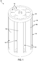
- the assembly 100 includes a housing 102 having a main body 104 and an upper end cap 106.
- the main body 104 includes side walls 108 and a bottom wall 110.
- the main body 104 is shown to include passages 112 between the side walls 108 and passages 114 between the bottom wall 110, and the end cap 106 is shown to include passages 116.
- the passages 112, 114, 116 can permit a carrier fluid to flow in to and out from the assembly 100.
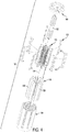
- the non-inventive assembly 100 includes wafers 118 that are formed of a substrate material that produces metal hydride when exposed to a hydrogen-rich carrier fluid.
- the wafers 118 are supported by the housing 102 and arranged so that the carrier fluid can flow over a reaction surface 120 of the wafers 118.
- the metal hydride producing substrate material can be a magnesium-based alloy.
- Other metal hydride producing materials are possible, including, for example but not limited to, Zr-V, Ti-Fe and/or Ti-V alloys.
- the wafers 118 can include a de-activation material on the reaction surface 120.
- the de-activation material can inhibit formation of surface oxide that can impede hydrogen absorption during charging and hydrogen desorption during discharging, which can be referred to as a "poisoning" effect that can occur during repeated use of the wafers 118.
- the de-activation material can be a layer of nickel deposited on the reaction surface 120.
- the layer of nickel can be electrodeposited and have a thickness of between 0.5 and 1.5 ⁇ m, or about 1 ⁇ m.
- the layer of nickel can have a smooth surface finish, e.g., a surface roughness of about 1 ⁇ m R a or less.
- the assembly 100 includes heating elements 122 supported by the housing 102.
- the heating elements 122 are arranged to transfer heat to the wafers 118 to attain an operating temperature suitable for hydrogen charging on the reaction surfaces 120.
- the operating temperature can be between about 200 and 250°C.
- each of the wafers 118 can be a flat plate that is thin-walled, monolithic or solid, rectangular in shape, and spaced apart about a central axis 124 of the assembly 100.
- the wafers 118 can have dimensions of about 75 x 20 x 0.5 mm (length, width, thickness, respectively). Other configurations and dimensions are possible.
- each of the wafers 118 is suspended generally radially about the central axis 124 between inner supports 126 and outer supports, which in the example illustrated are formed by the side walls 108.
- Each of the wafers 118 are shown having an inner edge received in an outwardly facing groove 128 of the respective inner support 126, and an outer edge received in an inwardly facing groove 130 of the respective side wall 108.
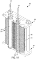
- the assembly 100 includes a central electrical busbar 132 supported by the housing and positioned generally along the central axis 124 ( Figure 4 ).
- the busbar 132 is shown to include longitudinal ridges 134 defining outward faces 136. Electrical power can be provided to the busbar 132 via at least one set of terminals 138.
- the heating elements 122 are connected to and spaced about the busbar 132. In the example illustrated, there are a total of sixteen of the wafers 118 and eight of the heating elements 122. Each of the heating elements 122 is shown received in a respective sleeve 140 and positioned between the reaction surfaces 120 of adjacent ones of the wafers 118 to heat the wafers 118 by thermal radiation.
- the sleeves 140 can serve to keep the heating elements 122 from contacting the wafers 118.
- the sleeves 140 can be made of glass or another transparent or translucent material to allow transmission of radiant heat to the wafers 118.
- the reaction surfaces 120 of adjacent pairs of the wafers 118 can be generally parallel to one another, and the heating element 122 can be approximately equidistant to both of the reaction surfaces 120, which can promote uniform heating of the wafers 118.
- each of the heating elements 122 can take the form of a flat ribbon with a serpentine shape for increasing its electrical resistance and increasing surface area for radiation to the reaction surfaces 120.
- each of the heating elements 122 includes connector mounts 142 at its ends, and the mounts 142 mate with the outward faces 136 of the busbar 132 to establish an electrical connection therewith.
- the sleeves 140 have a T-shaped profile along the inward edges, which are received in a corresponding T-shaped slot in the respective inner support 126.
- outward edges of the sleeves 140 are received in an inwardly facing groove 144 on the side wall 108.
- the housing of the assembly 100 defines at top profile that is generally round in shape, thereby permitting fluid flow around the assemblies in the system 150.
- the assembly 200 includes a housing 202 having a main body 204 and an upper end cap 206.
- the main body 204 includes side walls 208 and a bottom wall 210.
- the main body 204 is shown to include passages 212 between the side walls 208 and passages 214 between the bottom wall 210, and the end cap 206 is shown to include passages 216.
- the passages 212, 214, 216 can permit a carrier fluid to flow in to and out from the assembly 200.
- the non-inventive assembly 200 includes wafers 218 that are formed of a substrate material that produces metal hydride when exposed to a hydrogen-rich carrier fluid.
- the wafers 218 are supported by the housing 202 and arranged so that the carrier fluid can flow over a reaction surface 220 of the wafers 218.
- the metal hydride producing substrate material can be a magnesium-based alloy. Other metal hydride producing materials are possible.
- the wafers 218 can include a de-activation material on the reaction surface 220.
- the de-activation material can inhibit formation of surface oxide that can impede hydrogen absorption during charging and hydrogen desorption during discharging, which can be referred to as a "poisoning" effect that can occur during repeated use of the wafers 218.
- the de-activation material can be a layer of nickel deposited on the reaction surface 220.
- the layer of nickel can be electrodeposited and have a thickness of between 0.5 and 1.5 ⁇ m, or about 1 ⁇ m.
- the layer of nickel can have a smooth surface finish, e.g., a surface roughness of about 1 ⁇ m R a or less.
- the assembly 200 includes heating elements 222 supported by the housing 202.
- the heating elements 222 are arranged to transfer heat to the wafers 218 to attain an operating temperature suitable for hydrogen charging on the reaction surfaces 220.
- the operating temperature can be between about 200 and 250°C.
- each of the wafers 218 can be a flat plate that is thin-walled, monolithic or solid, rectangular in shape, and spaced apart about a central axis 224 of the assembly 200.
- the wafers 218 can have dimensions of about 75 x 20 x 0.5 mm (length, width, thickness, respectively). Other configurations and dimensions are possible.
- the wafers 218 each of the wafers 218 is suspended generally radially about the central axis 224 between inner supports 226 and outer supports, which in the example illustrated are formed by the side walls 208.
- Each of the wafers 218 are shown having an inner edge received in an outwardly facing groove 228 of the respective inner support 226, and an outer edge received in an inwardly facing groove 230 of the respective side wall 208.
- the assembly 200 includes a central electrical busbar 232 supported by the housing and positioned generally along the central axis 224 ( Figure 9 ).
- the busbar 232 is shown to include outward faces 236. Electrical power can be provided to the busbar 232 via at least one set of terminals 238.
- the heating elements 222 are connected to and spaced about the busbar 232. In the example illustrated, there are a total of eighteen of the wafers 218 and twelve of the heating elements 222. Each of the heating elements 222 is shown received in a respective sleeve 240 and positioned between the reaction surfaces 220 of adjacent ones of the wafers 218 to heat the wafers 218 by thermal radiation.
- the sleeves 240 can serve to keep the heating elements 222 from contacting the wafers 218.
- the sleeves 240 can be made of glass or another transparent or translucent material to allow transmission of radiant heat to the wafers 218.
- the reaction surfaces 220 of adjacent pairs of the wafers 218 can be generally parallel to one another, and the heating element 222 can be approximately equidistant to both of the reaction surfaces 220, which can promote uniform heating of the wafers 218.
- each of the heating elements 222 can take the form of a flat ribbon with a serpentine shape for increasing its electrical resistance and increasing surface area for radiation to the reaction surfaces 220.
- each of the heating elements 222 includes connector mounts at its ends, and the mounts mate with the outward faces 236 of the busbar 232 to establish an electrical connection therewith.
- the sleeves 240 have inward edges that are received in a slot in the respective inner support 226. In the example illustrated, outward edges of the sleeves 240 are spaced apart from the side wall 208.
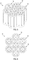
- the housing of the assembly 200 defines at top profile that is generally hexagonal in shape, thereby enabling a relatively close-packed arrangement.
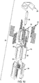
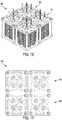
- the assembly 300 includes a housing 302 having a first end panel 304 and a second end panel 306 spaced apart from the first end panel 304.
- the housing 302 includes support rods 308 and stems 310 extending between and connecting the end panels 304, 306.
- the end panels 304, 306 are shown to include passages 314, 316, respectively.
- the passages 314, 316 and spacing around the support rods 308 can permit a carrier fluid to flow in to and out from the assembly 300.
- the assembly 300 includes wafers 318 that are formed of a substrate material that produces metal hydride when exposed to a hydrogen-rich carrier fluid.
- the wafers 318 are supported by the housing 302 and arranged so that the carrier fluid can flow over a reaction surface of the wafers 318.
- the metal hydride producing substrate material can be a magnesium-based alloy. Other metal hydride producing materials are possible.
- the wafers 318 can include a de-activation material on the reaction surface.
- the de-activation material can inhibit formation of surface oxide that can impede hydrogen absorption during charging and hydrogen desorption during discharging, which can be referred to as a "poisoning" effect that can occur during repeated use of the wafers 318.
- the de-activation material can be a layer of nickel deposited on the reaction surface.
- the layer of nickel can be electrodeposited and have a thickness of between 0.5 and 1.5 ⁇ m, or about 1 ⁇ m.
- the layer of nickel can have a smooth surface finish, e.g., a surface roughness of about 1 ⁇ m R a or less.
- the assembly 300 includes heating elements 322 supported by the housing 302.
- the heating elements 322 are arranged to transfer heat to the wafers 318 to attain an operating temperature suitable for hydrogen charging on the reaction surfaces.
- the operating temperature can be between about 200 and 250°C.
- each of the wafers 318 can be a flat disc that is thin-walled, monolithic or solid, and annular in shape.
- the wafers 318 can have dimensions of about 12.5 x 45 x 0.5 mm (inside diameter, outside diameter, thickness, respectively). Other configurations and dimensions are possible.
- each of the wafers 318 includes a central hole, and a respective one of the stems 310 extends through the central hole.
- Hardware 344 applied to the support rods 308 and the stems 310 can exert a clamping force to clamp the wafers 318 between the end panels 304, 306.
- the number of the wafers 318 stacked between the end panels 304, 306 can be varied to vary the overall size of the assembly 300.
- the heating elements 322 are received within a central bore of each of the stems 310 to heat the wafers 318 by thermal conduction.
- Each of the heating elements 322 can take the form of a hermetically-sealed cartridge heater, and electrical power can be provided to the heating elements 322 via terminals 338.
- the wafers 318 are provided in four stacked arrangements, and contact between them can permit thermal conduction between all of the stacks.
- the wafers 318 of one stack partially overlap the wafers 318 of two adjacent stacks, in an alternating or staggered relationship with each, but does not overlap the wafers 318 of the stack that is diagonally opposite and of mirrored formation. With two of the stacks staggered relative to the other two stacks of the wafers 318, the utilization of space can be enhanced so as to reduce the overall dimensions of the assembly 300.
- the housing of the assembly 300 defines at top profile that is generally square or rectangular in shape, thereby enabling a relatively close-packed arrangement.
- a plate or a disc of the metal hydride producing substrate material e.g., a magnesium-based alloy
- the de-activation material e.g. a layer of nickel
- outer surfaces of the plate/disc can be prepared, including, for example, acetone-cleaning by ultrasonic techniques, and then kept immersed in distilled water at room temperature.
- Suitable electrolyte and plating parameters can be selected to electrodeposit, for example, the layer of nickel to a thickness of between 0.5 and 1.5 ⁇ m, or about 1 ⁇ m, and with a surface roughness of about 1 ⁇ m R a or less.
- a nickel sulfamate plating solution can be used with electroplating conditions of about 40 to 60°C solution temperature, a current density of about 2 to 25 A/dm 2 and a pH of about 3.5 to 4.5.
- the hydrogen storage assemblies 100, 200, 300 can be used for storing hydrogen gas for use in transportation or other commercial applications.
- the hydrogen storage assemblies 100, 200, 300 can be used potentially for indoor vehicles as fuel or in confined spaces where insufficient air may pose a problem.
- heat can be transferred to the wafers 118, 218, 318 to attain an operating temperature suitable for hydrogen charging on the reaction surfaces 120, 220, 320, which can be a moderate or low temperature of about 250°C or less.
- a hydrogen-rich carrier fluid can be flowed over the wafers 118, 218, 318 so as to charge hydrogen on the reaction surfaces 120, 220, 320 and thereby store hydrogen.
- the hydrogen-rich carrier fluid can have more than 80% hydrogen gas mixed with an inert gas (e.g., argon or helium).
- the carrier fluid can be delivered to the wafers 118, 218, 318 at a relatively low exposure pressure of about 10 ⁇ 101325 / 760 Pascal (10 Torr) or less.
- a second carrier fluid can be flowed over the wafers 118, 218, 318 to discharge hydrogen from the reaction surfaces 120, 220, 320 and thereby release hydrogen.
- the second carrier fluid that gathers the hydrogen being discharged can be an inert gas.
Landscapes
- Chemical & Material Sciences (AREA)
- Organic Chemistry (AREA)
- Engineering & Computer Science (AREA)
- Inorganic Chemistry (AREA)
- Combustion & Propulsion (AREA)
- Chemical Kinetics & Catalysis (AREA)
- Geology (AREA)
- General Life Sciences & Earth Sciences (AREA)
- Life Sciences & Earth Sciences (AREA)
- Mechanical Engineering (AREA)
- General Engineering & Computer Science (AREA)
- Filling Or Discharging Of Gas Storage Vessels (AREA)
- Hydrogen, Water And Hydrids (AREA)
- Fuel Cell (AREA)
- Electrolytic Production Of Non-Metals, Compounds, Apparatuses Therefor (AREA)
- Non-Volatile Memory (AREA)
Claims (10)
- Wasserstoffspeicheranordnung (300), umfassend:ein Gehäuse (302), das ein erstes und ein zweites Endpaneel (304, 306) umfasst;mindestens einen Wafer (318), der aus einem Substratmaterial gebildet ist, das Metallhydrid erzeugt, wenn es mit einem wasserstoffreichen Trägerfluid in Kontakt gebracht wird, wobei der mindestens eine Wafer (318) durch das Gehäuse (302) gestützt wird und so angeordnet ist, dass das wasserstoffreiche Trägerfluid über eine Reaktionsfläche des mindestens einen Wafers (318) fließen kann; undmindestens ein Heizelement (322), das dafür ausgelegt ist, Wärme zu dem mindestens einen Wafer (318) zu übertragen, um eine Betriebstemperatur zu erreichen, die für die Wasserstoffbeladung der Reaktionsfläche geeignet ist,dadurch gekennzeichnet, dassder mindestens eine Wafer (318) mehrere monolithische Scheibenwafer in mindestens einer gestapelten Anordnung umfasst undScheibenwafer, die zwischen dem ersten und dem zweiten Endpaneel (304, 306) festgeklemmt sind, in einer ersten und einer zweiten gestapelten Anordnung bereitgestellt sind, wobei Scheibenwafer der ersten gestapelten Anordnung in Kontakt mit Scheibenwafern der zweiten gestapelten Anordnung stehen, um eine Wärmeleitung zwischen der ersten und der zweiten gestapelten Anordnung zu ermöglichen, wobei jeder der Scheibenwafer ein mittiges Loch aufweist und das Gehäuse (302) mindestens einen Schaft (310) aufweist, der sich durch die mittigen Löcher der Scheibenwafer zwischen dem ersten und dem zweiten Endpaneel (304, 306) erstreckt.
- Wasserstoffspeicheranordnung (300) nach Anspruch 1, die ein Deaktivierungsmaterial auf der Reaktionsfläche umfasst, um die Bildung von Oberflächenoxid zu hemmen, das die Wasserstoffabsorption während des Ladens und die Wasserstoffdesorption während des Entladens behindert.
- Wasserstoffspeicheranordnung (300) nach Anspruch 2, wobei das Substratmaterial eine Legierung auf Magnesiumbasis ist und das Deaktivierungsmaterial eine auf der Reaktionsfläche abgeschiedene Nickelschicht ist.
- Wasserstoffspeicheranordnung (300) nach Anspruch 3, wobei die Nickelschicht eine Dicke zwischen 0,5 und 1,5 µm oder etwa 1 µm aufweist.
- Wasserstoffspeicheranordnung (300) nach Anspruch 4, wobei die Nickelschicht eine Oberflächenrauigkeit von etwa 1 µm Ra oder weniger aufweist.
- Wasserstoffspeicheranordnung (300) nach einem der vorangehenden Ansprüche, wobei die Endpaneele (304, 306) Durchgänge (314, 316) aufweisen, die ein Fließen des wasserstoffreichen Trägerfluids über die Scheiben ermöglichen.
- Wasserstoffspeicheranordnung (300) nach einem der vorangehenden Ansprüche, wobei die Scheibenwafer der ersten gestapelten Anordnung die Scheibenwafer der zweiten gestapelten Anordnung zueinander versetzt teilweise überlappen.
- Wasserstoffspeicheranordnung (300) nach einem der vorangehenden Ansprüche, wobei das mindestens eine Heizelement (322) ein elektrisches Heizelement umfasst, das in einer mittigen Bohrung des mindestens einen Schafts (310) aufgenommen ist, um die Scheibenwafer durch Wärmeleitung zu erwärmen.
- Wasserstoffspeicheranordnung (300) nach einem der vorangehenden Ansprüche, wobei das Gehäuse (302) mehrere Stützstäbe (308) umfasst, welche die Endpaneele (304, 306) verbinden.
- Wasserstoffspeicheranordnung (300) nach Anspruch 8, wobei die Endpaneele (304, 306) ein oberes Profil der Wasserstoffspeicheranordnung (300) definieren, das allgemein eine quadratische oder rechteckige Form aufweist.
Applications Claiming Priority (2)
| Application Number | Priority Date | Filing Date | Title |
|---|---|---|---|
| US201562264051P | 2015-12-07 | 2015-12-07 | |
| PCT/CA2016/051432 WO2017096474A1 (en) | 2015-12-07 | 2016-12-07 | Hydrogen storage assembly |
Publications (3)
| Publication Number | Publication Date |
|---|---|
| EP3386912A1 EP3386912A1 (de) | 2018-10-17 |
| EP3386912A4 EP3386912A4 (de) | 2019-04-24 |
| EP3386912B1 true EP3386912B1 (de) | 2021-09-01 |
Family
ID=59012408
Family Applications (1)
| Application Number | Title | Priority Date | Filing Date |
|---|---|---|---|
| EP16871863.3A Active EP3386912B1 (de) | 2015-12-07 | 2016-12-07 | Wasserstoffspeicheranordnung |
Country Status (4)
| Country | Link |
|---|---|
| US (2) | US10850979B2 (de) |
| EP (1) | EP3386912B1 (de) |
| CA (2) | CA3215013A1 (de) |
| WO (1) | WO2017096474A1 (de) |
Families Citing this family (4)
| Publication number | Priority date | Publication date | Assignee | Title |
|---|---|---|---|---|
| CA3215013A1 (en) * | 2015-12-07 | 2017-06-15 | Atomic Energy Of Canada Limited / Energie Atomique Du Canada Limitee | Hydrogen storage assembly with wafer formed of a substrate material and heating element |
| KR20200123327A (ko) * | 2019-04-18 | 2020-10-29 | 현대자동차주식회사 | 고체 수소 저장장치 및 이를 포함한 고체 수소 저장모듈 |
| CN109898002B (zh) * | 2019-04-30 | 2020-10-27 | 三桥惠(佛山)新材料有限公司 | 一种镁基储氢合金及其制备方法 |
| CN114151720A (zh) * | 2021-11-24 | 2022-03-08 | 广东电网有限责任公司广州供电局 | 一种新型固态储氢装置 |
Family Cites Families (18)
| Publication number | Priority date | Publication date | Assignee | Title |
|---|---|---|---|---|
| US2890319A (en) | 1957-09-16 | 1959-06-09 | Tung Sol Electric Inc | Fast-heating hydrogen reservoir |
| JPS6145200A (ja) * | 1984-08-10 | 1986-03-05 | Sanyo Electric Co Ltd | 水素貯蔵装置 |
| DE3502311A1 (de) * | 1985-01-21 | 1986-07-24 | Mannesmann AG, 4000 Düsseldorf | Metallhydridspeicher und verfahren zu seiner herstellung |
| US4928496A (en) * | 1989-04-14 | 1990-05-29 | Advanced Materials Corporation | Hydrogen heat pump |
| JP3927318B2 (ja) * | 1998-06-17 | 2007-06-06 | 伸幸 西宮 | 複合水素吸蔵体の製造方法 |
| JP4574783B2 (ja) | 2000-03-07 | 2010-11-04 | 株式会社豊田自動織機 | 水素吸蔵合金タンク |
| US6318453B1 (en) | 2000-04-26 | 2001-11-20 | Energy Conversion Devices, Inc. | Hydrogen cooled hydrogen storage unit having maximized cooling efficiency |
| TW533620B (en) | 2001-07-24 | 2003-05-21 | Asia Pacific Fuel Cell Tech | Metal hydride hydrogen storage canister design and its manufacture |
| US20040142203A1 (en) | 2003-01-07 | 2004-07-22 | Woolley Christopher P. | Hydrogen storage medium |
| JP4119304B2 (ja) * | 2003-05-20 | 2008-07-16 | トヨタ自動車株式会社 | ガス貯蔵装置 |
| CN101203454B (zh) * | 2005-04-22 | 2011-04-20 | 昂斯特罗姆动力公司 | 复合储氢材料及与其相关的方法 |
| JP5056181B2 (ja) * | 2007-06-06 | 2012-10-24 | トヨタ自動車株式会社 | 水素ガス貯蔵装置 |
| JP5050680B2 (ja) * | 2007-06-19 | 2012-10-17 | トヨタ自動車株式会社 | 水素貯蔵タンクの製造方法及び水素貯蔵タンク |
| US8651268B2 (en) | 2007-09-18 | 2014-02-18 | Paul H. Smith, Jr. | Hydrogen energy systems |
| US8778063B2 (en) * | 2009-02-04 | 2014-07-15 | Purdue Research Foundation | Coiled and microchannel heat exchangers for metal hydride storage systems |
| FR2950045B1 (fr) * | 2009-09-17 | 2012-10-12 | Mcphy Energy | Reservoir de stockage et de destockage d'hydrogene et/ou de chaleur |
| FR2992400B1 (fr) * | 2012-06-20 | 2014-08-08 | Centre Nat Rech Scient | Systeme de stockage reversible d'hydrogene dans un materiau sous forme d'hydrure metallique comportant une pluralite de caloducs en contact thermique avec le materiau |
| CA3215013A1 (en) * | 2015-12-07 | 2017-06-15 | Atomic Energy Of Canada Limited / Energie Atomique Du Canada Limitee | Hydrogen storage assembly with wafer formed of a substrate material and heating element |
-
2016
- 2016-12-07 CA CA3215013A patent/CA3215013A1/en active Pending
- 2016-12-07 US US16/060,084 patent/US10850979B2/en active Active
- 2016-12-07 CA CA3007693A patent/CA3007693C/en active Active
- 2016-12-07 EP EP16871863.3A patent/EP3386912B1/de active Active
- 2016-12-07 WO PCT/CA2016/051432 patent/WO2017096474A1/en not_active Ceased
-
2020
- 2020-10-29 US US17/083,806 patent/US11673802B2/en active Active
Also Published As
| Publication number | Publication date |
|---|---|
| CA3007693A1 (en) | 2017-06-15 |
| CA3215013A1 (en) | 2017-06-15 |
| US20210047179A1 (en) | 2021-02-18 |
| CA3007693C (en) | 2025-09-09 |
| US20180354786A1 (en) | 2018-12-13 |
| EP3386912A4 (de) | 2019-04-24 |
| US11673802B2 (en) | 2023-06-13 |
| US10850979B2 (en) | 2020-12-01 |
| EP3386912A1 (de) | 2018-10-17 |
| WO2017096474A1 (en) | 2017-06-15 |
Similar Documents
| Publication | Publication Date | Title |
|---|---|---|
| US11673802B2 (en) | Hydrogen storage assembly | |
| US9379400B2 (en) | Huge stack for flat-tubular solid oxide fuel cell and manufacturing method thereof | |
| EP2112451B1 (de) | Wärmeenergiespeichervorrichtung | |
| US8962202B2 (en) | Internal reforming tubular solid oxide fuel cell stack and manufacturing method therefor | |
| EP2907185B1 (de) | Entwurf bipolarer platten zur verwendung in leitungsgekühlten elektrochemischen zellen | |
| US4583583A (en) | Fuel cell crimp-resistant cooling device with internal coil | |
| KR102123785B1 (ko) | 전기화학 전지에 사용하기 위한 양극판의 디자인 | |
| US4945010A (en) | Cooling assembly for fuel cells | |
| EP3007258A1 (de) | Galvanische stapelanordnung in einem festoxidbrennstoffzellenstromerzeugungssystem | |
| US20160327209A1 (en) | Hydrogen storage tank comprising metal hydrides with heat exchanges | |
| US20190131634A1 (en) | Reversible individual unit for electrolysis or co-electrolysis of water (soec) or for fuel cell (sofc) with operation under pressure and decoupled compressive force | |
| US12017196B2 (en) | Reactor assemblies and methods of performing reactions | |
| JP2021527562A (ja) | 向上されたマイクロチャンネルデバイスまたはメソチャンネルデバイス、及びその添加製造方法 | |
| CN101427413B (zh) | 固体氧化物型燃料电池以及重整器 | |
| JP2020501091A (ja) | 複数のシールを備える水素貯蔵タンク | |
| KR20220107283A (ko) | 셀 유닛 및 셀 스택 | |
| KR100626619B1 (ko) | 촉매가 코팅된 금속 마이크로채널 반응기 제조 방법 및 그반응기 | |
| EP2893588B1 (de) | Brennstoffzelle mit einer protonenaustauschmembran und mit offenzelligem schaumstoff | |
| CN110832686A (zh) | 用于燃料电池堆中热管理的选择性旋转流场 | |
| US20230226513A1 (en) | Reactor Assemblies and Methods of Performing Reactions | |
| JP2010033865A (ja) | 燃料電池 | |
| AU2020240119B2 (en) | Reactor assemblies and methods of performing reactions | |
| Haussener | Integrated solar-driven high-temperature electrolysis operating with concentrated irradiation | |
| JP2014041751A (ja) | 燃料電池モジュール | |
| CN116507407A (zh) | 感应加热微通道和中通道处理系统的方法和装置 |
Legal Events
| Date | Code | Title | Description |
|---|---|---|---|
| STAA | Information on the status of an ep patent application or granted ep patent |
Free format text: STATUS: THE INTERNATIONAL PUBLICATION HAS BEEN MADE |
|
| PUAI | Public reference made under article 153(3) epc to a published international application that has entered the european phase |
Free format text: ORIGINAL CODE: 0009012 |
|
| STAA | Information on the status of an ep patent application or granted ep patent |
Free format text: STATUS: REQUEST FOR EXAMINATION WAS MADE |
|
| 17P | Request for examination filed |
Effective date: 20180612 |
|
| AK | Designated contracting states |
Kind code of ref document: A1 Designated state(s): AL AT BE BG CH CY CZ DE DK EE ES FI FR GB GR HR HU IE IS IT LI LT LU LV MC MK MT NL NO PL PT RO RS SE SI SK SM TR |
|
| AX | Request for extension of the european patent |
Extension state: BA ME |
|
| DAV | Request for validation of the european patent (deleted) | ||
| DAX | Request for extension of the european patent (deleted) | ||
| A4 | Supplementary search report drawn up and despatched |
Effective date: 20190326 |
|
| RIC1 | Information provided on ipc code assigned before grant |
Ipc: C01B 6/00 20060101ALI20190320BHEP Ipc: B01J 20/02 20060101ALI20190320BHEP Ipc: C01B 3/00 20060101AFI20190320BHEP Ipc: C01B 3/56 20060101ALI20190320BHEP |
|
| STAA | Information on the status of an ep patent application or granted ep patent |
Free format text: STATUS: EXAMINATION IS IN PROGRESS |
|
| 17Q | First examination report despatched |
Effective date: 20200604 |
|
| GRAP | Despatch of communication of intention to grant a patent |
Free format text: ORIGINAL CODE: EPIDOSNIGR1 |
|
| STAA | Information on the status of an ep patent application or granted ep patent |
Free format text: STATUS: GRANT OF PATENT IS INTENDED |
|
| INTG | Intention to grant announced |
Effective date: 20210322 |
|
| GRAS | Grant fee paid |
Free format text: ORIGINAL CODE: EPIDOSNIGR3 |
|
| GRAA | (expected) grant |
Free format text: ORIGINAL CODE: 0009210 |
|
| STAA | Information on the status of an ep patent application or granted ep patent |
Free format text: STATUS: THE PATENT HAS BEEN GRANTED |
|
| AK | Designated contracting states |
Kind code of ref document: B1 Designated state(s): AL AT BE BG CH CY CZ DE DK EE ES FI FR GB GR HR HU IE IS IT LI LT LU LV MC MK MT NL NO PL PT RO RS SE SI SK SM TR |
|
| REG | Reference to a national code |
Ref country code: GB Ref legal event code: FG4D |
|
| REG | Reference to a national code |
Ref country code: CH Ref legal event code: EP Ref country code: AT Ref legal event code: REF Ref document number: 1426059 Country of ref document: AT Kind code of ref document: T Effective date: 20210915 |
|
| REG | Reference to a national code |
Ref country code: DE Ref legal event code: R096 Ref document number: 602016063272 Country of ref document: DE |
|
| REG | Reference to a national code |
Ref country code: IE Ref legal event code: FG4D |
|
| REG | Reference to a national code |
Ref country code: LT Ref legal event code: MG9D |
|
| REG | Reference to a national code |
Ref country code: NL Ref legal event code: MP Effective date: 20210901 |
|
| PG25 | Lapsed in a contracting state [announced via postgrant information from national office to epo] |
Ref country code: NO Free format text: LAPSE BECAUSE OF FAILURE TO SUBMIT A TRANSLATION OF THE DESCRIPTION OR TO PAY THE FEE WITHIN THE PRESCRIBED TIME-LIMIT Effective date: 20211201 Ref country code: HR Free format text: LAPSE BECAUSE OF FAILURE TO SUBMIT A TRANSLATION OF THE DESCRIPTION OR TO PAY THE FEE WITHIN THE PRESCRIBED TIME-LIMIT Effective date: 20210901 Ref country code: FI Free format text: LAPSE BECAUSE OF FAILURE TO SUBMIT A TRANSLATION OF THE DESCRIPTION OR TO PAY THE FEE WITHIN THE PRESCRIBED TIME-LIMIT Effective date: 20210901 Ref country code: ES Free format text: LAPSE BECAUSE OF FAILURE TO SUBMIT A TRANSLATION OF THE DESCRIPTION OR TO PAY THE FEE WITHIN THE PRESCRIBED TIME-LIMIT Effective date: 20210901 Ref country code: LT Free format text: LAPSE BECAUSE OF FAILURE TO SUBMIT A TRANSLATION OF THE DESCRIPTION OR TO PAY THE FEE WITHIN THE PRESCRIBED TIME-LIMIT Effective date: 20210901 Ref country code: BG Free format text: LAPSE BECAUSE OF FAILURE TO SUBMIT A TRANSLATION OF THE DESCRIPTION OR TO PAY THE FEE WITHIN THE PRESCRIBED TIME-LIMIT Effective date: 20211201 Ref country code: RS Free format text: LAPSE BECAUSE OF FAILURE TO SUBMIT A TRANSLATION OF THE DESCRIPTION OR TO PAY THE FEE WITHIN THE PRESCRIBED TIME-LIMIT Effective date: 20210901 Ref country code: SE Free format text: LAPSE BECAUSE OF FAILURE TO SUBMIT A TRANSLATION OF THE DESCRIPTION OR TO PAY THE FEE WITHIN THE PRESCRIBED TIME-LIMIT Effective date: 20210901 |
|
| REG | Reference to a national code |
Ref country code: AT Ref legal event code: MK05 Ref document number: 1426059 Country of ref document: AT Kind code of ref document: T Effective date: 20210901 |
|
| PG25 | Lapsed in a contracting state [announced via postgrant information from national office to epo] |
Ref country code: PL Free format text: LAPSE BECAUSE OF FAILURE TO SUBMIT A TRANSLATION OF THE DESCRIPTION OR TO PAY THE FEE WITHIN THE PRESCRIBED TIME-LIMIT Effective date: 20210901 Ref country code: LV Free format text: LAPSE BECAUSE OF FAILURE TO SUBMIT A TRANSLATION OF THE DESCRIPTION OR TO PAY THE FEE WITHIN THE PRESCRIBED TIME-LIMIT Effective date: 20210901 Ref country code: GR Free format text: LAPSE BECAUSE OF FAILURE TO SUBMIT A TRANSLATION OF THE DESCRIPTION OR TO PAY THE FEE WITHIN THE PRESCRIBED TIME-LIMIT Effective date: 20211202 |
|
| PG25 | Lapsed in a contracting state [announced via postgrant information from national office to epo] |
Ref country code: AT Free format text: LAPSE BECAUSE OF FAILURE TO SUBMIT A TRANSLATION OF THE DESCRIPTION OR TO PAY THE FEE WITHIN THE PRESCRIBED TIME-LIMIT Effective date: 20210901 |
|
| PG25 | Lapsed in a contracting state [announced via postgrant information from national office to epo] |
Ref country code: IS Free format text: LAPSE BECAUSE OF FAILURE TO SUBMIT A TRANSLATION OF THE DESCRIPTION OR TO PAY THE FEE WITHIN THE PRESCRIBED TIME-LIMIT Effective date: 20220101 Ref country code: SM Free format text: LAPSE BECAUSE OF FAILURE TO SUBMIT A TRANSLATION OF THE DESCRIPTION OR TO PAY THE FEE WITHIN THE PRESCRIBED TIME-LIMIT Effective date: 20210901 Ref country code: SK Free format text: LAPSE BECAUSE OF FAILURE TO SUBMIT A TRANSLATION OF THE DESCRIPTION OR TO PAY THE FEE WITHIN THE PRESCRIBED TIME-LIMIT Effective date: 20210901 Ref country code: RO Free format text: LAPSE BECAUSE OF FAILURE TO SUBMIT A TRANSLATION OF THE DESCRIPTION OR TO PAY THE FEE WITHIN THE PRESCRIBED TIME-LIMIT Effective date: 20210901 Ref country code: PT Free format text: LAPSE BECAUSE OF FAILURE TO SUBMIT A TRANSLATION OF THE DESCRIPTION OR TO PAY THE FEE WITHIN THE PRESCRIBED TIME-LIMIT Effective date: 20220103 Ref country code: NL Free format text: LAPSE BECAUSE OF FAILURE TO SUBMIT A TRANSLATION OF THE DESCRIPTION OR TO PAY THE FEE WITHIN THE PRESCRIBED TIME-LIMIT Effective date: 20210901 Ref country code: EE Free format text: LAPSE BECAUSE OF FAILURE TO SUBMIT A TRANSLATION OF THE DESCRIPTION OR TO PAY THE FEE WITHIN THE PRESCRIBED TIME-LIMIT Effective date: 20210901 Ref country code: CZ Free format text: LAPSE BECAUSE OF FAILURE TO SUBMIT A TRANSLATION OF THE DESCRIPTION OR TO PAY THE FEE WITHIN THE PRESCRIBED TIME-LIMIT Effective date: 20210901 Ref country code: AL Free format text: LAPSE BECAUSE OF FAILURE TO SUBMIT A TRANSLATION OF THE DESCRIPTION OR TO PAY THE FEE WITHIN THE PRESCRIBED TIME-LIMIT Effective date: 20210901 |
|
| REG | Reference to a national code |
Ref country code: DE Ref legal event code: R097 Ref document number: 602016063272 Country of ref document: DE |
|
| PLBE | No opposition filed within time limit |
Free format text: ORIGINAL CODE: 0009261 |
|
| STAA | Information on the status of an ep patent application or granted ep patent |
Free format text: STATUS: NO OPPOSITION FILED WITHIN TIME LIMIT |
|
| PG25 | Lapsed in a contracting state [announced via postgrant information from national office to epo] |
Ref country code: MC Free format text: LAPSE BECAUSE OF FAILURE TO SUBMIT A TRANSLATION OF THE DESCRIPTION OR TO PAY THE FEE WITHIN THE PRESCRIBED TIME-LIMIT Effective date: 20210901 Ref country code: IT Free format text: LAPSE BECAUSE OF FAILURE TO SUBMIT A TRANSLATION OF THE DESCRIPTION OR TO PAY THE FEE WITHIN THE PRESCRIBED TIME-LIMIT Effective date: 20210901 Ref country code: DK Free format text: LAPSE BECAUSE OF FAILURE TO SUBMIT A TRANSLATION OF THE DESCRIPTION OR TO PAY THE FEE WITHIN THE PRESCRIBED TIME-LIMIT Effective date: 20210901 |
|
| REG | Reference to a national code |
Ref country code: CH Ref legal event code: PL |
|
| 26N | No opposition filed |
Effective date: 20220602 |
|
| PG25 | Lapsed in a contracting state [announced via postgrant information from national office to epo] |
Ref country code: SI Free format text: LAPSE BECAUSE OF FAILURE TO SUBMIT A TRANSLATION OF THE DESCRIPTION OR TO PAY THE FEE WITHIN THE PRESCRIBED TIME-LIMIT Effective date: 20210901 |
|
| REG | Reference to a national code |
Ref country code: BE Ref legal event code: MM Effective date: 20211231 |
|
| PG25 | Lapsed in a contracting state [announced via postgrant information from national office to epo] |
Ref country code: LU Free format text: LAPSE BECAUSE OF NON-PAYMENT OF DUE FEES Effective date: 20211207 Ref country code: IE Free format text: LAPSE BECAUSE OF NON-PAYMENT OF DUE FEES Effective date: 20211207 |
|
| PG25 | Lapsed in a contracting state [announced via postgrant information from national office to epo] |
Ref country code: BE Free format text: LAPSE BECAUSE OF NON-PAYMENT OF DUE FEES Effective date: 20211231 |
|
| PG25 | Lapsed in a contracting state [announced via postgrant information from national office to epo] |
Ref country code: LI Free format text: LAPSE BECAUSE OF NON-PAYMENT OF DUE FEES Effective date: 20211231 Ref country code: CH Free format text: LAPSE BECAUSE OF NON-PAYMENT OF DUE FEES Effective date: 20211231 |
|
| PG25 | Lapsed in a contracting state [announced via postgrant information from national office to epo] |
Ref country code: HU Free format text: LAPSE BECAUSE OF FAILURE TO SUBMIT A TRANSLATION OF THE DESCRIPTION OR TO PAY THE FEE WITHIN THE PRESCRIBED TIME-LIMIT; INVALID AB INITIO Effective date: 20161207 |
|
| PG25 | Lapsed in a contracting state [announced via postgrant information from national office to epo] |
Ref country code: CY Free format text: LAPSE BECAUSE OF FAILURE TO SUBMIT A TRANSLATION OF THE DESCRIPTION OR TO PAY THE FEE WITHIN THE PRESCRIBED TIME-LIMIT Effective date: 20210901 |
|
| PG25 | Lapsed in a contracting state [announced via postgrant information from national office to epo] |
Ref country code: MK Free format text: LAPSE BECAUSE OF FAILURE TO SUBMIT A TRANSLATION OF THE DESCRIPTION OR TO PAY THE FEE WITHIN THE PRESCRIBED TIME-LIMIT Effective date: 20210901 |
|
| PG25 | Lapsed in a contracting state [announced via postgrant information from national office to epo] |
Ref country code: MT Free format text: LAPSE BECAUSE OF FAILURE TO SUBMIT A TRANSLATION OF THE DESCRIPTION OR TO PAY THE FEE WITHIN THE PRESCRIBED TIME-LIMIT Effective date: 20210901 |
|
| PG25 | Lapsed in a contracting state [announced via postgrant information from national office to epo] |
Ref country code: TR Free format text: LAPSE BECAUSE OF FAILURE TO SUBMIT A TRANSLATION OF THE DESCRIPTION OR TO PAY THE FEE WITHIN THE PRESCRIBED TIME-LIMIT Effective date: 20210901 |
|
| PGFP | Annual fee paid to national office [announced via postgrant information from national office to epo] |
Ref country code: DE Payment date: 20251215 Year of fee payment: 10 |
|
| PGFP | Annual fee paid to national office [announced via postgrant information from national office to epo] |
Ref country code: GB Payment date: 20251130 Year of fee payment: 10 |
|
| PGFP | Annual fee paid to national office [announced via postgrant information from national office to epo] |
Ref country code: FR Payment date: 20251215 Year of fee payment: 10 |