EP3386641B1 - Vorrichtung zur zerstäubung eines fluids - Google Patents
Vorrichtung zur zerstäubung eines fluids Download PDFInfo
- Publication number
- EP3386641B1 EP3386641B1 EP15808387.3A EP15808387A EP3386641B1 EP 3386641 B1 EP3386641 B1 EP 3386641B1 EP 15808387 A EP15808387 A EP 15808387A EP 3386641 B1 EP3386641 B1 EP 3386641B1
- Authority
- EP
- European Patent Office
- Prior art keywords
- fluid
- atomized
- outlet
- inlet
- chamber
- Prior art date
- Legal status (The legal status is an assumption and is not a legal conclusion. Google has not performed a legal analysis and makes no representation as to the accuracy of the status listed.)
- Active
Links
Images

Classifications
-
- B—PERFORMING OPERATIONS; TRANSPORTING
- B05—SPRAYING OR ATOMISING IN GENERAL; APPLYING FLUENT MATERIALS TO SURFACES, IN GENERAL
- B05B—SPRAYING APPARATUS; ATOMISING APPARATUS; NOZZLES
- B05B1/00—Nozzles, spray heads or other outlets, with or without auxiliary devices such as valves, heating means
- B05B1/02—Nozzles, spray heads or other outlets, with or without auxiliary devices such as valves, heating means designed to produce a jet, spray, or other discharge of particular shape or nature, e.g. in single drops, or having an outlet of particular shape
- B05B1/08—Nozzles, spray heads or other outlets, with or without auxiliary devices such as valves, heating means designed to produce a jet, spray, or other discharge of particular shape or nature, e.g. in single drops, or having an outlet of particular shape of pulsating nature, e.g. delivering liquid in successive separate quantities
-
- F—MECHANICAL ENGINEERING; LIGHTING; HEATING; WEAPONS; BLASTING
- F23—COMBUSTION APPARATUS; COMBUSTION PROCESSES
- F23D—BURNERS
- F23D2900/00—Special features of, or arrangements for burners using fluid fuels or solid fuels suspended in a carrier gas
- F23D2900/14—Special features of gas burners
- F23D2900/14482—Burner nozzles incorporating a fluidic oscillator
Definitions
- the invention relates to a device for atomizing a fluid, a use of such device for e.g. injection of combustible, spraying, fire extinction, cooling, heating and heat exchange and a method for atomizing a fluid.
- a device for atomizing a fluid is presented.
- the present invention provides a device for atomizing a fluid, wherein the design and/or mechanical structure of the device is simple and therefore easy and cheap to manufacture, to maintain, to repair and to use.
- the device can be designed without moving parts, which further increases the benefits in view of manufacturing and handling.
- the device is a passive fluidic device which is only driven by the provided pressurized gas.
- the first and second fluids can be automatically sucked in the chamber from preferably unpressurized container(s) by means of the pressurized gas provided by the pressure inlet.
- the first and second fluids are then automatically atomized in the chamber, again by means of the pressurized gas.
- the pressurized gas might be e.g. air with 1 bar excess pressure, different water solutions at the like.
- the first and second fluids can be outputted or released alternating or alternatively through the first outlet and the second outlet by means of the construction of the chamber as fluidic oscillator.
- oscillations are produced purely by fluid-dynamic instabilities within the chamber.
- the fluidic oscillator might be a bi-stable fluidic oscillator which is a device designed and formed to alternating attach the pressurized gas to a chamber wall next to the first fluid inlet or to the second fluid inlet, so that the pressurized gas alternating draws the first fluid and the second fluid into the chamber and outputs the atomized first fluid and the atomized second fluid alternating or alternatively through the first outlet and the second outlet.
- a bi-stable fluidic oscillator which is a device designed and formed to alternating attach the pressurized gas to a chamber wall next to the first fluid inlet or to the second fluid inlet, so that the pressurized gas alternating draws the first fluid and the second fluid into the chamber and outputs the atomized first fluid and the atomized second fluid alternating or alternatively through the first outlet and the second outlet.
- the released atomized first fluid and the atomized second fluid are pulsed from the first and the second outlets or orifices.
- the first and the second outlets can be alternating at high and variable frequency of e.g. up to 250 Hz.
- the first and the second outlets can be alternating to produce coherent turbulent structures, such that e.g. heat can be carried away efficiently.
- the device according to the invention can be designed to be very compact and small, even quasi 2D is possible, and can therefore be designed to be incorporated in a small installation space.
- the device for atomizing a fluid can also be easily scaled in a wide range for applications with different requirements of e.g. installation space, output pressure, output volume, output speed and the like. For example, sizes from 30 cm to less than 1 cm are possible.
- the device for atomizing a fluid according to the invention allows using either gas or liquid and allows a generation of very fine particles e.g. in the range of 100 nm to 0.5 mm. Further, a good degree of mixing can be achieved without mixing the fluids in advance.
- the fluidic oscillator is configured to mix the first atomized fluid and the second atomized fluid by alternating outputting the atomized first fluid and the atomized second fluid. In an example, the fluidic oscillator is configured to mix the first atomized fluid and the second atomized fluid in the chamber before alternating outputting. In an example, the mixing of the first atomized fluid and the second atomized fluid is based on turbulences in the first atomized fluid and the second atomized fluid. In an example, the first outlet and the second outlet are configured to further atomize the first fluid and the second fluid.
- the device for atomizing a fluid according to the invention can be used for injection and fine distribution of combustible for efficient burning, for spraying one- or two-component paint or varnish, for spraying with a catalytic component for e.g. large surfaces, for fire extinction in e.g. cargo and/or cabin compartments of an aircraft or vehicle with one- or two-component fire extinguisher, for cooling and temperature reduction of e.g. exhaust plume, hot spots and/or surfaces, for heat exchange and the like.
- a catalytic component for e.g. large surfaces, for fire extinction in e.g. cargo and/or cabin compartments of an aircraft or vehicle with one- or two-component fire extinguisher, for cooling and temperature reduction of e.g. exhaust plume, hot spots and/or surfaces, for heat exchange and the like.
- a geometry of at least one of a group of the pressure inlet, the first fluid inlet, the second fluid inlet, the first outlet and the second outlet is variable to control a frequency of outputting the atomized first fluid and/or a frequency of outputting the atomized second fluid.
- a geometry of at least one of the group of the pressure inlet, the first fluid inlet and the second fluid inlet is variable to control the atomization.
- the device according to the invention may comprise more than two fluid inlets, e.g. a third fluid inlet leading into the chamber.
- the fluidic oscillator might then be a tri-stable fluidic oscillator configured to alternating attach the pressurized gas to the first, second or to third fluid inlet so that the pressurized gas alternating draws the first, second or to third fluids into the chamber, atomizes the first, second or to third fluids and outputs the atomized first, second or to third fluid alternating through the first outlet and the second outlet.
- a third outlet can be provided to output the first, second or to third fluids through the first, second or to third outlets.
- the first outlet and/or the second outlet are a nozzle designed based on the application field of the device according to the invention.
- the components of the device according to the invention can be made from metals, polymers and/or many other materials, according to temperature requirements.
- a use of a device as described above is presented for injection of combustible, spraying, fire extinction, cooling, heating, heat exchange and/or the like.
- Figure 1 shows schematically and exemplarily an isometric view of a device 10 for atomizing a fluid.
- the device 10 for atomizing a fluid comprises a top part 1, a bottom part 2, a pressure inlet 13 for providing a pressurized gas 23, a first fluid inlet 11 for providing a first fluid 21, a second fluid inlet 12 for providing a second fluid 22, a chamber 14, a first outlet 15, and a second outlet 16.
- Figure 2 shows schematically and exemplarily a plan view of the bottom part 2 of the device 10 shown in Figure 1 .
- the pressure inlet 13, the first fluid inlet 11 and the second fluid inlet 12 lead into the chamber 14 and the first outlet 15 and the second outlet 16 leave the chamber 14.
- the pressure inlet 13, the first fluid inlet 11 and the second fluid inlet 12 are designed such that the pressurized gas 23 provided by the pressure inlet 13 draws the first fluid 21 and the second fluid 22 into the chamber 14.
- the chamber 14 is part of a fluidic oscillator to alternating attach the pressurized gas 23 to the first fluid inlet 11 or to the second fluid inlet 12, so that the pressurized gas 23 alternating draws the first fluid 21 and the second fluid 22 into the chamber 14, atomizes the first fluid 21 and the second fluid 22 and outputs the atomized first fluid 21 and the atomized second fluid 22 alternating through the first outlet 15 and the second outlet 16.
- the first fluid 21 might be a gas or a liquid.
- the second fluid 22 might also be a gas or a liquid.
- the first outlet 15 and the second outlet 16 are here nozzles designed based on the particular application field of the device 10.
- the device 10 is designed without any moving parts, which means the device 10 is a passive fluidic device 10 which is only driven by the pressurized gas 23 provided by the pressure inlet 13.
- the first and second fluids are first automatically sucked from unpressurized containers into the chamber 14 and then therein automatically atomized by means of the pressurized gas 23.
- the pressurized gas 23 is e.g. air with about 1 bar excess pressure.
- the released atomized first fluid 21 and the atomized second fluid 22 are pulsed from the first and the second outlets 16 or orifices.
- the first and the second fluid 22 are here different.
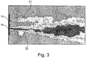
- the fluidic oscillator then mixes the first atomized fluid and the second atomized fluid by alternating outputting the atomized first fluid 21 and the atomized second fluid 22 as shown in Figure 3 .
- the fluidic oscillator further mixes the first atomized fluid and the second atomized fluid in the chamber 14 before alternating outputting.
- a geometry of the pressure inlet 13, the first fluid inlet 11, the second fluid inlet 12, the first outlet 15 and/or the second outlet 16 may be variable to control a frequency of outputting the atomized first fluid 21 and/or a frequency of outputting the atomized second fluid 22. Also a geometry of the pressure inlet 13, the first fluid inlet 11 and/or the second fluid inlet 12 may be variable to control the atomization.
- Figure 4 shows schematically and exemplarily a method for atomizing a fluid which is not part of the invention as claimed.
Landscapes
- Nozzles (AREA)
Claims (10)
- Vorrichtung (10) zur Zerstäubung eines Fluids, umfassend:- einen Druckeinlass (13) zum Bereitstellen eines druckbeaufschlagten Gases (23),- einen ersten Fluideinlass (11) zum Bereitstellen eines ersten Fluids (21),- einen zweiten Fluideinlass (12) zum Bereitstellen eines zweiten Fluids (22),- eine Kammer (14),- einen ersten Auslass (15), und- einen zweiten Auslass (16),wobei der Druckeinlass (13), der erste Fluideinlass (11) und der zweite Fluideinlass (12) in die Kammer (14) führen und der erste Auslass (15) und der zweite Auslass (16) die Kammer (14) verlassen,
wobei der Druckeinlass (13), der erste Fluideinlass (11) und der zweite Fluideinlass (12) so ausgestaltet sind, dass das druckbeaufschlagte Gas (23), welches durch den Druckeinlass (13) bereitgestellt wird, das erste Fluid und das zweite Fluid (22) in die Kammer (14) zieht,
wobei die Kammer (14) Teil eines fluidtechnischen Oszillators ist, der ausgestaltet ist, um alternierend das druckbeaufschlagte Gas (23) an dem ersten Fluideinlass (11) oder an dem zweiten Fluideinlass (12) anzubringen, so dass das druckbeaufschlagte Gas (23) alternierend das erste Fluid und das zweite Fluid (22) in die Kammer (14) zieht, das erste Fluid (21) und das zweite Fluid (22) zerstäubt und das zerstäubte erste Fluid (21) und das zerstäubte zweite Fluid (22) alternierend durch den ersten Auslass (15) und den zweiten Auslass (16) ausgibt,
dadurch gekennzeichnet, dass eine Geometrie von mindestens einer von einer Gruppe des Druckeinlasses (13), des ersten Fluideinlasses (11), des zweiten Fluideinlasses (12) variabel ist, um die Zerstäubung und/oder eine Frequenz der Ausgabe des zerstäubten ersten Fluids (21) und/oder eine Frequenz der Ausgabe des zerstäubten zweiten Fluids (22) zu steuern. - Vorrichtung (10) nach Anspruch 1, wobei der fluidtechnische Oszillator ausgestaltet ist, um das erste zerstäubte Fluid und das zweite zerstäubte Fluid in der Kammer (14) zu mischen.
- Vorrichtung (10) nach einem der vorhergehenden Ansprüche, wobei der erste Auslass (15) und der zweite Auslass (16) ausgestaltet sind, um das erste Fluid (21) und das zweite Fluid (22) weiter zu zerstäuben.
- Vorrichtung (10) nach einem der vorhergehenden Ansprüche, des Weiteren umfassend einen nicht druckbeaufschlagten Behälter für das erste Fluid (21) und das zweite Fluid (22).
- Vorrichtung (10) nach einem der vorhergehenden Ansprüche, wobei eine Geometrie von mindestens einem von einer Gruppe des ersten Auslasses (15) und des zweiten Auslasses (16) variabel ist, um eine Frequenz des Ausgebens des zerstäubten ersten Fluids (21) und/oder eine Frequenz des Ausgebens des zerstäubten zweiten Fluids (22) zu steuern.
- Verwendung einer Vorrichtung (10) nach einem der vorhergehenden Ansprüche für eines aus einer Gruppe von Einspritzung eines Brennstoffs, Sprühen, Feuerlöschen, Kühlen, Heizen und Wärmetausch.
- Verwendung nach Anspruch 6, wobei das erste Fluid (21) das gleiche wie das zweite Fluid (22) ist.
- Verwendung nach Anspruch 6, wobei das zweite Fluid (22) sich von dem ersten Fluid (21) unterscheidet, und wobei der fluidtechnische Oszillator ausgestaltet ist, um das erste zerstäubte Fluid und das zweite zerstäubte Fluid zu mischen, indem das Ausgeben des zerstäubten ersten Fluids (21) und des zerstäubten zweiten Fluids (22) alterniert wird.
- Verwendung nach Anspruch 8, wobei das Mischen des ersten zerstäubten Fluids und des zweiten zerstäubten Fluids auf Turbulenzen in dem ersten zerstäubten Fluid und dem zweiten zerstäubten Fluid basiert.
- Verwendung nach einem der vorhergehenden Ansprüche 6 bis 9, wobei die Vorrichtung (10) nur durch das bereitgestellte druckbeaufschlagte Gas (23) angetrieben wird.
Applications Claiming Priority (1)
| Application Number | Priority Date | Filing Date | Title |
|---|---|---|---|
| PCT/EP2015/079299 WO2017097365A1 (en) | 2015-12-10 | 2015-12-10 | Device for atomizing a fluid |
Publications (2)
| Publication Number | Publication Date |
|---|---|
| EP3386641A1 EP3386641A1 (de) | 2018-10-17 |
| EP3386641B1 true EP3386641B1 (de) | 2020-07-01 |
Family
ID=54849619
Family Applications (1)
| Application Number | Title | Priority Date | Filing Date |
|---|---|---|---|
| EP15808387.3A Active EP3386641B1 (de) | 2015-12-10 | 2015-12-10 | Vorrichtung zur zerstäubung eines fluids |
Country Status (2)
| Country | Link |
|---|---|
| EP (1) | EP3386641B1 (de) |
| WO (1) | WO2017097365A1 (de) |
Family Cites Families (4)
| Publication number | Priority date | Publication date | Assignee | Title |
|---|---|---|---|---|
| US3388862A (en) * | 1965-12-01 | 1968-06-18 | Exxon Research Engineering Co | Pneumatic control of furnaces |
| US3748852A (en) * | 1969-12-05 | 1973-07-31 | L Cole | Self-stabilizing pressure compensated injector |
| DE4439437A1 (de) * | 1994-11-04 | 1996-05-09 | Stihl Maschf Andreas | Hochdruckdüse für ein Hochdruckreinigungsgerät |
| US6581856B1 (en) * | 1998-11-06 | 2003-06-24 | Bowles Fluidics Corporation | Fluid mixer |
-
2015
- 2015-12-10 WO PCT/EP2015/079299 patent/WO2017097365A1/en not_active Ceased
- 2015-12-10 EP EP15808387.3A patent/EP3386641B1/de active Active
Non-Patent Citations (1)
| Title |
|---|
| None * |
Also Published As
| Publication number | Publication date |
|---|---|
| EP3386641A1 (de) | 2018-10-17 |
| WO2017097365A1 (en) | 2017-06-15 |
Similar Documents
| Publication | Publication Date | Title |
|---|---|---|
| EP1813352B1 (de) | Vorrichtung zur druckluftzerstäubung von flüssigkeiten unter verwendung eines implosiven gasstroms | |
| RU2137039C1 (ru) | Жидкостная форсунка | |
| RU2461427C1 (ru) | Форсунка кочетова для распыливания жидкостей | |
| RU2416445C1 (ru) | Жидкостная форсунка | |
| RU2469758C1 (ru) | Жидкостная форсунка кочетова | |
| EP1718413A1 (de) | Verfahren und vorrichtung zur erzeugung von nebel | |
| MX2007015843A (es) | Emisor de baja presion de alta velocidad. | |
| RU2501586C1 (ru) | Форсунка с завихрителем двойной крутки потока | |
| JPS61138559A (ja) | 超音波噴射ノズル用振動子 | |
| RU2416442C1 (ru) | Форсунка кочетова | |
| JPS61259782A (ja) | 多段エツジ部を有する超音波霧化用振動子 | |
| US10286240B2 (en) | Automatic nozzle for firefighting systems | |
| KR101732643B1 (ko) | 액체 미립화 노즐 어셈블리 | |
| RU2473396C1 (ru) | Пневматическая форсунка кочетова | |
| Mahrukh et al. | Effects of angular injection, and effervescent atomization on high-velocity suspension flame spray process | |
| JP2015078775A5 (de) | ||
| EP3204169B1 (de) | Verfahren und vorrichtung zur zerstäubung von flüssigkeiten | |
| EP3386641A1 (de) | Vorrichtung zur zerstäubung eines fluids | |
| CN203030456U (zh) | 一种雾化喷嘴装置 | |
| Khatami et al. | Modeling of aerosol spray characteristics for synthesis of sensor thin film from solution | |
| TWI270412B (en) | Integrated micro-mixing atomization system | |
| RU2553954C1 (ru) | Форсунка кочетова | |
| Naz et al. | Spatio-temporal droplet size statistics in developing spray of starchy solution | |
| TWI587925B (zh) | 多激擾靜電輔助噴霧造粒噴嘴裝置 | |
| Mlkvik et al. | Comparison of Y-jet and OIL effervescent atomizers based on internal and external two-phase flow characteristics |
Legal Events
| Date | Code | Title | Description |
|---|---|---|---|
| STAA | Information on the status of an ep patent application or granted ep patent |
Free format text: STATUS: THE INTERNATIONAL PUBLICATION HAS BEEN MADE |
|
| PUAI | Public reference made under article 153(3) epc to a published international application that has entered the european phase |
Free format text: ORIGINAL CODE: 0009012 |
|
| STAA | Information on the status of an ep patent application or granted ep patent |
Free format text: STATUS: REQUEST FOR EXAMINATION WAS MADE |
|
| 17P | Request for examination filed |
Effective date: 20180418 |
|
| AK | Designated contracting states |
Kind code of ref document: A1 Designated state(s): AL AT BE BG CH CY CZ DE DK EE ES FI FR GB GR HR HU IE IS IT LI LT LU LV MC MK MT NL NO PL PT RO RS SE SI SK SM TR |
|
| AX | Request for extension of the european patent |
Extension state: BA ME |
|
| DAV | Request for validation of the european patent (deleted) | ||
| DAX | Request for extension of the european patent (deleted) | ||
| GRAP | Despatch of communication of intention to grant a patent |
Free format text: ORIGINAL CODE: EPIDOSNIGR1 |
|
| STAA | Information on the status of an ep patent application or granted ep patent |
Free format text: STATUS: GRANT OF PATENT IS INTENDED |
|
| INTG | Intention to grant announced |
Effective date: 20200120 |
|
| GRAS | Grant fee paid |
Free format text: ORIGINAL CODE: EPIDOSNIGR3 |
|
| GRAA | (expected) grant |
Free format text: ORIGINAL CODE: 0009210 |
|
| STAA | Information on the status of an ep patent application or granted ep patent |
Free format text: STATUS: THE PATENT HAS BEEN GRANTED |
|
| AK | Designated contracting states |
Kind code of ref document: B1 Designated state(s): AL AT BE BG CH CY CZ DE DK EE ES FI FR GB GR HR HU IE IS IT LI LT LU LV MC MK MT NL NO PL PT RO RS SE SI SK SM TR |
|
| REG | Reference to a national code |
Ref country code: AT Ref legal event code: REF Ref document number: 1285656 Country of ref document: AT Kind code of ref document: T Effective date: 20200715 Ref country code: CH Ref legal event code: EP |
|
| REG | Reference to a national code |
Ref country code: IE Ref legal event code: FG4D |
|
| REG | Reference to a national code |
Ref country code: DE Ref legal event code: R096 Ref document number: 602015055162 Country of ref document: DE |
|
| REG | Reference to a national code |
Ref country code: LT Ref legal event code: MG4D |
|
| PG25 | Lapsed in a contracting state [announced via postgrant information from national office to epo] |
Ref country code: BG Free format text: LAPSE BECAUSE OF FAILURE TO SUBMIT A TRANSLATION OF THE DESCRIPTION OR TO PAY THE FEE WITHIN THE PRESCRIBED TIME-LIMIT Effective date: 20201001 |
|
| REG | Reference to a national code |
Ref country code: NL Ref legal event code: MP Effective date: 20200701 |
|
| REG | Reference to a national code |
Ref country code: AT Ref legal event code: MK05 Ref document number: 1285656 Country of ref document: AT Kind code of ref document: T Effective date: 20200701 |
|
| PG25 | Lapsed in a contracting state [announced via postgrant information from national office to epo] |
Ref country code: GR Free format text: LAPSE BECAUSE OF FAILURE TO SUBMIT A TRANSLATION OF THE DESCRIPTION OR TO PAY THE FEE WITHIN THE PRESCRIBED TIME-LIMIT Effective date: 20201002 Ref country code: FI Free format text: LAPSE BECAUSE OF FAILURE TO SUBMIT A TRANSLATION OF THE DESCRIPTION OR TO PAY THE FEE WITHIN THE PRESCRIBED TIME-LIMIT Effective date: 20200701 Ref country code: CZ Free format text: LAPSE BECAUSE OF FAILURE TO SUBMIT A TRANSLATION OF THE DESCRIPTION OR TO PAY THE FEE WITHIN THE PRESCRIBED TIME-LIMIT Effective date: 20200701 Ref country code: ES Free format text: LAPSE BECAUSE OF FAILURE TO SUBMIT A TRANSLATION OF THE DESCRIPTION OR TO PAY THE FEE WITHIN THE PRESCRIBED TIME-LIMIT Effective date: 20200701 Ref country code: HR Free format text: LAPSE BECAUSE OF FAILURE TO SUBMIT A TRANSLATION OF THE DESCRIPTION OR TO PAY THE FEE WITHIN THE PRESCRIBED TIME-LIMIT Effective date: 20200701 Ref country code: LT Free format text: LAPSE BECAUSE OF FAILURE TO SUBMIT A TRANSLATION OF THE DESCRIPTION OR TO PAY THE FEE WITHIN THE PRESCRIBED TIME-LIMIT Effective date: 20200701 Ref country code: PT Free format text: LAPSE BECAUSE OF FAILURE TO SUBMIT A TRANSLATION OF THE DESCRIPTION OR TO PAY THE FEE WITHIN THE PRESCRIBED TIME-LIMIT Effective date: 20201102 Ref country code: AT Free format text: LAPSE BECAUSE OF FAILURE TO SUBMIT A TRANSLATION OF THE DESCRIPTION OR TO PAY THE FEE WITHIN THE PRESCRIBED TIME-LIMIT Effective date: 20200701 Ref country code: NO Free format text: LAPSE BECAUSE OF FAILURE TO SUBMIT A TRANSLATION OF THE DESCRIPTION OR TO PAY THE FEE WITHIN THE PRESCRIBED TIME-LIMIT Effective date: 20201001 Ref country code: SE Free format text: LAPSE BECAUSE OF FAILURE TO SUBMIT A TRANSLATION OF THE DESCRIPTION OR TO PAY THE FEE WITHIN THE PRESCRIBED TIME-LIMIT Effective date: 20200701 |
|
| PG25 | Lapsed in a contracting state [announced via postgrant information from national office to epo] |
Ref country code: IS Free format text: LAPSE BECAUSE OF FAILURE TO SUBMIT A TRANSLATION OF THE DESCRIPTION OR TO PAY THE FEE WITHIN THE PRESCRIBED TIME-LIMIT Effective date: 20201101 Ref country code: PL Free format text: LAPSE BECAUSE OF FAILURE TO SUBMIT A TRANSLATION OF THE DESCRIPTION OR TO PAY THE FEE WITHIN THE PRESCRIBED TIME-LIMIT Effective date: 20200701 Ref country code: RS Free format text: LAPSE BECAUSE OF FAILURE TO SUBMIT A TRANSLATION OF THE DESCRIPTION OR TO PAY THE FEE WITHIN THE PRESCRIBED TIME-LIMIT Effective date: 20200701 Ref country code: LV Free format text: LAPSE BECAUSE OF FAILURE TO SUBMIT A TRANSLATION OF THE DESCRIPTION OR TO PAY THE FEE WITHIN THE PRESCRIBED TIME-LIMIT Effective date: 20200701 |
|
| PG25 | Lapsed in a contracting state [announced via postgrant information from national office to epo] |
Ref country code: NL Free format text: LAPSE BECAUSE OF FAILURE TO SUBMIT A TRANSLATION OF THE DESCRIPTION OR TO PAY THE FEE WITHIN THE PRESCRIBED TIME-LIMIT Effective date: 20200701 |
|
| REG | Reference to a national code |
Ref country code: DE Ref legal event code: R097 Ref document number: 602015055162 Country of ref document: DE |
|
| PG25 | Lapsed in a contracting state [announced via postgrant information from national office to epo] |
Ref country code: SM Free format text: LAPSE BECAUSE OF FAILURE TO SUBMIT A TRANSLATION OF THE DESCRIPTION OR TO PAY THE FEE WITHIN THE PRESCRIBED TIME-LIMIT Effective date: 20200701 Ref country code: RO Free format text: LAPSE BECAUSE OF FAILURE TO SUBMIT A TRANSLATION OF THE DESCRIPTION OR TO PAY THE FEE WITHIN THE PRESCRIBED TIME-LIMIT Effective date: 20200701 Ref country code: EE Free format text: LAPSE BECAUSE OF FAILURE TO SUBMIT A TRANSLATION OF THE DESCRIPTION OR TO PAY THE FEE WITHIN THE PRESCRIBED TIME-LIMIT Effective date: 20200701 Ref country code: IT Free format text: LAPSE BECAUSE OF FAILURE TO SUBMIT A TRANSLATION OF THE DESCRIPTION OR TO PAY THE FEE WITHIN THE PRESCRIBED TIME-LIMIT Effective date: 20200701 Ref country code: DK Free format text: LAPSE BECAUSE OF FAILURE TO SUBMIT A TRANSLATION OF THE DESCRIPTION OR TO PAY THE FEE WITHIN THE PRESCRIBED TIME-LIMIT Effective date: 20200701 |
|
| PLBE | No opposition filed within time limit |
Free format text: ORIGINAL CODE: 0009261 |
|
| STAA | Information on the status of an ep patent application or granted ep patent |
Free format text: STATUS: NO OPPOSITION FILED WITHIN TIME LIMIT |
|
| PG25 | Lapsed in a contracting state [announced via postgrant information from national office to epo] |
Ref country code: AL Free format text: LAPSE BECAUSE OF FAILURE TO SUBMIT A TRANSLATION OF THE DESCRIPTION OR TO PAY THE FEE WITHIN THE PRESCRIBED TIME-LIMIT Effective date: 20200701 |
|
| 26N | No opposition filed |
Effective date: 20210406 |
|
| PG25 | Lapsed in a contracting state [announced via postgrant information from national office to epo] |
Ref country code: SK Free format text: LAPSE BECAUSE OF FAILURE TO SUBMIT A TRANSLATION OF THE DESCRIPTION OR TO PAY THE FEE WITHIN THE PRESCRIBED TIME-LIMIT Effective date: 20200701 |
|
| REG | Reference to a national code |
Ref country code: CH Ref legal event code: PL |
|
| PG25 | Lapsed in a contracting state [announced via postgrant information from national office to epo] |
Ref country code: MC Free format text: LAPSE BECAUSE OF FAILURE TO SUBMIT A TRANSLATION OF THE DESCRIPTION OR TO PAY THE FEE WITHIN THE PRESCRIBED TIME-LIMIT Effective date: 20200701 Ref country code: SI Free format text: LAPSE BECAUSE OF FAILURE TO SUBMIT A TRANSLATION OF THE DESCRIPTION OR TO PAY THE FEE WITHIN THE PRESCRIBED TIME-LIMIT Effective date: 20200701 |
|
| REG | Reference to a national code |
Ref country code: BE Ref legal event code: MM Effective date: 20201231 |
|
| PG25 | Lapsed in a contracting state [announced via postgrant information from national office to epo] |
Ref country code: LU Free format text: LAPSE BECAUSE OF NON-PAYMENT OF DUE FEES Effective date: 20201210 Ref country code: IE Free format text: LAPSE BECAUSE OF NON-PAYMENT OF DUE FEES Effective date: 20201210 |
|
| PG25 | Lapsed in a contracting state [announced via postgrant information from national office to epo] |
Ref country code: LI Free format text: LAPSE BECAUSE OF NON-PAYMENT OF DUE FEES Effective date: 20201231 Ref country code: CH Free format text: LAPSE BECAUSE OF NON-PAYMENT OF DUE FEES Effective date: 20201231 |
|
| PG25 | Lapsed in a contracting state [announced via postgrant information from national office to epo] |
Ref country code: TR Free format text: LAPSE BECAUSE OF FAILURE TO SUBMIT A TRANSLATION OF THE DESCRIPTION OR TO PAY THE FEE WITHIN THE PRESCRIBED TIME-LIMIT Effective date: 20200701 Ref country code: MT Free format text: LAPSE BECAUSE OF FAILURE TO SUBMIT A TRANSLATION OF THE DESCRIPTION OR TO PAY THE FEE WITHIN THE PRESCRIBED TIME-LIMIT Effective date: 20200701 Ref country code: CY Free format text: LAPSE BECAUSE OF FAILURE TO SUBMIT A TRANSLATION OF THE DESCRIPTION OR TO PAY THE FEE WITHIN THE PRESCRIBED TIME-LIMIT Effective date: 20200701 |
|
| PG25 | Lapsed in a contracting state [announced via postgrant information from national office to epo] |
Ref country code: MK Free format text: LAPSE BECAUSE OF FAILURE TO SUBMIT A TRANSLATION OF THE DESCRIPTION OR TO PAY THE FEE WITHIN THE PRESCRIBED TIME-LIMIT Effective date: 20200701 |
|
| PG25 | Lapsed in a contracting state [announced via postgrant information from national office to epo] |
Ref country code: BE Free format text: LAPSE BECAUSE OF NON-PAYMENT OF DUE FEES Effective date: 20201231 |
|
| PGFP | Annual fee paid to national office [announced via postgrant information from national office to epo] |
Ref country code: DE Payment date: 20251211 Year of fee payment: 11 |
|
| PGFP | Annual fee paid to national office [announced via postgrant information from national office to epo] |
Ref country code: GB Payment date: 20251219 Year of fee payment: 11 |
|
| PGFP | Annual fee paid to national office [announced via postgrant information from national office to epo] |
Ref country code: FR Payment date: 20251229 Year of fee payment: 11 |