EP3386641B1 - Device for atomizing a fluid - Google Patents
Device for atomizing a fluid Download PDFInfo
- Publication number
- EP3386641B1 EP3386641B1 EP15808387.3A EP15808387A EP3386641B1 EP 3386641 B1 EP3386641 B1 EP 3386641B1 EP 15808387 A EP15808387 A EP 15808387A EP 3386641 B1 EP3386641 B1 EP 3386641B1
- Authority
- EP
- European Patent Office
- Prior art keywords
- fluid
- atomized
- outlet
- inlet
- chamber
- Prior art date
- Legal status (The legal status is an assumption and is not a legal conclusion. Google has not performed a legal analysis and makes no representation as to the accuracy of the status listed.)
- Active
Links
Images

Classifications
-
- B—PERFORMING OPERATIONS; TRANSPORTING
- B05—SPRAYING OR ATOMISING IN GENERAL; APPLYING FLUENT MATERIALS TO SURFACES, IN GENERAL
- B05B—SPRAYING APPARATUS; ATOMISING APPARATUS; NOZZLES
- B05B1/00—Nozzles, spray heads or other outlets, with or without auxiliary devices such as valves, heating means
- B05B1/02—Nozzles, spray heads or other outlets, with or without auxiliary devices such as valves, heating means designed to produce a jet, spray, or other discharge of particular shape or nature, e.g. in single drops, or having an outlet of particular shape
- B05B1/08—Nozzles, spray heads or other outlets, with or without auxiliary devices such as valves, heating means designed to produce a jet, spray, or other discharge of particular shape or nature, e.g. in single drops, or having an outlet of particular shape of pulsating nature, e.g. delivering liquid in successive separate quantities
-
- F—MECHANICAL ENGINEERING; LIGHTING; HEATING; WEAPONS; BLASTING
- F23—COMBUSTION APPARATUS; COMBUSTION PROCESSES
- F23D—BURNERS
- F23D2900/00—Special features of, or arrangements for burners using fluid fuels or solid fuels suspended in a carrier gas
- F23D2900/14—Special features of gas burners
- F23D2900/14482—Burner nozzles incorporating a fluidic oscillator
Definitions
- the invention relates to a device for atomizing a fluid, a use of such device for e.g. injection of combustible, spraying, fire extinction, cooling, heating and heat exchange and a method for atomizing a fluid.
- a device for atomizing a fluid is presented.
- the present invention provides a device for atomizing a fluid, wherein the design and/or mechanical structure of the device is simple and therefore easy and cheap to manufacture, to maintain, to repair and to use.
- the device can be designed without moving parts, which further increases the benefits in view of manufacturing and handling.
- the device is a passive fluidic device which is only driven by the provided pressurized gas.
- the first and second fluids can be automatically sucked in the chamber from preferably unpressurized container(s) by means of the pressurized gas provided by the pressure inlet.
- the first and second fluids are then automatically atomized in the chamber, again by means of the pressurized gas.
- the pressurized gas might be e.g. air with 1 bar excess pressure, different water solutions at the like.
- the first and second fluids can be outputted or released alternating or alternatively through the first outlet and the second outlet by means of the construction of the chamber as fluidic oscillator.
- oscillations are produced purely by fluid-dynamic instabilities within the chamber.
- the fluidic oscillator might be a bi-stable fluidic oscillator which is a device designed and formed to alternating attach the pressurized gas to a chamber wall next to the first fluid inlet or to the second fluid inlet, so that the pressurized gas alternating draws the first fluid and the second fluid into the chamber and outputs the atomized first fluid and the atomized second fluid alternating or alternatively through the first outlet and the second outlet.
- a bi-stable fluidic oscillator which is a device designed and formed to alternating attach the pressurized gas to a chamber wall next to the first fluid inlet or to the second fluid inlet, so that the pressurized gas alternating draws the first fluid and the second fluid into the chamber and outputs the atomized first fluid and the atomized second fluid alternating or alternatively through the first outlet and the second outlet.
- the released atomized first fluid and the atomized second fluid are pulsed from the first and the second outlets or orifices.
- the first and the second outlets can be alternating at high and variable frequency of e.g. up to 250 Hz.
- the first and the second outlets can be alternating to produce coherent turbulent structures, such that e.g. heat can be carried away efficiently.
- the device according to the invention can be designed to be very compact and small, even quasi 2D is possible, and can therefore be designed to be incorporated in a small installation space.
- the device for atomizing a fluid can also be easily scaled in a wide range for applications with different requirements of e.g. installation space, output pressure, output volume, output speed and the like. For example, sizes from 30 cm to less than 1 cm are possible.
- the device for atomizing a fluid according to the invention allows using either gas or liquid and allows a generation of very fine particles e.g. in the range of 100 nm to 0.5 mm. Further, a good degree of mixing can be achieved without mixing the fluids in advance.
- the fluidic oscillator is configured to mix the first atomized fluid and the second atomized fluid by alternating outputting the atomized first fluid and the atomized second fluid. In an example, the fluidic oscillator is configured to mix the first atomized fluid and the second atomized fluid in the chamber before alternating outputting. In an example, the mixing of the first atomized fluid and the second atomized fluid is based on turbulences in the first atomized fluid and the second atomized fluid. In an example, the first outlet and the second outlet are configured to further atomize the first fluid and the second fluid.
- the device for atomizing a fluid according to the invention can be used for injection and fine distribution of combustible for efficient burning, for spraying one- or two-component paint or varnish, for spraying with a catalytic component for e.g. large surfaces, for fire extinction in e.g. cargo and/or cabin compartments of an aircraft or vehicle with one- or two-component fire extinguisher, for cooling and temperature reduction of e.g. exhaust plume, hot spots and/or surfaces, for heat exchange and the like.
- a catalytic component for e.g. large surfaces, for fire extinction in e.g. cargo and/or cabin compartments of an aircraft or vehicle with one- or two-component fire extinguisher, for cooling and temperature reduction of e.g. exhaust plume, hot spots and/or surfaces, for heat exchange and the like.
- a geometry of at least one of a group of the pressure inlet, the first fluid inlet, the second fluid inlet, the first outlet and the second outlet is variable to control a frequency of outputting the atomized first fluid and/or a frequency of outputting the atomized second fluid.
- a geometry of at least one of the group of the pressure inlet, the first fluid inlet and the second fluid inlet is variable to control the atomization.
- the device according to the invention may comprise more than two fluid inlets, e.g. a third fluid inlet leading into the chamber.
- the fluidic oscillator might then be a tri-stable fluidic oscillator configured to alternating attach the pressurized gas to the first, second or to third fluid inlet so that the pressurized gas alternating draws the first, second or to third fluids into the chamber, atomizes the first, second or to third fluids and outputs the atomized first, second or to third fluid alternating through the first outlet and the second outlet.
- a third outlet can be provided to output the first, second or to third fluids through the first, second or to third outlets.
- the first outlet and/or the second outlet are a nozzle designed based on the application field of the device according to the invention.
- the components of the device according to the invention can be made from metals, polymers and/or many other materials, according to temperature requirements.
- a use of a device as described above is presented for injection of combustible, spraying, fire extinction, cooling, heating, heat exchange and/or the like.
- Figure 1 shows schematically and exemplarily an isometric view of a device 10 for atomizing a fluid.
- the device 10 for atomizing a fluid comprises a top part 1, a bottom part 2, a pressure inlet 13 for providing a pressurized gas 23, a first fluid inlet 11 for providing a first fluid 21, a second fluid inlet 12 for providing a second fluid 22, a chamber 14, a first outlet 15, and a second outlet 16.
- Figure 2 shows schematically and exemplarily a plan view of the bottom part 2 of the device 10 shown in Figure 1 .
- the pressure inlet 13, the first fluid inlet 11 and the second fluid inlet 12 lead into the chamber 14 and the first outlet 15 and the second outlet 16 leave the chamber 14.
- the pressure inlet 13, the first fluid inlet 11 and the second fluid inlet 12 are designed such that the pressurized gas 23 provided by the pressure inlet 13 draws the first fluid 21 and the second fluid 22 into the chamber 14.
- the chamber 14 is part of a fluidic oscillator to alternating attach the pressurized gas 23 to the first fluid inlet 11 or to the second fluid inlet 12, so that the pressurized gas 23 alternating draws the first fluid 21 and the second fluid 22 into the chamber 14, atomizes the first fluid 21 and the second fluid 22 and outputs the atomized first fluid 21 and the atomized second fluid 22 alternating through the first outlet 15 and the second outlet 16.
- the first fluid 21 might be a gas or a liquid.
- the second fluid 22 might also be a gas or a liquid.
- the first outlet 15 and the second outlet 16 are here nozzles designed based on the particular application field of the device 10.
- the device 10 is designed without any moving parts, which means the device 10 is a passive fluidic device 10 which is only driven by the pressurized gas 23 provided by the pressure inlet 13.
- the first and second fluids are first automatically sucked from unpressurized containers into the chamber 14 and then therein automatically atomized by means of the pressurized gas 23.
- the pressurized gas 23 is e.g. air with about 1 bar excess pressure.
- the released atomized first fluid 21 and the atomized second fluid 22 are pulsed from the first and the second outlets 16 or orifices.
- the first and the second fluid 22 are here different.
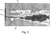
- the fluidic oscillator then mixes the first atomized fluid and the second atomized fluid by alternating outputting the atomized first fluid 21 and the atomized second fluid 22 as shown in Figure 3 .
- the fluidic oscillator further mixes the first atomized fluid and the second atomized fluid in the chamber 14 before alternating outputting.
- a geometry of the pressure inlet 13, the first fluid inlet 11, the second fluid inlet 12, the first outlet 15 and/or the second outlet 16 may be variable to control a frequency of outputting the atomized first fluid 21 and/or a frequency of outputting the atomized second fluid 22. Also a geometry of the pressure inlet 13, the first fluid inlet 11 and/or the second fluid inlet 12 may be variable to control the atomization.
- Figure 4 shows schematically and exemplarily a method for atomizing a fluid which is not part of the invention as claimed.
Landscapes
- Nozzles (AREA)
Description
- The invention relates to a device for atomizing a fluid, a use of such device for e.g. injection of combustible, spraying, fire extinction, cooling, heating and heat exchange and a method for atomizing a fluid.
- In the prior art, device for atomizing a fluid are known which comprise moving components. These device can, however, be greatly improved. See for example
US3748852 . - Hence, there may be a need to provide an improved device for atomizing a fluid, which is in particular easy to manufacture.
- The problem of the present invention is solved by the subject-matters of the independent claim, wherein further embodiments are incorporated in the dependent claims. It should be noted that the aspects of the invention described in the following apply to the device for atomizing a fluid and the use of such device.
- According to the present invention, a device for atomizing a fluid is presented.
- Thereby, the present invention provides a device for atomizing a fluid, wherein the design and/or mechanical structure of the device is simple and therefore easy and cheap to manufacture, to maintain, to repair and to use.
- The device can be designed without moving parts, which further increases the benefits in view of manufacturing and handling. In other words, the device is a passive fluidic device which is only driven by the provided pressurized gas. The first and second fluids can be automatically sucked in the chamber from preferably unpressurized container(s) by means of the pressurized gas provided by the pressure inlet. The first and second fluids are then automatically atomized in the chamber, again by means of the pressurized gas. The pressurized gas might be e.g. air with 1 bar excess pressure, different water solutions at the like.
- Then, the first and second fluids can be outputted or released alternating or alternatively through the first outlet and the second outlet by means of the construction of the chamber as fluidic oscillator. In such fluidic oscillator, oscillations are produced purely by fluid-dynamic instabilities within the chamber.
- The fluidic oscillator might be a bi-stable fluidic oscillator which is a device designed and formed to alternating attach the pressurized gas to a chamber wall next to the first fluid inlet or to the second fluid inlet, so that the pressurized gas alternating draws the first fluid and the second fluid into the chamber and outputs the atomized first fluid and the atomized second fluid alternating or alternatively through the first outlet and the second outlet.
- As a result, the released atomized first fluid and the atomized second fluid are pulsed from the first and the second outlets or orifices. The first and the second outlets can be alternating at high and variable frequency of e.g. up to 250 Hz. The first and the second outlets can be alternating to produce coherent turbulent structures, such that e.g. heat can be carried away efficiently.
- The device according to the invention can be designed to be very compact and small, even quasi 2D is possible, and can therefore be designed to be incorporated in a small installation space. The device for atomizing a fluid can also be easily scaled in a wide range for applications with different requirements of e.g. installation space, output pressure, output volume, output speed and the like. For example, sizes from 30 cm to less than 1 cm are possible.
- The device for atomizing a fluid according to the invention allows using either gas or liquid and allows a generation of very fine particles e.g. in the range of 100 nm to 0.5 mm. Further, a good degree of mixing can be achieved without mixing the fluids in advance.
- In an example, the fluidic oscillator is configured to mix the first atomized fluid and the second atomized fluid by alternating outputting the atomized first fluid and the atomized second fluid. In an example, the fluidic oscillator is configured to mix the first atomized fluid and the second atomized fluid in the chamber before alternating outputting. In an example, the mixing of the first atomized fluid and the second atomized fluid is based on turbulences in the first atomized fluid and the second atomized fluid. In an example, the first outlet and the second outlet are configured to further atomize the first fluid and the second fluid.
- The device for atomizing a fluid according to the invention can be used for injection and fine distribution of combustible for efficient burning, for spraying one- or two-component paint or varnish, for spraying with a catalytic component for e.g. large surfaces, for fire extinction in e.g. cargo and/or cabin compartments of an aircraft or vehicle with one- or two-component fire extinguisher, for cooling and temperature reduction of e.g. exhaust plume, hot spots and/or surfaces, for heat exchange and the like.
- In an example, a geometry of at least one of a group of the pressure inlet, the first fluid inlet, the second fluid inlet, the first outlet and the second outlet is variable to control a frequency of outputting the atomized first fluid and/or a frequency of outputting the atomized second fluid. In an example, a geometry of at least one of the group of the pressure inlet, the first fluid inlet and the second fluid inlet is variable to control the atomization.
- Of course, the device according to the invention may comprise more than two fluid inlets, e.g. a third fluid inlet leading into the chamber. The fluidic oscillator might then be a tri-stable fluidic oscillator configured to alternating attach the pressurized gas to the first, second or to third fluid inlet so that the pressurized gas alternating draws the first, second or to third fluids into the chamber, atomizes the first, second or to third fluids and outputs the atomized first, second or to third fluid alternating through the first outlet and the second outlet. Here, also a third outlet can be provided to output the first, second or to third fluids through the first, second or to third outlets.
- In an example, the first outlet and/or the second outlet are a nozzle designed based on the application field of the device according to the invention.
- The components of the device according to the invention can be made from metals, polymers and/or many other materials, according to temperature requirements.
- According to the present invention, also a use of a device as described above is presented for injection of combustible, spraying, fire extinction, cooling, heating, heat exchange and/or the like.
- These and other aspects of the present invention will become apparent from and be elucidated with reference to the embodiments described hereinafter.
- Exemplary embodiments of the invention will be described in the following with reference to the accompanying drawing:
- Figure 1
- shows schematically and exemplarily an isometric view of a device for atomizing a fluid.
- Figure 2
- shows schematically and exemplarily a plan view of the device shown in
Figure 1 . - Figure 3
- shows schematically and exemplarily an alternating outputting of an atomized first fluid and an atomized second fluid.
- Figure 4
- shows schematically and exemplarily a method for atomizing a fluid which is not part of the invention as claimed.
-
Figure 1 shows schematically and exemplarily an isometric view of adevice 10 for atomizing a fluid. Thedevice 10 for atomizing a fluid comprises a top part 1, abottom part 2, a pressure inlet 13 for providing a pressurizedgas 23, a first fluid inlet 11 for providing afirst fluid 21, a second fluid inlet 12 for providing asecond fluid 22, achamber 14, afirst outlet 15, and asecond outlet 16.Figure 2 shows schematically and exemplarily a plan view of thebottom part 2 of thedevice 10 shown inFigure 1 . Thepressure inlet 13, the first fluid inlet 11 and thesecond fluid inlet 12 lead into thechamber 14 and thefirst outlet 15 and thesecond outlet 16 leave thechamber 14. - The
pressure inlet 13, thefirst fluid inlet 11 and thesecond fluid inlet 12 are designed such that the pressurizedgas 23 provided by thepressure inlet 13 draws thefirst fluid 21 and thesecond fluid 22 into thechamber 14. Thechamber 14 is part of a fluidic oscillator to alternating attach the pressurizedgas 23 to thefirst fluid inlet 11 or to the second fluid inlet 12, so that the pressurizedgas 23 alternating draws thefirst fluid 21 and thesecond fluid 22 into thechamber 14, atomizes thefirst fluid 21 and thesecond fluid 22 and outputs the atomizedfirst fluid 21 and the atomizedsecond fluid 22 alternating through thefirst outlet 15 and thesecond outlet 16. - The
first fluid 21 might be a gas or a liquid. Thesecond fluid 22 might also be a gas or a liquid. Thefirst outlet 15 and thesecond outlet 16 are here nozzles designed based on the particular application field of thedevice 10. - The
device 10 is designed without any moving parts, which means thedevice 10 is a passivefluidic device 10 which is only driven by the pressurizedgas 23 provided by thepressure inlet 13. The first and second fluids are first automatically sucked from unpressurized containers into thechamber 14 and then therein automatically atomized by means of the pressurizedgas 23. The pressurizedgas 23 is e.g. air with about 1 bar excess pressure. - The
chamber 14 and the fluidic connections around form a bi-stable fluidic oscillator designed to alternating attach thepressurized gas 23 to achamber 14 wall next to thefirst fluid inlet 11 or to achamber 14 wall next to thesecond fluid inlet 12, so that thepressurized gas 23 alternating draws thefirst fluid 21 and thesecond fluid 22 into thechamber 14 and outputs the atomized first fluid 21 and the atomized second fluid 22 alternating through thefirst outlet 15 and thesecond outlet 16. As a result, the released atomized first fluid 21 and the atomized second fluid 22 are pulsed from the first and thesecond outlets 16 or orifices. - The first and the
second fluid 22 are here different. The fluidic oscillator then mixes the first atomized fluid and the second atomized fluid by alternating outputting the atomized first fluid 21 and the atomized second fluid 22 as shown inFigure 3 . - Additionally and at first, the fluidic oscillator further mixes the first atomized fluid and the second atomized fluid in the
chamber 14 before alternating outputting. - A geometry of the
pressure inlet 13, thefirst fluid inlet 11, thesecond fluid inlet 12, thefirst outlet 15 and/or thesecond outlet 16 may be variable to control a frequency of outputting the atomized first fluid 21 and/or a frequency of outputting the atomizedsecond fluid 22. Also a geometry of thepressure inlet 13, thefirst fluid inlet 11 and/or thesecond fluid inlet 12 may be variable to control the atomization. -
Figure 4 shows schematically and exemplarily a method for atomizing a fluid which is not part of the invention as claimed. - While the invention has been illustrated and described in detail in the drawings and foregoing description, such illustration and description are to be considered illustrative or exemplary and not restrictive. The invention is not limited to the disclosed embodiments. Other variations to the disclosed embodiments can be understood and effected by those skilled in the art in practicing a claimed invention, from a study of the drawings, the disclosure, and the dependent claims.
- In the claims, the word "comprising" does not exclude other elements or steps, and the indefinite article "a" or "an" does not exclude a plurality. A single processor or other unit may fulfil the functions of several items re-cited in the claims. The mere fact that certain measures are re-cited in mutually different dependent claims does not indicate that a combination of these measures cannot be used to advantage. Any reference signs in the claims should not be construed as limiting the scope.
Claims (10)
- Device (10) for atomizing a fluid, comprising:- a pressure inlet (13) for providing a pressurized gas (23),- a first fluid inlet (11) for providing a first fluid (21),- a second fluid inlet (12) for providing a second fluid (22),- a chamber (14),- a first outlet (15), and- a second outlet (16),wherein the pressure inlet (13), the first fluid inlet (11) and the second fluid inlet (12) lead into the chamber (14) and the first outlet (15) and the second outlet (16) leave the chamber (14),
wherein the pressure inlet (13), the first fluid inlet (11) and the second fluid inlet (12) are configured such that the pressurized gas (23) provided by the pressure inlet (13) draws the first fluid and the second fluid (22) into the chamber (14),
wherein the chamber (14) is part of a fluidic oscillator configured to alternating attach the pressurized gas (23) to the first fluid inlet (11) or to the second fluid inlet (12), so that the pressurized gas (23) alternating draws the first fluid and the second fluid (22) into the chamber (14), atomizes the first fluid (21) and the second fluid (22) and outputs the atomized first fluid (21) and the atomized second fluid (22) alternating through the first outlet (15) and the second outlet (16),
characterized in that a geometry of at least one of a group of the pressure inlet (13), the first fluid inlet (11), the second fluid inlet (12) is variable to control the atomization and/or a frequency of outputting the atomized first fluid (21) and/or a frequency of outputting the atomized second fluid (22). - The device (10) according to claim 1, wherein the fluidic oscillator is configured to mix the first atomized fluid and the second atomized fluid in the chamber (14).
- The device (10) according to one of the preceding claims, wherein the first outlet (15) and the second outlet (16) are configured to further atomize the first fluid (21) and the second fluid (22).
- The device (10) according to one of the preceding claims, further comprising an unpressurized container for the first fluid (21) and the second fluid (22).
- The device (10) according to one of the preceding claims, wherein a geometry of at least one of a group of the first outlet (15) and the second outlet (16) is variable to control a frequency of outputting the atomized first fluid (21) and/or a frequency of outputting the atomized second fluid (22).
- Use of a device (10) according to one of the preceding claims for one of a group of injection of combustible, spraying, fire extinction, cooling, heating and heat exchange.
- Use according to claim 6, wherein the first fluid (21) is the same as the second fluid (22).
- Use according to claim 6, wherein the second fluid (22) is different to the first fluid (21), and wherein the fluidic oscillator is configured to mix the first atomized fluid and the second atomized fluid by alternating outputting the atomized first fluid (21) and the atomized second fluid (22).
- Use according to claim 8, wherein the mixing of the first atomized fluid and the second atomized fluid is based on turbulences in the first atomized fluid and the second atomized fluid.
- Use according to one of the preceding claims 6-9, wherein the device (10) is only driven by the provided pressurized gas (23).
Applications Claiming Priority (1)
| Application Number | Priority Date | Filing Date | Title |
|---|---|---|---|
| PCT/EP2015/079299 WO2017097365A1 (en) | 2015-12-10 | 2015-12-10 | Device for atomizing a fluid |
Publications (2)
| Publication Number | Publication Date |
|---|---|
| EP3386641A1 EP3386641A1 (en) | 2018-10-17 |
| EP3386641B1 true EP3386641B1 (en) | 2020-07-01 |
Family
ID=54849619
Family Applications (1)
| Application Number | Title | Priority Date | Filing Date |
|---|---|---|---|
| EP15808387.3A Active EP3386641B1 (en) | 2015-12-10 | 2015-12-10 | Device for atomizing a fluid |
Country Status (2)
| Country | Link |
|---|---|
| EP (1) | EP3386641B1 (en) |
| WO (1) | WO2017097365A1 (en) |
Family Cites Families (4)
| Publication number | Priority date | Publication date | Assignee | Title |
|---|---|---|---|---|
| US3388862A (en) * | 1965-12-01 | 1968-06-18 | Exxon Research Engineering Co | Pneumatic control of furnaces |
| US3748852A (en) * | 1969-12-05 | 1973-07-31 | L Cole | Self-stabilizing pressure compensated injector |
| DE4439437A1 (en) * | 1994-11-04 | 1996-05-09 | Stihl Maschf Andreas | High pressure nozzle for high pressure cleaning equipment |
| US6581856B1 (en) * | 1998-11-06 | 2003-06-24 | Bowles Fluidics Corporation | Fluid mixer |
-
2015
- 2015-12-10 WO PCT/EP2015/079299 patent/WO2017097365A1/en not_active Ceased
- 2015-12-10 EP EP15808387.3A patent/EP3386641B1/en active Active
Non-Patent Citations (1)
| Title |
|---|
| None * |
Also Published As
| Publication number | Publication date |
|---|---|
| EP3386641A1 (en) | 2018-10-17 |
| WO2017097365A1 (en) | 2017-06-15 |
Similar Documents
| Publication | Publication Date | Title |
|---|---|---|
| EP1813352B1 (en) | Device for the pneumatic atomisation of liquids using an implosive gas stream | |
| RU2137039C1 (en) | Liquid injector | |
| RU2461427C1 (en) | Kochetov's fluid spray nozzle | |
| RU2416445C1 (en) | Fluid sprayer | |
| RU2469758C1 (en) | Kochetov liquid-fuel atomiser | |
| EP1718413A1 (en) | Method and apparatus for generating a mist | |
| MX2007015843A (en) | High velocity low pressure emitter. | |
| RU2501586C1 (en) | Nozzle with swirler of double twist of flow | |
| JPS61138559A (en) | Oscillator for ultrasonic wave injection nozzle | |
| RU2416442C1 (en) | Kochetov's sprayer | |
| JPS61259782A (en) | Vibrator for ultrasonic atomization having multistage edge part | |
| US10286240B2 (en) | Automatic nozzle for firefighting systems | |
| KR101732643B1 (en) | A Nozzle Assembly for Atomizing Liquid | |
| RU2473396C1 (en) | Kochetov's pneumatic sprayer | |
| Mahrukh et al. | Effects of angular injection, and effervescent atomization on high-velocity suspension flame spray process | |
| JP2015078775A5 (en) | ||
| EP3204169B1 (en) | Liquid atomization method and device | |
| EP3386641A1 (en) | Device for atomizing a fluid | |
| CN203030456U (en) | Atomizing nozzle device | |
| Khatami et al. | Modeling of aerosol spray characteristics for synthesis of sensor thin film from solution | |
| TWI270412B (en) | Integrated micro-mixing atomization system | |
| RU2553954C1 (en) | Kochetov's atomiser | |
| Naz et al. | Spatio-temporal droplet size statistics in developing spray of starchy solution | |
| TWI587925B (en) | Spray granulation nozzle device with aided multiple excitation and electrostatic | |
| Mlkvik et al. | Comparison of Y-jet and OIL effervescent atomizers based on internal and external two-phase flow characteristics |
Legal Events
| Date | Code | Title | Description |
|---|---|---|---|
| STAA | Information on the status of an ep patent application or granted ep patent |
Free format text: STATUS: THE INTERNATIONAL PUBLICATION HAS BEEN MADE |
|
| PUAI | Public reference made under article 153(3) epc to a published international application that has entered the european phase |
Free format text: ORIGINAL CODE: 0009012 |
|
| STAA | Information on the status of an ep patent application or granted ep patent |
Free format text: STATUS: REQUEST FOR EXAMINATION WAS MADE |
|
| 17P | Request for examination filed |
Effective date: 20180418 |
|
| AK | Designated contracting states |
Kind code of ref document: A1 Designated state(s): AL AT BE BG CH CY CZ DE DK EE ES FI FR GB GR HR HU IE IS IT LI LT LU LV MC MK MT NL NO PL PT RO RS SE SI SK SM TR |
|
| AX | Request for extension of the european patent |
Extension state: BA ME |
|
| DAV | Request for validation of the european patent (deleted) | ||
| DAX | Request for extension of the european patent (deleted) | ||
| GRAP | Despatch of communication of intention to grant a patent |
Free format text: ORIGINAL CODE: EPIDOSNIGR1 |
|
| STAA | Information on the status of an ep patent application or granted ep patent |
Free format text: STATUS: GRANT OF PATENT IS INTENDED |
|
| INTG | Intention to grant announced |
Effective date: 20200120 |
|
| GRAS | Grant fee paid |
Free format text: ORIGINAL CODE: EPIDOSNIGR3 |
|
| GRAA | (expected) grant |
Free format text: ORIGINAL CODE: 0009210 |
|
| STAA | Information on the status of an ep patent application or granted ep patent |
Free format text: STATUS: THE PATENT HAS BEEN GRANTED |
|
| AK | Designated contracting states |
Kind code of ref document: B1 Designated state(s): AL AT BE BG CH CY CZ DE DK EE ES FI FR GB GR HR HU IE IS IT LI LT LU LV MC MK MT NL NO PL PT RO RS SE SI SK SM TR |
|
| REG | Reference to a national code |
Ref country code: AT Ref legal event code: REF Ref document number: 1285656 Country of ref document: AT Kind code of ref document: T Effective date: 20200715 Ref country code: CH Ref legal event code: EP |
|
| REG | Reference to a national code |
Ref country code: IE Ref legal event code: FG4D |
|
| REG | Reference to a national code |
Ref country code: DE Ref legal event code: R096 Ref document number: 602015055162 Country of ref document: DE |
|
| REG | Reference to a national code |
Ref country code: LT Ref legal event code: MG4D |
|
| PG25 | Lapsed in a contracting state [announced via postgrant information from national office to epo] |
Ref country code: BG Free format text: LAPSE BECAUSE OF FAILURE TO SUBMIT A TRANSLATION OF THE DESCRIPTION OR TO PAY THE FEE WITHIN THE PRESCRIBED TIME-LIMIT Effective date: 20201001 |
|
| REG | Reference to a national code |
Ref country code: NL Ref legal event code: MP Effective date: 20200701 |
|
| REG | Reference to a national code |
Ref country code: AT Ref legal event code: MK05 Ref document number: 1285656 Country of ref document: AT Kind code of ref document: T Effective date: 20200701 |
|
| PG25 | Lapsed in a contracting state [announced via postgrant information from national office to epo] |
Ref country code: GR Free format text: LAPSE BECAUSE OF FAILURE TO SUBMIT A TRANSLATION OF THE DESCRIPTION OR TO PAY THE FEE WITHIN THE PRESCRIBED TIME-LIMIT Effective date: 20201002 Ref country code: FI Free format text: LAPSE BECAUSE OF FAILURE TO SUBMIT A TRANSLATION OF THE DESCRIPTION OR TO PAY THE FEE WITHIN THE PRESCRIBED TIME-LIMIT Effective date: 20200701 Ref country code: CZ Free format text: LAPSE BECAUSE OF FAILURE TO SUBMIT A TRANSLATION OF THE DESCRIPTION OR TO PAY THE FEE WITHIN THE PRESCRIBED TIME-LIMIT Effective date: 20200701 Ref country code: ES Free format text: LAPSE BECAUSE OF FAILURE TO SUBMIT A TRANSLATION OF THE DESCRIPTION OR TO PAY THE FEE WITHIN THE PRESCRIBED TIME-LIMIT Effective date: 20200701 Ref country code: HR Free format text: LAPSE BECAUSE OF FAILURE TO SUBMIT A TRANSLATION OF THE DESCRIPTION OR TO PAY THE FEE WITHIN THE PRESCRIBED TIME-LIMIT Effective date: 20200701 Ref country code: LT Free format text: LAPSE BECAUSE OF FAILURE TO SUBMIT A TRANSLATION OF THE DESCRIPTION OR TO PAY THE FEE WITHIN THE PRESCRIBED TIME-LIMIT Effective date: 20200701 Ref country code: PT Free format text: LAPSE BECAUSE OF FAILURE TO SUBMIT A TRANSLATION OF THE DESCRIPTION OR TO PAY THE FEE WITHIN THE PRESCRIBED TIME-LIMIT Effective date: 20201102 Ref country code: AT Free format text: LAPSE BECAUSE OF FAILURE TO SUBMIT A TRANSLATION OF THE DESCRIPTION OR TO PAY THE FEE WITHIN THE PRESCRIBED TIME-LIMIT Effective date: 20200701 Ref country code: NO Free format text: LAPSE BECAUSE OF FAILURE TO SUBMIT A TRANSLATION OF THE DESCRIPTION OR TO PAY THE FEE WITHIN THE PRESCRIBED TIME-LIMIT Effective date: 20201001 Ref country code: SE Free format text: LAPSE BECAUSE OF FAILURE TO SUBMIT A TRANSLATION OF THE DESCRIPTION OR TO PAY THE FEE WITHIN THE PRESCRIBED TIME-LIMIT Effective date: 20200701 |
|
| PG25 | Lapsed in a contracting state [announced via postgrant information from national office to epo] |
Ref country code: IS Free format text: LAPSE BECAUSE OF FAILURE TO SUBMIT A TRANSLATION OF THE DESCRIPTION OR TO PAY THE FEE WITHIN THE PRESCRIBED TIME-LIMIT Effective date: 20201101 Ref country code: PL Free format text: LAPSE BECAUSE OF FAILURE TO SUBMIT A TRANSLATION OF THE DESCRIPTION OR TO PAY THE FEE WITHIN THE PRESCRIBED TIME-LIMIT Effective date: 20200701 Ref country code: RS Free format text: LAPSE BECAUSE OF FAILURE TO SUBMIT A TRANSLATION OF THE DESCRIPTION OR TO PAY THE FEE WITHIN THE PRESCRIBED TIME-LIMIT Effective date: 20200701 Ref country code: LV Free format text: LAPSE BECAUSE OF FAILURE TO SUBMIT A TRANSLATION OF THE DESCRIPTION OR TO PAY THE FEE WITHIN THE PRESCRIBED TIME-LIMIT Effective date: 20200701 |
|
| PG25 | Lapsed in a contracting state [announced via postgrant information from national office to epo] |
Ref country code: NL Free format text: LAPSE BECAUSE OF FAILURE TO SUBMIT A TRANSLATION OF THE DESCRIPTION OR TO PAY THE FEE WITHIN THE PRESCRIBED TIME-LIMIT Effective date: 20200701 |
|
| REG | Reference to a national code |
Ref country code: DE Ref legal event code: R097 Ref document number: 602015055162 Country of ref document: DE |
|
| PG25 | Lapsed in a contracting state [announced via postgrant information from national office to epo] |
Ref country code: SM Free format text: LAPSE BECAUSE OF FAILURE TO SUBMIT A TRANSLATION OF THE DESCRIPTION OR TO PAY THE FEE WITHIN THE PRESCRIBED TIME-LIMIT Effective date: 20200701 Ref country code: RO Free format text: LAPSE BECAUSE OF FAILURE TO SUBMIT A TRANSLATION OF THE DESCRIPTION OR TO PAY THE FEE WITHIN THE PRESCRIBED TIME-LIMIT Effective date: 20200701 Ref country code: EE Free format text: LAPSE BECAUSE OF FAILURE TO SUBMIT A TRANSLATION OF THE DESCRIPTION OR TO PAY THE FEE WITHIN THE PRESCRIBED TIME-LIMIT Effective date: 20200701 Ref country code: IT Free format text: LAPSE BECAUSE OF FAILURE TO SUBMIT A TRANSLATION OF THE DESCRIPTION OR TO PAY THE FEE WITHIN THE PRESCRIBED TIME-LIMIT Effective date: 20200701 Ref country code: DK Free format text: LAPSE BECAUSE OF FAILURE TO SUBMIT A TRANSLATION OF THE DESCRIPTION OR TO PAY THE FEE WITHIN THE PRESCRIBED TIME-LIMIT Effective date: 20200701 |
|
| PLBE | No opposition filed within time limit |
Free format text: ORIGINAL CODE: 0009261 |
|
| STAA | Information on the status of an ep patent application or granted ep patent |
Free format text: STATUS: NO OPPOSITION FILED WITHIN TIME LIMIT |
|
| PG25 | Lapsed in a contracting state [announced via postgrant information from national office to epo] |
Ref country code: AL Free format text: LAPSE BECAUSE OF FAILURE TO SUBMIT A TRANSLATION OF THE DESCRIPTION OR TO PAY THE FEE WITHIN THE PRESCRIBED TIME-LIMIT Effective date: 20200701 |
|
| 26N | No opposition filed |
Effective date: 20210406 |
|
| PG25 | Lapsed in a contracting state [announced via postgrant information from national office to epo] |
Ref country code: SK Free format text: LAPSE BECAUSE OF FAILURE TO SUBMIT A TRANSLATION OF THE DESCRIPTION OR TO PAY THE FEE WITHIN THE PRESCRIBED TIME-LIMIT Effective date: 20200701 |
|
| REG | Reference to a national code |
Ref country code: CH Ref legal event code: PL |
|
| PG25 | Lapsed in a contracting state [announced via postgrant information from national office to epo] |
Ref country code: MC Free format text: LAPSE BECAUSE OF FAILURE TO SUBMIT A TRANSLATION OF THE DESCRIPTION OR TO PAY THE FEE WITHIN THE PRESCRIBED TIME-LIMIT Effective date: 20200701 Ref country code: SI Free format text: LAPSE BECAUSE OF FAILURE TO SUBMIT A TRANSLATION OF THE DESCRIPTION OR TO PAY THE FEE WITHIN THE PRESCRIBED TIME-LIMIT Effective date: 20200701 |
|
| REG | Reference to a national code |
Ref country code: BE Ref legal event code: MM Effective date: 20201231 |
|
| PG25 | Lapsed in a contracting state [announced via postgrant information from national office to epo] |
Ref country code: LU Free format text: LAPSE BECAUSE OF NON-PAYMENT OF DUE FEES Effective date: 20201210 Ref country code: IE Free format text: LAPSE BECAUSE OF NON-PAYMENT OF DUE FEES Effective date: 20201210 |
|
| PG25 | Lapsed in a contracting state [announced via postgrant information from national office to epo] |
Ref country code: LI Free format text: LAPSE BECAUSE OF NON-PAYMENT OF DUE FEES Effective date: 20201231 Ref country code: CH Free format text: LAPSE BECAUSE OF NON-PAYMENT OF DUE FEES Effective date: 20201231 |
|
| PG25 | Lapsed in a contracting state [announced via postgrant information from national office to epo] |
Ref country code: TR Free format text: LAPSE BECAUSE OF FAILURE TO SUBMIT A TRANSLATION OF THE DESCRIPTION OR TO PAY THE FEE WITHIN THE PRESCRIBED TIME-LIMIT Effective date: 20200701 Ref country code: MT Free format text: LAPSE BECAUSE OF FAILURE TO SUBMIT A TRANSLATION OF THE DESCRIPTION OR TO PAY THE FEE WITHIN THE PRESCRIBED TIME-LIMIT Effective date: 20200701 Ref country code: CY Free format text: LAPSE BECAUSE OF FAILURE TO SUBMIT A TRANSLATION OF THE DESCRIPTION OR TO PAY THE FEE WITHIN THE PRESCRIBED TIME-LIMIT Effective date: 20200701 |
|
| PG25 | Lapsed in a contracting state [announced via postgrant information from national office to epo] |
Ref country code: MK Free format text: LAPSE BECAUSE OF FAILURE TO SUBMIT A TRANSLATION OF THE DESCRIPTION OR TO PAY THE FEE WITHIN THE PRESCRIBED TIME-LIMIT Effective date: 20200701 |
|
| PG25 | Lapsed in a contracting state [announced via postgrant information from national office to epo] |
Ref country code: BE Free format text: LAPSE BECAUSE OF NON-PAYMENT OF DUE FEES Effective date: 20201231 |
|
| PGFP | Annual fee paid to national office [announced via postgrant information from national office to epo] |
Ref country code: DE Payment date: 20251211 Year of fee payment: 11 |
|
| PGFP | Annual fee paid to national office [announced via postgrant information from national office to epo] |
Ref country code: GB Payment date: 20251219 Year of fee payment: 11 |
|
| PGFP | Annual fee paid to national office [announced via postgrant information from national office to epo] |
Ref country code: FR Payment date: 20251229 Year of fee payment: 11 |