EP3386417B1 - Pulley arrangement for articulating a surgical instrument - Google Patents
Pulley arrangement for articulating a surgical instrument Download PDFInfo
- Publication number
- EP3386417B1 EP3386417B1 EP16812808.0A EP16812808A EP3386417B1 EP 3386417 B1 EP3386417 B1 EP 3386417B1 EP 16812808 A EP16812808 A EP 16812808A EP 3386417 B1 EP3386417 B1 EP 3386417B1
- Authority
- EP
- European Patent Office
- Prior art keywords
- pulley
- pulleys
- shaft
- driving elements
- pair
- Prior art date
- Legal status (The legal status is an assumption and is not a legal conclusion. Google has not performed a legal analysis and makes no representation as to the accuracy of the status listed.)
- Active
Links
Images


Classifications
-
- A—HUMAN NECESSITIES
- A61—MEDICAL OR VETERINARY SCIENCE; HYGIENE
- A61B—DIAGNOSIS; SURGERY; IDENTIFICATION
- A61B17/00—Surgical instruments, devices or methods
- A61B17/00234—Surgical instruments, devices or methods for minimally invasive surgery
-
- A—HUMAN NECESSITIES
- A61—MEDICAL OR VETERINARY SCIENCE; HYGIENE
- A61B—DIAGNOSIS; SURGERY; IDENTIFICATION
- A61B17/00—Surgical instruments, devices or methods
- A61B17/28—Surgical forceps
- A61B17/29—Forceps for use in minimally invasive surgery
- A61B17/2909—Handles
-
- A—HUMAN NECESSITIES
- A61—MEDICAL OR VETERINARY SCIENCE; HYGIENE
- A61B—DIAGNOSIS; SURGERY; IDENTIFICATION
- A61B34/00—Computer-aided surgery; Manipulators or robots specially adapted for use in surgery
- A61B34/30—Surgical robots
-
- A—HUMAN NECESSITIES
- A61—MEDICAL OR VETERINARY SCIENCE; HYGIENE
- A61B—DIAGNOSIS; SURGERY; IDENTIFICATION
- A61B34/00—Computer-aided surgery; Manipulators or robots specially adapted for use in surgery
- A61B34/70—Manipulators specially adapted for use in surgery
-
- A—HUMAN NECESSITIES
- A61—MEDICAL OR VETERINARY SCIENCE; HYGIENE
- A61B—DIAGNOSIS; SURGERY; IDENTIFICATION
- A61B34/00—Computer-aided surgery; Manipulators or robots specially adapted for use in surgery
- A61B34/70—Manipulators specially adapted for use in surgery
- A61B34/71—Manipulators operated by drive cable mechanisms
-
- B—PERFORMING OPERATIONS; TRANSPORTING
- B25—HAND TOOLS; PORTABLE POWER-DRIVEN TOOLS; MANIPULATORS
- B25J—MANIPULATORS; CHAMBERS PROVIDED WITH MANIPULATION DEVICES
- B25J17/00—Joints
-
- B—PERFORMING OPERATIONS; TRANSPORTING
- B25—HAND TOOLS; PORTABLE POWER-DRIVEN TOOLS; MANIPULATORS
- B25J—MANIPULATORS; CHAMBERS PROVIDED WITH MANIPULATION DEVICES
- B25J17/00—Joints
- B25J17/02—Wrist joints
-
- B—PERFORMING OPERATIONS; TRANSPORTING
- B25—HAND TOOLS; PORTABLE POWER-DRIVEN TOOLS; MANIPULATORS
- B25J—MANIPULATORS; CHAMBERS PROVIDED WITH MANIPULATION DEVICES
- B25J9/00—Programme-controlled manipulators
- B25J9/10—Programme-controlled manipulators characterised by positioning means for manipulator elements
- B25J9/104—Programme-controlled manipulators characterised by positioning means for manipulator elements with cables, chains or ribbons
- B25J9/1045—Programme-controlled manipulators characterised by positioning means for manipulator elements with cables, chains or ribbons comprising tensioning means
-
- A—HUMAN NECESSITIES
- A61—MEDICAL OR VETERINARY SCIENCE; HYGIENE
- A61B—DIAGNOSIS; SURGERY; IDENTIFICATION
- A61B17/00—Surgical instruments, devices or methods
- A61B17/00234—Surgical instruments, devices or methods for minimally invasive surgery
- A61B2017/00292—Surgical instruments, devices or methods for minimally invasive surgery mounted on or guided by flexible, e.g. catheter-like, means
- A61B2017/003—Steerable
- A61B2017/00305—Constructional details of the flexible means
- A61B2017/00314—Separate linked members
-
- A—HUMAN NECESSITIES
- A61—MEDICAL OR VETERINARY SCIENCE; HYGIENE
- A61B—DIAGNOSIS; SURGERY; IDENTIFICATION
- A61B17/00—Surgical instruments, devices or methods
- A61B17/00234—Surgical instruments, devices or methods for minimally invasive surgery
- A61B2017/00292—Surgical instruments, devices or methods for minimally invasive surgery mounted on or guided by flexible, e.g. catheter-like, means
- A61B2017/003—Steerable
- A61B2017/00318—Steering mechanisms
- A61B2017/00323—Cables or rods
- A61B2017/00327—Cables or rods with actuating members moving in opposite directions
-
- A—HUMAN NECESSITIES
- A61—MEDICAL OR VETERINARY SCIENCE; HYGIENE
- A61B—DIAGNOSIS; SURGERY; IDENTIFICATION
- A61B17/00—Surgical instruments, devices or methods
- A61B2017/00477—Coupling
-
- A—HUMAN NECESSITIES
- A61—MEDICAL OR VETERINARY SCIENCE; HYGIENE
- A61B—DIAGNOSIS; SURGERY; IDENTIFICATION
- A61B17/00—Surgical instruments, devices or methods
- A61B17/28—Surgical forceps
- A61B17/29—Forceps for use in minimally invasive surgery
- A61B2017/2901—Details of shaft
- A61B2017/2902—Details of shaft characterized by features of the actuating rod
- A61B2017/2903—Details of shaft characterized by features of the actuating rod transferring rotary motion
-
- A—HUMAN NECESSITIES
- A61—MEDICAL OR VETERINARY SCIENCE; HYGIENE
- A61B—DIAGNOSIS; SURGERY; IDENTIFICATION
- A61B17/00—Surgical instruments, devices or methods
- A61B17/28—Surgical forceps
- A61B17/29—Forceps for use in minimally invasive surgery
- A61B2017/2901—Details of shaft
- A61B2017/2908—Multiple segments connected by articulations
-
- A—HUMAN NECESSITIES
- A61—MEDICAL OR VETERINARY SCIENCE; HYGIENE
- A61B—DIAGNOSIS; SURGERY; IDENTIFICATION
- A61B17/00—Surgical instruments, devices or methods
- A61B17/28—Surgical forceps
- A61B17/29—Forceps for use in minimally invasive surgery
- A61B17/2909—Handles
- A61B2017/2912—Handles transmission of forces to actuating rod or piston
- A61B2017/2919—Handles transmission of forces to actuating rod or piston details of linkages or pivot points
- A61B2017/292—Handles transmission of forces to actuating rod or piston details of linkages or pivot points connection of actuating rod to handle, e.g. ball end in recess
-
- A—HUMAN NECESSITIES
- A61—MEDICAL OR VETERINARY SCIENCE; HYGIENE
- A61B—DIAGNOSIS; SURGERY; IDENTIFICATION
- A61B17/00—Surgical instruments, devices or methods
- A61B17/28—Surgical forceps
- A61B17/29—Forceps for use in minimally invasive surgery
- A61B2017/2926—Details of heads or jaws
- A61B2017/2927—Details of heads or jaws the angular position of the head being adjustable with respect to the shaft
- A61B2017/2929—Details of heads or jaws the angular position of the head being adjustable with respect to the shaft with a head rotatable about the longitudinal axis of the shaft
-
- A—HUMAN NECESSITIES
- A61—MEDICAL OR VETERINARY SCIENCE; HYGIENE
- A61B—DIAGNOSIS; SURGERY; IDENTIFICATION
- A61B17/00—Surgical instruments, devices or methods
- A61B17/28—Surgical forceps
- A61B17/29—Forceps for use in minimally invasive surgery
- A61B2017/2926—Details of heads or jaws
- A61B2017/2932—Transmission of forces to jaw members
- A61B2017/2938—Independently actuatable jaw members, e.g. two actuating rods
-
- A—HUMAN NECESSITIES
- A61—MEDICAL OR VETERINARY SCIENCE; HYGIENE
- A61B—DIAGNOSIS; SURGERY; IDENTIFICATION
- A61B17/00—Surgical instruments, devices or methods
- A61B17/28—Surgical forceps
- A61B17/29—Forceps for use in minimally invasive surgery
- A61B2017/2926—Details of heads or jaws
- A61B2017/2932—Transmission of forces to jaw members
- A61B2017/2944—Translation of jaw members
-
- A—HUMAN NECESSITIES
- A61—MEDICAL OR VETERINARY SCIENCE; HYGIENE
- A61B—DIAGNOSIS; SURGERY; IDENTIFICATION
- A61B17/00—Surgical instruments, devices or methods
- A61B17/28—Surgical forceps
- A61B17/29—Forceps for use in minimally invasive surgery
- A61B2017/2947—Pivots
-
- A—HUMAN NECESSITIES
- A61—MEDICAL OR VETERINARY SCIENCE; HYGIENE
- A61B—DIAGNOSIS; SURGERY; IDENTIFICATION
- A61B34/00—Computer-aided surgery; Manipulators or robots specially adapted for use in surgery
- A61B34/30—Surgical robots
- A61B2034/302—Surgical robots specifically adapted for manipulations within body cavities, e.g. within abdominal or thoracic cavities
-
- A—HUMAN NECESSITIES
- A61—MEDICAL OR VETERINARY SCIENCE; HYGIENE
- A61B—DIAGNOSIS; SURGERY; IDENTIFICATION
- A61B34/00—Computer-aided surgery; Manipulators or robots specially adapted for use in surgery
- A61B34/30—Surgical robots
- A61B2034/305—Details of wrist mechanisms at distal ends of robotic arms
- A61B2034/306—Wrists with multiple vertebrae
-
- A—HUMAN NECESSITIES
- A61—MEDICAL OR VETERINARY SCIENCE; HYGIENE
- A61B—DIAGNOSIS; SURGERY; IDENTIFICATION
- A61B34/00—Computer-aided surgery; Manipulators or robots specially adapted for use in surgery
- A61B34/70—Manipulators specially adapted for use in surgery
- A61B34/71—Manipulators operated by drive cable mechanisms
- A61B2034/715—Cable tensioning mechanisms for removing slack
Definitions
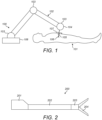
- Figure 1 illustrates a typical surgical robot 100 which consists of a base 108, an arm 102, and an instrument 105.
- the base supports the robot, and is itself attached rigidly to, for example, the operating theatre floor, the operating theatre ceiling or a trolley.
- the arm extends between the base and the instrument.
- the arm is articulated by means of multiple flexible joints 103 along its length, which are used to locate the surgical instrument in a desired location relative to the patient.
- the surgical instrument is attached to the distal end 104 of the robot arm.
- the surgical instrument penetrates the body of the patient 101 at a port 107 so as to access the surgical site.
- the instrument comprises an end effector 106 for engaging in a medical procedure.
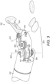
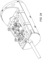
- FIG. 2 illustrates a typical surgical instrument 200 for performing robotic laparoscopic surgery.
- the surgical instrument comprises a base 201 by means of which the surgical instrument connects to the robot arm.
- a shaft 202 extends between base 201 and articulation 203.
- Articulation 203 terminates in an end effector 204.
- a pair of serrated jaws are illustrated as the end effector 204.
- the articulation 203 permits the end effector 204 to move relative to the shaft 202. It is desirable for at least two degrees of freedom to be provided to the motion of the end effector 204 by means of the articulation.
- Figure 3 illustrates an example of a known surgical instrument 300 in which end effector 204 is permitted to move relative to shaft 202 by means of pitch joint 301 and two yaw joints 302.
- Joint 301 enables the end effector 204 to rotate about pitch axis 303.
- Joints 302 enable each jaw of the end effector 204 to rotate about yaw axis 304.
- the joints are driven by cables 306, 307 and 308.
- Pulley 305 is used to direct cables 307 and 308 from their passage over the pitch joint to the yaw joints. Pulley 305 is offset from the central axis of the articulation 203.
- the external diameter of the shaft is 8mm in order to accommodate the number, size and location of the internal elements of the articulated portion.
- EP2783643 describes surgical instruments that may be manually operated to perform laparoscopic operations or various surgical operations.
- WO2014151952 describes a surgical tool including a tool shaft, and end effector and a wrist that couples the end effector to the tool shaft.
- the tool includes a drive mechanism configured to effect movement of one or both of the wrist and the end effector in yaw and pitch via independent actuation of four independent cable ends of two or more independent cables that extend between the drive mechanism and the wrist.
- US6394998 describes a surgical instrument removably mountable on a robotically controlled articulated arm.
- a wrist member is pivotally mounted on a working end of the shaft of the instrument and at least one end effector is pivotally mounted on the wrist member.
- a plurality of cables extend from the end effector element and the wrist member to cause selective angular displacement of the wrist member and end effector in response to selective pulling of the elongate elements.
- US6902560 describes a method of performing surgery in a body cavity by introducing an elongate shaft having a working end into the cavity.
- the elongate shaft has a working end and a wrist member pivotally coupled with the working end which can be rotated relative to the working end.
- the wrist member has a wrist axis.
- the method further includes rotating at least one of the elongate shaft around the shaft's axis and an end effector pivotally mounted on the wrist member around the wrist axis to position the end effector at a desired location inside the cavity.
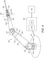
- Figure 4 illustrates a surgical robot having an arm 400 which extends from a base 401.
- the arm comprises a number of rigid limbs 402.
- the limbs are coupled by revolute joints 403.
- the most proximal limb 402a is coupled to the base by joint 403a. It and the other limbs are coupled in series by further ones of the joints 403.
- a wrist 404 is made up of four individual revolute joints.
- the wrist 404 couples one limb (402b) to the most distal limb (402c) of the arm.
- the most distal limb 402c carries an attachment 405 for a surgical instrument 406.
- Each joint 403 of the arm has one or more motors 407 which can be operated to cause rotational motion at the respective joint, and one or more position and/or torque sensors 408 which provide information regarding the current configuration and/or load at that joint.
- the motors are arranged proximally of the joints whose motion they drive, so as to improve weight distribution. For clarity, only some of the motors and sensors are shown in figure 4 .
- the arm may be generally as described in our co-pending patent application PCT/GB2014/053523 .
- the arm terminates in an attachment 405 for interfacing with the instrument 406.
- the instrument 406 takes the form described with respect to figure 2 .
- the instrument has a diameter less than 8mm.
- the instrument has a 5mm diameter.
- the instrument may have a diameter which is less than 5mm.
- the instrument diameter may be the diameter of the shaft.
- the instrument diameter may be the diameter of the profile of the articulation.
- the diameter of the profile of the articulation matches or is narrower than the diameter of the shaft.
- the attachment 405 comprises a drive assembly for driving articulation of the instrument.
- Movable interface elements of the drive assembly interface mechanically engage corresponding movable interface elements of the instrument interface in order to transfer drive from the robot arm to the instrument.
- One instrument is exchanged for another several times during a typical operation.
- the instrument is attachable and detachable from the robot arm during the operation.
- Features of the drive assembly interface and the instrument interface aid their alignment when brought into engagement with each other, so as to reduce the accuracy with which they need to be aligned by the user.
- the instrument 406 comprises an end effector for performing an operation.
- the end effector may take any suitable form.
- the end effector may be smooth jaws, serrated jaws, a gripper, a pair of shears, a needle for suturing, a camera, a laser, a knife, a stapler, a cauteriser, a suctioner.
- the instrument comprises an articulation between the instrument shaft and the end effector.
- the articulation comprises several joints which permit the end effector to move relative to the shaft of the instrument.
- the joints in the articulation are actuated by driving elements, such as cables. These driving elements are secured at the other end of the instrument shaft to the interface elements of the instrument interface.
- the robot arm transfers drive to the end effector as follows: movement of a drive assembly interface element moves an instrument interface element which moves a driving element which moves a joint of the articulation which moves the end effector.
- Controllers for the motors, torque sensors and encoders are distributed with the robot arm.
- the controllers are connected via a communication bus to control unit 409.
- a control unit 409 comprises a processor 410 and a memory 411.
- Memory 411 stores in a non-transient way software that is executable by the processor to control the operation of the motors 407 to cause the arm 400 to operate in the manner described herein.
- the software can control the processor 410 to cause the motors (for example via distributed controllers) to drive in dependence on inputs from the sensors 408 and from a surgeon command interface 412.
- the control unit 409 is coupled to the motors 407 for driving them in accordance with outputs generated by execution of the software.
- the control unit 409 is coupled to the sensors 408 for receiving sensed input from the sensors, and to the command interface 412 for receiving input from it.
- the respective couplings may, for example, each be electrical or optical cables, or may be provided by a wireless connection.
- the command interface 412 comprises one or more input devices whereby a user can request motion of the end effector in a desired way.
- the input devices could, for example, be manually operable mechanical input devices such as control handles or joysticks, or contactless input devices such as optical gesture sensors.
- the software stored in memory 411 is configured to respond to those inputs and cause the joints of the arm and instrument to move accordingly, in compliance with a pre-determined control strategy.
- the control strategy may include safety features which moderate the motion of the arm and instrument in response to command inputs.
- a surgeon at the command interface 412 can control the instrument 406 to move in such a way as to perform a desired surgical procedure.
- the control unit 409 and/or the command interface 412 may be remote from the arm 400.
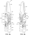
- Figures 5a and 5b illustrate opposing views of the distal end of a surgical instrument.
- the end effector 501 comprises a pair of end effector elements 502, 503, which in figures 5a and 5b are depicted as a pair of opposing serrated jaws. It will be understood that this is for illustrative purposes only.
- the end effector may take any suitably form, such as those described above.
- the end effector 501 is connected to the shaft 504 by articulation 505.
- Articulation 505 comprises joints which permit the end effector 501 to move relative to the shaft 504.
- a first joint 506 permits the end effector 501 to rotate about a first axis 510.
- the first axis 510 is transverse to the longitudinal axis of the shaft 511.
- a second joint 507 permits the first end effector element 502 to rotate about a second axis 512.
- the second axis 512 is transverse to the first axis 510.
- a third joint 513 permits the second end effector element 503 to rotate about the second axis 512.
- the first end effector element 502 and the second end effector element 503 are independently rotatable about the second axis 512 by the second and third joints.
- the end effector elements may be rotated in the same direction or different directions by the second and third joints.
- the first end effector element 502 may be rotated about the second axis, whilst the second end effector element 503 is not rotated about the second axis.
- the second end effector element 503 may be rotated about the second axis, whilst the first end effector element 502 not rotated about the second axis.
- Figures 5a and 5b depict a straight configuration of the surgical instrument in which the end effector is aligned with the shaft.
- the longitudinal axis of the shaft 511 is coincident with the longitudinal axis of the articulation and the longitudinal axis of the end effector.
- Articulation of the first, second and third joints enables the end effector to take a range of attitudes relative to the shaft.
- Figure 9 illustrates some of the configurations of the distal end of the instrument in which articulation about all the first, second and third joints has been driven relative to the straight configuration of figures 5a and 5b .
- the shaft terminates at its distal end in the first joint 506.
- the articulation 505 comprises a supporting body 509. At one end, the supporting body 509 is connected to the shaft 504 by the first joint 506. At its other end, the supporting body 509 is connected to the end effector 501 by second joint 507 and third joint 513.
- first joint 506 permits the supporting body 509 to rotate relative to the shaft 504 about the first axis 510; and the second joint 507 and third joint 513 permit the end effector elements 502, 503 to rotate relative to the supporting body 509 about the second axis 512.
- the second joint 507 and third joint 513 both permit rotation about the same axis 512.
- the second and third joints may alternatively permit rotation of the end effector elements about different axes.
- the axis of rotation of one of the end effector elements may be offset in the longitudinal direction of the shaft 504 from the axis of rotation of the other end effector element.
- the axis of rotation of one of the end effector elements may be offset in a direction transverse to the longitudinal direction of the shaft 504 from the axis of rotation of the other end effector element.
- the axis of rotation of one of the end effector elements may not be parallel to the axis of rotation of the other end effector element.
- the axes of rotation of the end effector elements 502, 503 may be offset in the longitudinal direction of the shaft and/or offset in a direction perpendicular to the longitudinal direction of the shaft and/or angled with respect to each other. This may be desirable as a result of the end effector elements being asymmetric.
- a first end effector element may be powered and a second end effector element not powered and insulated from the first end effector element.
- the axes of rotation of the two end effector elements may be offset in the direction perpendicular to the longitudinal direction of the shaft.
- a first end effector element may be a blade and a second end effector element a flat cutting surface. To aid use of the blade, the axes of rotation of the two end effector elements may be angled to one another.
- the joints of the articulation are driven by driving elements.
- the driving elements are elongate elements which extend from the joints in the articulation through the shaft to the instrument interface.
- each driving element can be flexed laterally to its main extent at least in those regions where it engages the internal components of the articulation and instrument interface.
- each driving element can be flexed transverse to its longitudinal axis in the specified regions. This flexibility enables the driving elements to wrap around the internal structure of the instrument, such as the joints and pulleys.
- the driving elements may be wholly flexible transverse to their longitudinal axes.
- the driving elements are not flexible along their main extents. The driving elements resist compression and tension forces applied along their length.
- the driving elements resist compression and tension forces acting in the direction of their longitudinal axes.
- the driving elements have a high modulus.
- the driving elements remain taut in operation. They are not permitted to become slack.
- the driving elements are able to transfer drive from the instrument interface to the joints.
- the driving elements may be cables.
- each joint is driven by a pair of driving elements.
- the first joint 506 is driven by a first pair of driving elements A1,A2.
- the second joint 507 is driven by a second pair of driving elements B1,B2.
- the third joint is driven by a third pair of driving elements C1,C2.
- each joint is driven by its own pair of driving elements.
- each joint is driven by a dedicated pair of driving elements.
- the joints are independently driven.
- a pair of driving elements may be constructed as a single piece as shown for the third pair of driving elements in figures 5a and 5b . In this case, the single piece is secured to the joint at one point.
- the third pair of driving elements C1,C2 comprises a ball feature 520 which is secured to the third joint 513. This ensures that when the pair of driving elements is driven, the drive is transferred to motion of the joint about its axis.
- a pair of driving elements may be constructed as two pieces. In this case, each separate piece is secured to the joint.
- the surgical instrument of figures 5a and 5b further comprises a pulley arrangement around which the second and third pairs of driving elements are constrained to move.
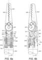
- the pulley arrangement is better illustrated in figures 6a and 6b .
- the supporting body 509 is not shown in figures 6a and 6b in order to more clearly illustrate the pulley arrangement.
- the pulley arrangement comprises a first set of pulleys 601.
- the first set of pulleys 601 is rotatable about the first axis 510.
- the pulley arrangement further comprises a second set of pulleys 602.
- the pulley arrangement further comprises a pair of redirecting pulleys 603.
- the pulley arrangement is more clearly illustrated in figure 7 .
- the supporting body, the first joint and the first pair of driving elements have all been omitted from figure 7 in order to more clearly illustrate the pulley arrangement.
- the second set of pulleys comprises a first pulley 701 and a second pulley 702.
- the first pulley 701 is rotatable about a third axis 703 which is parallel to the first axis 510.
- the third axis 703 is offset from the first axis 510 both in the longitudinal direction of the shaft and also transverse to the longitudinal direction of the shaft.
- the second pulley 702 is rotatable about a fourth axis 704 which is parallel to the first axis 510.
- the fourth axis 704 is offset from the first axis 510 both in the longitudinal direction of the shaft and also transverse to the longitudinal direction of the shaft.
- the third and fourth axes are parallel but offset from each other.
- the third axis 703 and fourth axis 704 are in the same plane perpendicular to the longitudinal direction of the shaft.
- Figure 8 illustrates the distal end of the surgical instrument from a different view which more clearly shows the offset axes of the first pulley 701 and the second pulley 702 of the second set of pulleys.
- first pulley 701 and second pulley 702 of the second set of pulleys 602 are located on opposing sides of the first joint 506 in a longitudinal direction of the shaft 504.
- the first pulley 701 and second pulley 702 are located on opposing sides of the first pair of driving elements A1,A2.
- the second set of pulleys is located between the first set of pulleys and the instrument interface end of the shaft.
- the second set of pulleys is located within the shaft as shown in the figures.
- the second set of pulleys may be located within the articulation between the first joint 506 and the second joint 507.
- the distance between the first and second joints is reduced compared to the alternative arrangement in which the second set of pulleys are located in the articulation, thereby reducing the stiffness of the supporting body 509 required to maintain accurate positioning of the end effector 501.
- the first set of pulleys 601 comprises a first pulley 705 and a second pulley 706. Both the first pulley 705 and the second pulley 706 rotate about the first axis 510.
- the first pulley 705 and the second pulley 706 of the first set of pulleys are located on opposing sides of the first joint 506 in a longitudinal direction of the shaft 504.
- the first pulley 705 and the second pulley 06 are located on opposing ends of the first axis 510.
- the first pulley 705 and the second pulley 706 are located on opposing sides of the first pair of driving elements A1,A2.
- the second pair of driving elements B1,B2 is constrained to move around opposing sides of the first pulley 705 and the second pulley 706 of the first set of pulleys 601.
- the second pair of driving elements B1,B2 is constrained to move around opposing sides of the first pulley 701 and the second pulley 702 of the second set of pulleys 601.
- the second pair of driving elements is constrained to move around opposing sides of the first pulley 705 of the first set of pulleys 601 and the first pulley 701 of the second set of pulleys 602.
- the second pair of driving elements is constrained to move around opposing sides of the second pulley 706 of the first set of pulleys 601 and the second pulley 702 of the second set of pulleys 602.
- the third pair of driving elements C1,C2 is constrained to move around opposing sides of the first pulley 705 and the second pulley 706 of the first set of pulleys 601.
- the third pair of driving elements C1,C2 is constrained to move around opposing sides of the first pulley 701 and the second pulley 702 of the second set of pulleys 601.
- the third pair of driving elements is constrained to move around opposing sides of the first pulley 705 of the first set of pulleys 601 and the first pulley 701 of the second set of pulleys 602.
- the third pair of driving elements is constrained to move around opposing sides of the second pulley 706 of the first set of pulleys 601 and the second pulley 702 of the second set of pulleys 602.
- the second and third pairs of driving elements are each constrained to extend over the first joint 506 in order to reach the second and third joints respectively.
- the first one of the second pair of driving elements B1 passes over one side of the first pulley 705 of the first set of pulleys on the first joint axis 510
- the second one of the second pair of driving elements B2 passes over an opposing side of the second pulley 706 of the first set of pulleys on the first joint axis 510, so that whatever rotation there is of the supporting body 509 about the first joint 506, the length of the second pair of driving elements B1,B2 is maintained the same.
- the first one of the third pair of driving elements C1 passes over one side of the second pulley 706 of the first set of pulleys on the first joint axis 510
- the second one of the third pair of driving elements C2 passes over an opposing side of the first pulley 705 of the first set of pulleys on the first joint axis 510, so that whatever rotation there is of the supporting body 509 about the first joint 506, the length of the third pair of driving elements C1,C2 is maintained the same.
- the length of the second pair of driving elements is the same as the length of the third pair of driving elements for all rotation angles of the supporting body 509 about the first joint 506.
- the second pair of driving elements and the third pair of driving elements remain taut. They are never slack. Thus, there is no backlash when articulating any of the joints of the surgical instrument. Thus, full control of all three degrees of freedom of movement of the surgical instrument is achieved in every configuration of the surgical instrument.
- each pulley of the first set of pulleys 601 comprises a pair of pulley elements.
- the first pulley 705 comprises an inside pulley element 708 and an outside pulley element 709.
- Inside pulley element 708 is located between the outside pulley element 709 and the first pair of driving elements A1,A2.
- inside pulley element 708 abuts outside pulley element 709.
- the inside pulley element 708 may be fast with the outside pulley element 709.
- the inside pulley element 708 may be integrally formed with the outside pulley element 709.
- the second pulley 706 comprises an inside pulley element 710 and an outside pulley element 711.
- Inside pulley element 710 is located between the outside pulley element 711 and the first pair of driving element A1,A2. Suitably, inside pulley element 710 abuts outside pulley element 711.
- the inside pulley element 710 may be fast with the outside pulley element 711.
- the inside pulley element 710 may be integrally formed with the outside pulley element 711.
- Each pulley element comprises a groove for seating a driving element.
- each pulley of the second set of pulleys 602 comprises a pair of pulley elements.
- the first pulley 701 comprises an inside pulley element 712 and an outside pulley element 713.
- Inside pulley element 712 is located between the outside pulley element 713 and the first pair of driving elements A1,A2.
- inside pulley element 712 abuts outside pulley element 713.
- the inside pulley element 712 may be fast with the outside pulley element 713.
- the inside pulley element 712 may be integrally formed with the outside pulley element 713.
- the second pulley 702 comprises an inside pulley element 714 and an outside pulley element 715.
- Inside pulley element 714 is located between the outside pulley element 715 and the first pair of driving element A1,A2. Suitably, inside pulley element 714 abuts outside pulley element 715.
- the inside pulley element 714 may be fast with the outside pulley element 715.
- the inside pulley element 714 may be integrally formed with the outside pulley element 715.
- Each pulley element comprises a groove for seating a driving element.
- the second pair of driving elements B1,B2 is constrained to move around the inside pulley element 712 of the first pulley of the second set of pulleys and the outside pulley element 715 of the second pulley of the second set of pulleys.
- the second pair of driving elements B1, B2 is constrained to move around the inside pulley element 708 of the first pulley of the first set of pulleys and the outside pulley element 711 of the second pulley of the first set of pulleys.
- the third pair of driving elements C1,C2 is constrained to move around the outside pulley element 713 of the first pulley of the second set of pulleys and the inside pulley element 714 of the second pulley of the second set of pulleys.
- the third pair of driving elements C1,C2 is constrained to move around the outside pulley element 709 of the first pulley of the first set of pulleys and the inside pulley element 710 of the second pulley of the first set of pulleys.
- the second pair of driving elements B1,B2 has a symmetrically opposing path around the first and second sets of pulleys 601, 602 than the third pair of driving elements C1,C2.
- the path of the second pair of driving elements B1,B2 about the pulley arrangement is rotationally symmetrical about the longitudinal axis of the shaft 511 to the path of the third pair of driving elements C1,C2 about the pulley arrangement.
- the second and third pairs of driving elements B1,B2 and C1,C2 emerge from the second set of pulleys 602 into the distal end of the shaft in a symmetrical arrangement.
- the driving elements B1 and C2 emerge adjacent to each other on one side of the shaft, and the driving elements C1 and B2 emerge adjacent to each other on an opposing side of the shaft.
- the arrangement of driving elements B1 and C2 in the shaft is rotationally symmetrical to the arrangement of driving elements C1 and B2 in the shaft, about the longitudinal axis of the shaft 511.
- the second set of pulleys 602 redirects the second and third pairs of driving elements from the first set of pulleys 601 into the shaft in this manner.
- Figure 7 illustrates the distal end of the surgical instrument in five different configurations.
- Configuration (c) is the straight configuration previously mentioned, in which the end effector is aligned with the instrument shaft.
- rotation about the first joint has occurred relative to configuration (c).
- no rotation about either the second or third joint has occurred relative to configuration (c).
- the driving element A2 (not shown) is pulled in order to cause the rotation about the first axis 510 leading to the arrangement of configuration (b).
- the driving element A2 is further pulled to cause further rotation about the first axis 510 to lead to the arrangement of configuration (a).
- the driving element A1 (not shown) is pulled in order to cause rotation about the first axis 510 in an opposing direction to that in configurations (a) and (b), thereby leading to the arrangement of configuration (d).
- the driving element A1 is further pulled to cause further rotation about the first axis 510 to lead to the arrangement of configuration (e).
- Rotation of the end effector 501 about the first axis 510 is bounded by the maximum travel of the first pair of driving elements A1,A2 about the first joint 506.
- Configuration (a) shows the end effector 501 at maximum rotation about the first axis 510 in one direction
- configuration (e) shows the end effector 501 at maximum rotation about the first axis 510 in the opposing direction.
- the maximum rotation angle relative to the longitudinal axis of the shaft 511 in both configurations is the angle ⁇ .
- the second set of pulleys 602 are located relative to the first set of pulleys 601 so as to ensure that the second and third pairs of driving elements are retained in contact with both the first set of pulleys 601 and the second set of pulleys 602 even at the maximum rotation angle ⁇ .
- the end effector 501 For all rotation angles of the end effector 501 about the first axis 510, the end effector 501 always lies within the cone defined by the tangential line connecting the first pulley 701 of the second set of pulleys and the first pulley 705 of the first set of pulleys. That tangential line is the path taken by the driving element.
- the end effector 501 lies in this cone when the second and third joints are retained in the straight configurations of figures 5a and 5b , as shown in all the configurations of figure 7 .
- the driving elements B2 and C1 would lose contact with the first set of pulleys 601 in configuration (a).
- the driving elements B1 and C2 would lose contact with the first set of pulleys 601 in configuration (e).
- the second and third pairs of driving elements are retained in contact with the first and second sets of pulleys for all rotation angles of the end effector relative to the longitudinal axis of the shaft.
- the length of the second pair of driving elements B1,B2 will be maintained the same.
- the length of the third pair of driving elements C1,C2 will be maintained the same.
- the second set of pulleys enable tension to be retained in the second and third driving elements regardless of how the first joint 506 is driven about the first axis 510.
- control of the second and third driving elements is retained regardless of how the first joint 506 is driven about the first axis 510.
- the pulley arrangement further comprises a pair of redirecting pulleys 716,717. These redirecting pulleys are in the articulation 505 between the first joint 506 and the second and third joints 507, 513.
- the redirecting pulleys are positioned so as to redirect the second pair of driving elements B1,B2 from the first set of pulleys 601 to the second joint 507 and to redirect the third pair of driving elements C1,C2 from the first set of pulleys 601 to the third joint 513.
- the second pair of driving elements B1,B2 is constrained to move around the first redirecting pulley 716.
- the first redirecting pulley 716 rotates about a first redirecting pulley axis 718.
- the first redirecting pulley axis 718 is at an angle ⁇ to the first axis 510.
- the angle ⁇ is such that the first one of the second pair of driving elements B1 is redirected from a take-off point of the first pulley 705 of the first set of pulleys 601 to a pick-up point 721 on the second joint 507.
- the first redirecting pulley 716 comprises a groove which seats the driving element B1.
- the third pair of driving elements C1,C2 is not constrained to move around the first redirecting pulley 716.
- the second one of the third pair of driving elements C2 does pass by the first redirecting pulley 716 between its take-off point of the third joint 513 and its pick-up point on the first pulley 705 of the first set of pulleys 601.
- the driving element C2 may be partially enclosed by the first redirecting pulley 716.
- the driving element C2 may partially pass between the wings of the groove of the first redirecting pulley 716, but the driving element C2 is not seated in the groove of the first redirecting pulley 716.
- the third pair of driving elements C1,C2 is constrained to move around the second redirecting pulley 717.
- the second redirecting pulley 717 rotates about a second redirecting pulley axis 719.
- the second redirecting pulley axis 719 is at an angle ⁇ to the first axis 510.
- the angle ⁇ is such that the first one of the third pair of driving elements C1 is redirected from a take-off point 720 of the second pulley 706 of the first set of pulleys 601 to a pick-up point on the third joint 513.
- the second redirecting pulley 717 comprises a groove which seats the driving element C1.
- the second pair of driving elements B1,B2 is not constrained to move around the second redirecting pulley 717.
- the second one of the second pair of driving elements B2 does pass by the second redirecting pulley 717 between its take-off point 720 of the second joint 507 and its pick-up point on the second pulley 706 of the first set of pulleys 601.
- the driving element B2 may be partially enclosed by the second redirecting pulley 717.
- the driving element B2 may partially pass between the wings of the groove of the second redirecting pulley 717, but the driving element B2 is not seated in the groove of the second redirecting pulley 717.
- a take-off point is the point at which a driving element loses contact with a pulley.
- a pick-up point is the point at which a driving element first contacts a pulley.
- the take-off point of the driving element from the first pulley and the pick-up point of the driving element on the second pulley are points on a line which is tangential to both the first pulley and the second pulley, the take-off point being where that tangential line intersects the first pulley, and the pick-up point being where that tangential line intersects the second pulley.
- the tangential line has a thickness equal to the thickness of the driving element, with the take-off point being where one side of the tangential line meets the first pulley, and the pick-up point being where the other side of the tangential line meets the second pulley.
- the redirecting pulley 716 causes the driving element B1 to wrap more fully around the second joint 507 than would happen if the redirecting pulley 716 was not there, thereby increasing the length of engagement between the driving element B1 and the second joint 507.
- the driving element B1 has a greater travel around the second joint 507, and is hence able to cause a larger rotation of the end effector element 502 about the second axis 512 than would be possible without the redirecting pulley 716.
- the redirecting pulley 716 causes the pick-up point of the driving element B1 on the second joint 507 to change relative to where it would have been without the redirecting pulley 716.
- the redirecting pulley 717 causes the driving element C1 to wrap more fully around the third joint 513 than would happen if the redirecting pulley 717 was not there, thereby increasing the length of engagement between the driving element C1 and the third joint 513.
- the driving element C1 has a greater travel around the third joint 513, and is hence able to cause a larger rotation of the end effector element 503 about the second axis 512 than would be possible without the redirecting pulley 717.
- the redirecting pulley 717 causes the pick-up point of the driving element C1 on the third joint 513 to change relative to where it would have been without the redirecting pulley 717.
- each redirecting pulley is located towards the outside edge of the articulation, on opposing sides of the articulation. This is more easily seen on figure 5a . As seen in figure 6a , each redirecting pulley is located between the longitudinal axis of the articulation and the external profile of the articulation, on opposing sides of the articulation. Suitably, the diameter of each redirecting pulley is maximised for the space available.
- the redirecting pulley is as large as possible, whilst enabling one driving element to engage the pulley on one side of the pulley and another driving element to pass next to the pulley on the opposing side of the pulley without snagging, the pulley and the two driving elements being encapsulated within the profile of the articulation.
- the first redirecting pulley 716 is located in a plane defined by the following three points: (i) the desired take-off point of driving element B1 from the first pulley 705 of the first set of pulleys 601, (ii) the desired pick-up point of driving element B1 on the second joint 507, and (iii) a point on the boundary of the articulation, the point being such that the first redirecting pulley 716 is encapsulated within the boundary of the articulation when located in the plane.
- the first redirecting pulley 716 is as large as possible whilst still being located in this plane, encapsulated within the profile of the articulation, not impeding the path of the driving element C2, and enabling driving element B1 to freely move around it.
- the second redirecting pulley 717 is located in a plane defined by the following three points: (i) the desired take-off point of driving element C1 from the second pulley 706 of the first set of pulleys 601, (ii) the desired pick-up point of driving element C1 on the third joint 513, and (iii) a point on the boundary of the articulation, the point being such that the second redirecting pulley 717 is encapsulated within the boundary of the articulation when located in the plane.
- the second redirecting pulley 717 is as large as possible whilst still being located in this plane, encapsulated within the profile of the articulation, not impeding the path of the driving element B2, and enabling driving element C1 to freely move around it.
- the desired take-off points and pick-up points are determined so as to allow the desired travel of the driving elements around the second and third joints so as to allow the desired maximum rotation of the end effector elements about the second axis.
- the first and second redirecting pulleys are located in different planes.
- those planes may be symmetrical about a plane which is perpendicular to the first axis 510.
- Those planes may be rotationally symmetrical about a plane which is perpendicular to the first axis 510.
- those planes may be rotationally symmetrical about a line in a plane which is perpendicular to the first axis 510.
- those planes are rotationally symmetrical about the longitudinal axis of the shaft 511. This is second order rotational symmetry.
- Those planes may be a reflection of each other in the plane which is perpendicular to the first axis 510.
- the end effector elements 502 and 503 are rotationally symmetrical, and the paths of the driving elements about the joints 507 and 513 are rotationally symmetrical.
- the axes of the end effector elements 502 and 503 may be rotationally asymmetrical and/or the paths of the driving elements about the joints 507 and 513 may be asymmetrical.
- the paths of the driving elements about the joints 507 and 513 may be asymmetrical as a result of the joints having different diameters (to enable different tension ratios) and/or being positioned at different offsets from the centreline of the supporting body 509.
- first and second redirecting pulleys 716 and 717 would not be rotationally symmetric. They would have different sizes and/or different positions in order to cause the driving elements to have the desired take-off points and pick-up points as previously described.
- the whole pulley arrangement comprising the first set of pulleys, the second set of pulleys and the redirecting pulleys is symmetrical about a plane which is perpendicular to the first axis 510.
- a first partial arrangement comprising the first pulley of the first set of pulleys 705, the first pulley of the second set of pulleys 701, and the first redirecting pulley 716 is rotationally symmetrical to a second partial arrangement comprising the second pulley of the first set of pulleys 706, the second pulley of the second set of pulleys 702, and the second redirecting pulley 717 about a plane which is perpendicular to the first axis 510.
- the first partial arrangement is a reflection of the second partial arrangement in the mentioned plane which is perpendicular to the first axis 510.
- the second pair of driving elements B1,B2 is constrained to move around the pulley arrangement in a rotationally symmetrically opposing manner to that in which the third pair of driving elements C1,C2 is constrained to move around the pulley arrangement. Since the pulley arrangement has the described symmetry, the second and third driving elements that are constrained to move symmetrically around the pulley arrangement also have the same symmetry. Thus, the path of the second pair of driving elements B1,B2 about the pulley arrangement is rotationally symmetrical to the path of the third pair of driving elements C1,C2 about the pulley arrangement.
- the first and second redirecting pulleys are mounted on the supporting body 509.
- Figure 10 illustrates the supporting body 509 and the redirecting pulleys in isolation.
- Each redirecting pulley is mounted to a surface of the supporting body 509 by a spindle.
- the spindle 1001 secures the first redirecting pulley 716 to the supporting body 509.
- a spindle 1102 also secures the second redirecting pulley 717 to the supporting body 509.
- the supporting body 509 has a bevelled surface 1101 onto which the first redirecting pulley 716 is mounted.
- the first redirecting pulley 716 has a mounting surface 1104 which faces the bevelled surface 1101 of the supporting body 509.
- the mounting surface 1104 is flush with the bevelled surface 1101.
- the first redirecting pulley has an opposing surface 1105 which opposes the mounting surface 1104.
- the opposing surface 1105 is parallel to the mounting surface 1104.
- the supporting body 509 has a further bevelled surface onto which the second redirecting pulley 717 is mounted by spindle 1103.
- the second redirecting pulley 717 has a mounting surface 1106 which faces the bevelled surface 1102 of the supporting body 509.
- the mounting surface 1106 is flush with the bevelled surface 1102.
- the second redirecting pulley has an opposing surface 1107 which opposes the mounting surface 1102.
- the opposing surface 1107 is parallel to the mounting surface 1102.
- the bevelled surfaces of the supporting body 509 are not parallel to the longitudinal axis of the supporting body.
- the bevelled surface 1101 of the supporting body 509 is located in a plane 1108 parallel to the plane 1109 in which the first redirecting pulley 716 is located.
- the bevelled surface 1101 is located in a plane 1108 parallel to the plane 1109 defined by the following three points: (i) the desired take-off point of driving element B1 from the first pulley 705 of the first set of pulleys 601, (ii) the desired pick-up point of driving element B1 on the second joint 507, and (iii) a point on the boundary of the articulation, the point being such that the first redirecting pulley 716 is encapsulated within the boundary of the articulation when located in the plane 1109.
- the plane 1108 of the bevelled surface 1101 is offset from the plane 1109 defined by these points by half the width of the first redirecting pulley 716, illustrated as d 1 in figure 11 .
- the bevelled surface 1102 of the supporting body 509 is located in a plane 1110 parallel to the plane 1111 in which the second redirecting pulley 717 is located.
- the bevelled surface 1102 is located in a plane 1110 parallel to the plane 1111 defined by the following three points: (i) the desired take-off point of driving element C1 from the second pulley 706 of the first set of pulleys 601, (ii) the desired pick-up point of driving element C1 on the third joint 513, and (iii) a point on the boundary of the articulation, the point being such that the second redirecting pulley 717 is encapsulated within the boundary of the articulation when located in the plane 1111.
- the plane 1110 of the bevelled surface 1101 is offset from the plane 1111 defined by these points by half the width of the second redirecting pulley 717, illustrated as d 2 in figure 11 .
- each redirecting pulley is mounted to the corresponding bevelled surface of the supporting body by a spindle.
- the spindle comprises a spindle body and a spindle head.
- the spindle body passes through a central aperture of the redirecting pulley.
- the central aperture is a through-hole which extends perpendicularly between the mounting surface and the opposing surface of the redirecting pulley.
- the spindle body passes through the central aperture of the redirecting pulley into a bore of the supporting body.
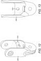
- Figures 12 and 13 illustrate the supporting body 509 in isolation. An exemplary implementation of the bore of the supporting body is depicted in these figures.
- the bore is a recess in the supporting body which tapers to a point.
- the spindle body passes through the initial opening of the bore and securely lodges in the tapered section.
- the spindle head is bigger than the central aperture of the redirecting pulley, and thus is unable to pass through the central aperture of the redirecting pulley. Consequently, the spindle head secures the redirecting pulley flush against the bevelled surface of the supporting body.
- the spindle head contacts at least a portion of the opposing surface of the redirecting pulley, through which contact the redirecting pulley is retained against the bevelled surface.
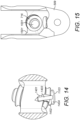
- the diameter of the bore 1401 through the supporting body is greater than the diameter of the spindle body 1403.
- the diameter of the central aperture 1402 of the redirecting pulley may be greater than the diameter of the spindle body 1403.
- the spindle body may loosely fit through the central aperture of the redirecting pulley.
- the spindle body loosely fits through the bore of the supporting body except for in the region in which it is secured to the bore, in the example above the tapered section.
- the bore through the supporting body is created by drilling through the bevelled surface of the supporting body during manufacture. Since the opening of the bore in the bevelled surface has a greater diameter than the spindle body, the precision of the angle at which the supporting body is drilled to create the bore is not critical.
- the spindle sits in the bore at the correct angle for the redirecting pulley to sit flush with the bevelled surface. It would have been critical that the angle of the bore was drilled very accurately if the fit of the spindle body through the bore was a tight fit and was the means by which the redirecting pulley was caused to rotate about the redirecting pulley axis 718,719. In that case the pulley would have been mounted tight on to the spindle which would have been mounted tight into the bore to stop the pulley from precessing. Thus, there would have been no room for manufacturing deviations in the angle at which the hole was drilled through the supporting body.
- the redirecting pulley is caused to rotate about the redirecting pulley axis 718,719 as a result of the redirecting pulley being held flush against a bevelled surface of the supporting body 509 which is perpendicular to the redirecting pulley axis 718,719.
- a bevelled surface of the supporting body 509 which is perpendicular to the redirecting pulley axis 718,719.
- the bevelled surfaces 1101 and 1102 of the supporting body are not parallel to each other.
- the bevelled surfaces may be symmetrical about a plane which is perpendicular to the first axis 510.
- the bevelled surfaces may be rotationally symmetrical about a plane which is perpendicular to the first axis 510.
- the bevelled surfaces may be rotationally symmetrical about a line in a plane which is perpendicular to the first axis 510.
- the bevelled surfaces are rotationally symmetrical about the longitudinal axis of the shaft 511. This is second order rotational symmetry.
- the bevelled surfaces may be a reflection of each other in the plane which is perpendicular to the first axis 510.
- the supporting body 509 comprises grooves adjacent to each bevelled surface for seating a driving element.
- the supporting body comprises a groove 1501 adjacent the bevelled surface 1101 for seating the second one C2 of the third pair of driving elements.
- the driving element C2 is seated in the groove 1501 and partially enclosed by the first redirecting pulley 716.
- the supporting body comprises a groove 1502 adjacent the bevelled surface 1102 for seating the second one B2 of the second pair of driving elements. Groove 1502 is shown in figure 11 .
- the driving element B2 is seated in the groove 1502 and partially enclosed by the second redirecting pulley 717.
- the first, second and third pairs of driving elements extend through the instrument shaft from the distal end of the shaft connected to the articulation to the proximal end of the shaft connected to a drive mechanism of the instrument interface.
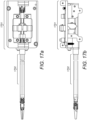
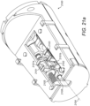
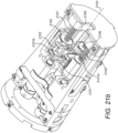
- Figures 17a and 17b illustrate two views of the first, second and third pairs of driving elements extending from the described articulation to an exemplary instrument interface 1701.
- the second and third pairs of driving elements overlap in the shaft so as to emerge from the proximal end of the shaft in a different arrangement to that at which they are in at the distal end of the shaft.
- Figure 16 illustrates cross-sections of the shaft depicting the positions of the driving elements.
- driving element B1 and driving element C1 have not extended down the shaft parallel to the longitudinal axis of the shaft 511. Instead, driving element B1 and driving element C1 have overlapped each other during their extent in the shaft. This overlapping occurs without the driving elements B1 and C1 clashing because of their offset positions in configuration (a) owing to the pulleys of the second set of pulleys 602 having offset axes.
- Driving element B2 has moved a little in the shaft, but remained on the same side of the shaft as in configuration (a), so as to emerge at the proximal end of the shaft adjacent to driving element B1.
- Driving element C2 has moved a little in the shaft, but remained on the same side of the shaft as in configuration (a), so as to emerge at the proximal end of the shaft adjacent to driving element C1.
- a driving element may be a uniform component having the same shape and size along its length and constructed of the same material along its length.
- the driving element may be composed of different portions.
- the portion of the driving element which engages components of the instrument interface (such as pulleys and interface elements) is flexible.
- the portion of the driving element which engages components of the distal end of the surgical instrument (such as the pulleys and joints in the articulation) is flexible.
- spokes 1702 illustrated in figures 17a and 17b are between these two flexible portions.
- each pair of driving elements comprises two spokes and two flexible portions.
- Each pair of driving elements forms a loop.
- the loop comprises alternating spokes and flexible portions.
- the two spokes are predominantly or wholly enclosed in the instrument shaft.
- FIG 18 depicts a straight configuration of the surgical instrument in which the end effector 501 is aligned with the shaft 504.
- the distal flexible portion of driving element A1 terminates in the spoke A1s at a point 1801 along the longitudinal direction x of the shaft.
- the longitudinal direction x is the direction of the longitudinal axis 511 of the shaft.
- the distal flexible portion of driving element A2 terminates in the spoke A2s at a point 1802 along the longitudinal direction x of the shaft.
- the distal flexible portion of driving element B1 terminates in the spoke B1s at a point 1803 along the longitudinal direction x of the shaft.
- the distal flexible portion of driving element C1 terminates in the spoke C1s at a point 1804 along the longitudinal direction x of the shaft.
- the distal flexible portions of driving elements B2 and C2 terminate in their respective spokes further towards the proximal end of the shaft, as can be seen in figure 17a .
- the longitudinal positions 1801, 1802, 1803 and 1804 at which the distal flexible portions of the driving elements terminate in the distal ends of the spokes are not coincident when the instrument is in the straight configuration depicted. Instead, the longitudinal positions 1801, 1802, 1803 and 1804 are offset from each other.
- the distal ends of the spokes of the driving elements are offset along the longitudinal direction of the shaft when the instrument is in the straight configuration.
- the distal ends of adjacent spokes are offset along the longitudinal direction of the shaft in the straight configuration.
- the distal ends of spokes which are not adjacent to each other may be coincident along the longitudinal direction of the shaft in the straight configuration.
- the non-adjacent spokes A1s and A2s both terminate at the same point 1801,1802 along the longitudinal direction of the shaft.
- the distal ends of the spokes of the driving elements are offset along the longitudinal direction of the shaft in every configuration of the surgical instrument.
- the distal ends of adjacent spokes are offset along the longitudinal direction of the shaft in every configuration of the surgical instrument.
- FIG 19a the spokes of the driving elements A1, A2, B1 and C1 are visible, labelled as A1s, A2s, B1s and C1s respectively.
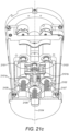
- Figure 19a depicts a non-straight configuration of the surgical instrument in which the end effector 501 is not aligned with the shaft 504.
- the proximal flexible portion of driving element A1 terminates in the spoke A1s at a point 1901 along the longitudinal direction x of the shaft.
- the longitudinal direction x is the direction of the longitudinal axis 511 of the shaft.
- the proximal flexible portion of driving element A2 terminates in the spoke A2s at a point 1904 along the longitudinal direction x of the shaft.
- the proximal flexible portion of driving element B1 terminates in the spoke B1s at a point 1902 along the longitudinal direction x of the shaft.
- the proximal flexible portion of driving element C1 terminates in the spoke C1s at a point 1903 along the longitudinal direction x of the shaft.
- the proximal flexible portions of driving elements B2 and C2 terminate in their respective spokes further towards the distal end of the shaft, as can be seen in figure 17a .
- the spokes may terminate in the proximal flexible portions inside the shaft, as is the case in the example shown for driving elements B2 and C2.
- the spokes may terminate in the proximal flexible portions inside the instrument interface, as is the case in the example shown for driving elements A1, A2, B1 and C1.
- spokes may terminate in the proximal flexible portions inside the shaft and some spokes may terminate in the proximal flexible portions inside the instrument interface.
- the driving elements B2 and C2 engage pulleys as they enter the instrument interface from the shaft, thus the spokes of driving elements B2 and C2 terminated in their proximal flexible portions in the shaft (not shown) to enable the proximal flexible portions to engage the pulleys.
- Driving elements A1, A2, B1 and C1 all extend some distance into the instrument interface before engaging with components of the instrument interface, thus the spokes of driving elements A1, A2, B1 and C1 are able to extend into the instrument interface.
- the longitudinal positions 1901, 1902, 1903 and 1904 at which the proximal flexible portions of the driving elements terminate in the proximal ends of the spokes are not coincident. Instead, the longitudinal positions 1901, 1902, 1903 and 1904 are offset from each other.
- the proximal ends of the spokes of the driving elements are offset along the longitudinal direction of the shaft when the instrument is in the configuration shown.
- the proximal ends of the spokes of the driving elements are offset along the longitudinal direction of the shaft for the straight configuration of the instrument.
- the proximal ends of adjacent spokes are offset along the longitudinal direction of the shaft in the straight configuration.
- proximal ends of spokes which are not adjacent to each other may be coincident along the longitudinal direction of the shaft in the straight configuration.
- the non-adjacent spokes B1s and C1s both terminate at the same point 1902,1903 along the longitudinal direction of the shaft.
- the proximal ends of the spokes of the driving elements are offset along the longitudinal direction of the shaft in every configuration of the surgical instrument.
- the distal ends of adjacent spokes are offset along the longitudinal direction of the shaft in every configuration of the surgical instrument.
- the longitudinal positions of the proximal ends of the spokes are selected such that the spokes do not collide when the instrument is being articulated.
- the longitudinal positions of the proximal ends of the spokes in the straight configuration of the instrument are such that for any configuration of the end effector, no portion of any driving element contacts a portion of another driving element.
- Each pair of driving elements engages a single instrument interface element in the instrument interface.
- Each driving element engages an instrument interface element in the instrument interface.
- each driving element engages its own instrument interface elements.
- a single instrument interface element drives a pair of driving elements.
- Each driving element is driven independently by a single instrument interface.
- there may be a compound driving motion in which more than one instrument interface element drives a single driving element, a single instrument interface element drives more than one pair of driving elements, or a plurality of instrument interface elements collectively drive a plurality of driving elements.
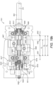
- Figure 19b illustrates a first instrument interface element 1905 which engages the first pair of driving elements A1,A2.
- a second instrument interface element 1906 engages the second pair of driving elements B1,B2.
- a third instrument interface element 1907 engages the third pair of driving elements C1,C2.
- each driving element is secured to its associated instrument interface element. In other words, each driving element is fast with its associated instrument interface element.
- the instrument interface 1701 has a significantly larger profile than the instrument shaft 504.
- the instrument shaft has a circular cross-section having a diameter of less than or the same as 5mm, whereas a corresponding cross-section through the instrument interface may be larger than this.
- the instrument interface comprises an internal portion and an external portion.
- the internal portion is bounded by the dotted line 1950 (shown in figures 19a and 19b ).
- the external portion is the remainder of the instrument interface which is not in the internal portion.
- the internal portion is within the projected profile of the shaft. In other words, the internal portion is the part of the instrument interface that would have been encompassed had the profile of the shaft continued within the instrument interface.
- the external portion is outside of the projected profile of the shaft.
- the shaft has a constant circular cross-section
- the internal portion is a cylinder having the same circular cross-section as the shaft, and having the same longitudinal axis 511 as the shaft.
- the internal portion is an extrapolation of the constant cross-section of the shaft in the instrument interface.
- the internal portion 1950 is shown from the side in figure 19a and from the top in figure 19b .
- the instrument interface elements 1905, 1906 and 1907 are dispersed across the width of the instrument interface as shown in figure 19b .
- one instrument interface element 1905 is within the internal portion 1950 of the instrument interface.
- the part of the instrument interface element 1905 which engages the driving element is within the internal portion 1950 of the instrument interface.
- the instrument interface element 1905 as a whole may be substantially within the internal portion 1950 of the instrument interface, as shown in figure 19b .
- the instrument interface element 1905 as a whole may be wholly within the internal portion 1950 of the instrument interface.
- the instrument interface element 1905 is aligned with the longitudinal axis 511 of the shaft 504. In an exemplary arrangement, only one instrument interface element is located within the internal portion of the instrument interface.
- the remainder of the instrument interface elements 1906, 1907 are within the external portion of the instrument interface. These other instrument interface elements 1906, 1907 are located on either side of the aligned instrument interface element 1905. Specifically, the other instrument interface elements 1906, 1907 are located on either side of the aligned instrument interface element 1905 in a direction perpendicular to the longitudinal axis of the shaft 511. The instrument interface elements 1906 and 1907 are not aligned with the longitudinal axis 511 of the shaft 504. The instrument interface elements 1906 and 1907 are constrained to move parallel to the longitudinal axis 511 of the shaft 504, since they are constrained to move along rails 1929 and 1930 respectively.
- Instrument interface element 1905 engages a first pair of driving elements A1, A2.
- the pair of driving elements A1, A2 lie wholly within the internal portion 1950.
- the pair of driving elements A1, A2 lie wholly parallel to the longitudinal axis of the shaft 511.
- only instrument interface element 1905 engages its pair of driving elements A1, A2 in the internal portion 1950 of the instrument interface.
- Instrument interface element 1906 engages a second pair of driving elements B1, B2.
- the instrument interface element 1906 engages the second pair of driving elements B1, B2 in the external portion of the instrument interface.
- Instrument interface element 1907 engages a third pair of driving elements C1, C2.
- the instrument interface element 1907 engages the third pair of driving elements C1, C2 in the external portion of the instrument interface.
- a pulley arrangement is used to shift the driving elements over to engage with the instrument interface elements which are in the external portion.
- Each pair of driving elements engages a first pair of pulleys to shift it over from the proximal end of the shaft 504 to its respective instrument interface element, and a second pair of pulleys to shift it back from alignment with the instrument interface element to alignment with the shaft 504.
- the second pair of driving elements B1,B2 emerges from the proximal end of the shaft in a direction aligned with the shaft.
- the driving elements B1,B2 do not run exactly parallel to the longitudinal axis 511 of the shaft 504 as a result of the direction changes described with respect to figure 16 .
- the second pair of driving elements B1, B2 is then constrained to move around pulley pair 1908 and 1909 to shift it from where it emerges from the shaft 504 to engagement with the second instrument interface element 1906.
- the second pair of driving elements B1, B2 emerges from the pulley pair 1908 and 1909 in a direction parallel to and offset from the direction that the second pair of driving elements B1, B2 emerges from the proximal end of the shaft.
- the second pair of driving elements B1,B2 is constrained to move around pulley pair 1910 and 1911 to shift it from alignment with the second instrument interface element 1906 to alignment with the shaft 504.
- the third pair of driving elements C1, C2 emerges from the proximal end of the shaft in a direction aligned with the shaft.
- the driving elements C1,C2 do not run exactly parallel to the longitudinal axis 511 of the shaft 504 as a result of the direction changes described with respect to figure 16 .
- the third pair of driving elements C1,C2 is then constrained to move around pulley pair 1912 and 1913 to shift it from where it emerges from the shaft 504 to engagement with the third instrument interface element 1907.
- the third pair of driving elements C1, C2 emerges from the pulley pair 1912 and 1913 in a direction parallel to and offset from the direction that the third pair of driving elements C1, C2 emerges from the proximal end of the shaft.
- the third pair of driving elements C1,C2 is constrained to move around pulley pair 1914 and 1915 to shift it from alignment with the third instrument interface element 1907 to alignment with the shaft 504.
- pair of driving elements A1, A2 engage with the first instrument interface element 1905 which is within the internal portion.
- Pair of driving elements A1, A2 drive rotation of the articulation, and hence the end effector, about the first axis 510 (see figure 5a ).
- first joint 506 There is a smaller range of motion about first joint 506 than there is about second joint 507 and third joint 513.
- the first instrument interface element 1905 is linearly displaceable through a maximum distance d 1 minus the length of the first instrument interface element 1905, which is smaller than the maximum displacement of the second instrument interface element 1906 d 2 minus the length of the second instrument interface element 1906, and smaller than the maximum displacement of the third instrument interface element 1907 d 3 minus the length of the third instrument interface element 1907. Since motion about the first joint 506 is controlled via a shorter range of travel of the instrument interface element than the second and third joints, greater sensitivity of that motion is preferred. Cables may slip and/or stretch over pulleys. Thus, the simplest cabling scheme is preferably utilised for transferring motion between the first instrument interface element and the first joint 506.
- the first pair of driving elements is not constrained to pass around any intervening pulleys between the first joint 506 and the first instrument interface element 1905.
- Each instrument interface element is displaceable within the instrument interface. Since each instrument interface element is secured to a corresponding pair of driving elements, a displacement of the instrument interface element is transferred to a displacement of the pair of driving elements. Suitably, each instrument interface element is displaceable along the same line as the line of the pair of driving elements that it is secured to. Each instrument interface element engages with a corresponding drive assembly interface element of the robot arm. Thus, displacement of the instrument interface element is driven by the robot arm. In this way, the robot arm drives the pairs of driving elements.
- Each pair of driving elements engages with an instrument interface element in the instrument interface.
- the pair of driving elements also engages with a tensioning mechanism and an alignment mechanism.
- the tensioning mechanism is used to achieve a desired tension in the pair of driving elements.
- the alignment mechanism is used to set the instrument interface elements to a predetermined alignment position in the longitudinal direction of the shaft when the end effector has a predetermined configuration.
- Each instrument interface element has a displacement range over which it is displaceable.
- the predetermined alignment position may be the midpoint of the displacement range for each instrument interface element.
- the predetermined configuration of the end effector may be the straight configuration, in which the end effector elements are closed together (for example the jaws are closed), and the longitudinal axis of the articulation and the longitudinal axis of the end effector are aligned with the longitudinal axis of the shaft 511.
- the instrument interface elements By setting the instrument interface elements to a predetermined alignment position when the end effector has a predetermined configuration, when changing instruments during an operation, the time taken to set up the new instrument ready for use may be reduced.
- the robot arm assembly may be configured to go to an arrangement in which it is ready to receive the instrument interface elements in the predetermined alignment position.
- the robot arm assembly interface elements may go to a default position in which they are arranged to receive each of the instrument interface elements at the midpoint of their displacement range. Then, the instrument is manually put in the predetermined configuration and then slotted into the robot arm. For example, the technician moves the articulation and end effector into the straight configuration and then slots the instrument into the robot arm. Because it is known that the instrument interface elements have the predetermined alignment position when the instrument is in the predetermined configuration, the instrument interface elements engage directly with the robot arm assembly interface elements. The control system does not need to perform an additional calibration or software setup procedure in order to map the position and orientation of the end effector, because it is known that the end effector is in the predetermined configuration.
- tensioning and alignment mechanisms which are independent of each other.
- the process by which the desired tension and desired alignment are achieved is simplified.
- the time taken to achieve the desired tension and desired alignment during manufacture is reduced.
- Figures 19a , 19b and 19c illustrate a tensioning mechanism utilising pulleys. Each pair of driving elements is independently tensioned. Each pair of driving elements is constrained to move around a pulley which is displaceable. Figures 19a , 19b and 19c depict two different exemplary pulley arrangements for tensioning the pairs of driving elements. In both examples, the pulley is linearly displaceable.
- pulley 1911 is used to tension B1,B2.
- Pulley 1911 is linearly displaceable along a displacement axis 1920 which is parallel to the longitudinal axis 511 of the shaft.
- the displacement axis 1920 is offset from the longitudinal axis 511 of the shaft.
- Displacement axis 1920 is shown in figure 19b .
- the tensioning pulley 1911 is mounted to a block 1918 which is slideable along a rail 1919. Sliding the block 1918 along the rail 1919 causes the pulley 1911 to displace along the displacement axis 1920.
- FIGS. 19a , 19b and 19c show a screw adjustment mechanism in which screw 1921 is threaded into block 1918. This is most clearly seen on figure 19a .
- the screw 1921 is constrained by portion 1922 of the instrument interface such that it is able to rotate but not able to be displaced linearly.
- the screw thread engages with the thread inside the block 1918 causing the block and hence the pulley 1911 to displace linearly.
- the tension of the first pair of driving elements A1,A2 increases.
- the tension of the first pair of driving elements A1,A2 decreases.
- Any suitable mechanism may be used to move the block 1925.
- a screw adjustment mechanism as described above with respect to block 1918 may be used. Since the first pair of driving elements A1,A2 wrap almost fully around tensioning pulley 1923 such that they run almost parallel to each other, a greater tension is applied per unit displacement of the tensioning pulley compared to the tensioning mechanism described with respect to the second and third pairs of driving elements.
- the instrument interface is loosened from the driving elements.
- the instrument interface elements are set to the alignment position. For example, if the alignment position is with each instrument interface element at the mid-point of its travel over its displacement range, then the instrument interface elements are aligned to these positions. This initial step may be a rough alignment of the instrument interface elements to their alignment positions. Alternatively, this initial step may not be carried out.
- the end effector is placed in the predetermined configuration.
- the pairs of driving elements are tensioned. This may be done using any of the tensioning mechanisms described herein, for example by sliding a tensioning pulley along a rail or through a socket, or by displacing a pair of lug elements.
Landscapes
- Health & Medical Sciences (AREA)
- Engineering & Computer Science (AREA)
- Life Sciences & Earth Sciences (AREA)
- Surgery (AREA)
- Robotics (AREA)
- Medical Informatics (AREA)
- Biomedical Technology (AREA)
- Heart & Thoracic Surgery (AREA)
- Nuclear Medicine, Radiotherapy & Molecular Imaging (AREA)
- Molecular Biology (AREA)
- Animal Behavior & Ethology (AREA)
- General Health & Medical Sciences (AREA)
- Public Health (AREA)
- Veterinary Medicine (AREA)
- Mechanical Engineering (AREA)
- Ophthalmology & Optometry (AREA)
- Manipulator (AREA)
- Surgical Instruments (AREA)
Applications Claiming Priority (2)
| Application Number | Priority Date | Filing Date | Title |
|---|---|---|---|
| GBGB1521804.3A GB201521804D0 (en) | 2015-12-10 | 2015-12-10 | Pulley arrangement for articulating a surgical instrument |
| PCT/GB2016/053900 WO2017098273A1 (en) | 2015-12-10 | 2016-12-09 | Pulley arrangement for articulating a surgical instrument |
Publications (2)
| Publication Number | Publication Date |
|---|---|
| EP3386417A1 EP3386417A1 (en) | 2018-10-17 |
| EP3386417B1 true EP3386417B1 (en) | 2025-03-19 |
Family
ID=55274525
Family Applications (1)
| Application Number | Title | Priority Date | Filing Date |
|---|---|---|---|
| EP16812808.0A Active EP3386417B1 (en) | 2015-12-10 | 2016-12-09 | Pulley arrangement for articulating a surgical instrument |
Country Status (6)
Families Citing this family (194)
| Publication number | Priority date | Publication date | Assignee | Title |
|---|---|---|---|---|
| US10499091B2 (en) | 2002-09-17 | 2019-12-03 | Kinya Washino | High-quality, reduced data rate streaming video production and monitoring system |
| US9232959B2 (en) | 2007-01-02 | 2016-01-12 | Aquabeam, Llc | Multi fluid tissue resection methods and devices |
| US12290277B2 (en) | 2007-01-02 | 2025-05-06 | Aquabeam, Llc | Tissue resection with pressure sensing |
| JP5506702B2 (ja) | 2008-03-06 | 2014-05-28 | アクアビーム エルエルシー | 流体流れ内を伝達される光学エネルギーによる組織切除および焼灼 |
| US9204923B2 (en) | 2008-07-16 | 2015-12-08 | Intuitive Surgical Operations, Inc. | Medical instrument electronically energized using drive cables |
| EP2819599B1 (en) | 2012-02-29 | 2018-05-23 | Procept Biorobotics Corporation | Automated image-guided tissue resection and treatment |
| US11871901B2 (en) | 2012-05-20 | 2024-01-16 | Cilag Gmbh International | Method for situational awareness for surgical network or surgical network connected device capable of adjusting function based on a sensed situation or usage |
| US10231867B2 (en) | 2013-01-18 | 2019-03-19 | Auris Health, Inc. | Method, apparatus and system for a water jet |
| WO2014201165A1 (en) | 2013-06-11 | 2014-12-18 | Auris Surgical Robotics, Inc. | System for robotic assisted cataract surgery |
| US10426661B2 (en) | 2013-08-13 | 2019-10-01 | Auris Health, Inc. | Method and apparatus for laser assisted cataract surgery |
| US11504192B2 (en) | 2014-10-30 | 2022-11-22 | Cilag Gmbh International | Method of hub communication with surgical instrument systems |
| US11896336B2 (en) | 2015-02-17 | 2024-02-13 | Livsmed Inc. | Instrument for surgery |
| US20160287279A1 (en) | 2015-04-01 | 2016-10-06 | Auris Surgical Robotics, Inc. | Microsurgical tool for robotic applications |
| US9955986B2 (en) | 2015-10-30 | 2018-05-01 | Auris Surgical Robotics, Inc. | Basket apparatus |
| US10639108B2 (en) | 2015-10-30 | 2020-05-05 | Auris Health, Inc. | Process for percutaneous operations |
| US9949749B2 (en) | 2015-10-30 | 2018-04-24 | Auris Surgical Robotics, Inc. | Object capture with a basket |
| GB201521804D0 (en) * | 2015-12-10 | 2016-01-27 | Cambridge Medical Robotics Ltd | Pulley arrangement for articulating a surgical instrument |
| US10743948B2 (en) * | 2016-12-07 | 2020-08-18 | Ethicon Llc | Surgical tool wrists |
| JP7159192B2 (ja) | 2017-03-28 | 2022-10-24 | オーリス ヘルス インコーポレイテッド | シャフト作動ハンドル |
| JP7314052B2 (ja) | 2017-04-07 | 2023-07-25 | オーリス ヘルス インコーポレイテッド | 患者イントロデューサのアライメント |
| US10285574B2 (en) | 2017-04-07 | 2019-05-14 | Auris Health, Inc. | Superelastic medical instrument |
| GB2563234B (en) | 2017-06-06 | 2021-12-08 | Cmr Surgical Ltd | Securing an interface element rail of a robotic surgical instrument interface |
| GB2563233B (en) * | 2017-06-06 | 2022-09-14 | Cmr Surgical Ltd | Pulley arrangement and pulley guard for articulating a surgical instrument |
| GB2604569B (en) * | 2017-06-06 | 2022-12-14 | Cmr Surgical Ltd | Pulley arrangement and pulley guard for articulating a surgical instrument |
| US11020228B2 (en) | 2017-08-17 | 2021-06-01 | Boston Scientific Scimed, Inc. | Anchor delivery system and methods for valve repair |
| US11564756B2 (en) | 2017-10-30 | 2023-01-31 | Cilag Gmbh International | Method of hub communication with surgical instrument systems |
| US11801098B2 (en) | 2017-10-30 | 2023-10-31 | Cilag Gmbh International | Method of hub communication with surgical instrument systems |
| US11317919B2 (en) | 2017-10-30 | 2022-05-03 | Cilag Gmbh International | Clip applier comprising a clip crimping system |
| US11311342B2 (en) | 2017-10-30 | 2022-04-26 | Cilag Gmbh International | Method for communicating with surgical instrument systems |
| US11229436B2 (en) | 2017-10-30 | 2022-01-25 | Cilag Gmbh International | Surgical system comprising a surgical tool and a surgical hub |
| US11026687B2 (en) | 2017-10-30 | 2021-06-08 | Cilag Gmbh International | Clip applier comprising clip advancing systems |
| US11291510B2 (en) | 2017-10-30 | 2022-04-05 | Cilag Gmbh International | Method of hub communication with surgical instrument systems |
| US11911045B2 (en) | 2017-10-30 | 2024-02-27 | Cllag GmbH International | Method for operating a powered articulating multi-clip applier |
| US11510741B2 (en) | 2017-10-30 | 2022-11-29 | Cilag Gmbh International | Method for producing a surgical instrument comprising a smart electrical system |
| US12121255B2 (en) | 2017-10-30 | 2024-10-22 | Cilag Gmbh International | Electrical power output control based on mechanical forces |
| EP3723652B1 (en) | 2017-12-14 | 2025-05-14 | Intuitive Surgical Operations, Inc. | Medical tools having tension bands |
| US11832899B2 (en) | 2017-12-28 | 2023-12-05 | Cilag Gmbh International | Surgical systems with autonomously adjustable control programs |
| US10695081B2 (en) | 2017-12-28 | 2020-06-30 | Ethicon Llc | Controlling a surgical instrument according to sensed closure parameters |
| US11633237B2 (en) | 2017-12-28 | 2023-04-25 | Cilag Gmbh International | Usage and technique analysis of surgeon / staff performance against a baseline to optimize device utilization and performance for both current and future procedures |
| US11045591B2 (en) | 2017-12-28 | 2021-06-29 | Cilag Gmbh International | Dual in-series large and small droplet filters |
| US11051876B2 (en) | 2017-12-28 | 2021-07-06 | Cilag Gmbh International | Surgical evacuation flow paths |
| US11832840B2 (en) | 2017-12-28 | 2023-12-05 | Cilag Gmbh International | Surgical instrument having a flexible circuit |
| US10755813B2 (en) | 2017-12-28 | 2020-08-25 | Ethicon Llc | Communication of smoke evacuation system parameters to hub or cloud in smoke evacuation module for interactive surgical platform |
| US11100631B2 (en) | 2017-12-28 | 2021-08-24 | Cilag Gmbh International | Use of laser light and red-green-blue coloration to determine properties of back scattered light |
| US11389164B2 (en) | 2017-12-28 | 2022-07-19 | Cilag Gmbh International | Method of using reinforced flexible circuits with multiple sensors to optimize performance of radio frequency devices |
| US11324557B2 (en) | 2017-12-28 | 2022-05-10 | Cilag Gmbh International | Surgical instrument with a sensing array |
| US11179175B2 (en) | 2017-12-28 | 2021-11-23 | Cilag Gmbh International | Controlling an ultrasonic surgical instrument according to tissue location |
| US11013563B2 (en) | 2017-12-28 | 2021-05-25 | Ethicon Llc | Drive arrangements for robot-assisted surgical platforms |
| US11096693B2 (en) | 2017-12-28 | 2021-08-24 | Cilag Gmbh International | Adjustment of staple height of at least one row of staples based on the sensed tissue thickness or force in closing |
| US11317937B2 (en) | 2018-03-08 | 2022-05-03 | Cilag Gmbh International | Determining the state of an ultrasonic end effector |
| US11364075B2 (en) | 2017-12-28 | 2022-06-21 | Cilag Gmbh International | Radio frequency energy device for delivering combined electrical signals |
| US11179208B2 (en) | 2017-12-28 | 2021-11-23 | Cilag Gmbh International | Cloud-based medical analytics for security and authentication trends and reactive measures |
| US11304763B2 (en) | 2017-12-28 | 2022-04-19 | Cilag Gmbh International | Image capturing of the areas outside the abdomen to improve placement and control of a surgical device in use |
| US11464559B2 (en) | 2017-12-28 | 2022-10-11 | Cilag Gmbh International | Estimating state of ultrasonic end effector and control system therefor |
| US10849697B2 (en) | 2017-12-28 | 2020-12-01 | Ethicon Llc | Cloud interface for coupled surgical devices |
| US12376855B2 (en) | 2017-12-28 | 2025-08-05 | Cilag Gmbh International | Safety systems for smart powered surgical stapling |
| US10966791B2 (en) | 2017-12-28 | 2021-04-06 | Ethicon Llc | Cloud-based medical analytics for medical facility segmented individualization of instrument function |
| US10932872B2 (en) | 2017-12-28 | 2021-03-02 | Ethicon Llc | Cloud-based medical analytics for linking of local usage trends with the resource acquisition behaviors of larger data set |
| US12096916B2 (en) | 2017-12-28 | 2024-09-24 | Cilag Gmbh International | Method of sensing particulate from smoke evacuated from a patient, adjusting the pump speed based on the sensed information, and communicating the functional parameters of the system to the hub |
| US12207817B2 (en) | 2017-12-28 | 2025-01-28 | Cilag Gmbh International | Safety systems for smart powered surgical stapling |
| US11864728B2 (en) | 2017-12-28 | 2024-01-09 | Cilag Gmbh International | Characterization of tissue irregularities through the use of mono-chromatic light refractivity |
| US11857152B2 (en) | 2017-12-28 | 2024-01-02 | Cilag Gmbh International | Surgical hub spatial awareness to determine devices in operating theater |
| US11571234B2 (en) | 2017-12-28 | 2023-02-07 | Cilag Gmbh International | Temperature control of ultrasonic end effector and control system therefor |
| US10892899B2 (en) | 2017-12-28 | 2021-01-12 | Ethicon Llc | Self describing data packets generated at an issuing instrument |
| US11202570B2 (en) | 2017-12-28 | 2021-12-21 | Cilag Gmbh International | Communication hub and storage device for storing parameters and status of a surgical device to be shared with cloud based analytics systems |
| US10892995B2 (en) | 2017-12-28 | 2021-01-12 | Ethicon Llc | Surgical network determination of prioritization of communication, interaction, or processing based on system or device needs |
| US11896443B2 (en) | 2017-12-28 | 2024-02-13 | Cilag Gmbh International | Control of a surgical system through a surgical barrier |
| US11786245B2 (en) | 2017-12-28 | 2023-10-17 | Cilag Gmbh International | Surgical systems with prioritized data transmission capabilities |
| US11844579B2 (en) | 2017-12-28 | 2023-12-19 | Cilag Gmbh International | Adjustments based on airborne particle properties |
| US11576677B2 (en) | 2017-12-28 | 2023-02-14 | Cilag Gmbh International | Method of hub communication, processing, display, and cloud analytics |
| US11160605B2 (en) | 2017-12-28 | 2021-11-02 | Cilag Gmbh International | Surgical evacuation sensing and motor control |
| US11424027B2 (en) | 2017-12-28 | 2022-08-23 | Cilag Gmbh International | Method for operating surgical instrument systems |
| US11896322B2 (en) | 2017-12-28 | 2024-02-13 | Cilag Gmbh International | Sensing the patient position and contact utilizing the mono-polar return pad electrode to provide situational awareness to the hub |
| US11659023B2 (en) | 2017-12-28 | 2023-05-23 | Cilag Gmbh International | Method of hub communication |
| US20190201039A1 (en) | 2017-12-28 | 2019-07-04 | Ethicon Llc | Situational awareness of electrosurgical systems |
| US11410259B2 (en) | 2017-12-28 | 2022-08-09 | Cilag Gmbh International | Adaptive control program updates for surgical devices |
| US10987178B2 (en) | 2017-12-28 | 2021-04-27 | Ethicon Llc | Surgical hub control arrangements |
| US12062442B2 (en) | 2017-12-28 | 2024-08-13 | Cilag Gmbh International | Method for operating surgical instrument systems |
| US11419630B2 (en) | 2017-12-28 | 2022-08-23 | Cilag Gmbh International | Surgical system distributed processing |
| US11666331B2 (en) | 2017-12-28 | 2023-06-06 | Cilag Gmbh International | Systems for detecting proximity of surgical end effector to cancerous tissue |
| US11672605B2 (en) | 2017-12-28 | 2023-06-13 | Cilag Gmbh International | Sterile field interactive control displays |
| US11109866B2 (en) | 2017-12-28 | 2021-09-07 | Cilag Gmbh International | Method for circular stapler control algorithm adjustment based on situational awareness |
| US20190206569A1 (en) | 2017-12-28 | 2019-07-04 | Ethicon Llc | Method of cloud based data analytics for use with the hub |
| US20190201142A1 (en) | 2017-12-28 | 2019-07-04 | Ethicon Llc | Automatic tool adjustments for robot-assisted surgical platforms |
| US10943454B2 (en) | 2017-12-28 | 2021-03-09 | Ethicon Llc | Detection and escalation of security responses of surgical instruments to increasing severity threats |
| US11132462B2 (en) | 2017-12-28 | 2021-09-28 | Cilag Gmbh International | Data stripping method to interrogate patient records and create anonymized record |
| WO2019133144A1 (en) | 2017-12-28 | 2019-07-04 | Ethicon Llc | Detection and escalation of security responses of surgical instruments to increasing severity threats |
| US12396806B2 (en) | 2017-12-28 | 2025-08-26 | Cilag Gmbh International | Adjustment of a surgical device function based on situational awareness |
| US11291495B2 (en) | 2017-12-28 | 2022-04-05 | Cilag Gmbh International | Interruption of energy due to inadvertent capacitive coupling |
| US11278281B2 (en) | 2017-12-28 | 2022-03-22 | Cilag Gmbh International | Interactive surgical system |
| US11273001B2 (en) | 2017-12-28 | 2022-03-15 | Cilag Gmbh International | Surgical hub and modular device response adjustment based on situational awareness |
| US11559307B2 (en) | 2017-12-28 | 2023-01-24 | Cilag Gmbh International | Method of robotic hub communication, detection, and control |
| US11529187B2 (en) | 2017-12-28 | 2022-12-20 | Cilag Gmbh International | Surgical evacuation sensor arrangements |
| US11786251B2 (en) | 2017-12-28 | 2023-10-17 | Cilag Gmbh International | Method for adaptive control schemes for surgical network control and interaction |
| US11559308B2 (en) | 2017-12-28 | 2023-01-24 | Cilag Gmbh International | Method for smart energy device infrastructure |
| US11234756B2 (en) | 2017-12-28 | 2022-02-01 | Cilag Gmbh International | Powered surgical tool with predefined adjustable control algorithm for controlling end effector parameter |
| US11464535B2 (en) | 2017-12-28 | 2022-10-11 | Cilag Gmbh International | Detection of end effector emersion in liquid |
| US11998193B2 (en) | 2017-12-28 | 2024-06-04 | Cilag Gmbh International | Method for usage of the shroud as an aspect of sensing or controlling a powered surgical device, and a control algorithm to adjust its default operation |
| US10758310B2 (en) | 2017-12-28 | 2020-09-01 | Ethicon Llc | Wireless pairing of a surgical device with another device within a sterile surgical field based on the usage and situational awareness of devices |
| US11311306B2 (en) | 2017-12-28 | 2022-04-26 | Cilag Gmbh International | Surgical systems for detecting end effector tissue distribution irregularities |
| US11969216B2 (en) | 2017-12-28 | 2024-04-30 | Cilag Gmbh International | Surgical network recommendations from real time analysis of procedure variables against a baseline highlighting differences from the optimal solution |
| US12127729B2 (en) | 2017-12-28 | 2024-10-29 | Cilag Gmbh International | Method for smoke evacuation for surgical hub |
| US11376002B2 (en) | 2017-12-28 | 2022-07-05 | Cilag Gmbh International | Surgical instrument cartridge sensor assemblies |
| US11304745B2 (en) | 2017-12-28 | 2022-04-19 | Cilag Gmbh International | Surgical evacuation sensing and display |
| US11969142B2 (en) | 2017-12-28 | 2024-04-30 | Cilag Gmbh International | Method of compressing tissue within a stapling device and simultaneously displaying the location of the tissue within the jaws |
| US11257589B2 (en) | 2017-12-28 | 2022-02-22 | Cilag Gmbh International | Real-time analysis of comprehensive cost of all instrumentation used in surgery utilizing data fluidity to track instruments through stocking and in-house processes |
| US11432885B2 (en) | 2017-12-28 | 2022-09-06 | Cilag Gmbh International | Sensing arrangements for robot-assisted surgical platforms |
| US20190201090A1 (en) | 2017-12-28 | 2019-07-04 | Ethicon Llc | Capacitive coupled return path pad with separable array elements |
| US10944728B2 (en) | 2017-12-28 | 2021-03-09 | Ethicon Llc | Interactive surgical systems with encrypted communication capabilities |
| US11069012B2 (en) | 2017-12-28 | 2021-07-20 | Cilag Gmbh International | Interactive surgical systems with condition handling of devices and data capabilities |
| US11419667B2 (en) | 2017-12-28 | 2022-08-23 | Cilag Gmbh International | Ultrasonic energy device which varies pressure applied by clamp arm to provide threshold control pressure at a cut progression location |
| US11056244B2 (en) | 2017-12-28 | 2021-07-06 | Cilag Gmbh International | Automated data scaling, alignment, and organizing based on predefined parameters within surgical networks |
| US11304699B2 (en) | 2017-12-28 | 2022-04-19 | Cilag Gmbh International | Method for adaptive control schemes for surgical network control and interaction |
| US11423007B2 (en) | 2017-12-28 | 2022-08-23 | Cilag Gmbh International | Adjustment of device control programs based on stratified contextual data in addition to the data |
| US11076921B2 (en) | 2017-12-28 | 2021-08-03 | Cilag Gmbh International | Adaptive control program updates for surgical hubs |
| US11744604B2 (en) | 2017-12-28 | 2023-09-05 | Cilag Gmbh International | Surgical instrument with a hardware-only control circuit |
| US11308075B2 (en) | 2017-12-28 | 2022-04-19 | Cilag Gmbh International | Surgical network, instrument, and cloud responses based on validation of received dataset and authentication of its source and integrity |
| US11304720B2 (en) | 2017-12-28 | 2022-04-19 | Cilag Gmbh International | Activation of energy devices |
| US11937769B2 (en) | 2017-12-28 | 2024-03-26 | Cilag Gmbh International | Method of hub communication, processing, storage and display |
| US20190201112A1 (en) | 2017-12-28 | 2019-07-04 | Ethicon Llc | Computer implemented interactive surgical systems |
| US11253315B2 (en) | 2017-12-28 | 2022-02-22 | Cilag Gmbh International | Increasing radio frequency to create pad-less monopolar loop |
| US11678881B2 (en) | 2017-12-28 | 2023-06-20 | Cilag Gmbh International | Spatial awareness of surgical hubs in operating rooms |
| US11284936B2 (en) | 2017-12-28 | 2022-03-29 | Cilag Gmbh International | Surgical instrument having a flexible electrode |
| US11266468B2 (en) | 2017-12-28 | 2022-03-08 | Cilag Gmbh International | Cooperative utilization of data derived from secondary sources by intelligent surgical hubs |
| US11602393B2 (en) | 2017-12-28 | 2023-03-14 | Cilag Gmbh International | Surgical evacuation sensing and generator control |
| US11818052B2 (en) | 2017-12-28 | 2023-11-14 | Cilag Gmbh International | Surgical network determination of prioritization of communication, interaction, or processing based on system or device needs |
| US11589888B2 (en) | 2017-12-28 | 2023-02-28 | Cilag Gmbh International | Method for controlling smart energy devices |
| US11540855B2 (en) | 2017-12-28 | 2023-01-03 | Cilag Gmbh International | Controlling activation of an ultrasonic surgical instrument according to the presence of tissue |
| US11147607B2 (en) | 2017-12-28 | 2021-10-19 | Cilag Gmbh International | Bipolar combination device that automatically adjusts pressure based on energy modality |
| US11446052B2 (en) | 2017-12-28 | 2022-09-20 | Cilag Gmbh International | Variation of radio frequency and ultrasonic power level in cooperation with varying clamp arm pressure to achieve predefined heat flux or power applied to tissue |
| US11903601B2 (en) | 2017-12-28 | 2024-02-20 | Cilag Gmbh International | Surgical instrument comprising a plurality of drive systems |
| US11166772B2 (en) | 2017-12-28 | 2021-11-09 | Cilag Gmbh International | Surgical hub coordination of control and communication of operating room devices |
| CN111970985B (zh) * | 2018-03-07 | 2024-12-03 | 直观外科手术操作公司 | 具有易组装构件的低摩擦小型医疗工具 |
| WO2019173266A1 (en) | 2018-03-07 | 2019-09-12 | Intuitive Surgical Operations, Inc. | Low-friction medical tools having roller-assisted tension members |
| WO2019173267A1 (en) | 2018-03-07 | 2019-09-12 | Intuitive Surgical Operations, Inc. | Low-friction, small profile medical tools having easy-to-assemble components |
| US11259830B2 (en) | 2018-03-08 | 2022-03-01 | Cilag Gmbh International | Methods for controlling temperature in ultrasonic device |
| US11986233B2 (en) | 2018-03-08 | 2024-05-21 | Cilag Gmbh International | Adjustment of complex impedance to compensate for lost power in an articulating ultrasonic device |
| US11617597B2 (en) | 2018-03-08 | 2023-04-04 | Cilag Gmbh International | Application of smart ultrasonic blade technology |
| US12303159B2 (en) | 2018-03-08 | 2025-05-20 | Cilag Gmbh International | Methods for estimating and controlling state of ultrasonic end effector |
| US11259806B2 (en) | 2018-03-28 | 2022-03-01 | Cilag Gmbh International | Surgical stapling devices with features for blocking advancement of a camming assembly of an incompatible cartridge installed therein |
| US11096688B2 (en) | 2018-03-28 | 2021-08-24 | Cilag Gmbh International | Rotary driven firing members with different anvil and channel engagement features |
| US11278280B2 (en) | 2018-03-28 | 2022-03-22 | Cilag Gmbh International | Surgical instrument comprising a jaw closure lockout |
| US11219453B2 (en) | 2018-03-28 | 2022-01-11 | Cilag Gmbh International | Surgical stapling devices with cartridge compatible closure and firing lockout arrangements |
| US11207067B2 (en) | 2018-03-28 | 2021-12-28 | Cilag Gmbh International | Surgical stapling device with separate rotary driven closure and firing systems and firing member that engages both jaws while firing |
| US11471156B2 (en) | 2018-03-28 | 2022-10-18 | Cilag Gmbh International | Surgical stapling devices with improved rotary driven closure systems |
| US10973520B2 (en) | 2018-03-28 | 2021-04-13 | Ethicon Llc | Surgical staple cartridge with firing member driven camming assembly that has an onboard tissue cutting feature |
| US11166716B2 (en) | 2018-03-28 | 2021-11-09 | Cilag Gmbh International | Stapling instrument comprising a deactivatable lockout |
| US11090047B2 (en) | 2018-03-28 | 2021-08-17 | Cilag Gmbh International | Surgical instrument comprising an adaptive control system |
| JP7267309B2 (ja) | 2018-06-07 | 2023-05-01 | オーリス ヘルス インコーポレイテッド | 高力器具を有するロボット医療システム |
| JP7391886B2 (ja) | 2018-06-28 | 2023-12-05 | オーリス ヘルス インコーポレイテッド | 滑車共有を組み込んだ医療システム |
| CN112566584A (zh) * | 2018-08-15 | 2021-03-26 | 奥瑞斯健康公司 | 用于组织烧灼的医疗器械 |
| WO2020036686A1 (en) * | 2018-08-17 | 2020-02-20 | Auris Health, Inc. | Bipolar medical instrument |
| EP3813716B1 (en) | 2018-09-26 | 2025-04-16 | Auris Health, Inc. | Systems and instruments for suction and irrigation |
| US11576738B2 (en) | 2018-10-08 | 2023-02-14 | Auris Health, Inc. | Systems and instruments for tissue sealing |
| WO2020131529A1 (en) | 2018-12-20 | 2020-06-25 | Auris Health, Inc. | Shielding for wristed instruments |
| EP3883492B1 (en) | 2019-01-25 | 2025-05-21 | Auris Health, Inc. | Vessel sealer with heating capabilities |
| US11259807B2 (en) | 2019-02-19 | 2022-03-01 | Cilag Gmbh International | Staple cartridges with cam surfaces configured to engage primary and secondary portions of a lockout of a surgical stapling device |
| US11369377B2 (en) | 2019-02-19 | 2022-06-28 | Cilag Gmbh International | Surgical stapling assembly with cartridge based retainer configured to unlock a firing lockout |
| US11357503B2 (en) | 2019-02-19 | 2022-06-14 | Cilag Gmbh International | Staple cartridge retainers with frangible retention features and methods of using same |
| US11464511B2 (en) | 2019-02-19 | 2022-10-11 | Cilag Gmbh International | Surgical staple cartridges with movable authentication key arrangements |
| US11317915B2 (en) | 2019-02-19 | 2022-05-03 | Cilag Gmbh International | Universal cartridge based key feature that unlocks multiple lockout arrangements in different surgical staplers |
| US11534248B2 (en) | 2019-03-25 | 2022-12-27 | Auris Health, Inc. | Systems and methods for medical stapling |
| USD950728S1 (en) | 2019-06-25 | 2022-05-03 | Cilag Gmbh International | Surgical staple cartridge |
| USD964564S1 (en) | 2019-06-25 | 2022-09-20 | Cilag Gmbh International | Surgical staple cartridge retainer with a closure system authentication key |
| WO2020263827A1 (en) * | 2019-06-25 | 2020-12-30 | Auris Health, Inc. | Medical instruments including wrists with hybrid redirect surfaces |
| USD952144S1 (en) | 2019-06-25 | 2022-05-17 | Cilag Gmbh International | Surgical staple cartridge retainer with firing system authentication key |
| US11369386B2 (en) | 2019-06-27 | 2022-06-28 | Auris Health, Inc. | Systems and methods for a medical clip applier |
| WO2020263949A1 (en) | 2019-06-28 | 2020-12-30 | Auris Health, Inc. | Medical instruments including wrists with hybrid redirect surfaces |
| US11896330B2 (en) | 2019-08-15 | 2024-02-13 | Auris Health, Inc. | Robotic medical system having multiple medical instruments |
| US10959792B1 (en) | 2019-09-26 | 2021-03-30 | Auris Health, Inc. | Systems and methods for collision detection and avoidance |
| EP4034350A1 (en) | 2019-09-26 | 2022-08-03 | Auris Health, Inc. | Systems and methods for collision avoidance using object models |
| US11737845B2 (en) | 2019-09-30 | 2023-08-29 | Auris Inc. | Medical instrument with a capstan |
| GB2588176B (en) | 2019-10-11 | 2023-07-26 | Cmr Surgical Ltd | Controlling a surgical instrument |
| US11737835B2 (en) | 2019-10-29 | 2023-08-29 | Auris Health, Inc. | Braid-reinforced insulation sheath |
| CN114727850A (zh) | 2019-11-21 | 2022-07-08 | 奥瑞斯健康公司 | 用于覆盖外科系统的系统和方法 |
| KR20220123269A (ko) | 2019-12-31 | 2022-09-06 | 아우리스 헬스, 인코포레이티드 | 고급 바스켓 구동 모드 |
| US11950872B2 (en) | 2019-12-31 | 2024-04-09 | Auris Health, Inc. | Dynamic pulley system |
| US12370002B2 (en) | 2020-03-30 | 2025-07-29 | Auris Health, Inc. | Workspace optimization for robotic surgery |
| US11839969B2 (en) | 2020-06-29 | 2023-12-12 | Auris Health, Inc. | Systems and methods for detecting contact between a link and an external object |
| EP4171428A4 (en) | 2020-06-30 | 2024-10-30 | Auris Health, Inc. | ROBOTIC MEDICAL SYSTEM WITH COLLISION PROXIMITY INDICATORS |
| US11357586B2 (en) | 2020-06-30 | 2022-06-14 | Auris Health, Inc. | Systems and methods for saturated robotic movement |
| WO2022054212A1 (ja) * | 2020-09-10 | 2022-03-17 | リバーフィールド株式会社 | 鉗子装置 |
| GB2599664B (en) | 2020-10-07 | 2024-12-18 | Cmr Surgical Ltd | Robotic surgical instrument chassis |
| JP7171669B2 (ja) * | 2020-10-14 | 2022-11-15 | 川崎重工業株式会社 | 手術支援システム、患者側装置および手術支援システムの制御方法 |
| GB2609032B (en) * | 2021-07-19 | 2025-01-29 | Cmr Surgical Ltd | A robotic surgical instrument |
| GB2609033B (en) * | 2021-07-19 | 2025-05-21 | Cmr Surgical Ltd | A robotic surgical instrument |
| US20230049257A1 (en) * | 2021-08-12 | 2023-02-16 | Cmr Surgical Limited | Surgical robot arm and instrument detachment |
| CN114010319B (zh) * | 2021-09-15 | 2022-09-23 | 苏州中科华影健康科技有限公司 | 一种内镜手术机械装置及手术机器人 |
| KR20240056377A (ko) * | 2021-09-17 | 2024-04-30 | 주식회사 리브스메드 | 수술용 인스트루먼트의 엔드 툴 |
| CN113977626B (zh) * | 2021-12-24 | 2022-03-08 | 季华实验室 | 一种基于张拉结构的腱驱仿生腕部关节 |
| EP4458286A4 (en) * | 2021-12-29 | 2025-04-30 | Livsmed Inc. | SURGICAL INSTRUMENT |
| WO2023135792A1 (ja) * | 2022-01-17 | 2023-07-20 | リバーフィールド株式会社 | 鉗子装置 |
| CN118450806A (zh) | 2022-01-26 | 2024-08-06 | 不二制油集团控股株式会社 | 高油分水包油型油脂乳化组合物 |
| US20250152263A1 (en) * | 2023-11-09 | 2025-05-15 | Cilag Gmbh International | Pulley supports for end effector wrists |
Family Cites Families (20)
| Publication number | Priority date | Publication date | Assignee | Title |
|---|---|---|---|---|
| US6394998B1 (en) * | 1999-01-22 | 2002-05-28 | Intuitive Surgical, Inc. | Surgical tools for use in minimally invasive telesurgical applications |
| US6902560B1 (en) * | 2000-07-27 | 2005-06-07 | Intuitive Surgical, Inc. | Roll-pitch-roll surgical tool |
| US6969385B2 (en) * | 2002-05-01 | 2005-11-29 | Manuel Ricardo Moreyra | Wrist with decoupled motion transmission |
| US20070208375A1 (en) * | 2006-02-23 | 2007-09-06 | Kouji Nishizawa | Surgical device |
| US8245594B2 (en) * | 2008-12-23 | 2012-08-21 | Intuitive Surgical Operations, Inc. | Roll joint and method for a surgical apparatus |
| WO2010090292A2 (en) * | 2009-02-03 | 2010-08-12 | Terumo Kabushiki Kaisha | Medical manipulator |
| US20120046600A1 (en) | 2010-02-25 | 2012-02-23 | Cardiovascular Systems, Inc. | High-speed rotational atherectomy system, device and method for localized application of therapeutic agents to a biological conduit |
| US8403832B2 (en) * | 2010-02-26 | 2013-03-26 | Covidien Lp | Drive mechanism for articulation of a surgical instrument |
| IT1401438B1 (it) | 2010-08-04 | 2013-07-26 | Surgica Robotica S P A | Utensile chirurgico robotizzato. |
| EP2773277B1 (en) * | 2011-11-04 | 2016-03-02 | Titan Medical Inc. | Apparatus for controlling an end-effector assembly |
| CN106943165B (zh) * | 2011-11-23 | 2021-08-17 | 利思梅德株式会社 | 手术用器械的末端器具 |
| US9211159B2 (en) * | 2011-12-02 | 2015-12-15 | Ethicon Endo-Surgery, Inc. | Surgical devices with intracorporeal elbow joint |
| WO2014123245A1 (en) * | 2013-02-08 | 2014-08-14 | Olympus Corp. | Manipulator |
| EP3900641A1 (en) * | 2013-03-14 | 2021-10-27 | SRI International Inc. | Wrist and grasper system for a robotic tool |
| CN103251458A (zh) * | 2013-05-09 | 2013-08-21 | 天津工业大学 | 一种用于微创手术机器人的丝传动四自由度手术器械 |
| US9937626B2 (en) * | 2013-12-11 | 2018-04-10 | Covidien Lp | Wrist and jaw assemblies for robotic surgical systems |
| JP6305076B2 (ja) * | 2014-01-29 | 2018-04-04 | キヤノン株式会社 | 歯車機構、変速機及び多関節ロボットアーム |
| GB2523831B (en) | 2014-03-07 | 2020-09-30 | Cmr Surgical Ltd | Surgical arm |
| CN204725494U (zh) * | 2015-04-16 | 2015-10-28 | 浙江理工大学 | 360度多自由度仿人气动肌肉机械手 |
| GB201521804D0 (en) * | 2015-12-10 | 2016-01-27 | Cambridge Medical Robotics Ltd | Pulley arrangement for articulating a surgical instrument |
-
2015
- 2015-12-10 GB GBGB1521804.3A patent/GB201521804D0/en not_active Ceased
-
2016
- 2016-12-09 GB GB2109620.1A patent/GB2593404B/en active Active
- 2016-12-09 WO PCT/GB2016/053900 patent/WO2017098273A1/en active Application Filing
- 2016-12-09 EP EP16812808.0A patent/EP3386417B1/en active Active
- 2016-12-09 JP JP2018529928A patent/JP6971984B2/ja active Active
- 2016-12-09 US US15/374,435 patent/US10499891B2/en active Active
- 2016-12-09 CN CN202110538572.5A patent/CN113243992B/zh active Active
- 2016-12-09 GB GB1621002.3A patent/GB2546398B/en not_active Expired - Fee Related
- 2016-12-09 CN CN201680071617.XA patent/CN108472093B/zh active Active
-
2019
- 2019-10-23 US US16/661,921 patent/US11484298B2/en active Active
-
2021
- 2021-11-02 JP JP2021179565A patent/JP7233509B2/ja active Active
Also Published As
| Publication number | Publication date |
|---|---|
| GB2593404A (en) | 2021-09-22 |
| GB2546398A (en) | 2017-07-19 |
| GB201521804D0 (en) | 2016-01-27 |
| JP6971984B2 (ja) | 2021-11-24 |
| CN108472093A (zh) | 2018-08-31 |
| JP7233509B2 (ja) | 2023-03-06 |
| JP2018538065A (ja) | 2018-12-27 |
| EP3386417A1 (en) | 2018-10-17 |
| CN113243992B (zh) | 2024-12-20 |
| US10499891B2 (en) | 2019-12-10 |
| JP2022009934A (ja) | 2022-01-14 |
| WO2017098273A1 (en) | 2017-06-15 |
| CN113243992A (zh) | 2021-08-13 |
| US11484298B2 (en) | 2022-11-01 |
| US20170172553A1 (en) | 2017-06-22 |
| GB2593404B (en) | 2022-03-02 |
| CN108472093B (zh) | 2021-06-04 |
| US20200093468A1 (en) | 2020-03-26 |
| GB201621002D0 (en) | 2017-01-25 |
| GB202109620D0 (en) | 2021-08-18 |
| GB2546398B (en) | 2021-08-25 |
Similar Documents
| Publication | Publication Date | Title |
|---|---|---|
| EP3386417B1 (en) | Pulley arrangement for articulating a surgical instrument | |
| EP3386418B1 (en) | Surgical instrument articulation | |
| EP3386416B1 (en) | Supporting body of a surgical instrument articulation | |
| US11033348B2 (en) | Guiding engagement of a robot arm and surgical instrument | |
| EP3386414B1 (en) | Surgical instrument shaft spokes | |
| EP3386415B1 (en) | Independent tensioning and aligning mechanisms for a surgical instrument | |
| US20180353251A1 (en) | Interfacing a surgical robot and instrument | |
| GB2546391A (en) | Drive assembly interface | |
| GB2590881A (en) | Surgical instrument articulation | |
| GB2546396A (en) | Driving a surgical instrument articulation |
Legal Events
| Date | Code | Title | Description |
|---|---|---|---|
| STAA | Information on the status of an ep patent application or granted ep patent |
Free format text: STATUS: UNKNOWN |
|
| STAA | Information on the status of an ep patent application or granted ep patent |
Free format text: STATUS: THE INTERNATIONAL PUBLICATION HAS BEEN MADE |
|
| PUAI | Public reference made under article 153(3) epc to a published international application that has entered the european phase |
Free format text: ORIGINAL CODE: 0009012 |
|
| STAA | Information on the status of an ep patent application or granted ep patent |
Free format text: STATUS: REQUEST FOR EXAMINATION WAS MADE |
|
| 17P | Request for examination filed |
Effective date: 20180705 |
|
| AK | Designated contracting states |
Kind code of ref document: A1 Designated state(s): AL AT BE BG CH CY CZ DE DK EE ES FI FR GB GR HR HU IE IS IT LI LT LU LV MC MK MT NL NO PL PT RO RS SE SI SK SM TR |
|
| AX | Request for extension of the european patent |
Extension state: BA ME |
|
| DAV | Request for validation of the european patent (deleted) | ||
| DAX | Request for extension of the european patent (deleted) | ||
| RAP1 | Party data changed (applicant data changed or rights of an application transferred) |
Owner name: CMR SURGICAL LIMITED |
|
| STAA | Information on the status of an ep patent application or granted ep patent |
Free format text: STATUS: EXAMINATION IS IN PROGRESS |
|
| STAA | Information on the status of an ep patent application or granted ep patent |
Free format text: STATUS: EXAMINATION IS IN PROGRESS |
|
| 17Q | First examination report despatched |
Effective date: 20211115 |
|
| GRAP | Despatch of communication of intention to grant a patent |
Free format text: ORIGINAL CODE: EPIDOSNIGR1 |
|
| STAA | Information on the status of an ep patent application or granted ep patent |
Free format text: STATUS: GRANT OF PATENT IS INTENDED |
|
| INTG | Intention to grant announced |
Effective date: 20240708 |
|
| GRAJ | Information related to disapproval of communication of intention to grant by the applicant or resumption of examination proceedings by the epo deleted |
Free format text: ORIGINAL CODE: EPIDOSDIGR1 |
|
| STAA | Information on the status of an ep patent application or granted ep patent |
Free format text: STATUS: EXAMINATION IS IN PROGRESS |
|
| P01 | Opt-out of the competence of the unified patent court (upc) registered |
Free format text: CASE NUMBER: APP_46472/2024 Effective date: 20240809 |
|
| INTC | Intention to grant announced (deleted) | ||
| GRAP | Despatch of communication of intention to grant a patent |
Free format text: ORIGINAL CODE: EPIDOSNIGR1 |
|
| STAA | Information on the status of an ep patent application or granted ep patent |
Free format text: STATUS: GRANT OF PATENT IS INTENDED |
|
| INTG | Intention to grant announced |
Effective date: 20241105 |
|
| GRAS | Grant fee paid |
Free format text: ORIGINAL CODE: EPIDOSNIGR3 |
|
| GRAA | (expected) grant |
Free format text: ORIGINAL CODE: 0009210 |
|
| STAA | Information on the status of an ep patent application or granted ep patent |
Free format text: STATUS: THE PATENT HAS BEEN GRANTED |
|
| RBV | Designated contracting states (corrected) |
Designated state(s): AL AT BE BG CH CY CZ DE DK EE ES FI FR GR HR HU IE IS IT LI LT LU LV MC MK MT NL NO PL PT RO RS SE SI SK SM TR |
|
| AK | Designated contracting states |
Kind code of ref document: B1 Designated state(s): AL AT BE BG CH CY CZ DE DK EE ES FI FR GR HR HU IE IS IT LI LT LU LV MC MK MT NL NO PL PT RO RS SE SI SK SM TR |
|
| REG | Reference to a national code |
Ref country code: CH Ref legal event code: EP |
|
| REG | Reference to a national code |
Ref country code: IE Ref legal event code: FG4D |
|
| REG | Reference to a national code |
Ref country code: DE Ref legal event code: R096 Ref document number: 602016091623 Country of ref document: DE |
|
| PG25 | Lapsed in a contracting state [announced via postgrant information from national office to epo] |
Ref country code: RS Free format text: LAPSE BECAUSE OF FAILURE TO SUBMIT A TRANSLATION OF THE DESCRIPTION OR TO PAY THE FEE WITHIN THE PRESCRIBED TIME-LIMIT Effective date: 20250619 |
|
| PG25 | Lapsed in a contracting state [announced via postgrant information from national office to epo] |
Ref country code: FI Free format text: LAPSE BECAUSE OF FAILURE TO SUBMIT A TRANSLATION OF THE DESCRIPTION OR TO PAY THE FEE WITHIN THE PRESCRIBED TIME-LIMIT Effective date: 20250319 |
|
| REG | Reference to a national code |
Ref country code: LT Ref legal event code: MG9D |
|
| PG25 | Lapsed in a contracting state [announced via postgrant information from national office to epo] |
Ref country code: NO Free format text: LAPSE BECAUSE OF FAILURE TO SUBMIT A TRANSLATION OF THE DESCRIPTION OR TO PAY THE FEE WITHIN THE PRESCRIBED TIME-LIMIT Effective date: 20250619 |
|
| PG25 | Lapsed in a contracting state [announced via postgrant information from national office to epo] |
Ref country code: HR Free format text: LAPSE BECAUSE OF FAILURE TO SUBMIT A TRANSLATION OF THE DESCRIPTION OR TO PAY THE FEE WITHIN THE PRESCRIBED TIME-LIMIT Effective date: 20250319 |
|
| PG25 | Lapsed in a contracting state [announced via postgrant information from national office to epo] |
Ref country code: LV Free format text: LAPSE BECAUSE OF FAILURE TO SUBMIT A TRANSLATION OF THE DESCRIPTION OR TO PAY THE FEE WITHIN THE PRESCRIBED TIME-LIMIT Effective date: 20250319 |
|
| PG25 | Lapsed in a contracting state [announced via postgrant information from national office to epo] |
Ref country code: GR Free format text: LAPSE BECAUSE OF FAILURE TO SUBMIT A TRANSLATION OF THE DESCRIPTION OR TO PAY THE FEE WITHIN THE PRESCRIBED TIME-LIMIT Effective date: 20250620 Ref country code: BG Free format text: LAPSE BECAUSE OF FAILURE TO SUBMIT A TRANSLATION OF THE DESCRIPTION OR TO PAY THE FEE WITHIN THE PRESCRIBED TIME-LIMIT Effective date: 20250319 |
|
| REG | Reference to a national code |
Ref country code: NL Ref legal event code: MP Effective date: 20250319 |
|
| REG | Reference to a national code |
Ref country code: AT Ref legal event code: MK05 Ref document number: 1776314 Country of ref document: AT Kind code of ref document: T Effective date: 20250319 |
|
| PG25 | Lapsed in a contracting state [announced via postgrant information from national office to epo] |
Ref country code: NL Free format text: LAPSE BECAUSE OF FAILURE TO SUBMIT A TRANSLATION OF THE DESCRIPTION OR TO PAY THE FEE WITHIN THE PRESCRIBED TIME-LIMIT Effective date: 20250319 |