EP3386102B1 - Verfahren und vorrichtung zur steuerung eines leistungsverstärkers und system zur steuerung eines leistungsverstärkers - Google Patents
Verfahren und vorrichtung zur steuerung eines leistungsverstärkers und system zur steuerung eines leistungsverstärkers Download PDFInfo
- Publication number
- EP3386102B1 EP3386102B1 EP15911139.2A EP15911139A EP3386102B1 EP 3386102 B1 EP3386102 B1 EP 3386102B1 EP 15911139 A EP15911139 A EP 15911139A EP 3386102 B1 EP3386102 B1 EP 3386102B1
- Authority
- EP
- European Patent Office
- Prior art keywords
- power amplifier
- signal
- envelope
- phase modulation
- phase
- Prior art date
- Legal status (The legal status is an assumption and is not a legal conclusion. Google has not performed a legal analysis and makes no representation as to the accuracy of the status listed.)
- Active
Links
Images


Classifications
-
- H—ELECTRICITY
- H03—ELECTRONIC CIRCUITRY
- H03F—AMPLIFIERS
- H03F1/00—Details of amplifiers with only discharge tubes, only semiconductor devices or only unspecified devices as amplifying elements
- H03F1/02—Modifications of amplifiers to raise the efficiency, e.g. gliding Class A stages, use of an auxiliary oscillation
- H03F1/0205—Modifications of amplifiers to raise the efficiency, e.g. gliding Class A stages, use of an auxiliary oscillation in transistor amplifiers
- H03F1/0288—Modifications of amplifiers to raise the efficiency, e.g. gliding Class A stages, use of an auxiliary oscillation in transistor amplifiers using a main and one or several auxiliary peaking amplifiers whereby the load is connected to the main amplifier using an impedance inverter, e.g. Doherty amplifiers
-
- H—ELECTRICITY
- H03—ELECTRONIC CIRCUITRY
- H03F—AMPLIFIERS
- H03F1/00—Details of amplifiers with only discharge tubes, only semiconductor devices or only unspecified devices as amplifying elements
- H03F1/02—Modifications of amplifiers to raise the efficiency, e.g. gliding Class A stages, use of an auxiliary oscillation
- H03F1/0205—Modifications of amplifiers to raise the efficiency, e.g. gliding Class A stages, use of an auxiliary oscillation in transistor amplifiers
- H03F1/0211—Modifications of amplifiers to raise the efficiency, e.g. gliding Class A stages, use of an auxiliary oscillation in transistor amplifiers with control of the supply voltage or current
- H03F1/0216—Continuous control
- H03F1/0222—Continuous control by using a signal derived from the input signal
-
- H—ELECTRICITY
- H03—ELECTRONIC CIRCUITRY
- H03F—AMPLIFIERS
- H03F1/00—Details of amplifiers with only discharge tubes, only semiconductor devices or only unspecified devices as amplifying elements
- H03F1/32—Modifications of amplifiers to reduce non-linear distortion
- H03F1/3241—Modifications of amplifiers to reduce non-linear distortion using predistortion circuits
- H03F1/3282—Acting on the phase and the amplitude of the input signal
-
- H—ELECTRICITY
- H03—ELECTRONIC CIRCUITRY
- H03F—AMPLIFIERS
- H03F1/00—Details of amplifiers with only discharge tubes, only semiconductor devices or only unspecified devices as amplifying elements
- H03F1/56—Modifications of input or output impedances, not otherwise provided for
-
- H—ELECTRICITY
- H03—ELECTRONIC CIRCUITRY
- H03F—AMPLIFIERS
- H03F3/00—Amplifiers with only discharge tubes or only semiconductor devices as amplifying elements
- H03F3/189—High-frequency amplifiers, e.g. radio frequency amplifiers
- H03F3/19—High-frequency amplifiers, e.g. radio frequency amplifiers with semiconductor devices only
-
- H—ELECTRICITY
- H03—ELECTRONIC CIRCUITRY
- H03F—AMPLIFIERS
- H03F3/00—Amplifiers with only discharge tubes or only semiconductor devices as amplifying elements
- H03F3/20—Power amplifiers, e.g. Class B amplifiers, Class C amplifiers
- H03F3/21—Power amplifiers, e.g. Class B amplifiers, Class C amplifiers with semiconductor devices only
- H03F3/211—Power amplifiers, e.g. Class B amplifiers, Class C amplifiers with semiconductor devices only using a combination of several amplifiers
-
- H—ELECTRICITY
- H03—ELECTRONIC CIRCUITRY
- H03F—AMPLIFIERS
- H03F3/00—Amplifiers with only discharge tubes or only semiconductor devices as amplifying elements
- H03F3/20—Power amplifiers, e.g. Class B amplifiers, Class C amplifiers
- H03F3/24—Power amplifiers, e.g. Class B amplifiers, Class C amplifiers of transmitter output stages
- H03F3/245—Power amplifiers, e.g. Class B amplifiers, Class C amplifiers of transmitter output stages with semiconductor devices only
-
- H—ELECTRICITY
- H03—ELECTRONIC CIRCUITRY
- H03F—AMPLIFIERS
- H03F3/00—Amplifiers with only discharge tubes or only semiconductor devices as amplifying elements
- H03F3/60—Amplifiers in which coupling networks have distributed constants, e.g. with waveguide resonators
- H03F3/602—Combinations of several amplifiers
-
- H—ELECTRICITY
- H03—ELECTRONIC CIRCUITRY
- H03F—AMPLIFIERS
- H03F2200/00—Indexing scheme relating to amplifiers
- H03F2200/102—A non-specified detector of a signal envelope being used in an amplifying circuit
-
- H—ELECTRICITY
- H03—ELECTRONIC CIRCUITRY
- H03F—AMPLIFIERS
- H03F2200/00—Indexing scheme relating to amplifiers
- H03F2200/336—A I/Q, i.e. phase quadrature, modulator or demodulator being used in an amplifying circuit
-
- H—ELECTRICITY
- H03—ELECTRONIC CIRCUITRY
- H03F—AMPLIFIERS
- H03F2200/00—Indexing scheme relating to amplifiers
- H03F2200/408—Indexing scheme relating to amplifiers the output amplifying stage of an amplifier comprising three power stages
-
- H—ELECTRICITY
- H03—ELECTRONIC CIRCUITRY
- H03F—AMPLIFIERS
- H03F2200/00—Indexing scheme relating to amplifiers
- H03F2200/423—Amplifier output adaptation especially for transmission line coupling purposes, e.g. impedance adaptation
-
- H—ELECTRICITY
- H03—ELECTRONIC CIRCUITRY
- H03F—AMPLIFIERS
- H03F2200/00—Indexing scheme relating to amplifiers
- H03F2200/451—Indexing scheme relating to amplifiers the amplifier being a radio frequency amplifier
Definitions
- the present invention relates to the field of wireless communications, and in particular, to a power amplifier control method and apparatus, and a power amplifier control system.
- modulation signals of a plurality of different standards for example, OFDM (Orthogonal Frequency Division Multiplexing), CDMA (Code Division Multiple Access), and TDMA (Time Division Multiple Access) are used.
- OFDM Orthogonal Frequency Division Multiplexing
- CDMA Code Division Multiple Access
- TDMA Time Division Multiple Access
- a signal of OFDM has a relatively high peak-to-average ratio, and therefore, OFDM has a relatively high requirement on a power amplifier of a base station.
- the power amplifier of the base station may use two manners.
- One manner is power back-off, that is, an operating state of the power amplifier is set to a class A or a class AB.
- this manner causes efficiency of the power amplifier to decrease sharply, and in a case of same output power, causes the base station to consume more energy.
- the other manner is a high-efficiency power amplifier technology. In this manner, not only relatively high efficiency of the power amplifier can be achieved, but also linearity of the power amplifier can meet a requirement of a related protocol.
- high-efficiency power amplifier technologies commonly used in the industry may include a Doherty technology and an ET (envelope tracking) technology, and specifically may be classified into the following three types:
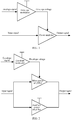
- a phase of a Doherty power amplifier is not optimal at different envelope voltages. Consequently, this manner has a relatively poor power amplifier effect and poor power amplifier performance.
- the existing high-efficiency power amplifier technology has problems such as a relatively poor effect and poor performance. Therefore, a new power amplifier technology is urgently needed to resolve the foregoing problems.
- US 2010/128 775 A1 discloses an apparatus and method for transmitting a signal in a wireless communication system. Based on power control information of a baseband signal, a phase signal and an envelope signal are generated. A phase modulator up-converts the phase signal. An amplifier combines the envelope signal and the up-converted phase signal, and the combined signal is amplified.
- CN 1 866 733 A1 discloses a Doherty power amplifier device with a phase adjusting unit that adjusts the amplitudes and phases of the signals routed through a carrier power amplifier and a crest value power amplifier, so as to improve the flexibility of the amplifier.
- Embodiments of the present invention provide a power amplifier control method and apparatus, and a power amplifier control system, to resolve problems such as a relatively poor effect and poor performance that exist in an existing high-efficiency power amplifier technology.
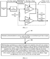
- a power amplifier control method is provided, and is applicable to a power amplifier system that includes an envelope control circuit and a Doherty power amplifier circuit, where the envelope control circuit includes an envelope modulator configured to: generate an envelope voltage according to an envelope signal that is output by a baseband unit, and output the envelope voltage to the Doherty power amplifier circuit as a supply voltage; the Doherty power amplifier circuit includes a main power amplifier and an auxiliary power amplifier; the main power amplifier and the auxiliary power amplifier are separately configured to perform, according to the envelope voltage that is output by the envelope modulator, amplification processing on a baseband signal that is output by the baseband unit; and the method includes:
- the generating a phase modulation control signal according to the envelope signal that is output by the baseband unit includes:
- the performing phase modulation on a signal of a main power amplifier link and/or an auxiliary power amplifier link in the Doherty power amplifier circuit according to the generated phase modulation control signal includes:
- the performing phase modulation on a signal of an auxiliary power amplifier link in the Doherty power amplifier circuit includes: performing phase modulation on a signal of each auxiliary power amplifier link in the Doherty power amplifier circuit.
- the envelope control circuit includes one envelope modulator separately connected to power amplifiers in the Doherty power amplifier circuit, where the one envelope modulator is configured to output an envelope voltage to the power amplifiers in the Doherty power amplifier circuit; or includes a plurality of envelope modulators connected to power amplifiers in the Doherty power amplifier circuit in a one-to-one corresponding manner, where each of the plurality of envelope modulators is configured to output an envelope voltage to a corresponding power amplifier in the Doherty power amplifier circuit.
- the phase modulation is digital phase modulation or analog phase modulation.
- a power amplifier control apparatus is provided, and is applicable to a power amplifier system that includes an envelope control circuit and a Doherty power amplifier circuit, where the envelope control circuit includes an envelope modulator configured to: generate an envelope voltage according to an envelope signal that is output by a baseband unit, and output the envelope voltage to the Doherty power amplifier circuit as a supply voltage; the Doherty power amplifier circuit includes a main power amplifier and an auxiliary power amplifier; the main power amplifier and the auxiliary power amplifier are separately configured to perform, according to the envelope voltage that is output by the envelope modulator, amplification processing on a baseband signal that is output by the baseband unit; and the apparatus includes:
- the signal generation unit is specifically configured to: if it is determined that the current value of the envelope signal is not greater than a specified envelope opening threshold, generate a first phase modulation control signal according to the envelope signal, where the first phase modulation control signal enables the phase difference between the signal of the main power amplifier link and the signal of the auxiliary power amplifier link after the phase modulation to be a first phase value; and the first phase value is an optimal phase value of the Doherty power amplifier circuit in the state where the supply voltage of the Doherty power amplifier circuit is a minimum envelope voltage; or if it is determined that the current value of the envelope signal is a specified envelope signal maximum value, generate a second phase modulation control signal according to the envelope signal, where the second phase modulation control signal enables the phase difference between the signal of the main power amplifier link and the signal of the auxiliary power amplifier link after the phase modulation to be a second phase value; the second phase value is an optimal phase value of the Doherty power amplifier circuit in the state where the supply voltage of the Doherty power amplifier circuit is
- the signal phase modulation unit is specifically configured to: after performing frequency conversion processing on a baseband signal corresponding to the main power amplifier link and/or the auxiliary power amplifier link in the Doherty power amplifier circuit, perform the phase modulation on the signal of the main power amplifier link and/or the auxiliary power amplifier link in the Doherty power amplifier circuit; or before performing frequency conversion processing on a baseband signal corresponding to the main power amplifier link and/or the auxiliary power amplifier link in the Doherty power amplifier circuit, perform the phase modulation on the signal of the main power amplifier link and/or the auxiliary power amplifier link in the Doherty power amplifier circuit.
- the signal phase modulation unit is specifically configured to: when there are a plurality of auxiliary power amplifiers in the Doherty power amplifier circuit, and phase modulation needs to be performed on signals of the auxiliary power amplifier links in the Doherty power amplifier circuit, perform phase modulation on a signal of each auxiliary power amplifier link in the Doherty power amplifier circuit.
- the envelope control circuit includes one envelope modulator separately connected to power amplifiers in the Doherty power amplifier circuit, where the one envelope modulator is configured to output an envelope voltage to the power amplifiers in the Doherty power amplifier circuit; or includes a plurality of envelope modulators connected to power amplifiers in the Doherty power amplifier circuit in a one-to-one corresponding manner, where each of the plurality of envelope modulators is configured to output an envelope voltage to a corresponding power amplifier in the Doherty power amplifier circuit.
- the phase modulation is digital phase modulation or analog phase modulation.
- a power amplifier control apparatus is provided, and is applicable to a power amplifier system that includes an envelope control circuit and a Doherty power amplifier circuit, where the envelope control circuit includes an envelope modulator configured to: generate an envelope voltage according to an envelope signal that is output by a baseband unit, and output the envelope voltage to the Doherty power amplifier circuit as a supply voltage; the Doherty power amplifier circuit includes a main power amplifier and an auxiliary power amplifier; the main power amplifier and the auxiliary power amplifier are separately configured to perform, according to the envelope voltage that is output by the envelope modulator, amplification processing on a baseband signal that is output by the baseband unit; and the apparatus includes:
- the signal generator is specifically configured to: if it is determined that the current value of the envelope signal is not greater than a specified envelope opening threshold, generate a first phase modulation control signal according to the envelope signal, where the first phase modulation control signal can enable the phase difference between the signal of the main power amplifier link and the signal of the auxiliary power amplifier link after the phase modulation to be a first phase value; and the first phase value is an optimal phase value of the Doherty power amplifier circuit when the supply voltage of the Doherty power amplifier circuit is a minimum envelope voltage; or if it is determined that the current value of the envelope signal is a specified envelope signal maximum value, generate a second phase modulation control signal according to the envelope signal, where the second phase modulation control signal can enable the phase difference between the signal of the main power amplifier link and the signal of the auxiliary power amplifier link after the phase modulation to be a second phase value; the second phase value is an optimal phase value of the Doherty
- the signal modulator is specifically configured to: after performing frequency conversion processing on a baseband signal corresponding to the main power amplifier link and/or the auxiliary power amplifier link in the Doherty power amplifier circuit, perform the phase modulation on the signal of the main power amplifier link and/or the auxiliary power amplifier link in the Doherty power amplifier circuit; or before performing frequency conversion processing on a baseband signal corresponding to the main power amplifier link and/or the auxiliary power amplifier link in the Doherty power amplifier circuit, perform the phase modulation on the signal of the main power amplifier link and/or the auxiliary power amplifier link in the Doherty power amplifier circuit.
- auxiliary power amplifiers in the Doherty power amplifier circuit there is one or more auxiliary power amplifiers in the Doherty power amplifier circuit; and the signal modulator is specifically configured to: when there are a plurality of auxiliary power amplifiers in the Doherty power amplifier circuit, and phase modulation needs to be performed on signals of the auxiliary power amplifier links in the Doherty power amplifier circuit, perform phase modulation on a signal of each auxiliary power amplifier link in the Doherty power amplifier circuit.
- the envelope control circuit includes one envelope modulator separately connected to power amplifiers in the Doherty power amplifier circuit, where the one envelope modulator is configured to output an envelope voltage to the power amplifiers in the Doherty power amplifier circuit; or includes a plurality of envelope modulators connected to power amplifiers in the Doherty power amplifier circuit in a one-to-one corresponding manner, where each of the plurality of envelope modulators is configured to output an envelope voltage to a corresponding power amplifier in the Doherty power amplifier circuit.
- the phase modulation is digital phase modulation or analog phase modulation.
- a power amplifier control system including a power amplifier system that includes an envelope control circuit and a Doherty power amplifier circuit, where the envelope control circuit includes an envelope modulator configured to: generate an envelope voltage according to an envelope signal that is output by a baseband unit, and output the envelope voltage to the Doherty power amplifier circuit as a supply voltage; the Doherty power amplifier circuit includes a main power amplifier and an auxiliary power amplifier; the main power amplifier and the auxiliary power amplifier are separately configured to perform, according to the envelope voltage that is output by the envelope modulator, amplification processing on a baseband signal that is output by the baseband unit; and the power amplifier control system further includes the power amplifier control apparatus according to any one of the second aspect or the first to the fourth possible implementations of the second aspect.
- the phase modulation control signal may be generated according to the envelope signal that is output by the baseband unit; and the phase modulation may be performed on the signal of the main power amplifier link and/or the auxiliary power amplifier link in the Doherty power amplifier circuit according to the phase modulation control signal, so that the phase difference between the signal of the main power amplifier link and the signal of the auxiliary power amplifier link after the phase modulation is the specified value corresponding to the current value of the envelope signal, where the specified value is the optimal phase value of the Doherty power amplifier circuit when the supply voltage of the Doherty power amplifier circuit is the envelope voltage corresponding to the current value of the envelope signal.
- phase compensation may be performed, for different envelope voltages, on the main power amplifier link and/or the auxiliary power amplifier link, so that at the different envelope voltages, the phase difference between the main power amplifier link and the auxiliary power amplifier link in the Doherty power amplifier circuit can be optimized, thereby improving an effect and performance of the power amplifiers.
- FIG. 4 is a schematic flowchart of a power amplifier control method according to Embodiment 1 of the present invention.
- the power amplifier control method is applicable to a power amplifier system that includes an envelope control circuit and a Doherty power amplifier circuit.
- the envelope control circuit includes an envelope modulator configured to: generate an envelope voltage according to an envelope signal that is output by a baseband unit, and output the envelope voltage to the Doherty power amplifier circuit as a supply voltage.
- the Doherty power amplifier circuit includes a main power amplifier and an auxiliary power amplifier.
- the main power amplifier and the auxiliary power amplifier are separately configured to perform, according to the envelope voltage that is output by the envelope modulator, amplification processing on a baseband signal that is output by the baseband unit.
- the control method includes the following steps:
- the phase modulation when the phase modulation is performed on the Doherty power amplifier circuit according to the generated phase modulation control signal, the phase modulation may be performed only on the signal of the main power amplifier link, and a phase of the signal of the auxiliary power amplifier link remains unchanged; or the phase modulation may be performed only on the signal of the auxiliary power amplifier link, and a phase of the signal of the main power amplifier link remains unchanged; or the phase modulation may be performed on both the signal of the main power amplifier link and the signal of the auxiliary power amplifier link.
- a power amplifier link that requires the phase modulation may be selected according to an actual requirement, as long as it is ensured that the phase difference between the signal of the Doherty main power amplifier link and the signal of the Doherty auxiliary power amplifier link reaches a required value. Details are not described.
- the phase modulation may be performed on the signal of the main power amplifier link and/or the auxiliary power amplifier link in the Doherty power amplifier circuit by using the generated phase modulation control signal, so that the phase difference between the signal of the main power amplifier link in the Doherty power amplifier circuit and the signal of the auxiliary power amplifier link in the Doherty power amplifier circuit reaches an optimal phase of the Doherty power amplifier circuit at an envelope voltage value corresponding to the current envelope signal.
- phase compensation may be performed, for different envelope voltages, on the main power amplifier link and/or the auxiliary power amplifier link, so that at the different envelope voltages, the phase difference between the main power amplifier link and the auxiliary power amplifier link can each reach a corresponding optimal value, thereby improving an effect and performance of a power amplifier, and resolving problems such as a relatively poor effect and poor performance that exist in an existing high-efficiency power amplifier technology.
- the generating a phase modulation control signal according to the envelope signal that is output by the baseband unit in step 401 includes:
- the first phase value is the optimal phase value of the Doherty power amplifier circuit when the envelope voltage is minimum, because when the current value of the envelope signal is not greater than the specified envelope opening threshold (the threshold may be flexibly adjusted according to an actual status), the power amplifier system operates in a pure Doherty state, and the envelope modulator outputs a fixed voltage VDDL (that is, the minimum envelope voltage) to the drains of power amplifiers in the Doherty power amplifier circuit.
- VDDL that is, the minimum envelope voltage
- the second phase value is the optimal phase value of the Doherty power amplifier circuit when the envelope voltage is maximum, because when the envelope signal is greater than the specified envelope opening threshold, the power amplifier system operates in a state of Doherty and ET at the same moment, an output voltage of the envelope modulator changes according to an envelope of the envelope signal.
- the envelope signal reaches a maximum value, that is, reaches the specified envelope signal maximum value, and the envelope modulator outputs a maximum output voltage VDDH (that is, the maximum envelope voltage) to the drains of power amplifiers in the Doherty power amplifier circuit. Details are not described herein.
- the generated phase modulation control signal may be specifically a voltage signal.
- the Doherty power amplifier circuit includes one main power amplifier and one auxiliary power amplifier, and the phase modulation needs to be performed on the signal of the auxiliary power amplifier link in the Doherty power amplifier circuit, and then:
- the performing phase modulation on a signal of a main power amplifier link and/or an auxiliary power amplifier link in the Doherty power amplifier circuit according to the generated phase modulation control signal in step 402 includes:
- a phase modulation operation may be performed after the frequency conversion or before the frequency conversion. This is not limited in this embodiment of the present invention.
- the frequency conversion processing may be performed, on an up-conversion device, on the baseband signal generated by the baseband unit, to obtain a plurality of radio frequency signals in a one-to-one correspondence to the power amplifiers in the Doherty power amplifier circuit, and then phase modulation may be performed on a radio frequency signal corresponding to the auxiliary power amplifier link; in this case, to simplify a system structure, and reduce a quantity of up-conversion devices, the baseband unit may output only one baseband signal to the power amplifier system, or certainly may output a plurality of baseband signals in a one-to-one correspondence to the power amplifiers in the Doherty power amplifier circuit, and this is not limited herein; or before the frequency conversion processing is performed, on an up-conversion device, on the baseband signal generated by the baseband unit, phase modulation may be performed on the baseband signal that is generated by the baseband unit and that
- the performing phase modulation on a signal of an auxiliary power amplifier link in the Doherty power amplifier circuit includes: performing phase modulation on a signal of each auxiliary power amplifier link in the Doherty power amplifier circuit.
- the Doherty power amplifier circuit includes one main power amplifier and N (a value of N is a positive integer greater than 1) auxiliary power amplifiers; if phase modulation needs to be performed on both a signal of a main power amplifier link in the Doherty power amplifier circuit and signals of auxiliary power amplifier links in the Doherty power amplifier circuit, the phase modulation is performed on the signal of the main power amplifier link, and the phase modulation is performed on a signal of each auxiliary power amplifier link, so that after the phase modulation, a phase difference between the signal of the main power amplifier link and the signal of each auxiliary power amplifier link is a specified value corresponding to the current value of the envelope signal. Details are not described herein.
- auxiliary power amplifiers in the Doherty power amplifier circuit indicate higher output power of the Doherty power amplifier circuit. Therefore, in an actual application, a Doherty power amplifier circuit (that is, a multilevel Doherty power amplifier circuit) having a plurality of auxiliary power amplifiers may be used according to an actual requirement to meet a high requirement on power. This is not described in detail in this embodiment of the present invention.
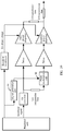
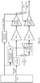
- envelope modulators there is one or more envelope modulators in the envelope control circuit; when there is one envelope modulator in the envelope control circuit, the envelope modulator may be separately connected to power amplifiers in the Doherty power amplifier circuit, to output an envelope voltage to the power amplifiers in the Doherty power amplifier circuit; details may be shown in FIG. 6 and FIG. 7 ; or when there are a plurality of envelope modulators in the envelope control circuit, for example, when the envelope control circuit includes a plurality of envelope modulators connected to the power amplifiers in the Doherty power amplifier circuit in a one-to-one corresponding manner, each of the plurality of envelope modulators may be configured to output an envelope voltage to a corresponding power amplifier in the Doherty power amplifier circuit; detail may be shown in FIG. 8 .
- each of the plurality of envelope modulators may correspond to a unique power amplifier, and may further correspond to a plurality of power amplifiers. Details are not described herein.
- the Doherty power amplifier circuit in this embodiment of the present invention may include a main power amplifier and an auxiliary power amplifier, and may further include a drive power amplifier configured to provide a drive signal to power amplifiers, and a related device such as a quarter-wave transmission line. Details are not described herein.
- phase modulation is digital phase modulation or analog phase modulation.
- the digital phase modulation may include QPSK (quadrature phase shift keying), or the like
- the analog phase modulation may include loop parameter phase shift, RC network phase shift, variable delay method phase modulation, and the like. This is not described in detail herein again.
- phase modulation manner may be flexibly selected according to an actual requirement, to further improve flexibility of power amplifier control.
- Embodiment 1 of the present invention provides the power amplifier control method, applicable to the power amplifier system that includes the envelope control circuit and the Doherty power amplifier circuit.
- the phase modulation control signal may be generated according to the envelope signal that is output by the baseband unit; and the phase modulation may be performed on the signal of the main power amplifier link and/or the auxiliary power amplifier link in the Doherty power amplifier circuit according to the phase modulation control signal, so that the phase difference between the signal of the main power amplifier link and the signal of the auxiliary power amplifier link after the phase modulation is the specified value corresponding to the current value of the envelope signal, where the specified value is the optimal phase value of the Doherty power amplifier circuit when the supply voltage of the Doherty power amplifier circuit is the envelope voltage corresponding to the current value of the envelope signal.
- phase compensation may be performed, for different envelope voltages, on the main power amplifier link and/or the auxiliary power amplifier link, so that at the different envelope voltages, the phase difference between the main power amplifier link and the auxiliary power amplifier link can each reach an optimal value. Therefore, on a basis that an advantage of back-off efficiency of the Doherty power amplifier is fully used and saturation power of a power amplifier is increased by using an ET function, performance of the power amplifier can be further improved by adjusting phases at different voltages, thereby resolving problems such as a relatively poor effect and poor performance that exist in an existing high-efficiency power amplifier technology.
- Embodiment 2 of the present invention provides a power amplifier control apparatus, applicable to a power amplifier system that includes an envelope control circuit and a Doherty power amplifier circuit.
- the envelope control circuit includes an envelope modulator configured to: generate an envelope voltage according to an envelope signal that is output by a baseband unit, and output the envelope voltage to the Doherty power amplifier circuit as a supply voltage.
- the Doherty power amplifier circuit includes a main power amplifier and an auxiliary power amplifier. The main power amplifier and the auxiliary power amplifier are separately configured to perform, according to the envelope voltage that is output by the envelope modulator, amplification processing on a baseband signal that is output by the baseband unit.
- the apparatus may include:
- the signal generation unit 91 may generate a phase modulation control signal, and output the phase modulation control signal to the signal phase modulation unit 92, so as to perform the phase modulation on the signal of the main power amplifier link and/or the auxiliary power amplifier link in the Doherty power amplifier circuit, so that the phase difference between the signal of the main power amplifier link in the Doherty power amplifier circuit and the signal of the auxiliary power amplifier link in the Doherty power amplifier circuit reaches an optimal phase of the Doherty power amplifier circuit at an envelope voltage value corresponding to the current envelope signal.
- phase compensation may be performed, for different envelope voltages, on the main power amplifier link and/or the auxiliary power amplifier link, so that at the different envelope voltages, the phase difference between the main power amplifier link and the auxiliary power amplifier link can each reach a corresponding optimal value, thereby improving an effect and performance of a power amplifier, and resolving problems such as a relatively poor effect and poor performance that exist in an existing high-efficiency power amplifier technology.
- the signal generation unit 91 is specifically configured to: if it is determined that the current value of the envelope signal is not greater than a specified envelope opening threshold, generate a first phase modulation control signal according to the envelope signal, where the first phase modulation control signal can enable the phase difference between the signal of the main power amplifier link and the signal of the auxiliary power amplifier link after the phase modulation to be a first phase value; and the first phase value is an optimal phase value of the Doherty power amplifier circuit when the supply voltage of the Doherty power amplifier circuit is a minimum envelope voltage; or if it is determined that the current value of the envelope signal is a specified envelope signal maximum value, generate a second phase modulation control signal according to the envelope signal, where the second phase modulation control signal can enable the phase difference between the signal of the main power amplifier link and the signal of the auxiliary power amplifier link after the phase modulation to be a second phase value; the second phase value is an optimal phase value of the Doherty power amplifier circuit when the supply voltage of the Doherty power amplifier circuit is a maximum
- the signal generation unit 91 may generate a phase modulation control signal that enables the phase difference between the signal of the main power amplifier link and the signal of the auxiliary power amplifier link to linearly change according to the envelope signal.
- the first phase value is the optimal phase value of the Doherty power amplifier circuit when the envelope voltage is minimum, because when the current value of the envelope signal is not greater than the specified envelope opening threshold (the threshold may be flexibly adjusted according to an actual status), the power amplifier system operates in a pure Doherty state, and the envelope modulator outputs a fixed voltage VDDL (that is, the minimum envelope voltage) to the drains of power amplifiers in the Doherty power amplifier circuit.
- VDDL that is, the minimum envelope voltage
- the second phase value is the optimal phase value of the Doherty power amplifier circuit when the envelope voltage is maximum, because when the envelope signal is greater than the specified envelope opening threshold, the power amplifier system operates in a common state of Doherty and ET, an output voltage of the envelope modulator changes according to an envelope of the envelope signal.
- the envelope signal reaches a maximum value, that is, reaches the specified envelope signal maximum value, and the envelope modulator outputs a maximum output voltage VDDH (that is, the maximum envelope voltage) to the drains of power amplifiers in the Doherty power amplifier circuit. Details are not described herein.
- the signal phase modulation unit 92 is specifically configured to: after performing frequency conversion processing on a baseband signal corresponding to the main power amplifier link and/or the auxiliary power amplifier link in the Doherty power amplifier circuit, perform the phase modulation on the signal of the main power amplifier link and/or the auxiliary power amplifier link in the Doherty power amplifier circuit; or before performing frequency conversion processing on a baseband signal corresponding to the main power amplifier link and/or the auxiliary power amplifier link in the Doherty power amplifier circuit, perform the phase modulation on the signal of the main power amplifier link and/or the auxiliary power amplifier link in the Doherty power amplifier circuit.
- a phase modulation operation may be performed after the frequency conversion or before the frequency conversion. This is not limited in this embodiment of the present invention.
- the frequency conversion processing may be performed, on an up-conversion device, on the baseband signal generated by the baseband unit, to obtain a plurality of radio frequency signals in a one-to-one correspondence to the power amplifiers in the Doherty power amplifier circuit, and then phase modulation may be performed on a radio frequency signal corresponding to the auxiliary power amplifier link, in this case, to simplify a system structure, and reduce a quantity of up-conversion devices, the baseband unit may output only one baseband signal to the power amplifier system, or certainly may output a plurality of baseband signals in a one-to-one correspondence to the power amplifiers in the Doherty power amplifier circuit, and this is not limited herein; or as shown in FIG.
- phase modulation may be performed on the baseband signal that is generated by the baseband unit and that needs to be input to the auxiliary power amplifier link in the Doherty power amplifier circuit; in this case, the baseband unit may output a plurality of baseband signals in a one-to-one correspondence to the power amplifiers in the Doherty power amplifier circuit, or may output only two baseband signals, where one baseband signal corresponds to the main power amplifier link and the other baseband signal corresponds to all auxiliary power amplifier links; in addition, it should be noted that, phase modulation on a baseband signal corresponding to the auxiliary power amplifier link may be completed in a process of generating, by the baseband unit, the corresponding baseband signal (that is, in this case, the power amplifier control apparatus may be equivalent to being integrated into the baseband unit, and exists as a subunit of the baseband unit), or may be completed after the baseband unit generates the corresponding
- auxiliary power amplifiers in the Doherty power amplifier circuit
- the signal phase modulation unit 92 is specifically configured to: when there are a plurality of auxiliary power amplifiers in the Doherty power amplifier circuit, and phase modulation needs to be performed on signals of the auxiliary power amplifier links in the Doherty power amplifier circuit, perform phase modulation on a signal of each auxiliary power amplifier link in the Doherty power amplifier circuit.
- the Doherty power amplifier circuit includes one main power amplifier and N (a value of N is a positive integer greater than 1) auxiliary power amplifiers; if phase modulation needs to be performed on both a signal of a main power amplifier link in the Doherty power amplifier circuit and signals of auxiliary power amplifier links in the Doherty power amplifier circuit, the phase modulation is performed on the signal of the main power amplifier link, and the phase modulation is performed on a signal of each auxiliary power amplifier link, so that after the phase modulation, a phase difference between the signal of the main power amplifier link and the signal of each auxiliary power amplifier link is a specified value corresponding to the current value of the envelope signal. Details are not described herein.
- auxiliary power amplifiers in the Doherty power amplifier circuit indicate higher output power of the Doherty power amplifier circuit. Therefore, in an actual application, a Doherty power amplifier circuit (that is, a multilevel Doherty power amplifier circuit) having a plurality of auxiliary power amplifiers may be used according to an actual requirement to meet a high requirement on power. This is not described in detail in this embodiment of the present invention.
- the signal generation unit 91 may include one or more small signal modulators; and the signal phase modulation unit 92 may include one or more phase modulation circuits.
- the signal generation unit 91 may include one small signal modulator, and the signal phase modulation unit 92 may include one phase modulation circuit corresponding to the small signal modulator;
- the small signal modulator is configured to: generate a phase modulation control signal according to an envelope signal generated by the baseband unit, and output the phase modulation control signal to the phase modulation circuit;
- the phase modulation circuit is configured to adjust a phase of a corresponding power amplifier link to a specified phase according to the phase modulation control signal that is output by the small signal modulator; or when phase modulation needs to be performed on both a signal of a main power amplifier link and a signal of an auxiliary power amplifier link, as shown in FIG.
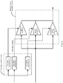
- the signal generation unit 91 may include one first small signal modulator configured to generate a first sub-phase modulation control signal corresponding to the main power amplifier link, and one second small signal modulator configured to generate a second sub-phase modulation control signal corresponding to the auxiliary power amplifier link; and the signal phase modulation unit 92 may include a first phase modulation circuit that corresponds to the first small signal modulator and that is configured to adjust a phase of a signal corresponding to the main power amplifier link to a first sub-phase, and a second phase modulation circuit that corresponds to the second small signal modulator and that is configured to adjust a phase of a signal corresponding to the auxiliary power amplifier link to a second sub-phase, where a phase difference between the first sub-phase and the second sub-phase is a specified value.
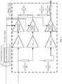
- the signal generation unit 91 may include a plurality of small signal modulators (for example, a small signal modulator 1 to a small signal modulator N shown in FIG. 14 ) that each are in a one-to-one correspondence to the plurality of auxiliary power amplifiers
- the signal phase modulation unit 92 may include a plurality of phase modulation circuits (for example, a phase modulation circuit 1 to a phase modulation circuit N shown in FIG. 14 ) that each are in a one-to-one correspondence to the plurality of auxiliary power amplifiers. Details are not described herein.
- both a quantity of small signal modulators in the signal generation unit 91 and a quantity of phase modulation circuits in the signal phase modulation unit 92 may be flexibly set according to an actual status, as long as it can be ensured that a phase difference between a signal of a main power amplifier link in the Doherty power amplifier circuit and a signal of an auxiliary power amplifier link in the Doherty power amplifier circuit is a specified value. This is not described in detail.
- envelope modulators there is one or more envelope modulators in the envelope control circuit; when there is one envelope modulator in the envelope control circuit, the envelope modulator may be separately connected to power amplifiers in the Doherty power amplifier circuit, to output an envelope voltage to the power amplifiers in the Doherty power amplifier circuit; details may be shown in FIG. 7 ; or when there are a plurality of envelope modulators in the envelope control circuit, for example, when the envelope control circuit includes a plurality of envelope modulators connected to the power amplifiers in the Doherty power amplifier circuit in a one-to-one corresponding manner, each of the plurality of envelope modulators may be configured to output an envelope voltage to a corresponding power amplifier in the Doherty power amplifier circuit; detail may be shown in FIG. 8 .
- each of the plurality of envelope modulators may correspond to a unique power amplifier, and may further correspond to a plurality of power amplifiers. Details are not described herein.
- phase modulation is digital phase modulation or analog phase modulation.
- the digital phase modulation may include QPSK (quadrature phase shift keying), or the like
- the analog phase modulation may include loop parameter phase shift, RC network phase shift, variable delay method phase modulation, and the like. This is not described in detail herein again.
- a modulation manner may be flexibly selected according to an actual requirement, to further improve flexibility of power amplifier control.
- the power amplifier control apparatus in this embodiment of the present invention may exist independently of a device such as the baseband unit.
- the power amplifier control apparatus may exist independently of the device such as the baseband unit, the power amplifier control apparatus may be further integrated into the baseband unit and exist as a subunit of the baseband unit, as shown in FIG. 11 . This is not described in detail.
- Embodiment 3 of the present invention further provides another power amplifier control apparatus, applicable to a power amplifier system that includes an envelope control circuit and a Doherty power amplifier circuit.
- the envelope control circuit includes an envelope modulator configured to: generate an envelope voltage according to an envelope signal that is output by a baseband unit, and output the envelope voltage to the Doherty power amplifier circuit as a supply voltage.
- the Doherty power amplifier circuit includes a main power amplifier and an auxiliary power amplifier. The main power amplifier and the auxiliary power amplifier are separately configured to perform, according to the envelope voltage that is output by the envelope modulator, amplification processing on a baseband signal that is output by the baseband unit.
- the apparatus may include:
- the signal generator 151 may generate a phase modulation control signal, and output the phase modulation control signal to the signal modulator 152, so as to perform the phase modulation on the signal of the main power amplifier link and/or the auxiliary power amplifier link in the Doherty power amplifier circuit, so that the phase difference between the signal of the main power amplifier link in the Doherty power amplifier circuit and the signal of the auxiliary power amplifier link in the Doherty power amplifier circuit reaches an optimal phase of the Doherty power amplifier circuit at an envelope voltage value corresponding to the current envelope signal.
- phase compensation may be performed, for different envelope voltages, on the main power amplifier link and/or the auxiliary power amplifier link, so that at the different envelope voltages, the phase difference between the main power amplifier link and the auxiliary power amplifier link can each reach a corresponding optimal value, thereby improving an effect and performance of a power amplifier, and resolving problems such as a relatively poor effect and poor performance that exist in an existing high-efficiency power amplifier technology.
- the signal generator 151 is specifically configured to: if it is determined that the current value of the envelope signal is not greater than a specified envelope opening threshold, generate a first phase modulation control signal according to the envelope signal, where the first phase modulation control signal can enable the phase difference between the signal of the main power amplifier link and the signal of the auxiliary power amplifier link after the phase modulation to be a first phase value; and the first phase value is an optimal phase value of the Doherty power amplifier circuit when the supply voltage of the Doherty power amplifier circuit is a minimum envelope voltage; or if it is determined that the current value of the envelope signal is a specified envelope signal maximum value, generate a second phase modulation control signal according to the envelope signal, where the second phase modulation control signal can enable the phase difference between the signal of the main power amplifier link and the signal of the auxiliary power amplifier link after the phase modulation to be a second phase value; the second phase value is an optimal phase value of the Doherty power amplifier circuit when the supply voltage of the Doherty power amplifier circuit is a maximum envelope
- the signal generator 151 may generate a phase modulation control signal that enables the phase difference between the signal of the main power amplifier link and the signal of the auxiliary power amplifier link to linearly change according to the envelope signal.
- the first phase value is the optimal phase value of the Doherty power amplifier circuit when the envelope voltage is minimum, because when the current value of the envelope signal is not greater than the specified envelope opening threshold (the threshold may be flexibly adjusted according to an actual status), the power amplifier system operates in a pure Doherty state, and the envelope modulator outputs a fixed voltage VDDL (that is, the minimum envelope voltage) to the drains of power amplifiers in the Doherty power amplifier circuit.
- VDDL that is, the minimum envelope voltage
- the second phase value is the optimal phase value of the Doherty power amplifier circuit when the envelope voltage is maximum, because when the envelope signal is greater than the specified envelope opening threshold, the power amplifier system operates in a common state of Doherty and ET, an output voltage of the envelope modulator changes according to an envelope of the envelope signal.
- the envelope signal reaches a maximum value, that is, reaches the specified envelope signal maximum value, and the envelope modulator outputs a maximum output voltage VDDH (that is, the maximum envelope voltage) to the drains of power amplifiers in the Doherty power amplifier circuit. Details are not described herein.
- the signal modulator 152 is specifically configured to: after performing frequency conversion processing on a baseband signal corresponding to the main power amplifier link and/or the auxiliary power amplifier link in the Doherty power amplifier circuit, perform the phase modulation on the signal of the main power amplifier link and/or the auxiliary power amplifier link in the Doherty power amplifier circuit; or before performing frequency conversion processing on a baseband signal corresponding to the main power amplifier link and/or the auxiliary power amplifier link in the Doherty power amplifier circuit, perform the phase modulation on the signal of the main power amplifier link and/or the auxiliary power amplifier link in the Doherty power amplifier circuit.
- a phase modulation operation may be performed after the frequency conversion or before the frequency conversion. This is not limited in this embodiment of the present invention.
- the frequency conversion processing may be performed, on an up-conversion device, on the baseband signal generated by the baseband unit, to obtain a plurality of radio frequency signals in a one-to-one correspondence to the power amplifiers in the Doherty power amplifier circuit, and then phase modulation may be performed on a radio frequency signal corresponding to the auxiliary power amplifier link; in this case, to simplify a system structure, and reduce a quantity of up-conversion devices, the baseband unit may output only one baseband signal to the power amplifier system, or certainly may output a plurality of baseband signals in a one-to-one correspondence to the power amplifiers in the Doherty power amplifier circuit, and this is not limited herein; or before the frequency conversion processing is performed, on an up-conversion device, on the baseband signal generated by the baseband unit, phase modulation may be performed on the baseband signal that is generated by the baseband unit and that
- auxiliary power amplifiers in the Doherty power amplifier circuit
- the signal modulator 152 is specifically configured to: when there are a plurality of auxiliary power amplifiers in the Doherty power amplifier circuit, and phase modulation needs to be performed on signals of the auxiliary power amplifier links in the Doherty power amplifier circuit, perform phase modulation on a signal of each auxiliary power amplifier link in the Doherty power amplifier circuit.
- the Doherty power amplifier circuit includes one main power amplifier and N (a value of N is a positive integer greater than 1) auxiliary power amplifiers; if phase modulation needs to be performed on both a signal of a main power amplifier link in the Doherty power amplifier circuit and signals of auxiliary power amplifier links in the Doherty power amplifier circuit, the phase modulation is performed on the signal of the main power amplifier link, and the phase modulation is performed on a signal of each auxiliary power amplifier link, so that after the phase modulation, a phase difference between the signal of the main power amplifier link and the signal of each auxiliary power amplifier link is a specified value corresponding to the current value of the envelope signal. Details are not described herein.
- auxiliary power amplifiers in the Doherty power amplifier circuit indicate higher output power of the Doherty power amplifier circuit. Therefore, in an actual application, a Doherty power amplifier circuit (that is, a multilevel Doherty power amplifier circuit) having a plurality of auxiliary power amplifiers may be used according to an actual requirement to meet a high requirement on power. This is not described in detail in this embodiment of the present invention.
- the signal generator 151 may include one or more small signal modulators; and the signal modulator 152 may include one or more phase modulation circuits.
- the signal generator 151 may include one small signal modulator, and the signal modulator 152 may include one phase modulation circuit corresponding to the small signal modulator; the small signal modulator is configured to: generate a phase modulation control signal according to an envelope signal generated by the baseband unit, and output the phase modulation control signal to the phase modulation circuit; and the phase modulation circuit is configured to adjust a phase of a corresponding power amplifier link to a specified phase according to the phase modulation control signal that is output by the small signal modulator; or when phase modulation needs to be performed on both a signal of a main power amplifier link and a signal of an auxiliary power amplifier link, the signal generator 151 may include one first small signal modulator configured to generate a first sub-phase modulation control signal corresponding to the main power amplifier link, and one second small signal modulator configured to generate a second sub-phase modul
- the signal generator 151 may include a plurality of small signal modulators that each are in a one-to-one correspondence to the plurality of auxiliary power amplifiers
- the signal modulator 152 may include a plurality of phase modulation circuits that each are in a one-to-one correspondence to the plurality of auxiliary power amplifiers. Details are not described herein.
- both a quantity of small signal modulators in the signal generator 151 and a quantity of phase modulation circuits in the signal modulator 152 may be flexibly set according to an actual status, as long as it can be ensured that a phase difference between a signal of a main power amplifier link in the Doherty power amplifier circuit and a signal of an auxiliary power amplifier link in the Doherty power amplifier circuit is a specified value. This is not described in detail.
- envelope modulators there is one or more envelope modulators in the envelope control circuit; when there is one envelope modulator in the envelope control circuit, the envelope modulator may be separately connected to power amplifiers in the Doherty power amplifier circuit, to output an envelope voltage to the power amplifiers in the Doherty power amplifier circuit; details may be shown in FIG. 7 ; or when there are a plurality of envelope modulators in the envelope control circuit, for example, when the envelope control circuit includes a plurality of envelope modulators connected to the power amplifiers in the Doherty power amplifier circuit in a one-to-one corresponding manner, each of the plurality of envelope modulators may be configured to output an envelope voltage to a corresponding power amplifier in the Doherty power amplifier circuit; detail may be shown in FIG. 8 .
- each of the plurality of envelope modulators may correspond to a unique power amplifier, and may further correspond to a plurality of power amplifiers. Details are not described herein.
- phase modulation is digital phase modulation or analog phase modulation.
- the digital phase modulation may include QPSK (Quadrature Phase Shift Keying, quadrature phase shift keying), or the like
- the analog phase modulation may include loop parameter phase shift, RC network phase shift, variable delay method phase modulation, and the like. This is not described in detail herein again.
- a modulation manner may be flexibly selected according to an actual requirement, to further improve flexibility of power amplifier control.
- the power amplifier control apparatus in this embodiment of the present invention may exist independently of a device such as the baseband unit.
- the power amplifier control apparatus may exist independently of the device such as the baseband unit, the power amplifier control apparatus may be further integrated into the baseband unit and exist as a subunit of the baseband unit. This is not described in detail.
- Embodiment 4 of the present invention provides a power amplifier control system, including a power amplifier system that includes an envelope control circuit and a Doherty power amplifier circuit.
- the envelope control circuit includes an envelope modulator configured to: generate an envelope voltage according to an envelope signal that is output by a baseband unit, and output the envelope voltage to the Doherty power amplifier circuit as a supply voltage.
- the Doherty power amplifier circuit includes a main power amplifier and an auxiliary power amplifier. The main power amplifier and the auxiliary power amplifier are separately configured to perform, according to the envelope voltage that is output by the envelope modulator, amplification processing on a baseband signal that is output by the baseband unit.
- the power amplifier control system further includes the power amplifier control apparatus in Embodiment 2 of the present invention or the power amplifier control apparatus in Embodiment 3 of the present invention. This is not described in detail.
- the power amplifier control system in this embodiment of the present invention may further include devices, such as the baseband unit configured to generate a baseband signal and a corresponding envelope signal, and an up converter that performs frequency conversion processing on the baseband signal.
- the embodiments of the present invention may be provided as a method, an apparatus (device), or a computer program product. Therefore, the present invention may use a form of hardware only embodiments, software only embodiments, or embodiments with a combination of software and hardware. Moreover, the present invention may use a form of a computer program product that is implemented on one or more computer-usable storage media (including but not limited to a disk memory, a CD-ROM, an optical memory, and the like) that include computer-usable program code.
- computer-usable storage media including but not limited to a disk memory, a CD-ROM, an optical memory, and the like
- These computer program instructions may be provided for a general-purpose computer, a dedicated computer, an embedded processor, or a processor of any other programmable data processing device to generate a machine, so that the instructions executed by a computer or a processor of any other programmable data processing device generate an apparatus for implementing a specific function in one or more processes in the flowcharts and/or in one or more blocks in the block diagrams.
- These computer program instructions may also be stored in a computer readable memory that can instruct the computer or any other programmable data processing device to work in a specific manner, so that the instructions stored in the computer readable memory generate an artifact that includes an instruction apparatus.
- the instruction apparatus implements a specific function in one or more processes in the flowcharts and/or in one or more blocks in the block diagrams.
- These computer program instructions may also be loaded onto a computer or another programmable data processing device, so that a series of operations and steps are performed on the computer or the another programmable device, thereby generating computer-implemented processing. Therefore, the instructions executed on the computer or the another programmable device provide steps for implementing a specific function in one or more processes in the flowcharts and/or in one or more blocks in the block diagrams.
Landscapes
- Engineering & Computer Science (AREA)
- Power Engineering (AREA)
- Physics & Mathematics (AREA)
- Nonlinear Science (AREA)
- Amplifiers (AREA)
Claims (12)
- Leistungsverstärkersteuerverfahren, das auf ein Leistungsverstärkersystem anwendbar ist, das eine Hüllkurvensteuerschaltung und eine Doherty-Leistungsverstärkerschaltung umfasst, wobei die Hüllkurvensteuerschaltung einen Hüllkurvenmodulator umfasst, der zu Folgendem konfiguriert ist:Erzeugen einer Hüllkurvenspannung gemäß einem Hüllkurvensignal, das von einer Basisbandeinheit ausgegeben wird, und Ausgeben der Hüllkurvenspannung an die Doherty-Leistungsverstärkerschaltung als eine Versorgungsspannung;wobei die Doherty-Leistungsverstärkerschaltung einen Hauptleistungsverstärker und einen Hilfsleistungsverstärker umfasst;wobei der Hauptleistungsverstärker und der Hilfsleistungsverstärker getrennt konfiguriert sind, um gemäß der Hüllkurvenspannung, die durch den Hüllkurvenmodulator ausgegeben wird, eine Verstärkungsverarbeitung an einem Basisbandsignal durchzuführen, das durch die Basisbandeinheit ausgegeben wird; undwobei das Verfahren Folgendes umfasst:Erzeugen (401) eines Phasenmodulationssteuersignals gemäß dem Hüllkurvensignal, das durch die Basisbandeinheit ausgegeben wird; undDurchführen (402) einer Phasenmodulation an einem Signal einer Hauptleistungsverstärkerverknüpfung und/oder einer Hilfsleistungsverstärkerverknüpfung in der Doherty-Leistungsverstärkerschaltung gemäß dem erzeugten Phasenmodulationssteuersignal, so dass eine Phasendifferenz zwischen dem Signal der Hauptleistungsverstärkerverknüpfung und dem Signal der Hilfsleistungsverstärkerverknüpfung nach der Phasenmodulation ein spezifizierter Wert ist, der einem aktuellen Wert des Hüllkurvensignals entspricht, wobei der spezifizierte Wert ein optimaler Phasenwert der Doherty-Leistungsverstärkerschaltung in dem Zustand ist, in dem die Versorgungsspannung der Doherty-Leistungsverstärkerschaltung die Hüllkurvenspannung ist, die dem aktuellen Wert des Hüllkurvensignals entspricht, wobei das Erzeugen eines Phasenmodulationssteuersignals gemäß dem Hüllkurvensignal, das von der Basisbandeinheit ausgegeben wird, Folgendes umfasst:falls bestimmt wird, dass der aktuelle Wert des Hüllkurvensignals nicht größer als eine spezifizierte Hüllkurvenöffnungsschwelle ist, Erzeugen eines ersten Phasenmodulationssteuersignals gemäß dem Hüllkurvensignal, wobei das erste Phasenmodulationssteuersignal es der Phasendifferenz zwischen dem Signal der Hauptleistungsverstärkerverknüpfung und dem Signal der Hilfsleistungsverstärkerverknüpfung nach der Phasenmodulation ermöglicht, ein erster Phasenwert zu sein; undwobei der erste Phasenwert ein optimaler Phasenwert der Doherty-Leistungsverstärkerschaltung in dem Zustand ist, in dem die Versorgungsspannung der Doherty-Leistungsverstärkerschaltung eine minimale Hüllkurvenspannung ist; oderfalls bestimmt wird, dass der aktuelle Wert des Hüllkurvensignals ein spezifizierter Hüllkurvensignalmaximalwert ist, Erzeugen eines zweiten Phasenmodulationssteuersignals gemäß dem Hüllkurvensignal, wobei das zweite Phasenmodulationssteuersignal es der Phasendifferenz zwischen dem Signal der Hauptleistungsverstärkerverknüpfung und dem Signal der Hilfsleistungsverstärkerverknüpfung nach der Phasenmodulation ermöglicht, ein zweiter Phasenwert zu sein;wobei der zweite Phasenwert ein optimaler Phasenwert der Doherty-Leistungsverstärkerschaltung in dem Zustand ist, in dem die Versorgungsspannung der Doherty-Leistungsverstärkerschaltung eine maximale Hüllkurvenspannung ist; undwobei der spezifizierte Hüllkurvensignalmaximalwert größer als die spezifizierte Hüllkurvenöffnungsschwelle ist; oderfalls bestimmt wird, dass der aktuelle Wert des Hüllkurvensignals größer als die spezifizierte Hüllkurvenöffnungsschwelle und kleiner als der spezifizierte Hüllkurvensignalmaximalwert ist, Erzeugen eines dritten Phasenmodulationssteuersignals gemäß dem Hüllkurvensignal, wobei das dritte Phasenmodulationssteuersignal es der Phasendifferenz zwischen dem Signal der Hauptleistungsverstärkerverknüpfung und dem Signal der Hilfsleistungsverstärkerverknüpfung nach der Phasenmodulation ermöglicht, ein dritter Phasenwert zu sein;wobei der dritte Phasenwert durch Durchführen einer linearen Interpolationsoperation gemäß dem aktuellen Wert des Hüllkurvensignals, dem ersten Phasenwert, dem zweiten Phasenwert, der Hüllkurvenöffnungsschwelle, die dem ersten Phasenwert entspricht und dem Hüllkurvensignalmaximalwert, der dem zweiten Phasenwert entspricht, erhalten wird.
- Steuerverfahren nach Anspruch 1, wobei das Durchführen der Phasenmodulation an einem Signal einer Hauptleistungsverstärkerverknüpfung und/oder einer Hilfsleistungsverstärkerverknüpfung in der Doherty-Leistungsverstärkerschaltung gemäß dem erzeugten Phasenmodulationssteuersignal Folgendes umfasst:nach dem Durchführen einer Frequenzumwandlungsverarbeitung an einem Basisbandsignal, das der Hauptleistungsverstärkerverknüpfung und/oder der Hilfsleistungsverstärkerverknüpfung in der Doherty-Leistungsverstärkerschaltung entspricht, Durchführen der Phasenmodulation an dem Signal der Hauptleistungsverstärkerverknüpfung und/oder der Hilfsleistungsverstärkerverknüpfung in der Doherty-Leistungsverstärkerschaltung; odervor dem Durchführen einer Frequenzumwandlungsverarbeitung an einem Basisbandsignal, das der Hauptleistungsverstärkerverknüpfung und/oder der Hilfsleistungsverstärkerverknüpfung in der Doherty-Leistungsverstärkerschaltung entspricht, Durchführen der Phasenmodulation an dem Signal der Hauptleistungsverstärkerverknüpfung und/oder der Hilfsleistungsverstärkerverknüpfung in der Doherty-Leistungsverstärkerschaltung.
- Steuerverfahren nach einem der Ansprüche 1 bis 2, wobei mehr als ein Hilfsleistungsverstärker in der Doherty-Leistungsverstärkerschaltung vorhanden ist; und
wenn mehrere Hilfsleistungsverstärker in der Doherty-Leistungsverstärkerschaltung vorhanden sind, das Durchführen einer Phasenmodulation an einem Signal einer Hilfsleistungsverstärkerverknüpfung in der Doherty-Leistungsverstärkerschaltung Folgendes umfasst:
Durchführen einer Phasenmodulation an einem Signal jeder Hilfsleistungsverstärkerverknüpfung in der Doherty-Leistungsverstärkerschaltung. - Steuerverfahren nach einem der Ansprüche 1 bis 3, wobei die Hüllkurvensteuerschaltung einen Hüllkurvenmodulator umfasst, der mit Leistungsverstärkern in der Doherty-Leistungsverstärkerschaltung getrennt verbunden ist, wobei der eine Hüllkurvenmodulator konfiguriert ist, um eine Hüllkurvenspannung an die Leistungsverstärker in der Doherty-Leistungsverstärkerschaltung auszugeben; oder
mehrere Hüllkurvenmodulatoren umfasst, die mit Leistungsverstärkern in der Doherty-Leistungsverstärkerschaltung eins zu eins entsprechend verbunden sind, wobei jeder der mehreren Hüllkurvenmodulatoren konfiguriert ist, um eine Hüllkurvenspannung an einen entsprechenden Leistungsverstärker in der Doherty-Leistungsverstärkerschaltung auszugeben. - Steuerverfahren nach einem der Ansprüche 1 bis 4, wobei die Phasenmodulation eine digitale Phasenmodulation oder eine analoge Phasenmodulation ist.
- Leistungsverstärkersteuereinrichtung, die auf ein Leistungsverstärkersystem anwendbar ist, das eine Hüllkurvensteuerschaltung und eine Doherty-Leistungsverstärkerschaltung umfasst, wobei die Hüllkurvensteuerschaltung einen Hüllkurvenmodulator umfasst, der zu Folgendem konfiguriert ist:Erzeugen einer Hüllkurvenspannung gemäß einem Hüllkurvensignal, das von einer Basisbandeinheit ausgegeben wird, und Ausgeben der Hüllkurvenspannung an die Doherty-Leistungsverstärkerschaltung als eine Versorgungsspannung;wobei die Doherty-Leistungsverstärkerschaltung einen Hauptleistungsverstärker und einen Hilfsleistungsverstärker umfasst;wobei der Hauptleistungsverstärker und der Hilfsleistungsverstärker getrennt konfiguriert sind, um gemäß der Hüllkurvenspannung, die durch den Hüllkurvenmodulator ausgegeben wird, eine Verstärkungsverarbeitung an einem Basisbandsignal durchzuführen, das durch die Basisbandeinheit ausgegeben wird; undwobei die Einrichtung Folgendes umfasst:eine Signalerzeugungseinheit (91, 151), die konfiguriert ist, um ein Phasenmodulationssteuersignal gemäß dem Hüllkurvensignal zu erzeugen, das durch die Basisbandeinheit ausgegeben wird; undeine Signalphasenmodulationseinheit (92, 152), die konfiguriert ist, um die Phasenmodulation an einem Signal einer Hauptleistungsverstärkerverknüpfung und/oder einer Hilfsleistungsverstärkerverknüpfung in der Doherty-Leistungsverstärkerschaltung gemäß dem erzeugten Phasenmodulationssteuersignal durchzuführen, so dass eine Phasendifferenz zwischen dem Signal der Hauptleistungsverstärkerverknüpfung und dem Signal der Hilfsleistungsverstärkerverknüpfung nach der Phasenmodulation ein spezifizierter Wert ist, der einem aktuellen Wert des Hüllkurvensignals entspricht, wobei der spezifizierte Wert ein optimaler Phasenwert der Doherty-Leistungsverstärkerschaltung in dem Zustand ist, in dem die Versorgungsspannung der Doherty-Leistungsverstärkerschaltung die Hüllkurvenspannung ist, die dem aktuellen Wert des Hüllkurvensignals entspricht,wobei die Signalerzeugungseinheit speziell zu Folgendem konfiguriert ist:falls bestimmt wird, dass der aktuelle Wert des Hüllkurvensignals nicht größer als eine spezifizierte Hüllkurvenöffnungsschwelle ist, Erzeugen eines ersten Phasenmodulationssteuersignals gemäß dem Hüllkurvensignal, wobei das erste Phasenmodulationssteuersignal es der Phasendifferenz zwischen dem Signal der Hauptleistungsverstärkerverknüpfung und dem Signal der Hilfsleistungsverstärkerverknüpfung nach der Phasenmodulation ermöglicht, ein erster Phasenwert zu sein; undwobei der erste Phasenwert ein optimaler Phasenwert der Doherty-Leistungsverstärkerschaltung in dem Zustand ist, in dem die Versorgungsspannung der Doherty-Leistungsverstärkerschaltung eine minimale Hüllkurvenspannung ist; oderfalls bestimmt wird, dass der aktuelle Wert des Hüllkurvensignals ein spezifizierter Hüllkurvensignalmaximalwert ist, Erzeugen eines zweiten Phasenmodulationssteuersignals gemäß dem Hüllkurvensignal, wobei das zweite Phasenmodulationssteuersignal es der Phasendifferenz zwischen dem Signal der Hauptleistungsverstärkerverknüpfung und dem Signal der Hilfsleistungsverstärkerverknüpfung nach der Phasenmodulation ermöglicht, ein zweiter Phasenwert zu sein;wobei der zweite Phasenwert ein optimaler Phasenwert der Doherty-Leistungsverstärkerschaltung in dem Zustand ist, in dem die Versorgungsspannung der Doherty-Leistungsverstärkerschaltung eine maximale Hüllkurvenspannung ist; undwobei der spezifizierte Hüllkurvensignalmaximalwert größer als die spezifizierte Hüllkurvenöffnungsschwelle ist; oderfalls bestimmt wird, dass der aktuelle Wert des Hüllkurvensignals größer als die spezifizierte Hüllkurvenöffnungsschwelle und kleiner als der spezifizierte Hüllkurvensignalmaximalwert ist, Erzeugen eines dritten Phasenmodulationssteuersignals gemäß dem Hüllkurvensignal, wobei das dritte Phasenmodulationssteuersignal es der Phasendifferenz zwischen dem Signal der Hauptleistungsverstärkerverknüpfung und dem Signal der Hilfsleistungsverstärkerverknüpfung nach der Phasenmodulation ermöglicht, ein dritter Phasenwert zu sein; undwobei der dritte Phasenwert durch Durchführen einer linearen Interpolationsoperation gemäß dem aktuellen Wert des Hüllkurvensignals, dem ersten Phasenwert, dem zweiten Phasenwert, der Hüllkurvenöffnungsschwelle, die dem ersten Phasenwert entspricht und einem Hüllkurvensignalmaximalwert, der dem zweiten Phasenwert entspricht, erhalten wird.
- Steuervorrichtung nach Anspruch 6, wobei die Signalphasenmodulationseinheit speziell zu Folgendem konfiguriert ist:nach dem Durchführen einer Frequenzumwandlungsverarbeitung an einem Basisbandsignal, das der Hauptleistungsverstärkerverknüpfung und/oder der Hilfsleistungsverstärkerverknüpfung in der Doherty-Leistungsverstärkerschaltung entspricht, Durchführen der Phasenmodulation an dem Signal der Hauptleistungsverstärkerverknüpfung und/oder der Hilfsleistungsverstärkerverknüpfung in der Doherty-Leistungsverstärkerschaltung; odervor dem Durchführen einer Frequenzumwandlungsverarbeitung an einem Basisbandsignal, das der Hauptleistungsverstärkerverknüpfung und/oder der Hilfsleistungsverstärkerverknüpfung in der Doherty-Leistungsverstärkerschaltung entspricht, Durchführen der Phasenmodulation an dem Signal der Hauptleistungsverstärkerverknüpfung und/oder der Hilfsleistungsverstärkerverknüpfung in der Doherty-Leistungsverstärkerschaltung.
- Steuereinrichtung nach einem der Ansprüche 6 bis 7, wobei mehr als ein Hilfsleistungsverstärker in der Doherty-Leistungsverstärkerschaltung vorhanden ist; und
wobei die Signalphasenmodulationseinheit speziell zu Folgendem konfiguriert ist:
wenn mehrere Hilfsleistungsverstärker in der Doherty-Leistungsverstärkerschaltung vorhanden sind und die Phasenmodulation an Signalen der Hilfsleistungsverstärkerverknüpfungen in der Doherty-Leistungsverstärkerschaltung durchgeführt werden muss, Durchführen der Phasenmodulation an einem Signal jeder Hilfsleistungsverstärkerverknüpfung in der Doherty-Leistungsverstärkerschaltung. - Steuereinrichtung nach einem der Ansprüche 6 bis 8, wobei die Hüllkurvensteuerschaltung einen Hüllkurvenmodulator umfasst, der mit Leistungsverstärkern in der Doherty-Leistungsverstärkerschaltung getrennt verbunden ist, wobei der eine Hüllkurvenmodulator konfiguriert ist, um eine Hüllkurvenspannung an die Leistungsverstärker in der Doherty-Leistungsverstärkerschaltung auszugeben; oder
mehrere Hüllkurvenmodulatoren umfasst, die mit Leistungsverstärkern in der Doherty-Leistungsverstärkerschaltung eins zu eins entsprechend verbunden sind, wobei jeder der mehreren Hüllkurvenmodulatoren konfiguriert ist, um eine Hüllkurvenspannung an einen entsprechenden Leistungsverstärker in der Doherty-Leistungsverstärkerschaltung auszugeben. - Steuereinrichtung nach einem der Ansprüche 6 bis 9, wobei die Phasenmodulation eine digitale Phasenmodulation oder eine analoge Phasenmodulation ist.
- Leistungsverstärkersteuersystem, das ein Leistungsverstärkersystem umfasst, das eine Hüllkurvensteuerschaltung und eine Doherty-Leistungsverstärkerschaltung umfasst, wobei die Hüllkurvensteuerschaltung einen Hüllkurvenmodulator umfasst, der zu Folgendem konfiguriert ist:Erzeugen einer Hüllkurvenspannung gemäß einem Hüllkurvensignal, das von einer Basisbandeinheit ausgegeben wird, und Ausgeben der Hüllkurvenspannung an die Doherty-Leistungsverstärkerschaltung als eine Versorgungsspannung;wobei die Doherty-Leistungsverstärkerschaltung einen Hauptleistungsverstärker und einen Hilfsleistungsverstärker umfasst;wobei der Hauptleistungsverstärker und der Hilfsleistungsverstärker getrennt konfiguriert sind, um gemäß der Hüllkurvenspannung, die durch den Hüllkurvenmodulator ausgegeben wird, eine Verstärkungsverarbeitung an einem Basisbandsignal durchzuführen, das durch die Basisbandeinheit ausgegeben wird; undwobei das Leistungsverstärkersteuersystem ferner die Leistungsverstärkersteuereinrichtung nach einem der Ansprüche 6 bis 10 umfasst.
- Computerlesbares Speichermedium, das konfiguriert ist, um Anweisungen zu speichern, die, wenn sie ausgeführt werden, den Computer veranlassen, ein Steuerverfahren nach einem der Ansprüche 1 bis 5 durchzuführen.
Applications Claiming Priority (1)
| Application Number | Priority Date | Filing Date | Title |
|---|---|---|---|
| PCT/CN2015/098723 WO2017107140A1 (zh) | 2015-12-24 | 2015-12-24 | 一种功放控制方法、装置及功放控制系统 |
Publications (3)
| Publication Number | Publication Date |
|---|---|
| EP3386102A1 EP3386102A1 (de) | 2018-10-10 |
| EP3386102A4 EP3386102A4 (de) | 2018-12-19 |
| EP3386102B1 true EP3386102B1 (de) | 2021-03-31 |
Family
ID=59088885
Family Applications (1)
| Application Number | Title | Priority Date | Filing Date |
|---|---|---|---|
| EP15911139.2A Active EP3386102B1 (de) | 2015-12-24 | 2015-12-24 | Verfahren und vorrichtung zur steuerung eines leistungsverstärkers und system zur steuerung eines leistungsverstärkers |
Country Status (6)
| Country | Link |
|---|---|
| US (1) | US10511266B2 (de) |
| EP (1) | EP3386102B1 (de) |
| JP (1) | JP6751147B2 (de) |
| CN (1) | CN108432129B (de) |
| BR (1) | BR112018012904B1 (de) |
| WO (1) | WO2017107140A1 (de) |
Families Citing this family (43)
| Publication number | Priority date | Publication date | Assignee | Title |
|---|---|---|---|---|
| US10158330B1 (en) | 2017-07-17 | 2018-12-18 | Qorvo Us, Inc. | Multi-mode envelope tracking amplifier circuit |
| US10530305B2 (en) | 2017-10-06 | 2020-01-07 | Qorvo Us, Inc. | Nonlinear bandwidth compression circuitry |
| US10742170B2 (en) | 2018-02-01 | 2020-08-11 | Qorvo Us, Inc. | Envelope tracking circuit and related power amplifier system |
| US10944365B2 (en) | 2018-06-28 | 2021-03-09 | Qorvo Us, Inc. | Envelope tracking amplifier circuit |
| US11088618B2 (en) | 2018-09-05 | 2021-08-10 | Qorvo Us, Inc. | PWM DC-DC converter with linear voltage regulator for DC assist |
| US10911001B2 (en) | 2018-10-02 | 2021-02-02 | Qorvo Us, Inc. | Envelope tracking amplifier circuit |
| US10938351B2 (en) * | 2018-10-31 | 2021-03-02 | Qorvo Us, Inc. | Envelope tracking system |
| US10985702B2 (en) | 2018-10-31 | 2021-04-20 | Qorvo Us, Inc. | Envelope tracking system |
| US11018638B2 (en) | 2018-10-31 | 2021-05-25 | Qorvo Us, Inc. | Multimode envelope tracking circuit and related apparatus |
| US10680556B2 (en) | 2018-11-05 | 2020-06-09 | Qorvo Us, Inc. | Radio frequency front-end circuit |
| US11031909B2 (en) | 2018-12-04 | 2021-06-08 | Qorvo Us, Inc. | Group delay optimization circuit and related apparatus |
| US11082007B2 (en) | 2018-12-19 | 2021-08-03 | Qorvo Us, Inc. | Envelope tracking integrated circuit and related apparatus |
| US11146213B2 (en) | 2019-01-15 | 2021-10-12 | Qorvo Us, Inc. | Multi-radio access technology envelope tracking amplifier apparatus |
| US11025458B2 (en) | 2019-02-07 | 2021-06-01 | Qorvo Us, Inc. | Adaptive frequency equalizer for wide modulation bandwidth envelope tracking |
| US10998859B2 (en) | 2019-02-07 | 2021-05-04 | Qorvo Us, Inc. | Dual-input envelope tracking integrated circuit and related apparatus |
| US11233481B2 (en) | 2019-02-18 | 2022-01-25 | Qorvo Us, Inc. | Modulated power apparatus |
| US11374482B2 (en) | 2019-04-02 | 2022-06-28 | Qorvo Us, Inc. | Dual-modulation power management circuit |
| US11082009B2 (en) | 2019-04-12 | 2021-08-03 | Qorvo Us, Inc. | Envelope tracking power amplifier apparatus |
| US11018627B2 (en) | 2019-04-17 | 2021-05-25 | Qorvo Us, Inc. | Multi-bandwidth envelope tracking integrated circuit and related apparatus |
| US11424719B2 (en) | 2019-04-18 | 2022-08-23 | Qorvo Us, Inc. | Multi-bandwidth envelope tracking integrated circuit |
| US11031911B2 (en) | 2019-05-02 | 2021-06-08 | Qorvo Us, Inc. | Envelope tracking integrated circuit and related apparatus |
| US11349436B2 (en) | 2019-05-30 | 2022-05-31 | Qorvo Us, Inc. | Envelope tracking integrated circuit |
| US11539289B2 (en) | 2019-08-02 | 2022-12-27 | Qorvo Us, Inc. | Multi-level charge pump circuit |
| US11309922B2 (en) | 2019-12-13 | 2022-04-19 | Qorvo Us, Inc. | Multi-mode power management integrated circuit in a small formfactor wireless apparatus |
| US11349513B2 (en) | 2019-12-20 | 2022-05-31 | Qorvo Us, Inc. | Envelope tracking system |
| US11539330B2 (en) | 2020-01-17 | 2022-12-27 | Qorvo Us, Inc. | Envelope tracking integrated circuit supporting multiple types of power amplifiers |
| US11716057B2 (en) | 2020-01-28 | 2023-08-01 | Qorvo Us, Inc. | Envelope tracking circuitry |
| US12463594B2 (en) | 2020-02-21 | 2025-11-04 | Georgia Tech Research Corporation | Power amplifiers and methods of controlling same |
| US11728774B2 (en) | 2020-02-26 | 2023-08-15 | Qorvo Us, Inc. | Average power tracking power management integrated circuit |
| US11196392B2 (en) | 2020-03-30 | 2021-12-07 | Qorvo Us, Inc. | Device and device protection system |
| CN115606094B (zh) * | 2020-05-14 | 2025-08-22 | 瑞典爱立信有限公司 | 多尔蒂功率放大器的辅助发射机的包络控制偏置 |
| US11588449B2 (en) | 2020-09-25 | 2023-02-21 | Qorvo Us, Inc. | Envelope tracking power amplifier apparatus |
| US11728796B2 (en) | 2020-10-14 | 2023-08-15 | Qorvo Us, Inc. | Inverted group delay circuit |
| US11909385B2 (en) | 2020-10-19 | 2024-02-20 | Qorvo Us, Inc. | Fast-switching power management circuit and related apparatus |
| WO2022103496A1 (en) | 2020-11-16 | 2022-05-19 | Qorvo Us, Inc. | Power management circuit operable with multiple supply voltages |
| WO2022119626A1 (en) | 2020-12-04 | 2022-06-09 | Qorvo Us, Inc. | Power management integrated circuit |
| EP4475434A3 (de) | 2020-12-22 | 2025-03-05 | Qorvo US, Inc. | Mit mehreren konfigurationen betreibbare leistungsverwaltungsvorrichtung |
| US12267046B2 (en) | 2021-02-15 | 2025-04-01 | Qorvo Us, Inc. | Power amplifier system |
| US12068720B2 (en) | 2021-02-26 | 2024-08-20 | Qorvo Us, Inc. | Barely Doherty dual envelope tracking (BD2E) circuit |
| US12212286B2 (en) | 2021-03-05 | 2025-01-28 | Qorvo Us, Inc. | Complementary envelope detector |
| US12126305B2 (en) | 2021-05-27 | 2024-10-22 | Qorvo Us, Inc. | Radio frequency (RF) equalizer in an envelope tracking (ET) circuit |
| US12063018B2 (en) | 2021-06-10 | 2024-08-13 | Qorvo Us, Inc. | Envelope tracking integrated circuit operable with multiple types of power amplifiers |
| CN118266166A (zh) * | 2021-11-18 | 2024-06-28 | 株式会社村田制作所 | 功率放大电路 |
Family Cites Families (22)
| Publication number | Priority date | Publication date | Assignee | Title |
|---|---|---|---|---|
| JP4467756B2 (ja) * | 2000-10-13 | 2010-05-26 | 三菱電機株式会社 | ドハティ型増幅器 |
| JP2005117599A (ja) * | 2003-10-08 | 2005-04-28 | Hiroshi Suzuki | 高周波増幅器 |
| JP4435071B2 (ja) * | 2005-11-10 | 2010-03-17 | 株式会社東芝 | 電力増幅器および増幅方法 |
| CN100546176C (zh) * | 2006-03-08 | 2009-09-30 | 华为技术有限公司 | 功放装置 |
| WO2008054275A1 (en) | 2006-11-01 | 2008-05-08 | Telefonaktiebolaget Lm Ericsson (Publ) | Dynamic range improvements of load modulated amplifiers |
| US8274332B2 (en) | 2007-04-23 | 2012-09-25 | Dali Systems Co. Ltd. | N-way Doherty distributed power amplifier with power tracking |
| JP5169274B2 (ja) * | 2008-02-12 | 2013-03-27 | 住友電気工業株式会社 | ドハティ増幅装置 |
| JP2009260658A (ja) * | 2008-04-16 | 2009-11-05 | Mitsubishi Electric Corp | 電力増幅器 |
| KR101104143B1 (ko) * | 2008-11-24 | 2012-01-13 | 한국전자통신연구원 | 무선 통신 시스템에서 신호의 송신 장치 및 방법 |
| CN101567665B (zh) * | 2008-12-26 | 2012-01-25 | 芯通科技(成都)有限公司 | 一种数字Doherty功率放大器 |
| WO2010084544A1 (ja) * | 2009-01-26 | 2010-07-29 | 日本電気株式会社 | 高周波増幅器、無線装置及び制御方法 |
| CN201426111Y (zh) | 2009-04-17 | 2010-03-17 | 京信通信系统(中国)有限公司 | 一种Doherty包络跟踪功率放大器 |
| CN101527545A (zh) | 2009-04-17 | 2009-09-09 | 京信通信系统(中国)有限公司 | Doherty包络跟踪功率放大器及处理射频信号的方法 |
| EP2357725A1 (de) | 2010-02-17 | 2011-08-17 | Alcatel Lucent | Hüllkurven-Nachführungsanordnung zum verbesserten Back-off-Betrieb |
| US8604881B2 (en) * | 2011-05-24 | 2013-12-10 | Samsung Electronics Co., Ltd. | Efficiency improvement of doherty power amplifier using supply switching and digitally controlled gate bias modulation of peaking amplifier |
| CN102299689B (zh) * | 2011-06-29 | 2014-07-23 | 清华大学 | 基于包络跟踪技术的高效率双频功率放大器的设计方法 |
| CN103178786A (zh) * | 2011-12-26 | 2013-06-26 | 瑞典爱立信有限公司 | 多路Doherty放大器 |
| CN104620509B (zh) * | 2012-03-04 | 2017-05-10 | 匡坦斯公司 | 具有延迟校准的包络跟踪功率放大器系统及时间校准方法 |
| EP2945285A4 (de) | 2013-02-04 | 2016-01-27 | Huawei Tech Co Ltd | Leistungsverstärker, sender/empfänger und basisstation |
| US9118279B2 (en) * | 2013-10-03 | 2015-08-25 | Freescale Semiconductor, Inc. | Power amplifiers with signal conditioning |
| JP2015220680A (ja) * | 2014-05-20 | 2015-12-07 | 三菱電機株式会社 | 高効率増幅器 |
| CA2970051C (en) * | 2014-12-11 | 2019-05-07 | Huawei Technologies Co., Ltd. | Radio frequency circuit, transmitter, base station, and user terminal |
-
2015
- 2015-12-24 EP EP15911139.2A patent/EP3386102B1/de active Active
- 2015-12-24 CN CN201580085531.8A patent/CN108432129B/zh active Active
- 2015-12-24 BR BR112018012904-6A patent/BR112018012904B1/pt active IP Right Grant
- 2015-12-24 WO PCT/CN2015/098723 patent/WO2017107140A1/zh not_active Ceased
- 2015-12-24 JP JP2018533252A patent/JP6751147B2/ja active Active
-
2018
- 2018-06-22 US US16/016,394 patent/US10511266B2/en active Active
Non-Patent Citations (1)
| Title |
|---|
| None * |
Also Published As
| Publication number | Publication date |
|---|---|
| BR112018012904B1 (pt) | 2023-12-19 |
| BR112018012904A2 (pt) | 2018-12-11 |
| JP6751147B2 (ja) | 2020-09-02 |
| WO2017107140A1 (zh) | 2017-06-29 |
| EP3386102A1 (de) | 2018-10-10 |
| CN108432129A (zh) | 2018-08-21 |
| EP3386102A4 (de) | 2018-12-19 |
| US10511266B2 (en) | 2019-12-17 |
| US20180302042A1 (en) | 2018-10-18 |
| JP2019504555A (ja) | 2019-02-14 |
| CN108432129B (zh) | 2020-10-09 |
Similar Documents
| Publication | Publication Date | Title |
|---|---|---|
| EP3386102B1 (de) | Verfahren und vorrichtung zur steuerung eines leistungsverstärkers und system zur steuerung eines leistungsverstärkers | |
| JP3841416B2 (ja) | 送信装置、送信出力制御方法、および無線通信装置 | |
| CN104780132B (zh) | 包络追踪方法、射频发射器和通信单元 | |
| US10530305B2 (en) | Nonlinear bandwidth compression circuitry | |
| EP2579456B1 (de) | Steuerungsverfahren für eine schnell mitlaufende stromquelle, schnell mitlaufende stromquelle und system damit | |
| EP2582040B1 (de) | Vorrichtung und Verfahren zur Erweiterung des Betriebsbereichs eines Leistungsverstärkers | |
| CN104539246B (zh) | 基于包络跟踪的数字预畸变系统、射频系统和方法 | |
| CN102629854B (zh) | 集成电路、无线通信单元及电源供应方法 | |
| CN103999368B (zh) | 选择性功率放大器 | |
| JP4199185B2 (ja) | 送信装置及び無線通信装置 | |
| JP4255929B2 (ja) | 送信機 | |
| WO2009153218A1 (en) | Double-linc switched-mode transmitter | |
| US9270241B2 (en) | Power supply device, transmission device using same, and method for operating power supply device | |
| JPWO2010084544A1 (ja) | 高周波増幅器、無線装置及び制御方法 | |
| JP2016119664A (ja) | 動的電力供給及びデジタルプリディストーションによる効率的なマルチチャネルsatcomのためのシステム及び方法 | |
| US12368458B2 (en) | Multistage doherty power amplifier and transmitter | |
| JP4646987B2 (ja) | 送信回路、及びそれを用いた通信機器 | |
| US11271600B2 (en) | Transmitters and methods for operating the same | |
| JPWO2008155819A1 (ja) | 電力増幅制御装置 | |
| JP4435071B2 (ja) | 電力増幅器および増幅方法 | |
| KR101098665B1 (ko) | 송신 장치 | |
| JP2008109184A (ja) | 増幅器の電源電圧制御方法および装置 | |
| KR20150094349A (ko) | 전력 증폭 장치 |
Legal Events
| Date | Code | Title | Description |
|---|---|---|---|
| STAA | Information on the status of an ep patent application or granted ep patent |
Free format text: STATUS: THE INTERNATIONAL PUBLICATION HAS BEEN MADE |
|
| PUAI | Public reference made under article 153(3) epc to a published international application that has entered the european phase |
Free format text: ORIGINAL CODE: 0009012 |
|
| STAA | Information on the status of an ep patent application or granted ep patent |
Free format text: STATUS: REQUEST FOR EXAMINATION WAS MADE |
|
| 17P | Request for examination filed |
Effective date: 20180705 |
|
| AK | Designated contracting states |
Kind code of ref document: A1 Designated state(s): AL AT BE BG CH CY CZ DE DK EE ES FI FR GB GR HR HU IE IS IT LI LT LU LV MC MK MT NL NO PL PT RO RS SE SI SK SM TR |
|
| AX | Request for extension of the european patent |
Extension state: BA ME |
|
| A4 | Supplementary search report drawn up and despatched |
Effective date: 20181119 |
|
| RIC1 | Information provided on ipc code assigned before grant |
Ipc: H03F 1/32 20060101ALI20181112BHEP Ipc: H03F 1/02 20060101ALI20181112BHEP Ipc: H03F 3/20 20060101AFI20181112BHEP Ipc: H03F 3/60 20060101ALI20181112BHEP Ipc: H03F 1/56 20060101ALI20181112BHEP Ipc: H03F 3/24 20060101ALI20181112BHEP |
|
| DAV | Request for validation of the european patent (deleted) | ||
| DAX | Request for extension of the european patent (deleted) | ||
| GRAP | Despatch of communication of intention to grant a patent |
Free format text: ORIGINAL CODE: EPIDOSNIGR1 |
|
| STAA | Information on the status of an ep patent application or granted ep patent |
Free format text: STATUS: GRANT OF PATENT IS INTENDED |
|
| INTG | Intention to grant announced |
Effective date: 20201103 |
|
| GRAS | Grant fee paid |
Free format text: ORIGINAL CODE: EPIDOSNIGR3 |
|
| GRAA | (expected) grant |
Free format text: ORIGINAL CODE: 0009210 |
|
| STAA | Information on the status of an ep patent application or granted ep patent |
Free format text: STATUS: THE PATENT HAS BEEN GRANTED |
|
| AK | Designated contracting states |
Kind code of ref document: B1 Designated state(s): AL AT BE BG CH CY CZ DE DK EE ES FI FR GB GR HR HU IE IS IT LI LT LU LV MC MK MT NL NO PL PT RO RS SE SI SK SM TR |
|
| REG | Reference to a national code |
Ref country code: GB Ref legal event code: FG4D Ref country code: CH Ref legal event code: EP |
|
| REG | Reference to a national code |
Ref country code: AT Ref legal event code: REF Ref document number: 1378095 Country of ref document: AT Kind code of ref document: T Effective date: 20210415 |
|
| REG | Reference to a national code |
Ref country code: DE Ref legal event code: R096 Ref document number: 602015067649 Country of ref document: DE |
|
| REG | Reference to a national code |
Ref country code: IE Ref legal event code: FG4D |
|
| REG | Reference to a national code |
Ref country code: LT Ref legal event code: MG9D |
|
| PG25 | Lapsed in a contracting state [announced via postgrant information from national office to epo] |
Ref country code: FI Free format text: LAPSE BECAUSE OF FAILURE TO SUBMIT A TRANSLATION OF THE DESCRIPTION OR TO PAY THE FEE WITHIN THE PRESCRIBED TIME-LIMIT Effective date: 20210331 Ref country code: HR Free format text: LAPSE BECAUSE OF FAILURE TO SUBMIT A TRANSLATION OF THE DESCRIPTION OR TO PAY THE FEE WITHIN THE PRESCRIBED TIME-LIMIT Effective date: 20210331 Ref country code: BG Free format text: LAPSE BECAUSE OF FAILURE TO SUBMIT A TRANSLATION OF THE DESCRIPTION OR TO PAY THE FEE WITHIN THE PRESCRIBED TIME-LIMIT Effective date: 20210630 Ref country code: NO Free format text: LAPSE BECAUSE OF FAILURE TO SUBMIT A TRANSLATION OF THE DESCRIPTION OR TO PAY THE FEE WITHIN THE PRESCRIBED TIME-LIMIT Effective date: 20210630 |
|
| PG25 | Lapsed in a contracting state [announced via postgrant information from national office to epo] |
Ref country code: SE Free format text: LAPSE BECAUSE OF FAILURE TO SUBMIT A TRANSLATION OF THE DESCRIPTION OR TO PAY THE FEE WITHIN THE PRESCRIBED TIME-LIMIT Effective date: 20210331 Ref country code: RS Free format text: LAPSE BECAUSE OF FAILURE TO SUBMIT A TRANSLATION OF THE DESCRIPTION OR TO PAY THE FEE WITHIN THE PRESCRIBED TIME-LIMIT Effective date: 20210331 Ref country code: LV Free format text: LAPSE BECAUSE OF FAILURE TO SUBMIT A TRANSLATION OF THE DESCRIPTION OR TO PAY THE FEE WITHIN THE PRESCRIBED TIME-LIMIT Effective date: 20210331 |
|
| REG | Reference to a national code |
Ref country code: NL Ref legal event code: MP Effective date: 20210331 |
|
| REG | Reference to a national code |
Ref country code: AT Ref legal event code: MK05 Ref document number: 1378095 Country of ref document: AT Kind code of ref document: T Effective date: 20210331 |
|
| PG25 | Lapsed in a contracting state [announced via postgrant information from national office to epo] |
Ref country code: SM Free format text: LAPSE BECAUSE OF FAILURE TO SUBMIT A TRANSLATION OF THE DESCRIPTION OR TO PAY THE FEE WITHIN THE PRESCRIBED TIME-LIMIT Effective date: 20210331 Ref country code: AT Free format text: LAPSE BECAUSE OF FAILURE TO SUBMIT A TRANSLATION OF THE DESCRIPTION OR TO PAY THE FEE WITHIN THE PRESCRIBED TIME-LIMIT Effective date: 20210331 Ref country code: EE Free format text: LAPSE BECAUSE OF FAILURE TO SUBMIT A TRANSLATION OF THE DESCRIPTION OR TO PAY THE FEE WITHIN THE PRESCRIBED TIME-LIMIT Effective date: 20210331 Ref country code: CZ Free format text: LAPSE BECAUSE OF FAILURE TO SUBMIT A TRANSLATION OF THE DESCRIPTION OR TO PAY THE FEE WITHIN THE PRESCRIBED TIME-LIMIT Effective date: 20210331 Ref country code: LT Free format text: LAPSE BECAUSE OF FAILURE TO SUBMIT A TRANSLATION OF THE DESCRIPTION OR TO PAY THE FEE WITHIN THE PRESCRIBED TIME-LIMIT Effective date: 20210331 Ref country code: NL Free format text: LAPSE BECAUSE OF FAILURE TO SUBMIT A TRANSLATION OF THE DESCRIPTION OR TO PAY THE FEE WITHIN THE PRESCRIBED TIME-LIMIT Effective date: 20210331 |
|
| PG25 | Lapsed in a contracting state [announced via postgrant information from national office to epo] |
Ref country code: IS Free format text: LAPSE BECAUSE OF FAILURE TO SUBMIT A TRANSLATION OF THE DESCRIPTION OR TO PAY THE FEE WITHIN THE PRESCRIBED TIME-LIMIT Effective date: 20210731 Ref country code: SK Free format text: LAPSE BECAUSE OF FAILURE TO SUBMIT A TRANSLATION OF THE DESCRIPTION OR TO PAY THE FEE WITHIN THE PRESCRIBED TIME-LIMIT Effective date: 20210331 Ref country code: RO Free format text: LAPSE BECAUSE OF FAILURE TO SUBMIT A TRANSLATION OF THE DESCRIPTION OR TO PAY THE FEE WITHIN THE PRESCRIBED TIME-LIMIT Effective date: 20210331 Ref country code: PT Free format text: LAPSE BECAUSE OF FAILURE TO SUBMIT A TRANSLATION OF THE DESCRIPTION OR TO PAY THE FEE WITHIN THE PRESCRIBED TIME-LIMIT Effective date: 20210802 Ref country code: PL Free format text: LAPSE BECAUSE OF FAILURE TO SUBMIT A TRANSLATION OF THE DESCRIPTION OR TO PAY THE FEE WITHIN THE PRESCRIBED TIME-LIMIT Effective date: 20210331 |
|
| REG | Reference to a national code |
Ref country code: DE Ref legal event code: R097 Ref document number: 602015067649 Country of ref document: DE |
|
| PG25 | Lapsed in a contracting state [announced via postgrant information from national office to epo] |
Ref country code: DK Free format text: LAPSE BECAUSE OF FAILURE TO SUBMIT A TRANSLATION OF THE DESCRIPTION OR TO PAY THE FEE WITHIN THE PRESCRIBED TIME-LIMIT Effective date: 20210331 Ref country code: AL Free format text: LAPSE BECAUSE OF FAILURE TO SUBMIT A TRANSLATION OF THE DESCRIPTION OR TO PAY THE FEE WITHIN THE PRESCRIBED TIME-LIMIT Effective date: 20210331 Ref country code: ES Free format text: LAPSE BECAUSE OF FAILURE TO SUBMIT A TRANSLATION OF THE DESCRIPTION OR TO PAY THE FEE WITHIN THE PRESCRIBED TIME-LIMIT Effective date: 20210331 |
|
| PLBE | No opposition filed within time limit |
Free format text: ORIGINAL CODE: 0009261 |
|
| STAA | Information on the status of an ep patent application or granted ep patent |
Free format text: STATUS: NO OPPOSITION FILED WITHIN TIME LIMIT |
|
| 26N | No opposition filed |
Effective date: 20220104 |
|
| PG25 | Lapsed in a contracting state [announced via postgrant information from national office to epo] |
Ref country code: IS Free format text: LAPSE BECAUSE OF FAILURE TO SUBMIT A TRANSLATION OF THE DESCRIPTION OR TO PAY THE FEE WITHIN THE PRESCRIBED TIME-LIMIT Effective date: 20210731 |
|
| PG25 | Lapsed in a contracting state [announced via postgrant information from national office to epo] |
Ref country code: MC Free format text: LAPSE BECAUSE OF FAILURE TO SUBMIT A TRANSLATION OF THE DESCRIPTION OR TO PAY THE FEE WITHIN THE PRESCRIBED TIME-LIMIT Effective date: 20210331 Ref country code: IT Free format text: LAPSE BECAUSE OF FAILURE TO SUBMIT A TRANSLATION OF THE DESCRIPTION OR TO PAY THE FEE WITHIN THE PRESCRIBED TIME-LIMIT Effective date: 20210331 |
|
| REG | Reference to a national code |
Ref country code: CH Ref legal event code: PL |
|
| REG | Reference to a national code |
Ref country code: BE Ref legal event code: MM Effective date: 20211231 |
|
| PG25 | Lapsed in a contracting state [announced via postgrant information from national office to epo] |
Ref country code: LU Free format text: LAPSE BECAUSE OF NON-PAYMENT OF DUE FEES Effective date: 20211224 Ref country code: IE Free format text: LAPSE BECAUSE OF NON-PAYMENT OF DUE FEES Effective date: 20211224 |
|
| PG25 | Lapsed in a contracting state [announced via postgrant information from national office to epo] |
Ref country code: FR Free format text: LAPSE BECAUSE OF NON-PAYMENT OF DUE FEES Effective date: 20211231 Ref country code: BE Free format text: LAPSE BECAUSE OF NON-PAYMENT OF DUE FEES Effective date: 20211231 |
|
| PG25 | Lapsed in a contracting state [announced via postgrant information from national office to epo] |
Ref country code: LI Free format text: LAPSE BECAUSE OF NON-PAYMENT OF DUE FEES Effective date: 20211231 Ref country code: CH Free format text: LAPSE BECAUSE OF NON-PAYMENT OF DUE FEES Effective date: 20211231 |
|
| PG25 | Lapsed in a contracting state [announced via postgrant information from national office to epo] |
Ref country code: HU Free format text: LAPSE BECAUSE OF FAILURE TO SUBMIT A TRANSLATION OF THE DESCRIPTION OR TO PAY THE FEE WITHIN THE PRESCRIBED TIME-LIMIT; INVALID AB INITIO Effective date: 20151224 |
|
| PG25 | Lapsed in a contracting state [announced via postgrant information from national office to epo] |
Ref country code: CY Free format text: LAPSE BECAUSE OF FAILURE TO SUBMIT A TRANSLATION OF THE DESCRIPTION OR TO PAY THE FEE WITHIN THE PRESCRIBED TIME-LIMIT Effective date: 20210331 |
|
| PG25 | Lapsed in a contracting state [announced via postgrant information from national office to epo] |
Ref country code: GR Free format text: LAPSE BECAUSE OF FAILURE TO SUBMIT A TRANSLATION OF THE DESCRIPTION OR TO PAY THE FEE WITHIN THE PRESCRIBED TIME-LIMIT Effective date: 20210331 |
|
| PG25 | Lapsed in a contracting state [announced via postgrant information from national office to epo] |
Ref country code: MK Free format text: LAPSE BECAUSE OF FAILURE TO SUBMIT A TRANSLATION OF THE DESCRIPTION OR TO PAY THE FEE WITHIN THE PRESCRIBED TIME-LIMIT Effective date: 20210331 |
|
| PG25 | Lapsed in a contracting state [announced via postgrant information from national office to epo] |
Ref country code: MT Free format text: LAPSE BECAUSE OF FAILURE TO SUBMIT A TRANSLATION OF THE DESCRIPTION OR TO PAY THE FEE WITHIN THE PRESCRIBED TIME-LIMIT Effective date: 20210331 |
|
| PGFP | Annual fee paid to national office [announced via postgrant information from national office to epo] |
Ref country code: DE Payment date: 20241029 Year of fee payment: 10 |
|
| PG25 | Lapsed in a contracting state [announced via postgrant information from national office to epo] |
Ref country code: TR Free format text: LAPSE BECAUSE OF FAILURE TO SUBMIT A TRANSLATION OF THE DESCRIPTION OR TO PAY THE FEE WITHIN THE PRESCRIBED TIME-LIMIT Effective date: 20210331 |
|
| PGFP | Annual fee paid to national office [announced via postgrant information from national office to epo] |
Ref country code: GB Payment date: 20251030 Year of fee payment: 11 |