EP3386035A1 - Contact socket - Google Patents
Contact socket Download PDFInfo
- Publication number
- EP3386035A1 EP3386035A1 EP18165067.2A EP18165067A EP3386035A1 EP 3386035 A1 EP3386035 A1 EP 3386035A1 EP 18165067 A EP18165067 A EP 18165067A EP 3386035 A1 EP3386035 A1 EP 3386035A1
- Authority
- EP
- European Patent Office
- Prior art keywords
- contact
- socket
- circuit board
- compression spring
- spring body
- Prior art date
- Legal status (The legal status is an assumption and is not a legal conclusion. Google has not performed a legal analysis and makes no representation as to the accuracy of the status listed.)
- Withdrawn
Links
Images

Classifications
-
- H—ELECTRICITY
- H01—ELECTRIC ELEMENTS
- H01R—ELECTRICALLY-CONDUCTIVE CONNECTIONS; STRUCTURAL ASSOCIATIONS OF A PLURALITY OF MUTUALLY-INSULATED ELECTRICAL CONNECTING ELEMENTS; COUPLING DEVICES; CURRENT COLLECTORS
- H01R13/00—Details of coupling devices of the kinds covered by groups H01R12/70 or H01R24/00 - H01R33/00
- H01R13/02—Contact members
- H01R13/22—Contacts for co-operating by abutting
- H01R13/24—Contacts for co-operating by abutting resilient; resiliently-mounted
- H01R13/2407—Contacts for co-operating by abutting resilient; resiliently-mounted characterized by the resilient means
- H01R13/2428—Contacts for co-operating by abutting resilient; resiliently-mounted characterized by the resilient means using meander springs
-
- H—ELECTRICITY
- H01—ELECTRIC ELEMENTS
- H01R—ELECTRICALLY-CONDUCTIVE CONNECTIONS; STRUCTURAL ASSOCIATIONS OF A PLURALITY OF MUTUALLY-INSULATED ELECTRICAL CONNECTING ELEMENTS; COUPLING DEVICES; CURRENT COLLECTORS
- H01R13/00—Details of coupling devices of the kinds covered by groups H01R12/70 or H01R24/00 - H01R33/00
- H01R13/02—Contact members
- H01R13/15—Pins, blades or sockets having separate spring member for producing or increasing contact pressure
- H01R13/187—Pins, blades or sockets having separate spring member for producing or increasing contact pressure with spring member in the socket
-
- H—ELECTRICITY
- H01—ELECTRIC ELEMENTS
- H01R—ELECTRICALLY-CONDUCTIVE CONNECTIONS; STRUCTURAL ASSOCIATIONS OF A PLURALITY OF MUTUALLY-INSULATED ELECTRICAL CONNECTING ELEMENTS; COUPLING DEVICES; CURRENT COLLECTORS
- H01R12/00—Structural associations of a plurality of mutually-insulated electrical connecting elements, specially adapted for printed circuits, e.g. printed circuit boards [PCB], flat or ribbon cables, or like generally planar structures, e.g. terminal strips, terminal blocks; Coupling devices specially adapted for printed circuits, flat or ribbon cables, or like generally planar structures; Terminals specially adapted for contact with, or insertion into, printed circuits, flat or ribbon cables, or like generally planar structures
- H01R12/70—Coupling devices
- H01R12/71—Coupling devices for rigid printing circuits or like structures
- H01R12/712—Coupling devices for rigid printing circuits or like structures co-operating with the surface of the printed circuit or with a coupling device exclusively provided on the surface of the printed circuit
- H01R12/716—Coupling device provided on the PCB
-
- H—ELECTRICITY
- H01—ELECTRIC ELEMENTS
- H01R—ELECTRICALLY-CONDUCTIVE CONNECTIONS; STRUCTURAL ASSOCIATIONS OF A PLURALITY OF MUTUALLY-INSULATED ELECTRICAL CONNECTING ELEMENTS; COUPLING DEVICES; CURRENT COLLECTORS
- H01R13/00—Details of coupling devices of the kinds covered by groups H01R12/70 or H01R24/00 - H01R33/00
- H01R13/02—Contact members
- H01R13/10—Sockets for co-operation with pins or blades
- H01R13/11—Resilient sockets
- H01R13/113—Resilient sockets co-operating with pins or blades having a rectangular transverse section
-
- H—ELECTRICITY
- H01—ELECTRIC ELEMENTS
- H01R—ELECTRICALLY-CONDUCTIVE CONNECTIONS; STRUCTURAL ASSOCIATIONS OF A PLURALITY OF MUTUALLY-INSULATED ELECTRICAL CONNECTING ELEMENTS; COUPLING DEVICES; CURRENT COLLECTORS
- H01R31/00—Coupling parts supported only by co-operation with counterpart
- H01R31/06—Intermediate parts for linking two coupling parts, e.g. adapter
-
- H—ELECTRICITY
- H05—ELECTRIC TECHNIQUES NOT OTHERWISE PROVIDED FOR
- H05K—PRINTED CIRCUITS; CASINGS OR CONSTRUCTIONAL DETAILS OF ELECTRIC APPARATUS; MANUFACTURE OF ASSEMBLAGES OF ELECTRICAL COMPONENTS
- H05K3/00—Apparatus or processes for manufacturing printed circuits
- H05K3/30—Assembling printed circuits with electric components, e.g. with resistor
- H05K3/32—Assembling printed circuits with electric components, e.g. with resistor electrically connecting electric components or wires to printed circuits
- H05K3/34—Assembling printed circuits with electric components, e.g. with resistor electrically connecting electric components or wires to printed circuits by soldering
-
- H—ELECTRICITY
- H01—ELECTRIC ELEMENTS
- H01R—ELECTRICALLY-CONDUCTIVE CONNECTIONS; STRUCTURAL ASSOCIATIONS OF A PLURALITY OF MUTUALLY-INSULATED ELECTRICAL CONNECTING ELEMENTS; COUPLING DEVICES; CURRENT COLLECTORS
- H01R13/00—Details of coupling devices of the kinds covered by groups H01R12/70 or H01R24/00 - H01R33/00
- H01R13/02—Contact members
- H01R13/10—Sockets for co-operation with pins or blades
- H01R13/11—Resilient sockets
Definitions
- Contact bushes of the type mentioned are in particular in motor vehicles u. a. used to interconnect various electronic vehicle components.
- the contact sockets and the connector units to be connected with these are matched to one another.
- In the interior of the contact socket while connecting contacts for the pins of the connector units are arranged, via which an electrically conductive connection is made in the assembled state of the plug unit and contact socket.
- the connection contacts are, for example, arranged on a printed circuit board arranged in the contact or connected to the circuit board.
- the housing of the contact socket and plug unit are matched in shape to one another, that in the assembled state of the contact socket and plug unit a reliable arrangement of the housing is guaranteed to each other.
- the object of the invention is to provide a contact socket whose contacting of the contact pin and the printed circuit board is essentially independent of the mating cycles.
- Characteristic of the contact socket according to the invention is that on the circuit board arranged from the Buchsenö Stammsheim in the socket opening contact element is arranged, which is engageable with an end face of the contact pin of a plug unit and formed as a variable length in the direction of the printed circuit board pressure spring body. Under variable length while the suitability of the compression spring body is considered to change the extension in the longitudinal axis direction elastic. An elastic deformation takes place by the assembly of the plug unit to the contact socket, in which the compression spring body is elastically deformed by the contact pin in the direction of the circuit board.
- the contact to be contacted with the contact pin of the plug unit is connected to the printed circuit board with a contact element designed as a compression spring body, which protrudes with its free end opposite the printed circuit board from a socket opening base of the contact socket into the socket opening.
- the design of the contact element as a compression spring body is such that at a Connection of contact socket and plug unit one or more pins of the plug unit with their end faces abut the associated compression spring bodies. In the mounted position causes caused by the contact pins elastic deformation of the compression spring body frictional contact of the compression spring body on the end faces of the contact pins.
- the contact pins can basically have any shape, for example. Be designed as a flat plug or cylindrical pins, where appropriate, the compression spring body preferably have trained trained contact surfaces, so that in case of mounting the front sides of the pins reliably to the compression spring bodies come into contact and this elastic deform, so that their longitudinal extent is changed in the direction of the contact pins.
- the design of the contact pins as in the longitudinal axis direction of the socket openings or in the direction of the circuit board variable-length compression spring body makes it possible to use the displacement occurring by the movement of the contact pins when connecting plug unit and contact socket to elastically deform the compression spring body, so that the recovery energy is a reliable Ensures contact of the contact pins connected to the circuit board compression spring bodies.
- the design of the compression spring body such that it undergoes an elastic deformation during insertion of the contact pin into the contact socket and when connecting the contact socket and plug unit is basically freely selectable.
- the compression spring body for example, be designed as a helical compression spring, which is arranged at one end to the circuit board and the other end is designed for contacting with the contact pin of the plug unit, which causes a deformation of the helical compression spring in the elastic region in the assembled position of plug unit and contact socket.
- the pressure spring body has at least one deformation section which is inclined relative to the bush opening longitudinal axis.
- the compression spring body has at least one section which extends transversely to the longitudinal axis of the bushing opening, ie extends at an angle of less than 90 ° and greater than 0 ° to the longitudinal axis.
- the longitudinal axis of the socket opening corresponds to the axis along which the contact pin moves during assembly of the plug unit to the contact socket.
- an inclined deformation section ensures in a particularly simple manner the formation of an elastically deformable pressure spring body, wherein in cooperation with the contact pin usually the inclination of the deformation section relative to the bush opening longitudinal axis is increased.
- the compression spring body Z-shaped be configured, wherein this one end abuts the circuit board and the other end is designed to contact the contact pin.
- a contacting of the contact pin with the compression spring body is basically particularly easy to implement in a corresponding embodiment of the compression spring body. According to a particularly advantageous embodiment of the invention, however, it is provided that the free end of the compression spring body has a substantially perpendicular to the bush opening longitudinal axis extending contact portion. The arrangement of a transverse to the insertion direction of the contact pin in the socket opening extending contact portion ensures in a particularly reliable manner that the contact pin rests reliably with its end face on the compression spring body.
- a contact pin embodied as a flat plug
- the use of a contact section running transversely to the socket opening longitudinal axis enables a wide contact surface between the contact pin and the contact element, so that reliably both an electrically conductive connection is produced and there is sufficient contact of the compression spring body with the contact pin.
- the position assurance of the compression spring body within the contact socket and its contact with the circuit board can basically be done in any way. According to a particularly advantageous embodiment of the invention, however, it is provided that the pressure spring body protrudes through an opening in a socket bottom forming the bushing opening base.
- the socket opening is through a socket bottom limited, which has openings through which protrude one or more of the printed circuit board connected to the pressure spring body.
- the use of an apertured bush bottom ensures through the openings a reliable position securing the compression spring body. These are guided by the edge of the opening, so that a faulty evasive movement of the compression spring body is prevented in cooperation with the contact pins.
- this embodiment of the invention also enables a reliable position securing the pressure spring body to the contacts of the circuit board, which particularly preferably rests on the opposite side of the bushing opening on the socket bottom, so that the contact socket has a particularly low overall height.
- the attachment of the circuit board to the contact socket is also basically arbitrary. According to a particularly advantageous embodiment of the invention, however, the circuit board is attached to the socket bottom, in particular bolted to this.
- a corresponding embodiment of the invention ensures a reliable position assurance of the circuit board to the contact socket, wherein in the case of advantageously provided embodiment of the invention, according to which the pressure spring body protrude through openings in the socket bottom, by attaching the circuit board to the socket bottom, in particular by a screw a particularly reliable position securing the compression spring body can be achieved within the socket opening.
- connection of the trained as a compression spring body contact elements with the corresponding contacts on the circuit board is basically arbitrary.
- they can be electrically conductively connected to the contact points on the circuit board by suitable adhesives.
- the compression spring bodies are soldered to the circuit board.
- the solder joint can be produced in a particularly simple and cost-effective manner and ensures, in a particularly reliable manner, electrical contacting of the compression spring bodies with the printed circuit board.
- the circuit board rests against a housing cover.
- a housing body of the contact socket is closed by a housing cover, which immediately rests against the circuit board and thus secures them in position within the contact socket.
- the system can also be punctual, ensures that the height of the contact socket is designed to be particularly low.
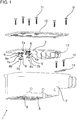
- FIGS. 1 and 2 An exemplary example of a contact socket 1 is in the FIGS. 1 and 2 reproduced in two different views, each in an exploded view.
- the contact socket 1 has a socket housing 2, which in the illustrated embodiment has two socket openings 5 for a plug unit, not shown here, wherein the socket openings 5 then serve to receive a pin housing of the plug unit.
- the socket openings 5 are limited in insertion directions of the plug unit by a socket bottom 9, which forms the bottom of the socket opening 5.
- the bush bottom 9 has openings 8a, 8b, which serve to receive pressure spring bodies 4a, 4b designed as contact elements, which are connected with their ends opposite the free ends to a printed circuit board 3.
- the circuit board 3 is located on the opposite side of the socket opening 5 on the socket bottom 9, wherein in the mounted state of the circuit board 3 on the socket bottom 9 pins 17 projecting on the socket bottom 9 by pin receptacles 18 on the circuit board 3.
- the compression spring bodies 4a, 4b which are soldered to intended contacts on the printed circuit board 3, have at their free end in each case a substantially perpendicular to the longitudinal axis of the socket opening 5 extending contact portion 7a, 7b.
- the contact portions 7a, 7b are formed corresponding to the end faces of the contact pins of the plug unit, not shown here, so as to ensure a reliable contact with each other.
- the contact pins in the assembled state of the plug unit to the contact socket 1, the contact pins displace the contact portions 7a, 7b in the direction of the circuit board 3, wherein in the region between the circuit board 3 and the contact portions 7a, 7b arranged deformation sections 6 of the compression spring body 4a, 4b are elastically deformed.
- compression spring bodies 4a, 4b This reduces the longitudinal extension of the compression spring bodies 4a, 4b in the longitudinal axis direction of the bushing openings.
- the deformation of the compression spring bodies 4a, 4b caused by the contact pins during assembly of the plug unit on the contact bush 1 is elastic, so that the spring force building up due to the elastic deformation ensures reliable contact of the compression spring bodies 4a, 4b with the contact pins.
- two different types of compression spring bodies 4a, 4b are arranged on the printed circuit board 3, wherein compression spring bodies 4a are Z-shaped and have a deformation region 6.
- the compression spring body 4b however, have a wave-shaped, two-section deformation region. 6
- the circuit board 10 is in addition to the pin 17 additionally secured by screws 11 to the socket bottom 9, wherein the screws 11 extend through holes 15 in the housing cover 10 and openings 16 in the circuit board 3 and are screwed into screw receptacles 14 in the socket bottom 9.
- a supplementary position assurance of the circuit board 3 is ensured by further screws 11, which extend through holes 15 in the housing cover 10 in the screw receptacles 14 of the female housing 2.
- a strain relief 13 which is clamped by screwing screws 11 into further screw receptacles 14 to the female housing 2 is used.
Abstract
Die Erfindung betrifft eine Kontaktbuchse (1) zur Aufnahme einer mindestens einen elektrisch leitenden Kontaktstift aufweisenden Steckereinheit, mit einer mit dem Kontaktstift kontaktierbaren Leiterplatte (3) und einer ein Kontaktstiftgehäuse aufnehmenden Buchsenöffnung (5). Um eine Kontaktbuchse bereitzustellen, deren Kontaktierung von Kontaktstift und Leiterplatte im Wesentlichen unabhängig von den Steckzyklen ist, ist vorgesehen, dass an der Leiterplatte ein vom Buchsenöffnungsgrund in die Buchsenöffnung vorstehendes Kontaktelement angeordnet ist, das mit einer Stirnfläche des Kontaktstifts in Eingriff bringbar ist und als in Richtung auf die Leiterplatte längenveränderlicher Druckfederkörper (4a, 4b) ausgebildet ist.

Description
Die Erfindung betrifft eine Kontaktbuchse zur Aufnahme einer mindestens einen elektrisch leitenden Kontaktstift aufweisenden Steckereinheit, mit
- einer mit dem Kontaktstift kontaktierbaren Leiterplatte und
- einer ein Kontaktstiftgehäuse aufnehmenden Buchsenöffnung.
- a contactable with the contact pin circuit board and
- a female contact opening receiving a female connector housing.
Kontaktbuchsen der eingangs genannten Art werden insbesondere in Kraftfahrzeugen u. a. dazu verwendet, um verschiedene elektronische Fahrzeugkomponenten miteinander zu verbinden. Die Kontaktbuchsen und die mit diesen zu verbindenden Steckereinheiten sind dabei aufeinander abgestimmt. Im Inneren der Kontaktbuchse sind dabei Anschlusskontakte für die Kontaktstifte der Steckereinheiten angeordnet, über die im montierten Zustand von Steckereinheit und Kontaktbuchse eine elektrisch leitende Verbindung hergestellt wird. Die Anschlusskontakte sind bspw. auf einer in der Kontaktbuchse angeordneten Leiterplatte angeordnet oder mit der Leiterplatte verbunden. Die Gehäuse von Kontaktbuchse und Steckereinheit sind dabei in ihrer Form so aufeinander abgestimmt, dass im montierten Zustand von Kontaktbuchse und Steckereinheit eine zuverlässige Anordnung der Gehäuse aneinander gewährleistet ist.Contact bushes of the type mentioned are in particular in motor vehicles u. a. used to interconnect various electronic vehicle components. The contact sockets and the connector units to be connected with these are matched to one another. In the interior of the contact socket while connecting contacts for the pins of the connector units are arranged, via which an electrically conductive connection is made in the assembled state of the plug unit and contact socket. The connection contacts are, for example, arranged on a printed circuit board arranged in the contact or connected to the circuit board. The housing of the contact socket and plug unit are matched in shape to one another, that in the assembled state of the contact socket and plug unit a reliable arrangement of the housing is guaranteed to each other.
Im montierten Zustand von Kontaktbuchse und Steckereinheit muss ferner gewährleistet werden, dass die Kontaktstifte elektrisch leitend mit den zugeordneten Kontakten an der Kontaktbuchse verbunden sind. Eine fehlerhafte oder unzulängliche Kontaktierung führt zu Übertragungsproblemen über die mittels Kontaktbuchse und Steckereinheit hergestellte Verbindung, was zu Störungen einzelner Systeme im Kraftfahrzeug oder sogar zum vollständigen Ausfall des Kraftfahrzeugs führen kann.In the mounted state of the contact socket and plug unit must also be ensured that the contact pins are electrically connected to the associated contacts on the contact socket. A faulty or inadequate contact leads to transmission problems over the connection made by means of contact socket and plug unit, which can lead to disturbances of individual systems in the motor vehicle or even to complete failure of the motor vehicle.
Eine solche Störung kann insbesondere dann auftreten, wenn die Steckverbindung mehrfach getrennt wurde, da bekannte Kontaktbuchsen der eingangs genannten Art den Nachteil aufweisen, dass diese nur bei einer geringen Anzahl von Steckzyklen eine zuverlässige elektrisch leitende Verbindung im montierten Zustand von Steckereinheit und Kontaktbuchse gewährleisten. Insbesondere im Anschluss an eine Kfz-Reparatur kann es somit in Folge wiederholter Trennungen von Kontaktbuchse und Steckereinheit dazu kommen, dass es aufgrund der damit einhergehenden Anzahl an Steckzyklen zu einer Störung der elektrisch leitenden Verbindung kommt. Darüber hinaus weisen die bekannten Kontaktbuchsen den Nachteil auf, dass diese auf der den Kontaktstiften abgewandten Seite der Leiterplatten einen erheblichen Bauraum für solche Bauelemente benötigen, die die Kontaktstifte in ihrer Position an den Kontakten der Leiterplatte sichern.Such a fault can occur in particular if the plug-in connection has been disconnected several times, since known contact sockets of the type mentioned at the outset have the disadvantage that they only become reliable in the case of a small number of mating cycles ensure electrically conductive connection in assembled condition of plug unit and contact socket. In particular, following a motor vehicle repair, as a result of repeated disconnections of the contact socket and plug unit, it may happen that the electrically conductive connection is disrupted due to the associated number of plug-in cycles. In addition, the known contact sockets have the disadvantage that they require a considerable space for such components on the side facing away from the pins of the circuit boards, which secure the contact pins in position on the contacts of the circuit board.
Hiervon ausgehend liegt der Erfindung die Aufgabe zugrunde, eine Kontaktbuchse bereitzustellen, deren Kontaktierung von Kontaktstift und Leiterplatte im Wesentlichen unabhängig von den Steckzyklen ist.Proceeding from this, the object of the invention is to provide a contact socket whose contacting of the contact pin and the printed circuit board is essentially independent of the mating cycles.
Die Erfindung löst die Aufgabe durch eine Kontaktbuchse mit den Merkmalen des Anspruchs 1. Vorteilhafte Weiterbildungen der Erfindung sind in den abhängigen Ansprüchen angegeben.The invention solves the problem by a contact socket having the features of
Kennzeichnend für die erfindungsgemäße Kontaktbuchse ist, dass an der Leiterplatte ein vom Buchsenöffnungsgrund in die Buchsenöffnung vorstehendes Kontaktelement angeordnet ist, das mit einer Stirnfläche des Kontaktstifts einer Steckereinheit in Eingriff bringbar ist und als in Richtung auf die Leiterplatte längenveränderlicher Druckfederkörper ausgebildet ist. Unter längenveränderlich wird dabei die Eignung der Druckfederkörper angesehen, die Erstreckung in Längsachsenrichtung elastisch zu verändern. Eine elastische Verformung erfolgt dabei durch die Montage der Steckereinheit an der Kontaktbuchse, bei der der Druckfederkörper durch den Kontaktstift in Richtung auf die Leiterplatte elastisch verformt wird.Characteristic of the contact socket according to the invention is that on the circuit board arranged from the Buchsenöffnungsgrund in the socket opening contact element is arranged, which is engageable with an end face of the contact pin of a plug unit and formed as a variable length in the direction of the printed circuit board pressure spring body. Under variable length while the suitability of the compression spring body is considered to change the extension in the longitudinal axis direction elastic. An elastic deformation takes place by the assembly of the plug unit to the contact socket, in which the compression spring body is elastically deformed by the contact pin in the direction of the circuit board.
Gemäß der Erfindung ist dabei der mit dem Kontaktstift der Steckereinheit zu kontaktierende Kontakt auf der Leiterplatte mit einem als Druckfederkörper ausgebildeten Kontaktelement verbunden, welches mit seinem der Leiterplatte gegenüberliegenden freien Ende von einem Buchsenöffnungsgrund der Kontaktbuchse in die Buchsenöffnung vorsteht.In accordance with the invention, the contact to be contacted with the contact pin of the plug unit is connected to the printed circuit board with a contact element designed as a compression spring body, which protrudes with its free end opposite the printed circuit board from a socket opening base of the contact socket into the socket opening.
Die Ausgestaltung des Kontaktelements als Druckfederkörper ist dabei derart, dass bei einer Verbindung von Kontaktbuchse und Steckereinheit eine oder mehrere Kontaktstifte der Steckereinheit mit ihren Stirnflächen an den zugeordneten Druckfederkörpern anliegen. In der montierten Lage bewirkt die durch die Kontaktstifte hervorgerufene elastische Verformung der Druckfederkörper eine kraftschlüssige Anlage der Druckfederkörper an den Stirnseiten der Kontaktstifte. Die Kontaktstifte können dabei grundsätzlich jede beliebige Form aufweisen, bspw. als Flachstecker oder zylindrische Stifte ausgebildet sein, wobei ggf. die Druckfederkörper bevorzugt entsprechend ausgebildete Anlageflächen aufweisen, sodass im Falle einer Montage die Stirnseiten der Kontaktstifte zuverlässig an den Druckfederkörpern zur Anlage kommen und diese elastisch verformen, sodass deren Längserstreckung in Richtung auf die Kontaktstifte verändert wird.The design of the contact element as a compression spring body is such that at a Connection of contact socket and plug unit one or more pins of the plug unit with their end faces abut the associated compression spring bodies. In the mounted position causes caused by the contact pins elastic deformation of the compression spring body frictional contact of the compression spring body on the end faces of the contact pins. The contact pins can basically have any shape, for example. Be designed as a flat plug or cylindrical pins, where appropriate, the compression spring body preferably have trained trained contact surfaces, so that in case of mounting the front sides of the pins reliably to the compression spring bodies come into contact and this elastic deform, so that their longitudinal extent is changed in the direction of the contact pins.
Die Ausgestaltung der Kontaktstifte als in Längsachsenrichtung der Buchsenöffnungen bzw. in Richtung auf die Leiterplatte längenveränderliche Druckfederkörper ermöglicht es, die durch die Bewegung der Kontaktstifte beim Verbinden von Steckereinheit und Kontaktbuchse auftretende Verlagerung dazu zu verwenden, die Druckfederkörper elastisch zu verformen, sodass die Rückverformungsenergie eine zuverlässige Anlage der Kontaktstifte an den mit der Leiterplatte verbundenen Druckfederkörpern gewährleistet. Eine Auslegung der Druckfederkörper derart, dass diese bei einer Kontaktierung von Kontaktbuchse und Steckereinheit nur im elastischen Bereich verformt werden, gewährleistet dabei in besonders zuverlässiger Weise, dass steckzyklenunabhängig eine zuverlässige Kontaktierung gewährleistet ist.The design of the contact pins as in the longitudinal axis direction of the socket openings or in the direction of the circuit board variable-length compression spring body makes it possible to use the displacement occurring by the movement of the contact pins when connecting plug unit and contact socket to elastically deform the compression spring body, so that the recovery energy is a reliable Ensures contact of the contact pins connected to the circuit board compression spring bodies. An interpretation of the compression spring body such that they are deformed at a contact between the contact socket and plug unit only in the elastic range, thereby ensuring in a particularly reliable manner that Steckzyklenunabhängig reliable contact is guaranteed.
Die Ausgestaltung des Druckfederkörpers derart, dass dieser bei einem Einführen des Kontaktstifts in die Kontaktbuchse und beim Verbinden von Kontaktbuchse und Steckereinheit eine elastische Verformung erfährt, ist grundsätzlich frei wählbar. So kann der Druckfederkörper bspw. als Schraubendruckfeder ausgelegt sein, welche einenends an der Leiterplatte angeordnet ist und anderenends zur Kontaktierung mit dem Kontaktstift der Steckereinheit ausgebildet ist, welcher in der montierten Lage von Steckereinheit und Kontaktbuchse eine Verformung der Schraubendruckfeder im elastischen Bereich bewirkt.The design of the compression spring body such that it undergoes an elastic deformation during insertion of the contact pin into the contact socket and when connecting the contact socket and plug unit is basically freely selectable. Thus, the compression spring body, for example, be designed as a helical compression spring, which is arranged at one end to the circuit board and the other end is designed for contacting with the contact pin of the plug unit, which causes a deformation of the helical compression spring in the elastic region in the assembled position of plug unit and contact socket.
Nach einer besonders vorteilhaften Ausgestaltung der Erfindung ist jedoch vorgesehen, dass der Druckfederkörper mindestens einen gegenüber der Buchsenöffnungslängsachse geneigten Deformationsabschnitt aufweist. Gemäß dieser Ausgestaltung der Erfindung ist vorgesehen, dass der Druckfederkörper zumindest einen Abschnitt aufweist, welcher sich quer zur Längsachse der Buchsenöffnung erstreckt, d. h. unter einem Winkel kleiner als 90° und größer als 0° zur Längsachse verläuft. Die Längsachse der Buchsenöffnung entspricht dabei der Achse, entlang derer sich der Kontaktstift bei der Montage der Steckereinheit an der Kontaktbuchse bewegt. Die Verwendung eines geneigten Deformationsabschnittes gewährleistet in besonders einfacher Weise die Ausbildung eines elastisch verformbaren Druckfederkörpers, wobei im Zusammenwirken mit dem Kontaktstift in der Regel die Neigung des Deformationsabschnittes gegenüber der Buchsenöffnungslängsachse erhöht wird. In einer besonders einfachen Ausgestaltung kann bspw. der Druckfederkörper Z-förmig ausgestaltet sein, wobei dieser einenends an der Leiterplatte anliegt und anderenends zum Kontakt mit dem Kontaktstift ausgebildet ist.According to a particularly advantageous embodiment of the invention, however, it is provided that the pressure spring body has at least one deformation section which is inclined relative to the bush opening longitudinal axis. According to this embodiment of the invention, it is provided in that the compression spring body has at least one section which extends transversely to the longitudinal axis of the bushing opening, ie extends at an angle of less than 90 ° and greater than 0 ° to the longitudinal axis. The longitudinal axis of the socket opening corresponds to the axis along which the contact pin moves during assembly of the plug unit to the contact socket. The use of an inclined deformation section ensures in a particularly simple manner the formation of an elastically deformable pressure spring body, wherein in cooperation with the contact pin usually the inclination of the deformation section relative to the bush opening longitudinal axis is increased. In a particularly simple embodiment, for example, the compression spring body Z-shaped be configured, wherein this one end abuts the circuit board and the other end is designed to contact the contact pin.
Eine Kontaktierung des Kontaktstifts mit dem Druckfederkörper ist bei einer entsprechenden Ausgestaltung des Druckfederkörpers grundsätzlich besonders einfach realisierbar. Nach einer besonders vorteilhaften Ausgestaltung der Erfindung ist jedoch vorgesehen, dass das freie Ende des Druckfederkörpers einen im Wesentlichen senkrecht zur Buchsenöffnungslängsachse verlaufenden Kontaktabschnitt aufweist. Die Anordnung eines quer zur Einschubrichtung des Kontaktstifts in die Buchsenöffnung verlaufenden Kontaktabschnitts gewährleistet in besonders zuverlässiger Weise, dass der Kontaktstift mit seiner Stirnseite zuverlässig an dem Druckfederkörper anliegt. Bei einem als Flachstecker ausgebildeten Kontaktstift ermöglicht bspw. die Verwendung eines quer zur Buchsenöffnungslängsachse verlaufenden Kontaktabschnitts eine breite Kontaktfläche zwischen dem Kontaktstift und dem Kontaktelement, sodass zuverlässig sowohl eine elektrisch leitende Verbindung hergestellt wird als auch eine ausreichende Anlage des Druckfederkörpers an dem Kontaktstift besteht.A contacting of the contact pin with the compression spring body is basically particularly easy to implement in a corresponding embodiment of the compression spring body. According to a particularly advantageous embodiment of the invention, however, it is provided that the free end of the compression spring body has a substantially perpendicular to the bush opening longitudinal axis extending contact portion. The arrangement of a transverse to the insertion direction of the contact pin in the socket opening extending contact portion ensures in a particularly reliable manner that the contact pin rests reliably with its end face on the compression spring body. In the case of a contact pin embodied as a flat plug, for example, the use of a contact section running transversely to the socket opening longitudinal axis enables a wide contact surface between the contact pin and the contact element, so that reliably both an electrically conductive connection is produced and there is sufficient contact of the compression spring body with the contact pin.
Die Lagesicherung des Druckfederkörpers innerhalb der Kontaktbuchse und dessen Kontaktierung mit der Leiterplatte kann grundsätzlich in beliebiger Weise erfolgen. Nach einer besonders vorteilhaften Ausgestaltung der Erfindung ist jedoch vorgesehen, dass der Druckfederkörper durch eine Öffnung in einem den Buchsenöffnungsgrund bildenden Buchsenboden hindurchragt.The position assurance of the compression spring body within the contact socket and its contact with the circuit board can basically be done in any way. According to a particularly advantageous embodiment of the invention, however, it is provided that the pressure spring body protrudes through an opening in a socket bottom forming the bushing opening base.
Gemäß dieser Ausgestaltung der Erfindung ist die Buchsenöffnung durch einen Buchsenboden begrenzt, welcher Öffnungen aufweist, durch die eine oder mehrere mit der Leiterplatte verbundene Druckfederkörper hindurchragen. Die Verwendung eines mit Öffnungen versehenen Buchsenbodens gewährleistet durch die Öffnungen eine zuverlässige Lagesicherung der Druckfederkörper. Diese sind durch die Öffnung randseitig geführt, sodass einer fehlerhaften Ausweichbewegung der Druckfederkörper im Zusammenwirken mit den Kontaktstiften vorgebeugt wird. Darüber hinaus ermöglicht diese Ausgestaltung der Erfindung auch eine zuverlässige Lagesicherung der Druckfederkörper an den Kontakten der Leiterplatte, welche besonders bevorzugt auf der der Buchsenöffnung gegenüberliegenden Seite an dem Buchsenboden anliegt, sodass die Kontaktbuchse eine besonders geringe Bauhöhe aufweist.According to this embodiment of the invention, the socket opening is through a socket bottom limited, which has openings through which protrude one or more of the printed circuit board connected to the pressure spring body. The use of an apertured bush bottom ensures through the openings a reliable position securing the compression spring body. These are guided by the edge of the opening, so that a faulty evasive movement of the compression spring body is prevented in cooperation with the contact pins. In addition, this embodiment of the invention also enables a reliable position securing the pressure spring body to the contacts of the circuit board, which particularly preferably rests on the opposite side of the bushing opening on the socket bottom, so that the contact socket has a particularly low overall height.
Die Befestigung der Leiterplatte an der Kontaktbuchse ist dabei ebenfalls grundsätzlich frei wählbar. Nach einer besonders vorteilhaften Ausgestaltung der Erfindung ist die Leiterplatte jedoch an dem Buchsenboden befestigt, insbesondere mit diesem verschraubt. Eine entsprechende Ausgestaltung der Erfindung gewährleistet eine zuverlässige Lagesicherung der Leiterplatte an der Kontaktbuchse, wobei im Falle der vorteilhafterweise vorgesehenen Ausgestaltung der Erfindung, wonach die Druckfederkörper durch Öffnungen in dem Buchsenboden ragen, durch eine Befestigung der Leiterplatte an dem Buchsenboden, insbesondere durch eine Verschraubung eine besonders zuverlässige Lagesicherung der Druckfederkörper innerhalb der Buchsenöffnung erreicht werden kann.The attachment of the circuit board to the contact socket is also basically arbitrary. According to a particularly advantageous embodiment of the invention, however, the circuit board is attached to the socket bottom, in particular bolted to this. A corresponding embodiment of the invention ensures a reliable position assurance of the circuit board to the contact socket, wherein in the case of advantageously provided embodiment of the invention, according to which the pressure spring body protrude through openings in the socket bottom, by attaching the circuit board to the socket bottom, in particular by a screw a particularly reliable position securing the compression spring body can be achieved within the socket opening.
Die Verbindung der als Druckfederkörper ausgebildeten Kontaktelemente mit den entsprechenden Kontakten an der Leiterplatte ist grundsätzlich frei wählbar. So können diese bspw. durch geeignete Kleber elektrisch leitend mit den Kontaktstellen an der Leiterplatte verbunden werden. Nach einer besonders vorteilhaften Ausgestaltung der Erfindung ist jedoch vorgesehen, dass die Druckfederkörper an die Leiterplatte angelötet sind. Die Lötverbindung lässt sich besonders einfach und kostengünstig herstellen und gewährleistet in besonders zuverlässiger Weise eine elektrische Kontaktierung der Druckfederkörper mit der Leiterplatte.The connection of the trained as a compression spring body contact elements with the corresponding contacts on the circuit board is basically arbitrary. For example, they can be electrically conductively connected to the contact points on the circuit board by suitable adhesives. According to a particularly advantageous embodiment of the invention, however, it is provided that the compression spring bodies are soldered to the circuit board. The solder joint can be produced in a particularly simple and cost-effective manner and ensures, in a particularly reliable manner, electrical contacting of the compression spring bodies with the printed circuit board.
Nach einer weiteren Ausgestaltung der Erfindung ist ferner vorgesehen, dass die Leiterplatte an einem Gehäusedeckel anliegt. Gemäß dieser Ausgestaltung der Erfindung wird ein Gehäusekörper der Kontaktbuchse durch einen Gehäusedeckel verschlossen, welcher unmittelbar an der Leiterplatte anliegt und diese somit in ihrer Position innerhalb der Kontaktbuchse sichert. Darüber hinaus wird durch eine Anlage des Gehäusedeckels an der Leiterplatte, wobei die Anlage auch punktuell ausgeführt sein kann, gewährleistet, dass die Bauhöhe der Kontaktbuchse besonders gering ausgestaltet ist.According to a further embodiment of the invention it is further provided that the circuit board rests against a housing cover. According to this embodiment of the invention, a housing body of the contact socket is closed by a housing cover, which immediately rests against the circuit board and thus secures them in position within the contact socket. In addition, it is ensured by a plant of the housing cover on the circuit board, the system can also be punctual, ensures that the height of the contact socket is designed to be particularly low.
Ein Ausführungsbeispiel der Erfindung wird nachstehend mit Bezug auf die Zeichnungen erläutert. In den Zeichnungen zeigen:
Figur 1- eine erste Explosionsdarstellung einer Kontaktbuchse und
Figur 2- eine zweite Explosionsdarstellung der Kontaktbuchse von
Figur 1
- FIG. 1
- a first exploded view of a contact socket and
- FIG. 2
- a second exploded view of the contact socket of
FIG. 1 ,
Ein Ausführungsbespiel einer Kontaktbuchse 1 ist in den
Die Kontaktbuchse 1 weist ein Buchsengehäuse 2 auf, welches in dem dargestellten Ausführungsbeispiel zwei Buchsenöffnungen 5 für eine hier nicht dargestellte Steckereinheit aufweist, wobei die Buchsenöffnungen 5 dann zur Aufnahme eines Kontaktstiftgehäuses der Steckereinheit dienen.The
Die Buchsenöffnungen 5 sind in Einschubrichtungen der Steckereinheit durch einen Buchsenboden 9 begrenzt, welcher den Grund der Buchsenöffnung 5 bildet. Der Buchsenboden 9 weist Öffnungen 8a, 8b auf, welche zur Aufnahme von als Kontaktelementen ausgebildeten Druckfederkörpern 4a, 4b dienen, welche mit ihren den freien Enden gegenüberliegenden Enden mit einer Leiterplatte 3 verbunden sind. Die Leiterplatte 3 liegt auf der der Buchsenöffnung 5 gegenüberliegenden Seite an dem Buchsenboden 9 an, wobei im montierten Zustand der Leiterplatte 3 an dem Buchsenboden 9 Zapfen 17 an dem Buchsenboden 9 durch Zapfenaufnahmen 18 an der Leiterplatte 3 hindurchragen.The
Die Druckfederkörper 4a, 4b, welche an vorgesehene Kontakte an der Leiterplatte 3 angelötet sind, weisen an ihrem freien Ende jeweils einen im Wesentlichen senkrecht zur Längsachse der Buchsenöffnung 5 verlaufende Kontaktabschnitt 7a, 7b auf. Die Kontaktabschnitte 7a, 7b sind entsprechend der Stirnseiten der hier nicht dargestellten Kontaktstifte der Steckereinheit ausgebildet, um so eine zuverlässige Anlage aneinander zu gewährleisten. Im montierten Zustand der Steckereinheit an der Kontaktbuchse 1 verlagern die Kontaktstifte die Kontaktabschnitte 7a, 7b in Richtung auf die Leiterplatte 3, wobei im Bereich zwischen der Leiterplatte 3 und den Kontaktabschnitten 7a, 7b angeordnete Deformationsabschnitte 6 der Druckfederkörper 4a, 4b elastisch verformt werden. Hierdurch verringert sich die Längserstreckung der Druckfederkörper 4a, 4b in Längsachsenrichtung der Buchsenöffnungen. Die durch die Kontaktstifte bei der Montage der Steckereinheit an der Kontaktbuchse 1 hervorgerufene Verformung der Druckfederkörper 4a, 4b ist elastisch, sodass die sich aufgrund der elastischen Verformung aufbauende Federkraft eine zuverlässige Anlage der Druckfederkörper 4a, 4b an den Kontaktstiften gewährleistet. Im vorliegenden Ausführungsbeispiel sind an der Leiterplatte 3 zwei unterschiedliche Arten von Druckfederkörpern 4a, 4b angeordnet, wobei Druckfederkörper 4a Z-förmig ausgebildet sind und einen Deformationsbereich 6 aufweisen. Die Druckfederkörper 4b besitzen hingegen einen wellenförmigen, zwei Abschnitte aufweisenden Deformationsbereich 6.The
Die Leiterplatte 10 ist neben den Zapfen 17 zusätzlich über Schrauben 11 an dem Buchsenboden 9 gesichert, wobei sich die Schrauben 11 durch Bohrungen 15 in dem Gehäusedeckel 10 sowie Öffnungen 16 in der Leiterplatte 3 erstrecken und in Schraubenaufnahmen 14 in dem Buchsenboden 9 eingeschraubt sind. Eine ergänzende Lagesicherung der Leiterplatte 3 wird durch weitere Schrauben 11 gewährleistet, welche sich durch Bohrungen 15 in dem Gehäusedeckel 10 in Schraubenaufnahmen 14 des Buchsengehäuses 2 erstrecken. Für eine Zugentlastung eines mit Flachsteckhülsen 12 an der Leiterplatte 3 verbundenen, hier nicht dargestellten Kabels dient ein Zugentlastungselement 13, welches durch das Einschrauben von Schrauben 11 in weitere Schraubenaufnahmen 14 an dem Buchsengehäuse 2 festklemmt wird.The
- 11
- KontaktbuchseContact socket
- 22
- Buchsengehäusesocket housing
- 33
- Leiterplattecircuit board
- 4a, 4b4a, 4b
- Kontaktelement/DruckfederkörperContact element / spring body
- 55
- Buchsenöffnungsocket opening
- 66
- Deformationsabschnittdeformation section
- 7a, 7b7a, 7b
- KontaktabschnittContact section
- 8a, 8b8a, 8b
- Öffnungopening
- 99
- Buchsenbodensocket ground
- 1010
- Gehäusedeckelhousing cover
- 1111
- Schraubenscrew
- 1212
- FlachsteckhülseBlade receptacle
- 1313
- Zugentlastungselementstrain relief
- 1414
- Schraubenaufnahmenscrew mounts
- 1515
- Bohrungendrilling
- 1616
- Öffnungenopenings
- 1717
- Zapfenspigot
- 1818
- Zapfenaufnahmepin receiver
Claims (7)
an der Leiterplatte (3) ein vom Buchsenöffnungsgrund in die Buchsenöffnung (5) vorstehendes Kontaktelement angeordnet ist, das mit einer Stirnfläche des Kontaktstifts in Eingriff bringbar ist und als in Richtung auf die Leiterplatte (3) längenveränderlicher Druckfederkörper (4a, 4b) ausgebildet ist.Contact socket for receiving a plug-in unit having at least one electrically conductive contact pin, with
on the printed circuit board (3) a contact element projecting from the socket opening in the socket opening (5) is arranged, which is engageable with an end face of the contact pin and as in the direction of the printed circuit board (3) variable-length compression spring body (4a, 4b) is formed.
Applications Claiming Priority (1)
| Application Number | Priority Date | Filing Date | Title |
|---|---|---|---|
| DE102017107142.3A DE102017107142A1 (en) | 2017-04-03 | 2017-04-03 | Contact socket |
Publications (1)
| Publication Number | Publication Date |
|---|---|
| EP3386035A1 true EP3386035A1 (en) | 2018-10-10 |
Family
ID=61868260
Family Applications (1)
| Application Number | Title | Priority Date | Filing Date |
|---|---|---|---|
| EP18165067.2A Withdrawn EP3386035A1 (en) | 2017-04-03 | 2018-03-29 | Contact socket |
Country Status (3)
| Country | Link |
|---|---|
| US (1) | US20180287284A1 (en) |
| EP (1) | EP3386035A1 (en) |
| DE (1) | DE102017107142A1 (en) |
Citations (6)
| Publication number | Priority date | Publication date | Assignee | Title |
|---|---|---|---|---|
| EP0228859A2 (en) * | 1985-12-16 | 1987-07-15 | Thomas & Betts Corporation | Detachable electrical connector |
| JPH0640497B2 (en) * | 1989-06-07 | 1994-05-25 | 矢崎総業株式会社 | Printed wiring board terminals |
| JPH0794247A (en) * | 1993-07-27 | 1995-04-07 | Nec Corp | Structure for connector |
| JP3005425B2 (en) * | 1994-07-13 | 2000-01-31 | 株式会社ピーエフユー | Multi-contact connector |
| US6071129A (en) * | 1997-10-30 | 2000-06-06 | Mitsumi Electric Co., Ltd. | Connector socket with contact enlarged base sections inserted in holding chamber attachment grooves and stopping projections in chamber to prevent contact from being withdrawn from chamber |
| JP2014165115A (en) * | 2013-02-27 | 2014-09-08 | Yazaki Corp | Magnet connector |
Family Cites Families (19)
| Publication number | Priority date | Publication date | Assignee | Title |
|---|---|---|---|---|
| US4179171A (en) * | 1978-03-03 | 1979-12-18 | Shannon Shelly L | Electrical connector |
| US4836791A (en) * | 1987-11-16 | 1989-06-06 | Amp Incorporated | High density coax connector |
| FR2623945B1 (en) * | 1987-11-30 | 1990-04-27 | Marechal Sepm | POWER SOCKET WITH PRESSURE CONTACTS |
| US5791914A (en) * | 1995-11-21 | 1998-08-11 | Loranger International Corporation | Electrical socket with floating guide plate |
| US6920689B2 (en) * | 2002-12-06 | 2005-07-26 | Formfactor, Inc. | Method for making a socket to perform testing on integrated circuits |
| US6969801B2 (en) * | 2003-08-21 | 2005-11-29 | Pass & Seymour, Inc. | Shuttered receptacle for a protective device |
| US7312963B1 (en) * | 2003-12-05 | 2007-12-25 | Pass & Seymour, Inc. | Protective device with tamper resistant shutters |
| US7554033B1 (en) * | 2003-12-05 | 2009-06-30 | Pass & Seymour, Inc. | Environmentally Protected Wiring Device |
| US7400239B2 (en) * | 2004-09-03 | 2008-07-15 | Simply Automated, Incorporated | Universal control apparatus and methods |
| ITMI20050072U1 (en) * | 2005-03-07 | 2006-09-08 | Ilme Spa | ELECTRIC CONNECTOR ELEMENT WITH SPRING READABLE CONTACTS |
| US8162684B1 (en) * | 2008-08-07 | 2012-04-24 | Jerzy Roman Sochor | Implantable connector with contact-containing feedthrough pins |
| US7837481B1 (en) * | 2008-01-14 | 2010-11-23 | Xilinx, Inc. | Socket for an integrated circuit and a method of providing a connection in a socket |
| US7462074B1 (en) * | 2008-02-06 | 2008-12-09 | Southwire Company | Rotating plug adapter with integral two blade and grounding post receptacle |
| US8926350B2 (en) * | 2012-05-17 | 2015-01-06 | Shawn M. Wolfe | Protective lockable female electrical outlet |
| US8408946B1 (en) * | 2012-05-26 | 2013-04-02 | Jerzy Roman Sochor | Low inductance contact with conductively coupled pin |
| US8956166B2 (en) * | 2012-05-31 | 2015-02-17 | Hi Rel Connectors, Inc. | Apparatus for electrically connecting a flexible circuit to a receiver |
| GB2526369B (en) * | 2014-05-23 | 2019-06-26 | Itt Mfg Enterprises Llc | Electrical connector |
| CN204361885U (en) * | 2015-01-05 | 2015-05-27 | 富士康(昆山)电脑接插件有限公司 | Power supply adaptor |
| CN204834972U (en) * | 2015-03-25 | 2015-12-02 | 宏致电子股份有限公司 | Two -way formula electric connector that continues |
-
2017
- 2017-04-03 DE DE102017107142.3A patent/DE102017107142A1/en not_active Ceased
-
2018
- 2018-03-29 EP EP18165067.2A patent/EP3386035A1/en not_active Withdrawn
- 2018-04-03 US US15/943,879 patent/US20180287284A1/en not_active Abandoned
Patent Citations (6)
| Publication number | Priority date | Publication date | Assignee | Title |
|---|---|---|---|---|
| EP0228859A2 (en) * | 1985-12-16 | 1987-07-15 | Thomas & Betts Corporation | Detachable electrical connector |
| JPH0640497B2 (en) * | 1989-06-07 | 1994-05-25 | 矢崎総業株式会社 | Printed wiring board terminals |
| JPH0794247A (en) * | 1993-07-27 | 1995-04-07 | Nec Corp | Structure for connector |
| JP3005425B2 (en) * | 1994-07-13 | 2000-01-31 | 株式会社ピーエフユー | Multi-contact connector |
| US6071129A (en) * | 1997-10-30 | 2000-06-06 | Mitsumi Electric Co., Ltd. | Connector socket with contact enlarged base sections inserted in holding chamber attachment grooves and stopping projections in chamber to prevent contact from being withdrawn from chamber |
| JP2014165115A (en) * | 2013-02-27 | 2014-09-08 | Yazaki Corp | Magnet connector |
Also Published As
| Publication number | Publication date |
|---|---|
| US20180287284A1 (en) | 2018-10-04 |
| DE102017107142A1 (en) | 2018-10-04 |
Similar Documents
| Publication | Publication Date | Title |
|---|---|---|
| DE10330904B4 (en) | Connector assembly for electrical connection | |
| EP2481126B1 (en) | Multifork pressing pin | |
| EP2639894B1 (en) | Electrical connector with tolerance compensation | |
| EP1929848B1 (en) | Connection of two semi-conductor plates or flat components by means of a mechanical lock | |
| EP2380241B1 (en) | Contact-making plug and contact-making plug connection | |
| DE10355456A1 (en) | Device and method for contacting a printed circuit board by means of a connector | |
| DE102015015202A1 (en) | Connector and plug-in system | |
| DE102019119588A1 (en) | Contact element for the electrical connection of circuit cards and method for assembling a circuit card arrangement | |
| EP1249895B1 (en) | Electrical connector | |
| DE102007039064A1 (en) | Electronic device for use as control device for pump, has plug connector with two connector pins and contact holder holding connector pins and connector pin is arranged above and below printed circuit board | |
| EP3386035A1 (en) | Contact socket | |
| DE10243407B4 (en) | Fixing device for a plug | |
| DE10047126B4 (en) | fastening device | |
| DE102009002999A1 (en) | Contact pin for electronic circuit of controller for controlling internal combustion engine of motor vehicle, has contact element connected with electrical circuit, where base segment and contact element are connected to each other | |
| DE202015002712U1 (en) | Mounting device for a connection element | |
| DE202019003587U1 (en) | Press-in contact | |
| DE102019131486B4 (en) | Electrical contact arrangement | |
| DE202015006560U1 (en) | Connection element with positioning | |
| WO2021198069A1 (en) | Axially resilient pressing contact pin | |
| WO2006074709A1 (en) | Contact partner for mounting on a printed circuit board | |
| EP0966777B1 (en) | Electric subassembly | |
| WO2023062009A1 (en) | Sensor module | |
| DE102017107470A1 (en) | Plug-in element for connection to a printed circuit board with through holes | |
| WO2023046532A1 (en) | Plug connector part with a shield support | |
| DE202022000146U1 (en) | Fastening element self-locking |
Legal Events
| Date | Code | Title | Description |
|---|---|---|---|
| PUAI | Public reference made under article 153(3) epc to a published international application that has entered the european phase |
Free format text: ORIGINAL CODE: 0009012 |
|
| STAA | Information on the status of an ep patent application or granted ep patent |
Free format text: STATUS: THE APPLICATION HAS BEEN PUBLISHED |
|
| AK | Designated contracting states |
Kind code of ref document: A1 Designated state(s): AL AT BE BG CH CY CZ DE DK EE ES FI FR GB GR HR HU IE IS IT LI LT LU LV MC MK MT NL NO PL PT RO RS SE SI SK SM TR |
|
| AX | Request for extension of the european patent |
Extension state: BA ME |
|
| STAA | Information on the status of an ep patent application or granted ep patent |
Free format text: STATUS: REQUEST FOR EXAMINATION WAS MADE |
|
| 17P | Request for examination filed |
Effective date: 20190325 |
|
| RBV | Designated contracting states (corrected) |
Designated state(s): AL AT BE BG CH CY CZ DE DK EE ES FI FR GB GR HR HU IE IS IT LI LT LU LV MC MK MT NL NO PL PT RO RS SE SI SK SM TR |
|
| STAA | Information on the status of an ep patent application or granted ep patent |
Free format text: STATUS: EXAMINATION IS IN PROGRESS |
|
| 17Q | First examination report despatched |
Effective date: 20200406 |
|
| STAA | Information on the status of an ep patent application or granted ep patent |
Free format text: STATUS: THE APPLICATION HAS BEEN WITHDRAWN |
|
| 18W | Application withdrawn |
Effective date: 20200623 |