EP3385969B1 - Gas-insulated circuit breaker and a method for breaking an electrical connection - Google Patents
Gas-insulated circuit breaker and a method for breaking an electrical connection Download PDFInfo
- Publication number
- EP3385969B1 EP3385969B1 EP18164863.5A EP18164863A EP3385969B1 EP 3385969 B1 EP3385969 B1 EP 3385969B1 EP 18164863 A EP18164863 A EP 18164863A EP 3385969 B1 EP3385969 B1 EP 3385969B1
- Authority
- EP
- European Patent Office
- Prior art keywords
- gas
- circuit breaker
- insulated circuit
- pin
- absorption element
- Prior art date
- Legal status (The legal status is an assumption and is not a legal conclusion. Google has not performed a legal analysis and makes no representation as to the accuracy of the status listed.)
- Active
Links
- 238000000034 method Methods 0.000 title claims description 14
- 238000010521 absorption reaction Methods 0.000 claims description 164
- 238000013016 damping Methods 0.000 claims description 45
- 239000006096 absorbing agent Substances 0.000 claims description 28
- 241000722921 Tulipa gesneriana Species 0.000 claims description 22
- 238000007789 sealing Methods 0.000 claims description 8
- 230000005540 biological transmission Effects 0.000 claims description 7
- 238000000926 separation method Methods 0.000 description 6
- 230000000694 effects Effects 0.000 description 5
- 230000006835 compression Effects 0.000 description 3
- 238000007906 compression Methods 0.000 description 3
- 230000004044 response Effects 0.000 description 3
- 229910018503 SF6 Inorganic materials 0.000 description 2
- 238000009413 insulation Methods 0.000 description 2
- SFZCNBIFKDRMGX-UHFFFAOYSA-N sulfur hexafluoride Chemical compound FS(F)(F)(F)(F)F SFZCNBIFKDRMGX-UHFFFAOYSA-N 0.000 description 2
- 229960000909 sulfur hexafluoride Drugs 0.000 description 2
- 230000001133 acceleration Effects 0.000 description 1
- 238000013459 approach Methods 0.000 description 1
- 230000008901 benefit Effects 0.000 description 1
- 239000000872 buffer Substances 0.000 description 1
- 230000000295 complement effect Effects 0.000 description 1
- 238000010586 diagram Methods 0.000 description 1
- 238000010891 electric arc Methods 0.000 description 1
- 239000011796 hollow space material Substances 0.000 description 1
- 230000000977 initiatory effect Effects 0.000 description 1
- 238000012986 modification Methods 0.000 description 1
- 230000004048 modification Effects 0.000 description 1
- 238000010791 quenching Methods 0.000 description 1
- 230000007704 transition Effects 0.000 description 1
Images


Classifications
-
- H—ELECTRICITY
- H01—ELECTRIC ELEMENTS
- H01H—ELECTRIC SWITCHES; RELAYS; SELECTORS; EMERGENCY PROTECTIVE DEVICES
- H01H33/00—High-tension or heavy-current switches with arc-extinguishing or arc-preventing means
- H01H33/70—Switches with separate means for directing, obtaining, or increasing flow of arc-extinguishing fluid
- H01H33/72—Switches with separate means for directing, obtaining, or increasing flow of arc-extinguishing fluid having stationary parts for directing the flow of arc-extinguishing fluid, e.g. arc-extinguishing chamber
- H01H33/74—Switches with separate means for directing, obtaining, or increasing flow of arc-extinguishing fluid having stationary parts for directing the flow of arc-extinguishing fluid, e.g. arc-extinguishing chamber wherein the break is in gas
-
- H—ELECTRICITY
- H01—ELECTRIC ELEMENTS
- H01H—ELECTRIC SWITCHES; RELAYS; SELECTORS; EMERGENCY PROTECTIVE DEVICES
- H01H3/00—Mechanisms for operating contacts
- H01H3/60—Mechanical arrangements for preventing or damping vibration or shock
- H01H3/605—Mechanical arrangements for preventing or damping vibration or shock making use of a fluid damper
-
- H—ELECTRICITY
- H01—ELECTRIC ELEMENTS
- H01H—ELECTRIC SWITCHES; RELAYS; SELECTORS; EMERGENCY PROTECTIVE DEVICES
- H01H33/00—High-tension or heavy-current switches with arc-extinguishing or arc-preventing means
- H01H33/02—Details
- H01H33/04—Means for extinguishing or preventing arc between current-carrying parts
- H01H33/12—Auxiliary contacts on to which the arc is transferred from the main contacts
- H01H33/121—Load break switches
-
- H—ELECTRICITY
- H01—ELECTRIC ELEMENTS
- H01H—ELECTRIC SWITCHES; RELAYS; SELECTORS; EMERGENCY PROTECTIVE DEVICES
- H01H33/00—High-tension or heavy-current switches with arc-extinguishing or arc-preventing means
- H01H33/02—Details
- H01H33/28—Power arrangements internal to the switch for operating the driving mechanism
- H01H33/30—Power arrangements internal to the switch for operating the driving mechanism using fluid actuator
- H01H33/32—Power arrangements internal to the switch for operating the driving mechanism using fluid actuator pneumatic
-
- H—ELECTRICITY
- H01—ELECTRIC ELEMENTS
- H01H—ELECTRIC SWITCHES; RELAYS; SELECTORS; EMERGENCY PROTECTIVE DEVICES
- H01H33/00—High-tension or heavy-current switches with arc-extinguishing or arc-preventing means
- H01H33/02—Details
- H01H33/42—Driving mechanisms
-
- H—ELECTRICITY
- H01—ELECTRIC ELEMENTS
- H01H—ELECTRIC SWITCHES; RELAYS; SELECTORS; EMERGENCY PROTECTIVE DEVICES
- H01H33/00—High-tension or heavy-current switches with arc-extinguishing or arc-preventing means
- H01H33/02—Details
- H01H33/53—Cases; Reservoirs, tanks, piping or valves, for arc-extinguishing fluid; Accessories therefor, e.g. safety arrangements, pressure relief devices
- H01H33/56—Gas reservoirs
-
- H—ELECTRICITY
- H01—ELECTRIC ELEMENTS
- H01H—ELECTRIC SWITCHES; RELAYS; SELECTORS; EMERGENCY PROTECTIVE DEVICES
- H01H2221/00—Actuators
- H01H2221/024—Transmission element
Definitions
- the present application relates to a gas-insulated circuit breaker and a method for breaking an electrical connection, and specifically to a high-voltage gas-insulated circuit breaker and a method for breaking an electrical connection of a high-voltage gas-insulated circuit breaker.
- the pin can be moved relative to the tulip at a considerably higher speed than the nominal contacts.
- Gas-insulated circuit breakers are commonly designed such that a damping of the separation movement is can be provided at the end of the separation movement.
- a compression volume is available to damp out the movement of the pin relative to the tulip.
- gas-insulated circuit breakers in which the damping is achieved by a compression volume provided around the pin. Structural and tightness requirements are guaranteed by a series of guiding and sealing rings. While this system may be effective, the high number of parts and the design is such that a high number of parts with extremely tight tolerances must be put in place. Additionally the usage of the volume around the pin as damping element require a rather lengthy pin implying a lengthy interrupting housing, pole frame and enclosure.
- DE 10 2014 102929 A1 describes a circuit breaker having a gas damper for damping a movement of a pin.
- the gas damper is operatively coupled to the pin. Specifically, the pin or a piston coupled to the pin can be moved into the gas damper for damping the separation movement of the pin relative to the tulip.
- the gas-insulated circuit breaker further includes a guiding assembly including a guide sleeve and a guiding member for guiding the pin along the axis formed by the switching axis, wherein the guiding member is coupled to the pin and configured to be moved together with the pin while being glidingly guided in the guide sleeve along a guiding length.
- a guiding assembly including a guide sleeve and a guiding member for guiding the pin along the axis formed by the switching axis, wherein the guiding member is coupled to the pin and configured to be moved together with the pin while being glidingly guided in the guide sleeve along a guiding length.
- the gas-insulated circuit breaker further includes the gas damping assembly configured to damp a breaking movement of the pin by compressing the dielectric gas in an absorber volume and having at least one moveable absorption element configured to be moved at least partially along the guiding length for compressing the dielectric gas in the absorber volume.
- the absorber volume and the at least one moveable absorption element are arranged radially inward of the guide sleeve. The term radially inward is understood as being located in the tubular interior space radially delimited by the guide sleeve.
- the absorber volume may axially overlap with the guiding length.
- the term 'overlap' is understood such that the absorber volume does not exceed a guiding length along which the guiding member can move.
- the absorber volume is arranged within a stroke length of the guiding member with respect to the axis defining the switching axis.
- the at least one moveable absorption element can be mounted at the end of the pin.
- the gas damping assembly is located along the axis.
- the term 'located along the axis' is understood in this context as being coaxially with respect to the axis A forming the switching axis.
- the at least one fixed absorption element is fixed relative to the guide sleeve.
- the gas-insulated circuit breaker can further include an drive system configured to move the pin and the guiding member in a first direction along the axis in order to break the electrical connection between the pin and the tulip.
- the guide sleeve can be at least partially integrated into the first nominal contact or the second nominal contact.
- the cylinder for the piston can have a conical cross-section having its smallest diameter at an end of the piston stroke.
- the cylinder for the piston can have at least one cut-out for allow an easier escape of the trapped gas before the piston reaches its end position.
- the term 'easier escape' is understood as causing less pneumatic resistance in a first initial position of opening the circuit breaker compared to a second opening position of the circuit breaker proximate to a fully open state of the interruption contact elements.
- the damping assembly is arranged at least partially alongside the at least one transmission element with respect to the axis of the gas-insulated circuit breaker. That way, the overall compactness of the gas-insulated circuit breaker can be increased and minimized additionally.
- the gas-insulated circuit breaker can be a generator circuit breaker.
- the gas-insulated circuit breaker can include a network interface for connecting the gas-insulated circuit breaker to a data network.
- the gas-insulated circuit breaker can be operatively connected to the network interface for carrying out commands received from the data network.
- method for breaking an electrical connection of a gas-insulated circuit breaker includes providing a gas-insulated circuit breaker having a nominal contact system with a first nominal contact and a second nominal contact that arc electrically conncctablc and disconncctablc relative to one another, and an interruption contact system with a pin and a tulip corresponding to the pin such that they are electrically connectable to and disconnectable from one another by way of a drive system.
- a pin is moved in a first direction along an axis of the gas-insulated circuit breaker.
- the pin is guided by a guiding assembly including a guide sleeve and a guiding member of the gas-insulated circuit breaker, wherein the guiding member is coupled to the pin and configured to be moved together with the pin while being glidingly guided in the guide sleeve along a guiding length.
- An electrical connection of the gas-insulated circuit breaker is broken.
- the movement of the pin is damped using absorption a gas damping assembly configured to damp a breaking movement of the pin by compressing an absorber volume and having at least one moveable absorption element configured to be moved at least partially along the guiding length for compressing the absorber volume, wherein the absorber volume and the at least one moveable absorption element is arranged radially inward of the guide sleeve.
- the absorber volume may axially overlap with the guiding length.
- Embodiments are also directed at apparatuses for carrying out the disclosed methods and include apparatus parts for performing each described method aspect. These method aspects may be performed by way of hardware components, a computer programmed by appropriate software, by any combination of the two or in any other manner. Furthermore, embodiments according to the disclosure are also directed at methods for operating the described apparatus. The methods for operating the described apparatus include method aspects for carrying out functions of the apparatus.
- the gas-insulated circuit breaker 100 can be generator circuit breaker, Generator circuit breakers can be rated for high currents. Specifically, the generator circuit breaker can be rated for a nominal current of at least 7000 A, in particular more than 57000 A.
- the gas-insulated circuit breaker 100 includes a nominal contact system and/or an interruption contact system.
- the nominal contact system includes a first nominal contact 112 and the second nominal contact 114.
- the first nominal contact 112 and the second nominal contact 114 are electrically connectable and disconnectable relative to one another. When electrically connected, an ohmic connection between the first nominal contact 112 and the second nominal contact 114 is established, whereas no ohmic connection is between the first nominal contact 112 and the second nominal contact 114 when the disconnected.
- At least the pin 122 is moveable along an axis A of the gas-insulated circuit breaker 100 for selectively providing and breaking an electrical connection with the tulip 124.
- breaking an electrical connection can be understood as interrupting and current path.
- at least the pin 122 can be movable along the axis A for selectively moving between the close plate and the open state of the gas-insulated circuit breaker 100.
- the axis A may run through the pin 122.
- a guiding assembly 150 is be provided.
- the guiding assembly 150 includes a guide sleeve 152 and/or a guiding member 154.
- the guiding member 154 is coupled to the pin 122 and configured to be moved together with the pin 122 while being glidingly guided in the guide sleeve 152 along a guiding length L.
- the guiding member 154 is permanently and rigidly coupled to the pin 122.
- the moveable absorption element 142 is structurally connected to the guiding member 154 in a rigid manner.
- a gas damping assembly such as the gas damping assembly 140
- the gas damping assembly 140 can be understood as an assembly configured for damping a movement of mechanical part by compression of a gas.
- Such gas damping assembly may not to be confused with a mechanical puffer unit used for pressing additional insulation/dielectric gas into the interruption zone for interrupting the electric arc.
- the present disclosure provides an optimized kinematic system of a gas-insulated circuit breaker by providing a specific arrangement of the gas damping assembly 140 and the guiding assembly 150.
- the gas damping assembly 140 can include parts that are arranged at rear end of the pin 122, such as the moveable absorption element 142, while being radially surrounded by a parts of the guiding assembly 150, such as the guide sleeve 152.
- the present may provide a damping of the pin 122 by elements arranged at the rear end of the pin 122.
- a length along which the pin 122 travels during disconnection i.e. from a connected position to a position in which the movement of the pin 122 is damped out, can be reduced. That is, the piston stroke can be reduced. Further, a diameter of the element acting as a piston can be increased, e.g. as compared to the circuit breaker shown in DE102014102929A1 , allowing reaching the same damping effect by a way shorter piston stroke.
- drive system 180 can be provided.
- the drive system 180 can be configured to move the pin 122 and the guiding member 154 in a first direction D1 along the axis A in order to break the electrical connection between the pin 122 and the tulip 124.
- the drive system 180 can include, e.g., an actuator for providing a driving force and transition means for transmitting the driving force provided by the actuator to the pin 122.
- transmission elements 182 can be provided that can be coupled to the guiding member 154 and/or to transmit the driving force to the guiding member 154.
- the drive system 180 is indicated in Fig.1 but not shown in any of figures 2 and 3 .
- a front guiding element 156 can be provided at a front end of the guide sleeve 152.
- the front end of the guide sleeve 152 may be understood as the end of the guide sleeve 152 that is arranged along the axis A towards the tulip 124.
- the front end of the guide sleeve 152 may also be understood as the end of the guide sleeve 152 arranged opposite to the first direction D1.
- the front guiding element 156 can be a guide ring.
- the guide sleeve 152 can be at least partially integrated into the first nominal contact 112 or the second nominal contact 124. In practice, a more compact and reliable gas-insulated circuit breaker can be provided.
- FIG. 2 shows the gas-insulated circuit breaker 100 in a closed state.
- nominal contact 112 and the second nominal contact 114 can be electrically connected.
- the pin 122 and the tulip 124 can be electrically connected in the closed state.
- Fig. 3 shows the gas-insulated circuit breaker 100 in an open state. In the open state nominal contact 112 and the second nominal contact 114 can be electrically disconnected. Further, the pin 122 and the tulip 124 can be electrically disconnected in the open state.
- the at least one moveable absorption element 142 can be mounted at the end of the pin 122. Further, the gas damping assembly 140 can be located along the axis A. Specifically, in the embodiment shown in FIGs. 2 and 3 , one movable absorption element 142 can be mounted at the end of the pin 122. A fixed absorption element 144 can be provided. The fixed absorption element 144 can be correspondingly formed to the movable absorption element 142.
- one of the movable absorption element 142 and the fixed absorption element 144 can act as a piston.
- the other one of the movable absorption element 142 and the fixed absorption element 144 can act as a cylinder.
- the other one of the movable absorption element 142 and the fixed absorption element 144 can act as a cylinder for the piston, specifically the element acting as a piston.
- the movable absorption element 142 can act as a cylinder
- the fixed absorption element 144 can act as a piston.
- the movable absorption element 142 may act as a piston
- the fixed absorption element 144 may act as a cylinder.
- the gas-insulated circuit breaker 100 can include the same amount of movable absorption elements 142 as an amount of fixed absorption elements 144. That is, for each movable absorption element 142 there can be one corresponding fixed absorption element 144. Further, in correspond ones of the movable absorption element 142 and fixed absorption element 144, one element can act a as cylinder whereas the other element can act a as piston.
- the guiding member 154 may be coupled to the pin 122 via the movable absorption element 142. Accordingly, the pin 122 can be connected to the movable absorption element 142, which in turn can be connected to the guiding member 154.
- a stable and reliable connection for guiding the pin 122 can be provided.
- the movable absorption element 142 When the pin 122 is removed from the closed state depicted in FIG. 2 to the open state depicted in FIG. 3 , the movable absorption element 142 is moved towards the fixed absorption element 144. When the movable absorption element 142 approaches the fixed absorption element 144 the dielectric gas can be compressed in the absorber volume 125.
- the absorber volume 125 can be provided by the one of the movable absorption element 142 and the fixed absorption element 144 that acts as a piston. In the embodiments shown in FIGs. 2 and 3 , the absorber volume 125 would accordingly be provided within the movable absorption element 142.
- damping effect can be achieved by compressing be the dielectric gas in the absorber volume 125.
- FIG. 4 shows an enlarged cross-sectional view of the movable absorption element 142 and the fixed absorption element 144 in the closed state.
- the movable absorption element 142 can abut the fixed absorption element 144 in the closed state.
- an end side of the movable absorption element 142 can abut against an end side of the fixed absorption element 144 in the closed state.
- the end side of the movable absorption element 142 and/or the fixed absorption element 144 can be understood as the end of the piston stroke.
- the end of the piston stroke can be understood as referring to the end of the separation movement and may correspond to the open state.
- the element acting as a cylinder 144, 142 for the element acting as a piston 142, 144 can have a conical cross-section having its smallest diameter at an end of the piston stroke.
- the one of the movable absorption element 142 and fixed absorption element 144 acting as a cylinder for the other one of the movable absorption element 142 and fixed absorption element 144 acting as a piston can have a conical cross-section having its smallest diameter at an end of the piston stroke. Accordingly, when the movable absorption element 142 acts as a cylinder for the fixed absorption element 144 acting as a piston, as it is shown in FIGs.
- the movable absorption element 142 can have a conical cross-section having its smallest diameter at an end of the piston stroke. That is, the movable absorption element 142 can have its smallest diameter at its end side.
- the fixed absorption element 144 acts as a cylinder for the moveable absorption element 142 acting as a piston
- the fixed absorption element 144 can have a conical cross-section having its smallest diameter at an end of the piston stroke. That is, the fixed absorption element 144 can have its smallest diameter at its end side.
- the element acting as a piston 142, 144 can have a conical cross-section having its smallest diameter at an end of the piston stroke.
- the one of the movable absorption element 142 and fixed absorption element 144 acting as a piston can have a conical cross-section having its smallest diameter at an end of the piston stroke.
- the fixed absorption element 144 can have a conical cross-section having its smallest diameter at an end of the piston stroke. That is, the fixed absorption element 144 can have its smallest diameter at its end side.
- the moveable absorption element 142 can have a conical cross-section having its smallest diameter at an end of the piston stroke. That is, the moveable absorption element 142 can have its smallest diameter at its end side.
- FIG. 5 shows an enlarged cross-sectional view of the movable absorption element 142 and the fixed absorption element 144 in state having a distance between the movable absorption element 142 and the fixed absorption element 144.
- the element acting as a cylinder 144, 142 for the element acting as a piston 142, 144 can have at least one cut-out 145 for allowing an easier escape of the trapped gas before the element acting as a piston 142, 144 reaches its end position.
- the one of the movable absorption element 142 and fixed absorption element 144 acting as a cylinder for the other one of the movable absorption element 142 and fixed absorption element 144 acting as a piston can have at least one cut-out 145 for allowing an easier escape of the trapped gas before the element acting as a piston 142, 144 reaches its end position.
- the movable absorption element 142 when the movable absorption element 142 acts as a cylinder for the fixed absorption element 144 acting as a piston, as it is shown in FIGs. 2 and 3 , the movable absorption element 142 can have at least one cut-out 145 for allowing an easier escape of the trapped gas before the movable absorption element 142 reaches its end position.
- the fixed absorption element 144 acts as a cylinder for the moveable absorption element 142 acting as a piston
- the fixed absorption element 144 can have at least one cut-out 145 for allowing an easier escape of the trapped gas before the movable absorption element 142 reaches its end position.
- the end position can be considered as the position shown in FIG. 4 .
- a further design freedom can be obtained in adjusting a damping performance.
- no sealing element can be provided in between elements acting as a piston 144, 142 and elements acting as a cylinder 142, 144 for the piston 144, 142.
- no friction end hence no wear occurs between the elements acting as a piston 144, 142 and the elements acting as a cylinder 142, 144 for the piston 144, 142.
- the elements acting as a piston 144, 142 and the elements acting as a cylinder 142, 144 for the piston 144, 142 can be guided in such a manner that no contact between the elements acting as a piston 144, 142 and the elements acting as a cylinder 142, 144 for the piston 144, 142 is generated.
- pollution of the gas-insulated circuit breaker can be reduced and its lifetime can be enhanced.
- At least one of the at least one movable absorption element 142 and/or at least one of the at least one fixed absorption element 144 can have a larger diameter as the pin 122, whereas other of the at least one movable absorption element 142 and/or other of the at least one fixed absorption element 144 can have an equal or smaller diameter as the pin 122.
- FIGs. 6 to 8 show a gas-insulated circuit breaker 100 according to further embodiments. While features described with respect to the foregoing embodiments can be applied to the embodiments shown in FIGs. 6 to 8 , the gas damping assembly 140 can be located radially offset from the axis A in the embodiments shown in FIGs. 6 to 8 . In particular, features that are described with respect to one moveable absorption element 142 or one fixed absorption element 144 can apply for more than one or all moveable absorption elements 142 and fixed absorption elements 144, respectively, in the gas-insulated circuit breaker 100.
- Fig. 6 shows the gas-insulated circuit breaker 100 in the closed state.
- Fig. 7 shows the gas-insulated circuit breaker 100 a state when the damping is initiated.
- Fig. 7 shows the gas-insulated circuit breaker 100 in the open state, specifically when damping has occurred.
- the gas damping assembly 140 can include at least two moveable absorption elements 142a, 142b and at least two fixed absorption elements 144a, 144b formed correspondingly to the at least two moveable absorption elements 142a, 142b.
- the at least two moveable absorption elements 142a, 142b and the at least two fixed absorption elements 144a, 144b can be arranged symmetrically with respect to the axis A.
- a further degree of freedom can be obtained in adjusting a damping performance.
- the moveable absorption elements 142a, 142b are structurally detached and independent of the guiding member 154.
- a higher damping effect can be obtained by providing more moveable absorption elements and fixed absorption elements.
- the piston stroke can be reduced by providing a greater amount of moveable absorption elements and fixed absorption elements.
- the damping effect may be further tuned or adjusted in that the element acting as a cylinder 144a, 144b for the element acting as a piston 142a, 142b can have at least one cut-out similar to the cut-out 145 explained in the context of Fig. 5 for allowing an easier escape of the trapped gas before the element acting as a piston 142a, 142b reaches its end position
- a transmission element 182 driven by the drive system (180) - not shown in any of figures 7 and 8 - can be provided that can be coupled to the guiding member 154 and/or to transmit the driving force to the guiding member 154.
- the transmission element 182 can be arranged at the axis A behind the pin 122.
- the elements acting as a piston 142a, 142b, 144a, 144b can have an open side facing the elements acting as a cylinder 144a, 144b, 142a, 142b. Accordingly, when the at least two moveable absorption elements 142a, 142b act as a piston, as it is shown in FIGs. 6 to 8 , the at least two moveable absorption elements 142a, 142b can have an open side facing the respective one of the at least two fixed absorption elements 144a, 144b.
- the at least two fixed absorption elements 144a, 144b when the at least two fixed absorption elements 144a, 144b act as a piston, the at least two fixed absorption elements 144a, 144b can have an open side facing the respective one of the at least two moveable absorption elements 142a, 142b.
- the absorber volume 125 in which the dielectric gas is compressed can be increased.
- the elements acting as a piston can have a closed side facing the elements acting as a cylinder. Accordingly, when the at least two moveable absorption elements 142a, 142b act as a piston, the at least two moveable absorption elements 142a, 142b can have a closed side facing the respective one of the at least two fixed absorption elements 144a, 144b. Alternatively, when the at least two fixed absorption elements 144a, 144b act as a piston, the at least two fixed absorption elements 144a, 144b can have a closed side facing the respective one of the at least two moveable absorption elements 142a, 142b.
- the gas-insulated circuit breaker 100 can further include a network interface for connecting the gas-insulated circuit breaker 100 to a data network, in particular a global data network.
- the data network can be a TCP/IP network such as Internet.
- the gas-insulated circuit breaker 100 can be operatively connected to the network interface for carrying out commands received from the data network.
- the commands can include a control command for controlling the device to carry out a task such as disconnecting or connecting the gas-insulated circuit breaker 100.
- the commands can include control command for controlling the movement of the pin 122.
- the gas-insulated circuit breaker 100 can be configured for carrying out the task in response to the control command.
- the commands can include a status request.
- the gas-insulated circuit breaker 100 can be configured for sending a status information to the network interface, and the network interface can be adapted for sending the status information over the network in response to the status request.
- the commands can include an update command including update data.
- the gas-insulated circuit breaker 100 can be adapted for initiating an update in response to the update command and using the update data.
- the pin 122 can be guided by a guiding assembly 150.
- the guiding assembly can include a guide sleeve 152 and a guiding member 154 of the gas-insulated circuit breaker 100.
- the guiding member 154 can be coupled to the pin 122 and configured to be moved together with the pin 122 while being glidingly guided in the guide sleeve 152 along a guiding length L.
- an electrical connection of the gas-insulated circuit breaker 100 can be broken.
Landscapes
- Circuit Breakers (AREA)
- Gas-Insulated Switchgears (AREA)
Description
- The present application relates to a gas-insulated circuit breaker and a method for breaking an electrical connection, and specifically to a high-voltage gas-insulated circuit breaker and a method for breaking an electrical connection of a high-voltage gas-insulated circuit breaker.
- Gas-insulated circuit breakers are design to interrupt an current by separating two contacts in an dielectric gas, such as sulfur hexafluoride (SF6), having excellent dielectric and arc-quenching properties. The dielectric gas can be contained in a housing. A nominal contact system and an interruption contact system can be provided in the housing. The nominal contact system can include nominal contacts and can selectively establish a rated current path, i.e. a rated current can be conducted by the nominal contact system. The interruption contact system can include a pin and a tulip can selectively establish a power current path. After separation of the interruption contact system an arc can be formed between the pin and the tulip and current can be carried through the arc.
- During the separation the pin can be moved relative to the tulip at a considerably higher speed than the nominal contacts. Gas-insulated circuit breakers are commonly designed such that a damping of the separation movement is can be provided at the end of the separation movement. Typically, a compression volume is available to damp out the movement of the pin relative to the tulip.
- There are gas-insulated circuit breakers, in which the damping is achieved by a compression volume provided around the pin. Structural and tightness requirements are guaranteed by a series of guiding and sealing rings. While this system may be effective, the high number of parts and the design is such that a high number of parts with extremely tight tolerances must be put in place. Additionally the usage of the volume around the pin as damping element require a rather lengthy pin implying a lengthy interrupting housing, pole frame and enclosure.
-
DE 10 2014 102929 A1 describes a circuit breaker having a gas damper for damping a movement of a pin. The gas damper is operatively coupled to the pin. Specifically, the pin or a piston coupled to the pin can be moved into the gas damper for damping the separation movement of the pin relative to the tulip. - The above-mentioned shortcomings, disadvantages and problems are addressed herein which will be understood by reading and understanding the following specification. Specifically, the present disclosure outlines a cost efficient and reliable contact for a low voltage circuit breaker.
- According to an aspect, gas-insulated circuit breaker is provided. The gas-insulated circuit breaker includes a housing defining a gas volume for a dielectric gas. The gas-insulated circuit breaker further includes a nominal contact system with a first nominal contact and a second nominal contact that are electrically connectable and disconnectable relative to one another, and an interruption contact system with a pin and a tulip corresponding to the pin such that they are electrically connectable to and disconnectable from one another. At least the pin is moveable along an axis of the gas-insulated circuit breaker for selectively providing and breaking an electrical connection with the tulip. The gas-insulated circuit breaker further includes a guiding assembly including a guide sleeve and a guiding member for guiding the pin along the axis formed by the switching axis, wherein the guiding member is coupled to the pin and configured to be moved together with the pin while being glidingly guided in the guide sleeve along a guiding length. This is understand as a behavior of the guiding member like a piston or plunger running in a cylinder formed by the guide sleeve. The gas-insulated circuit breaker further includes the gas damping assembly configured to damp a breaking movement of the pin by compressing the dielectric gas in an absorber volume and having at least one moveable absorption element configured to be moved at least partially along the guiding length for compressing the dielectric gas in the absorber volume. The absorber volume and the at least one moveable absorption element are arranged radially inward of the guide sleeve. The term radially inward is understood as being located in the tubular interior space radially delimited by the guide sleeve.
- Depending on the embodiment, the absorber volume may axially overlap with the guiding length. The term 'overlap' is understood such that the absorber volume does not exceed a guiding length along which the guiding member can move. Expressed in other words, the absorber volume is arranged within a stroke length of the guiding member with respect to the axis defining the switching axis. Such an arrangement allows for achieving particularly compact gas-insulated circuit breakers.
- According to embodiments, the at least one moveable absorption element can be mounted at the end of the pin. Particularly simple designs are achievable if the gas damping assembly is located along the axis. The term 'located along the axis' is understood in this context as being coaxially with respect to the axis A forming the switching axis.
- Structurally particular simple solutions are achievable if the gas damping assembly is located along the axis and comprises at least one moveable absorption element that is fastened to the guiding member. The least one fixed absorption element is formed correspondingly to the at least one moveable absorption elements such that the at least one moveable absorption element acts as a cylinder whereas the at least one fixed absorption element acts as a piston running in that cylinder or vice versa. The term 'formed correspondingly' is understood as shaped complementary such that their basic shapes match into one another. The term 'are arranged symmetrically to one another' is understood as being aligned to one another.
- According to embodiments, the at least one fixed absorption element is fixed relative to the guide sleeve.
- According to embodiments, the absorption gas damping assembly can be located radially offset from the axis. Specifically, the gas damping assembly can include at least two moveable absorption elements and at least two fixed absorption elements that may be formed correspondingly to the at least two moveable absorption element, wherein the at least two moveable absorption elements and the at least two fixed absorption elements can be arranged symmetrically to one another with respect to the axis. Depending on the actual requirements, the moveable absorption elements can be structurally connected to the guiding member or structurally detached and independent of the guiding member.
- According to embodiments, the gas-insulated circuit breaker can further include an drive system configured to move the pin and the guiding member in a first direction along the axis in order to break the electrical connection between the pin and the tulip.
- According to embodiments, the guide sleeve can be at least partially integrated into the first nominal contact or the second nominal contact.
- According to embodiments, no sealing element may be provided in between absorption elements acting as a piston and absorption elements acting as a cylinder for the piston. In other words, the gas damping assembly is ungasketed or seal-less. An advantage of such an embodiment resides in that the degree of free movement of the piston is further increased if the piston is dimensioned relative to the cylinder such that no bodily radial seal element or gasket in between the piston and the interior wall of the cylinder is required. Compared to known pneumatic cylinders whose shell surfaces of the pistons are sealed against the cylinder wall by way of a sealing gasket, a sufficient degree of gas sealing is achievable in the present case of fast accelerated pistons in that just a minimal mechanical play is allowed in between the shell surfaces of the piston and the interior wall of the cylinder. That way no friction caused by a sealing element hampers the movement of the piston in the cylinder in the beginning of movement of the piston in an acceleration stage of the movement.
- According to embodiments, the cylinder for the piston can have a conical cross-section having its smallest diameter at an end of the piston stroke.
- According to embodiments, the cylinder for the piston can have at least one cut-out for allow an easier escape of the trapped gas before the piston reaches its end position. The term 'easier escape' is understood as causing less pneumatic resistance in a first initial position of opening the circuit breaker compared to a second opening position of the circuit breaker proximate to a fully open state of the interruption contact elements.
- Mechanically simple solutions are achievable if at least one fixed absorption element is fixed, meaning fixedly positioned relative to the guide sleeve.
- Compared to conventional circuit breakers, the overall compactness in dimension of the circuit breaker promoted herein is further reduced, i.e. minimized in that the gas-insulated circuit breaker further comprises a drive system configured to move the pin and the guiding member along the axis. The drive system is coupled to the guiding member by at least one transmission element that is extending into the interior of the guide sleeve such that the pin is driven by the guiding member. The term 'interior of the guide sleeve' is understood as the hollow space within the guide sleeve that is delimited by the guide sleeve in the radial direction with respect to the axis / switching axis. Depending on the embodiment and the requirements, the damping assembly is arranged at least partially alongside the at least one transmission element with respect to the axis of the gas-insulated circuit breaker. That way, the overall compactness of the gas-insulated circuit breaker can be increased and minimized additionally.
- According to embodiments, the gas-insulated circuit breaker can be a high-voltage circuit breaker.
- According to embodiments, the gas-insulated circuit breaker can be a generator circuit breaker.
- According to embodiments, the gas-insulated circuit breaker can include a network interface for connecting the gas-insulated circuit breaker to a data network. The gas-insulated circuit breaker can be operatively connected to the network interface for carrying out commands received from the data network.
- According to an aspect, method for breaking an electrical connection of a gas-insulated circuit breaker is provided. The method includes providing a gas-insulated circuit breaker having a nominal contact system with a first nominal contact and a second nominal contact that arc electrically conncctablc and disconncctablc relative to one another, and an interruption contact system with a pin and a tulip corresponding to the pin such that they are electrically connectable to and disconnectable from one another by way of a drive system. A pin is moved in a first direction along an axis of the gas-insulated circuit breaker. The pin is guided by a guiding assembly including a guide sleeve and a guiding member of the gas-insulated circuit breaker, wherein the guiding member is coupled to the pin and configured to be moved together with the pin while being glidingly guided in the guide sleeve along a guiding length. An electrical connection of the gas-insulated circuit breaker is broken. The movement of the pin is damped using absorption a gas damping assembly configured to damp a breaking movement of the pin by compressing an absorber volume and having at least one moveable absorption element configured to be moved at least partially along the guiding length for compressing the absorber volume, wherein the absorber volume and the at least one moveable absorption element is arranged radially inward of the guide sleeve. Depending on the embodiment, the absorber volume may axially overlap with the guiding length.
- Embodiments are also directed at apparatuses for carrying out the disclosed methods and include apparatus parts for performing each described method aspect. These method aspects may be performed by way of hardware components, a computer programmed by appropriate software, by any combination of the two or in any other manner. Furthermore, embodiments according to the disclosure are also directed at methods for operating the described apparatus. The methods for operating the described apparatus include method aspects for carrying out functions of the apparatus.
- So that the manner in which the above recited features of the present disclosure can be understood in detail, a more particular description of the disclosure, briefly summarized above, may be had by reference to embodiments. The accompanying drawings relate to embodiments of the disclosure and are described in the following:
- FIG. 1
- shows a schematic view of a gas-insulated circuit breaker according to a first embodiment;
- FIGs. 2 and 3
- show a schematic views of a gas-insulated circuit breaker according to a second embodiment;
- FIG.4
- shows a schematic view of a gas-insulated circuit breaker according to a third embodiment;
- FIG.5
- shows a schematic view of a gas-insulated circuit breaker according to a fourth embodiment;
- FIGs. 6 to 8
- show a schematic views of a gas-insulated circuit breaker according to a second embodiment;
- FIG. 9
- shows a flow diagram illustrating a method for breaking an electrical connection of a gas-insulated circuit breaker according to an embodiment.
- Reference will now be made in detail to the various embodiments of the disclosure, one or more examples of which are illustrated in the figures. Within the following description of the drawings, the same reference numbers refer to same components. Typically, only the differences with respect to individual embodiments are described. Each example is provided by way of explanation of the disclosure and is not meant as a limitation of the disclosure. Further, features illustrated or described as part of one embodiment can be used on or in conjunction with other embodiments to yield yet a further embodiment. It is intended that the description includes such modifications and variations.
-
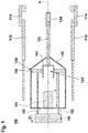
FIG. 1 shows a gas-insulatedcircuit breaker 100. The gas-insulatedcircuit breaker 100 includes housing defining a gas volume for a dielectric gas. The gas-insulatedcircuit breaker 100 can be a high-voltage circuit breaker. In the context of the present disclosure, "high voltage", such in high-voltage circuit breaker, can be understood as a voltage of at least 1 kV, in particular more than 50 kV. Accordingly, a high-voltage circuit breaker can be circuit breaker that is rated for a nominal voltage of at least 1 kV, in particular more than 50 kV. - Further, the gas-insulated
circuit breaker 100 can be generator circuit breaker, Generator circuit breakers can be rated for high currents. Specifically, the generator circuit breaker can be rated for a nominal current of at least 7000 A, in particular more than 57000 A. - The gas-insulated
circuit breaker 100 includes a nominal contact system and/or an interruption contact system. The nominal contact system includes a firstnominal contact 112 and the secondnominal contact 114. The firstnominal contact 112 and the secondnominal contact 114 are electrically connectable and disconnectable relative to one another. When electrically connected, an ohmic connection between the firstnominal contact 112 and the secondnominal contact 114 is established, whereas no ohmic connection is between the firstnominal contact 112 and the secondnominal contact 114 when the disconnected. - The interruption contact with them includes a
pin 122 and/or atulip 124. Thetulip 124 corresponds to thepin 122 such that thepin 122 and thetulip 124 are electrically connectable to and disconnectable from one another. In particular, thepin 122 and thetulip 124, which can also be referred to as a first breaker contact and a second breaker contact, can be electrically connected to one another in the closed state of the gas-insulatedcircuit breaker 100 and/or can be are electrically displaced from one another by an insulation distance and thus electrically disconnected in an open state of the gas-insulatedcircuit breaker 100. - Further, at least the
pin 122 is moveable along an axis A of the gas-insulatedcircuit breaker 100 for selectively providing and breaking an electrical connection with thetulip 124. In the context of the present disclosure, "breaking an electrical connection" can be understood as interrupting and current path. Accordingly, at least thepin 122 can be movable along the axis A for selectively moving between the close plate and the open state of the gas-insulatedcircuit breaker 100. Specifically, the axis A may run through thepin 122. - A guiding
assembly 150 is be provided. The guidingassembly 150 includes aguide sleeve 152 and/or a guidingmember 154. The guidingmember 154 is coupled to thepin 122 and configured to be moved together with thepin 122 while being glidingly guided in theguide sleeve 152 along a guiding length L. In this embodiment, the guidingmember 154 is permanently and rigidly coupled to thepin 122. Themoveable absorption element 142 is structurally connected to the guidingmember 154 in a rigid manner. - A
gas damping assembly 140 is provided. Thegas damping assembly 140 is configured to damp a breaking movement of thepin 122. SeeFig. 3 , for example. Specifically, thegas damping assembly 140 is configured to damp the breaking movement of thepin 122 by compressing the dielectric gas in anabsorber volume 125. Thegas damping assembly 140 includes at least onemoveable absorption element 142 configured to be moved at least partially along the guiding length L for compressing the dielectric gas in theabsorber volume 125. The at least onemoveable absorption element 142 is arranged radially inward of theguide sleeve 152. Theabsorber volume 125 can axially overlap with the guiding length L such as shown inFig.1 . - In the context of the present disclosure, a gas damping assembly, such as the
gas damping assembly 140, can be understood as an assembly configured for damping a movement of mechanical part by compression of a gas. Such gas damping assembly may not to be confused with a mechanical puffer unit used for pressing additional insulation/dielectric gas into the interruption zone for interrupting the electric arc. - The present disclosure provides an optimized kinematic system of a gas-insulated circuit breaker by providing a specific arrangement of the
gas damping assembly 140 and the guidingassembly 150. In particular, thegas damping assembly 140 can include parts that are arranged at rear end of thepin 122, such as themoveable absorption element 142, while being radially surrounded by a parts of the guidingassembly 150, such as theguide sleeve 152. In particular, the present may provide a damping of thepin 122 by elements arranged at the rear end of thepin 122. - By the arrangement, a length along which the
pin 122 travels during disconnection, i.e. from a connected position to a position in which the movement of thepin 122 is damped out, can be reduced. That is, the piston stroke can be reduced. Further, a diameter of the element acting as a piston can be increased, e.g. as compared to the circuit breaker shown inDE102014102929A1 , allowing reaching the same damping effect by a way shorter piston stroke. - According to embodiments described herein,
drive system 180 can be provided. Thedrive system 180 can be configured to move thepin 122 and the guidingmember 154 in a first direction D1 along the axis A in order to break the electrical connection between thepin 122 and thetulip 124. Thedrive system 180 can include, e.g., an actuator for providing a driving force and transition means for transmitting the driving force provided by the actuator to thepin 122. For instance,transmission elements 182 can be provided that can be coupled to the guidingmember 154 and/or to transmit the driving force to the guidingmember 154. Thedrive system 180 is indicated inFig.1 but not shown in any offigures 2 and 3 . - According to embodiments described herein, a front guiding element 156 can be provided at a front end of the
guide sleeve 152. In the context of the present disclosure, the front end of theguide sleeve 152 may be understood as the end of theguide sleeve 152 that is arranged along the axis A towards thetulip 124. The front end of theguide sleeve 152 may also be understood as the end of theguide sleeve 152 arranged opposite to the first direction D1. For instance, the front guiding element 156 can be a guide ring. When practicing embodiments, a more reliable guidance of thepin 122 can be provided. - According to embodiments described herein, the
guide sleeve 152 can be at least partially integrated into the firstnominal contact 112 or the secondnominal contact 124. In practice, a more compact and reliable gas-insulated circuit breaker can be provided. -
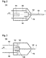
FIG. 2 shows the gas-insulatedcircuit breaker 100 in a closed state. In the closed statenominal contact 112 and the secondnominal contact 114 can be electrically connected. Further, thepin 122 and thetulip 124 can be electrically connected in the closed state.Fig. 3 shows the gas-insulatedcircuit breaker 100 in an open state. In the open statenominal contact 112 and the secondnominal contact 114 can be electrically disconnected. Further, thepin 122 and thetulip 124 can be electrically disconnected in the open state. - As shown in
FIGs. 2 and 3 , the at least onemoveable absorption element 142 can be mounted at the end of thepin 122. Further, thegas damping assembly 140 can be located along the axis A. Specifically, in the embodiment shown inFIGs. 2 and 3 , onemovable absorption element 142 can be mounted at the end of thepin 122. A fixedabsorption element 144 can be provided. The fixedabsorption element 144 can be correspondingly formed to themovable absorption element 142. - In particular one of the
movable absorption element 142 and the fixedabsorption element 144 can act as a piston. The other one of themovable absorption element 142 and the fixedabsorption element 144 can act as a cylinder. In particular, the other one of themovable absorption element 142 and the fixedabsorption element 144 can act as a cylinder for the piston, specifically the element acting as a piston. In the embodiments shown inFIGs. 2 and 3 , themovable absorption element 142 can act as a cylinder, whereas the fixedabsorption element 144 can act as a piston. However, although not shown, themovable absorption element 142 may act as a piston, whereas the fixedabsorption element 144 may act as a cylinder. Generally, the gas-insulatedcircuit breaker 100 can include the same amount ofmovable absorption elements 142 as an amount of fixedabsorption elements 144. That is, for eachmovable absorption element 142 there can be one corresponding fixedabsorption element 144. Further, in correspond ones of themovable absorption element 142 and fixedabsorption element 144, one element can act a as cylinder whereas the other element can act a as piston. - In the embodiments shown in
FIGs. 2 and 3 , the guidingmember 154 may be coupled to thepin 122 via themovable absorption element 142. Accordingly, thepin 122 can be connected to themovable absorption element 142, which in turn can be connected to the guidingmember 154. When practicing embodiments, a stable and reliable connection for guiding thepin 122 can be provided. - When the
pin 122 is removed from the closed state depicted inFIG. 2 to the open state depicted inFIG. 3 , themovable absorption element 142 is moved towards the fixedabsorption element 144. When themovable absorption element 142 approaches the fixedabsorption element 144 the dielectric gas can be compressed in theabsorber volume 125. In particular, theabsorber volume 125 can be provided by the one of themovable absorption element 142 and the fixedabsorption element 144 that acts as a piston. In the embodiments shown inFIGs. 2 and 3 , theabsorber volume 125 would accordingly be provided within themovable absorption element 142. When an embodiment, damping effect can be achieved by compressing be the dielectric gas in theabsorber volume 125. -
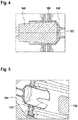
FIG. 4 shows an enlarged cross-sectional view of themovable absorption element 142 and the fixedabsorption element 144 in the closed state. As shown inFIG. 4 , themovable absorption element 142 can abut the fixedabsorption element 144 in the closed state. In particular, an end side of themovable absorption element 142 can abut against an end side of the fixedabsorption element 144 in the closed state. The end side of themovable absorption element 142 and/or the fixedabsorption element 144 can be understood as the end of the piston stroke. Generally, the end of the piston stroke can be understood as referring to the end of the separation movement and may correspond to the open state. - According to embodiments described herein, the element acting as a
cylinder piston movable absorption element 142 and fixedabsorption element 144 acting as a cylinder for the other one of themovable absorption element 142 and fixedabsorption element 144 acting as a piston can have a conical cross-section having its smallest diameter at an end of the piston stroke. Accordingly, when themovable absorption element 142 acts as a cylinder for the fixedabsorption element 144 acting as a piston, as it is shown inFIGs. 2 and 3 , themovable absorption element 142 can have a conical cross-section having its smallest diameter at an end of the piston stroke. That is, themovable absorption element 142 can have its smallest diameter at its end side. Alternatively, when the fixedabsorption element 144 acts as a cylinder for themoveable absorption element 142 acting as a piston, the fixedabsorption element 144 can have a conical cross-section having its smallest diameter at an end of the piston stroke. That is, the fixedabsorption element 144 can have its smallest diameter at its end side. - Alternatively or additionally, the element acting as a
piston movable absorption element 142 and fixedabsorption element 144 acting as a piston can have a conical cross-section having its smallest diameter at an end of the piston stroke. Accordingly, when themovable absorption element 142 acts as a cylinder for the fixedabsorption element 144 acting as a piston, as it is shown inFIGs. 2 and 3 , the fixedabsorption element 144 can have a conical cross-section having its smallest diameter at an end of the piston stroke. That is, the fixedabsorption element 144 can have its smallest diameter at its end side. Alternatively, when the fixedabsorption element 144 acts as a cylinder for themoveable absorption element 142 acting as a piston, themoveable absorption element 142 can have a conical cross-section having its smallest diameter at an end of the piston stroke. That is, themoveable absorption element 142 can have its smallest diameter at its end side. -
FIG. 5 shows an enlarged cross-sectional view of themovable absorption element 142 and the fixedabsorption element 144 in state having a distance between themovable absorption element 142 and the fixedabsorption element 144. According to embodiments described herein, the element acting as acylinder piston piston movable absorption element 142 and fixedabsorption element 144 acting as a cylinder for the other one of themovable absorption element 142 and fixedabsorption element 144 acting as a piston can have at least one cut-out 145 for allowing an easier escape of the trapped gas before the element acting as apiston - Accordingly, when the
movable absorption element 142 acts as a cylinder for the fixedabsorption element 144 acting as a piston, as it is shown inFIGs. 2 and 3 , themovable absorption element 142 can have at least one cut-out 145 for allowing an easier escape of the trapped gas before themovable absorption element 142 reaches its end position. Alternatively, when the fixedabsorption element 144 acts as a cylinder for themoveable absorption element 142 acting as a piston, the fixedabsorption element 144 can have at least one cut-out 145 for allowing an easier escape of the trapped gas before themovable absorption element 142 reaches its end position. Further, the end position can be considered as the position shown inFIG. 4 . When practicing embodiments, a further design freedom can be obtained in adjusting a damping performance. - According to embodiments described herein, no sealing element can be provided in between elements acting as a
piston cylinder piston piston cylinder piston piston cylinder piston piston cylinder piston - According to embodiments described herein, the elements acting as a
piston cylinder piston pin 122. Specifically, the at least onemovable absorption element 142 and/or the at least onefixed absorption element 144 can have a larger diameter as thepin 122. When practicing embodiments, the piston stroke can be reduced while obtaining a high damping effect. Further, at least one of the at least onemovable absorption element 142 and/or at least one of the at least onefixed absorption element 144 can have a larger diameter as thepin 122, whereas other of the at least onemovable absorption element 142 and/or other of the at least onefixed absorption element 144 can have an equal or smaller diameter as thepin 122. -
FIGs. 6 to 8 show a gas-insulatedcircuit breaker 100 according to further embodiments. While features described with respect to the foregoing embodiments can be applied to the embodiments shown inFIGs. 6 to 8 , thegas damping assembly 140 can be located radially offset from the axis A in the embodiments shown inFIGs. 6 to 8 . In particular, features that are described with respect to onemoveable absorption element 142 or one fixedabsorption element 144 can apply for more than one or allmoveable absorption elements 142 and fixedabsorption elements 144, respectively, in the gas-insulatedcircuit breaker 100. In the same manner, because the public works with respect to more than onemoveable absorption element 142 or more than one fixedabsorption element 144 can apply for one or allmoveable absorption elements 142 and fixedabsorption elements 144, respectively, in the gas-insulatedcircuit breaker 100. -
Fig. 6 shows the gas-insulatedcircuit breaker 100 in the closed state.Fig. 7 shows the gas-insulated circuit breaker 100 a state when the damping is initiated.Fig. 7 shows the gas-insulatedcircuit breaker 100 in the open state, specifically when damping has occurred. - According to embodiments, the
gas damping assembly 140 can include at least twomoveable absorption elements fixed absorption elements moveable absorption elements moveable absorption elements fixed absorption elements moveable absorption elements member 154. In particular, a higher damping effect can be obtained by providing more moveable absorption elements and fixed absorption elements. In practice, the piston stroke can be reduced by providing a greater amount of moveable absorption elements and fixed absorption elements. When practicing embodiments, a compact gas-insulated circuit breaker can be provided. - The damping effect may be further tuned or adjusted in that the element acting as a
cylinder piston Fig. 5 for allowing an easier escape of the trapped gas before the element acting as apiston - Further, a
transmission element 182 driven by the drive system (180) - not shown in any offigures 7 and8 - can be provided that can be coupled to the guidingmember 154 and/or to transmit the driving force to the guidingmember 154. Specifically, thetransmission element 182 can be arranged at the axis A behind thepin 122. - Furthermore, as shown in
FIGs. 6 to 8 , the elements acting as apiston cylinder moveable absorption elements FIGs. 6 to 8 , the at least twomoveable absorption elements fixed absorption elements fixed absorption elements fixed absorption elements moveable absorption elements piston cylinder absorber volume 125 in which the dielectric gas is compressed can be increased. - Alternatively, as shown in
FIGs. 2 and 3 , the elements acting as a piston can have a closed side facing the elements acting as a cylinder. Accordingly, when the at least twomoveable absorption elements moveable absorption elements fixed absorption elements fixed absorption elements fixed absorption elements moveable absorption elements piston cylinder absorber volume 125 in which the dielectric gas is compressed can be reduced. In practice, a further degree of freedom can be provided. - According to embodiments described herein, the gas-insulated
circuit breaker 100 can further include a network interface for connecting the gas-insulatedcircuit breaker 100 to a data network, in particular a global data network. The data network can be a TCP/IP network such as Internet. The gas-insulatedcircuit breaker 100 can be operatively connected to the network interface for carrying out commands received from the data network. The commands can include a control command for controlling the device to carry out a task such as disconnecting or connecting the gas-insulatedcircuit breaker 100. In particular, the commands can include control command for controlling the movement of thepin 122. In this case, the gas-insulatedcircuit breaker 100 can be configured for carrying out the task in response to the control command. Further, the commands can include a status request. In this case, the gas-insulatedcircuit breaker 100 can be configured for sending a status information to the network interface, and the network interface can be adapted for sending the status information over the network in response to the status request. The commands can include an update command including update data. In this case, the gas-insulatedcircuit breaker 100 can be adapted for initiating an update in response to the update command and using the update data. -
Fig. 9 shows a flowchart of amethod 300 for breaking an electrical connection of a gas-insulatedcircuit breaker 100. Inblock 310, a gas-insulatedcircuit breaker 100 can be provided. The gas-insulatedcircuit breaker 100 can have a nominal contact system with a firstnominal contact 112 and a secondnominal contact 114 that are electrically connectable and disconnectable relative to one another, and an interruption contact system with apin 122 and atulip 124 corresponding to thepin 122 such that they are electrically connectable to and disconnectable from one another. In particular, the gas-insulatedcircuit breaker 100 can correspond to embodiments described herein. - In
block 320, thepin 122 can be moved in a first direction D1 along an axis A of the gas-insulatedcircuit breaker 100 - In
block 330, thepin 122 can be guided by a guidingassembly 150. The guiding assembly can include aguide sleeve 152 and a guidingmember 154 of the gas-insulatedcircuit breaker 100. The guidingmember 154 can be coupled to thepin 122 and configured to be moved together with thepin 122 while being glidingly guided in theguide sleeve 152 along a guiding length L. - In
block 340, an electrical connection of the gas-insulatedcircuit breaker 100 can be broken. - In
block 350, the movement of thepin 122 can be damped using agas damping assembly 140. Thegas damping assembly 140 can be configured to damp a breaking movement of thepin 122 by compressing anabsorber volume 125 and having at least onemoveable absorption element 142 configured to be moved at least partially along the guiding length L for compressing theabsorber volume 125. The at least onemoveable absorption element 142 can be arranged radially inward of theguide sleeve 152. Theabsorber volume 125 can axially overlap with the guiding length L. - While the foregoing is directed to embodiments of the disclosure, other and further embodiments of the disclosure may be devised without departing from the basic scope thereof, and the scope thereof is determined by the claims that follow.
Claims (15)
- A gas-insulated circuit breaker (100) comprising:a housing defining a gas volume for a dielectric gas;a nominal contact system with a first nominal contact (112) and a second nominal contact (114) that are electrically connectable and disconnectable relative to one another, and an interruption contact system with a pin (122) and a tulip (124) corresponding to the pin (122) such that they are electrically connectable to and disconnectable from one another,wherein at least the pin (122) is moveable along an axis (A) of the gas-insulated circuit breaker (100) for selectively providing and breaking an electrical connection with the tulip (124);a guiding assembly (150) including a guide sleeve (152) and a guiding member (154), wherein the guiding member (154) is coupled to the pin (122) and configured to be moved together with the pin (122) while being glidingly guided in the guide sleeve (152) along a guiding length (L); anda gas damping assembly (140) configured to damp a breaking movement of the pin (122) by compressing the dielectric gas in an absorber volume (125) and having at least one moveable absorption element (142) configured to be moved at least partially along the guiding length (L) for compressing the dielectric gas in the absorber volume (125), characterized in that the absorber volume (125) and the at least one moveable absorption element (142) are arranged radially inward of the guide sleeve (152).
- The gas-insulated circuit breaker (100) according to claim 1, wherein the at least one moveable absorption element (142) is mounted at the end of the pin (122) such that the gas damping assembly (140) is located along the axis (A).
- The gas-insulated circuit breaker (100) according to claim 1 or 2, further comprising at least one moveable absorption element (142) that is fastened to the guiding member (154), and at least one fixed absorption element (144) formed correspondingly to the at least one moveable absorption element (142) such that the at least one moveable absorption element (142) acts as a cylinder whereas the at least one fixed absorption element (144) acts as a piston running in that cylinder or vice versa.
- The gas-insulated circuit breaker (100) according to claim 1, wherein the gas damping assembly (140) is located radially offset from the axis (A).
- The gas-insulated circuit breaker (100) according to claim 4, wherein the gas damping assembly (140) includes at least two moveable absorption elements (142a, 142b) and at least two fixed absorption elements (144a, 144b) formed correspondingly to the at least two moveable absorption elements (142a, 142b), wherein the at least two moveable absorption elements (142a, 142b) and the at least two fixed absorption elements (144a, 144b) are arranged symmetrically to one another with respect to the axis (A) such that the at least two fixed absorption elements (144a, 144b) act as a cylinder whereas the at least two moveable absorption elements (142a, 142b) act as a piston each running in that cylinder or vice versa.
- The gas-insulated circuit breaker (100) according to any one of claims 1 to 5, wherein the guide sleeve (152) is at least partially integrated into the first nominal contact (112) or the second nominal contact (114).
- The gas-insulated circuit breaker (100) according to claim 3 or 5, wherein no sealing element is provided in between absorption elements acting as a piston (144, 142, 142a, 142b) and absorption elements acting as a cylinder (142, 144, 144a, 144b) for the piston (144, 142, 142a, 142b).
- The gas-insulated circuit breaker (100) according to claim 3 or 5, wherein the absorption element acting as a cylinder (144, 142) for the absorption element acting as a piston (142, 144) has a conical cross-section having its smallest diameter at an end of the piston stroke.
- The gas-insulated circuit breaker (100) according to claim 3 or 5, wherein the absorption element acting as a cylinder (144, 142) for the absorption element acting as a piston (142, 144) has at least one cut-out (145) for allowing an easier escape of the trapped gas before the piston reaches its end position.
- The gas-insulated circuit breaker (100) according to claim 3 or 5, wherein at least one fixed absorption element (144, 144a, 144b) is fixed relative to the guide sleeve (152).
- The gas-insulated circuit breaker (100) according to any one of claims 1 to 10, further comprising a drive system (180) configured to move the pin (122) and the guiding member (154) along the axis (A), and
wherein the drive system (180) is coupled to the guiding member (154) by at least one transmission element (182) that is extending into the interior of the guide sleeve (152) such that the pin (122) is driven by the guiding member (154). - The gas-insulated circuit breaker (100) according to claim 11, wherein the damping assembly (140) is arranged at least partially alongside the at least one transmission element (182) with respect to the axis (A) of the gas-insulated circuit breaker (100).
- The gas-insulated circuit breaker (100) according to any one of claims 1 to 12, wherein the gas-insulated circuit breaker (100) is a high-voltage circuit breaker.
- The gas-insulated circuit breaker (100) according to any one of claims 1 to 12, wherein the gas-insulated circuit breaker (100) is a generator circuit breaker.
- A method for breaking an electrical connection of a gas-insulated circuit breaker (100), comprising:providing a gas-insulated circuit breaker (100) having a nominal contact system with a first nominal contact (112) and a second nominal contact (114) that are electrically connectable and disconnectable relative to one another, and an interruption contact system with a pin (122) and a tulip (124) corresponding to the pin (122) such that they are electrically connectable to and disconnectable from one another;moving the pin (122) in a first direction (D1) along an axis (A) of the gas-insulated circuit breaker (100);guiding the pin (122) by a guiding assembly (150) including a guide sleeve (152) and a guiding member (154) of the gas-insulated circuit breaker (100), wherein the guiding member (154) is coupled to the pin (122) and configured to be moved together with the pin (122) while being glidingly guided in the guide sleeve (152) along a guiding length (L);breaking an electrical connection of the gas-insulated circuit breaker (100); anddamping the movement of the pin (122) using a gas damping assembly (140) configured to damp a breaking movement of the pin (122) by compressing an absorber volume (125) and having at least one moveable absorption element (142) configured to be moved at least partially along the guiding length (L) for compressing the absorber volume (125), characterized in that the absorber volume (125) and the at least one moveable absorption element (142) is arranged radially inward of the guide sleeve (152).
Applications Claiming Priority (1)
| Application Number | Priority Date | Filing Date | Title |
|---|---|---|---|
| LU100163 | 2017-04-07 |
Publications (2)
| Publication Number | Publication Date |
|---|---|
| EP3385969A1 EP3385969A1 (en) | 2018-10-10 |
| EP3385969B1 true EP3385969B1 (en) | 2021-10-20 |
Family
ID=59009737
Family Applications (1)
| Application Number | Title | Priority Date | Filing Date |
|---|---|---|---|
| EP18164863.5A Active EP3385969B1 (en) | 2017-04-07 | 2018-03-29 | Gas-insulated circuit breaker and a method for breaking an electrical connection |
Country Status (3)
| Country | Link |
|---|---|
| US (1) | US10535480B2 (en) |
| EP (1) | EP3385969B1 (en) |
| CN (1) | CN108695105B (en) |
Family Cites Families (19)
| Publication number | Priority date | Publication date | Assignee | Title |
|---|---|---|---|---|
| FR876971A (en) * | 1941-06-18 | 1942-11-24 | Delle Atel Const Electr | Improvements to self-blowing electric switches |
| DE838008C (en) * | 1951-04-03 | 1952-05-05 | Calor-Emag Elektrizitäts-Aktiengesellschaft, Ratingen bei Düsseldorf | HYDRAULIC SWITCH-OFF DAMPING |
| NL135712C (en) * | 1969-03-14 | |||
| SE424483B (en) * | 1980-11-27 | 1982-07-19 | Asea Ab | DEMPDON FOR ELECTRIC SWITCHES |
| DE3104411A1 (en) * | 1981-02-09 | 1982-08-26 | Licentia Patent-Verwaltungs-Gmbh, 6000 Frankfurt | Electrical compression switch |
| JPS57185146U (en) * | 1981-05-19 | 1982-11-24 | ||
| JPS6039722A (en) * | 1983-08-12 | 1985-03-01 | 株式会社日立製作所 | Brake device of breaker |
| US5045651A (en) * | 1989-02-08 | 1991-09-03 | Hitachi, Ltd. | Switch |
| JPH05114337A (en) * | 1991-10-23 | 1993-05-07 | Fuji Electric Co Ltd | Switch |
| DE10006167B4 (en) * | 2000-02-11 | 2009-07-23 | Abb Schweiz Ag | breakers |
| EP1719141A1 (en) | 2004-01-30 | 2006-11-08 | ABB Technology Ltd | Condition monitor for an electrical distribution device |
| JP5153255B2 (en) * | 2007-08-13 | 2013-02-27 | 三菱電機株式会社 | Ground switchgear |
| EP2309526B1 (en) * | 2009-10-08 | 2012-10-03 | ABB Technology AG | Voltage switch with parallel nominal current paths |
| US9165732B2 (en) * | 2011-08-30 | 2015-10-20 | Mitsubishi Electric Corporation | Gas circuit breaker |
| JP5865670B2 (en) * | 2011-10-24 | 2016-02-17 | 株式会社東芝 | Gas circuit breaker |
| JP6157824B2 (en) * | 2012-09-28 | 2017-07-05 | 株式会社東芝 | Gas circuit breaker |
| US20140175061A1 (en) * | 2012-12-20 | 2014-06-26 | Abb Technology Ag | Electrical switching device with a triple motion contact arrangement |
| DE102014102929A1 (en) * | 2014-03-05 | 2015-09-10 | Abb Technology Ag | Gas damper for a high voltage switch |
| CN107077988B (en) * | 2014-06-02 | 2019-07-16 | Abb瑞士股份有限公司 | High voltage puffer circuit breaker and breaker unit with this puffer circuit breaker |
-
2018
- 2018-03-29 EP EP18164863.5A patent/EP3385969B1/en active Active
- 2018-04-04 CN CN201810301514.9A patent/CN108695105B/en active Active
- 2018-04-09 US US15/948,561 patent/US10535480B2/en active Active
Also Published As
| Publication number | Publication date |
|---|---|
| EP3385969A1 (en) | 2018-10-10 |
| US20180294116A1 (en) | 2018-10-11 |
| CN108695105A (en) | 2018-10-23 |
| US10535480B2 (en) | 2020-01-14 |
| CN108695105B (en) | 2022-06-07 |
Similar Documents
| Publication | Publication Date | Title |
|---|---|---|
| US6593538B2 (en) | High-voltage interrupter device having combined vacuum and gas interruption | |
| US5239150A (en) | Medium voltage circuit breaker with operating mechanism providing reduced operating energy | |
| US5478980A (en) | Compact low force dead tank circuit breaker interrupter | |
| JP2009048789A (en) | Ground switchgear | |
| US20130284703A1 (en) | Gas circuit breaker | |
| KR20060063720A (en) | Current breaking method of puffer type gas circuit breaker and puffer type gas circuit breaker | |
| WO2012155952A1 (en) | Double-motion gas insulated type circuit breaker | |
| JP5236902B2 (en) | Operating mechanism of AC circuit breaker by cylindrical cam | |
| KR101919125B1 (en) | Gas insulated switch device of high voltage distributer | |
| CN113035636A (en) | Switchgear and distribution equipment | |
| US5837953A (en) | DC circuit breaking device | |
| EP2097915B1 (en) | High-voltage disconnecting circuit breaker and method of operating the same | |
| US5841614A (en) | High voltage circuit breaker with insertion of resistance on closure | |
| JP5175322B2 (en) | Circuit breaker with parallel rated current path | |
| EP3385969B1 (en) | Gas-insulated circuit breaker and a method for breaking an electrical connection | |
| KR101678000B1 (en) | Dual motion structure of circuit breaker for gis | |
| US5742017A (en) | Circuit-breaker provided with a closure resistance having an insertion assembly | |
| EP2752864B1 (en) | Gas insulated switchgear | |
| US4996399A (en) | High or medium tension circuit breaker | |
| RU2157016C2 (en) | Switch with on resistance | |
| RU2247439C1 (en) | High-voltage vacuum load switch | |
| KR100344281B1 (en) | Bidirectional operation type gas circuit breaker | |
| JP2015082368A (en) | Gas circuit breaker | |
| EP4432326A1 (en) | High voltage circuit-breaker | |
| JPS6210824A (en) | Buffer type gas breaker |
Legal Events
| Date | Code | Title | Description |
|---|---|---|---|
| PUAI | Public reference made under article 153(3) epc to a published international application that has entered the european phase |
Free format text: ORIGINAL CODE: 0009012 |
|
| STAA | Information on the status of an ep patent application or granted ep patent |
Free format text: STATUS: THE APPLICATION HAS BEEN PUBLISHED |
|
| AK | Designated contracting states |
Kind code of ref document: A1 Designated state(s): AL AT BE BG CH CY CZ DE DK EE ES FI FR GB GR HR HU IE IS IT LI LT LU LV MC MK MT NL NO PL PT RO RS SE SI SK SM TR |
|
| AX | Request for extension of the european patent |
Extension state: BA ME |
|
| STAA | Information on the status of an ep patent application or granted ep patent |
Free format text: STATUS: REQUEST FOR EXAMINATION WAS MADE |
|
| 17P | Request for examination filed |
Effective date: 20190410 |
|
| RBV | Designated contracting states (corrected) |
Designated state(s): AL AT BE BG CH CY CZ DE DK EE ES FI FR GB GR HR HU IE IS IT LI LT LU LV MC MK MT NL NO PL PT RO RS SE SI SK SM TR |
|
| RAP1 | Party data changed (applicant data changed or rights of an application transferred) |
Owner name: ABB POWER GRIDS SWITZERLAND AG |
|
| GRAP | Despatch of communication of intention to grant a patent |
Free format text: ORIGINAL CODE: EPIDOSNIGR1 |
|
| STAA | Information on the status of an ep patent application or granted ep patent |
Free format text: STATUS: GRANT OF PATENT IS INTENDED |
|
| INTG | Intention to grant announced |
Effective date: 20210510 |
|
| GRAS | Grant fee paid |
Free format text: ORIGINAL CODE: EPIDOSNIGR3 |
|
| GRAA | (expected) grant |
Free format text: ORIGINAL CODE: 0009210 |
|
| STAA | Information on the status of an ep patent application or granted ep patent |
Free format text: STATUS: THE PATENT HAS BEEN GRANTED |
|
| AK | Designated contracting states |
Kind code of ref document: B1 Designated state(s): AL AT BE BG CH CY CZ DE DK EE ES FI FR GB GR HR HU IE IS IT LI LT LU LV MC MK MT NL NO PL PT RO RS SE SI SK SM TR |
|
| REG | Reference to a national code |
Ref country code: GB Ref legal event code: FG4D |
|
| REG | Reference to a national code |
Ref country code: CH Ref legal event code: EP |
|
| REG | Reference to a national code |
Ref country code: DE Ref legal event code: R096 Ref document number: 602018025183 Country of ref document: DE |
|
| REG | Reference to a national code |
Ref country code: IE Ref legal event code: FG4D |
|
| REG | Reference to a national code |
Ref country code: AT Ref legal event code: REF Ref document number: 1440617 Country of ref document: AT Kind code of ref document: T Effective date: 20211115 |
|
| RAP4 | Party data changed (patent owner data changed or rights of a patent transferred) |
Owner name: HITACHI ENERGY SWITZERLAND AG |
|
| REG | Reference to a national code |
Ref country code: LT Ref legal event code: MG9D |
|
| REG | Reference to a national code |
Ref country code: NL Ref legal event code: MP Effective date: 20211020 |
|
| REG | Reference to a national code |
Ref country code: AT Ref legal event code: MK05 Ref document number: 1440617 Country of ref document: AT Kind code of ref document: T Effective date: 20211020 |
|
| PG25 | Lapsed in a contracting state [announced via postgrant information from national office to epo] |
Ref country code: RS Free format text: LAPSE BECAUSE OF FAILURE TO SUBMIT A TRANSLATION OF THE DESCRIPTION OR TO PAY THE FEE WITHIN THE PRESCRIBED TIME-LIMIT Effective date: 20211020 Ref country code: LT Free format text: LAPSE BECAUSE OF FAILURE TO SUBMIT A TRANSLATION OF THE DESCRIPTION OR TO PAY THE FEE WITHIN THE PRESCRIBED TIME-LIMIT Effective date: 20211020 Ref country code: FI Free format text: LAPSE BECAUSE OF FAILURE TO SUBMIT A TRANSLATION OF THE DESCRIPTION OR TO PAY THE FEE WITHIN THE PRESCRIBED TIME-LIMIT Effective date: 20211020 Ref country code: BG Free format text: LAPSE BECAUSE OF FAILURE TO SUBMIT A TRANSLATION OF THE DESCRIPTION OR TO PAY THE FEE WITHIN THE PRESCRIBED TIME-LIMIT Effective date: 20220120 Ref country code: AT Free format text: LAPSE BECAUSE OF FAILURE TO SUBMIT A TRANSLATION OF THE DESCRIPTION OR TO PAY THE FEE WITHIN THE PRESCRIBED TIME-LIMIT Effective date: 20211020 |
|
| PG25 | Lapsed in a contracting state [announced via postgrant information from national office to epo] |
Ref country code: IS Free format text: LAPSE BECAUSE OF FAILURE TO SUBMIT A TRANSLATION OF THE DESCRIPTION OR TO PAY THE FEE WITHIN THE PRESCRIBED TIME-LIMIT Effective date: 20220220 Ref country code: SE Free format text: LAPSE BECAUSE OF FAILURE TO SUBMIT A TRANSLATION OF THE DESCRIPTION OR TO PAY THE FEE WITHIN THE PRESCRIBED TIME-LIMIT Effective date: 20211020 Ref country code: PT Free format text: LAPSE BECAUSE OF FAILURE TO SUBMIT A TRANSLATION OF THE DESCRIPTION OR TO PAY THE FEE WITHIN THE PRESCRIBED TIME-LIMIT Effective date: 20220221 Ref country code: PL Free format text: LAPSE BECAUSE OF FAILURE TO SUBMIT A TRANSLATION OF THE DESCRIPTION OR TO PAY THE FEE WITHIN THE PRESCRIBED TIME-LIMIT Effective date: 20211020 Ref country code: NO Free format text: LAPSE BECAUSE OF FAILURE TO SUBMIT A TRANSLATION OF THE DESCRIPTION OR TO PAY THE FEE WITHIN THE PRESCRIBED TIME-LIMIT Effective date: 20220120 Ref country code: NL Free format text: LAPSE BECAUSE OF FAILURE TO SUBMIT A TRANSLATION OF THE DESCRIPTION OR TO PAY THE FEE WITHIN THE PRESCRIBED TIME-LIMIT Effective date: 20211020 Ref country code: LV Free format text: LAPSE BECAUSE OF FAILURE TO SUBMIT A TRANSLATION OF THE DESCRIPTION OR TO PAY THE FEE WITHIN THE PRESCRIBED TIME-LIMIT Effective date: 20211020 Ref country code: HR Free format text: LAPSE BECAUSE OF FAILURE TO SUBMIT A TRANSLATION OF THE DESCRIPTION OR TO PAY THE FEE WITHIN THE PRESCRIBED TIME-LIMIT Effective date: 20211020 Ref country code: GR Free format text: LAPSE BECAUSE OF FAILURE TO SUBMIT A TRANSLATION OF THE DESCRIPTION OR TO PAY THE FEE WITHIN THE PRESCRIBED TIME-LIMIT Effective date: 20220121 Ref country code: ES Free format text: LAPSE BECAUSE OF FAILURE TO SUBMIT A TRANSLATION OF THE DESCRIPTION OR TO PAY THE FEE WITHIN THE PRESCRIBED TIME-LIMIT Effective date: 20211020 |
|
| REG | Reference to a national code |
Ref country code: DE Ref legal event code: R081 Ref document number: 602018025183 Country of ref document: DE Owner name: HITACHI ENERGY SWITZERLAND AG, CH Free format text: FORMER OWNER: ABB POWER GRIDS SWITZERLAND AG, BADEN, CH Ref country code: DE Ref legal event code: R081 Ref document number: 602018025183 Country of ref document: DE Owner name: HITACHI ENERGY LTD, CH Free format text: FORMER OWNER: ABB POWER GRIDS SWITZERLAND AG, BADEN, CH |
|
| REG | Reference to a national code |
Ref country code: DE Ref legal event code: R097 Ref document number: 602018025183 Country of ref document: DE |
|
| PG25 | Lapsed in a contracting state [announced via postgrant information from national office to epo] |
Ref country code: SM Free format text: LAPSE BECAUSE OF FAILURE TO SUBMIT A TRANSLATION OF THE DESCRIPTION OR TO PAY THE FEE WITHIN THE PRESCRIBED TIME-LIMIT Effective date: 20211020 Ref country code: SK Free format text: LAPSE BECAUSE OF FAILURE TO SUBMIT A TRANSLATION OF THE DESCRIPTION OR TO PAY THE FEE WITHIN THE PRESCRIBED TIME-LIMIT Effective date: 20211020 Ref country code: RO Free format text: LAPSE BECAUSE OF FAILURE TO SUBMIT A TRANSLATION OF THE DESCRIPTION OR TO PAY THE FEE WITHIN THE PRESCRIBED TIME-LIMIT Effective date: 20211020 Ref country code: EE Free format text: LAPSE BECAUSE OF FAILURE TO SUBMIT A TRANSLATION OF THE DESCRIPTION OR TO PAY THE FEE WITHIN THE PRESCRIBED TIME-LIMIT Effective date: 20211020 Ref country code: DK Free format text: LAPSE BECAUSE OF FAILURE TO SUBMIT A TRANSLATION OF THE DESCRIPTION OR TO PAY THE FEE WITHIN THE PRESCRIBED TIME-LIMIT Effective date: 20211020 Ref country code: CZ Free format text: LAPSE BECAUSE OF FAILURE TO SUBMIT A TRANSLATION OF THE DESCRIPTION OR TO PAY THE FEE WITHIN THE PRESCRIBED TIME-LIMIT Effective date: 20211020 |
|
| PLBE | No opposition filed within time limit |
Free format text: ORIGINAL CODE: 0009261 |
|
| STAA | Information on the status of an ep patent application or granted ep patent |
Free format text: STATUS: NO OPPOSITION FILED WITHIN TIME LIMIT |
|
| 26N | No opposition filed |
Effective date: 20220721 |
|
| PG25 | Lapsed in a contracting state [announced via postgrant information from national office to epo] |
Ref country code: MC Free format text: LAPSE BECAUSE OF FAILURE TO SUBMIT A TRANSLATION OF THE DESCRIPTION OR TO PAY THE FEE WITHIN THE PRESCRIBED TIME-LIMIT Effective date: 20211020 Ref country code: AL Free format text: LAPSE BECAUSE OF FAILURE TO SUBMIT A TRANSLATION OF THE DESCRIPTION OR TO PAY THE FEE WITHIN THE PRESCRIBED TIME-LIMIT Effective date: 20211020 |
|
| REG | Reference to a national code |
Ref country code: CH Ref legal event code: PL |
|
| GBPC | Gb: european patent ceased through non-payment of renewal fee |
Effective date: 20220329 |
|
| PG25 | Lapsed in a contracting state [announced via postgrant information from national office to epo] |
Ref country code: SI Free format text: LAPSE BECAUSE OF FAILURE TO SUBMIT A TRANSLATION OF THE DESCRIPTION OR TO PAY THE FEE WITHIN THE PRESCRIBED TIME-LIMIT Effective date: 20211020 |
|
| REG | Reference to a national code |
Ref country code: BE Ref legal event code: MM Effective date: 20220331 |
|
| PG25 | Lapsed in a contracting state [announced via postgrant information from national office to epo] |
Ref country code: LU Free format text: LAPSE BECAUSE OF NON-PAYMENT OF DUE FEES Effective date: 20220329 Ref country code: LI Free format text: LAPSE BECAUSE OF NON-PAYMENT OF DUE FEES Effective date: 20220331 Ref country code: IE Free format text: LAPSE BECAUSE OF NON-PAYMENT OF DUE FEES Effective date: 20220329 Ref country code: GB Free format text: LAPSE BECAUSE OF NON-PAYMENT OF DUE FEES Effective date: 20220329 Ref country code: CH Free format text: LAPSE BECAUSE OF NON-PAYMENT OF DUE FEES Effective date: 20220331 |
|
| PG25 | Lapsed in a contracting state [announced via postgrant information from national office to epo] |
Ref country code: BE Free format text: LAPSE BECAUSE OF NON-PAYMENT OF DUE FEES Effective date: 20220331 |
|
| PG25 | Lapsed in a contracting state [announced via postgrant information from national office to epo] |
Ref country code: IT Free format text: LAPSE BECAUSE OF FAILURE TO SUBMIT A TRANSLATION OF THE DESCRIPTION OR TO PAY THE FEE WITHIN THE PRESCRIBED TIME-LIMIT Effective date: 20211020 |
|
| P01 | Opt-out of the competence of the unified patent court (upc) registered |
Effective date: 20230527 |
|
| PG25 | Lapsed in a contracting state [announced via postgrant information from national office to epo] |
Ref country code: HU Free format text: LAPSE BECAUSE OF FAILURE TO SUBMIT A TRANSLATION OF THE DESCRIPTION OR TO PAY THE FEE WITHIN THE PRESCRIBED TIME-LIMIT; INVALID AB INITIO Effective date: 20180329 |
|
| REG | Reference to a national code |
Ref country code: DE Ref legal event code: R082 Ref document number: 602018025183 Country of ref document: DE Representative=s name: DENNEMEYER & ASSOCIATES RECHTSANWALTSGESELLSCH, DE Ref country code: DE Ref legal event code: R082 Ref document number: 602018025183 Country of ref document: DE Representative=s name: DENNEMEYER & ASSOCIATES S.A., DE Ref country code: DE Ref legal event code: R081 Ref document number: 602018025183 Country of ref document: DE Owner name: HITACHI ENERGY LTD, CH Free format text: FORMER OWNER: HITACHI ENERGY SWITZERLAND AG, BADEN, CH |
|
| PG25 | Lapsed in a contracting state [announced via postgrant information from national office to epo] |
Ref country code: MK Free format text: LAPSE BECAUSE OF FAILURE TO SUBMIT A TRANSLATION OF THE DESCRIPTION OR TO PAY THE FEE WITHIN THE PRESCRIBED TIME-LIMIT Effective date: 20211020 Ref country code: CY Free format text: LAPSE BECAUSE OF FAILURE TO SUBMIT A TRANSLATION OF THE DESCRIPTION OR TO PAY THE FEE WITHIN THE PRESCRIBED TIME-LIMIT Effective date: 20211020 |
|
| PG25 | Lapsed in a contracting state [announced via postgrant information from national office to epo] |
Ref country code: TR Free format text: LAPSE BECAUSE OF FAILURE TO SUBMIT A TRANSLATION OF THE DESCRIPTION OR TO PAY THE FEE WITHIN THE PRESCRIBED TIME-LIMIT Effective date: 20211020 |
|
| PG25 | Lapsed in a contracting state [announced via postgrant information from national office to epo] |
Ref country code: MT Free format text: LAPSE BECAUSE OF FAILURE TO SUBMIT A TRANSLATION OF THE DESCRIPTION OR TO PAY THE FEE WITHIN THE PRESCRIBED TIME-LIMIT Effective date: 20211020 |
|
| PGFP | Annual fee paid to national office [announced via postgrant information from national office to epo] |
Ref country code: DE Payment date: 20250319 Year of fee payment: 8 |
|
| PGFP | Annual fee paid to national office [announced via postgrant information from national office to epo] |
Ref country code: FR Payment date: 20250326 Year of fee payment: 8 |
|
| REG | Reference to a national code |
Ref country code: DE Ref legal event code: R082 Ref document number: 602018025183 Country of ref document: DE Representative=s name: DENNEMEYER & ASSOCIATES RECHTSANWALTSGESELLSCH, DE |