RU2157016C2 - Switch with on resistance - Google Patents
Switch with on resistance Download PDFInfo
- Publication number
- RU2157016C2 RU2157016C2 RU98111066/09A RU98111066A RU2157016C2 RU 2157016 C2 RU2157016 C2 RU 2157016C2 RU 98111066/09 A RU98111066/09 A RU 98111066/09A RU 98111066 A RU98111066 A RU 98111066A RU 2157016 C2 RU2157016 C2 RU 2157016C2
- Authority
- RU
- Russia
- Prior art keywords
- arc
- contacts
- contact
- semi
- switch
- Prior art date
Links
Images
Classifications
-
- H—ELECTRICITY
- H01—ELECTRIC ELEMENTS
- H01H—ELECTRIC SWITCHES; RELAYS; SELECTORS; EMERGENCY PROTECTIVE DEVICES
- H01H33/00—High-tension or heavy-current switches with arc-extinguishing or arc-preventing means
- H01H33/02—Details
- H01H33/04—Means for extinguishing or preventing arc between current-carrying parts
- H01H33/16—Impedances connected with contacts
- H01H33/166—Impedances connected with contacts the impedance being inserted only while closing the switch
Landscapes
- Circuit Breakers (AREA)
- Arc-Extinguishing Devices That Are Switches (AREA)
- Driving Mechanisms And Operating Circuits Of Arc-Extinguishing High-Tension Switches (AREA)
- Refuge Islands, Traffic Blockers, Or Guard Fence (AREA)
- Cookers (AREA)
- Keying Circuit Devices (AREA)
Abstract
Description
Изобретение относится к выключателю, содержащему первый постоянный контакт и первый дуговой контакт, которые установлены неподвижно в корпусе, второй постоянный контакт и второй дуговой контакт, которые установлены с возможностью перемещения в корпусе в продольном направлении и предназначены для взаимодействия с первыми неподвижными контактами, а также систему включения сопротивления замыкания, вторые подвижные контакты, входящие в состав подвижной части, на которой установлено сопло дутья. The invention relates to a circuit breaker comprising a first permanent contact and a first arc contact, which are fixedly mounted in the housing, a second permanent contact and a second arc contact, which are mounted movably in the housing in the longitudinal direction and are designed to interact with the first fixed contacts, as well as a system switching resistance of the circuit, the second movable contacts that make up the movable part, on which the blast nozzle is installed.
Из FR 2657459 А1 (кл. H 01 H 33/91, 12 стр., 26.07.91) известен выключатель, содержащий первый постоянный контакт и первый дуговой контакт, которые установлены неподвижно в корпусе, второй постоянный контакт, второй дуговой контакт, которые установлены с возможностью перемещения в корпусе вдоль продольного направления и предназначены для взаимодействия с первыми, постоянным и дуговым, неподвижными контактами, а также систему включения сопротивления замыкания, причем вторые, постоянный и дуговой, подвижные контакты входят в состав подвижной части, на которой установлено сопло дутья, при этом система включения сопротивления замыкания содержит полуподвижный блок, расположенный таким образом, чтобы, при осуществлении операции замыкания, он перемещался с помощью сопла в продольном направлении. From FR 2657459 A1 (class H 01 H 33/91, 12 pages, 07.26.91) a circuit breaker is known comprising a first permanent contact and a first arc contact which are fixedly mounted in the housing, a second permanent contact, a second arc contact that are installed with the possibility of movement in the housing along the longitudinal direction and are designed to interact with the first, constant and arc, fixed contacts, as well as the system of inclusion of resistance to closure, and the second, constant and arc, moving contacts are part of the moving part, on which The blast nozzle is installed, and the closure resistance switching system comprises a semi-movable unit located so that, during the closure operation, it moves with the nozzle in the longitudinal direction.
Недостатком известного выключателя является сложная конструкция системы включения сопротивления замыкания. A disadvantage of the known switch is the complex design of the circuit resistance circuit.
Задачей настоящего изобретения является создание системы включения сопротивления замыкания для такого выключателя, которая имела бы простую конструкцию и которая позволяла бы обеспечить хорошую компактность устройства с минимальным количеством подвижных деталей. An object of the present invention is to provide a fault resistance switching system for such a switch, which would have a simple structure and which would ensure good compactness of the device with a minimum number of moving parts.
Поставленная задача решается тем, что в выключателе, содержащем первый постоянный контакт и первый дуговой контакт, которые установлены неподвижно в корпусе, второй постоянный контакт, второй дуговой контакт, которые установлены с возможностью перемещения в корпусе вдоль продольного направления и предназначены для взаимодействия с первыми, постоянным и дуговым, неподвижными контактами, а также систему включения сопротивления замыкания, причем вторые, постоянный и дуговой, подвижные контакты входят в состав подвижной части, на которой установлено сопло дутья, при этом система включения сопротивления замыкания содержит полуподвижный блок, расположенный таким образом, чтобы, при осуществлении операции замыкания, он перемещался с помощью сопла в продольном направлении, согласно изобретению на полуподвижном блоке установлен третий дуговой контакт, предназначенный для взаимодействия с четвертым дуговым неподвижным контактом, соединенным с постоянным неподвижным контактом, причем полуподвижный блок выполнен с возможностью перемещения и приближения третьего и четвертого дуговых контактов друг к другу для осуществления короткого замыкания сопротивления замыкания в то время, как первый и второй дуговые контакты соединены друг с другом, причем указанные постоянные контакты выполнены с возможностью соединения друг с другом только после того, как третий и четвертый дуговые контакты сами соединятся друг с другом. The problem is solved in that in the switch containing the first constant contact and the first arc contact, which are installed motionlessly in the housing, the second constant contact, the second arc contact, which are installed with the possibility of movement in the housing along the longitudinal direction and are designed to interact with the first, constant and arc, fixed contacts, as well as a system for switching on the resistance of the circuit, and the second, constant and arc, moving contacts are part of the moving part, on which a blast nozzle is installed, and the closure resistance switching system comprises a semi-movable block arranged so that, during the closure operation, it moves with the nozzle in the longitudinal direction, according to the invention, a third arc contact is provided on the semi-movable block, designed to interact with the fourth arc a fixed contact connected to a permanent fixed contact, and the semi-mobile unit is arranged to move and approach the third and fourth arc contacts to each other to effect a short circuit of the resistance of the short circuit while the first and second arc contacts are connected to each other, and these permanent contacts are made with the possibility of connection with each other only after the third and fourth arc contacts themselves are connected together.
В выключателе согласно изобретению полуподвижный блок может содержать конец, выполненный в форме цилиндра, который вставлен в сопло дутья, выполненное в форме тюльпана, при операции замыкания выключателя. In the circuit breaker according to the invention, the semi-movable unit may comprise an end made in the form of a cylinder, which is inserted into the blast nozzle made in the form of a tulip during the operation of closing the circuit breaker.
В выключателе согласно изобретению полуподвижный блок может быть выполнен в форме трубы и содержать пружину деформируемую при замыкании выключателя, и камеру, заполняемую газом во время операции замыкания таким образом, что при размыкании выключателя пружина прилагает возвратное усилие, которое способствует перемещению полуподвижного блока в направлении перемещения вторых подвижных контактов, причем перемещение полуподвижного блока задерживается и замедляется относительно движения вторых подвижных контактов под воздействием сжатия газа в камере. In the circuit breaker according to the invention, the semi-movable unit can be made in the form of a pipe and contain a spring deformable when the circuit breaker closes, and a chamber filled with gas during the closing operation so that when the circuit breaker opens, the spring exerts a return force that facilitates the movement of the semi-movable unit in the direction of movement of the second moving contacts, and the movement of the semi-moving unit is delayed and slowed down relative to the movement of the second movable contacts under the influence of tions in the gas chamber.
В выключателе согласно изобретению камера может содержать отверстия, калиброванные таким образом, чтобы при размыкании выключателя создавалось усилие, препятствующее возвратному усилию пружины. In the circuit breaker according to the invention, the chamber may comprise openings calibrated so that when the circuit breaker opens, a force is created which prevents the spring from returning.
В выключателе согласно изобретению сопротивление замыкания, полуподвижный блок и контакты могут быть расположены в ряд вдоль осевой линии в корпусе. In the circuit breaker according to the invention, the circuit resistance, the semi-movable unit and the contacts can be arranged in a row along the center line in the housing.
В дальнейшем подробно описан вариант выполнения выключателя согласно изобретению со ссылками на чертежи. An embodiment of a circuit breaker according to the invention is described in detail below with reference to the drawings.
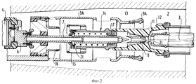
- фиг. 1 изображает схематичный вид выключателя, согласно изобретению, в полностью разомкнутом положении;
- фиг. 2 изображает схематичный вид выключателя, изображенного на фиг. 1 в первом промежуточном положении замыкания;
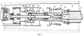
- фиг. 3 изображает схематичный вид выключателя, изображенного на фиг. 1, во втором промежуточном положении замыкания;
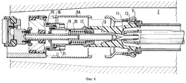
- фиг. 4 изображает схематичный вид выключателя, изображенного на фиг. 1 в полностью замкнутом положении;
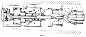
- фиг. 5 изображает схематичный вид выключателя, изображенного на фиг.1 в первом промежуточном положении размыкания;
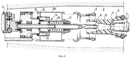
- фиг. 6 изображает очень схематичный вид выключателя, изображенного на фиг.1 во втором промежуточном положении размыкания.- FIG. 1 is a schematic view of a circuit breaker according to the invention in a fully open position;
- FIG. 2 is a schematic view of the switch of FIG. 1 in a first intermediate circuit position;
- FIG. 3 is a schematic view of the switch of FIG. 1, in the second intermediate position of the circuit;
- FIG. 4 is a schematic view of the switch of FIG. 1 in a fully closed position;
- FIG. 5 is a schematic view of the switch of FIG. 1 in a first intermediate opening position;
- FIG. 6 is a very schematic view of the switch of FIG. 1 in a second intermediate opening position.
Изображенный частично на чертежах выключатель содержит изолирующий корпус 1 цилиндрической формы, выполненный, например, из фарфора, который ограничивает внутренний объем 2, предназначенный для заполнения диэлектрическим газом, таким, как SF6 под давлением в несколько бар. The switch partially depicted in the drawings comprises a cylindrical insulating body 1 made, for example, of porcelain, which limits the
Этот выключатель является выключателем с простым движением, т.е. он выполнен только с одной подвижной частью дугового контакта и постоянного контакта и содержит систему включения сопротивления замыкания, конструкция которой позволяет контролировать простым способом продолжительность включения сопротивления при замыкании выключателя, причем это сопротивление не должно включаться при размыкании выключателя. This switch is a simple movement switch, i.e. it is made with only one movable part of the arc contact and constant contact and contains a fault resistance switching system, the design of which makes it possible to control in a simple way the resistance switching duration when the circuit breaker is closed, and this resistance should not be turned on when the circuit breaker is opened.
Сопротивление 4 замыкания состоит из набора сопротивлений, расположенных в изолирующем кронштейне 5, расположенном внутри корпуса в конце последнего. Сопротивление 4 замыкания находится в электрическом контакте с металлическим блоком 6, на котором крепится металлический стержень, расположенный в осевом направлении корпуса. Resistance 4 circuit consists of a set of resistances located in an insulating bracket 5 located inside the housing at the end of the latter. The resistance 4 of the circuit is in electrical contact with the metal block 6, on which is attached a metal rod located in the axial direction of the housing.
В варианте выполнения, изображенном на чертежах, сопротивление 4 замыкания располагается в осевом направлении в корпусе, но можно было бы предусмотреть также эксцентричное расположение этого сопротивления в корпусе, не выходя за рамки изобретения. In the embodiment shown in the drawings, the closure resistance 4 is located in the axial direction in the housing, but an eccentric arrangement of this resistance in the housing could also be provided without going beyond the scope of the invention.
Неподвижный дуговой контакт 8 расположен на свободном конце стержня 7. Неподвижный постоянный контакт 9 расположен на конце металлической трубы 9А, которая расположена вокруг стержня 7 соосно трубе. Изолирующий конус 10 предусматривается как факультативный вариант выполнения для удержания стержня 7 внутри трубы 9А. Эти два контакта 8 и 9 взаимодействуют с дуговым контактом 11 и постоянным контактом 12, который входит в выдвижную часть по оси 3 и на нем установлено сопло 13 дутья в виде тюльпана. A
Система включения сопротивления 4 замыкания содержит металлический полуподвижный блок 14, выполненный в виде трубы, который установлен с возможностью скольжения на стержне 7, т.е. по оси 3. Этот полуподвижный блок 14 электрически соединен со стержнем 7 посредством скользящих контактов 17. На нем установлен дуговой контакт 15, названный в последующем описании первым переключающим контактом, который выполнен в виде тюльпана и предназначен для взаимодействия с другим дуговым контактом 16 в виде кольца, который назван в дальнейшем описании вторым переключающим контактом, расположен внутри цилиндрической трубы 9А, и который электрически соединен с этой трубой. The inclusion system of the resistance 4 circuit contains a metal
Следует отметить, что конструкция системы включения сопротивления расположена исключительно по оси в кожухе, который может иметь относительно небольшой диаметр. It should be noted that the design of the resistance switching system is located exclusively along the axis in the casing, which may have a relatively small diameter.
Как изображено на чертежах, полуподвижный блок 14 имеет один конец, который расположен напротив сопла 13 дутья дугогасительной камеры в виде конуса, который выполнен таким образом, что он входит в сопло дутья. Другой торец конца (торец, расположенный слева на чертежах) полуподвижного блока 14 закрывается за поршнем 18 сжатия, который состоит из венца, жестко соединенного со стержнем 7. As shown in the drawings, the
Пружина 20 установлена между поршнем 18 и буртиком, расположенным за коническим концом полуподвижного блока. Образованное между поршнем и этим другим торцом пространство образует камеру 19 с переменным объемом. Камера 19 в полуподвижном блоке сообщается с внутренним объемом трубки 9А с помощью отверстий 21. A
Система включения сопротивления замыкания выключателя работает следующим образом. The inclusion system of the resistance of the circuit breaker operates as follows.
На фиг. 1 выключатель находится в полностью открытом положении. Неподвижные контакты 8 и 9 отделены от подвижных контактов 11 и 12. Контакт 15 отделен от контакта 16. Пружина 20 в полуподвижном блоке полностью расжата, и пространство между поршнем 18 и левым торцом полуподвижного блока минимальное. Как показано на чертеже, согласно конструкции дуговые контакты 8 и 11 менее удалены друг от друга, чем постоянные контакты 9 и 12, благодаря этому при замыкании выключателя, контакты 8 и 11 входят во взаимный контакт раньше контактов 9 и 12. Напротив, переключающие контакты 15 и 16 удалены друг от друга на такое расстояние, при котором эти контакты входят во взаимный контакт после соединения дуговых контактов, но раньше соединения постоянных контактов, что позволяет контролировать посредством перемещения полуподвижиого блока продолжительность включения сопротивления 4 при замыкании так, как будет описано ниже. In FIG. 1 switch is in the fully open position. The
На фиг. 2, при выполнении операции замыкания выключателя, подвижные дуговой и постоянный контакты 11 и 12 приближаются к дуговому контакту 8 и неподвижному постоянному контакту 9. Сперва образуется электродуга 21 между дуговыми контактами 11 и 8. Ток проходит от одного контактного соединения выключателя (не показано справа на чертеже) к дуговому контакту 8, после этого в стержень 7, затем в металлический блок 6, затем в сопротивление замыкания 4, затем в не изображенный конец трубы 9А и в другое разъемное контактное соединение выключателя (не изображено справа на чертеже) к дуговому контакту 11, затем к дуговому контакту 8, затем в стержень 7, затем в металлический блок 6, затем в сопротивление замыкания 4, затем в неизображенный конец трубы 9А и в другое разъемное контактное соединение (слева на чертеже). Следовательно, сопротивление замыкания включено. In FIG. 2, when performing the operation of closing the switch, the movable arc and
На фиг. 3, подвижные дуговые и постоянные контакты 11 и 12 продолжают приближаться к неподвижному дуговому и постоянному контактам 8 и 9. В этот момент конец сопла 13, жестко закрепленного к подвижной части, устанавливается, охватывая конический конец полуподвижного блока, и толкает последний вдоль оси 3, в результате чего переключающие контакты 15 и 16 также приближаются друг к другу. Следует отметить, что благодаря этой охватывающей установки, устраняют возможность удара сопла 13 и полуподвижного блока таким образом, что переключающие контакты приближаются друг к другу с одной и той же скоростью, идентичной скорости дуговых контактов 9 и 12. Одновременно передвижение полуподвижного блока относительно неподвижного поршня 18 вызывает увеличение объема камеры 19 и деформацию (здесь при сжатии) пружины 20. In FIG. 3, the movable arc and
Камера 19 заполняется газом, который проходит через отверстия 21. В какой-то момент, который изображен на фиг. 3, дуговые контакты 8 и 11 соединяются взаимно, в то время как переключающие контакты 15 и 16 находятся точно рядом друг с другом таким образом, чтобы между ними могла возникнуть дуга 22, а чтобы между контактами 9 и 12 электродуга не возникала. Действительно, в этот момент эти контакты находятся друг от друга на расстоянии, превышающем расстояние между переключающими контактами. В этот момент сопротивление замыкания 4 замкнуто накоротко, так как ток проходит между дуговыми контактами 11 и 8, в стержень 7, в скользящие контакты 17, в полуподвижный блок 14, в переключающий контакт 15, в переключающий контакт 16 и в трубу 9А. Итак, понятно, что продолжительность включения сопротивления 4 меньше продолжительности, измеренной от момента образования дуги 21 между дуговыми контактами до момента образования дуги 22 между переключающими контактами. Однако понятно, что после включения сопротивления не осуществляют прямую подачу тока на постоянные контакты. The
На фиг. 4 сопло 13 продолжает толкать полуподвижный блок 14 и, перед тем как он доходит до конца хода подвижных контактов 11 и 12, осуществляется взаимное соединение переключающих контактов 15 и 16 раньше соединения постоянных контактов 9 и 12. Ток проходит затем через постоянные контакты таким образом, что выключатель находится в полностью замкнутом положении. Объем камеры сжатия 19 теперь максимальный, а пружина 20 сжата полностью. In FIG. 4, the
При осуществлении операции размыкания, подвижные контакты 11 и 12 перемещаются слева направо на чертежах. Сперва разъединяются друг от друга постоянные контакты 9 и 12, затем разъединяются дуговые контакты 8 и 11, но переключающие контакты 15 и 16 все время остаются соединенными друг с другом в течение некоторого времени, так, как показано на фиг. 5 и 6 ввиду того, что полуподвижный блок перемещается медленнее, чем подвижные контакты. Действительно, полуподвижный блок перемещается слева направо согласно чертежам под действием пружины 20, которая, разжимаясь, прикладывает возвратное усилие к поршню 18. Однако выпрямление пружины 20 задерживается и замедляется, так как усилие сопротивления действует в направлении, противоположном направлению усилия пружины, причем это действующее в противоположном направлении усилие возникает в результате сжатия газа в камере 19, объем которой уменьшается по мере продвижения полуподвижного блока, так как отверстия, через которые выходит газ, калиброваны соответствующим образом. Эта калибровка осуществляется таким образом, чтобы переключающие контакты 15 и 16 размыкались только после полного размыкания дуговых контактов. Таким образом, ток короткого замыкания не может поступать в сопротивление замыкания 4 при замыкании выключателя и поступает именно только после того, как погаснет образовавшаяся между дуговыми контактами дуга под воздействием дутья, только после этого полуподвижный блок 14 закончит свой ход, для разведения переключающих контактов 15 и 16, и вернется в свое первоначальное положение, изображенное на фиг.1. During the opening operation, the
Claims (5)
Applications Claiming Priority (2)
| Application Number | Priority Date | Filing Date | Title |
|---|---|---|---|
| FR9707284A FR2764728B1 (en) | 1997-06-12 | 1997-06-12 | CLOSING RESISTANCE CIRCUIT BREAKER |
| FR9707284 | 1997-06-12 |
Publications (2)
| Publication Number | Publication Date |
|---|---|
| RU98111066A RU98111066A (en) | 2000-08-27 |
| RU2157016C2 true RU2157016C2 (en) | 2000-09-27 |
Family
ID=9507893
Family Applications (1)
| Application Number | Title | Priority Date | Filing Date |
|---|---|---|---|
| RU98111066/09A RU2157016C2 (en) | 1997-06-12 | 1998-06-11 | Switch with on resistance |
Country Status (9)
| Country | Link |
|---|---|
| US (1) | US5955715A (en) |
| EP (1) | EP0884745B1 (en) |
| CN (1) | CN1089939C (en) |
| AT (1) | ATE262216T1 (en) |
| BR (1) | BR9802002A (en) |
| CA (1) | CA2239239C (en) |
| DE (1) | DE69822369T2 (en) |
| FR (1) | FR2764728B1 (en) |
| RU (1) | RU2157016C2 (en) |
Cited By (1)
| Publication number | Priority date | Publication date | Assignee | Title |
|---|---|---|---|---|
| RU2464662C2 (en) * | 2007-09-10 | 2012-10-20 | Абб Текнолоджи Аг | Resistance to start for power high-voltage breaker |
Families Citing this family (5)
| Publication number | Priority date | Publication date | Assignee | Title |
|---|---|---|---|---|
| FR2887070B1 (en) * | 2005-06-10 | 2008-11-07 | Areva T & D Ag | ELECTRIC SWITCH COMPRISING AN ANNULAR FIXED CONTACT |
| FR2922354B1 (en) * | 2007-10-15 | 2009-12-11 | Areva T & D Sa | CIRCUIT BREAKER HAS TWO ALIGNED CUTTING ROOMS, COMMON TRANSMISSION AND REDUCED SIZE |
| CN101409176B (en) * | 2008-12-04 | 2011-12-07 | 天水长城开关厂有限公司 | Major loop structure for vacuum circuit-breaker |
| US9305726B2 (en) * | 2014-08-27 | 2016-04-05 | Eaton Corporation | Arc extinguishing contact assembly for a circuit breaker assembly |
| CN109872885A (en) * | 2017-12-04 | 2019-06-11 | 江苏大全封闭母线有限公司 | A kind of dynamic/static contact plug position-limit mechanism |
Family Cites Families (3)
| Publication number | Priority date | Publication date | Assignee | Title |
|---|---|---|---|---|
| DE3411445A1 (en) * | 1984-02-06 | 1985-08-08 | BBC Aktiengesellschaft Brown, Boveri & Cie., Baden, Aargau | HIGH VOLTAGE SWITCH |
| FR2596575B1 (en) * | 1986-03-26 | 1988-05-20 | Alsthom | DIELECTRIC GAS CIRCUIT BREAKER UNDER PRESSURE |
| FR2629260B1 (en) * | 1988-03-23 | 1994-07-08 | Alsthom | HIGH-VOLTAGE LOW-ENERGY CIRCUIT BREAKER |
-
1997
- 1997-06-12 FR FR9707284A patent/FR2764728B1/en not_active Expired - Fee Related
-
1998
- 1998-06-08 AT AT98401355T patent/ATE262216T1/en not_active IP Right Cessation
- 1998-06-08 EP EP98401355A patent/EP0884745B1/en not_active Expired - Lifetime
- 1998-06-08 DE DE69822369T patent/DE69822369T2/en not_active Expired - Lifetime
- 1998-06-11 US US09/095,713 patent/US5955715A/en not_active Expired - Lifetime
- 1998-06-11 RU RU98111066/09A patent/RU2157016C2/en not_active IP Right Cessation
- 1998-06-11 CA CA002239239A patent/CA2239239C/en not_active Expired - Fee Related
- 1998-06-12 CN CN98114759A patent/CN1089939C/en not_active Expired - Lifetime
- 1998-06-12 BR BR9802002-1A patent/BR9802002A/en not_active IP Right Cessation
Cited By (1)
| Publication number | Priority date | Publication date | Assignee | Title |
|---|---|---|---|---|
| RU2464662C2 (en) * | 2007-09-10 | 2012-10-20 | Абб Текнолоджи Аг | Resistance to start for power high-voltage breaker |
Also Published As
| Publication number | Publication date |
|---|---|
| ATE262216T1 (en) | 2004-04-15 |
| CN1089939C (en) | 2002-08-28 |
| FR2764728A1 (en) | 1998-12-18 |
| US5955715A (en) | 1999-09-21 |
| CA2239239A1 (en) | 1998-12-12 |
| CA2239239C (en) | 2004-01-13 |
| DE69822369D1 (en) | 2004-04-22 |
| FR2764728B1 (en) | 1999-09-24 |
| CN1202716A (en) | 1998-12-23 |
| EP0884745A1 (en) | 1998-12-16 |
| EP0884745B1 (en) | 2004-03-17 |
| BR9802002A (en) | 1999-10-19 |
| DE69822369T2 (en) | 2005-03-17 |
Similar Documents
| Publication | Publication Date | Title |
|---|---|---|
| US6593538B2 (en) | High-voltage interrupter device having combined vacuum and gas interruption | |
| US4309581A (en) | Gas circuit breaker having independent main and arcing circuits | |
| RU2157016C2 (en) | Switch with on resistance | |
| US5841614A (en) | High voltage circuit breaker with insertion of resistance on closure | |
| US5750949A (en) | Metal-encapsulated, gas-insulated high-voltage circuit-breaker | |
| US5162627A (en) | Medium or high tension circuit breaker having abutting arcing contacts | |
| US3987262A (en) | Puffer-type gas-blast circuit-interrupter having variable-area stationary composite piston structure | |
| US3872272A (en) | Circuit breaker | |
| CA1211487A (en) | High-voltage y-shaped dead tank circuit interrupter | |
| US5742017A (en) | Circuit-breaker provided with a closure resistance having an insertion assembly | |
| US5587571A (en) | Combined-action puffer circuit-breaker | |
| US4440996A (en) | Dead tank gas-insulated puffer-type circuit interrupter having interrupting unit in insulated casing | |
| US3792217A (en) | Coaxial conductor connector and gland for two-pressure circuit breaker | |
| US5264671A (en) | Varistor inserter device for a high-voltage circuit-breaker | |
| US6239399B1 (en) | Interrupter with a resistor insertion system having a long insertion time | |
| JP2568296B2 (en) | Circuit breaker | |
| RU98111066A (en) | CIRCUIT BREAKER | |
| US3816683A (en) | Gas blast synchronous breaker with gas biased contacts | |
| US5859399A (en) | Circuit breaker having semi-moving piston | |
| US4205209A (en) | Articulated contact finger | |
| US4426561A (en) | Puffer-type compressed-gas circuit-interrupter | |
| US3816682A (en) | Two-pressure circuit breaker with contact cooling by the direct expansion of high-pressure dielectric gas | |
| US3624326A (en) | Compressed-gas circuit breaker with readily removable terminal bushing means | |
| US3821506A (en) | Inflated valve seat for synchronous breakers | |
| RU181339U1 (en) | ARC DEVICE OF HIGH VOLTAGE CIRCUIT BREAKER |
Legal Events
| Date | Code | Title | Description |
|---|---|---|---|
| MM4A | The patent is invalid due to non-payment of fees |
Effective date: 20030612 |