EP3385906A1 - Bestimmung von oberflächenrauigkeit - Google Patents
Bestimmung von oberflächenrauigkeit Download PDFInfo
- Publication number
- EP3385906A1 EP3385906A1 EP18162767.0A EP18162767A EP3385906A1 EP 3385906 A1 EP3385906 A1 EP 3385906A1 EP 18162767 A EP18162767 A EP 18162767A EP 3385906 A1 EP3385906 A1 EP 3385906A1
- Authority
- EP
- European Patent Office
- Prior art keywords
- pixels
- threshold
- foreground
- image
- binary image
- Prior art date
- Legal status (The legal status is an assumption and is not a legal conclusion. Google has not performed a legal analysis and makes no representation as to the accuracy of the status listed.)
- Granted
Links
Images






Classifications
-
- G—PHYSICS
- G01—MEASURING; TESTING
- G01B—MEASURING LENGTH, THICKNESS OR SIMILAR LINEAR DIMENSIONS; MEASURING ANGLES; MEASURING AREAS; MEASURING IRREGULARITIES OF SURFACES OR CONTOURS
- G01B11/00—Measuring arrangements characterised by the use of optical techniques
- G01B11/30—Measuring arrangements characterised by the use of optical techniques for measuring roughness or irregularity of surfaces
- G01B11/303—Measuring arrangements characterised by the use of optical techniques for measuring roughness or irregularity of surfaces using photoelectric detection means
-
- G—PHYSICS
- G06—COMPUTING OR CALCULATING; COUNTING
- G06T—IMAGE DATA PROCESSING OR GENERATION, IN GENERAL
- G06T7/00—Image analysis
- G06T7/40—Analysis of texture
-
- G—PHYSICS
- G06—COMPUTING OR CALCULATING; COUNTING
- G06T—IMAGE DATA PROCESSING OR GENERATION, IN GENERAL
- G06T7/00—Image analysis
- G06T7/0002—Inspection of images, e.g. flaw detection
- G06T7/0004—Industrial image inspection
-
- G—PHYSICS
- G06—COMPUTING OR CALCULATING; COUNTING
- G06T—IMAGE DATA PROCESSING OR GENERATION, IN GENERAL
- G06T7/00—Image analysis
- G06T7/10—Segmentation; Edge detection
- G06T7/136—Segmentation; Edge detection involving thresholding
-
- G—PHYSICS
- G06—COMPUTING OR CALCULATING; COUNTING
- G06T—IMAGE DATA PROCESSING OR GENERATION, IN GENERAL
- G06T7/00—Image analysis
- G06T7/10—Segmentation; Edge detection
- G06T7/194—Segmentation; Edge detection involving foreground-background segmentation
-
- G—PHYSICS
- G06—COMPUTING OR CALCULATING; COUNTING
- G06T—IMAGE DATA PROCESSING OR GENERATION, IN GENERAL
- G06T7/00—Image analysis
- G06T7/40—Analysis of texture
- G06T7/41—Analysis of texture based on statistical description of texture
-
- G—PHYSICS
- G06—COMPUTING OR CALCULATING; COUNTING
- G06T—IMAGE DATA PROCESSING OR GENERATION, IN GENERAL
- G06T2207/00—Indexing scheme for image analysis or image enhancement
- G06T2207/10—Image acquisition modality
- G06T2207/10048—Infrared image
-
- G—PHYSICS
- G06—COMPUTING OR CALCULATING; COUNTING
- G06T—IMAGE DATA PROCESSING OR GENERATION, IN GENERAL
- G06T2207/00—Indexing scheme for image analysis or image enhancement
- G06T2207/30—Subject of image; Context of image processing
- G06T2207/30108—Industrial image inspection
- G06T2207/30164—Workpiece; Machine component
Definitions
- This disclosure relates to methods and systems for determining the roughness of surfaces.
- Optical methods of surface roughness characterisation are well-established.
- a known approach is to illuminate a surface with coherent light from a laser.
- the light scattered from the surface may then be directly imaged, allowing capture of a speckle pattern.
- the speckle pattern is caused by constructive and destructive interference of the laser light, which is at least in part dependent upon the surface geometry down to the wavelength scale, the image of the speckle pattern may be processed to estimate the surface roughness.
- the invention is directed towards methods of and systems for determining surface roughness.
- the method includes obtaining an image of speckle caused by the scattering of coherent light from a surface. Then, the image is converted into a binary image according to a threshold, thereby classifying pixels below the threshold as background pixels and pixels above the threshold as foreground pixels. Then, one or more regions of connected foreground pixels are identified in the binary image, in which any two foreground pixels in a region are joined by a continuous path of foreground pixels. Then, the total number of regions identified is evaluated, and the number of pixels in the largest region is evaluated, each of which correlate with surface roughness. An indication of the surface roughness of the surface is then outputted.
- a turbofan engine is shown in Figure 1 , with its fan being shown in plan view in Figure 2 .
- the engine 101 has a principal and rotational axis A-A and comprises, in axial flow series, an air intake 102, a propulsive fan 103, an intermediate pressure compressor 104, a high-pressure compressor 105, combustion equipment 106, a high-pressure turbine 107, an intermediate pressure turbine 108, a low-pressure turbine 109, and an exhaust nozzle 110.
- a nacelle 111 generally surrounds the engine 101 and defines both the intake 102 and the exhaust nozzle 110.
- the engine 101 works in the conventional manner so that air entering the intake 102 is accelerated by the fan 103 to produce two air flows: a first air flow into the intermediate pressure compressor 104 and a second air flow which passes through a bypass duct 112 to provide propulsive thrust.
- the intermediate pressure compressor 104 compresses the air flow directed into it before delivering that air to the high pressure compressor 105 where further compression takes place.
- the compressed air exhausted from the high-pressure compressor 105 is directed into the combustion equipment 106 where it is mixed with fuel and the mixture combusted.
- the resultant hot combustion products then expand through, and thereby drive the high pressure turbine 107, intermediate pressure turbine 108, and low pressure turbine 109 before being exhausted through the nozzle 110 to provide additional propulsive thrust.
- the high pressure turbine 107, intermediate pressure turbine 108, and low pressure turbine 109 drive respectively the high pressure compressor 105, intermediate pressure compressor 104, and fan 103, each by a suitable interconnecting shaft.
- the fan 103 is the one of the first components encountered by air entering the intake 102 of the engine 101, it is particularly important to ensure that the blades 201 of the fan 103, identified in Figure 2 , are optimised aerodynamically.
- a measurement system for determining the roughness of a surface according to an aspect of the present invention is illustrated in Figure 3 .
- the measurement system is indicated generally at 301, and may be employed for determining the roughness of the fan blade 201 to ensure its surface roughness meets the design specification. However, it will be appreciated that the principles employed by the system allow it to be used for measurement of the roughness of any surface, such as bearings, or the ball of a prosthesis, etc.
- Measurement system 301 includes a fixture 302 in which a component may be mounted, such as the fan blade 201 in this example.
- a component such as the fan blade 201 in this example.
- the exact configuration of the fixture 302 will be understood by those skilled in the art as not being central to the present invention, and instead any fixture in which the component whose roughness is being measured may be held can be used.
- a coherent illumination device such as, in this example, a laser 303 is provided to illuminate the surface of the component being analysed.
- the laser 303 is an infrared laser configured to output coherent light at a wavelength of 1064 nanometres at a power of 80 watts. It will be appreciated that different wavelengths and/or different output powers may be adopted depending upon the particular application of the measurement system.
- the beam width may be selected to match the desired sample area and thus is dependent on the component and the parameters of the testing being undertaken.
- an appropriate optical arrangement may be provided to broaden or narrow, and then collimate the light emanating from the laser 303.
- laser light from the laser 303 is directed towards to surface of the component, and is scattered. Due to the generally rough surface of the component, the path length of the wavefronts is such that interference occurs and the intensity of the light varies across the scattered light field. Thus the scattered light field is related to the surface geometry which caused the scattering.
- the scattered light field is therefore imaged by an imaging device, which in this example is a camera 304.
- the camera 304 is in the present example an infrared-sensitive indium gallium arsenide (InGaAs) camera, which in the present example is fitted with a 25 millimetre lens with a fixed aperture of ⁇ /16.
- InGaAs infrared-sensitive indium gallium arsenide
- the particular imaging device may be chosen in dependence upon the specifications of the illumination device.
- the choice of lens aperture and focal length may be varied, possibly in dependence on the illumination level and/or the size of component being imaged.
- the measurement system 301 further comprises a processing device such as, in this example, a personal computer 305 to store and process the images obtained by the camera 304.
- a processing device such as, in this example, a personal computer 305 to store and process the images obtained by the camera 304.
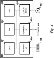
- the devices within the personal computer 305 which enable it to process the images will be described with reference to Figure 4 , whilst the instructions it executes will be described with reference to Figures 5 to 12 .
- the measurement system 301 facilitates determination of the surface roughness by illuminating the surface of the component at a point 306 with coherent light produced by the laser 303. An image of speckle caused by the scattering of the coherent light from the surface is then obtained by the camera 304.
- the image is then converted by the personal computer 305 into a binary image according to a threshold, thereby classifying pixels below the threshold as background pixels and pixels above the threshold as foreground pixels.
- Connected components are then identified in the binary image.
- the connected components are regions of connected foreground pixels, in which any two foreground pixels in a region are joined by a continuous path of foreground pixels.
- the total number of regions identified is then evaluated, along with the number of pixels in the largest region. It has been shown by the present inventors that these values correlate to the actual surface roughness. An indication of the surface roughness of the surface may then be outputted.
- the personal computer 305 comprises a processor such as a central processing unit (CPU) 401.
- central processing unit 401 is a single Intel (RTM) Core i7 processor, having four on-die processing cores operating at 3.2 gigahertz. It is of course possible that other processor configurations could be provided, and indeed several such processors could be present to provide a high degree of parallelism in the execution of instructions.
- RAM 402 random access memory
- DDR double data rate SDRAM totalling 8 gigabytes in capacity.
- RAM 402 allows storage of frequently-used instructions and data structures by the personal computer 305.
- a portion of RAM 402 is reserved as shared memory, which allows high speed inter-process communication between applications running on personal computer 305.
- Permanent storage is provided by a storage device such a solid-state disk (SSD) 403, which in this instance has a capacity of 512 gigabytes.
- SSD 403 stores operating system and application data.
- a hard disk drive could be provided, or several storage devices provided and configured as a RAID array to improve data access times and/or redundancy.
- a network interface 404 allows personal computer 305 to connect to a packet-based network such as the Internet.
- personal computer 305 comprises a peripheral interface 405 such as a universal serial bus (USB (RTM)).
- the peripheral interface 405 connects the personal computer 305 to the camera 304 to allow transfer of the images obtained in use.
- the peripheral interface 405 in the present embodiment is a wired USB (RTM) connection, it is contemplated that other connection types may be used such as wireless connections using, for example, an 802.11 x standard.
- Personal computer 305 also comprises an optical drive, such as a CD-ROM drive 406, into which a non-transitory computer readable medium such as an optical disk, e.g. CD-ROM 407 can be inserted.
- CD-ROM 407 comprises computer-readable instructions to enable the processing method of the present invention. These are, in use, installed on solid-state disk 403, loaded into RAM 402 and then executed by CPU 401. Alternatively, the instructions may be downloaded from a network via the network interface 404 as packet data 408.
- the measurement system 301 comprising the laser 302, the camera 304 and personal computer 305, is powered on.
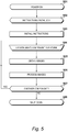
- a question is asked as to whether image processing instructions have been installed on the personal computer 305. If not, then at step 503 the instructions are obtained either from CD-ROM 407 or via the network connection 404 as previously described. Following install, or if the instructions have previously been installed, then at step 504 a manual procedure is carried out consisting of locating a component, such as fan blade 201, in the fixture 302.
- the measurement system 301 then captures images at step 505, and processes them at step 506. Procedures carried out to capture images during step 505 will be described with reference to Figure 6 , whilst procedures carried out to process the images will be described with reference to Figures 8 , 9 and 11 .
- a question is asked at step 507 as to whether another component is to be analysed. If this question is answered in the affirmative, then control returns to step 504 where the new component is located in the fixture 302. If the question asked at step 507 is answered in the negative, then at step 508 the measurement system is shut down.
- a procedure carried out during step 505 to obtain the images of the speckle caused by the scattering of the laser light from the surface of the component are set out in Figure 6 .
- a sample location on the surface of the component being imaged is selected.
- the sample location chosen may be one of few (perhaps even one), or one of a large number.
- the laser 303 and camera 304 may be positioned and angled to illuminate and collect light from the sample location.
- the camera parameters are selected to produce a correct exposure.
- the camera 304 has a fixed aperture lens and so in this step a metering operation takes place in which exposure length and sensor sensitivity are adjusted to give a correct exposure. Such procedures are known.
- an exposure is taken of the speckle pattern caused by the scattering of the laser light by the surface at the sample location.
- the image produced by the camera 304 is then transmitted at step 604 to the personal computer 305, whereupon it may be committed to storage on the solid-state disk 403.
- step 605 a question is asked as to whether any further surface locations are to be sampled. If so, then control returns to step 601 and the above procedures are repeated. If the question asked at step 605 is answered in the negative, then all surface locations have been imaged and step 505 is complete.
- An image 701 is shown in Figure 7A , and is the speckle pattern of a surface location where the roughness was equivalent to 220 grit.
- An image 702 is shown in Figure 7B , and is the speckle pattern of a surface location where the roughness was equivalent to 600 grit.
- An image 703 is shown in Figure 7C , and is the speckle pattern of a surface location where the roughness was equivalent to 1500 grit.
- the present invention therefore utilises an image processing scheme to quantify the differences between the speckle patterns caused by surfaces of different roughness, thereby allowing a determination to be made as to the roughness of the surface.
- Steps carried out in the present embodiment by the personal computer 305 to process the images in step 506 are set out in Figure 8 .
- an image stored on the solid-state disk 403 at step 604 is loaded into memory for processing.
- the image is converted into a binary image, i.e. pixels are classified as either foreground pixels or background pixels depending upon their level in relation to a threshold.
- the threshold is one of a number of possible candidate thresholds. Selection of the candidate threshold to be used for foreground/background classification may performed unsupervised and automatically. This process will be described further with reference to Figure 9 . In alternative implementations, the threshold may be chosen manually, or may be fixed.
- Regions of connected components in the binary image are then identified in step 803, which process will be described with reference to Figure 11 .
- any two foreground pixels in the region must be joined by a continuous path of foreground pixels.
- an indication of a measure of the surface roughness may be output at step 804 by using a lookup table stored in memory to convert the statistics of the output of step 803 into a measure of roughness, for example.
- the statistics are the total number of regions of connected components and the number of pixels in the largest region of connected components.
- a relation may be derived from empirical testing which may be stored as part of the program instructions of the present invention, which is then used during step 804 to convert the statistics generated from the output of step 803 into a measure of surface roughness.
- step 805 Following production of a measure of the roughness for the surface that caused the speckle pattern which was the subject of the image loaded at step 801, a question is asked at step 805 as to whether any other images are to be processed. If so, control returns to step 801 where the next image is loaded for processing. If not, then the question is answered in the negative and step 506 is complete.
- the procedure for conversion into a binary image may be carried out unsupervised and automatically.
- the processes carried out during step 802 to achieve this are set out in Figure 9 .
- the histogram of the image loaded into memory at step 801 is computed.
- the histogram of an image comprises bins, each one of which represents a certain level. Each bin records the number of pixels in the image having that particular level.
- a candidate threshold is selected.
- the images produced by the camera 304 are 8 bit greyscale images
- any number of thresholds could be provided, in any distribution.
- the distribution of thresholds may resemble a gamma curve for example, with lower level thresholds being more spaced apart than higher ones, for example.
- the pixels in the image are classified as either foreground pixels if they are of greater than or equal level to the threshold, or background pixels if they are lower in level than the threshold.
- the histogram produced at step 901 is then utilised to perform step 904.
- the background pixels are considered a class C 0 and the background pixels are another class C 1 .
- the probabilities of class occurrence or weights are ⁇ 0 and ⁇ 1 , which are the zeroth order cumulative moments of the histogram either side of the threshold.
- the class mean levels are ⁇ 0 and ⁇ 1 , which are the first order cumulative moments of the histogram either side of the threshold.
- the optimum threshold is located at a point where there is both the lowest variance in the levels of the background pixels and the lowest variance in the levels of the background pixels, i.e. a minimised within-class variance. It may be shown that maximising the between-class variance is equivalent to minimising the within-class variance, and is more computationally efficient.
- the between-class variance ⁇ B 2 is evaluated by calculating the product of the weights, multiplied by the square of the difference between the background mean and the foreground mean, i.e. ⁇ 0 ⁇ ( ⁇ 0 - ⁇ 1 ) 2 .
- step 905 a question is asked as to whether the value of ⁇ B 2 evaluated at step 904 is the maximum thus far. If so, then the candidate threshold selected at the current iteration of step 902 is set as the new optimum threshold. Then, or if the question asked at step 905 was answered in the negative, then a further question is asked as to whether another candidate threshold needs to be considered. If so, control returns to step 902 where the next candidate threshold is selected. If not, then control proceeds to step 908 where a binary image is outputted utilising the optimum threshold.
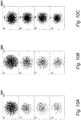
- Binary images derived from the images of the speckle patterns 701, 702 and 703 are shown in Figures 10A, 10B and 10C respectively.
- the binary images were obtained by utilising four different candidate thresholds T 1 to T 4 during step 802.
- binary images 1001, 1002, and 1003, derived from image 701, 702, and 703 respectively using a threshold T1 were deemed to exhibit the maximal between-class variance.
- threshold T 1 was selected as the threshold to use for the output step 908 for each iteration of step 802 as step 506 was applied to images 701, 702 and 703. (It will be appreciated that given different input images more thresholds the result would be likely to be different.)
- Procedures carried out to identify regions of connected components in the binary image during step 803, are set out in Figure 11 .
- the steps will be recognised by those skilled in the art as implementing a flood-fill, whereby for a foreground pixel P, all the other foreground pixels in the region which containing P are labelled identically. It will be appreciated that other algorithms for identifying connected components may be implemented, such as a two-pass or raster scan algorithm.
- an iterative variable L is set to an initial value, which in this example is 1.
- Variable L is used to label pixels as forming part of a particular region of connected components in the image.
- the first unlabelled foreground pixel (P) in the image is selected, and is labelled with L at step 1103.
- a pixel is a neighbouring pixel N if it is 8-connected to the pixel P. In an alternative implementation, a pixel may be considered a neighbouring pixel if it is only 4-connected to the pixel P. If the question asked at step 1104 is answered in the affirmative, then the labels of the neighbouring pixels N are set to L at step 1105. Control returns to step 1104, where the question asked results in unlabelled foreground pixels which neighbour the original neighbouring pixels (if they exist) also being labelled with L at step 1105. This process iterates until the question asked at step 1104 is answered in the negative. At this point, a region of connected components has been identified, and the pixels in the region have all been labelled with L.
- Control therefore proceeds to step 1106, where a question is asked as to whether there is a further unlabelled foreground pixel in the image. If so, then L is incremented at step 1107 and control returns to step 1102 where the next unlabelled foreground pixel is selected, and it, and as a result of the iterative steps 1104 and 1105, the region it forms part of, are labelled with the new value of L.
- step 803 will be complete.
- the total number of regions of connected components and the number of pixels in the largest region of connected components may be counted.
- FIG. 12A A plot of surface roughness - in this case grit number - against the total number of regions of connected components is shown in Figure 12A .
- each pixel simply classifies each pixel as being in one of two states, which greatly reduces the complexity of the algorithm required for identification of connected components.
- greyscale images where each pixel may occupy one of a plurality of levels (e.g. 256 for an 8 bit image), require for example parallel processing techniques to be employed which inherently are greater in terms of complexity.
- steps 802 and 803 Due to the reduction in processing time required by steps 802 and 803 it is envisaged that the present invention may be applied to production-line measurement processes.
Landscapes
- Engineering & Computer Science (AREA)
- Physics & Mathematics (AREA)
- General Physics & Mathematics (AREA)
- Computer Vision & Pattern Recognition (AREA)
- Theoretical Computer Science (AREA)
- Probability & Statistics with Applications (AREA)
- Quality & Reliability (AREA)
- Length Measuring Devices By Optical Means (AREA)
Applications Claiming Priority (1)
| Application Number | Priority Date | Filing Date | Title |
|---|---|---|---|
| GBGB1705406.5A GB201705406D0 (en) | 2017-04-04 | 2017-04-04 | Determining surface roughness |
Publications (2)
| Publication Number | Publication Date |
|---|---|
| EP3385906A1 true EP3385906A1 (de) | 2018-10-10 |
| EP3385906B1 EP3385906B1 (de) | 2020-06-17 |
Family
ID=58682567
Family Applications (1)
| Application Number | Title | Priority Date | Filing Date |
|---|---|---|---|
| EP18162767.0A Active EP3385906B1 (de) | 2017-04-04 | 2018-03-20 | Bestimmung von oberflächenrauigkeit |
Country Status (4)
| Country | Link |
|---|---|
| US (1) | US20180286058A1 (de) |
| EP (1) | EP3385906B1 (de) |
| GB (1) | GB201705406D0 (de) |
| SG (1) | SG10201802487RA (de) |
Cited By (1)
| Publication number | Priority date | Publication date | Assignee | Title |
|---|---|---|---|---|
| WO2024246005A1 (en) * | 2023-06-02 | 2024-12-05 | Trinamix Gmbh | Measurement of surface roughness |
Families Citing this family (5)
| Publication number | Priority date | Publication date | Assignee | Title |
|---|---|---|---|---|
| US11268809B2 (en) * | 2018-11-07 | 2022-03-08 | International Business Machines Corporation | Detecting and correcting deficiencies in surface conditions for bonding applications |
| CN112588878B (zh) * | 2020-11-27 | 2022-09-27 | 北京星航机电装备有限公司 | 一种铝合金薄壁异形件局部校形方法 |
| CN114210741B (zh) * | 2021-11-23 | 2022-08-26 | 北京科技大学 | 一种带钢表面粗糙度在线检测装置及方法 |
| CN114754706A (zh) * | 2022-04-11 | 2022-07-15 | 广东机电职业技术学院 | 机械零件加工表面粗糙度在线检测方法及系统 |
| CN119437098B (zh) * | 2024-11-20 | 2025-11-14 | 中国十七冶集团有限公司 | 一种复杂异性结构清水混凝土构件表面粗糙度检测方法 |
-
2017
- 2017-04-04 GB GBGB1705406.5A patent/GB201705406D0/en not_active Ceased
-
2018
- 2018-03-20 EP EP18162767.0A patent/EP3385906B1/de active Active
- 2018-03-26 SG SG10201802487RA patent/SG10201802487RA/en unknown
- 2018-04-03 US US15/944,272 patent/US20180286058A1/en not_active Abandoned
Non-Patent Citations (3)
| Title |
|---|
| ANONYMOUS: "Otsu's method - Wikipedia", 12 January 2017 (2017-01-12), XP055468978, Retrieved from the Internet <URL:https://en.wikipedia.org/w/index.php?title=Otsu's_method&oldid=759649503> [retrieved on 20180420] * |
| HARIDAS ASWIN ET AL: "Fractal speckle image analysis for surface characterization of aerospace structures", PROCEEDINGS OF SPIE, SPIE, 1000 20TH ST. BELLINGHAM WA 98225-6705 USA, vol. 10449, 13 June 2017 (2017-06-13), pages 104491T - 104491T, XP060093460, ISSN: 0277-786X, ISBN: 978-1-5106-1533-5, DOI: 10.1117/12.2270769 * |
| MAYADA B AL-QUZWENY ET AL: "Different methods for characterizing surface roughness using laser speckle technique", IRAQI JOURNAL OF PHYSICS, vol. 12, 1 January 2014 (2014-01-01), pages 21 - 29, XP055496040 * |
Cited By (1)
| Publication number | Priority date | Publication date | Assignee | Title |
|---|---|---|---|---|
| WO2024246005A1 (en) * | 2023-06-02 | 2024-12-05 | Trinamix Gmbh | Measurement of surface roughness |
Also Published As
| Publication number | Publication date |
|---|---|
| EP3385906B1 (de) | 2020-06-17 |
| SG10201802487RA (en) | 2018-11-29 |
| US20180286058A1 (en) | 2018-10-04 |
| GB201705406D0 (en) | 2017-05-17 |
Similar Documents
| Publication | Publication Date | Title |
|---|---|---|
| EP3385906B1 (de) | Bestimmung von oberflächenrauigkeit | |
| EP3385905A1 (de) | Bestimmung der oberflächenrauheit | |
| Liu et al. | Cloud classification based on structure features of infrared images | |
| CN108665443B (zh) | 一种机械设备故障的红外图像敏感区域提取方法及装置 | |
| EP3649460B1 (de) | Vorrichtung zur optimierung der prüfung der aussenseite eines zielobjekts und verfahren dafür | |
| CN105891230A (zh) | 基于光谱图像分析的水果外表检测方法 | |
| Carr et al. | Road crack detection using a single stage detector based deep neural network | |
| Zhihui et al. | Nondestructive detection of infertile hatching eggs based on spectral and imaging information | |
| JP2005135392A (ja) | 赤目軽減方法 | |
| CN105741244B (zh) | 一种室内巡检机器人弱光下去除阴影和光晕的方法 | |
| CN120254074B (zh) | 基于声发射的风电叶片缺陷检测方法 | |
| US12553816B2 (en) | Method for characterising sperm cells | |
| CN113744154A (zh) | 基于高光谱成像的纤维图像高光检测与消除方法 | |
| RU2605790C2 (ru) | Система и способ оценки влагосодержания потока пара | |
| CN111833336B (zh) | 一种基于高光谱的风电叶片表面砂眼故障的检测系统及方法 | |
| CN117541832B (zh) | 异常检测方法、系统、电子设备及存储介质 | |
| Geraldes et al. | In situ real-time zooplankton detection and classification | |
| CN118918080A (zh) | 基于边缘计算的多特征风机叶片缺陷检测方法及系统 | |
| CN114638785B (zh) | 图像中的强光区域检测方法、系统、介质、设备及终端 | |
| CN116152195A (zh) | 光伏电池板的热斑检测方法、装置及电子设备 | |
| Yani et al. | PV Cell Defects Classification in Electroluminescence Images using Gradient Histogram (HOG) | |
| Yang et al. | A method of steel strip image segmentation based on local gray information | |
| Bouhlal et al. | Multi-Layer Adversarial Detection for Ship Segmentation on NVIDIA Jetson Orin | |
| Garduño-Ramón et al. | Novel Method for Wind Turbines Blades Damage Classification using Image Processing | |
| CN120543552B (zh) | 基于x光的坚果缺陷检测系统及方法 |
Legal Events
| Date | Code | Title | Description |
|---|---|---|---|
| PUAI | Public reference made under article 153(3) epc to a published international application that has entered the european phase |
Free format text: ORIGINAL CODE: 0009012 |
|
| STAA | Information on the status of an ep patent application or granted ep patent |
Free format text: STATUS: THE APPLICATION HAS BEEN PUBLISHED |
|
| AK | Designated contracting states |
Kind code of ref document: A1 Designated state(s): AL AT BE BG CH CY CZ DE DK EE ES FI FR GB GR HR HU IE IS IT LI LT LU LV MC MK MT NL NO PL PT RO RS SE SI SK SM TR |
|
| AX | Request for extension of the european patent |
Extension state: BA ME |
|
| STAA | Information on the status of an ep patent application or granted ep patent |
Free format text: STATUS: REQUEST FOR EXAMINATION WAS MADE |
|
| 17P | Request for examination filed |
Effective date: 20190410 |
|
| RBV | Designated contracting states (corrected) |
Designated state(s): AL AT BE BG CH CY CZ DE DK EE ES FI FR GB GR HR HU IE IS IT LI LT LU LV MC MK MT NL NO PL PT RO RS SE SI SK SM TR |
|
| GRAP | Despatch of communication of intention to grant a patent |
Free format text: ORIGINAL CODE: EPIDOSNIGR1 |
|
| STAA | Information on the status of an ep patent application or granted ep patent |
Free format text: STATUS: GRANT OF PATENT IS INTENDED |
|
| RAP1 | Party data changed (applicant data changed or rights of an application transferred) |
Owner name: ROLLS-ROYCE PLC |
|
| INTG | Intention to grant announced |
Effective date: 20200212 |
|
| GRAS | Grant fee paid |
Free format text: ORIGINAL CODE: EPIDOSNIGR3 |
|
| GRAA | (expected) grant |
Free format text: ORIGINAL CODE: 0009210 |
|
| STAA | Information on the status of an ep patent application or granted ep patent |
Free format text: STATUS: THE PATENT HAS BEEN GRANTED |
|
| AK | Designated contracting states |
Kind code of ref document: B1 Designated state(s): AL AT BE BG CH CY CZ DE DK EE ES FI FR GB GR HR HU IE IS IT LI LT LU LV MC MK MT NL NO PL PT RO RS SE SI SK SM TR |
|
| REG | Reference to a national code |
Ref country code: GB Ref legal event code: FG4D |
|
| REG | Reference to a national code |
Ref country code: CH Ref legal event code: EP |
|
| REG | Reference to a national code |
Ref country code: IE Ref legal event code: FG4D |
|
| REG | Reference to a national code |
Ref country code: DE Ref legal event code: R096 Ref document number: 602018005268 Country of ref document: DE |
|
| REG | Reference to a national code |
Ref country code: AT Ref legal event code: REF Ref document number: 1282261 Country of ref document: AT Kind code of ref document: T Effective date: 20200715 |
|
| PG25 | Lapsed in a contracting state [announced via postgrant information from national office to epo] |
Ref country code: LT Free format text: LAPSE BECAUSE OF FAILURE TO SUBMIT A TRANSLATION OF THE DESCRIPTION OR TO PAY THE FEE WITHIN THE PRESCRIBED TIME-LIMIT Effective date: 20200617 Ref country code: FI Free format text: LAPSE BECAUSE OF FAILURE TO SUBMIT A TRANSLATION OF THE DESCRIPTION OR TO PAY THE FEE WITHIN THE PRESCRIBED TIME-LIMIT Effective date: 20200617 Ref country code: GR Free format text: LAPSE BECAUSE OF FAILURE TO SUBMIT A TRANSLATION OF THE DESCRIPTION OR TO PAY THE FEE WITHIN THE PRESCRIBED TIME-LIMIT Effective date: 20200918 Ref country code: NO Free format text: LAPSE BECAUSE OF FAILURE TO SUBMIT A TRANSLATION OF THE DESCRIPTION OR TO PAY THE FEE WITHIN THE PRESCRIBED TIME-LIMIT Effective date: 20200917 Ref country code: SE Free format text: LAPSE BECAUSE OF FAILURE TO SUBMIT A TRANSLATION OF THE DESCRIPTION OR TO PAY THE FEE WITHIN THE PRESCRIBED TIME-LIMIT Effective date: 20200617 |
|
| REG | Reference to a national code |
Ref country code: LT Ref legal event code: MG4D |
|
| REG | Reference to a national code |
Ref country code: NL Ref legal event code: MP Effective date: 20200617 |
|
| PG25 | Lapsed in a contracting state [announced via postgrant information from national office to epo] |
Ref country code: RS Free format text: LAPSE BECAUSE OF FAILURE TO SUBMIT A TRANSLATION OF THE DESCRIPTION OR TO PAY THE FEE WITHIN THE PRESCRIBED TIME-LIMIT Effective date: 20200617 Ref country code: HR Free format text: LAPSE BECAUSE OF FAILURE TO SUBMIT A TRANSLATION OF THE DESCRIPTION OR TO PAY THE FEE WITHIN THE PRESCRIBED TIME-LIMIT Effective date: 20200617 Ref country code: LV Free format text: LAPSE BECAUSE OF FAILURE TO SUBMIT A TRANSLATION OF THE DESCRIPTION OR TO PAY THE FEE WITHIN THE PRESCRIBED TIME-LIMIT Effective date: 20200617 Ref country code: BG Free format text: LAPSE BECAUSE OF FAILURE TO SUBMIT A TRANSLATION OF THE DESCRIPTION OR TO PAY THE FEE WITHIN THE PRESCRIBED TIME-LIMIT Effective date: 20200917 |
|
| REG | Reference to a national code |
Ref country code: AT Ref legal event code: MK05 Ref document number: 1282261 Country of ref document: AT Kind code of ref document: T Effective date: 20200617 |
|
| PG25 | Lapsed in a contracting state [announced via postgrant information from national office to epo] |
Ref country code: NL Free format text: LAPSE BECAUSE OF FAILURE TO SUBMIT A TRANSLATION OF THE DESCRIPTION OR TO PAY THE FEE WITHIN THE PRESCRIBED TIME-LIMIT Effective date: 20200617 Ref country code: AL Free format text: LAPSE BECAUSE OF FAILURE TO SUBMIT A TRANSLATION OF THE DESCRIPTION OR TO PAY THE FEE WITHIN THE PRESCRIBED TIME-LIMIT Effective date: 20200617 |
|
| PG25 | Lapsed in a contracting state [announced via postgrant information from national office to epo] |
Ref country code: PT Free format text: LAPSE BECAUSE OF FAILURE TO SUBMIT A TRANSLATION OF THE DESCRIPTION OR TO PAY THE FEE WITHIN THE PRESCRIBED TIME-LIMIT Effective date: 20201019 Ref country code: IT Free format text: LAPSE BECAUSE OF FAILURE TO SUBMIT A TRANSLATION OF THE DESCRIPTION OR TO PAY THE FEE WITHIN THE PRESCRIBED TIME-LIMIT Effective date: 20200617 Ref country code: EE Free format text: LAPSE BECAUSE OF FAILURE TO SUBMIT A TRANSLATION OF THE DESCRIPTION OR TO PAY THE FEE WITHIN THE PRESCRIBED TIME-LIMIT Effective date: 20200617 Ref country code: AT Free format text: LAPSE BECAUSE OF FAILURE TO SUBMIT A TRANSLATION OF THE DESCRIPTION OR TO PAY THE FEE WITHIN THE PRESCRIBED TIME-LIMIT Effective date: 20200617 Ref country code: SM Free format text: LAPSE BECAUSE OF FAILURE TO SUBMIT A TRANSLATION OF THE DESCRIPTION OR TO PAY THE FEE WITHIN THE PRESCRIBED TIME-LIMIT Effective date: 20200617 Ref country code: ES Free format text: LAPSE BECAUSE OF FAILURE TO SUBMIT A TRANSLATION OF THE DESCRIPTION OR TO PAY THE FEE WITHIN THE PRESCRIBED TIME-LIMIT Effective date: 20200617 Ref country code: RO Free format text: LAPSE BECAUSE OF FAILURE TO SUBMIT A TRANSLATION OF THE DESCRIPTION OR TO PAY THE FEE WITHIN THE PRESCRIBED TIME-LIMIT Effective date: 20200617 Ref country code: CZ Free format text: LAPSE BECAUSE OF FAILURE TO SUBMIT A TRANSLATION OF THE DESCRIPTION OR TO PAY THE FEE WITHIN THE PRESCRIBED TIME-LIMIT Effective date: 20200617 |
|
| PG25 | Lapsed in a contracting state [announced via postgrant information from national office to epo] |
Ref country code: SK Free format text: LAPSE BECAUSE OF FAILURE TO SUBMIT A TRANSLATION OF THE DESCRIPTION OR TO PAY THE FEE WITHIN THE PRESCRIBED TIME-LIMIT Effective date: 20200617 Ref country code: PL Free format text: LAPSE BECAUSE OF FAILURE TO SUBMIT A TRANSLATION OF THE DESCRIPTION OR TO PAY THE FEE WITHIN THE PRESCRIBED TIME-LIMIT Effective date: 20200617 Ref country code: IS Free format text: LAPSE BECAUSE OF FAILURE TO SUBMIT A TRANSLATION OF THE DESCRIPTION OR TO PAY THE FEE WITHIN THE PRESCRIBED TIME-LIMIT Effective date: 20201017 |
|
| REG | Reference to a national code |
Ref country code: DE Ref legal event code: R097 Ref document number: 602018005268 Country of ref document: DE |
|
| PLBE | No opposition filed within time limit |
Free format text: ORIGINAL CODE: 0009261 |
|
| STAA | Information on the status of an ep patent application or granted ep patent |
Free format text: STATUS: NO OPPOSITION FILED WITHIN TIME LIMIT |
|
| PG25 | Lapsed in a contracting state [announced via postgrant information from national office to epo] |
Ref country code: DK Free format text: LAPSE BECAUSE OF FAILURE TO SUBMIT A TRANSLATION OF THE DESCRIPTION OR TO PAY THE FEE WITHIN THE PRESCRIBED TIME-LIMIT Effective date: 20200617 |
|
| 26N | No opposition filed |
Effective date: 20210318 |
|
| PG25 | Lapsed in a contracting state [announced via postgrant information from national office to epo] |
Ref country code: SI Free format text: LAPSE BECAUSE OF FAILURE TO SUBMIT A TRANSLATION OF THE DESCRIPTION OR TO PAY THE FEE WITHIN THE PRESCRIBED TIME-LIMIT Effective date: 20200617 |
|
| PG25 | Lapsed in a contracting state [announced via postgrant information from national office to epo] |
Ref country code: MC Free format text: LAPSE BECAUSE OF FAILURE TO SUBMIT A TRANSLATION OF THE DESCRIPTION OR TO PAY THE FEE WITHIN THE PRESCRIBED TIME-LIMIT Effective date: 20200617 |
|
| REG | Reference to a national code |
Ref country code: CH Ref legal event code: PL |
|
| REG | Reference to a national code |
Ref country code: BE Ref legal event code: MM Effective date: 20210331 |
|
| PG25 | Lapsed in a contracting state [announced via postgrant information from national office to epo] |
Ref country code: CH Free format text: LAPSE BECAUSE OF NON-PAYMENT OF DUE FEES Effective date: 20210331 Ref country code: IE Free format text: LAPSE BECAUSE OF NON-PAYMENT OF DUE FEES Effective date: 20210320 Ref country code: LU Free format text: LAPSE BECAUSE OF NON-PAYMENT OF DUE FEES Effective date: 20210320 Ref country code: LI Free format text: LAPSE BECAUSE OF NON-PAYMENT OF DUE FEES Effective date: 20210331 |
|
| PG25 | Lapsed in a contracting state [announced via postgrant information from national office to epo] |
Ref country code: BE Free format text: LAPSE BECAUSE OF NON-PAYMENT OF DUE FEES Effective date: 20210331 |
|
| PG25 | Lapsed in a contracting state [announced via postgrant information from national office to epo] |
Ref country code: CY Free format text: LAPSE BECAUSE OF FAILURE TO SUBMIT A TRANSLATION OF THE DESCRIPTION OR TO PAY THE FEE WITHIN THE PRESCRIBED TIME-LIMIT Effective date: 20200617 |
|
| P01 | Opt-out of the competence of the unified patent court (upc) registered |
Effective date: 20230528 |
|
| PG25 | Lapsed in a contracting state [announced via postgrant information from national office to epo] |
Ref country code: HU Free format text: LAPSE BECAUSE OF FAILURE TO SUBMIT A TRANSLATION OF THE DESCRIPTION OR TO PAY THE FEE WITHIN THE PRESCRIBED TIME-LIMIT; INVALID AB INITIO Effective date: 20180320 |
|
| PG25 | Lapsed in a contracting state [announced via postgrant information from national office to epo] |
Ref country code: MK Free format text: LAPSE BECAUSE OF FAILURE TO SUBMIT A TRANSLATION OF THE DESCRIPTION OR TO PAY THE FEE WITHIN THE PRESCRIBED TIME-LIMIT Effective date: 20200617 |
|
| PG25 | Lapsed in a contracting state [announced via postgrant information from national office to epo] |
Ref country code: MT Free format text: LAPSE BECAUSE OF FAILURE TO SUBMIT A TRANSLATION OF THE DESCRIPTION OR TO PAY THE FEE WITHIN THE PRESCRIBED TIME-LIMIT Effective date: 20200617 |
|
| PG25 | Lapsed in a contracting state [announced via postgrant information from national office to epo] |
Ref country code: TR Free format text: LAPSE BECAUSE OF FAILURE TO SUBMIT A TRANSLATION OF THE DESCRIPTION OR TO PAY THE FEE WITHIN THE PRESCRIBED TIME-LIMIT Effective date: 20200617 |
|
| PGFP | Annual fee paid to national office [announced via postgrant information from national office to epo] |
Ref country code: GB Payment date: 20260323 Year of fee payment: 9 |
|
| PGFP | Annual fee paid to national office [announced via postgrant information from national office to epo] |
Ref country code: DE Payment date: 20260320 Year of fee payment: 9 |
|
| PGFP | Annual fee paid to national office [announced via postgrant information from national office to epo] |
Ref country code: FR Payment date: 20260323 Year of fee payment: 9 |