EP3385766A1 - Camera module adopting detachable lens and assembly method thereof - Google Patents
Camera module adopting detachable lens and assembly method thereof Download PDFInfo
- Publication number
- EP3385766A1 EP3385766A1 EP16869969.2A EP16869969A EP3385766A1 EP 3385766 A1 EP3385766 A1 EP 3385766A1 EP 16869969 A EP16869969 A EP 16869969A EP 3385766 A1 EP3385766 A1 EP 3385766A1
- Authority
- EP
- European Patent Office
- Prior art keywords
- lens module
- optical lens
- optical
- module
- lens
- Prior art date
- Legal status (The legal status is an assumption and is not a legal conclusion. Google has not performed a legal analysis and makes no representation as to the accuracy of the status listed.)
- Pending
Links
- 238000000034 method Methods 0.000 title claims description 82
- 230000003287 optical effect Effects 0.000 claims abstract description 964
- 230000008569 process Effects 0.000 claims description 58
- 238000005259 measurement Methods 0.000 claims description 40
- 230000004044 response Effects 0.000 claims description 22
- 238000010438 heat treatment Methods 0.000 claims description 16
- 230000035945 sensitivity Effects 0.000 claims description 8
- 238000012360 testing method Methods 0.000 claims description 7
- 238000012546 transfer Methods 0.000 claims description 4
- 206010027146 Melanoderma Diseases 0.000 claims description 3
- 238000004364 calculation method Methods 0.000 claims description 3
- 238000011160 research Methods 0.000 claims description 3
- 230000000717 retained effect Effects 0.000 claims description 2
- 230000002093 peripheral effect Effects 0.000 claims 2
- 238000004519 manufacturing process Methods 0.000 abstract description 22
- 239000003292 glue Substances 0.000 description 39
- 239000000203 mixture Substances 0.000 description 28
- 230000008901 benefit Effects 0.000 description 16
- 239000000853 adhesive Substances 0.000 description 6
- 230000001070 adhesive effect Effects 0.000 description 6
- 229920001187 thermosetting polymer Polymers 0.000 description 6
- 238000007789 sealing Methods 0.000 description 4
- 238000007711 solidification Methods 0.000 description 4
- 230000008023 solidification Effects 0.000 description 4
- 230000007547 defect Effects 0.000 description 3
- 238000010586 diagram Methods 0.000 description 3
- 238000006073 displacement reaction Methods 0.000 description 3
- 238000012986 modification Methods 0.000 description 3
- 230000004048 modification Effects 0.000 description 3
- 230000008878 coupling Effects 0.000 description 2
- 238000010168 coupling process Methods 0.000 description 2
- 238000005859 coupling reaction Methods 0.000 description 2
- 230000008859 change Effects 0.000 description 1
- 238000012937 correction Methods 0.000 description 1
- 238000011161 development Methods 0.000 description 1
- 238000005516 engineering process Methods 0.000 description 1
- 238000002347 injection Methods 0.000 description 1
- 239000007924 injection Substances 0.000 description 1
- 239000000463 material Substances 0.000 description 1
- 238000010295 mobile communication Methods 0.000 description 1
- 238000012544 monitoring process Methods 0.000 description 1
- 238000003908 quality control method Methods 0.000 description 1
- 230000002441 reversible effect Effects 0.000 description 1
- 239000000523 sample Substances 0.000 description 1
Images





Classifications
-
- G—PHYSICS
- G03—PHOTOGRAPHY; CINEMATOGRAPHY; ANALOGOUS TECHNIQUES USING WAVES OTHER THAN OPTICAL WAVES; ELECTROGRAPHY; HOLOGRAPHY
- G03B—APPARATUS OR ARRANGEMENTS FOR TAKING PHOTOGRAPHS OR FOR PROJECTING OR VIEWING THEM; APPARATUS OR ARRANGEMENTS EMPLOYING ANALOGOUS TECHNIQUES USING WAVES OTHER THAN OPTICAL WAVES; ACCESSORIES THEREFOR
- G03B30/00—Camera modules comprising integrated lens units and imaging units, specially adapted for being embedded in other devices, e.g. mobile phones or vehicles
-
- G—PHYSICS
- G02—OPTICS
- G02B—OPTICAL ELEMENTS, SYSTEMS OR APPARATUS
- G02B7/00—Mountings, adjusting means, or light-tight connections, for optical elements
- G02B7/02—Mountings, adjusting means, or light-tight connections, for optical elements for lenses
- G02B7/021—Mountings, adjusting means, or light-tight connections, for optical elements for lenses for more than one lens
-
- G—PHYSICS
- G02—OPTICS
- G02B—OPTICAL ELEMENTS, SYSTEMS OR APPARATUS
- G02B7/00—Mountings, adjusting means, or light-tight connections, for optical elements
- G02B7/003—Alignment of optical elements
-
- G—PHYSICS
- G02—OPTICS
- G02B—OPTICAL ELEMENTS, SYSTEMS OR APPARATUS
- G02B7/00—Mountings, adjusting means, or light-tight connections, for optical elements
- G02B7/02—Mountings, adjusting means, or light-tight connections, for optical elements for lenses
-
- G—PHYSICS
- G02—OPTICS
- G02B—OPTICAL ELEMENTS, SYSTEMS OR APPARATUS
- G02B7/00—Mountings, adjusting means, or light-tight connections, for optical elements
- G02B7/02—Mountings, adjusting means, or light-tight connections, for optical elements for lenses
- G02B7/023—Mountings, adjusting means, or light-tight connections, for optical elements for lenses permitting adjustment
-
- G—PHYSICS
- G02—OPTICS
- G02B—OPTICAL ELEMENTS, SYSTEMS OR APPARATUS
- G02B7/00—Mountings, adjusting means, or light-tight connections, for optical elements
- G02B7/02—Mountings, adjusting means, or light-tight connections, for optical elements for lenses
- G02B7/025—Mountings, adjusting means, or light-tight connections, for optical elements for lenses using glue
-
- G—PHYSICS
- G03—PHOTOGRAPHY; CINEMATOGRAPHY; ANALOGOUS TECHNIQUES USING WAVES OTHER THAN OPTICAL WAVES; ELECTROGRAPHY; HOLOGRAPHY
- G03B—APPARATUS OR ARRANGEMENTS FOR TAKING PHOTOGRAPHS OR FOR PROJECTING OR VIEWING THEM; APPARATUS OR ARRANGEMENTS EMPLOYING ANALOGOUS TECHNIQUES USING WAVES OTHER THAN OPTICAL WAVES; ACCESSORIES THEREFOR
- G03B17/00—Details of cameras or camera bodies; Accessories therefor
- G03B17/02—Bodies
- G03B17/12—Bodies with means for supporting objectives, supplementary lenses, filters, masks, or turrets
-
- H—ELECTRICITY
- H04—ELECTRIC COMMUNICATION TECHNIQUE
- H04N—PICTORIAL COMMUNICATION, e.g. TELEVISION
- H04N17/00—Diagnosis, testing or measuring for television systems or their details
- H04N17/002—Diagnosis, testing or measuring for television systems or their details for television cameras
-
- H—ELECTRICITY
- H04—ELECTRIC COMMUNICATION TECHNIQUE
- H04N—PICTORIAL COMMUNICATION, e.g. TELEVISION
- H04N23/00—Cameras or camera modules comprising electronic image sensors; Control thereof
- H04N23/50—Constructional details
- H04N23/54—Mounting of pick-up tubes, electronic image sensors, deviation or focusing coils
-
- H—ELECTRICITY
- H04—ELECTRIC COMMUNICATION TECHNIQUE
- H04N—PICTORIAL COMMUNICATION, e.g. TELEVISION
- H04N23/00—Cameras or camera modules comprising electronic image sensors; Control thereof
- H04N23/50—Constructional details
- H04N23/55—Optical parts specially adapted for electronic image sensors; Mounting thereof
-
- H—ELECTRICITY
- H04—ELECTRIC COMMUNICATION TECHNIQUE
- H04N—PICTORIAL COMMUNICATION, e.g. TELEVISION
- H04N23/00—Cameras or camera modules comprising electronic image sensors; Control thereof
- H04N23/57—Mechanical or electrical details of cameras or camera modules specially adapted for being embedded in other devices
Definitions
- the present invention relates to photographic cameras, and more particularly to a camera lens module and a manufacturing method thereof.
- An existing camera module generally comprises a circuit board, a light sensor chip, a lens base, a driver unit, a lens, and other major components being assembled together, wherein the resolution of the camera module can achieve through the image quality control by the circuit board, the light sensor chip, the lens and the driver unit, the tolerance of the structural configuration of the components, and the tolerance of the assembling configuration of the components.
- the camera lens is the most important factor to affect the image resolution.
- the camera module is configured to include one or more lenses in an individual lens assembly.
- the camera lens comprises a lens barrel to support a plurality of lenses therein to provide a dark environment therefor, wherein two or more lens barrels are assembled together to correlatively link the lenses form an integral optical system. Then, the optical system is assembled to the lens base or the driver unit. Through the assembling process, assembly errors may cause the lens eccentrically or tiltedly aligned with the light sensor chip, so as to reduce the resolution of the camera module.
- the tolerance of each lens related to its optical ability and the tolerance of each lens to be mounted in the lens barrel should take into account of the conventional assembling process.
- the invention is advantageous in that it provides a camera lens module with one or more optical lens modules and a manufacturing method thereof, which can eliminate the defects of the conventional camera lens module during the assembling process.
- the assembling process and the calibration process can be integrated into the manufacturing process to ensure the image quality of the camera lens module.
- Another advantage of the invention is to provide a camera lens module with one or more optical lens modules and a manufacturing method thereof, wherein the position adjustment and the calibration are completed before the final assembling of the camera lens to simplify the assembling steps of the camera lens module, to highly increase the production efficiency of the camera lens module, and to reduce the manufacturing cost of the camera lens module.
- Another advantage of the invention is to provide a camera lens module with one or more optical lens modules and a manufacturing method thereof, wherein the calibration of the camera lens module is based on the image quality thereof to adjust the relative position of the lens barrel so as to ensure the higher product yield of the camera lens module.
- Another advantage of the invention is to provide a camera lens module with one or more optical lens modules and a manufacturing method thereof, wherein the camera lens module comprises a plurality of optical lens modules, each comprising at least one optical lens supported in a lens barrel.
- the relative position of each optical lens modules is adjustable to ensure the corrected alignment of the optical lens module so as to ensure the optical quality of the camera lens module.
- Another advantage of the invention is to provide a camera lens module and a manufacturing method thereof, wherein the calibration of the camera lens module with one or more optical lens modules is to adjust the relative positions of the optical lens modules to compensate the unavoidable tolerance of the camera lens module so as to minimize the optical defect of camera lens module and to enhance the production efficiency while being cost effective.
- Another advantage of the invention is to provide a camera lens module with one or more optical lens modules and a manufacturing method thereof, the relative position of the optical lens module is permanently fixed once the calibration thereof is completed to minimize the assembling steps of the camera lens module while being cost effective.
- Another advantage of the invention is to provide a camera lens module with one or more optical lens modules and a manufacturing method thereof, wherein the structural configuration of the camera lens module is compact to reduce the overall size thereof.
- Another advantage of the invention is to provide a camera lens module with one or more optical lens modules and a manufacturing method thereof, wherein the relative position of the optical lens module is adjustable with respect to as many as six axes X, Y, Z, U, V, W thereof.
- Another advantage of the invention is to provide a camera lens module with one or more optical lens modules and a manufacturing method thereof, wherein each optical element to be calibrated can be selectively adjusted at different orientations to speed up the calibration process and to ensure the image quality and precise assembly of the camera lens module.
- Another advantage of the invention is to provide a camera lens module with one or more optical lens modules and a manufacturing method thereof, which can minimize the existing assembling tolerances through the conventional assembling method of the camera lens module so as to reduce the defect of the camera lens module due to the conventional assembling method.
- Another advantage of the invention is to provide a camera lens module with one or more optical lens modules and a manufacturing method thereof, wherein the relative position of at least one of the optical lens module is adjustable to ensure the image quality of the camera lens module.
- Another advantage of the invention is to provide a camera lens module with one or more optical lens modules and a manufacturing method thereof, wherein each optical element to be calibrated is calibrated and adjusted for achieving the acquired image quality of the camera lens module before the relative position of the optical element to be calibrated is fixed.
- Another advantage of the invention is to provide a camera lens module with one or more optical lens modules and a manufacturing method thereof, the calibration process can apply to adjust the relative position of the optical lens, the relative position of the optical lens module, and the relative position of the aperture member. Therefore, the calibration process can be selectively applied any combination of different optical element to be calibrated optical elements to be calibrated to ensure the image quality of the camera lens module.
- a camera lens module comprising:
- the present invention comprises a modularized camera lens module, comprising:
- the present invention comprises a modularized camera lens module, comprising:
- the present invention comprises a modularized camera lens module, comprising:
- the present invention comprises a modularized camera lens module, comprising:
- the present invention comprises a lens assembly, which comprises an optical lens set, a lens barrel set, and an aperture member, wherein the optical lens set comprises at least one optical lens, wherein the lens barrel set comprises at least one lens barrel, wherein the optical lens is supported within the lens barrel along a height direction thereof to form at least one of the optical lens modules.
- the relative position of the optical lens module is adjustable with respect to as many as the six axes X, Y, Z, U, V, W of the camera lens module.
- At least one of the lenses of the optical lens modules is pre-assembled in the respective lens barrel while the assembling position of the pre-assembled lens is arranged to be adjustable with respect to the position of the image sensor.
- the optical lens is arranged movable within the lens barrel to selectively adjust the assembling position of the optical lens within the lens barrel in at least one direction.
- a calibration channel is formed at a barrel wall of the lens barrel communicating an interior thereof with outside and is aligned with respect to the optical lens pre-assembled within the lens barrel, such that the assembling position of the optical lens within the lens barrel can be adjusted through the calibration channel.
- the aperture member is coupled at the top portion of the optical lens module, wherein the relative position of the aperture member with respect to the optical lens module is adjustable.
- the relative position of the aperture member with respect to the optical lens module is adjustable in at least one direction.
- the optical element to be calibrated is pre-assembled by the adhering element.
- the adhering element can be a mixture glue comprising UV glue mixed with thermosetting adhesive, wherein the mixture glue is in a semi-solidified state under the UV exposure and is solidified after heat treatment, such as within an oven. Therefore, once the adhering element is solidified, the relative position of the optical element to be calibrated is permanently fixed in position.
- the image sensor comprises a color filter, a lens base, a photosensitive chip, and a control circuit board, wherein the photosensitive chip is operatively coupled on top of the control circuit board while the color filter and the photosensitive chip are coupled at the lens base.
- the optical lens module is coupled to the lens base that the relative position of the optical lens module with respect to the lens base is adjustable.
- the camera lens module can be a zoom camera lens module to include a driver unit.
- the image sensor comprises a color filter, a photosensitive chip, and a control circuit board, wherein the photosensitive chip is operatively coupled on top of the control circuit board while the color filter and the photosensitive chip are coupled at the lens barrel.
- the driver unit is operatively coupled to the lens barrel.
- the camera lens module is electrified during the pre-assembling process for image acquisition, wherein the calibration measurement such as calibration parameter of the optical lens module is determined through the calibration software to ensure the precise position of the optical lens module.
- the present invention provides a lens assembly which comprises:
- the lens assembly further comprises an aperture member provided on top of the optical lens module at the furthest position, wherein the assembling position of the aperture member is adjustable with respect to the position of the optical lens module.
- At least one of the optical lenses is installed in at least one of the lens barrels in such a manner that the assembling position of the pre-assembled optical lens is arranged to be adjustable inside the respective lens barrel.
- the lens barrel receiving the respective pre-assembled optical lens has at least a calibration channel which is provided in a barrel wall of the lens barrel for communicating an interior thereof with outside, wherein the calibration channel is aligned with respect to the optical lens pre-assembled within the lens barrel, such that the assembling position of the optical lens within the lens barrel can be adjusted through the calibration channel.
- the aperture member, the optical lens and the optical lens module are pre-assembled by an adhering element in a semi-solidified manner.
- the adhering element for pre-assemble can be a mixture glue comprising UV glue mixed with thermosetting adhesive, wherein the mixture glue is in a semi-solidified state under the UV exposure and is solidified after heat treatment. Therefore, once the adhering element is solidified, the whole camera lens module is permanently fixed in position.
- the assembling position of the optical lens within the optical lens module is arranged to be adjusted in at least one direction.
- the assembling position of the aperture member with respect to the top portion of the lens barrel is arranged to be adjusted in at least one direction.
- the relative position of the optical lens module is adjustable with respect to as many as six axes X, Y, Z, U, V, W the of the camera lens module.
- the lens barrel provides at least an optical element to be calibrated therein for supporting at least one optical lens.
- the optical element to be calibrated is formed by a protrusion radially and inwardly extended from an inner barrel wall of the lens barrel.
- the present invention further provides a method of assembling the camera lens module, which comprises the following steps.
- the optical elements to be calibrated include at least one optical lens module which generally comprises at least one optical lens and at least one lens barrel, wherein at least one of the pre-assembled optical lens module is pre-assembled along the photosensitive path of the image sensor, while the assembling position of the pre-assembled optical lens module is arranged to be adjusted with respect to the image sensor.
- the optical elements to be calibrated include at least two optical lens modules which positions are calibrated during assembling process, wherein the optical elements to be calibrated comprises one aperture member which is pre-assembled at the top portion of the optical lens module at the outermost side of the camera lens module and the assembling position of the aperture member is adapted to be adjusted with respect to the relative position of the optical lens module.
- step (A) all the optical elements to be calibrated are pre-assembled by means of adhering element such as UV glue mixed with thermosetting adhesive, wherein the mixture glue is in a semi-solidified state under UV exposure for pre-assembling.
- adhering element such as UV glue mixed with thermosetting adhesive
- the mixture glue is solidified after heat treatment so as to permanently affix the whole camera lens module.
- the camera lens module further comprises a plurality of assembled optical elements which assemble tolerance must be retained within a deviation of acceptable range.
- the pre-assembled camera lens module is electrified to collect images of the camera lens module, wherein the image collection of the camera lens module is based on the capturing of the MTF (Modulation Transfer Function) test target, and the image quality is determined by a MTF value, where the higher MTF value refers to higher image quality.
- MTF Modulation Transfer Function
- a plurality of MTF value will be determined for every image collected from the camera lens module and will be compared with a predetermined threshold. When the MTF value is greater than or equal to the predetermined threshold, the collection and calibration is completed. When the MTF value is lesser than the predetermined threshold, the image collection is repeated for further calibration.
- the camera lens module must be strictly controlled for capturing each image under predetermined environment parameters which includes capturing distance and light source parameters between the MTF test target and the camera lens module to ensure the accuracy and consistency of the image acquisition for ease of the subsequent calibration process.
- the camera lens module should be monitored for eliminating black spot, distortion, and/or shades during the image acquisition process.
- the software used for the calibration of the assembling positions of the optical elements to be calibrated is adapted for the research based on the optical sensitivity of the optical lens components, wherein the software used for computing method of the calibration value of the assembling positions of the optical lens components includes the following steps. (1) Measure the optical characteristics of the camera lens module prior to the calibration, including MTF values, light eccentricity measurement, light axis inclination angle, and curvature of field; and (2) Compute the required calibration value of the assembling positions of the optical element to be calibrated in response to the light eccentricity measurement, light axis inclination angle and the sensitivity of the curvature of field corresponding to the assembling positions of the optical elements to be calibrated.
- the assembling positions of the optical elements to be calibrated with respect to the relative position of the camera lens module is adjusted in at least one direction.
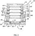
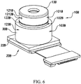
- the camera lens module which is configured as a split-lens module, comprises a lens assembly 10 and an image sensor 20, wherein the lens assembly 10 is located along a light path of the image sensor 20, such that the image sensor 20 can pick up light incident through the lens assembly 10 and can convert the light into image signals. Accordingly, the relative assembling position of the lens assembly 10 with respect to the image sensor 20 is adjustable.
- the image sensor 20 comprises a color filter 21, a lens base 22, a photosensitive chip 23, and a control circuit board 24.
- the color filter 21 is coupled at the lens base 22 at a position above the photosensitive chip 23.
- the color filter 21 is provided along a photosensitive path of the photosensitive chip 23.
- the photosensitive chip 23 is operatively coupled on top of the control circuit board 24, preferably by glue, wherein the control circuit board 24 is supported at a bottom of the lens base 22.
- the lens base 22 which is configured to have a hollow structure, has a first holding groove 221 indently formed within an inner surrounding wall of the lens base 22 at an upper portion thereof, and a second holding groove 222 indently formed within the inner surrounding wall of the lens base 22 at a lower portion thereof to coaxially align with the first holding groove 221.
- the color filter 21 and the photosensitive chip 23 are supported by the first holding groove 221 and the second holding groove 222 respectively, wherein the photosensitive chip 23 is operatively coupled onto the control circuit board 24, such that the photosensitive chip 23 picks up light incident from the lens assembly 10 through the lens base 22 and converts the light into image signals.
- the color filter 21 is disposed at the first holding groove 221, such that the color filter 21 is automatically aligned with the photosensitive path of the photosensitive chip 23.
- the photosensitive chip 23 is further extended to the second holding groove 222 to enlarge the size thereof, such that a larger space is created for the larger photosensitive chip 23 to be installed. As a result, the larger photosensitive chip 23 will provide a larger photosensitive area thereof.
- the first and second holding grooves 221, 222 have a rectangular cross section. It is appreciated that the first and second holding grooves 221, 222 can be modified to have different cross section, such as circular cross section, according to the structural configuration of the image sensor 20.
- first holding groove 221 and/or the second holding groove 222 can be omitted. In other words, there should not be any limitation for the first holding groove 221 and/or second holding groove 222.
- the lens base 22 can be formed by mold injection to have a single integrated body, wherein the first holding groove 221 and the second holding groove 222 are inherently formed or integrally built-in with the lens base 22. Then, the lens base 22 can be mounted on the control circuit board 24. Alternatively, the lens base 22 can be directly mold-injected on the control circuit board 24 to integrally form with the control circuit board 24, wherein the first holding groove 221 is inherently formed or integrally built-in with the lens base 22. Accordingly, the second holding groove 222 will be omitted.
- the shape and the manufacturing method of the control circuit board 24 should not be limited according to the present invention.
- the lens assembly 10 comprises an optical lens set 11, a lens barrel set 12, and an aperture member 13 coupled on top of the lens barrel set 12, wherein the optical lens set 11 is located within the lens barrel set 12 at a position below the aperture member 13 and is located along the photosensitive path of the photosensitive chip 23.
- the lens barrel set 12 is coupled at the image sensor 20, wherein a relative assembling position of the lens barrel set 12 is arranged to be adjusted with respect to the image sensor 20 to ensure the image quality of the camera lens module.
- the camera lens module further comprises a driver unit 30 operatively provided at the lens barrel set 12 and coupled to the lens base 22, wherein the driver unit 30 is arranged to selectively adjust the positional displacement of the lens barrel set 12 along the photosensitive path of the photosensitive chip 23.
- the driver unit 30 comprises a voice coil motor or a piezoelectric motor to drive the lens barrel set 12 to move.
- the optical lens set 11 comprises a first optical lens 111, a second optical lens 112, a third optical lens 113, a fourth optical lens 114, and a fifth optical lens 115, wherein the first to fifth optical lenses 111-115 are arranged for convergence or divergence of the light beam to be collected.
- the lens barrel set 12 comprises a first lens barrel 121, a second lens barrel 122, and a third lens barrel 123.
- the aperture member 13 is coupled at a top edge of the first lens barrel 121 at a position above the first optical lens 111, wherein the first lens barrel 121 comprises a first positioning unit 1211 and a second positioning unit 1212.
- the first and second positioning units 1211, 1212 are radially and inwardly extended from an inner barrel wall of the first lens barrel 121.
- the first and second positioning units 1211, 1212 are provided at a mid-portion and a lower portion of the first lens barrel 121 respectively, wherein the first and second optical lenses 111, 112 are supported by the first and second positioning units 1211, 1212 respectively, such that the first and second optical lenses 111, 112 are spaced apart from each other and are securely mounted within the first lens barrel 121.
- first optical lens 111 and the second optical lens 112 are supported within the first lens barrel 121 to form a first optical lens module 101.
- the first optical lens module 101 is mounted at the outermost position of the camera lens module, i.e. the top position of the lens assembly 10 and the farthest distance from the image sensor 20, wherein the aperture member 13 is coupled at a top portion of the first optical lens module 101.
- the second lens barrel 122 comprises a third positioning unit 1221 radially and inwardly extended from an inner barrel wall of the second lens barrel 122.
- the third positioning unit 1221 is provided at a lower portion of the second lens barrel 122, wherein the third optical lens 113 is supported by the third positioning unit 1221, such that the third optical lens 111 is securely mounted within the first lens barrel 121 to form a second optical lens module 102.
- the third lens barrel 123 comprises a fourth positioning unit 1231 radially and inwardly extended from an inner barrel wall of the third lens barrel 123.
- the fourth positioning unit 1231 is provided at a mid-portion of the third lens barrel 123, wherein the fourth and fifth optical lenses 114, 115 are supported by the fourth positioning unit 1231.
- the fourth optical lens 114 is supported on top of the fourth positioning unit 1231 and the fifth optical lens 115 is supported on below the fourth positioning unit 1231.
- the driver unit 30 is operatively integrated with the third lens barrel 123, such that the fourth and fifth optical lenses 114, 115, the third lens barrel 123, and the driver unit 30 are assembled together to form a third optical lens module 103.
- the first positioning unit 1211, the second positioning unit 1212 and the third positioning unit 1221 are integrally protruded from the inner barrel walls of the first and second lens barrels 121, 122 to form a plurality of annular protruding platforms. It is appreciated that any shape of the protruding platform can be modified as long as the corresponding optical lens can be supported thereby.
- the first optical lens module 101 is coaxially coupled at the second optical lens module 102 by a first adhering element 41.
- the second optical lens module 102 is coaxially coupled at the third optical lens module 103 by a second adhering element 42.
- the third optical lens module 103 is coupled at the lens base 22 by a third adhering element 43.
- Each of the first through third adhering elements 41, 42, 43 is preferably a mixture glue comprising UV glue mixed with thermosetting adhesive, wherein the mixture glue is in a semi-solidified state under UV exposure and is solidified after heat treatment, such as within an oven or in a heated environment.
- the first optical lens module 101, the second optical lens module 102, the third optical lens module 103, and the lens base 22 are coupled with each other by means of the mixture glue in the semi-solidified state to complete the pre-assembling of the camera lens module.
- the first optical lens module 101, the second optical lens module 102 and the third optical lens module 103 are optical elements to be calibrated. Under the initial assembling condition, the first optical lens module 101, the second optical lens module 102, and the third optical lens module 103 can be selectively adjusted to correct an optical specification of the camera lens module for calibration.
- the relative assembling positions of the first optical lens module 101, the second optical lens module 102, the third optical lens module 103 and the lens base 22 are adjustable to fix the assembling tolerance of the lens assembly 10, so as to achieve the acquired image quality of the camera lens module.
- the mix glues are then solidified to securely retain and permanently mount the relative positions of the first optical lens module 101, the second optical lens module 102, the third optical lens module 103 and the lens base 22 for the camera lens module.
- At least one of the optical lenses in one of the first optical lens module 101, the second optical lens module 102, and the third optical lens module 103 is a movable optical lens as a optical correction lens to correct and fix the optical specification of the camera lens module.
- the rest of the optical lenses can be the fixed optical lenses.
- at least one of the optical lenses in one of the first optical lens module 101, the second optical lens module 102, and the third optical lens module 103 serves as an optical element to be calibrated while the rest of the optical lens modules are fixed optical lenses.
- only one lens barrel can be constructed in the lens barrel set 12.
- more than one lens barrels are constructed to form the lens barrel set 12, and more than one optical lenses are mounted on each of the lens barrels.
- the lens barrel with the optical lens or the aperture member can form one or more optical lens modules.
- the numbers of optical lens, lens barrel, and optical lens module can be varied depending on the structural configuration of the camera lens module. Therefore, the present invention should not be limited by the numbers of optical lens, lens barrel, and optical lens module.
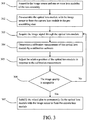
- the present invention further provides a method of assembling the camera lens module with one or more optical lens modules, which comprises the following steps.
- Step 301 Assemble the image sensor and one or more optical lens modules of the camera lens module.
- Step 302 Pre-assemble the optical lens module with the image sensor to form the camera lens module in the pre-assembling state.
- Step 303 Acquire one or more image signals through the optical lens module of the camera lens module.
- Step 304 Determine a calibration measurement including calibration parameter of the optical lens module by a calibration software.
- Step 305 Adjust the assembling position of the optical lens module in response to the calibration measurement.
- Step 306 When the assembling position of the optical lens module is adjusted to achieve a desired resolution of the camera lens module, go to Step 307. Otherwise, repeat Step 303 to Step 305 until the desired resolution of the each of the optical lens modules of the lens assembly, i.e. the image quality is acceptable, is obtained.
- Step 307 Solidify the mixture glue to permanently fix the one or more optical lens modules of the lens assembly with the image sensor to form the camera lens module.
- the Step 301 further comprises the following steps.
- the color filter 21 is coupled at the first holding groove 221 of the lens base 22.
- the photosensitive chip 23 is operatively coupled on the top side of the control circuit board 24.
- the lens base 22 is coupled on the top side of the control circuit board 24 to support the photosensitive chip 23 within the second holding groove 222.
- the assembling process of the image sensor 20 is completed to couple with the lens assembly 10.
- the optical lens set 11, the lens barrel set 12, and the aperture member 13 are assembled to form the first optical lens module 101, the second optical lens module 102, and the third optical lens module 103.
- the aperture member 13 is coupled on the top portion of the first lens barrel 121.
- the first and second optical lenses 111, 112 are supported by the first and second positioning units 1211, 1212 of the first lens barrel 121 respectively to form the first optical lens module 101.
- the aperture member 13, the first optical lens 111, and the second optical lens 112 are affixedly mounted to the first lens barrel 121 in an immovable manner, such that the relative assembling positions of the aperture member 13, the first optical lens 111, and the second optical lens 112 cannot be adjusted to the first lens barrel 121 for the first optical lens module 101.
- the third optical lens 113 is supported by the third positioning unit 1221 of the second lens barrel 122.
- the relative position of the third optical lens 113 cannot be adjusted within the second lens barrel 122, such that the third optical lens 113 is affixed within the second lens barrel 122 by the third positioning unit 1221 thereof in an immovable manner.
- the fourth optical lens 114 is mounted at a top side of the fourth positioning unit 1231 of the third lens barrel 123 while the fifth optical lens 115 is mounted at a bottom side of the fourth positioning unit 1231 of the third lens barrel 123.
- the relative positions of the fourth optical lens 114 and the fifth optical lens 115 cannot be adjusted within the third lens barrel 123, such that the fourth optical lens 114 and the fifth optical lens 115 are affixed within the third lens barrel 123 by the fourth positioning unit 1231 thereof in an immovable manner.
- the driver unit 30 is coaxially mounted to the third lens barrel 123.
- the third adhering element 43 is initially applied to couple the third optical lens module 103 at the lens base 22, the second adhering element 42 is applied to coaxially couple the second optical lens module 102 at the third optical lens module 103, and then the first adhering element 41 is applied to coaxially couple the first optical lens module 101 at the second optical lens module 102. Therefore, the pre-assembly of the optical lens module with the image sensor is completed.
- the adhering steps can be reversed that the first adhering element 41 is applied to initially couple the first optical lens module 101 at the second optical lens module 102, the second adhering element 42 is applied to coaxially couple the second optical lens module 102 at the third optical lens module 103, and then the third adhering element 43 is applied to couple the third optical lens module 103 at the lens base 22, in order to complete the pre-assembly of the optical lens module with the image sensor.
- first, second, third adhering elements 41, 42, 43 are applied in a semi-solidified state during the pre-assembling process.
- each of the first through third adhering elements 41, 42, 43 is a mixture glue comprising UV glue mixed with thermosetting adhesive, wherein the mixture glue is in a semi-solidified state under UV exposure and is solidified after heat treatment. Therefore, the mixture glue in a semi-solidified state for pre-assembling the camera lens module, such that the optical lens modules can be slightly moved and adjusted for calibration while the optical lens modules can be held correspondingly.
- the relative assembling positions of the first optical lens module 101, the second optical lens module 102, and the third optical lens module 103 is able to be selectively adjusted to align with a centerline of the lens assembly 10 so as to align with the centerline of the photosensitive chip 23 within the deviation range thereof for achieving the acquired image quality of the camera lens module.
- the camera lens module at the pre-assembling state is electrified to collect the one or more image signals from the image sensor.
- the calibration measurements such as calibration parameters of the first optical lens module 101, the second optical lens module 102, and the third optical lens module 103 will be determined.
- the image collection of the camera lens module is based on MTF (Modulation Transfer Function) test target
- the image quality is determined by a MTF value.
- MTF Modulation Transfer Function
- a plurality of MTF values will be determined for every image collected from the camera lens module and will be compared with a predetermined threshold. When the MTF value is greater than or equal to the predetermined threshold, the collection and calibration is completed. When the MTF value is lesser than the predetermined threshold, the image collection is repeated for further calibration.
- the camera lens module in each image acquisition process, must be strictly controlled for capturing each image under predetermined environment parameters which includes the capturing distance and light source parameters of the test target and the camera lens module to ensure the accuracy and consistency of the image acquisition for easily calibration.
- the camera lens module should be monitored for eliminating black spot, distortion, and/or shades during the image acquisition process.
- the calibration software is used for calibrating the relative assembling positions of the first optical lens module 101, the second optical lens module 102, and the third optical lens module 103 based on the optical sensitivity of the optical lens. Accordingly, the calibration process of the assembling positions of the first optical lens module 101, the second optical lens module 102, and the third optical lens module 103, based on the calibration software used, comprises the following steps. (1) Measure the optical characteristics of the camera lens module prior to the calibration, including MTF values, light eccentricity measurement, light axis inclination angle, and curvature of field.
- the relative positions of the first optical lens module 101, the second optical lens module 102, and the third optical lens module 103 will be adjusted in response to the calibration measurement as shown in the Step 305.
- the relative positions of the optical lens modules can be adjusted at the same time or individually.
- the relative positions of the first optical lens module 101, the second optical lens module 102, and the third optical lens module 103 can be selectively adjusted to align with the centerline of the lens assembly 10 so as to align with the centerline of the photosensitive chip 23 within the deviation range thereof for achieving the acquired image quality of the camera lens module.
- the relative positions of the first optical lens module 101, the second optical lens module 102, and the third optical lens module 103 are calibrated by the following steps.
- the relative assembling positions of the first optical lens module 101, the second optical lens module 102, and the third optical lens module 103 are defined at six axes X, Y, Z, U, V, W of the camera lens module. Adjust the relative position of each of the first optical lens module 101, the second optical lens module 102, and the third optical lens module 103 along at least one of the horizontal direction, vertical direction, inclination direction, and circumferential direction.
- the image acquisition is required for every position adjustment of the first optical lens module 101, the second optical lens module 102, and the third optical lens module 103, such that each calibration of the camera lens module is based on the previous image acquisition.
- the Step 303, the Step 304, and the Step 305 are repeated to calibrate the relative positions of the first optical lens module 101, the second optical lens module 102, and the third optical lens module 103 until the acquired image quality of the camera lens module is achieved and then the Step 307 is executed to solidify the mixture glue to form the lens assembly 10.
- the mixture glue is exposed under UV environment in the Step 302. Then, after the calibration process is completed, the camera lens module is, for example, sent into the oven for heat treatment of the mixture glue. Once the mixture glue is solidified, the components of the camera lens module are permanently fixed to form the integrated configuration so as to prevent any unwanted displacement of each of the components which will affect the image quality of the camera lens module.
- the first optical lens module 101, the second optical lens module 102, and the third optical lens module 103 are overlapped with each other in a predetermined array.
- the relative positions of the first optical lens module 101, the second optical lens module 102, and the third optical lens module 103 cannot be interchanged.
- the assembling order of the first optical lens module 101, the second optical lens module 102, and the third optical lens module 103 can be altered.
- the first optical lens module 101 can be initially pre-coupled to the second optical lens module 102, and the second optical lens module 102 can be pre-coupled to the third optical lens module 103, then the third optical lens module 103 is pre-coupled to the lens base 22 to form the camera lens module.
- the second optical lens module 102 can be initially pre-coupled to the third optical lens module 103, and the first optical lens module 101 can be pre-coupled to the second optical lens module 102, then the third optical lens module 103 is pre-coupled to the lens base 22 to form the camera lens module.
- the first and second optical lens modules 101, 102 are coupled to the third optical lens module 103, and then the third optical lens module 103 is coupled to the lens base 22 to form the camera lens module.
- the three lens modules are coupled to the lens base 22 to form the camera lens module.
- the present invention should not be limited by the assembling order and numbers of the optical lens modules.
- the relative positions of the optical lens modules, beside the first and the last optical lens modules, can be interchangeable.
- the calibration of the relative positions of the optical lens modules also refers to the calibration of the relative assembling positions of the optical lens modules.
- a camera lens module illustrates an alternative mode of the first embodiment, wherein the camera lens module comprises a lens assembly 10A and an image sensor 20A, wherein the lens assembly 10A is located along a light path of the image sensor 20A, such that the image sensor 20A can pick up light incident through the lens assembly 10A and can convert the light into image signals. Accordingly, the assembling position of the lens assembly 10A with respect to the image sensor 20A is adjustable.
- the lens assembly 10A comprises an optical lens set 11A, a lens barrel set 12A, and an aperture member 13A coupled on top of the lens barrel set 12A, wherein the optical lens set 11A is located within the lens barrel set 12A at a position below the aperture member 13A and is located along the photosensitive path of the photosensitive chip 23A.
- the lens barrel set 12A is coupled at the image sensor 20A, wherein the assembling position of the lens barrel set 12A with respect to the image sensor 20A is adjustable to ensure the image quality of the camera lens module.
- the optical lens set 11A comprises a first optical lens 111A, a second optical lens 112A, and a third optical lens 113A.
- the lens barrel set 12A comprises a first lens barrel 121A, a second lens barrel 122A, and a third lens barrel 123A.
- the first lens barrel 121A, the second lens barrel 122A, and the third lens barrel 123A are orderly and coaxially coupled with each other that the second lens barrel 122A is located between the first lens barrel 121A and the third lens barrel 123A.
- the first optical lens 11 1A, the second optical lens 112A, and the third optical lens 113A are supported within the first lens barrel 121A, the second lens barrel 122A, and the third lens barrel 123A respectively.
- the third lens barrel 123A also serves as a lens base. It is worth mentioning that the driver unit is omitted in the camera lens module of the second embodiment as a fixed-focus camera lens module. According to the present invention, the camera lens module in different embodiments can be the fixed-focus camera lens module or the zoom camera lens module.
- the image sensor 20A comprises a color filter 21A, a lens base 22A (i.e. the third lens barrel 123A), a photosensitive chip 23A, and a control circuit board 24A.
- the color filter 21A is coupled at the third lens barrel 123A at a position above the photosensitive chip 23A.
- the color filter 21A is provided along a photosensitive path of the photosensitive chip 23A.
- the photosensitive chip 23A is operatively coupled on top of the control circuit board 24A.
- the third lens barrel 123A which is configured to have a hollow structure, is mounted on the control circuit board 24A of the image sensor 20A, wherein the third lens barrel 123A has a first holding groove 221A indently formed within an inner surrounding wall of the third lens barrel 123A, a second holding groove 222A indently formed within the inner surrounding wall of the third lens barrel 123A, and a third holding groove 223A indently formed within the inner surrounding wall of the third lens barrel 123A, wherein the first, second, and third holding grooves 221A, 222A, 223A are coaxially aligned with each other and are formed at an upper portion, a mid-portion, and a lower portion of the third lens barrel 123A respectively.
- the color filter 21A is supported by the second holding groove 222A
- the photosensitive chip 23A is supported by the third holding groove 223A and is operatively coupled on the top side of the control circuit board 24A, wherein the photosensitive chip 23A picks up light incident from the lens assembly 10A and converts the light into image signals.
- the aperture member 13A is coupled at a top portion of the first lens barrel 121A, wherein the first lens barrel 121A comprises a first positioning unit 1211A formed at the lower portion of the first lens barrel 121A.
- the first positioning unit 1211A is radially and inwardly extended from an inner barrel wall of the first lens barrel 121A, wherein the first positioning unit 1211A is integrally protruded from the inner barrel walls of the first lens barrel 121A to form an annular protruding platform.
- the first optical lens 111A is supported at the first positioning unit 1211A of the first lens barrel 121A to form a first optical lens module 101A. Accordingly, the first optical lens 11A is located at the farther location of the camera lens module where the aperture member 13A is coupled at the top portion of the first optical lens module 101A.
- the second lens barrel 122A has a second positioning unit 1221A formed at the lower portion of the second lens barrel 122A.
- the second positioning unit 1221A is radially and inwardly extended from an inner barrel wall of the second lens barrel 122A, wherein the second positioning unit 1221A is integrally protruded from the inner barrel walls of the second lens barrel 122A to form an annular protruding platform.
- the second optical lens 112A is supported at the second positioning unit 1221A of the second lens barrel 122A to form a second optical lens module 102A.
- the third lens barrel 123A has a third positioning unit 1231A formed at the upper portion of the third lens barrel 123A.
- the third positioning unit 1231A is radially and inwardly extended from an inner barrel wall of the third lens barrel 123A, wherein the third positioning unit 1231A is integrally protruded from the inner barrel walls of the third lens barrel 123A to form an annular protruding platform.
- the third positioning unit 1231A is located above the first holding groove 221A.
- the third optical lens 113A is supported at the third positioning unit 1231A of the third lens barrel 123A to form a third optical lens module 103A.
- the third optical lens 113A is supported within the third lens barrel 123A, the color filter 21A, the photosensitive chip 23A, and the control circuit board 24A are assembled together with the third optical lens 113A in the third lens barrel 123A.
- the color filter 21A, the photosensitive chip 23A, the control circuit board 24A are assembled in the third lens barrel 123A to form the image senor 20A.
- the first holding groove 221A is configured to have a circular cross section while the second and third holding grooves 222A, 223A are configured to have a rectangular cross section.
- the first positioning unit 1211A, the second positioning unit 1221A, and the third positioning unit 1231A are configured to have a circular protruding platform.
- the shapes of the holding groove and the positioning unit are shown for illustrative purpose and should not be limited.
- the first holding groove 221A, the second holding groove 222A, and the third holding groove 223A can be modified to have different structures for supporting the color filter 21A, the photosensitive chip 23A, and the control circuit board 24A.
- the first positioning unit 1211A, the second positioning unit 1221A, and the third positioning unit 1231A can be modified to have different structures for supporting the first optical lens 111A, the second optical lens 112A, and the third optical lens 113A.
- the optical lens modules are assembled.
- the aperture member 13A and the first optical lens 111A are coupled at the first lens barrel 121A to form the first optical lens module 101A.
- the second optical lens 112A is coupled at the second lens barrel 122A to form the second optical lens module 102A.
- the third optical lens 113A is coupled at the third lens barrel 123A to form the third optical lens module 103A.
- the color filter 21A, the photosensitive chip 23A, and the control circuit board 24A are coupled at the third lens barrel 123A to form the image sensor 20A.
- different tolerances of the camera lens module must be controlled with the acceptable range.
- the first optical lens module 101A and the second optical lens module 102A are pre-assembled, wherein the optical lens module 101A and the second optical lens module 102A are calibrated to selectively adjust the relative positions of the optical lens module 101A and the second optical lens module 102A.
- each of the first optical lens module 101A and the second optical lens module 102A serves as an optical element to be calibrated to selectively adjust the relative positions of the optical lens module 101A and the second optical lens module 102A.
- the second optical lens module 102A is coupled at the third optical lens module 103A via the first adhering element 41A, and then the first optical lens module 101A is coupled at the second optical lens module 102A via the second adhering element 42A.
- the above steps are reversible, wherein the first optical lens module 101A is coupled at the second optical lens module 102A via the second adhering element 42A and then the second optical lens module 102A is coupled at the third optical lens module 103A via the first adhering element 41A.
- the first adhering element 41A and the second adhering element 42A are in a semi-solidified state during the pre-assembling process.
- the calibration of the camera lens module according to the second embodiment is the same as the first embodiment, wherein the relative positions of the first optical lens module 101A and the second optical lens module 102A can be selectively adjusted to align with a centerline of the lens assembly 10A so as to align with the centerline of the photosensitive chip 23A within the deviation range thereof for achieving the acquired image quality of the camera lens module.
- a camera lens module according to a third embodiment illustrates an alternative mode of the first and second embodiments, wherein the camera lens module comprises a lens assembly 10B and an image sensor 20B, wherein the lens assembly 10B is located along a light path of the image sensor 20B, such that the image sensor 20B can pick up light incident through the lens assembly 10B and can convert the light into image signals. Accordingly, the relative assembling position of the lens assembly 10B with respect to the image sensor 20B is adjustable.
- the lens assembly 10B comprises an optical lens set 11B, a lens barrel set 12B, and an aperture member 13B, wherein the optical lens set 11B and the aperture member 13B are coupled at the lens barrel set 12B according to the optical path configuration.
- the optical lens set 11B comprises a first optical lens 111B, a second optical lens 112B, a third optical lens 113B, and a fourth optical lens 114B.
- the lens barrel set 12B comprises a first lens barrel 121B, a second lens barrel 122B, and a third lens barrel 123B.
- the aperture member 13B and the first optical lens 111B are spacedly coupled at the first lens barrel 121B according to the optical path configuration.
- the aperture member 13B is coupled on a top edge of the first lens barrel 121B while the first optical lens 111B is supported within the first lens barrel 121B to form a first optical lens module 101B.
- the second optical lens 112B is supported within the second lens barrel 122B to form a second optical lens module 102B.
- the third optical lens 113B, the fourth optical lens 114B, and the driver unit 30B are coupled at the third lens barrel 123B to form a third optical lens module 103B.
- the image sensor 20B comprises a color filter 21B, a lens base 22B, a photosensitive chip 23B, and a control circuit board 24B.
- the color filter 21B is coupled at the lens base 22B at a position above the photosensitive chip 23B. In other words, the color filter 21B is provided along a photosensitive path of the photosensitive chip 23B.
- the photosensitive chip 23B is operatively coupled on top of the control circuit board 24B.
- the lens base 22B has a first holding groove 221B indently formed within an inner surrounding wall of the lens base 22B and a second holding groove 222B indently formed within the inner surrounding wall of the lens base 22B, wherein the first holding groove 221B and the second holding groove 222B are formed at the upper portion and the lower portion of the lens base 22B respectively.
- the color filter 21B is supported by the first holding groove 221B.
- the photosensitive chip 23B is supported by the second holding groove 222B and is operatively coupled on the top side of the control circuit board 24B, wherein the photosensitive chip 23B picks up light incident from the lens assembly 10B and converts the light into image signals.
- the third lens barrel 123B is permanently affixed to the lens base 22B, such that the relative position of the third lens barrel 123B cannot be adjusted in response to the lens base 22B.
- the third optical lens 113B and the fourth optical lens 114B are supported within the third lens barrel 123B via a third positioning unit 1231B and a fourth positioning unit 1232B respectively.
- the third and fourth positioning units 1231B, 1232B are radially and inwardly extended from an inner barrel wall of the third lens barrel 123B.
- the third optical lens module 103B is permanently affixed to the image sensor 20B, such that the relative position of the third optical lens module 103B cannot be adjusted in response to the image sensor 20B. In other words, the third optical lens module 103B cannot be calibrated during the calibrating process.
- the second optical lens 112B is supported within the second lens barrel 122B via a second positioning unit 1221B which is radially and inwardly extended from an inner barrel wall of the second lens barrel 122B.
- the second optical lens 112B is supported within the second lens barrel 122B to form the second optical lens module 102B for positioning adjustment.
- the first optical lens 111B is supported within the first lens barrel 121B via a first positioning unit 1211B which is radially and inwardly extended from an inner barrel wall of the first lens barrel 121B.
- the first optical lens 111B is supported at the first positioning unit 1211B via the first adhering element 41B in a semi-solidified state, such that the relative position of the first optical lens 111B is adjustable within the first lens barrel 121B.
- the first optical lens 111B is arranged for calibration during the calibrating process.
- the first optical lens 111B serves as one of the optical element to be calibrated optical elements to be calibrated.
- the aperture member 13B is coupled on the top edge of the first lens barrel 121B to form the first optical lens module 101B during the assembling process thereof.
- the first lens barrel 121B has at least one calibration channel 1212B formed at a barrel wall of the first lens barrel 121B to communicate with an interior thereof, wherein the calibration channel 1212B is a through slot.
- the calibration channels 1212B are located corresponding to the location of the first optical lens 111B to enable the relative position of the first optical lens 111B to be calibrated through at least one of the calibration channels 1212B.
- a probe can be slidably inserted into the calibration channel 1212B to contact and move the first optical lens 111B within the first lens barrel 121B, so as to adjust the relative position of the first optical lens 111B within the first lens barrel 121B in a horizontal direction and a vertical direction. Therefore, the calibration of the first optical lens 111B within the first lens barrel 121B can be completed.
- the third optical lens module 103B is affixed to the image sensor 20B. Then, the second optical lens module 102B is coupled at the third optical lens module 103B via the third adhering element 43B, and the first optical lens module 101B is coupled at the second optical lens module 102B via the second adhering element 42B. Accordingly, the second adhering element 42B and the third adhering element 43B are in a semi-solidified state. Therefore, the relative positions of the second optical lens module 102B and the first optical lens module 101B can be individually adjusted for calibration.
- the relative positions of the first optical lens module 101B and the second optical lens module 102B are adjustable. Therefore, the first optical lens module 101B and the second optical lens module 102B are also the optical elements to be calibrated.
- the camera lens module is electrified during the pre-assembling process for image acquisition, wherein the calibration measurement such as calibration parameter of each of the first optical lens module 101B, the second optical lens module 102B, and the first optical lens 111B is determined through the calibration software. Therefore, the relative positions of the first optical lens module 101B, the second optical lens module 102B, and the first optical lens 111B are individually adjusted with respect to the calibration measurements. It is worth mentioning that the image acquisition is required for every position adjustment of the first optical lens module 101B, the second optical lens module 102B, and the first optical lens 111B, such that each calibration of the camera lens module is based on the previous image acquisition.
- the first adhering element 41B, the second adhering element 42B and the third adhering element 43B are solidified to permanently affix the assembling positions of the first optical lens module 101B, the second optical lens module 102B, and the first optical lens 111B.
- the calibration channel 1212B must be sealed.
- a sealing glue can be injected into the calibration channel 1212B to seal the calibration channel 1212B and to secure the relative position of the first optical lens 111B as well.
- the sealing glue can be the above mentioned mixture glue, such that when the sealing glue is injected to seal the calibration channel 1212B, the sealing glue is solidified by the heat treatment at the same time when the first adhering element 41B is solidified to secure the relative position of the first optical lens 111B within the first lens barrel 121B.
- the second adhering element 42B and the third adhering element 43B are also solidified by the heat treatment to secure the relative positions of the first optical lens module 101B and the second optical lens module 102B.
- the calibration process can be completed by serving the first optical lens module 101B as the optical element to be calibrated when the second optical lens module 102B and the third optical lens module 103B are combined as one module to be affixed to the lens base 22B.
- the first optical lens module 101B and the second optical lens module 102B are combined as one module to serve as the optical element to be calibrated, and then the third optical lens module 103B is affixed at the lens base 22B. Therefore, the calibration process can be completed by adjusting the assembling positions of the first optical lens module 101B, the second optical lens module 102B, and the first optical lens 111B.
- first optical lens 111B can be pre-assembled.
- second optical lens 112B can also be pre-assembled, and at least one of the third optical lens 113B and the fourth optical lens 114B can be pre-assembled.
- Each pre-assembled optical lens can be calibrated through the calibration process.
- the present invention further comprises a method of assembling the camera lens module with one or more optical lens modules, which comprises the following steps.
- Step 801 Assemble the image sensor and pre-assemble one or more lens modules of the lens assembly.
- Step 802 Pre-assemble at least one optical lens module with the image sensor to form the camera lens module in the pre-assembling state.
- Step 803 Acquire the image signal through the optical lens module of the lens assembly.
- Step 804 Determine a calibration measurement including calibration parameter of the optical lens module and the optical lens of the lens assembly by means of a calibration software.
- Step 805 Adjust the relative assembling positions of the optical lens module and the optical lens of the lens assembly in response to the calibration measurement.
- Step 806 When the assembling positions of each of the optical lens modules and the optical lens are adjusted to obtain a desired resolution of the camera lens module, go to Step 807. Otherwise, repeat Step 803 to Step 805 until the desired resolution of the camera lens module is obtained.
- Step 807 Solidify the mixture glue to permanently fix the optical lens module and the optical lens with the image sensor to form the camera lens module.
- the relative position of at least one optical lens in the optical lens module is arranged to be adjustable.
- the first lens module 101B is the pre-assembled lens module, wherein the assembling position of the first optical lens 111B can be adjusted in at least one direction.
- the assembling position of the first optical lens 111B can be adjusted along at least one of the horizontal direction, vertical direction, inclination direction, and circumferential direction.
- the assembling position of the second optical lens 112B in the second optical lens module 102B and the assembling positions of the third optical lens 113B and the fourth optical lens 114B in the third optical lens module 103B are fixed and cannot be adjusted.
- the pre-assembling process of the optical lens module with the image sensor is that the third optical lens module 103B is permanently affixed to the lens base 22B. Then, the second optical lens module 102B is coupled to the third optical lens module 103B via the third adhering element 43B. The first optical lens module 101B is then coupled to the second optical lens module 102B via the second adhering element 42B. The second adhering element 42B and the third adhering element 43B are in semi-solidified state under UV exposure during the pre-assembling process, so as to allow the relative positioning adjustments of the first optical lens module 101B and the second optical lens module 102B for calibration.
- the camera lens module in the pre-assembling state is electrified for image acquisition, wherein the calibration measurement such as calibration parameter of each of the first optical lens module 101B, the second optical lens module 102B, and the first optical lens 111B is determined through the calibration software. Therefore, the relative assembling positions of the first optical lens module 101B, the second optical lens module 102B, and the first optical lens 111B are individually adjusted with respect to the calibration measurements.
- the relative positions of the first optical lens module 101B, the second optical lens module 102B, and the first optical lens 111B can be selectively adjusted to align with a centerline of the lens assembly 10B so as to align with the centerline of the photosensitive chip 23B within the deviation range thereof for achieving the acquired image quality of the camera lens module.
- the image acquisition is required for every position adjustment of the first optical lens module 101B, the second optical lens module 102B, and the first optical lens 111B.
- the first adhering element 41B, the second adhering element 42B and the third adhering element 43B are heated and solidified to permanently affix the relative positions of the first optical lens module 101B, the second optical lens module 102B, and the first optical lens 111B.
- the calibration order can be modified that one of the optical lens module and the optical lens can be selected to be calibrated initially and permanently affixed its relative position via the solidification of the mixture glue. Then, the rest of the pre-assembled components can be calibrated and affixed in sequence. In other words, the pre-assembled components are individually calibrated and affixed the relative position via the solidification of the mixture glue in sequence. It is appreciated that the pre-assembled components can be calibrated individually or together and then affixed the relative positions via the solidification of the mixture glue at the same time.
- a camera lens module illustrates an alternative mode of the first through third embodiments, wherein the camera lens module comprises a lens assembly 10C and an image sensor 20C, wherein the lens assembly 10C is located along a light path of the image sensor 20C, such that the image sensor 20C can pick up light incident through the lens assembly 10B and can convert the light into image signals. Accordingly, the relative position of the lens assembly 10C to the image sensor 20C is adjustable for achieving the acquired image quality of the camera lens module.
- the lens assembly 10C comprises an optical lens set 11C, a lens barrel set 12C, and an aperture member 13C.
- the optical lens set 11C comprises a first optical lens 111C, a second optical lens 112C, and a third optical lens 113C.
- the lens barrel set 12C comprises a first lens barrel 121C, a second lens barrel 122C, and a third lens barrel 123C.
- the aperture member 13C is coupled on a top edge of the first lens barrel 121C.
- the first optical lens 111C is supported within the first lens barrel 121C via a first positioning unit 1211C which is radially and inwardly extended from an inner barrel wall of the first lens barrel 121C.
- the first optical lens 111C is mounted in the first lens barrel 121C to form a first optical lens module 101C, wherein the first optical lens module 101C is located at the farther location of the camera lens module where the aperture member 13C is coupled at the top portion of the first optical lens module 101C.
- the assembling position of the aperture member 13C with respect to the first optical lens module 101C is adjustable in at least one direction. In other words, the assembling position of the aperture member 13C can be adjusted along at least one of the horizontal direction, vertical direction, inclination direction, and circumferential direction.
- the second optical lens 112C is supported within the second lens barrel 122C via a second positioning unit 1221C which is radially and inwardly extended from an inner barrel wall of the second lens barrel 122C. Accordingly, the second optical lens 112C is mounted in the second lens barrel 122C to form a second optical lens module 102C.
- the third optical lens 113C is supported within the third lens barrel 123C via a third positioning unit 1231C which is radially and inwardly extended from an inner barrel wall of the third lens barrel 123C. Accordingly, the third optical lens 113C is mounted in the third lens barrel 123C to form a third optical lens module 103C.
- the assembling position of the third optical lens 113C with respect to the third lens barrel 123C is adjustable in at least one direction.
- the assembling position of the third optical lens 113C can be adjusted along at least one of the horizontal direction, vertical direction, inclination direction, and circumferential direction.
- the third optical lens module 103C is affixed at the image sensor 20C in a non-adjustable manner, wherein the third optical lens 113C of the third optical lens module 103C is affixed in position without any positioning adjustment feature.
- the image sensor 20C comprises a color filter 21C, a lens base (i.e. the first lens barrel 123C), a photosensitive chip 23C, and a control circuit board 24C.
- the color filter 21C is coupled at the first lens barrel 123C at a position above the photosensitive chip 23C. In other words, the color filter 21C is provided along a photosensitive path of the photosensitive chip 23C.
- the photosensitive chip 23C is operatively coupled on top of the control circuit board 24C.
- the third lens barrel 123C has a first holding groove 221C indently formed within an inner surrounding wall of the third lens barrel 123C, a second holding groove 222C indently formed within the inner surrounding wall of the third lens barrel 123C, and a third holding groove 223C indently formed within the inner surrounding wall of the third lens barrel 123C.
- the first holding groove 221C, the second holding groove 222C, and the third holding groove 223C are formed at the upper portion, mid-portion, and the lower portion of the third lens barrel 123C respectively.
- the color filter 21C is supported by the second holding groove 222C.
- the photosensitive chip 23C is supported by the third holding groove 223C and is operatively coupled on the top side of the control circuit board 24C.
- the control circuit board 24C is coupled at the bottom side of the third lens barrel 123C, wherein the photosensitive chip 23C picks up light incident from the lens assembly 10C and converts the light into image signals.
- the aperture member 13C is coupled at the first lens barrel 121C via the first adhering element 41C.
- the first optical lens module 101C is coupled at the second optical lens module 102C via the second adhering element 42C.
- the second optical lens module 102C is coupled at the third optical lens module 103C via the third adhering element 43C.
- the third optical lens 113C is supported within the third lens barrel 123C via the fourth adhering element 44C.
- the aperture member 13C, the first optical lens module 101C, the second optical lens module 102C, the third optical lens module 103C, and the third optical lens 113C serve as the optical elements to be calibrated.
- the relative assembling positions/displacements of the aperture member 13C, the first optical lens module 101C, and the second optical lens module 102C are adjustable corresponding to the photosensitive chip 23C.
- the relative positions of the aperture member 13C, the first optical lens module 101C, and the second optical lens module 102C are adjustable during the pre-assembling process.
- the first through fourth adhering elements 41C, 42C, 43C, 44C in a semi-solidified state will also able to initially hold the relative positions of the aperture member 13C, the first optical lens module 101C, and the second optical lens module 102C to prevent any unwanted movement so as to simplify the calibration process.
- the present invention further comprises a method of assembling the camera lens module which comprises the following steps.
- Step 1001 Pre-assemble the optical elements to be calibrated.
- Step 1002 Pre-assemble the optical elements to be calibrated with the image sensor to form the camera lens module in the pre-assembling state.
- Step 1003 Acquire the image signal through the camera lens module.
- Step 1004 Determine a calibration measurement including calibration parameter of the optical elements to be calibrated by a calibration software.
- Step 1005 Adjust the relative positions of the optical elements to be calibrated with the image sensor in response to the calibration measurement.
- Step 1006 When the relative positions of the optical elements to be calibrated are adjusted to obtain a desired resolution of the camera lens module, go to Step 1007. Otherwise, repeat Step 1003 to Step 1005 until the desired resolution of the camera lens module is obtained.
- Step 1007 Solidify the mixture glue to permanently fix the optical elements to be optical elements to be calibrated with the image sensor to form the camera lens module.
- the optical elements to be calibrated include at least one of the optical lens and the aperture member, and at least one of the optical lens modules.
- at least one of the optical lens and the aperture member combines with one optical lens module to serve as the optical elements to be calibrated.
- the relative positions of the optical elements to be calibrated are adjusted to calibrate the camera lens module.
- the third optical lens 113C, the aperture member 13C, the first optical lens module 101C, the second optical lens module 102C are the optical elements to be calibrated.
- the relative positions of the third optical lens 113C, the aperture member 13C, the first optical lens module 101C, the second optical lens module 102C are adjusted to align with a centerline of the lens assembly 10C so as to align with the centerline of the photosensitive chip 23C within the deviation range thereof for achieving the acquired image quality of the camera lens module.
- the assembling tolerance of the optical elements to be calibrated should be controlled for calibration later.
- Step 1003 to Step 1005 the camera lens module is electrified for image acquisition, wherein the calibration measurement such as calibration parameter of the optical elements to be calibrated is determined through the calibration software, such that the optical elements to be calibrated can be calibrated in response to the calibration measurement.
- the calibration process of the optical elements to be calibrated comprises the following steps.
- the camera lens module is electrified for image acquisition, wherein the calibration measurement such as calibration parameter of the third optical lens 113C is determined through the calibration software, such that the third optical lens 113C can be calibrated in response to the calibration measurement.
- the assembling position of the third optical lens 113C is adjusted to align a centerline of the third optical lens 113C with the centerline of the photosensitive chip 23C within the deviation range thereof for achieving the acquired image quality of the camera lens module. If the calibration of the third optical lens 113C cannot achieve the acquired image quality, the calibration process of the third optical lens 113C will repeat until the acquired image quality is achieved.
- the image acquisition is required for every position adjustment of the third optical lens 113C, such that each calibration of the third optical lens 113C is based on the previous image acquisition.
- the fourth adhering element 44C is solidified to permanently affix the assembling position of the third optical lens 113C.
- the camera lens module is electrified for image acquisition, wherein the calibration measurement such as calibration parameter of the second optical lens module 102C is determined through the calibration software, such that the second optical lens module 102C can be calibrated in response to the calibration measurement.
- the assembling position of the second optical lens module 102C is adjusted to align a centerline of the second optical lens module 102C with the centerline of the photosensitive chip 23C within the deviation range thereof for achieving the acquired image quality of the camera lens module. If the calibration of the second optical lens module 102C cannot achieve the acquired image quality, the calibration process of the second optical lens module 102C will repeat until the acquired image quality is achieved.
- the image acquisition is required for every position adjustment of the second optical lens module 102C, such that each calibration of the second optical lens module 102C is based on the previous image acquisition.
- the third adhering element 43C is solidified to permanently affix the assembling position of the second optical lens module 102C.
- the camera lens module is electrified for image acquisition, wherein the calibration measurement such as calibration parameter of the first optical lens module 101C is determined through the calibration software, such that the first optical lens module 101C can be calibrated in response to the calibration measurement.
- the assembling position of the first optical lens module 101C is adjusted to align a centerline of the first optical lens module 101C with the centerline of the photosensitive chip 23C within the deviation range thereof for achieving the acquired image quality of the camera lens module. If the calibration of the first optical lens module 101C cannot achieve the acquired image quality, the calibration process of the first optical lens module 101C will repeat until the acquired image quality is achieved.
- the image acquisition is required for every position adjustment of the first optical lens module 101C, such that each calibration of the first optical lens module 101C is based on the previous image acquisition.
- the second adhering element 42C is solidified to permanently affix the assembling position of the first optical lens module 101C.
- the camera lens module is electrified for image acquisition, wherein the calibration measurement such as calibration parameter of the aperture member 13C is determined through the calibration software, such that the aperture member 13C can be calibrated in response to the calibration measurement.
- the assembling position of the aperture member 13C is adjusted to align a centerline of the aperture member 13C with the centerline of the photosensitive chip 23C within the deviation range thereof for achieving the acquired image quality of the camera lens module. If the calibration of the aperture member 13C cannot achieve the acquired image quality, the calibration process of the aperture member 13C will repeat until the acquired image quality is achieved.
- the image acquisition is required for every position adjustment of the aperture member 13C, such that each calibration of the aperture member 13C is based on the previous image acquisition.
- the first adhering element 41C is solidified to permanently affix the assembling position of the aperture member 13C.
- the relative assembling positions of the third optical lens 113C, the aperture member 13C, the first optical lens module 101C, the second optical lens module 102C are permanently fixed to form the camera lens module.
- Each of the first adhering element 41C, the second adhering element 42C, the third adhering element 43C, and the fourth adhering element 44C is preferably a mixture glue comprising UV glue mixed with thermosetting adhesive, wherein the mixture glue is in a semi-solidified state under the UV exposure and is solidified after heat treatment, such as within an oven. Therefore, before the solidification of the mixture glue, the assembling positions of the optical elements to be calibrated can be adjusted.
- the calibration software is used for calibrating the relative positions of the third optical lens 113C, the aperture member 13C, the first optical lens module 101C, the second optical lens module 102C based on the sensitivity of the optical lens. Accordingly, the calibration process of the third optical lens 113C, the aperture member 13C, the first optical lens module 101C, the second optical lens module 102C comprises the following steps. Measure the optical characteristics of the camera lens module prior to the calibration, including light eccentricity measurement, light axis inclination angle, and curvature of field.
- the calibration measurements such as calibration parameters of the third optical lens 113C, the aperture member 13C, the first optical lens module 101C, the second optical lens module 102C.
Landscapes
- Physics & Mathematics (AREA)
- General Physics & Mathematics (AREA)
- Optics & Photonics (AREA)
- Engineering & Computer Science (AREA)
- Signal Processing (AREA)
- Multimedia (AREA)
- Biomedical Technology (AREA)
- General Health & Medical Sciences (AREA)
- Health & Medical Sciences (AREA)
- Lens Barrels (AREA)
- Studio Devices (AREA)
- Manufacturing & Machinery (AREA)
- Microelectronics & Electronic Packaging (AREA)
- Focusing (AREA)
- Prostheses (AREA)
- Optical Couplings Of Light Guides (AREA)
Abstract
Description
- This is a non-provisional application that claims priority to international application number
PCT/CN2016/107886 - A portion of the disclosure of this patent document contains material which is subject to copyright protection. The copyright owner has no objection to any reproduction by anyone of the patent disclosure, as it appears in the United States Patent and Trademark Office patent files or records, but otherwise reserves all copyright rights whatsoever.
- The present invention relates to photographic cameras, and more particularly to a camera lens module and a manufacturing method thereof.
- With the rapid development of mobile communication technologies, camera modules have become a standardized equipment for electronic apparatus such as smartphones, portable computers, tablet computers, televisions, vehicle monitoring systems, and surveillance systems. Accordingly, the camera module has been rapidly developed toward major concerns of how to improve the production yield and efficiency, how to reduce the cost, and how to improve the image capturing quality. An existing camera module generally comprises a circuit board, a light sensor chip, a lens base, a driver unit, a lens, and other major components being assembled together, wherein the resolution of the camera module can achieve through the image quality control by the circuit board, the light sensor chip, the lens and the driver unit, the tolerance of the structural configuration of the components, and the tolerance of the assembling configuration of the components.
- Within all major components of the camera module, the camera lens is the most important factor to affect the image resolution. Under normal circumstances, the camera module is configured to include one or more lenses in an individual lens assembly. In particular, the camera lens comprises a lens barrel to support a plurality of lenses therein to provide a dark environment therefor, wherein two or more lens barrels are assembled together to correlatively link the lenses form an integral optical system. Then, the optical system is assembled to the lens base or the driver unit. Through the assembling process, assembly errors may cause the lens eccentrically or tiltedly aligned with the light sensor chip, so as to reduce the resolution of the camera module. Furthermore, the tolerance of each lens related to its optical ability and the tolerance of each lens to be mounted in the lens barrel should take into account of the conventional assembling process. Even though the quality of each lens can be guaranteed and each lens can be precisely installed into the lens barrel, the tolerance of assembling the lens barrels together will also take into account of the conventional assembling process. It is because the assembling tolerance of the lens assembly cannot be corrected once the lens barrels are assembled. In other words, these tolerances will reduce the optical quality of the lens assembly and affect the productivity and image quality of the lens assembly. Therefore, there is a demand for improving the existing assembling process of the lens assembly to ensure the image quality thereof.
- The invention is advantageous in that it provides a camera lens module with one or more optical lens modules and a manufacturing method thereof, which can eliminate the defects of the conventional camera lens module during the assembling process. The assembling process and the calibration process can be integrated into the manufacturing process to ensure the image quality of the camera lens module.
- Another advantage of the invention is to provide a camera lens module with one or more optical lens modules and a manufacturing method thereof, wherein the position adjustment and the calibration are completed before the final assembling of the camera lens to simplify the assembling steps of the camera lens module, to highly increase the production efficiency of the camera lens module, and to reduce the manufacturing cost of the camera lens module.
- Another advantage of the invention is to provide a camera lens module with one or more optical lens modules and a manufacturing method thereof, wherein the calibration of the camera lens module is based on the image quality thereof to adjust the relative position of the lens barrel so as to ensure the higher product yield of the camera lens module.
- Another advantage of the invention is to provide a camera lens module with one or more optical lens modules and a manufacturing method thereof, wherein the camera lens module comprises a plurality of optical lens modules, each comprising at least one optical lens supported in a lens barrel. The relative position of each optical lens modules is adjustable to ensure the corrected alignment of the optical lens module so as to ensure the optical quality of the camera lens module.
- Another advantage of the invention is to provide a camera lens module and a manufacturing method thereof, wherein the calibration of the camera lens module with one or more optical lens modules is to adjust the relative positions of the optical lens modules to compensate the unavoidable tolerance of the camera lens module so as to minimize the optical defect of camera lens module and to enhance the production efficiency while being cost effective.
- Another advantage of the invention is to provide a camera lens module with one or more optical lens modules and a manufacturing method thereof, the relative position of the optical lens module is permanently fixed once the calibration thereof is completed to minimize the assembling steps of the camera lens module while being cost effective.
- Another advantage of the invention is to provide a camera lens module with one or more optical lens modules and a manufacturing method thereof, wherein the structural configuration of the camera lens module is compact to reduce the overall size thereof.
- Another advantage of the invention is to provide a camera lens module with one or more optical lens modules and a manufacturing method thereof, wherein the relative position of the optical lens module is adjustable with respect to as many as six axes X, Y, Z, U, V, W thereof.
- Another advantage of the invention is to provide a camera lens module with one or more optical lens modules and a manufacturing method thereof, wherein each optical element to be calibrated can be selectively adjusted at different orientations to speed up the calibration process and to ensure the image quality and precise assembly of the camera lens module.
- Another advantage of the invention is to provide a camera lens module with one or more optical lens modules and a manufacturing method thereof, which can minimize the existing assembling tolerances through the conventional assembling method of the camera lens module so as to reduce the defect of the camera lens module due to the conventional assembling method.
- Another advantage of the invention is to provide a camera lens module with one or more optical lens modules and a manufacturing method thereof, wherein the relative position of at least one of the optical lens module is adjustable to ensure the image quality of the camera lens module.
- Another advantage of the invention is to provide a camera lens module with one or more optical lens modules and a manufacturing method thereof, wherein each optical element to be calibrated is calibrated and adjusted for achieving the acquired image quality of the camera lens module before the relative position of the optical element to be calibrated is fixed.
- Another advantage of the invention is to provide a camera lens module with one or more optical lens modules and a manufacturing method thereof, the calibration process can apply to adjust the relative position of the optical lens, the relative position of the optical lens module, and the relative position of the aperture member. Therefore, the calibration process can be selectively applied any combination of different optical element to be calibrated optical elements to be calibrated to ensure the image quality of the camera lens module.
- Additional advantages and features of the invention will become apparent from the description which follows, and may be realized by means of the instrumentalities and combinations particular point out in the appended claims.
- According to the present invention, the foregoing and other objects and advantages are attained by a camera lens module, comprising:
- an image sensor; and
- a lens assembly which comprises a first optical lens module, a second optical lens module, and a third optical lens module;
- wherein the first optical lens module comprises a first optical lens, a second optical lens, and a first lens barrel, wherein the first optical lens and the second optical lenses are spacedly supported within the first lens barrel, wherein the second optical lens module comprises a third optical lens and a second lens barrel, wherein the third optical lens is supported within the second lens barrel, wherein the third optical lens module comprise a fourth optical lens, a fifth optical lens, and a third lens barrel, wherein the fourth optical lens and the fifth optical lenses are spacedly supported within the third lens barrel;
- wherein the first optical lens module, the second optical lens module, and the third optical lens module are orderly pre-assembled on the image sensor in response to a height direction of the camera lens module in a position adjusting manner, wherein the assembling position of each of the first optical lens module, the second optical lens module, and the third optical lens module is adjustable with respect to the position of the image sensor for calibration, such that the first optical lens module, the second optical lens module, and the third optical lens module are adjusted to align with a photosensitive path of the image sensor so as to enhance the image quality of the camera lens module.
- In accordance with another aspect of the invention, the present invention comprises a modularized camera lens module, comprising:
- an image sensor; and
- a lens assembly which comprises a first optical lens module, a second optical lens module, and a third optical lens module;
- wherein the first optical lens module comprises a first optical lens and a first lens barrel, wherein the first optical lens is supported within the first lens barrel, wherein the second optical lens module comprises a second optical lens and a second lens barrel, wherein the second optical lens is supported within the second lens barrel, wherein the third optical lens module comprises a third optical lens and a third lens barrel, wherein the third optical lens is supported within the third lens barrel;
- wherein the third optical lens module is affixed on the image sensor in a non-adjustable manner, wherein the first optical lens module and the second optical lens module are orderly pre-assembled on the third optical lens module in response to a height direction of the camera lens module in a position adjusting manner, wherein the assembling position of each of the first optical lens module and the second optical lens module is adjustable with respect to the position of the image sensor for calibration, such that the first optical lens module, the second optical lens module and the third optical lens module are adjusted to align with a photosensitive path of the image sensor, so as to enhance the image quality of the camera lens module.
- In accordance with another aspect of the invention, the present invention comprises a modularized camera lens module, comprising:
- an image sensor; and
- a lens assembly which comprises a first optical lens module, a second optical lens module, and a third optical lens module;
- wherein the first optical lens module comprises a first optical lens and a first lens barrel, wherein the first optical lens is supported within the first lens barrel, wherein the second optical lens module comprises a second optical lens and a second lens barrel, wherein the second optical lens is supported within the second lens barrel, wherein the third optical lens module comprises a third optical lens, a fourth optical lens, and a third lens barrel, wherein the third optical lens and the fourth optical lens are spacedly supported within the third lens barrel;
- wherein the first optical lens module and the second optical lens module are orderly pre-assembled on the third optical lens module in response to a height direction of the camera lens module in a position adjusting manner, wherein the assembling position of each of the first optical lens module and the second optical lens module is adjustable with respect to the position of the image sensor for calibration, such that the first optical lens module, the second optical lens module and the third optical lens module are adjusted to align with a photosensitive path of the image sensor, so as to enhance the image quality of the camera lens module;
- wherein the first lens barrel has at least a calibration channel communicating with an interior of the first lens barrel with outside, wherein the calibration channel is alignedly extended to the first optical lens, such that the assembling position of the first optical lens within the first lens barrel is adjustable through the calibration channel.
- In accordance with another aspect of the invention, the present invention comprises a modularized camera lens module, comprising:
- an image sensor; and
- a lens assembly which comprises a first optical lens module, a second optical lens module, and a third optical lens module;
- wherein the first optical lens module comprises a first optical lens and a first lens barrel, wherein the first optical lens is supported within the first lens barrel, wherein the second optical lens module comprises a second optical lens and a second lens barrel, wherein the second optical lens is supported within the second lens barrel, wherein the third optical lens module comprises a third optical lens and a third lens barrel, wherein the third optical lens is supported within the third lens barrel;
- wherein the third optical lens module is affixed on the image sensor in a non-adjustable manner, wherein the first optical lens module and the second optical lens module are orderly pre-assembled on the third optical lens module in response to a height direction of the camera lens module in a position adjusting manner, wherein the assembling position of each of the first optical lens module and the second optical lens module is adjustable with respect to the position of the image sensor for calibration, such that the first optical lens module, the second optical lens module and the third optical lens module are adjusted to align with a photosensitive path of the image sensor, so as to enhance the image quality of the camera lens module;
- wherein the third lens barrel has at least a calibration channel communicating with an interior of the third lens barrel with outside, wherein the calibration channel is alignedly extended to the third optical lens, such that the assembling position of the third optical lens within the third lens barrel is adjustable through the calibration channel.
- In accordance with another aspect of the invention, the present invention comprises a modularized camera lens module, comprising:
- an image sensor; and
- a lens assembly which comprises at least two optical lens modules pre-assembled at a position to align with a photosensitive path of the image sensor, wherein an assembling position of at least one of the optical lens modules is adjustable to align with the photosensitive path of the image sensor.
- In accordance with another aspect of the invention, the present invention comprises a lens assembly, which comprises an optical lens set, a lens barrel set, and an aperture member, wherein the optical lens set comprises at least one optical lens, wherein the lens barrel set comprises at least one lens barrel, wherein the optical lens is supported within the lens barrel along a height direction thereof to form at least one of the optical lens modules.
- In one embodiment, the relative position of the optical lens module is adjustable with respect to as many as the six axes X, Y, Z, U, V, W of the camera lens module.
- In one embodiment, at least one of the lenses of the optical lens modules is pre-assembled in the respective lens barrel while the assembling position of the pre-assembled lens is arranged to be adjustable with respect to the position of the image sensor.
- In particular, the optical lens is arranged movable within the lens barrel to selectively adjust the assembling position of the optical lens within the lens barrel in at least one direction.
- In one embodiment, a calibration channel is formed at a barrel wall of the lens barrel communicating an interior thereof with outside and is aligned with respect to the optical lens pre-assembled within the lens barrel, such that the assembling position of the optical lens within the lens barrel can be adjusted through the calibration channel.
- In one embodiment, the aperture member is coupled at the top portion of the optical lens module, wherein the relative position of the aperture member with respect to the optical lens module is adjustable.
- In one embodiment, the relative position of the aperture member with respect to the optical lens module is adjustable in at least one direction.
- In one embodiment, the optical element to be calibrated is pre-assembled by the adhering element.
- In one embodiment, the adhering element can be a mixture glue comprising UV glue mixed with thermosetting adhesive, wherein the mixture glue is in a semi-solidified state under the UV exposure and is solidified after heat treatment, such as within an oven. Therefore, once the adhering element is solidified, the relative position of the optical element to be calibrated is permanently fixed in position.
- In one embodiment, the image sensor comprises a color filter, a lens base, a photosensitive chip, and a control circuit board, wherein the photosensitive chip is operatively coupled on top of the control circuit board while the color filter and the photosensitive chip are coupled at the lens base. The optical lens module is coupled to the lens base that the relative position of the optical lens module with respect to the lens base is adjustable.
- In one embodiment, the camera lens module can be a zoom camera lens module to include a driver unit. The image sensor comprises a color filter, a photosensitive chip, and a control circuit board, wherein the photosensitive chip is operatively coupled on top of the control circuit board while the color filter and the photosensitive chip are coupled at the lens barrel. The driver unit is operatively coupled to the lens barrel.
- In one embodiment, the camera lens module is electrified during the pre-assembling process for image acquisition, wherein the calibration measurement such as calibration parameter of the optical lens module is determined through the calibration software to ensure the precise position of the optical lens module.
- In accordance with another aspect of the invention, the present invention provides a lens assembly which comprises:
- an optical lens set comprising at least two optical lenses; and
- a lens barrel set comprising at least two lens barrels, wherein at least one of the two optical lenses is correspondingly installed within one of the optical barrels, wherein when all the optical lenses are installed in the lens barrels respectively, at least two optical lens modules are formed, wherein the adjacent optical lens modules are pre-assembled while the assembling position between the optical lens modules is adjustable.
- In one embodiment, the lens assembly further comprises an aperture member provided on top of the optical lens module at the furthest position, wherein the assembling position of the aperture member is adjustable with respect to the position of the optical lens module.
- In one embodiment, at least one of the optical lenses is installed in at least one of the lens barrels in such a manner that the assembling position of the pre-assembled optical lens is arranged to be adjustable inside the respective lens barrel.
- In one embodiment, the lens barrel receiving the respective pre-assembled optical lens has at least a calibration channel which is provided in a barrel wall of the lens barrel for communicating an interior thereof with outside, wherein the calibration channel is aligned with respect to the optical lens pre-assembled within the lens barrel, such that the assembling position of the optical lens within the lens barrel can be adjusted through the calibration channel.
- In one embodiment, the aperture member, the optical lens and the optical lens module are pre-assembled by an adhering element in a semi-solidified manner.
- In one embodiment, the adhering element for pre-assemble can be a mixture glue comprising UV glue mixed with thermosetting adhesive, wherein the mixture glue is in a semi-solidified state under the UV exposure and is solidified after heat treatment. Therefore, once the adhering element is solidified, the whole camera lens module is permanently fixed in position.
- In one embodiment, the assembling position of the optical lens within the optical lens module is arranged to be adjusted in at least one direction.
- In one embodiment, the assembling position of the aperture member with respect to the top portion of the lens barrel is arranged to be adjusted in at least one direction.
- In one embodiment, when the lens assembly is installed within the camera lens module, the relative position of the optical lens module is adjustable with respect to as many as six axes X, Y, Z, U, V, W the of the camera lens module.
- In one embodiment, the lens barrel provides at least an optical element to be calibrated therein for supporting at least one optical lens.
- In one embodiment, the optical element to be calibrated is formed by a protrusion radially and inwardly extended from an inner barrel wall of the lens barrel.
- Accordingly, the present invention further provides a method of assembling the camera lens module, which comprises the following steps.
- (A) Pre-assemble optical elements to be calibrated to form the camera lens module in the pre-assembling state.
- (B) Acquire the image signal through the optical lens module of the lens assembly.
- (C) Determine a calibration measurement including calibration parameter of the optical lens module of the lens assembly by a calibration software.
- (D) Adjust the relative assembling positions of the optical lens module of the lens assembly in response to the calibration measurement.
- (E) When the result of the calibration meets an acquired resolution, such as relative assembling position of the optical lens module of the lens assembly is adjusted to obtain the acquired resolution of the camera lens module, executing the step (F), or repeat the steps (B)-(D) when the result of the calibration fails to meet the desired resolution.
- (F) Permanently fix the camera lens module, such as solidifying the mixture glue to permanently fix the optical lens module of the lens assembly with the image sensor to form the camera lens module.
- In one embodiment, in the step (A), the optical elements to be calibrated include at least one optical lens module which generally comprises at least one optical lens and at least one lens barrel, wherein at least one of the pre-assembled optical lens module is pre-assembled along the photosensitive path of the image sensor, while the assembling position of the pre-assembled optical lens module is arranged to be adjusted with respect to the image sensor.
- In one embodiment, in the step (A), the optical elements to be calibrated include at least two optical lens modules which positions are calibrated during assembling process, wherein the optical elements to be calibrated comprises one aperture member which is pre-assembled at the top portion of the optical lens module at the outermost side of the camera lens module and the assembling position of the aperture member is adapted to be adjusted with respect to the relative position of the optical lens module.
- In one embodiment, in the step (A), all the optical elements to be calibrated are pre-assembled by means of adhering element such as UV glue mixed with thermosetting adhesive, wherein the mixture glue is in a semi-solidified state under UV exposure for pre-assembling. After calibration of the optical elements to be calibrated, in the step (F), the mixture glue is solidified after heat treatment so as to permanently affix the whole camera lens module.
- In one embodiment, in the step (A), the camera lens module further comprises a plurality of assembled optical elements which assemble tolerance must be retained within a deviation of acceptable range.
- In one embodiment, in the step (B), the pre-assembled camera lens module is electrified to collect images of the camera lens module, wherein the image collection of the camera lens module is based on the capturing of the MTF (Modulation Transfer Function) test target, and the image quality is determined by a MTF value, where the higher MTF value refers to higher image quality. A plurality of MTF value will be determined for every image collected from the camera lens module and will be compared with a predetermined threshold. When the MTF value is greater than or equal to the predetermined threshold, the collection and calibration is completed. When the MTF value is lesser than the predetermined threshold, the image collection is repeated for further calibration.
- During each image acquisition process, the camera lens module must be strictly controlled for capturing each image under predetermined environment parameters which includes capturing distance and light source parameters between the MTF test target and the camera lens module to ensure the accuracy and consistency of the image acquisition for ease of the subsequent calibration process.
- During the collecting process of collecting images, to the MTF values, the camera lens module should be monitored for eliminating black spot, distortion, and/or shades during the image acquisition process.
- In one embodiment, in the step (C), the software used for the calibration of the assembling positions of the optical elements to be calibrated is adapted for the research based on the optical sensitivity of the optical lens components, wherein the software used for computing method of the calibration value of the assembling positions of the optical lens components includes the following steps. (1) Measure the optical characteristics of the camera lens module prior to the calibration, including MTF values, light eccentricity measurement, light axis inclination angle, and curvature of field; and (2) Compute the required calibration value of the assembling positions of the optical element to be calibrated in response to the light eccentricity measurement, light axis inclination angle and the sensitivity of the curvature of field corresponding to the assembling positions of the optical elements to be calibrated.
- In one embodiment, in the step (D), the assembling positions of the optical elements to be calibrated with respect to the relative position of the camera lens module is adjusted in at least one direction.
- Still further objects and advantages will become apparent from a consideration of the ensuing description and drawings.
- These and other objectives, features, and advantages of the present invention will become apparent from the following detailed description, the accompanying drawings, and the appended claims.
-
-
Fig. 1 is a perspective view of a camera lens module with one or more optical lens modules according to a first preferred embodiment of the present invention. -
Fig. 2 is a sectional view of the camera lens module with one or more optical lens modules according to the above first preferred embodiment of the present invention. -
Fig. 3 is a flow diagram illustrating the assembling method of the camera lens module with one or more optical lens modules according to the above first preferred embodiment of the present invention. -
Fig. 4 is a perspective view of a camera lens module with one or more optical lens modules according to a second preferred embodiment of the present invention. -
Fig. 5 is a sectional view of the camera lens module with one or more optical lens modules according to the above second preferred embodiment of the present invention. -
Fig. 6 is a perspective view of a camera lens module with one or more optical lens modules according to a third preferred embodiment of the present invention. -
Fig. 7 is a sectional view of the camera lens module with one or more optical lens modules according to the above third preferred embodiment of the present invention. -
Fig. 8 is a flow diagram illustrating the assembling method of the camera lens module with one or more optical lens modules according to the above third preferred embodiment of the present invention. -
Fig. 9 is a sectional view of the camera lens module with one or more optical lens modules according to a fourth preferred embodiment of the present invention. -
Fig. 10 is a flow diagram illustrating the assembling method of the camera lens module with one or more optical lens modules according to the above fourth preferred embodiment of the present invention. - The following description is disclosed to enable any person skilled in the art to make and use the present invention. Preferred embodiments are provided in the following description only as examples and modifications will be apparent to those skilled in the art. The general principles defined in the following description would be applied to other embodiments, alternatives, modifications, equivalents, and applications without departing from the spirit and scope of the present invention.
- Referring to
Figs. 1 to 3 of the drawings, a camera lens module according to a first preferred embodiment of the present invention is illustrated. As shown inFigs. 1 to 3 , the camera lens module, which is configured as a split-lens module, comprises alens assembly 10 and animage sensor 20, wherein thelens assembly 10 is located along a light path of theimage sensor 20, such that theimage sensor 20 can pick up light incident through thelens assembly 10 and can convert the light into image signals. Accordingly, the relative assembling position of thelens assembly 10 with respect to theimage sensor 20 is adjustable. - According to the preferred embodiment, the
image sensor 20 comprises acolor filter 21, alens base 22, aphotosensitive chip 23, and acontrol circuit board 24. Thecolor filter 21 is coupled at thelens base 22 at a position above thephotosensitive chip 23. In other words, thecolor filter 21 is provided along a photosensitive path of thephotosensitive chip 23. Thephotosensitive chip 23 is operatively coupled on top of thecontrol circuit board 24, preferably by glue, wherein thecontrol circuit board 24 is supported at a bottom of thelens base 22. - Accordingly, the
lens base 22, which is configured to have a hollow structure, has afirst holding groove 221 indently formed within an inner surrounding wall of thelens base 22 at an upper portion thereof, and asecond holding groove 222 indently formed within the inner surrounding wall of thelens base 22 at a lower portion thereof to coaxially align with thefirst holding groove 221. Thecolor filter 21 and thephotosensitive chip 23 are supported by thefirst holding groove 221 and thesecond holding groove 222 respectively, wherein thephotosensitive chip 23 is operatively coupled onto thecontrol circuit board 24, such that thephotosensitive chip 23 picks up light incident from thelens assembly 10 through thelens base 22 and converts the light into image signals. In other words, thecolor filter 21 is disposed at thefirst holding groove 221, such that thecolor filter 21 is automatically aligned with the photosensitive path of thephotosensitive chip 23. Thephotosensitive chip 23 is further extended to thesecond holding groove 222 to enlarge the size thereof, such that a larger space is created for the largerphotosensitive chip 23 to be installed. As a result, the largerphotosensitive chip 23 will provide a larger photosensitive area thereof. In one embodiment, the first and second holdinggrooves grooves image sensor 20. - It is worth mentioning that, in other embodiment, the
first holding groove 221 and/or thesecond holding groove 222 can be omitted. In other words, there should not be any limitation for thefirst holding groove 221 and/or second holdinggroove 222. - The
lens base 22 can be formed by mold injection to have a single integrated body, wherein thefirst holding groove 221 and thesecond holding groove 222 are inherently formed or integrally built-in with thelens base 22. Then, thelens base 22 can be mounted on thecontrol circuit board 24. Alternatively, thelens base 22 can be directly mold-injected on thecontrol circuit board 24 to integrally form with thecontrol circuit board 24, wherein thefirst holding groove 221 is inherently formed or integrally built-in with thelens base 22. Accordingly, thesecond holding groove 222 will be omitted. The shape and the manufacturing method of thecontrol circuit board 24 should not be limited according to the present invention. - The
lens assembly 10 comprises an optical lens set 11, a lens barrel set 12, and anaperture member 13 coupled on top of the lens barrel set 12, wherein the optical lens set 11 is located within the lens barrel set 12 at a position below theaperture member 13 and is located along the photosensitive path of thephotosensitive chip 23. The lens barrel set 12 is coupled at theimage sensor 20, wherein a relative assembling position of the lens barrel set 12 is arranged to be adjusted with respect to theimage sensor 20 to ensure the image quality of the camera lens module. - The camera lens module further comprises a
driver unit 30 operatively provided at the lens barrel set 12 and coupled to thelens base 22, wherein thedriver unit 30 is arranged to selectively adjust the positional displacement of the lens barrel set 12 along the photosensitive path of thephotosensitive chip 23. In one embodiment, thedriver unit 30 comprises a voice coil motor or a piezoelectric motor to drive the lens barrel set 12 to move. - According to the preferred embodiment, the optical lens set 11 comprises a first
optical lens 111, a secondoptical lens 112, a thirdoptical lens 113, a fourthoptical lens 114, and a fifthoptical lens 115, wherein the first to fifth optical lenses 111-115 are arranged for convergence or divergence of the light beam to be collected. The lens barrel set 12 comprises afirst lens barrel 121, asecond lens barrel 122, and athird lens barrel 123. - Accordingly, the
aperture member 13 is coupled at a top edge of thefirst lens barrel 121 at a position above the firstoptical lens 111, wherein thefirst lens barrel 121 comprises afirst positioning unit 1211 and asecond positioning unit 1212. The first andsecond positioning units first lens barrel 121. Preferably, the first andsecond positioning units first lens barrel 121 respectively, wherein the first and secondoptical lenses second positioning units optical lenses first lens barrel 121. It is worth mentioning that the firstoptical lens 111 and the secondoptical lens 112 are supported within thefirst lens barrel 121 to form a firstoptical lens module 101. According to the preferred embodiment, the firstoptical lens module 101 is mounted at the outermost position of the camera lens module, i.e. the top position of thelens assembly 10 and the farthest distance from theimage sensor 20, wherein theaperture member 13 is coupled at a top portion of the firstoptical lens module 101. - The
second lens barrel 122 comprises athird positioning unit 1221 radially and inwardly extended from an inner barrel wall of thesecond lens barrel 122. Preferably, thethird positioning unit 1221 is provided at a lower portion of thesecond lens barrel 122, wherein the thirdoptical lens 113 is supported by thethird positioning unit 1221, such that the thirdoptical lens 111 is securely mounted within thefirst lens barrel 121 to form a secondoptical lens module 102. - The
third lens barrel 123 comprises afourth positioning unit 1231 radially and inwardly extended from an inner barrel wall of thethird lens barrel 123. Preferably, thefourth positioning unit 1231 is provided at a mid-portion of thethird lens barrel 123, wherein the fourth and fifthoptical lenses fourth positioning unit 1231. In particular, the fourthoptical lens 114 is supported on top of thefourth positioning unit 1231 and the fifthoptical lens 115 is supported on below thefourth positioning unit 1231. It is worth mentioning that thedriver unit 30 is operatively integrated with thethird lens barrel 123, such that the fourth and fifthoptical lenses third lens barrel 123, and thedriver unit 30 are assembled together to form a thirdoptical lens module 103. - According to the preferred embodiment, the
first positioning unit 1211, thesecond positioning unit 1212 and thethird positioning unit 1221, are integrally protruded from the inner barrel walls of the first and second lens barrels 121, 122 to form a plurality of annular protruding platforms. It is appreciated that any shape of the protruding platform can be modified as long as the corresponding optical lens can be supported thereby. - Accordingly, the first
optical lens module 101 is coaxially coupled at the secondoptical lens module 102 by a first adheringelement 41. The secondoptical lens module 102 is coaxially coupled at the thirdoptical lens module 103 by a second adhering element 42. The thirdoptical lens module 103 is coupled at thelens base 22 by a third adheringelement 43. Each of the first through third adheringelements optical lens module 101, the secondoptical lens module 102, the thirdoptical lens module 103, and thelens base 22 are coupled with each other by means of the mixture glue in the semi-solidified state to complete the pre-assembling of the camera lens module. After the initial pre-assembling process, the firstoptical lens module 101, the secondoptical lens module 102 and the thirdoptical lens module 103 are optical elements to be calibrated. Under the initial assembling condition, the firstoptical lens module 101, the secondoptical lens module 102, and the thirdoptical lens module 103 can be selectively adjusted to correct an optical specification of the camera lens module for calibration. In other words, the relative assembling positions of the firstoptical lens module 101, the secondoptical lens module 102, the thirdoptical lens module 103 and thelens base 22 are adjustable to fix the assembling tolerance of thelens assembly 10, so as to achieve the acquired image quality of the camera lens module. Once the relative positions are fixed and corrected, the mix glues are then solidified to securely retain and permanently mount the relative positions of the firstoptical lens module 101, the secondoptical lens module 102, the thirdoptical lens module 103 and thelens base 22 for the camera lens module. - Preferably, at least one of the optical lenses in one of the first
optical lens module 101, the secondoptical lens module 102, and the thirdoptical lens module 103 is a movable optical lens as a optical correction lens to correct and fix the optical specification of the camera lens module. The rest of the optical lenses can be the fixed optical lenses. In other words, at least one of the optical lenses in one of the firstoptical lens module 101, the secondoptical lens module 102, and the thirdoptical lens module 103 serves as an optical element to be calibrated while the rest of the optical lens modules are fixed optical lenses. - It is worth mentioning that only one lens barrel can be constructed in the lens barrel set 12. Preferably, more than one lens barrels are constructed to form the lens barrel set 12, and more than one optical lenses are mounted on each of the lens barrels. The lens barrel with the optical lens or the aperture member can form one or more optical lens modules. In other words, the numbers of optical lens, lens barrel, and optical lens module can be varied depending on the structural configuration of the camera lens module. Therefore, the present invention should not be limited by the numbers of optical lens, lens barrel, and optical lens module.
- According to the preferred embodiment, the present invention further provides a method of assembling the camera lens module with one or more optical lens modules, which comprises the following steps.
- Step 301: Assemble the image sensor and one or more optical lens modules of the camera lens module.
- Step 302: Pre-assemble the optical lens module with the image sensor to form the camera lens module in the pre-assembling state.
- Step 303: Acquire one or more image signals through the optical lens module of the camera lens module.
- Step 304: Determine a calibration measurement including calibration parameter of the optical lens module by a calibration software.
- Step 305: Adjust the assembling position of the optical lens module in response to the calibration measurement.
- Step 306: When the assembling position of the optical lens module is adjusted to achieve a desired resolution of the camera lens module, go to
Step 307. Otherwise,repeat Step 303 to Step 305 until the desired resolution of the each of the optical lens modules of the lens assembly, i.e. the image quality is acceptable, is obtained. - Step 307: Solidify the mixture glue to permanently fix the one or more optical lens modules of the lens assembly with the image sensor to form the camera lens module.
- Accordingly, the
Step 301 further comprises the following steps. Thecolor filter 21 is coupled at thefirst holding groove 221 of thelens base 22. Thephotosensitive chip 23 is operatively coupled on the top side of thecontrol circuit board 24. Then, thelens base 22 is coupled on the top side of thecontrol circuit board 24 to support thephotosensitive chip 23 within thesecond holding groove 222. The assembling process of theimage sensor 20 is completed to couple with thelens assembly 10. - The optical lens set 11, the lens barrel set 12, and the
aperture member 13 are assembled to form the firstoptical lens module 101, the secondoptical lens module 102, and the thirdoptical lens module 103. - In particular, the
aperture member 13 is coupled on the top portion of thefirst lens barrel 121. The first and secondoptical lenses second positioning units first lens barrel 121 respectively to form the firstoptical lens module 101. Preferably, in the firstoptical lens module 101, theaperture member 13, the firstoptical lens 111, and the secondoptical lens 112 are affixedly mounted to thefirst lens barrel 121 in an immovable manner, such that the relative assembling positions of theaperture member 13, the firstoptical lens 111, and the secondoptical lens 112 cannot be adjusted to thefirst lens barrel 121 for the firstoptical lens module 101. - The third
optical lens 113 is supported by thethird positioning unit 1221 of thesecond lens barrel 122. Preferably, the relative position of the thirdoptical lens 113 cannot be adjusted within thesecond lens barrel 122, such that the thirdoptical lens 113 is affixed within thesecond lens barrel 122 by thethird positioning unit 1221 thereof in an immovable manner. - The fourth
optical lens 114 is mounted at a top side of thefourth positioning unit 1231 of thethird lens barrel 123 while the fifthoptical lens 115 is mounted at a bottom side of thefourth positioning unit 1231 of thethird lens barrel 123. Preferably, the relative positions of the fourthoptical lens 114 and the fifthoptical lens 115 cannot be adjusted within thethird lens barrel 123, such that the fourthoptical lens 114 and the fifthoptical lens 115 are affixed within thethird lens barrel 123 by thefourth positioning unit 1231 thereof in an immovable manner. Accordingly, thedriver unit 30 is coaxially mounted to thethird lens barrel 123. - In the
Step 302, the third adheringelement 43 is initially applied to couple the thirdoptical lens module 103 at thelens base 22, the second adhering element 42 is applied to coaxially couple the secondoptical lens module 102 at the thirdoptical lens module 103, and then the first adheringelement 41 is applied to coaxially couple the firstoptical lens module 101 at the secondoptical lens module 102. Therefore, the pre-assembly of the optical lens module with the image sensor is completed. It is worth mentioning that the adhering steps can be reversed that the first adheringelement 41 is applied to initially couple the firstoptical lens module 101 at the secondoptical lens module 102, the second adhering element 42 is applied to coaxially couple the secondoptical lens module 102 at the thirdoptical lens module 103, and then the third adheringelement 43 is applied to couple the thirdoptical lens module 103 at thelens base 22, in order to complete the pre-assembly of the optical lens module with the image sensor. - It is worth mentioning that the first, second, third adhering
elements elements optical lens module 101, the secondoptical lens module 102, and the thirdoptical lens module 103 is able to be selectively adjusted to align with a centerline of thelens assembly 10 so as to align with the centerline of thephotosensitive chip 23 within the deviation range thereof for achieving the acquired image quality of the camera lens module. - In the
Step 303 and theStep 304, the camera lens module at the pre-assembling state is electrified to collect the one or more image signals from the image sensor. Through the calibration software, the calibration measurements such as calibration parameters of the firstoptical lens module 101, the secondoptical lens module 102, and the thirdoptical lens module 103 will be determined. - Preferably, the image collection of the camera lens module is based on MTF (Modulation Transfer Function) test target, the image quality is determined by a MTF value. Accordingly, the higher MTF value refers to higher image quality. A plurality of MTF values will be determined for every image collected from the camera lens module and will be compared with a predetermined threshold. When the MTF value is greater than or equal to the predetermined threshold, the collection and calibration is completed. When the MTF value is lesser than the predetermined threshold, the image collection is repeated for further calibration.
- It is worth mentioning that in each image acquisition process, the camera lens module must be strictly controlled for capturing each image under predetermined environment parameters which includes the capturing distance and light source parameters of the test target and the camera lens module to ensure the accuracy and consistency of the image acquisition for easily calibration.
- In addition to the MTF values, the camera lens module should be monitored for eliminating black spot, distortion, and/or shades during the image acquisition process.
- It is worth mentioning that the calibration software is used for calibrating the relative assembling positions of the first
optical lens module 101, the secondoptical lens module 102, and the thirdoptical lens module 103 based on the optical sensitivity of the optical lens. Accordingly, the calibration process of the assembling positions of the firstoptical lens module 101, the secondoptical lens module 102, and the thirdoptical lens module 103, based on the calibration software used, comprises the following steps. (1) Measure the optical characteristics of the camera lens module prior to the calibration, including MTF values, light eccentricity measurement, light axis inclination angle, and curvature of field. (2) In response to the MTF values, light eccentricity measurement, light axis inclination angle, and curvature of field corresponding to the relative assembling positions of the firstoptical lens module 101, the secondoptical lens module 102, and the thirdoptical lens module 103, determine the calibration measurements of the firstoptical lens module 101, the secondoptical lens module 102, and the thirdoptical lens module 103. - After the calibration measurement of the optical lens module is determined in the
Step 304, the relative positions of the firstoptical lens module 101, the secondoptical lens module 102, and the thirdoptical lens module 103 will be adjusted in response to the calibration measurement as shown in theStep 305. It is worth mentioning that the relative positions of the optical lens modules can be adjusted at the same time or individually. The relative positions of the firstoptical lens module 101, the secondoptical lens module 102, and the thirdoptical lens module 103 can be selectively adjusted to align with the centerline of thelens assembly 10 so as to align with the centerline of thephotosensitive chip 23 within the deviation range thereof for achieving the acquired image quality of the camera lens module. - In addition, the relative positions of the first
optical lens module 101, the secondoptical lens module 102, and the thirdoptical lens module 103 are calibrated by the following steps. The relative assembling positions of the firstoptical lens module 101, the secondoptical lens module 102, and the thirdoptical lens module 103 are defined at six axes X, Y, Z, U, V, W of the camera lens module. Adjust the relative position of each of the firstoptical lens module 101, the secondoptical lens module 102, and the thirdoptical lens module 103 along at least one of the horizontal direction, vertical direction, inclination direction, and circumferential direction. - It is worth mentioning that the image acquisition is required for every position adjustment of the first
optical lens module 101, the secondoptical lens module 102, and the thirdoptical lens module 103, such that each calibration of the camera lens module is based on the previous image acquisition. In other words, theStep 303, theStep 304, and theStep 305 are repeated to calibrate the relative positions of the firstoptical lens module 101, the secondoptical lens module 102, and the thirdoptical lens module 103 until the acquired image quality of the camera lens module is achieved and then theStep 307 is executed to solidify the mixture glue to form thelens assembly 10. - Accordingly, the mixture glue is exposed under UV environment in the
Step 302. Then, after the calibration process is completed, the camera lens module is, for example, sent into the oven for heat treatment of the mixture glue. Once the mixture glue is solidified, the components of the camera lens module are permanently fixed to form the integrated configuration so as to prevent any unwanted displacement of each of the components which will affect the image quality of the camera lens module. - It is worth mentioning that, in the
Step 302, the firstoptical lens module 101, the secondoptical lens module 102, and the thirdoptical lens module 103 are overlapped with each other in a predetermined array. In other words, the relative positions of the firstoptical lens module 101, the secondoptical lens module 102, and the thirdoptical lens module 103 cannot be interchanged. However, the assembling order of the firstoptical lens module 101, the secondoptical lens module 102, and the thirdoptical lens module 103 can be altered. For example, the firstoptical lens module 101 can be initially pre-coupled to the secondoptical lens module 102, and the secondoptical lens module 102 can be pre-coupled to the thirdoptical lens module 103, then the thirdoptical lens module 103 is pre-coupled to thelens base 22 to form the camera lens module. Alternatively, the secondoptical lens module 102 can be initially pre-coupled to the thirdoptical lens module 103, and the firstoptical lens module 101 can be pre-coupled to the secondoptical lens module 102, then the thirdoptical lens module 103 is pre-coupled to thelens base 22 to form the camera lens module. Or, after coupling the firstoptical lens module 101 to the secondoptical lens module 102, the first and secondoptical lens modules optical lens module 103, and then the thirdoptical lens module 103 is coupled to thelens base 22 to form the camera lens module. Or after coupling the first, second, and thirdoptical lens modules lens base 22 to form the camera lens module. The present invention should not be limited by the assembling order and numbers of the optical lens modules. - When four or more optical lens modules are assembled, the relative positions of the optical lens modules, beside the first and the last optical lens modules, can be interchangeable.
- It is worth mentioning that during the assembling process and the pre-assembling process, different tolerances of the camera lens module must be controlled, including (1) the assembling tolerance of the connection between the
aperture member 13 and thefirst lens barrel 121, (2) the assembling tolerances of the connection between the firstoptical lens 111 and thefirst lens barrel 121, and the connection between the secondoptical lens 111 and thefirst lens barrel 121, (3) the assembling tolerance of the connection between the thirdoptical lens 113 and thesecond lens barrel 122, (4) the assembling tolerances of the connection between the fourthoptical lens 114 and thethird lens barrel 123, and the connection between the fifthoptical lens 115 and thethird lens barrel 123, (5) the assembling tolerances of the connection between thecolor filter 21 and thelens base 22, the connection between thelens base 22 and thecontrol circuit board 24, and the connection between thephotosensitive chip 23 and thecontrol circuit board 24. If any one of the above tolerances is unacceptable, there will be hard to calibrate the relative positions of the firstoptical lens module 101, the secondoptical lens module 102, and the thirdoptical lens module 103, or even cannot achieve the desired resolution of the camera lens module. - It is worth mentioning that the calibration of the relative positions of the optical lens modules also refers to the calibration of the relative assembling positions of the optical lens modules.
- As shown in
Figs. 4 and5 , a camera lens module according to a second embodiment illustrates an alternative mode of the first embodiment, wherein the camera lens module comprises alens assembly 10A and animage sensor 20A, wherein thelens assembly 10A is located along a light path of theimage sensor 20A, such that theimage sensor 20A can pick up light incident through thelens assembly 10A and can convert the light into image signals. Accordingly, the assembling position of thelens assembly 10A with respect to theimage sensor 20A is adjustable. - The
lens assembly 10A comprises an optical lens set 11A, a lens barrel set 12A, and anaperture member 13A coupled on top of the lens barrel set 12A, wherein the optical lens set 11A is located within the lens barrel set 12A at a position below theaperture member 13A and is located along the photosensitive path of thephotosensitive chip 23A. The lens barrel set 12A is coupled at theimage sensor 20A, wherein the assembling position of the lens barrel set 12A with respect to theimage sensor 20A is adjustable to ensure the image quality of the camera lens module. - According to the second embodiment, the optical lens set 11A comprises a first
optical lens 111A, a secondoptical lens 112A, and a third optical lens 113A. The lens barrel set 12A comprises afirst lens barrel 121A, asecond lens barrel 122A, and athird lens barrel 123A. Thefirst lens barrel 121A, thesecond lens barrel 122A, and thethird lens barrel 123A are orderly and coaxially coupled with each other that thesecond lens barrel 122A is located between thefirst lens barrel 121A and thethird lens barrel 123A. The first optical lens 11 1A, the secondoptical lens 112A, and the third optical lens 113A are supported within thefirst lens barrel 121A, thesecond lens barrel 122A, and thethird lens barrel 123A respectively. Thethird lens barrel 123A also serves as a lens base. It is worth mentioning that the driver unit is omitted in the camera lens module of the second embodiment as a fixed-focus camera lens module. According to the present invention, the camera lens module in different embodiments can be the fixed-focus camera lens module or the zoom camera lens module. - According to the second embodiment, the
image sensor 20A comprises acolor filter 21A, a lens base 22A (i.e. thethird lens barrel 123A), aphotosensitive chip 23A, and acontrol circuit board 24A. Thecolor filter 21A is coupled at thethird lens barrel 123A at a position above thephotosensitive chip 23A. In other words, thecolor filter 21A is provided along a photosensitive path of thephotosensitive chip 23A. Thephotosensitive chip 23A is operatively coupled on top of thecontrol circuit board 24A. - In particular, the
third lens barrel 123A, which is configured to have a hollow structure, is mounted on thecontrol circuit board 24A of theimage sensor 20A, wherein thethird lens barrel 123A has afirst holding groove 221A indently formed within an inner surrounding wall of thethird lens barrel 123A, asecond holding groove 222A indently formed within the inner surrounding wall of thethird lens barrel 123A, and athird holding groove 223A indently formed within the inner surrounding wall of thethird lens barrel 123A, wherein the first, second, and third holdinggrooves third lens barrel 123A respectively. Thecolor filter 21A is supported by thesecond holding groove 222A, thephotosensitive chip 23A is supported by thethird holding groove 223A and is operatively coupled on the top side of thecontrol circuit board 24A, wherein thephotosensitive chip 23A picks up light incident from thelens assembly 10A and converts the light into image signals. - The
aperture member 13A is coupled at a top portion of thefirst lens barrel 121A, wherein thefirst lens barrel 121A comprises afirst positioning unit 1211A formed at the lower portion of thefirst lens barrel 121A. Thefirst positioning unit 1211A is radially and inwardly extended from an inner barrel wall of thefirst lens barrel 121A, wherein thefirst positioning unit 1211A is integrally protruded from the inner barrel walls of thefirst lens barrel 121A to form an annular protruding platform. The firstoptical lens 111A is supported at thefirst positioning unit 1211A of thefirst lens barrel 121A to form a firstoptical lens module 101A. Accordingly, the firstoptical lens 11A is located at the farther location of the camera lens module where theaperture member 13A is coupled at the top portion of the firstoptical lens module 101A. - The
second lens barrel 122A has a second positioning unit 1221A formed at the lower portion of thesecond lens barrel 122A. The second positioning unit 1221A is radially and inwardly extended from an inner barrel wall of thesecond lens barrel 122A, wherein the second positioning unit 1221A is integrally protruded from the inner barrel walls of thesecond lens barrel 122A to form an annular protruding platform. The secondoptical lens 112A is supported at the second positioning unit 1221A of thesecond lens barrel 122A to form a secondoptical lens module 102A. - The
third lens barrel 123A has athird positioning unit 1231A formed at the upper portion of thethird lens barrel 123A. Thethird positioning unit 1231A is radially and inwardly extended from an inner barrel wall of thethird lens barrel 123A, wherein thethird positioning unit 1231A is integrally protruded from the inner barrel walls of thethird lens barrel 123A to form an annular protruding platform. Thethird positioning unit 1231A is located above thefirst holding groove 221A. The third optical lens 113A is supported at thethird positioning unit 1231A of thethird lens barrel 123A to form a thirdoptical lens module 103A. Since the third optical lens 113A is supported within thethird lens barrel 123A, thecolor filter 21A, thephotosensitive chip 23A, and thecontrol circuit board 24A are assembled together with the third optical lens 113A in thethird lens barrel 123A. In other words, thecolor filter 21A, thephotosensitive chip 23A, thecontrol circuit board 24A are assembled in thethird lens barrel 123A to form theimage senor 20A. - It is worth mentioning that the
first holding groove 221A is configured to have a circular cross section while the second and third holdinggrooves first positioning unit 1211A, the second positioning unit 1221A, and thethird positioning unit 1231A are configured to have a circular protruding platform. The shapes of the holding groove and the positioning unit are shown for illustrative purpose and should not be limited. It is worth mentioning that thefirst holding groove 221A, thesecond holding groove 222A, and thethird holding groove 223A can be modified to have different structures for supporting thecolor filter 21A, thephotosensitive chip 23A, and thecontrol circuit board 24A. Also, thefirst positioning unit 1211A, the second positioning unit 1221A, and thethird positioning unit 1231A can be modified to have different structures for supporting the firstoptical lens 111A, the secondoptical lens 112A, and the third optical lens 113A. - Before the pre-assembling process of the camera lens module, the optical lens modules are assembled. In particular, the
aperture member 13A and the firstoptical lens 111A are coupled at thefirst lens barrel 121A to form the firstoptical lens module 101A. The secondoptical lens 112A is coupled at thesecond lens barrel 122A to form the secondoptical lens module 102A. The third optical lens 113A is coupled at thethird lens barrel 123A to form the thirdoptical lens module 103A. Then, thecolor filter 21A, thephotosensitive chip 23A, and thecontrol circuit board 24A are coupled at thethird lens barrel 123A to form theimage sensor 20A. During the assembling process of each component, different tolerances of the camera lens module must be controlled with the acceptable range. If any one of the above assembling tolerances is unacceptable, there will be hard to calibrate the relative positions of the firstoptical lens module 101A, the secondoptical lens module 102A, and the thirdoptical lens module 103A, or even cannot achieve the desired resolution of the camera lens module. - According to the second embodiment, the first
optical lens module 101A and the secondoptical lens module 102A are pre-assembled, wherein theoptical lens module 101A and the secondoptical lens module 102A are calibrated to selectively adjust the relative positions of theoptical lens module 101A and the secondoptical lens module 102A. In other words, each of the firstoptical lens module 101A and the secondoptical lens module 102A serves as an optical element to be calibrated to selectively adjust the relative positions of theoptical lens module 101A and the secondoptical lens module 102A. - During the pre-assembling process, the second
optical lens module 102A is coupled at the thirdoptical lens module 103A via the first adheringelement 41A, and then the firstoptical lens module 101A is coupled at the secondoptical lens module 102A via the second adheringelement 42A. It is worth mentioning that the above steps are reversible, wherein the firstoptical lens module 101A is coupled at the secondoptical lens module 102A via the second adheringelement 42A and then the secondoptical lens module 102A is coupled at the thirdoptical lens module 103A via the first adheringelement 41A. It is worth mentioning that the first adheringelement 41A and the second adheringelement 42A are in a semi-solidified state during the pre-assembling process. - The calibration of the camera lens module according to the second embodiment is the same as the first embodiment, wherein the relative positions of the first
optical lens module 101A and the secondoptical lens module 102A can be selectively adjusted to align with a centerline of thelens assembly 10A so as to align with the centerline of thephotosensitive chip 23A within the deviation range thereof for achieving the acquired image quality of the camera lens module. - As shown in
Figs. 6 to 8 , a camera lens module according to a third embodiment illustrates an alternative mode of the first and second embodiments, wherein the camera lens module comprises alens assembly 10B and animage sensor 20B, wherein thelens assembly 10B is located along a light path of theimage sensor 20B, such that theimage sensor 20B can pick up light incident through thelens assembly 10B and can convert the light into image signals. Accordingly, the relative assembling position of thelens assembly 10B with respect to theimage sensor 20B is adjustable. - The
lens assembly 10B comprises an optical lens set 11B, a lens barrel set 12B, and anaperture member 13B, wherein the optical lens set 11B and theaperture member 13B are coupled at the lens barrel set 12B according to the optical path configuration. The optical lens set 11B comprises a first optical lens 111B, a secondoptical lens 112B, a thirdoptical lens 113B, and a fourthoptical lens 114B. The lens barrel set 12B comprises afirst lens barrel 121B, asecond lens barrel 122B, and athird lens barrel 123B. Theaperture member 13B and the first optical lens 111B are spacedly coupled at thefirst lens barrel 121B according to the optical path configuration. In particular, theaperture member 13B is coupled on a top edge of thefirst lens barrel 121B while the first optical lens 111B is supported within thefirst lens barrel 121B to form a firstoptical lens module 101B. The secondoptical lens 112B is supported within thesecond lens barrel 122B to form a secondoptical lens module 102B. The thirdoptical lens 113B, the fourthoptical lens 114B, and thedriver unit 30B are coupled at thethird lens barrel 123B to form a thirdoptical lens module 103B. - The
image sensor 20B comprises acolor filter 21B, alens base 22B, a photosensitive chip 23B, and acontrol circuit board 24B. Thecolor filter 21B is coupled at thelens base 22B at a position above the photosensitive chip 23B. In other words, thecolor filter 21B is provided along a photosensitive path of the photosensitive chip 23B. The photosensitive chip 23B is operatively coupled on top of thecontrol circuit board 24B. - The
lens base 22B has a first holding groove 221B indently formed within an inner surrounding wall of thelens base 22B and a second holding groove 222B indently formed within the inner surrounding wall of thelens base 22B, wherein the first holding groove 221B and the second holding groove 222B are formed at the upper portion and the lower portion of thelens base 22B respectively. Thecolor filter 21B is supported by the first holding groove 221B. The photosensitive chip 23B is supported by the second holding groove 222B and is operatively coupled on the top side of thecontrol circuit board 24B, wherein the photosensitive chip 23B picks up light incident from thelens assembly 10B and converts the light into image signals. - Accordingly, the
third lens barrel 123B is permanently affixed to thelens base 22B, such that the relative position of thethird lens barrel 123B cannot be adjusted in response to thelens base 22B. During the assembling process, the thirdoptical lens 113B and the fourthoptical lens 114B are supported within thethird lens barrel 123B via athird positioning unit 1231B and afourth positioning unit 1232B respectively. The third andfourth positioning units third lens barrel 123B. In addition, the thirdoptical lens module 103B is permanently affixed to theimage sensor 20B, such that the relative position of the thirdoptical lens module 103B cannot be adjusted in response to theimage sensor 20B. In other words, the thirdoptical lens module 103B cannot be calibrated during the calibrating process. - During the assembling process of the second
optical lens module 102B, the secondoptical lens 112B is supported within thesecond lens barrel 122B via asecond positioning unit 1221B which is radially and inwardly extended from an inner barrel wall of thesecond lens barrel 122B. The secondoptical lens 112B is supported within thesecond lens barrel 122B to form the secondoptical lens module 102B for positioning adjustment. - During the assembling process of the first
optical lens module 101B, the first optical lens 111B is supported within thefirst lens barrel 121B via afirst positioning unit 1211B which is radially and inwardly extended from an inner barrel wall of thefirst lens barrel 121B. In particular, the first optical lens 111B is supported at thefirst positioning unit 1211B via the first adheringelement 41B in a semi-solidified state, such that the relative position of the first optical lens 111B is adjustable within thefirst lens barrel 121B. According to the third embodiment, the first optical lens 111B is arranged for calibration during the calibrating process. In other words, the first optical lens 111B serves as one of the optical element to be calibrated optical elements to be calibrated. In addition, theaperture member 13B is coupled on the top edge of thefirst lens barrel 121B to form the firstoptical lens module 101B during the assembling process thereof. - In particular, the
first lens barrel 121B has at least onecalibration channel 1212B formed at a barrel wall of thefirst lens barrel 121B to communicate with an interior thereof, wherein thecalibration channel 1212B is a through slot. In the third embodiment, there are threecalibration channels 1212B evenly formed at the barrel wall of thefirst lens barrel 121B at a 120° interval with respect to a center thereof. In particular, thecalibration channels 1212B are located corresponding to the location of the first optical lens 111B to enable the relative position of the first optical lens 111B to be calibrated through at least one of thecalibration channels 1212B. For example, a probe can be slidably inserted into thecalibration channel 1212B to contact and move the first optical lens 111B within thefirst lens barrel 121B, so as to adjust the relative position of the first optical lens 111B within thefirst lens barrel 121B in a horizontal direction and a vertical direction. Therefore, the calibration of the first optical lens 111B within thefirst lens barrel 121B can be completed. - During the pre-assembling process of the camera lens module, the third
optical lens module 103B is affixed to theimage sensor 20B. Then, the secondoptical lens module 102B is coupled at the thirdoptical lens module 103B via the third adheringelement 43B, and the firstoptical lens module 101B is coupled at the secondoptical lens module 102B via the second adheringelement 42B. Accordingly, the second adheringelement 42B and the third adheringelement 43B are in a semi-solidified state. Therefore, the relative positions of the secondoptical lens module 102B and the firstoptical lens module 101B can be individually adjusted for calibration. - The relative positions of the first
optical lens module 101B and the secondoptical lens module 102B are adjustable. Therefore, the firstoptical lens module 101B and the secondoptical lens module 102B are also the optical elements to be calibrated. - The camera lens module is electrified during the pre-assembling process for image acquisition, wherein the calibration measurement such as calibration parameter of each of the first
optical lens module 101B, the secondoptical lens module 102B, and the first optical lens 111B is determined through the calibration software. Therefore, the relative positions of the firstoptical lens module 101B, the secondoptical lens module 102B, and the first optical lens 111B are individually adjusted with respect to the calibration measurements. It is worth mentioning that the image acquisition is required for every position adjustment of the firstoptical lens module 101B, the secondoptical lens module 102B, and the first optical lens 111B, such that each calibration of the camera lens module is based on the previous image acquisition. Once the calibration of the camera lens module is completed, the first adheringelement 41B, the second adheringelement 42B and the third adheringelement 43B are solidified to permanently affix the assembling positions of the firstoptical lens module 101B, the secondoptical lens module 102B, and the first optical lens 111B. - It is worth mentioning that when the calibration of the first
optical lens module 101B is completed, thecalibration channel 1212B must be sealed. For example, a sealing glue can be injected into thecalibration channel 1212B to seal thecalibration channel 1212B and to secure the relative position of the first optical lens 111B as well. In addition, the sealing glue can be the above mentioned mixture glue, such that when the sealing glue is injected to seal thecalibration channel 1212B, the sealing glue is solidified by the heat treatment at the same time when the first adheringelement 41B is solidified to secure the relative position of the first optical lens 111B within thefirst lens barrel 121B. The second adheringelement 42B and the third adheringelement 43B are also solidified by the heat treatment to secure the relative positions of the firstoptical lens module 101B and the secondoptical lens module 102B. - Accordingly, the calibration process can be completed by serving the first
optical lens module 101B as the optical element to be calibrated when the secondoptical lens module 102B and the thirdoptical lens module 103B are combined as one module to be affixed to thelens base 22B. Alternatively, the firstoptical lens module 101B and the secondoptical lens module 102B are combined as one module to serve as the optical element to be calibrated, and then the thirdoptical lens module 103B is affixed at thelens base 22B. Therefore, the calibration process can be completed by adjusting the assembling positions of the firstoptical lens module 101B, the secondoptical lens module 102B, and the first optical lens 111B. - It is worth mentioning that the first optical lens 111B can be pre-assembled. Alternatively, the second
optical lens 112B can also be pre-assembled, and at least one of the thirdoptical lens 113B and the fourthoptical lens 114B can be pre-assembled. Each pre-assembled optical lens can be calibrated through the calibration process. - According to the third embodiment, the present invention further comprises a method of assembling the camera lens module with one or more optical lens modules, which comprises the following steps.
- Step 801: Assemble the image sensor and pre-assemble one or more lens modules of the lens assembly.
- Step 802: Pre-assemble at least one optical lens module with the image sensor to form the camera lens module in the pre-assembling state.
- Step 803: Acquire the image signal through the optical lens module of the lens assembly.
- Step 804: Determine a calibration measurement including calibration parameter of the optical lens module and the optical lens of the lens assembly by means of a calibration software.
- Step 805: Adjust the relative assembling positions of the optical lens module and the optical lens of the lens assembly in response to the calibration measurement.
- Step 806: When the assembling positions of each of the optical lens modules and the optical lens are adjusted to obtain a desired resolution of the camera lens module, go to
Step 807. Otherwise,repeat Step 803 to Step 805 until the desired resolution of the camera lens module is obtained. - Step 807: Solidify the mixture glue to permanently fix the optical lens module and the optical lens with the image sensor to form the camera lens module.
- Accordingly, in the
Step 801, in order to assemble the image sensor, at least one optical lens module is pre-assembled. In other words, the relative position of at least one optical lens in the optical lens module is arranged to be adjustable. In this embodiment, thefirst lens module 101B is the pre-assembled lens module, wherein the assembling position of the first optical lens 111B can be adjusted in at least one direction. In other words, the assembling position of the first optical lens 111B can be adjusted along at least one of the horizontal direction, vertical direction, inclination direction, and circumferential direction. In the third embodiment, the assembling position of the secondoptical lens 112B in the secondoptical lens module 102B and the assembling positions of the thirdoptical lens 113B and the fourthoptical lens 114B in the thirdoptical lens module 103B are fixed and cannot be adjusted. - In the
Step 802, the pre-assembling process of the optical lens module with the image sensor is that the thirdoptical lens module 103B is permanently affixed to thelens base 22B. Then, the secondoptical lens module 102B is coupled to the thirdoptical lens module 103B via the third adheringelement 43B. The firstoptical lens module 101B is then coupled to the secondoptical lens module 102B via the second adheringelement 42B. The second adheringelement 42B and the third adheringelement 43B are in semi-solidified state under UV exposure during the pre-assembling process, so as to allow the relative positioning adjustments of the firstoptical lens module 101B and the secondoptical lens module 102B for calibration. - Through the
Step 803 to Step 805, the camera lens module in the pre-assembling state is electrified for image acquisition, wherein the calibration measurement such as calibration parameter of each of the firstoptical lens module 101B, the secondoptical lens module 102B, and the first optical lens 111B is determined through the calibration software. Therefore, the relative assembling positions of the firstoptical lens module 101B, the secondoptical lens module 102B, and the first optical lens 111B are individually adjusted with respect to the calibration measurements. The relative positions of the firstoptical lens module 101B, the secondoptical lens module 102B, and the first optical lens 111B can be selectively adjusted to align with a centerline of thelens assembly 10B so as to align with the centerline of the photosensitive chip 23B within the deviation range thereof for achieving the acquired image quality of the camera lens module. - It is worth mentioning that the image acquisition is required for every position adjustment of the first
optical lens module 101B, the secondoptical lens module 102B, and the first optical lens 111B. Once the calibration process is completed, the first adheringelement 41B, the second adheringelement 42B and the third adheringelement 43B are heated and solidified to permanently affix the relative positions of the firstoptical lens module 101B, the secondoptical lens module 102B, and the first optical lens 111B. - Accordingly, the calibration order can be modified that one of the optical lens module and the optical lens can be selected to be calibrated initially and permanently affixed its relative position via the solidification of the mixture glue. Then, the rest of the pre-assembled components can be calibrated and affixed in sequence. In other words, the pre-assembled components are individually calibrated and affixed the relative position via the solidification of the mixture glue in sequence. It is appreciated that the pre-assembled components can be calibrated individually or together and then affixed the relative positions via the solidification of the mixture glue at the same time.
- As shown in
Figs. 9 to 10 , a camera lens module according to a fourth embodiment illustrates an alternative mode of the first through third embodiments, wherein the camera lens module comprises a lens assembly 10C and an image sensor 20C, wherein the lens assembly 10C is located along a light path of the image sensor 20C, such that the image sensor 20C can pick up light incident through thelens assembly 10B and can convert the light into image signals. Accordingly, the relative position of the lens assembly 10C to the image sensor 20C is adjustable for achieving the acquired image quality of the camera lens module. - The lens assembly 10C comprises an optical lens set 11C, a lens barrel set 12C, and an aperture member 13C. The optical lens set 11C comprises a first
optical lens 111C, a secondoptical lens 112C, and a thirdoptical lens 113C. The lens barrel set 12C comprises a first lens barrel 121C, a second lens barrel 122C, and athird lens barrel 123C. The aperture member 13C is coupled on a top edge of the first lens barrel 121C. The firstoptical lens 111C is supported within the first lens barrel 121C via afirst positioning unit 1211C which is radially and inwardly extended from an inner barrel wall of the first lens barrel 121C. Accordingly, the firstoptical lens 111C is mounted in the first lens barrel 121C to form a first optical lens module 101C, wherein the first optical lens module 101C is located at the farther location of the camera lens module where the aperture member 13C is coupled at the top portion of the first optical lens module 101C. In particular, the assembling position of the aperture member 13C with respect to the first optical lens module 101C is adjustable in at least one direction. In other words, the assembling position of the aperture member 13C can be adjusted along at least one of the horizontal direction, vertical direction, inclination direction, and circumferential direction. The secondoptical lens 112C is supported within the second lens barrel 122C via a second positioning unit 1221C which is radially and inwardly extended from an inner barrel wall of the second lens barrel 122C. Accordingly, the secondoptical lens 112C is mounted in the second lens barrel 122C to form a second optical lens module 102C. The thirdoptical lens 113C is supported within thethird lens barrel 123C via a third positioning unit 1231C which is radially and inwardly extended from an inner barrel wall of thethird lens barrel 123C. Accordingly, the thirdoptical lens 113C is mounted in thethird lens barrel 123C to form a thirdoptical lens module 103C. It is worth mentioning that the assembling position of the thirdoptical lens 113C with respect to thethird lens barrel 123C is adjustable in at least one direction. In other words, the assembling position of the thirdoptical lens 113C can be adjusted along at least one of the horizontal direction, vertical direction, inclination direction, and circumferential direction. It should be appreciated that the thirdoptical lens module 103C is affixed at the image sensor 20C in a non-adjustable manner, wherein the thirdoptical lens 113C of the thirdoptical lens module 103C is affixed in position without any positioning adjustment feature. - According to the fourth embodiment, the image sensor 20C comprises a
color filter 21C, a lens base (i.e. thefirst lens barrel 123C), aphotosensitive chip 23C, and acontrol circuit board 24C. Thecolor filter 21C is coupled at thefirst lens barrel 123C at a position above thephotosensitive chip 23C. In other words, thecolor filter 21C is provided along a photosensitive path of thephotosensitive chip 23C. Thephotosensitive chip 23C is operatively coupled on top of thecontrol circuit board 24C. - The
third lens barrel 123C has a first holding groove 221C indently formed within an inner surrounding wall of thethird lens barrel 123C, asecond holding groove 222C indently formed within the inner surrounding wall of thethird lens barrel 123C, and a third holding groove 223C indently formed within the inner surrounding wall of thethird lens barrel 123C. The first holding groove 221C, thesecond holding groove 222C, and the third holding groove 223C are formed at the upper portion, mid-portion, and the lower portion of thethird lens barrel 123C respectively. Thecolor filter 21C is supported by thesecond holding groove 222C. Thephotosensitive chip 23C is supported by the third holding groove 223C and is operatively coupled on the top side of thecontrol circuit board 24C. Thecontrol circuit board 24C is coupled at the bottom side of thethird lens barrel 123C, wherein thephotosensitive chip 23C picks up light incident from the lens assembly 10C and converts the light into image signals. - It is worth mentioning that the aperture member 13C is coupled at the first lens barrel 121C via the first adhering element 41C. The first optical lens module 101C is coupled at the second optical lens module 102C via the second adhering element 42C. The second optical lens module 102C is coupled at the third
optical lens module 103C via the third adheringelement 43C. The thirdoptical lens 113C is supported within thethird lens barrel 123C via the fourth adhering element 44C. According to the fourth embodiment, the aperture member 13C, the first optical lens module 101C, the second optical lens module 102C, the thirdoptical lens module 103C, and the thirdoptical lens 113C serve as the optical elements to be calibrated. Therefore, the relative assembling positions/displacements of the aperture member 13C, the first optical lens module 101C, and the second optical lens module 102C are adjustable corresponding to thephotosensitive chip 23C. In other words, through the first through fourth adheringelements 41C, 42C, 43C, 44C in a semi-solidified state under the UV exposure, the relative positions of the aperture member 13C, the first optical lens module 101C, and the second optical lens module 102C are adjustable during the pre-assembling process. The first through fourth adheringelements 41C, 42C, 43C, 44C in a semi-solidified state will also able to initially hold the relative positions of the aperture member 13C, the first optical lens module 101C, and the second optical lens module 102C to prevent any unwanted movement so as to simplify the calibration process. - According to the fourth embodiment, the present invention further comprises a method of assembling the camera lens module which comprises the following steps.
- Step 1001: Pre-assemble the optical elements to be calibrated.
- Step 1002: Pre-assemble the optical elements to be calibrated with the image sensor to form the camera lens module in the pre-assembling state.
- Step 1003: Acquire the image signal through the camera lens module.
- Step 1004: Determine a calibration measurement including calibration parameter of the optical elements to be calibrated by a calibration software.
- Step 1005: Adjust the relative positions of the optical elements to be calibrated with the image sensor in response to the calibration measurement.
- Step 1006: When the relative positions of the optical elements to be calibrated are adjusted to obtain a desired resolution of the camera lens module, go to
Step 1007. Otherwise,repeat Step 1003 to Step 1005 until the desired resolution of the camera lens module is obtained. - Step 1007: Solidify the mixture glue to permanently fix the optical elements to be optical elements to be calibrated with the image sensor to form the camera lens module.
- In the
Step 1001 andStep 1002, the optical elements to be calibrated include at least one of the optical lens and the aperture member, and at least one of the optical lens modules. In other words, at least one of the optical lens and the aperture member combines with one optical lens module to serve as the optical elements to be calibrated. The relative positions of the optical elements to be calibrated are adjusted to calibrate the camera lens module. According to the fourth embodiment, the thirdoptical lens 113C, the aperture member 13C, the first optical lens module 101C, the second optical lens module 102C are the optical elements to be calibrated. The relative positions of the thirdoptical lens 113C, the aperture member 13C, the first optical lens module 101C, the second optical lens module 102C are adjusted to align with a centerline of the lens assembly 10C so as to align with the centerline of thephotosensitive chip 23C within the deviation range thereof for achieving the acquired image quality of the camera lens module. - In the Step 1101, the assembling tolerance of the optical elements to be calibrated should be controlled for calibration later.
- Through the
Step 1003 to Step 1005, the camera lens module is electrified for image acquisition, wherein the calibration measurement such as calibration parameter of the optical elements to be calibrated is determined through the calibration software, such that the optical elements to be calibrated can be calibrated in response to the calibration measurement. - The calibration process of the optical elements to be calibrated comprises the following steps.
- (1) The camera lens module is electrified for image acquisition, wherein the calibration measurement such as calibration parameter of the third
optical lens 113C is determined through the calibration software, such that the thirdoptical lens 113C can be calibrated in response to the calibration measurement. In other words, the assembling position of the thirdoptical lens 113C is adjusted to align a centerline of the thirdoptical lens 113C with the centerline of thephotosensitive chip 23C within the deviation range thereof for achieving the acquired image quality of the camera lens module. If the calibration of the thirdoptical lens 113C cannot achieve the acquired image quality, the calibration process of the thirdoptical lens 113C will repeat until the acquired image quality is achieved. The image acquisition is required for every position adjustment of the thirdoptical lens 113C, such that each calibration of the thirdoptical lens 113C is based on the previous image acquisition. Once the calibration of the thirdoptical lens 113C is completed, the fourth adhering element 44C is solidified to permanently affix the assembling position of the thirdoptical lens 113C. - (2) The camera lens module is electrified for image acquisition, wherein the calibration measurement such as calibration parameter of the second optical lens module 102C is determined through the calibration software, such that the second optical lens module 102C can be calibrated in response to the calibration measurement. In other words, the assembling position of the second optical lens module 102C is adjusted to align a centerline of the second optical lens module 102C with the centerline of the
photosensitive chip 23C within the deviation range thereof for achieving the acquired image quality of the camera lens module. If the calibration of the second optical lens module 102C cannot achieve the acquired image quality, the calibration process of the second optical lens module 102C will repeat until the acquired image quality is achieved. The image acquisition is required for every position adjustment of the second optical lens module 102C, such that each calibration of the second optical lens module 102C is based on the previous image acquisition. Once the calibration of the second optical lens module 102C is completed, the third adheringelement 43C is solidified to permanently affix the assembling position of the second optical lens module 102C. - (3) The camera lens module is electrified for image acquisition, wherein the calibration measurement such as calibration parameter of the first optical lens module 101C is determined through the calibration software, such that the first optical lens module 101C can be calibrated in response to the calibration measurement. In other words, the assembling position of the first optical lens module 101C is adjusted to align a centerline of the first optical lens module 101C with the centerline of the
photosensitive chip 23C within the deviation range thereof for achieving the acquired image quality of the camera lens module. If the calibration of the first optical lens module 101C cannot achieve the acquired image quality, the calibration process of the first optical lens module 101C will repeat until the acquired image quality is achieved. The image acquisition is required for every position adjustment of the first optical lens module 101C, such that each calibration of the first optical lens module 101C is based on the previous image acquisition. Once the calibration of the first optical lens module 101C is completed, the second adhering element 42C is solidified to permanently affix the assembling position of the first optical lens module 101C. - (4) The camera lens module is electrified for image acquisition, wherein the calibration measurement such as calibration parameter of the aperture member 13C is determined through the calibration software, such that the aperture member 13C can be calibrated in response to the calibration measurement. In other words, the assembling position of the aperture member 13C is adjusted to align a centerline of the aperture member 13C with the centerline of the
photosensitive chip 23C within the deviation range thereof for achieving the acquired image quality of the camera lens module. If the calibration of the aperture member 13C cannot achieve the acquired image quality, the calibration process of the aperture member 13C will repeat until the acquired image quality is achieved. The image acquisition is required for every position adjustment of the aperture member 13C, such that each calibration of the aperture member 13C is based on the previous image acquisition. Once the calibration of the aperture member 13C is completed, the first adhering element 41C is solidified to permanently affix the assembling position of the aperture member 13C. - After the calibrations, the relative assembling positions of the third
optical lens 113C, the aperture member 13C, the first optical lens module 101C, the second optical lens module 102C are permanently fixed to form the camera lens module. - Each of the first adhering element 41C, the second adhering element 42C, the third adhering
element 43C, and the fourth adhering element 44C is preferably a mixture glue comprising UV glue mixed with thermosetting adhesive, wherein the mixture glue is in a semi-solidified state under the UV exposure and is solidified after heat treatment, such as within an oven. Therefore, before the solidification of the mixture glue, the assembling positions of the optical elements to be calibrated can be adjusted. - It is worth mentioning that the calibration software is used for calibrating the relative positions of the third
optical lens 113C, the aperture member 13C, the first optical lens module 101C, the second optical lens module 102C based on the sensitivity of the optical lens. Accordingly, the calibration process of the thirdoptical lens 113C, the aperture member 13C, the first optical lens module 101C, the second optical lens module 102C comprises the following steps. Measure the optical characteristics of the camera lens module prior to the calibration, including light eccentricity measurement, light axis inclination angle, and curvature of field. In response to the light eccentricity measurement, light axis inclination angle, and curvature of field corresponding to the relative positions of the thirdoptical lens 113C, the aperture member 13C, the first optical lens module 101C, the second optical lens module 102C, determine the calibration measurements such as calibration parameters of the thirdoptical lens 113C, the aperture member 13C, the first optical lens module 101C, the second optical lens module 102C. - One skilled in the art will understand that the embodiment of the present invention as shown in the drawings and described above is exemplary only and not intended to be limiting.
- It will thus be seen that the objects of the present invention have been fully and effectively accomplished. The embodiments have been shown and described for the purposes of illustrating the functional and structural principles of the present invention and is subject to change without departure from such principles. Therefore, this invention includes all modifications encompassed within the spirit and scope of the following claims.
Claims (78)
- A camera lens module, comprising:an image sensor; anda lens assembly which comprises a first optical lens module, a second optical lens module, and a third optical lens module;wherein the first optical lens module comprises a first optical lens, a second optical lens, and a first lens barrel, wherein the first optical lens and the second optical lenses are spacedly supported within the first lens barrel, wherein the second optical lens module comprises a third optical lens and a second lens barrel, wherein the third optical lens is supported within the second lens barrel, wherein the third optical lens module comprise a fourth optical lens, a fifth optical lens, and a third lens barrel, wherein the fourth optical lens and the fifth optical lenses are spacedly supported within the third lens barrel;wherein the first optical lens module, the second optical lens module, and the third optical lens module are orderly pre-assembled on the image sensor in a position adjusting manner, wherein an assembling position of each of the first optical lens module, the second optical lens module, and the third optical lens module is adjustable with respect to a position of the image sensor for calibration, such that the first optical lens module, the second optical lens module, and the third optical lens module are adjusted to align with a photosensitive path of the image sensor so as to enhance an image quality of the camera lens module.
- The camera lens module, as recited in claim 1, further comprising an adhering element for pre-assembling said first optical lens module, the second optical lens module, and the third optical lens module, wherein said adhering element is formed in a semi-solidified state under UV exposure and being solidified after heat treatment, such that said assembling positions of said first optical lens module, the second optical lens module, and the third optical lens module are adjustable for calibration when said adhering element is in a semi-solidified state and said first optical lens module, the second optical lens module, and the third optical lens module are permanently fixed after calibration when said adhering element is solidified.
- The camera lens module, as recited in claim 2, wherein the position of each of said first optical lens module, the second optical lens module, and the third optical lens module is adjustable at six axes X, Y, Z, U, V, W of said camera lens module.
- The camera lens module, as recited in claim 3, wherein, during a pre-assembling state, said lens assembly is electrified and captures images to determines said assembling position of each of said first optical lens module, the second optical lens module, and the third optical lens module by a calibration software, so as to precisely adjust said first optical lens module, the second optical lens module and the third optical lens module.
- The camera lens module, as recited in claim 4, wherein said first lens barrel comprises a first positioning unit and a second positioning unit, wherein the first and second optical lenses are supported by the first and second positioning units respectively, wherein said second lens barrel comprises a third positioning unit, wherein said third optical lens is supported by said third positioning unit, wherein said third lens barrel comprises a fourth positioning unit and a fifth positioning unit, wherein said fourth and fifth optical lenses are supported by the fourth and fifth positioning units respectively.
- The camera lens module, as recited in claim 5, further comprising an aperture member mounted on said first optical lens module.
- The camera lens module, as recited in claim 6, wherein said image sensor comprises a color filter, a lens base, a photosensitive chip, and a control circuit board, wherein said color filter is mounted on said lens base and is aligned with said photosensitive path of said photosensitive chip, wherein said photosensitive chip is coupled on top of said control circuit board, wherein said control circuit board is coupled to a peripheral portion of said lens base.
- The camera lens module, as recited in claim 7, wherein said lens base has a first holding groove and a second holding groove, wherein said color filter is supported at said first holding groove and said photosensitive chip is received in said second holding groove.
- The camera lens module, as recited in claim 8, which is an auto-focus camera lens module, further comprising a driver operatively coupled to said lens assembly to controllably move said lens assembly along said photosensitive path of said photosensitive chip.
- A camera lens module, comprising:an image sensor; anda lens assembly which comprises a first optical lens module, a second optical lens module, and a third optical lens module;wherein the first optical lens module comprises a first optical lens and a first lens barrel, wherein the first optical lens is supported within the first lens barrel, wherein the second optical lens module comprises a second optical lens and a second lens barrel, wherein the second optical lens is supported within the second lens barrel, wherein the third optical lens module comprises a third optical lens and a third lens barrel, wherein the third optical lens is supported within the third lens barrel;wherein the third optical lens module is affixed on the image sensor in a non-adjustable manner, wherein the first optical lens module and the second optical lens module are orderly pre-assembled on the third optical lens module in a position adjusting manner, wherein an assembling position of each of the first optical lens module and the second optical lens module is adjustable with respect to a position of the image sensor for calibration, such that the first optical lens module, the second optical lens module and the third optical lens module are adjusted to align with a photosensitive path of the image sensor, so as to enhance the image quality of the camera lens module.
- The camera lens module, as recited in claim 10, further comprising an adhering element for pre-assembling said first optical lens module and the second optical lens module, wherein said adhering element is formed in a semi-solidified state under UV exposure and being solidified after heat treatment, such that said assembling positions of said first optical lens module and the second optical lens module are adjustable for calibration when said adhering element is in a semi-solidified state and said first optical lens module and the second optical lens module are permanently fixed after calibration when said adhering element is solidified.
- The camera lens module, as recited in claim 11, wherein the position of each of said first optical lens module and the second optical lens module is adjustable at six axes X, Y, Z, U, V, W of said camera lens module.
- The camera lens module, as recited in claim 12, wherein, during a pre-assembling state, said lens assembly is electrified and captures images to determines said assembling position of each of said first optical lens module and the second optical lens module by a calibration software, so as to precisely adjust said first optical lens module and the second optical lens module.
- The camera lens module, as recited in claim 13, wherein said image sensor comprises a color filter, a photosensitive chip, and a control circuit board, wherein said color filter is mounted at said third lens barrel and is aligned with said photosensitive path of said photosensitive chip, wherein said photosensitive chip is coupled on said control circuit board.
- The camera lens module, as recited in claim 14, wherein said third lens barrel comprises a first holding groove, a second holding groove, and a third holding groove orderly and spacedly formed at a top portion, a mid-portion, and a bottom portion of said third lens barrel respectively, wherein said color filter is supported at said second holding groove, wherein said photosensitive chip is received in said third holding groove, wherein said third lens barrel is coupled at said control circuit board.
- The camera lens module, as recited in claim 15, wherein said first lens barrel comprises a first positioning unit, wherein said first optical lens is supported by said first positioning unit, wherein said second lens barrel comprises a second positioning unit, wherein said second optical lens is supported by said second positioning unit, wherein said third lens barrel comprises a third positioning unit, wherein said third optical lens is supported by said third positioning unit.
- The camera lens module, as recited in claim 16, further comprising an aperture member mounted on said first optical lens module.
- A camera lens module, comprising:an image sensor; anda lens assembly which comprises a first optical lens module, a second optical lens module, and a third optical lens module;wherein the first optical lens module comprises a first optical lens and a first lens barrel, wherein the first optical lens is supported within the first lens barrel, wherein the second optical lens module comprises a second optical lens and a second lens barrel, wherein the second optical lens is supported within the second lens barrel, wherein the third optical lens module comprises a third optical lens, a fourth optical lens, and a third lens barrel, wherein the third optical lens and the fourth optical lens are spacedly supported within the third lens barrel;wherein the first optical lens module and the second optical lens module are orderly pre-assembled on the third optical lens module in a position adjusting manner, wherein an assembling position of each of the first optical lens module and the second optical lens module is adjustable with respect to a position of the image sensor for calibration, such that the first optical lens module, the second optical lens module and the third optical lens module are adjusted to align with a photosensitive path of the image sensor, so as to enhance the image quality of the camera lens module;wherein the first lens barrel has at least a calibration channel communicating with an interior of the first lens barrel with outside, wherein the calibration channel is alignedly extended to the first optical lens, such that the assembling position of the first optical lens within the first lens barrel is adjustable through the calibration channel.
- The camera lens module, as recited in claim 18, further comprising an adhering element for pre-assembling said first optical lens module and the second optical lens module, wherein said adhering element is formed in a semi-solidified state under UV exposure and being solidified after heat treatment, such that said assembling positions of said first optical lens module and the second optical lens module are adjustable for calibration when said adhering element is in a semi-solidified state and said first optical lens module and the second optical lens module are permanently fixed after calibration when said adhering element is solidified.
- The camera lens module, as recited in claim 19, wherein the assembling position of each of said first optical lens module and the second optical lens module is adjustable at six axes X, Y, Z, U, V, W of said camera lens module.
- The camera lens module, as recited in claim 20, wherein, during a pre-assembling state, said lens assembly is electrified and captures images to determines said assembling position of each of said first optical lens module and the second optical lens module by a calibration software, so as to precisely adjust said first optical lens module and the second optical lens module.
- The camera lens module, as recited in claim 21, wherein said first lens barrel comprises a first positioning unit, wherein said first optical lens is supported by said first positioning unit, wherein said second lens barrel comprises a second positioning unit, wherein said second optical lens is supported by said second positioning unit, wherein said third lens barrel comprises a third positioning unit and a fourth positioning unit, wherein said third optical lens and said fourth optical lens are supported by said third positioning unit and fourth positioning unit respectively.
- The camera lens module, as recited in claim 22, further comprising an aperture member mounted on said first optical lens module.
- The camera lens module, as recited in claim 23, wherein said image sensor comprises a color filter, a lens base, a photosensitive chip, and a control circuit board, wherein said color filter is mounted on said lens base and is aligned with said photosensitive path of said photosensitive chip, wherein said photosensitive chip is coupled on top of said control circuit board, wherein said control circuit board is coupled to a peripheral portion of said lens base.
- The camera lens module, as recited in claim 24, wherein said lens base has a first holding groove and a second holding groove, wherein said color filter is supported at said first holding groove and said photosensitive chip is received in said second holding groove.
- The camera lens module, as recited in claim 25, which is an auto-focus camera lens module, further comprising a driver operatively coupled to said lens assembly to controllably move said lens assembly along said photosensitive path of said photosensitive chip.
- A camera lens module, comprising:an image sensor; anda lens assembly which comprises a first optical lens module, a second optical lens module, and a third optical lens module;wherein the first optical lens module comprises a first optical lens and a first lens barrel, wherein the first optical lens is supported within the first lens barrel, wherein the second optical lens module comprises a second optical lens and a second lens barrel, wherein the second optical lens is supported within the second lens barrel, wherein the third optical lens module comprises a third optical lens and a third lens barrel, wherein the third optical lens is supported within the third lens barrel;wherein the third optical lens module is affixed on the image sensor in a non-adjustable manner, wherein the first optical lens module and the second optical lens module are orderly pre-assembled on the third optical lens module in a position adjusting manner, wherein an assembling position of each of the first optical lens module and the second optical lens module is adjustable with respect to a position of the image sensor for calibration, such that the first optical lens module, the second optical lens module and the third optical lens module are adjusted to align with a photosensitive path of the image sensor, so as to enhance the image quality of the camera lens module;wherein the third lens barrel has at least a calibration channel communicating with an interior of the third lens barrel with outside, wherein the calibration channel is alignedly extended to the third optical lens, such that the assembling position of the third optical lens within third first lens barrel is adjustable through the calibration channel.
- The camera lens module, as recited in claim 27, further comprising an aperture member mounted on said first optical lens module.
- The camera lens module, as recited in claim 28, further comprising an adhering element for pre-assembling said aperture member, said first optical lens module and the second optical lens module, wherein said adhering element is formed in a semi-solidified state under UV exposure and being solidified after heat treatment, such that said assembling positions of said aperture member, said first optical lens module and the second optical lens module are adjustable for calibration when said adhering element is in a semi-solidified state and said first optical lens module and the second optical lens module are permanently fixed after calibration when said adhering element is solidified.
- The camera lens module, as recited in claim 29, wherein the assembling position of each of said aperture member, said first optical lens module and the second optical lens module is adjustable at six axes X, Y, Z, U, V, W of said camera lens module.
- The camera lens module, as recited in claim 30, wherein, during a pre-assembling state, said lens assembly is electrified and captures images to determines said assembling position of each of said first optical lens module and the second optical lens module by a calibration software, so as to precisely adjust said first optical lens module and the second optical lens module.
- The camera lens module, as recited in claim 31, wherein said image sensor comprises a color filter, a photosensitive chip, and a control circuit board, wherein said color filter is mounted at said third lens barrel and is aligned with said photosensitive path of said photosensitive chip, wherein said photosensitive chip is coupled on said control circuit board.
- The camera lens module, as recited in claim 32, wherein said third lens barrel comprises a first holding groove, a second holding groove, and a third holding groove orderly and spacedly formed at a top portion, a mid-portion, and a bottom portion of said third lens barrel respectively, wherein said color filter is supported at said second holding groove, wherein said photosensitive chip is received in said third holding groove, wherein said third lens barrel is coupled at said control circuit board.
- The camera lens module, as recited in claim 33, wherein said first lens barrel comprises a first positioning unit, wherein said first optical lens is supported by said first positioning unit, wherein said second lens barrel comprises a second positioning unit, wherein said second optical lens is supported by said second positioning unit, wherein said third lens barrel comprises a third positioning unit, wherein said third optical lens is supported by said third positioning unit.
- A camera lens module, comprising:an image sensor; anda lens assembly which comprises at least two optical lens modules pre-assembled at a position to align with a photosensitive path of the image sensor, wherein an assembling position of at least one of the optical lens modules is adjustable to align with the photosensitive path of the image sensor.
- The camera lens module, as recited in claim 35, wherein said lens assembly comprises an optical lens set, a lens barrel set, and an aperture member, wherein the optical lens set comprises at least one optical lens, wherein the lens barrel set comprises at least one lens barrel, wherein the optical lens is supported within the lens barrel along a height direction thereof to form at least one of said optical lens modules.
- The camera lens module, as recited in claim 36, wherein the assembling position of least one of said optical lens modules is adjustable at six axes X, Y, Z, U, V, W of said camera lens module.
- The camera lens module, as recited in claim 35, wherein said at least one said optical lens is pre-assembled in one of said optical lens modules that said assembling position of at least one said optical lens in one of said optical lens modules is adjustable.
- The camera lens module, as recited in claim 38, wherein said optical lens in one of said optical lens modules is selectively adjusted its assembling position in at least one direction.
- The camera lens module, as recited in claim 39, wherein said lens barrel set comprises at least one calibration channel formed at barrel wall of said lens barrel for communicating an interior of said lens barrel with outside, wherein said calibration channel is aligned with said optical lens pre-assembled within said lens barrel, such that said assembling position of said optical lens within said lens barrel is adjustable through said calibration channel.
- The camera lens module, as recited in claim 35, wherein said aperture member is coupled at a top portion of the optical lens module, wherein a relative position of said aperture member with respect to said optical lens module is adjustable.
- The camera lens module, as recited in claim 35, wherein said aperture member is coupled at a top portion of the optical lens module, wherein a relative position of said aperture member with respect to said optical lens module is adjustable.
- The camera lens module, as recited in claim 41, wherein said relative position of said aperture member with respect to said optical lens module is adjustable in at least one direction.
- The camera lens module, as recited in claim 42, wherein said relative position of said aperture member with respect to said optical lens module is adjustable in at least one direction.
- The camera lens module, as in one of claims 35 to 44, wherein said lens assembly is pre-assembled via an adhering element in a semi-solidified state.
- The camera lens module, as recited in claim 45, wherein said adhering element is formed in said semi-solidified state under UV exposure and is solidified after heat treatment to affix said assembling position of said lens assembly.
- The camera lens module, as in one of claims 35 to 44, which is a fix focus camera lens module, wherein said image sensor comprises a color filter, a lens base, a photosensitive chip, and a control circuit board, wherein said photosensitive chip is coupled on top of said control circuit board, wherein said color filter and said photosensitive chip are mounted within said lens base, wherein at least one said optical lens module is pre-assembled on said lens base.
- The camera lens module, as in one of claims 35 to 44, which is an auto focus camera lens module, further comprising a driver, wherein said image sensor comprises a color filter, a photosensitive chip, and a control circuit board, wherein said photosensitive chip is coupled on top of said control circuit board, wherein said color filter and said photosensitive chip are mounted within said lens base, wherein said driver is mounted on said lens barrel set.
- The camera lens module, as recited in claim 46, wherein, during a pre-assembling state, said lens assembly is electrified and captures images to determines said assembling position of said lens assembly by a calibration software, so as to precisely adjust said lens assembly.
- The camera lens module, as recited in claim 47, wherein, during a pre-assembling state, said lens assembly is electrified and captures images to determines said assembling position of said lens assembly by a calibration software, so as to precisely adjust said lens assembly.
- The camera lens module, as recited in claim 48, wherein, during a pre-assembling state, said lens assembly is electrified and captures images to determines said assembling position of said lens assembly by a calibration software, so as to precisely adjust said lens assembly.
- A camera lens module, comprising:an optical lens set comprising at least two optical lenses; anda lens barrel set comprising at least two lens barrels, wherein at least one of said optical lenses is correspondingly installed within one of said optical barrels, wherein when said optical lenses are installed in said lens barrels respectively, at least two optical lens modules are formed, wherein said optical lens modules at adjacent positions are pre-assembled while assembling positions of said optical lens modules are adjustable with each other.
- The camera lens module, as recited in claim 52, wherein said lens assembly further comprises an aperture member provided on top of said optical lens module at the furthest position, wherein an assembling position of said aperture member is adjustable with respect to said optical lens module.
- The camera lens module, as recited in claim 52, wherein at least one of said optical lenses is pre-assembled in at least one of said lens barrels, such that said assembling position said optical lens is adjustable inside said lens barrel.
- The camera lens module, as recited in claim 53, wherein at least one of said optical lenses is pre-assembled in at least one of said lens barrels, such that said assembling position said optical lens is adjustable inside said lens barrel.
- The camera lens module, as recited in claim 54, wherein said lens barrel set further comprises at least a calibration channel provided in a barrel wall of said lens barrel for communicating an interior thereof with outside, wherein said calibration channel is alignedly extended to said optical lens pre-assembled within said lens barrel, such that said assembling position of said optical lens within said lens barrel is adjusted through said calibration channel.
- The camera lens module, as recited in claim 55, wherein said lens barrel set further comprises at least a calibration channel provided in a barrel wall of said lens barrel for communicating an interior thereof with outside, wherein said calibration channel is alignedly extended to said optical lens pre-assembled within said lens barrel, such that said assembling position of said optical lens within said lens barrel is adjusted through said calibration channel.
- The camera lens module, as in one of claims 55 to 57, wherein said aperture member, said optical lens, and said optical lens module are pre-assembled via an adhering element in a semi-solidified state.
- The camera lens module, as recited in claim 58, wherein said adhering element is formed in said semi-solidified state under UV exposure and is solidified after heat treatment to affix said assembling position of said lens assembly.
- The camera lens module, as recited in claim 58, wherein said assembling position of said optical lens is selectively adjusted within said lens barrel set in at least one direction.
- The camera lens module, as recited in claim 58, wherein said assembling position of said optical lens is selectively adjusted at a top portion of said lens barrel set in at least one direction.
- The camera lens module, as in one of claims 52 to 57, wherein the assembling position of least one of said optical lens modules is adjustable at six axes X, Y, Z, U, V, W of said camera lens module.
- The camera lens module, as recited in claim 62, wherein said lens barrel set comprises at least a positioning unit, wherein at least one of said optical lenses is supported by said positioning unit.
- The camera lens module, as recited in claim 63, wherein said positioning unit comprises a protrusion radially and inwardly protruded from an inner barrel wall of said lens barrel.
- A method of assembling a camera lens module, comprising the steps of:(A) pre-assembling an optical element to be calibrated in a pre-assembling state;(B) acquiring an image signal through said optical element;(C) determining a calibration measurement including calibration parameter of said optical element by a calibration software;(D) adjusting a relative assembling position of said optical element in response to the calibration measurement;(E) when a result of said calibration meets an acquired resolution that relative assembling position of said optical element is adjusted to obtain said acquired resolution of said camera lens module, executing the step (F), if not, repeating the steps (B)-(D) when said result of said calibration fails to meet said desired resolution; and(F) permanently fixing said optical element with an image sensor to form said camera lens module.
- The method as recited in claim 65 wherein, in the step (A), said optical element to be calibrated comprises at least one optical lens module which comprises an optical lens fixed in a lens barrel, wherein said optical lens module is pre-assembled along a photosensitive path of said image sensor, while an assembling position of said optical lens module is adjustable with respect to said image sensor.
- The method as recited in claim 65 wherein, in the step (A), said optical element to be calibrated comprises one or more optical lenses and one or more optical lens modules, wherein said optical lenses are pre-assembled within said optical lens modules, wherein said optical lens modules are pre-assembled with each other along a photosensitive path of said image sensor while assembling positions of said optical lens modules are adjustable with respect to said image sensor.
- The method as recited in claim 66 wherein, in the step (A), said optical element to be calibrated comprises at least two optical lens modules which positions thereof are calibrated during assembling process, wherein said optical element further comprises an aperture member which is pre-assembled at a top portion of said optical lens module at the outermost side of said camera lens module and an assembling position of the aperture member is adjustable with respect to said relative position of said optical lens module.
- The method as recited in claim 67 wherein, in the step (A), said optical element to be calibrated comprises at least two optical lens modules which positions thereof are calibrated during assembling process, wherein said optical element further comprises an aperture member which is pre-assembled at a top portion of said optical lens module at the outermost side of said camera lens module and an assembling position of the aperture member is adjustable with respect to said relative position of said optical lens module.
- The method as in one of claims 65-69 wherein, in the step (A), said optical element is pre-assembled via an adhering element in a semi-solidified state, wherein said adhering element is formed in said semi-solidified state under UV exposure and is solidified after heat treatment to affix said assembling position of said optical element in the step (F).
- The method as recited in claim 70 wherein, in the step (A), said camera lens module further comprises a plurality of assembled optical elements which assemble tolerance must be retained within a deviation of acceptable range.
- The method as in one of claims 65-69 wherein, in the step (B), said camera lens module in said pre-assembling state is electrified to collect images of said camera lens module, wherein said image collection of the camera lens module is based on capturing of MTF (Modulation Transfer Function) test target, and an image quality is determined by a MTF value, where the higher MTF value refers to higher image quality, wherein a plurality of MTF value is determined for every image collected from said camera lens module and is compared with a predetermined threshold, wherein when said MTF value is greater than or equal to said predetermined threshold, the collection and calibration is completed, wherein when said MTF value is lesser than said predetermined threshold, said image collection is repeated for further calibration.
- The method as recited in claim 70 wherein, in the step (B), said camera lens module in said pre-assembling state is electrified to collect images of said camera lens module, wherein said image collection of the camera lens module is based on capturing of MTF (Modulation Transfer Function) test target, and an image quality is determined by a MTF value, where the higher MTF value refers to higher image quality, wherein a plurality of MTF value is determined for every image collected from said camera lens module and is compared with a predetermined threshold, wherein when said MTF value is greater than or equal to said predetermined threshold, the collection and calibration is completed, wherein when said MTF value is lesser than said predetermined threshold, said image collection is repeated for further calibration.
- The method, as recited in claim 72, wherein during each image acquisition process, said camera lens module must be strictly controlled for capturing each image under predetermined environment parameters which includes capturing distance and light source parameters between said MTF test target and said camera lens module to ensure an accuracy and consistency of said image acquisition for ease of the subsequent calibration process.
- The method, as recited in claim 74, wherein during said collecting process of collecting images, to said MTF values, said camera lens module is monitored for eliminating black spot, distortion, and/or shades during the image acquisition process.
- The method as in one of claims 65-69 wherein, in the step (C), said software used for said calibration of said assembling position of said optical element to be calibrated is adapted for research based on an optical sensitivity of optical lens components, wherein said software used for computing method of said calibration value of assembling position of said optical lens components comprising the steps of: (1) measuring optical characteristics of said camera lens module prior to said calibration, including MTF values, light eccentricity measurement, light axis inclination angle, and curvature of field; and (2) computing a required calibration value of said assembling position of said optical element to be calibrated in response to said light eccentricity measurement, light axis inclination angle and sensitivity of curvature of field corresponding to said assembling position of said optical element to be calibrated.
- The method as recited in claim 72 wherein, in the step (C), said software used for said calibration of said assembling position of said optical element to be calibrated is adapted for research based on an optical sensitivity of optical lens components, wherein said software used for computing method of said calibration value of assembling position of said optical lens components comprising the steps of: (1) measuring optical characteristics of said camera lens module prior to said calibration, including MTF values, light eccentricity measurement, light axis inclination angle, and curvature of field; and (2) computing a required calibration value of said assembling position of said optical element to be calibrated in response to said light eccentricity measurement, light axis inclination angle and sensitivity of curvature of field corresponding to said assembling position of said optical element to be calibrated.
- The method as recited in claim 72 wherein, in the step (D), said assembling position of said optical element to be calibrated with respect to said relative position of said camera lens module is adjustable in at least one direction.
Applications Claiming Priority (2)
| Application Number | Priority Date | Filing Date | Title |
|---|---|---|---|
| CN201510873602.2A CN105445889B (en) | 2015-12-02 | 2015-12-02 | Camera module using split lens and assembling method thereof |
| PCT/CN2016/107886 WO2017092659A1 (en) | 2015-12-02 | 2016-11-30 | Camera module adopting detachable lens and assembly method thereof |
Publications (2)
| Publication Number | Publication Date |
|---|---|
| EP3385766A1 true EP3385766A1 (en) | 2018-10-10 |
| EP3385766A4 EP3385766A4 (en) | 2019-08-14 |
Family
ID=55556276
Family Applications (1)
| Application Number | Title | Priority Date | Filing Date |
|---|---|---|---|
| EP16869969.2A Pending EP3385766A4 (en) | 2015-12-02 | 2016-11-30 | CAMERA MODULE USING DETACHABLE LENS AND METHOD OF ASSEMBLING THE SAME |
Country Status (7)
| Country | Link |
|---|---|
| US (4) | US10228532B2 (en) |
| EP (1) | EP3385766A4 (en) |
| JP (1) | JP7186091B2 (en) |
| KR (4) | KR102619459B1 (en) |
| CN (5) | CN109709747B (en) |
| TW (4) | TWI754770B (en) |
| WO (1) | WO2017092659A1 (en) |
Cited By (9)
| Publication number | Priority date | Publication date | Assignee | Title |
|---|---|---|---|---|
| EP3392691A4 (en) * | 2015-12-16 | 2019-08-21 | Ningbo Sunny Opotech Co., Ltd. | LENS MODULE AND CAPTURE MODULE INTEGRATING FOCUSING SYSTEM AND ASSOCIATED MOUNTING METHOD |
| EP4202396A1 (en) * | 2021-12-22 | 2023-06-28 | Aptiv Technologies Limited | Actively select lenses for camera focus processes |
| EP4202397A1 (en) * | 2021-12-22 | 2023-06-28 | Aptiv Technologies Limited | Actively select lenses for camera focus processes |
| US11714250B2 (en) | 2017-06-08 | 2023-08-01 | Ningbo Sunny Opotech Co., Ltd. | Welding structure for optical module and application thereof |
| US11818452B2 (en) | 2020-01-27 | 2023-11-14 | Aptiv Technologies Limited | Camera with phased metalens |
| US12189209B2 (en) | 2017-08-11 | 2025-01-07 | Ningbo Sunny Opotech Co., Ltd. | Lens assembly, camera module and method for assembling same |
| US12339426B2 (en) | 2018-10-10 | 2025-06-24 | Ningbo Sunny Opotech Co., Ltd. | Optical zoom camera module and assembling method therefor |
| US12449719B2 (en) | 2022-09-06 | 2025-10-21 | Aptiv Technologies AG | Phased metalens depth of focus increase for camera focusing |
| US12455427B2 (en) | 2022-05-03 | 2025-10-28 | Aptiv Technologies AG | Camera focusing including lens centration estimation using variable focal length phased metalens |
Families Citing this family (78)
| Publication number | Priority date | Publication date | Assignee | Title |
|---|---|---|---|---|
| US10732376B2 (en) | 2015-12-02 | 2020-08-04 | Ningbo Sunny Opotech Co., Ltd. | Camera lens module and manufacturing method thereof |
| CN109709747B (en) | 2015-12-02 | 2021-08-10 | 宁波舜宇光电信息有限公司 | Camera module adopting split type lens and assembling method thereof |
| CN107302670B (en) * | 2016-04-07 | 2021-05-04 | 宁波舜宇光电信息有限公司 | Split type array camera module and assembling method |
| DE102016208547A1 (en) * | 2016-05-18 | 2017-11-23 | Robert Bosch Gmbh | Camera module for a vehicle |
| CN107517285B (en) * | 2016-06-17 | 2024-11-12 | 宁波舜宇光电信息有限公司 | Split periscope module and its assembly method and application |
| US10827103B2 (en) * | 2016-06-23 | 2020-11-03 | Ningbo Sunny Opotech Co., Ltd. | Fixed-focus camera module and manufacturing method therefor |
| US9869840B1 (en) * | 2016-06-27 | 2018-01-16 | Ming-Jui LI | Disposable lens applied to electronic operation device for recognition |
| CN205861983U (en) * | 2016-08-01 | 2017-01-04 | 新科实业有限公司 | Camera module |
| JP6876812B2 (en) | 2017-01-26 | 2021-05-26 | ▲寧▼波舜宇光▲電▼信息有限公司 | Lens group, camera module and its manufacturing method |
| CN108363159B (en) * | 2017-01-26 | 2023-04-07 | 宁波舜宇光电信息有限公司 | Lens, camera module and manufacturing method thereof |
| CN108627940A (en) * | 2017-03-24 | 2018-10-09 | 宁波舜宇光电信息有限公司 | Split type camera lens and camera module |
| CN108627939A (en) * | 2017-03-24 | 2018-10-09 | 宁波舜宇光电信息有限公司 | Split type camera lens and camera module and electronic equipment |
| KR102406761B1 (en) * | 2017-03-24 | 2022-06-08 | 닝보 써니 오포테크 코., 엘티디. | Detachable Lens and Camera Module |
| EP3605177B1 (en) | 2017-03-24 | 2026-05-06 | Ningbo Sunny Opotech Co., Ltd. | Split lens and camera module and electronic apparatus |
| US10036892B1 (en) * | 2017-04-20 | 2018-07-31 | Oculus Vr, Llc | Adhesive immersion of an optical assembly |
| CN107172331A (en) * | 2017-05-19 | 2017-09-15 | 信利光电股份有限公司 | One kind focuses camera module and preparation method thereof and electronic equipment |
| KR102067069B1 (en) * | 2017-06-16 | 2020-01-16 | 삼성전기주식회사 | Camera module |
| JP7108641B2 (en) * | 2017-06-16 | 2022-07-28 | ▲寧▼波舜宇光▲電▼信息有限公司 | MULTI-GROUP LENS, IMAGING MODULE AND THEIR ELECTRONICS |
| CN109143530B (en) * | 2017-06-16 | 2021-06-18 | 宁波舜宇光电信息有限公司 | Lens and camera module comprising same |
| CN115508973A (en) * | 2017-06-16 | 2022-12-23 | 宁波舜宇光电信息有限公司 | Multi-group lens and camera module and its electronic equipment |
| CN109143552B (en) * | 2017-06-16 | 2021-09-17 | 宁波舜宇光电信息有限公司 | Lens and camera module comprising same |
| CN109116509B (en) | 2017-06-23 | 2025-05-27 | 宁波舜宇光电信息有限公司 | Multi-group lens, camera module and assembly method thereof, and electronic equipment |
| CN107238909A (en) * | 2017-07-25 | 2017-10-10 | 浙江舜宇光学有限公司 | Split type camera lens and camera module |
| KR102443493B1 (en) * | 2017-08-11 | 2022-09-14 | 닝보 써니 오포테크 코., 엘티디. | Optical lens, camera module and assembly method thereof |
| CN109495672B (en) * | 2017-09-11 | 2023-06-02 | 宁波舜宇光电信息有限公司 | Camera module and assembling method thereof |
| CN109495673B (en) | 2017-09-11 | 2020-09-25 | 宁波舜宇光电信息有限公司 | Camera module and assembling method thereof |
| CN109510925A (en) * | 2017-09-15 | 2019-03-22 | 南昌欧菲光电技术有限公司 | Camera module |
| CN109773474B (en) * | 2017-11-13 | 2021-07-13 | 宁波舜宇光电信息有限公司 | Assembling equipment and assembling method for optical assembly |
| CN107707805A (en) * | 2017-11-22 | 2018-02-16 | 上海摩软通讯技术有限公司 | The assemble method of camera module, mobile terminal and camera module |
| WO2019162909A1 (en) * | 2018-02-26 | 2019-08-29 | Unispectral Ltd. | Opto-mechanical unit having a tunable filter holder and a tunable filter |
| CN110275261B (en) * | 2018-03-16 | 2023-06-20 | 宁波舜宇光电信息有限公司 | Optical lens, camera module and assembling method thereof |
| US12510721B2 (en) * | 2018-03-16 | 2025-12-30 | Ningbo Sunny Opotech Co., Ltd | Imaging optical device and manufacturing method therefor |
| EP3767358B1 (en) * | 2018-03-16 | 2025-06-25 | Ningbo Sunny Opotech Co., Ltd. | Optical lens, camera module, and assembly method therefor |
| CN110320625B (en) * | 2018-03-29 | 2024-12-27 | 宁波舜宇光电信息有限公司 | Optical lens, camera module and assembly method thereof |
| TWI756521B (en) * | 2018-03-29 | 2022-03-01 | 大陸商寧波舜宇光電信息有限公司 | Optical lens, camera module and assembly method thereof |
| WO2019206255A1 (en) | 2018-04-28 | 2019-10-31 | 宁波舜宇光电信息有限公司 | Optical lens assembly, camera module, and assembling method therefor |
| CN112649933B (en) * | 2018-04-28 | 2023-06-09 | 宁波舜宇光电信息有限公司 | Optical lens, camera module and assembly method thereof |
| CN112534328B (en) * | 2018-04-28 | 2023-07-07 | 宁波舜宇光电信息有限公司 | Optical lens, camera module and assembly method thereof |
| CN108436447A (en) * | 2018-05-25 | 2018-08-24 | 深圳市新良田科技股份有限公司 | Jig for calibrating high photographing instrument camera and method |
| KR102433193B1 (en) * | 2018-07-27 | 2022-08-17 | 자화전자(주) | Actuator for camera with module combination |
| CN110824653B (en) * | 2018-08-14 | 2021-08-06 | 宁波舜宇光电信息有限公司 | Optical lens, camera module and assembly method thereof |
| CN110873934A (en) * | 2018-08-30 | 2020-03-10 | 宁波舜宇光电信息有限公司 | Optical lens and method and system for assembling optical lens |
| CN110873936A (en) * | 2018-08-31 | 2020-03-10 | 宁波舜宇光电信息有限公司 | Multi-group lens, camera module and manufacturing method thereof |
| CN110941061B (en) * | 2018-09-25 | 2024-08-02 | 宁波舜宇光电信息有限公司 | Optical lens, camera module and assembling method |
| WO2020063190A1 (en) * | 2018-09-25 | 2020-04-02 | 宁波舜宇光电信息有限公司 | Optical lens, camera module and assembling method |
| CN111025515B (en) * | 2018-10-10 | 2025-05-30 | 宁波舜宇光电信息有限公司 | Optical zoom camera module and assembly method thereof |
| CN111090159B (en) * | 2018-10-24 | 2021-10-29 | 宁波舜宇光电信息有限公司 | Optical lens, camera module, assembling method of camera module and corresponding terminal equipment |
| WO2020088039A1 (en) * | 2018-10-31 | 2020-05-07 | 宁波舜宇光电信息有限公司 | Optical lens, camera module, and assembly method for same |
| WO2020093185A1 (en) * | 2018-11-05 | 2020-05-14 | 宁波舜宇光电信息有限公司 | Camera module assembling method and device |
| CN111405147B (en) * | 2019-01-02 | 2021-12-07 | 三赢科技(深圳)有限公司 | Lens module and electronic device |
| CN109782411A (en) * | 2019-03-13 | 2019-05-21 | 信利光电股份有限公司 | A kind of lens erection method and device |
| CN111766672A (en) * | 2019-03-30 | 2020-10-13 | 华为技术有限公司 | A lens, camera and terminal |
| CN110052885B (en) * | 2019-04-25 | 2021-01-26 | 广东工业大学 | Lens assembly system and method based on visual negative feedback |
| CN112130270A (en) * | 2019-06-25 | 2020-12-25 | 宁波舜宇光电信息有限公司 | Split type lens, preparation method thereof and electronic equipment |
| CN110365969B (en) * | 2019-07-03 | 2020-12-08 | 惠州市德赛西威汽车电子股份有限公司 | Camera adjusting method |
| US12332493B2 (en) | 2019-08-16 | 2025-06-17 | Ningbo Sunny Opotech Co., Ltd. | Split camera lens and assembly method thereof, camera module, and terminal device |
| WO2021054725A1 (en) * | 2019-09-16 | 2021-03-25 | 엘지이노텍 주식회사 | Camera module |
| CN111083342A (en) * | 2020-01-14 | 2020-04-28 | 昆山丘钛微电子科技有限公司 | Camera module and electronic product |
| KR102483614B1 (en) * | 2020-09-01 | 2023-01-02 | 삼성전기주식회사 | Camera Module |
| CN114527526B (en) * | 2020-11-09 | 2023-10-27 | 宁波舜宇光电信息有限公司 | Split lens, camera module and electronic device |
| CN114667055B (en) * | 2020-12-22 | 2023-11-14 | 宁波舜宇光电信息有限公司 | Virtual reality glasses assembling equipment and assembling method |
| KR102725662B1 (en) | 2020-12-29 | 2024-11-05 | 삼성전기주식회사 | Camera module and mobile device including the same |
| JP2022120272A (en) * | 2021-02-05 | 2022-08-18 | 株式会社リコー | Lens units, optical systems and electronic equipment |
| US12449632B2 (en) | 2021-03-09 | 2025-10-21 | Samsung Electro-Mechanics Co., Ltd. | Camera module |
| KR102322374B1 (en) * | 2021-03-24 | 2021-11-05 | 부원광학주식회사 | Waterproofing optical lens assembly |
| CN113472983B (en) * | 2021-06-18 | 2023-04-07 | 深圳睿晟自动化技术有限公司 | Camera module field curvature correction method and system |
| US11906806B2 (en) * | 2021-06-30 | 2024-02-20 | Zebra Technologies Corporation | Imaging lens check and active alignment method to maintain consistent rear focusing distance for an autofocus lens |
| CN113483994B (en) * | 2021-06-30 | 2022-04-26 | 湖北华鑫光电有限公司 | Method for determining optimal assembly angle of lens |
| CN115639653B (en) * | 2021-07-19 | 2026-03-06 | 宁波舜宇光电信息有限公司 | Separate lens and camera module |
| CN115774312A (en) * | 2021-09-07 | 2023-03-10 | 宁波舜宇光电信息有限公司 | Optical lens, assembling method thereof and camera module |
| CN115774311A (en) * | 2021-09-07 | 2023-03-10 | 宁波舜宇光电信息有限公司 | Optical lens and assembling method thereof |
| KR102721583B1 (en) * | 2021-12-02 | 2024-10-24 | 주식회사 에이치엘클레무브 | Apparatus for manufacturing lidar receiver and method for manufacturing lidar receiver |
| KR102671976B1 (en) | 2021-12-08 | 2024-06-05 | 삼성전기주식회사 | Camera module |
| US12601689B2 (en) * | 2022-04-08 | 2026-04-14 | Advanced Semiconductor Engineering, Inc. | Electronic package having humidity indicator |
| CN118075577A (en) * | 2022-11-23 | 2024-05-24 | 鹏鼎控股(深圳)股份有限公司 | Imaging module and preparation method thereof |
| CN116197652B (en) * | 2023-04-27 | 2023-09-01 | 江西联益光学有限公司 | Automatic assembling method, assembling machine and assembling system for split lens |
| CN117014713A (en) * | 2023-09-26 | 2023-11-07 | 荣耀终端有限公司 | Camera modules and electronic equipment |
| CN121679838A (en) * | 2025-10-16 | 2026-03-17 | 厦门名晶光电科技有限公司 | Optical lens |
Family Cites Families (99)
| Publication number | Priority date | Publication date | Assignee | Title |
|---|---|---|---|---|
| JPH03129307A (en) * | 1989-10-14 | 1991-06-03 | Mitsubishi Electric Corp | Optical axis adjusting method for infrared optical system |
| JP3809047B2 (en) * | 2000-05-10 | 2006-08-16 | シャープ株式会社 | Objective lens barrel driving apparatus and optical information recording / reproducing apparatus |
| JP3556575B2 (en) * | 2000-06-06 | 2004-08-18 | シャープ株式会社 | Objective lens, optical pickup device having the same, and method of assembling objective lens |
| US6812057B2 (en) * | 2000-07-07 | 2004-11-02 | Nippon Sheet Glass Co., Ltd. | Method of producing an optical module |
| JP2002062463A (en) * | 2000-08-18 | 2002-02-28 | Olympus Optical Co Ltd | Objective lens unit |
| CN1185637C (en) * | 2000-10-17 | 2005-01-19 | 松下电器产业株式会社 | Lens group, optical head and optical recordable player using them |
| JP4033439B2 (en) * | 2001-09-11 | 2008-01-16 | シャープ株式会社 | Solid-state imaging unit, manufacturing method thereof, and imaging device |
| JP3903948B2 (en) * | 2002-09-25 | 2007-04-11 | ソニー株式会社 | Lens alignment mechanism, lens device, and imaging device |
| JP4269334B2 (en) * | 2002-10-28 | 2009-05-27 | コニカミノルタホールディングス株式会社 | Imaging lens, imaging unit, and portable terminal |
| US7071966B2 (en) * | 2003-06-13 | 2006-07-04 | Benq Corporation | Method of aligning lens and sensor of camera |
| KR100539259B1 (en) | 2004-04-26 | 2005-12-27 | 삼성전자주식회사 | Image sensor module comprising lens automatically aligned, method of fabrication the same and method of automatically controlling the focus of lens |
| CN100445789C (en) * | 2004-05-25 | 2008-12-24 | 鸿富锦精密工业(深圳)有限公司 | Lens module fixing structure and method |
| CN1588154A (en) * | 2004-07-06 | 2005-03-02 | 今湛光学科技股份有限公司 | Capturing lens of image sensor and assembly and manufacturing method thereof |
| JP2006047861A (en) | 2004-08-06 | 2006-02-16 | Alps Electric Co Ltd | Device for regulating optical lens and its regulating method |
| US7645635B2 (en) * | 2004-08-16 | 2010-01-12 | Micron Technology, Inc. | Frame structure and semiconductor attach process for use therewith for fabrication of image sensor packages and the like, and resulting packages |
| JP2006091263A (en) | 2004-09-22 | 2006-04-06 | Fuji Photo Film Co Ltd | Lens device, photographing device, optical device, projection device, imaging apparatus and cellular phone with camera |
| TWI302632B (en) * | 2004-10-26 | 2008-11-01 | Asia Optical Co Inc | Optical lens and assembly process thereof |
| JP4667952B2 (en) * | 2005-04-28 | 2011-04-13 | 日本電産コパル株式会社 | Camera module adjustment device and adjustment method |
| KR100691192B1 (en) * | 2005-07-15 | 2007-03-09 | 삼성전기주식회사 | Lens adjusting device and method for manufacturing barrel assembly using same |
| KR20080035601A (en) | 2005-08-08 | 2008-04-23 | 코니카 미놀타 옵토 인코포레이티드 | Assembling device and imaging device |
| TWI359293B (en) | 2005-11-18 | 2012-03-01 | Hon Hai Prec Ind Co Ltd | Lens structure with zooming and focusing function |
| JP2007187776A (en) * | 2006-01-12 | 2007-07-26 | Fujinon Corp | Lens device and lens holding method |
| KR100703588B1 (en) * | 2006-06-15 | 2007-04-09 | 주식회사 디오스텍 | Auto focus lens assembly |
| US20070292127A1 (en) | 2006-06-19 | 2007-12-20 | Jochen Kuhmann | Small form factor camera module with lens barrel and image sensor |
| KR100871564B1 (en) * | 2006-06-19 | 2008-12-02 | 삼성전기주식회사 | Camera module |
| CN101105563B (en) * | 2006-07-14 | 2010-11-10 | 鸿富锦精密工业(深圳)有限公司 | Lens module and its assembling method |
| CN101144883B (en) * | 2006-09-15 | 2010-07-21 | 鸿富锦精密工业(深圳)有限公司 | Assembly method of lens module and lens module |
| CN100517737C (en) * | 2006-10-25 | 2009-07-22 | 鸿富锦精密工业(深圳)有限公司 | Image sensor encapsulation structure |
| CN101206298A (en) | 2006-12-20 | 2008-06-25 | 鸿富锦精密工业(深圳)有限公司 | autofocus device |
| CN100592126C (en) * | 2006-12-20 | 2010-02-24 | 鸿富锦精密工业(深圳)有限公司 | Lens module and camera module |
| CN101681085B (en) * | 2007-04-24 | 2014-11-19 | 数字光学公司 | Auto focus/ zoom modules using wafer level optics |
| KR100843473B1 (en) | 2007-04-26 | 2008-07-03 | 삼성전기주식회사 | Camera module for auto focusing with liquid lens |
| DE602007013722D1 (en) | 2007-05-14 | 2011-05-19 | Varioptic Sa | Housing for variable lens |
| JP4248586B2 (en) * | 2007-05-24 | 2009-04-02 | シャープ株式会社 | IMAGING DEVICE, MANUFACTURING METHOD THEREOF, AND PORTABLE INFORMATION TERMINAL AND IMAGING DEVICE WITH THE IMAGING DEVICE |
| JP2009025591A (en) * | 2007-07-20 | 2009-02-05 | Hoya Corp | Aligning and fixing method of lens |
| US7964945B2 (en) | 2007-09-28 | 2011-06-21 | Samsung Electro-Mechanics Co., Ltd. | Glass cap molding package, manufacturing method thereof and camera module |
| TW200930042A (en) | 2007-12-26 | 2009-07-01 | Altek Corp | Method for capturing image |
| JP5198295B2 (en) * | 2008-01-15 | 2013-05-15 | 富士フイルム株式会社 | Image sensor position adjustment method, camera module manufacturing method and apparatus, and camera module |
| TWI372272B (en) * | 2008-01-21 | 2012-09-11 | Av Tech Corp | Lens module and lens barrel |
| WO2010064620A1 (en) * | 2008-12-05 | 2010-06-10 | コニカミノルタホールディングス株式会社 | Imaging apparatus |
| CN201344989Y (en) * | 2009-01-07 | 2009-11-11 | 上海微电子装备有限公司 | An optical lens and lens group |
| KR101618763B1 (en) * | 2009-03-13 | 2016-05-09 | 삼성전자주식회사 | Method of manufacturing photographic lens, photographic lens and photographic apparatus |
| CN201373936Y (en) * | 2009-03-20 | 2009-12-30 | 亚洲光学股份有限公司 | Optical lens with adjustable core |
| CN102016678A (en) * | 2009-04-06 | 2011-04-13 | 松下电器产业株式会社 | Lens unit |
| TW201037385A (en) * | 2009-04-15 | 2010-10-16 | E Pin Optical Industry Co Ltd | Rectangular stacked glass lens module with alignment fixture and manufacturing method thereof |
| JP5222796B2 (en) * | 2009-06-08 | 2013-06-26 | 富士フイルム株式会社 | Optical element eccentricity adjustment assembly method and eccentricity adjustment assembly apparatus |
| TW201104297A (en) | 2009-07-28 | 2011-02-01 | E Pin Optical Industry Co Ltd | Lens holder with alignment for stacked lens module and the manufacturing method thereof |
| TWI471627B (en) * | 2009-07-30 | 2015-02-01 | Hon Hai Prec Ind Co Ltd | Lens module and method for assembly same |
| JP5059065B2 (en) * | 2009-08-07 | 2012-10-24 | シャープ株式会社 | Imaging module, imaging lens, and code reading method |
| CN101995633A (en) * | 2009-08-14 | 2011-03-30 | 鸿富锦精密工业(深圳)有限公司 | Lens module |
| CN102023361A (en) * | 2009-09-10 | 2011-04-20 | 鸿富锦精密工业(深圳)有限公司 | Fixed-focus lens module |
| EP2485078A4 (en) * | 2009-09-30 | 2014-09-10 | Konica Minolta Opto Inc | Lens assembling method, lens assembly, and image capturing device with the lens assembly |
| US20120218649A1 (en) * | 2009-11-04 | 2012-08-30 | Konica Minolta Advanced Layers, Inc. | Image pickup device, method for manufacturing image pickup device, and adjusting jig for image pickup device |
| US8260129B2 (en) | 2009-12-23 | 2012-09-04 | Varioptic, S.A. | Optical device for high quality and compact camera module |
| CN103201665A (en) * | 2010-03-29 | 2013-07-10 | 柯尼卡美能达先进多层薄膜株式会社 | Image pickup optical system and optical adjustment method |
| KR20110127913A (en) | 2010-05-20 | 2011-11-28 | 삼성전자주식회사 | Camera module |
| KR101976881B1 (en) * | 2010-08-17 | 2019-05-09 | 헵타곤 마이크로 옵틱스 피티이. 리미티드 | Method of manufacturing a plurality of optical devices for cameras |
| EP2616879A4 (en) * | 2010-09-16 | 2014-10-15 | Medha Dharmatilleke | METHODS AND CAMERA SYSTEMS FOR RECORDING AND CREATING THREE-DIMENSIONAL (3D) VIDEOS AND THREE-DIMENSIONAL (3D) PHOTOGRAPHS |
| US9477061B2 (en) * | 2011-01-20 | 2016-10-25 | Fivefocal Llc | Passively aligned imaging optics and method of manufacturing the same |
| US9007683B2 (en) * | 2011-01-20 | 2015-04-14 | Fivefocal Llc | Dual element passively athemalized infrared imaging systems |
| US8593561B2 (en) * | 2011-03-01 | 2013-11-26 | Omnivision Technologies, Inc. | Camera module and method for fabricating the same |
| CN102789111A (en) * | 2011-05-19 | 2012-11-21 | 华晶科技股份有限公司 | Lens calibration system and method thereof |
| JP2012242587A (en) * | 2011-05-19 | 2012-12-10 | Toshiba Corp | Camera module and manufacturing method of camera module |
| TWI505704B (en) * | 2011-09-14 | 2015-10-21 | Hon Hai Prec Ind Co Ltd | Method for manufacturing camera module and camera module |
| CN103066080B (en) * | 2011-10-21 | 2016-02-03 | 奇景光电股份有限公司 | Manufacturing method of light sensing module |
| CN202472093U (en) * | 2012-01-09 | 2012-10-03 | 上海微电子装备有限公司 | Camera lens |
| US8619182B2 (en) * | 2012-03-06 | 2013-12-31 | Csr Technology Inc. | Fast auto focus techniques for digital cameras |
| CN103424836A (en) * | 2012-05-17 | 2013-12-04 | 鸿富锦精密工业(深圳)有限公司 | Lens module and assembly method thereof |
| JP5512857B2 (en) * | 2012-06-18 | 2014-06-04 | シャープ株式会社 | CAMERA MODULE, ELECTRONIC DEVICE MOUNTING THE CAMERA MODULE, AND METHOD FOR PRODUCING THE CAMERA MODULE |
| KR101349524B1 (en) * | 2012-06-29 | 2014-01-09 | 엘지이노텍 주식회사 | Camera module |
| KR20140012814A (en) * | 2012-07-23 | 2014-02-04 | 삼성전기주식회사 | Camera module |
| KR102047373B1 (en) * | 2012-07-30 | 2019-11-21 | 엘지이노텍 주식회사 | Camera Module |
| US20140043524A1 (en) * | 2012-08-10 | 2014-02-13 | Digitaloptics Corporation | Auto-Focus Camera Module with Interior Conductive Trace |
| US9595553B2 (en) * | 2012-11-02 | 2017-03-14 | Heptagon Micro Optics Pte. Ltd. | Optical modules including focal length adjustment and fabrication of the optical modules |
| KR101446397B1 (en) * | 2012-11-30 | 2014-10-01 | 엘지이노텍 주식회사 | Camera Module |
| WO2014126092A1 (en) * | 2013-02-14 | 2014-08-21 | コニカミノルタ株式会社 | Imaging device, lens unit, and method for manufacturing imaging device |
| CN203133370U (en) * | 2013-04-02 | 2013-08-14 | 嘉兴中润光学科技有限公司 | Easy-to-reset zoom lens and image capture module |
| CN103246039A (en) * | 2013-04-23 | 2013-08-14 | 昆山凯尔光电科技有限公司 | Focusing module and assembly process thereof |
| KR20140131771A (en) * | 2013-05-06 | 2014-11-14 | 삼성전기주식회사 | Method of manufacturing camera module |
| EP3029520B1 (en) * | 2013-07-29 | 2019-11-13 | LG Innotek Co., Ltd. | Camera module |
| US20150062422A1 (en) * | 2013-08-27 | 2015-03-05 | Semiconductor Components Industries, Llc | Lens alignment in camera modules using phase detection pixels |
| WO2015040903A1 (en) * | 2013-09-20 | 2015-03-26 | 富士フイルム株式会社 | Image pickup module manufacturing method and image pickup module manufacturing device |
| US9733447B2 (en) * | 2013-11-20 | 2017-08-15 | Sharp Kabushiki Kaisha | Imaging module and manufacturing method therefor |
| US10293441B2 (en) * | 2013-12-19 | 2019-05-21 | Isolution Co., Ltd. | Apparatus and method for aligning optical axes of lenses and assembling camera module |
| US20150244904A1 (en) * | 2014-02-27 | 2015-08-27 | Genius Electronic Optical Co., Ltd. | Lens with combined barrel and holder |
| CN203811872U (en) * | 2014-03-14 | 2014-09-03 | 瑞声声学科技(苏州)有限公司 | Lens module |
| JP2017510849A (en) * | 2014-04-10 | 2017-04-13 | エムイーエムエス スタート,エルエルシー | Miniature lens assembly and manufacturing method thereof |
| KR101983169B1 (en) * | 2014-04-18 | 2019-05-28 | 삼성전기주식회사 | Lens module, manufacturing method thereof and camera module including the same |
| CN203912057U (en) * | 2014-05-07 | 2014-10-29 | 光宝电子(广州)有限公司 | Camera module |
| EP2942937B1 (en) * | 2014-05-07 | 2019-07-31 | Veoneer Sweden AB | Camera module for a motor vehicle and method of mounting a camera module |
| US10371954B2 (en) * | 2014-06-10 | 2019-08-06 | Ams Sensors Singapore Pte. Ltd. | Optoelectronic modules including hybrid arrangements of beam shaping elements, and imaging devices incorporating the same |
| CN204168381U (en) * | 2014-08-06 | 2015-02-18 | 南昌欧菲光电技术有限公司 | Imaging modules and mobile terminal |
| CN204203536U (en) * | 2014-09-25 | 2015-03-11 | 南昌欧菲光电技术有限公司 | Focusing structure, lens module and camera module with said lens module |
| TWM495519U (en) * | 2014-11-05 | 2015-02-11 | Baso Prec Optics Ltd | Lens allowing adjustment of lens distance |
| KR102400658B1 (en) * | 2015-07-27 | 2022-05-20 | 엘지이노텍 주식회사 | Camera Module |
| CN105445885B (en) | 2015-10-30 | 2019-06-18 | 宁波舜宇光电信息有限公司 | Adjustable optical lens and camera module and manufacturing method thereof |
| US10732376B2 (en) | 2015-12-02 | 2020-08-04 | Ningbo Sunny Opotech Co., Ltd. | Camera lens module and manufacturing method thereof |
| CN109709747B (en) | 2015-12-02 | 2021-08-10 | 宁波舜宇光电信息有限公司 | Camera module adopting split type lens and assembling method thereof |
| US10353167B2 (en) * | 2016-02-29 | 2019-07-16 | Ningbo Sunny Opotech Co., Ltd. | Camera lens module with one or more optical lens modules and manufacturing method thereof |
-
2015
- 2015-12-02 CN CN201811377070.3A patent/CN109709747B/en active Active
- 2015-12-02 CN CN201811377052.5A patent/CN109445235B/en active Active
- 2015-12-02 CN CN201811376171.9A patent/CN109541774B/en active Active
- 2015-12-02 CN CN201811376174.2A patent/CN109445234B/en active Active
- 2015-12-02 CN CN201510873602.2A patent/CN105445889B/en active Active
-
2016
- 2016-02-29 US US15/057,048 patent/US10228532B2/en active Active
- 2016-02-29 US US15/057,050 patent/US10302892B2/en active Active
- 2016-11-28 TW TW107128464A patent/TWI754770B/en active
- 2016-11-28 TW TW105139058A patent/TWI634358B/en active
- 2016-11-28 TW TW107128426A patent/TWI788403B/en active
- 2016-11-28 TW TW107128436A patent/TWI743387B/en active
- 2016-11-29 KR KR1020160160147A patent/KR102619459B1/en active Active
- 2016-11-30 KR KR1020187018800A patent/KR102111872B1/en active Active
- 2016-11-30 JP JP2018528562A patent/JP7186091B2/en active Active
- 2016-11-30 WO PCT/CN2016/107886 patent/WO2017092659A1/en not_active Ceased
- 2016-11-30 EP EP16869969.2A patent/EP3385766A4/en active Pending
- 2016-11-30 KR KR1020207001978A patent/KR20200011560A/en not_active Ceased
- 2016-11-30 KR KR1020217004001A patent/KR20210019123A/en not_active Ceased
-
2019
- 2019-01-23 US US16/255,761 patent/US11385432B2/en active Active
-
2022
- 2022-05-23 US US17/750,797 patent/US11874518B2/en active Active
Cited By (13)
| Publication number | Priority date | Publication date | Assignee | Title |
|---|---|---|---|---|
| US11874584B2 (en) | 2015-12-16 | 2024-01-16 | Ningbo Sunny Opotech Co., Ltd. | Lens module and capturing module integrating focusing mechanism and assembly method therefor |
| US10782593B2 (en) | 2015-12-16 | 2020-09-22 | Ningbo Sunny Opotech Co., Ltd. | Lens module and capturing module intergrating focusing mechanism and assembly method therefor |
| EP3392691A4 (en) * | 2015-12-16 | 2019-08-21 | Ningbo Sunny Opotech Co., Ltd. | LENS MODULE AND CAPTURE MODULE INTEGRATING FOCUSING SYSTEM AND ASSOCIATED MOUNTING METHOD |
| US11714250B2 (en) | 2017-06-08 | 2023-08-01 | Ningbo Sunny Opotech Co., Ltd. | Welding structure for optical module and application thereof |
| US12189209B2 (en) | 2017-08-11 | 2025-01-07 | Ningbo Sunny Opotech Co., Ltd. | Lens assembly, camera module and method for assembling same |
| US12339426B2 (en) | 2018-10-10 | 2025-06-24 | Ningbo Sunny Opotech Co., Ltd. | Optical zoom camera module and assembling method therefor |
| US11818452B2 (en) | 2020-01-27 | 2023-11-14 | Aptiv Technologies Limited | Camera with phased metalens |
| US12140417B2 (en) | 2021-12-22 | 2024-11-12 | Aptiv Technologies AG | Actively select lenses for camera focus processes |
| EP4202397A1 (en) * | 2021-12-22 | 2023-06-28 | Aptiv Technologies Limited | Actively select lenses for camera focus processes |
| EP4202396A1 (en) * | 2021-12-22 | 2023-06-28 | Aptiv Technologies Limited | Actively select lenses for camera focus processes |
| US12405525B2 (en) | 2021-12-22 | 2025-09-02 | Aptiv Technologies AG | Actively select lenses for camera focus processes |
| US12455427B2 (en) | 2022-05-03 | 2025-10-28 | Aptiv Technologies AG | Camera focusing including lens centration estimation using variable focal length phased metalens |
| US12449719B2 (en) | 2022-09-06 | 2025-10-21 | Aptiv Technologies AG | Phased metalens depth of focus increase for camera focusing |
Also Published As
Similar Documents
| Publication | Publication Date | Title |
|---|---|---|
| EP3385766A1 (en) | Camera module adopting detachable lens and assembly method thereof | |
| US10678016B2 (en) | Camera lens module with one or more optical lens modules and manufacturing method thereof | |
| US11703654B2 (en) | Camera lens module and manufacturing method thereof | |
| US11099353B2 (en) | Adjustable optical lens and camera module, manufacturing method and applications thereof | |
| KR20170051323A (en) | Adjustable optical lens and camera module and manufacturing method thereof |
Legal Events
| Date | Code | Title | Description |
|---|---|---|---|
| STAA | Information on the status of an ep patent application or granted ep patent |
Free format text: STATUS: THE INTERNATIONAL PUBLICATION HAS BEEN MADE |
|
| PUAI | Public reference made under article 153(3) epc to a published international application that has entered the european phase |
Free format text: ORIGINAL CODE: 0009012 |
|
| STAA | Information on the status of an ep patent application or granted ep patent |
Free format text: STATUS: REQUEST FOR EXAMINATION WAS MADE |
|
| 17P | Request for examination filed |
Effective date: 20180628 |
|
| AK | Designated contracting states |
Kind code of ref document: A1 Designated state(s): AL AT BE BG CH CY CZ DE DK EE ES FI FR GB GR HR HU IE IS IT LI LT LU LV MC MK MT NL NO PL PT RO RS SE SI SK SM TR |
|
| AX | Request for extension of the european patent |
Extension state: BA ME |
|
| DAV | Request for validation of the european patent (deleted) | ||
| DAX | Request for extension of the european patent (deleted) | ||
| RIC1 | Information provided on ipc code assigned before grant |
Ipc: H04N 17/00 20060101ALI20190528BHEP Ipc: G02B 7/02 20060101AFI20190528BHEP Ipc: G02B 7/00 20060101ALI20190528BHEP Ipc: G03B 17/12 20060101ALI20190528BHEP Ipc: H04N 5/225 20060101ALI20190528BHEP |
|
| A4 | Supplementary search report drawn up and despatched |
Effective date: 20190715 |
|
| RIC1 | Information provided on ipc code assigned before grant |
Ipc: G03B 17/12 20060101ALI20190709BHEP Ipc: G02B 7/02 20060101AFI20190709BHEP Ipc: G02B 7/00 20060101ALI20190709BHEP Ipc: H04N 17/00 20060101ALI20190709BHEP Ipc: H04N 5/225 20060101ALI20190709BHEP |
|
| STAA | Information on the status of an ep patent application or granted ep patent |
Free format text: STATUS: EXAMINATION IS IN PROGRESS |
|
| 17Q | First examination report despatched |
Effective date: 20220704 |
|
| P01 | Opt-out of the competence of the unified patent court (upc) registered |
Effective date: 20230523 |