EP3385625A1 - Air purifier - Google Patents
Air purifier Download PDFInfo
- Publication number
- EP3385625A1 EP3385625A1 EP16870903.8A EP16870903A EP3385625A1 EP 3385625 A1 EP3385625 A1 EP 3385625A1 EP 16870903 A EP16870903 A EP 16870903A EP 3385625 A1 EP3385625 A1 EP 3385625A1
- Authority
- EP
- European Patent Office
- Prior art keywords
- air
- housing
- flow path
- air outlet
- blower fan
- Prior art date
- Legal status (The legal status is an assumption and is not a legal conclusion. Google has not performed a legal analysis and makes no representation as to the accuracy of the status listed.)
- Granted
Links
- 238000012545 processing Methods 0.000 claims description 16
- 238000004887 air purification Methods 0.000 claims description 7
- 238000007791 dehumidification Methods 0.000 claims description 5
- 238000013461 design Methods 0.000 abstract description 5
- 230000006872 improvement Effects 0.000 abstract description 2
- 239000003570 air Substances 0.000 description 473
- 230000008859 change Effects 0.000 description 7
- 238000005192 partition Methods 0.000 description 7
- 230000008901 benefit Effects 0.000 description 4
- 239000000428 dust Substances 0.000 description 4
- 239000002245 particle Substances 0.000 description 4
- XEEYBQQBJWHFJM-UHFFFAOYSA-N Iron Chemical compound [Fe] XEEYBQQBJWHFJM-UHFFFAOYSA-N 0.000 description 3
- 238000007664 blowing Methods 0.000 description 3
- 241000700605 Viruses Species 0.000 description 2
- 239000012080 ambient air Substances 0.000 description 2
- 230000005540 biological transmission Effects 0.000 description 2
- 238000001514 detection method Methods 0.000 description 2
- 230000014509 gene expression Effects 0.000 description 2
- 238000012986 modification Methods 0.000 description 2
- 230000004048 modification Effects 0.000 description 2
- 238000007789 sealing Methods 0.000 description 2
- 230000003068 static effect Effects 0.000 description 2
- -1 that is Substances 0.000 description 2
- 238000004891 communication Methods 0.000 description 1
- 238000004332 deodorization Methods 0.000 description 1
- 238000007599 discharging Methods 0.000 description 1
- 230000009977 dual effect Effects 0.000 description 1
- 230000000694 effects Effects 0.000 description 1
- 238000010438 heat treatment Methods 0.000 description 1
- 229910052742 iron Inorganic materials 0.000 description 1
- 238000000034 method Methods 0.000 description 1
- 235000019645 odor Nutrition 0.000 description 1
- 230000008569 process Effects 0.000 description 1
- 238000000926 separation method Methods 0.000 description 1
Images


Classifications
-
- F—MECHANICAL ENGINEERING; LIGHTING; HEATING; WEAPONS; BLASTING
- F24—HEATING; RANGES; VENTILATING
- F24F—AIR-CONDITIONING; AIR-HUMIDIFICATION; VENTILATION; USE OF AIR CURRENTS FOR SCREENING
- F24F8/00—Treatment, e.g. purification, of air supplied to human living or working spaces otherwise than by heating, cooling, humidifying or drying
- F24F8/80—Self-contained air purifiers
-
- F—MECHANICAL ENGINEERING; LIGHTING; HEATING; WEAPONS; BLASTING
- F24—HEATING; RANGES; VENTILATING
- F24F—AIR-CONDITIONING; AIR-HUMIDIFICATION; VENTILATION; USE OF AIR CURRENTS FOR SCREENING
- F24F13/00—Details common to, or for air-conditioning, air-humidification, ventilation or use of air currents for screening
- F24F13/02—Ducting arrangements
- F24F13/06—Outlets for directing or distributing air into rooms or spaces, e.g. ceiling air diffuser
-
- B—PERFORMING OPERATIONS; TRANSPORTING
- B01—PHYSICAL OR CHEMICAL PROCESSES OR APPARATUS IN GENERAL
- B01D—SEPARATION
- B01D46/00—Filters or filtering processes specially modified for separating dispersed particles from gases or vapours
- B01D46/42—Auxiliary equipment or operation thereof
-
- F—MECHANICAL ENGINEERING; LIGHTING; HEATING; WEAPONS; BLASTING
- F04—POSITIVE - DISPLACEMENT MACHINES FOR LIQUIDS; PUMPS FOR LIQUIDS OR ELASTIC FLUIDS
- F04D—NON-POSITIVE-DISPLACEMENT PUMPS
- F04D25/00—Pumping installations or systems
- F04D25/02—Units comprising pumps and their driving means
- F04D25/08—Units comprising pumps and their driving means the working fluid being air, e.g. for ventilation
-
- F—MECHANICAL ENGINEERING; LIGHTING; HEATING; WEAPONS; BLASTING
- F04—POSITIVE - DISPLACEMENT MACHINES FOR LIQUIDS; PUMPS FOR LIQUIDS OR ELASTIC FLUIDS
- F04F—PUMPING OF FLUID BY DIRECT CONTACT OF ANOTHER FLUID OR BY USING INERTIA OF FLUID TO BE PUMPED; SIPHONS
- F04F5/00—Jet pumps, i.e. devices in which flow is induced by pressure drop caused by velocity of another fluid flow
- F04F5/14—Jet pumps, i.e. devices in which flow is induced by pressure drop caused by velocity of another fluid flow the inducing fluid being elastic fluid
- F04F5/16—Jet pumps, i.e. devices in which flow is induced by pressure drop caused by velocity of another fluid flow the inducing fluid being elastic fluid displacing elastic fluids
-
- F—MECHANICAL ENGINEERING; LIGHTING; HEATING; WEAPONS; BLASTING
- F24—HEATING; RANGES; VENTILATING
- F24F—AIR-CONDITIONING; AIR-HUMIDIFICATION; VENTILATION; USE OF AIR CURRENTS FOR SCREENING
- F24F1/00—Room units for air-conditioning, e.g. separate or self-contained units or units receiving primary air from a central station
- F24F1/0007—Indoor units, e.g. fan coil units
- F24F1/0071—Indoor units, e.g. fan coil units with means for purifying supplied air
-
- F—MECHANICAL ENGINEERING; LIGHTING; HEATING; WEAPONS; BLASTING
- F24—HEATING; RANGES; VENTILATING
- F24F—AIR-CONDITIONING; AIR-HUMIDIFICATION; VENTILATION; USE OF AIR CURRENTS FOR SCREENING
- F24F1/00—Room units for air-conditioning, e.g. separate or self-contained units or units receiving primary air from a central station
- F24F1/02—Self-contained room units for air-conditioning, i.e. with all apparatus for treatment installed in a common casing
- F24F1/0328—Self-contained room units for air-conditioning, i.e. with all apparatus for treatment installed in a common casing with means for purifying supplied air
- F24F1/035—Self-contained room units for air-conditioning, i.e. with all apparatus for treatment installed in a common casing with means for purifying supplied air characterised by the mounting or arrangement of filters
-
- F—MECHANICAL ENGINEERING; LIGHTING; HEATING; WEAPONS; BLASTING
- F24—HEATING; RANGES; VENTILATING
- F24F—AIR-CONDITIONING; AIR-HUMIDIFICATION; VENTILATION; USE OF AIR CURRENTS FOR SCREENING
- F24F13/00—Details common to, or for air-conditioning, air-humidification, ventilation or use of air currents for screening
- F24F13/20—Casings or covers
-
- F—MECHANICAL ENGINEERING; LIGHTING; HEATING; WEAPONS; BLASTING
- F24—HEATING; RANGES; VENTILATING
- F24F—AIR-CONDITIONING; AIR-HUMIDIFICATION; VENTILATION; USE OF AIR CURRENTS FOR SCREENING
- F24F13/00—Details common to, or for air-conditioning, air-humidification, ventilation or use of air currents for screening
- F24F13/28—Arrangement or mounting of filters
-
- F—MECHANICAL ENGINEERING; LIGHTING; HEATING; WEAPONS; BLASTING
- F24—HEATING; RANGES; VENTILATING
- F24F—AIR-CONDITIONING; AIR-HUMIDIFICATION; VENTILATION; USE OF AIR CURRENTS FOR SCREENING
- F24F3/00—Air-conditioning systems in which conditioned primary air is supplied from one or more central stations to distributing units in the rooms or spaces where it may receive secondary treatment; Apparatus specially designed for such systems
- F24F3/12—Air-conditioning systems in which conditioned primary air is supplied from one or more central stations to distributing units in the rooms or spaces where it may receive secondary treatment; Apparatus specially designed for such systems characterised by the treatment of the air otherwise than by heating and cooling
- F24F3/14—Air-conditioning systems in which conditioned primary air is supplied from one or more central stations to distributing units in the rooms or spaces where it may receive secondary treatment; Apparatus specially designed for such systems characterised by the treatment of the air otherwise than by heating and cooling by humidification; by dehumidification
-
- F—MECHANICAL ENGINEERING; LIGHTING; HEATING; WEAPONS; BLASTING
- F24—HEATING; RANGES; VENTILATING
- F24F—AIR-CONDITIONING; AIR-HUMIDIFICATION; VENTILATION; USE OF AIR CURRENTS FOR SCREENING
- F24F8/00—Treatment, e.g. purification, of air supplied to human living or working spaces otherwise than by heating, cooling, humidifying or drying
- F24F8/10—Treatment, e.g. purification, of air supplied to human living or working spaces otherwise than by heating, cooling, humidifying or drying by separation, e.g. by filtering
-
- F—MECHANICAL ENGINEERING; LIGHTING; HEATING; WEAPONS; BLASTING
- F24—HEATING; RANGES; VENTILATING
- F24F—AIR-CONDITIONING; AIR-HUMIDIFICATION; VENTILATION; USE OF AIR CURRENTS FOR SCREENING
- F24F13/00—Details common to, or for air-conditioning, air-humidification, ventilation or use of air currents for screening
- F24F13/02—Ducting arrangements
- F24F13/06—Outlets for directing or distributing air into rooms or spaces, e.g. ceiling air diffuser
- F24F2013/0612—Induction nozzles without swirl means
-
- F—MECHANICAL ENGINEERING; LIGHTING; HEATING; WEAPONS; BLASTING
- F24—HEATING; RANGES; VENTILATING
- F24F—AIR-CONDITIONING; AIR-HUMIDIFICATION; VENTILATION; USE OF AIR CURRENTS FOR SCREENING
- F24F13/00—Details common to, or for air-conditioning, air-humidification, ventilation or use of air currents for screening
- F24F13/20—Casings or covers
- F24F2013/205—Mounting a ventilator fan therein
-
- F—MECHANICAL ENGINEERING; LIGHTING; HEATING; WEAPONS; BLASTING
- F24—HEATING; RANGES; VENTILATING
- F24F—AIR-CONDITIONING; AIR-HUMIDIFICATION; VENTILATION; USE OF AIR CURRENTS FOR SCREENING
- F24F13/00—Details common to, or for air-conditioning, air-humidification, ventilation or use of air currents for screening
- F24F13/20—Casings or covers
- F24F2013/207—Casings or covers with control knobs; Mounting controlling members or control units therein
-
- F—MECHANICAL ENGINEERING; LIGHTING; HEATING; WEAPONS; BLASTING
- F24—HEATING; RANGES; VENTILATING
- F24F—AIR-CONDITIONING; AIR-HUMIDIFICATION; VENTILATION; USE OF AIR CURRENTS FOR SCREENING
- F24F2221/00—Details or features not otherwise provided for
- F24F2221/26—Details or features not otherwise provided for improving the aesthetic appearance
-
- F—MECHANICAL ENGINEERING; LIGHTING; HEATING; WEAPONS; BLASTING
- F24—HEATING; RANGES; VENTILATING
- F24F—AIR-CONDITIONING; AIR-HUMIDIFICATION; VENTILATION; USE OF AIR CURRENTS FOR SCREENING
- F24F2221/00—Details or features not otherwise provided for
- F24F2221/38—Personalised air distribution
-
- F—MECHANICAL ENGINEERING; LIGHTING; HEATING; WEAPONS; BLASTING
- F24—HEATING; RANGES; VENTILATING
- F24F—AIR-CONDITIONING; AIR-HUMIDIFICATION; VENTILATION; USE OF AIR CURRENTS FOR SCREENING
- F24F8/00—Treatment, e.g. purification, of air supplied to human living or working spaces otherwise than by heating, cooling, humidifying or drying
- F24F8/10—Treatment, e.g. purification, of air supplied to human living or working spaces otherwise than by heating, cooling, humidifying or drying by separation, e.g. by filtering
- F24F8/108—Treatment, e.g. purification, of air supplied to human living or working spaces otherwise than by heating, cooling, humidifying or drying by separation, e.g. by filtering using dry filter elements
Definitions
- the present disclosure relates to an air purifier, and particularly, to an air purifier capable of quickly circulating indoor air.
- An air purifier according to the related art has a structure for blowing air through a discharge port which is open in a circular or polygonal form in the front or upper end of a product.
- a volume of air per unit time may be large.
- a flow rate of discharged air may be low, so that a speed for circulating indoor air is low.
- the number of revolutions of a fan is required to be increased.
- noise is generated due to the number of revolutions of a fan being increased.
- An aspect of the present disclosure may provide an air purifier for securing a large volume of air and high rate of flow of discharged air and achieving improvement in aesthetic design of a product.
- An aspect of the present disclosure may provide an air purifier capable of using an entire area of a filter in a balanced manner.
- An aspect of the present disclosure may provide an air purifier capable of adjusting a flow rate and a discharge form of discharged air.
- an air purifier includes: a housing; a blower fan provided in the housing; and an annular discharge flow path, configuring a path through which air, inside the housing flowing by the blower fan, is discharged externally, formed in the housing while having an annular discharge end, and having a cross section, narrowing from an interior of the housing to the discharge end.
- an air conditioner includes: a housing; a blower fan provided in the housing; and an annular first air outlet, configuring a passage through which air, flowing in the housing by the blower fan, is discharged externally, and having an annular discharge end; a second air outlet, configuring a passage through which air, flowing in the housing by the blower fan, is discharged externally; and a flow path switching unit, provided in the housing, and guiding the air, discharged by the blower fan, to at least one of the first air outlet and the second air outlet.
- a fast flow rate and a large volume of air of discharged air may be secured.
- an entire area of a cylindrical filter may be used in a balanced manner, so a service lift of a cylindrical filter may be improved.
- an area of an air outlet is adjusted, so a flow rate and a discharge form of discharged air may be adjusted.
- an air purifier 1100 may include a housing 1110, a blower fan 1130, an annular discharge flow path 1140, a filter member 1150, and a grill member 1170.
- the housing 1110 may form an external cover of the air purifier 1100 according to an exemplary embodiment, and may provide an internal space in which the blower fan 1130 and the filter member 1150 are able to be installed, and may be provided with the annular discharge flow path 1140 formed therein.
- the housing 1110 may be configured to include a front cover 1112 and a rear cover 1114, as illustrated in FIG. 6 . Moreover, the front cover 1112 and the rear cover 1114 are attached to each other, thereby providing an internal space in which the blower fan 1130 and the filter member 1150 are able to be installed.
- the housing 1110 may be provided with an air suction portion 1117 in which external air is sucked into an interior of the housing 1110.
- the air suction portion 1117 may be provided in each of a front surface and a rear surface of the housing 1110, corresponding to a blower fan 1130 for sucking air in both directions, to be described later, but is not limited thereto.
- an outer surface of the housing 1110 may be provided with a pollution level sensor 1120 for measuring a pollution level of indoor air.
- the blower fan 1130 is provided in the housing 1110.
- the blower fan may generate air flow by allowing external air to be sucked into an interior of the housing 1110, to flow in the annular discharge flow path 1140, to be described later, and to be discharged externally again through a discharge end 1142.
- the blower fan 1130 may allow air to flow into the annular discharge flow path 1140 in at least one of upward, downward, and sideward directions of the annular discharge flow path 1140, to be described later.
- a structure, in which a discharge side of the blower fan 1130 is disposed downwardly of the annular discharge flow path 1140 to allow air to flow in a lower end of the annular discharge flow path 1140, is disclosed, but is not limited thereto.
- the blower fan 1130 may be configured as a centrifugal fan having high suction static pressure and airflow performance.
- the blower fan 1130 may be a type of fan capable of sucking air in both directions, but is not limited thereto.
- the annular discharge flow path 1140 is formed in the housing 1110, and may form a path in which air, flowing by the blower fan 1130 in the housing 1110, is discharged externally of the housing 1110.
- the annular discharge flow path 1140 may be formed to allow the annular discharge end 1142, that is, an end of a flow path, to be disposed in one surface of the housing 1110.
- the annular discharge flow path 1140 may be formed to be upwardly or downwardly inclined in a horizontal direction or toward a front of the housing 1100 in the housing 1110 to allow the discharge end 1142 to be disposed in a front surface of the housing 1100.
- the annular discharge flow path 1140 may be formed in a cylindrical shape, horizontally laid in the housing 1110, as a whole.
- the discharge end 1142 of the annular discharge flow path 1140 is disposed to be exposed to a front surface of the housing 1110, and serves as an air outlet for discharging air, in the housing 1110, to an interior.
- the discharge end is provided in an annular shape, according to a shape of an end of the annular discharge flow path 1140.
- annular discharge flow path 1140 is formed to have a cross section narrowing toward the discharge end 1142 in the housing 1110, as illustrated in a cross-sectional view of FIG. 7 .
- an air guide 1180 may be provided in the housing 1110 in an exemplary embodiment.
- the air guide 1180 is extended into an interior of the housing 1110, thereby forming the annular discharge flow path 1140.
- a discharge opening 1113 may be formed in one surface of the housing 1110.
- one end of the air guide 1180 is disposed in the center of the discharge opening 1113, and the other end thereof is extended into an interior of the housing 1110.
- an inner diameter of the annular discharge flow path 1140 may be formed.
- an interval between an edge of one end of the air guide 1180 and the discharge opening 1113 may form the discharge end 1142 of the annular discharge flow path 1140.
- a space between an outer side surface of the air guide 1180 and an inner wall of the housing 1110, or a space between an outer side surface of the air guide 1180 and the filter member 1150, to be described later, may form the annular discharge flow path 1140.
- the air guide 1180 may be formed to have an outer diameter, increasing from the other end to one end, to allow a cross section of the annular discharge flow path 1140 to be narrower toward the discharge end 1142.
- the air guide 1180 may be extended from one surface to the other surface of the housing 1110, and may have a shape of a hollow horn.
- an opening 1115 corresponding to a hollow portion of the other end of the air guide 1180, may be formed in the other surface of the housing 1110, and the other end of the air guide 1180 may be connected to an edge of the opening 1115.
- a through hole 1182 passing from one surface to the other surface in the medium of the air guide 1180, may be formed in the housing 1110.
- the air guide 1180 is not limited to having a form in which an outer diameter increases from the other end to one end as described previously, but may be configured to have any form as long as the annular discharge flow path 1140 has a cross section narrowing toward the discharge end 1142.
- the air guide 1180 may be formed to have a cylindrical shape with the same diameter at both ends, and a shape of an inner wall of the housing 1110 or the filter member 1150 may be formed to be narrower toward one end of the air guide 1180 .
- the air guide 1180 may be formed to have an outer diameter narrowing from the other end to one end, and a shape of an inner wall of the housing 1110 or the filter member 1150 may be formed to be smaller by a larger amount of change as compared to an amount of change in an outer diameter of the air guide 1180 toward one end of the air guide 1180.
- the filter member 1150 may be disposed in the annular discharge flow path 1140, thereby purifying air being in taken or flowing in the annular discharge flow path 1140.
- the filter member 1150 may be provided with various functional filters, capable of removing large dust particles, fine dust particles, viruses and odors, and the like, contained in air passing there through.
- the filter member 1150 may include a single filter having a single air purifying function, or may include a filter assembly, in which a plurality of filters, having various functions, respectively, overlap.
- the filter member 1150 may have a cylindrical shape, surrounding a periphery of the air guide 1180.
- air discharged from the blower fan 1130, passes through the filter member 1150 and then flows in the annular discharge flow path 1140, in a circumference of the filter member 1150.
- the filter member 1150 is preferably configured to have an inner side surface spaced apart from an outer side surface of the air guide 1180 by a predetermined distance or more.
- a separation distance between an inner side surface of the filter member 1150 and an outer side surface of the air guide 1180 may be set to various values, according to the design specifications of a device.
- a gap between the filter member 1150 and the air guide 1180 may form the annular discharge flow path 1140.
- a filter member is disposed in an air intake side of the blower fan 1130, and thus may be configured to purify air, flowing in the blower fan 1130.
- the filter member described above, does not have a cylindrical shape disposed in the annular discharge flow path 1140 as illustrated previously, but may have a flat plate shape disposed between the air suction portion 1117 and an air intake side of the blower fan 1130 in the housing 1110.
- a cylindrical filter member 1150 may be excluded from the annular discharge flow path 1140.
- the grill member 1170 is provided in the discharge end 1142, and may guide air discharged from the discharge end 1142.
- the grill member 1170 is provided at regular intervals in the annular discharge end 1142, and may be provided with a plurality of guide blades 1172, elongated in a discharge direction of discharged air.
- the grill member 1170 allows air flow of discharged air to have linearity or allows discharged air to flow spirally, through a shape of the plurality of guide blades 1172, thereby increasing a linear reaching distance of discharged air.
- the air purifier 1100 may discharge air at a high rate of flow, since, as air, flowing along the annular discharge flow path 1140, flows toward the discharge end 1142, a flow rate of the air increases.
- Bernoulli's theorem shows that a flow rate increases, when air passes through a narrow cross section.
- air, discharged at a high rate of flow in the discharge end 1142 generates a flow in air, present in the through hole 1182, and air, present in an outer edge of the discharge end 1142, so high airflow performance may be obtained.
- the air, discharged from the discharge end 1142 has a relatively lower pressure than that of ambient air, that is, air inside the through hole 1182 and air at an outer edge of the discharge end 1142, due to a high rate of flow, so the air inside the through hole 1182 and the air at an outer edge of the discharge end 1142 may flow toward discharged air having a relatively low pressure.
- the air purifier 1100 may secure a high rate of flow and a large volume of air.
- FIG. 9 is a front perspective view of an air purifier 1100 according to example 2.
- an air purifier 1100 according to example 2 may have a housing 1110 configured in the form of a rectangular box, in a manner different from the air purifier 1100 according to example 1.
- an outer cover of the housing 1110 is not limited to having a rounded shape, corresponding to the annular discharge end 1142. As illustrated in FIG. 9 , while the discharge end 1142 is maintained in an annular shape, the outer cover of the housing 1110 may be configured in various forms.
- the air suction portion 1117 may be excluded from a front surface of the housing 1110, and may be formed in a side surface of the housing 1110.
- FIG. 10 is a front cross-sectional view illustrating an internal configuration of the air purifier 1100 according to example 3
- FIG. 11 is a perspective view of a driving unit 1160.
- the filter member 1150 is configured to surround the annular discharge flow path 1140.
- a portion of the filter member in a circumferential direction is disposed between a discharge side of the blower fan 1130 and the annular discharge flow path 1140, and the filter member may be configured to be rotated in a circumferential direction of the annular discharge flow path 1140.
- the blower fan 1130 blows air in one side of the annular discharge flow path 1140, so an air concentration section S, disposed between the blower fan 1130 and the annular discharge flow path 1140, may be generated in the filter member 1150.
- the air concentration section S is a portion of a circumference of the filter member 1150, disposed closest to the blower fan 1130, and is a portion through which a largest amount of air passes intensively, since air discharged from the blower fan 1130 passes through the filter member 1150 in a substantially linear form.
- the air purifier 1100 according to example 3 may be configured to allow the air concentration section S to be periodically changed by periodically rotating the filter member 1150, when the blower fan 1130 is operated.
- a driving unit 1160 for rotating the filter member 1150 in a circumferential direction may be provided in the housing 1110.
- the driving unit 1160 may be configured to include an annular driven frame 1162 fastened to one end of the filter member 1150, and installed to be rotated in a circumferential direction in the housing 1110, and a filter drive member 1165 for rotating the driven frame 1162 in a circumferential direction.
- a driven gear 1163 may be provided at an edge of the driven frame 1162, and the filter drive member 1165 may include a power transmission gear 1166 engaged with a gear of the driven frame 1162 as well as a motor member 1167 for rotating the power transmission gear 1166, but is not limited thereto.
- the air purifier 1100 according to example 3 is provided with a control unit (not shown) for controlling the filter drive member 1165, and the control unit may be operated to change the air concentration section S by periodically rotating the filter member 1150 based on the operating time of the blowing fan 1130, the operating speed, and the measured value of the pollution level sensor 1120.
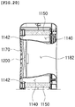
- FIG. 12 illustrates a state in which the discharge end 1142 of an air purifier 1100 according to example 4 is completely open
- FIG. 13 illustrates a state in which the discharge end 1142 is partially closed
- FIG. 14 illustrates a state in which an adjusting unit 1190 is installed in an inner periphery of the housing 1110
- FIG. 15 illustrates a state in which the adjusting unit 1190 is operated
- FIG. 16 is an exploded perspective view of the adjusting unit 1190
- FIGS. 17 and 18 illustrate a state in which a cover plate 1192 of the adjusting unit 1190 is operated.
- the air purifier 1100 may further include the adjusting unit 1190 for adjusting an opening area of the discharge end 1142 or shielding the discharge end 1142.
- the adjusting unit 1190 may be configured to adjust an outer diameter of the discharge end 1142.
- the adjusting unit 1190 may be configured to adjust an opening area of the annular discharge end 1142 by reducing or increasing an outer diameter of the discharge end 1142.
- the adjusting unit 1190 may include a case 1191, a plurality of cover plates 1192, a rotating frame 1193, a fixing frame 1194, and a frame driving member 1195.
- the case 1191 accommodates the plurality of cover plates 1192, the rotating frame 1193, the fixing frame 1194, and the frame driving member 1195, and thus may support the plurality of cover plates, the rotating frame, the fixing frame, and the frame driving member, on an interior of the housing 1110.
- a shape and structure of the case 1191, described above, are not particularly limited, and may be any shape and structure as long as the case is able to support the plurality of cover plates 1192, the rotating frame 1193, the fixing frame 1194, and the frame driving member 1195 on an interior of the housing 1110.
- a hole portion 1191a opening having a diameter larger than that of the discharge end 1142 to allow an annular discharge flow path to be extended to the discharge opening 1113 formed in the front cover 1112, may be provided in the case 1191.
- a limit guide 1191b for limiting a moving distance of a limit projection 1193b provided in the rotating frame 1193, to be described later, may be provided in the case 1191.
- the plurality of cover plates 1192 are installed in the case 1191 and provided at an outer edge of the discharge end 1142, and may be configured to be moved in a radial direction of the discharge end 1142.
- the plurality of cover plates 1192 cover a portion of the discharge end 1142 while moving in a radial direction of the discharge end 1142, thereby adjusting an outer diameter of the discharge end 1142.
- the plurality of cover plates 1192 are disposed at regular intervals along an outer edge of the discharge end 1142 to form an annulus as a whole.
- the cover plate 1192 may be provided in a flat and curved bar shape, and the plurality of cover plates 1192 may be disposed so that portions thereof overlap each other as illustrated in FIG. 16 .
- cover plate 1192 may be provided with a rotating shaft 1192a at an end of one side and may be provided with a guide projection 1192b at an end of the other side.
- the rotating shaft 1192a may be provided in the form of a projection protruding from one surface of the cover plate 1192
- the guide projection 1192b may be provided in the form of a projection protruding from the other surface of the cover plate 1192.
- the rotating shaft 1192a of the cover plate 1192 may be fastened to a shaft hole 1193a of the rotating frame 1193 to be rotated, and the guide projection 1192b of the cover plate 1192 may be fastened to be slid in a longitudinal direction of a guide groove 1194a to the guide groove 1194a of the fixing frame 1194.
- the rotating frame 1193 may be configured to be annular, and may be provided to be rotated in a circumferential direction in the case 1191.
- the rotating frame 1193 is disposed in one surface of the plurality of cover plates 1192, and may allow the plurality of cover plates 1192 to be disposed at regular intervals along an outer edge of the discharge end 1142 and may support a cover plate so as to allow each cover plate 1192 to be rotated in a radial direction of the discharge end 1142.
- the rotating frame 1193 may be provided with the shaft hole 1193a to which the rotating shaft 1192a of the plurality of cover plates 1192 may be fastened.
- a frame gear for receiving rotational force of the frame driving member 1195 may be provided at an edge of the rotating frame 1193.
- the limit projection 1193b for limiting an angle of rotation of the rotating frame 1193 by the limit guide 1191b of the case 1191 may be provided at an edge of the rotating frame 1193.
- the limit projection 1193b is caught by both ends of the limit guide 1191b to limit an angle of rotation of the rotating frame 1193, so the rotating frame 1193 may be only rotated within a range of the limit guide 1191b.
- the fixing frame 1194 is disposed in the other surface of the plurality of cover plates 1192, and may allow the plurality of cover plates 1192 to be rotated around respective rotating shafts 1192a according to rotation of the rotating frame 1193.
- the guide groove 1194a into which the guide projection 1192b of the cover plate 1192 is inserted to be slid may be formed in the fixing frame 1194.
- the guide groove 1194a may be formed as a long groove elongated in a radial direction of the fixing frame 1194.
- a position of the plurality of cover plates 1192, fastened to the rotating frame 1193 through the rotating shaft 1192a, may be moved in a direction of rotation of the rotating frame 1193.
- the guide projection 1192b of the plurality of cover plates 1192 is fastened to the guide groove 1194a of the fixing frame 1194.
- the plurality of cover plates 1192 may be able to rotate in a radial direction of the discharge end 1142 while maintaining a state in which the guide projection 1192b is fastened to the guide groove 1194a.
- an outer diameter of the discharge end 1142 may be adjusted according to a diameter of a circular opening formed by an inner edge of the plurality of cover plates 1192.
- the plurality of cover plates 1192 are disposed as illustrated in FIG. 17 , so an outer diameter of the discharge end 1142 may be increased.
- the plurality of cover plates 1192 are disposed as illustrated in FIG. 18 , so an outer diameter of the discharge end 1142 may be reduced.
- the plurality of cover plates 1192 are configured to adjust a diameter of a circular opening formed by an inner edge to be less than or equal to an inner diameter of the discharge end 1142, thereby airtightly sealing the discharge end 1142.
- the frame driving member 1195 is provided in the case 1191, and rotates the rotating frame 1193 so as to adjust an angle of rotation of the rotating frame 1193.
- the frame driving member 1195 may be configured to include the rotary gear 1195a engaged with a frame gear 1193c of the rotating frame 1193, and a stepping motor 1195b for rotating the rotary gear 1195a, but is not limited thereto.
- the frame driving member may include any mechanical element capable of rotating the rotating frame 1193.
- the air purifier 1100 adjusts an opening area of the discharge end 1142 through the adjusting unit 1190, thereby changing flow characteristics of discharged air.
- a narrower flow path may be formed, as compared to when the discharge end 1142 is completely open as illustrated in FIG. 12 .
- a flow rate of discharged air may be relatively increased.
- an air discharge shape may be narrowed, as compared to when the discharge end 1142 is completely open as illustrated in FIG. 12 .
- it is more effective when air is blown far away in a narrow range.
- FIG. 19 is a front perspective view of an air purifier 1100 according to example 5
- FIG. 20 is a side cross-sectional view illustrating a display unit 1200 included in the air purifier 1100 according to example 5.
- the air purifier 1100 may further include a display unit 1200 provided to cover a hollow portion of the air guide 1180, and displaying an operating state of the air purifier 1100 or having a control button.
- a circular display unit 1200 covering the through hole 1182 instead of the through hole 1182, may be provided in the housing 1110, in a manner different from the air purifier 1100 according to examples 1 to 4, illustrated in FIGS. 1 to 18 .
- the through hole 1182 formed as an empty space, is used as a display and a control panel, so a simple outer cover of a product is formed without separately providing a display and a control button in the housing 1110.
- aesthetic design sensibility of a device may be improved.
- the examples 1 to 5 are separately described as different examples in the above description, but the air purifier 1100 may be implemented as a form in which at least one of the examples 1 to 5, described previously, is merged.
- an air conditioner 2100 may include a housing 2110, a blower fan 2130, a guide frame 2140, an air processing unit 2150, a first air outlet 2165, a second air outlet 2175, and a flow path switching unit 2180.
- the housing 2110 may form an external cover of the air conditioner 2100 according to an exemplary embodiment, and may provide an internal space in which the blower fan 2130, the guide frame 2140, the air processing unit 2150, and the flow path switching unit 2180 are able to be installed.
- the housing 2110 may be configured to include a front cover 2112 and a rear cover 2114, as illustrated in FIG. 23 . Moreover, the front cover 2112 and the rear cover 2114 are attached to each other, thereby providing an internal space in which the blower fan 2130, the guide frame 2140, the air processing unit 2150, and the flow path switching unit 2180 are able to be installed.
- the housing 2110 may be provided with an air suction portion 2117 in which external air is sucked into an interior of the housing 2110.
- the air suction portion 2117 may be provided in the rear surface of the housing 2110, but is not limited thereto.
- an outer surface of the housing 2110 may be additionally provided with a pollution level sensor 2120 for measuring a pollution level of indoor air.
- the blower fan 2130 is provided in the housing 2110.
- the blower fan may generate air flow by allowing external air to be sucked into an interior of the housing 2110, to pass through the air processing unit 2150, to be described later, and to be discharged externally again through the first air outlet 2165 and the second air outlet 2175.
- the blower fan 2130 is disposed below the annular discharge flow path 2160 and the second air outlet 2175, and may discharge air upwardly.
- the blower fan 2130 may be disposed directly below an annular discharge flow path 2160, to be described later, as illustrated in FIG. 24 .
- the air processing unit 2150 to be described later, may be disposed directly below the second air outlet 2175, but is not limited thereto.
- the blower fan 2130 may be configured as a centrifugal fan having high suction static pressure and airflow performance.
- the blower fan 2130 may be a dual suction type fan, capable of sucking air in both directions, or may be a single suction type fan capable of sucking air in one direction.
- the guide frame 2140 in the form of a partition wall, may be provided in the housing 2110, and may guide air, discharged from the blower fan 2130, to the first air outlet 2165 and the second air outlet 2175.
- the guide frame 2140 may include a scroll portion 2141 surrounding a periphery of the blower fan 2130, and a dividing portion 2144 provided in an upper end of the scroll portion 2141 and dividing the annular discharge flow path 2160 and the second air outlet 2175.
- the scroll portion 2141 is configured to surround a periphery of the blower fan 2130, and thus may guide air, discharged in a circumferential direction of the blower fan 2130.
- a vent 2142 in which air, guided by the scroll portion 2141, is blown in a direction of the dividing portion 2144, may be provided in an upper end of the scroll portion 2141.
- an air inlet 2143 in which air flows into the blower fan 2130, may be provided in one surface of the scroll portion 2141, and a fan motor 2135 for rotating the blower fan 2130 may be provided in the center of the air inlet 2143, but is not limited thereto.
- the dividing portion 2144 may be provided with a partition frame 2145 for dividing a space in which the annular discharge flow path 2160, to be described later, is formed in an internal space of the housing 2110.
- the partition frame 2145 may be provided with a through opening 2146 in which an air guide 2167, to be described later, passes therethrough and is coupled thereto.
- the partition frame 2145 may be provided with an enclosure 2147, formed in a periphery of the through opening 2146, protruding from one surface of the partition frame 2145, and forming the annular discharge flow path 2160, to be described later.
- the enclosure 2147 may be provided in the form surrounding a remaining area, excluding an air inflow end 2161 of the annular discharge flow path 2160, of a periphery of the through opening 2146, and may allow the annular discharge flow path 2160 to be formed in an internal space surrounded thereby.
- the air processing unit 2150 is provided in the housing 2110, and may have at least one function of air purification, dehumidification, and humidification.
- the air processing unit 2150 may include an air purification filter with various functions such as dust particle collection, deodorization, virus removal, and the like, in the case of having an air purification function, may include a dehumidification filter or a heat exchanger, in the case of having a dehumidification function, and may include a humidification filter, a ultrasonic humidification unit, or a heating humidification unit, in the case of having a humidification function.
- an air purification filter with various functions such as dust particle collection, deodorization, virus removal, and the like, in the case of having an air purification function, may include a dehumidification filter or a heat exchanger, in the case of having a dehumidification function, and may include a humidification filter, a ultrasonic humidification unit, or a heating humidification unit, in the case of having a humidification function.
- the air processing unit 2150 may include an air purification filter together with a humidification filter, or an air purification filter together with a heat exchanger, thereby having a plurality of functions among an air purification function, a dehumidification function, and a humidification function.
- an air processing device may be implemented as a product such as an air purifier, a dehumidifier, a humidifier, a dehumidifying purifier, a humidifying purifier, and the like.
- the air processing unit 2150 is disposed in an air intake side of the blower fan 2130, and may process air, sucked into the blower fan 2130.
- the air processing unit 2150 may be disposed between the air inlet 2143 formed in the scroll portion 2141 of the guide frame 2140 and the air suction portion 2117 of the housing 2110, but is not limited thereto.
- the first air outlet 2165 may form a passage in which air inside the housing 2110, flowing by the blower fan 2130, is discharged externally.
- the first air outlet 2165 described above, may be provided in an annular shape, and an annular discharge end from which air is discharged may be formed in an end thereof.
- the first air outlet 2165 may be formed in one surface of the housing 2110.
- the annular discharge flow path 2160 may be formed in the housing 2110.
- the annular discharge flow path 2160 may be formed in the housing 2110 to allow an end of a discharge side, from which air is discharged, to form the first air outlet 2165, and to allow the first air outlet 2165 to be disposed in one surface of the housing 2110.
- the annular discharge flow path 2160 may be formed to be upwardly or downwardly inclined in a horizontal direction or toward a front of the housing 2110 in the housing 1110 to allow the first air outlet 2165 to be disposed in a front cover 2112 of the housing 1110.
- the annular discharge flow path 2160 may be formed in a cylindrical shape, horizontally or obliquely laid in the housing 2110, as a whole.
- the first air outlet 2165 may be provided in an annular shape in the front cover 2112 of the housing 2110 according to a shape of an end of the annular discharge flow path 2160.
- annular discharge flow path 2160 may be formed to have a cross section narrowing toward the first air outlet 2165 in the housing 2110, as illustrated in a cross-sectional view of FIG. 24 .
- an air guide 2167 may be provided in the housing 2110.
- the air guide 2167 is extended into an interior of the housing 2110, thereby forming the annular discharge flow path 2160.
- a discharge opening 2113 may be formed in one surface of the housing 2110.
- one end of the air guide 2167 is disposed in the center of the discharge opening 2113, and the other end thereof is extended into an interior of the housing 2110.
- an inner diameter of the annular discharge flow path 2160 may be formed.
- an interval between an edge of one end of the air guide 2167 and the discharge opening 2113 may form the first air outlet 2165 of the annular discharge flow path 2160.
- a space between an outer side surface of the air guide 2167 and the enclosure 2147 provided in the dividing portion 2144 of the guide frame 2140 may form the annular discharge flow path 2160.
- the air guide 2167 may be installed to pass through the through opening 2146 formed in the partition frame 2145 of the dividing portion 2144 of the guide frame 2140.
- the annular discharge flow path 2160 may be provided as a space surrounded by the air guide 2167, the enclosure 2147, and the partition frame 2145.
- the air inflow end 2161 in communication with the vent 2142 of the scroll portion 2141 may be provided in a lower end of the annular discharge flow path 2160.
- air discharged from the vent 2142 of the scroll portion 2141, flows into the annular discharge flow path 2160 through the air inflow end 2161, and is then discharged externally through the first air outlet 2165.
- the air guide 2167 may be configured so that an outer diameter increases from the other end to one end.
- the air guide 2167 may be configured to have any shape as long as the annular discharge flow path 2160 is formed to allow a cross section thereof to become narrower toward the first air outlet 2165.
- the air guide 2167 may be formed to have a cylindrical shape with the same diameter at both ends, and a shape of the enclosure 2147 may be formed to be narrower toward the first air outlet 2165.
- the air guide 2167 may be formed to have an outer diameter narrowing toward the first air outlet 2165, and a shape of the enclosure 2147 may be formed to be smaller by an amount of change larger than an amount of change in an outer diameter of the air guide 2167 toward the first air outlet 2165.
- the air guide 2167 may be extended from one surface to the other surface of the housing 2110, and may have a shape of a hollow horn.
- an opening 2115 corresponding to a hollow portion of the other end of the air guide 2167, may be formed in the other surface of the housing 2110, and the other end of the air guide 2167 may be connected to an edge of the opening 2115.
- a through hole 2168 passing from one surface to the other surface in the medium of the air guide 2167, may be formed in the housing 2110.
- air, discharged at a high rate of flow in the first air outlet 2165 generates a flow in air, present in the through hole 2168, and air, present in an outer edge of the first air outlet 2165, so a volume of air, discharged from the first air outlet 2165, may be increased.
- the air, discharged from the first air outlet 2165 has a relatively lower pressure than that of ambient air, that is, air inside the through hole 2168 and air at an outer edge of the first air outlet 2165, due to a high rate of flow, so the air inside the through hole 2168 and the air at an outer edge of the first air outlet 2165 may flow toward discharged air having a relatively low pressure.
- the second air outlet 2175 may form a passage in which air inside the housing 2110, flowed by the blower fan 2130, is discharged externally.
- the second air outlet 2175 is formed in an upper end of the housing 2110, and may form a path in which air, discharged upwardly from the blower fan 2130, flows almost linearly, and is then discharged to an upper end of the housing 2110.
- the flow path switching unit 2180 may be provided in the housing 2110, and may guide air, discharged from the blower fan 2130, to at least one of the first air outlet 2165 and the second air outlet 2175. In other words, the flow path switching unit 2180 switches a flow path of air in the housing 2110, thereby allowing air to be discharged to the first air outlet 2165 or the second air outlet 2175, or to be discharged to the first air outlet 2165 and the second air outlet 2175 at the same time.
- the flow path switching unit 2180 may be configured to open and close the air inflow end 2161 of the annular discharge flow path 2160 and the second air outlet 2175.
- the flow path switching unit 2180 may include an opening and closing door 2182 and a motor member 2186.
- the opening and closing door 2182 is provided to be rotated in the housing 2110, and may rotate to selectively open and close the air inflow end 2161 of the annular discharge flow path 2160 and the second air outlet 2175.
- the opening and closing door 2182 may be configured in the form of a curved plate provided at a branch point of the air inflow end 2161 of the annular discharge flow path 2160 and a flow path toward the second air outlet 2175, as illustrated in FIGS. 24 to 27 .
- the motor member 2186 is coupled to a rotating shaft 2222 of the opening and closing door 2182, and thus may adjust an angle of rotation of the opening and closing door 2182.
- opening and closing door 2182 allows the air inflow end 2161 of the annular discharge flow path 2160 to be open and shields the flow path toward the second air outlet 2175, as illustrated in FIG. 26 , air, blown from the blower fan 2130, may flow in the annular discharge flow path 2160 and may be only discharged to the first air outlet 2165.
- the opening and closing door 2182 allows the air inflow end 2161 of the annular discharge flow path 2160 and the flow path toward the second air outlet 2175 to be open, as illustrated in FIG. 27 , a portion of air, blown from the blower fan 2130, may be discharged to the first air outlet 2175, and a remaining portion thereof may be discharged to the second air outlet 2175.
- the air conditioner 2100 according to example 6, as described previously, has the advantage of having fast flow performance and high airflow performance of discharged air through the annular first air outlet 2165, in which a cross section of a flow path becomes narrower.
- the air conditioner 2100 according to example 6 is configured to selectively open at least one of the first air outlet 2165 and the second air outlet 2175 through the flow path switching unit 2180.
- the air conditioner 2100 is configured to selectively open at least one of the first air outlet 2165 and the second air outlet 2175 through the flow path switching unit 2180.
- air is discharged to the first air outlet 2165.
- air is discharged to the second air outlet 2175.
- FIG. 28 is a front perspective view of the air conditioner 2100 according to example 7.
- the air conditioner 2100 may include a grill member 2190 for guiding discharged air to the first air outlet 2165.
- the grill member 2190 is provided at regular intervals in the annular first air outlet 2165, and may be provided with a plurality of guide blades 2186, elongated in a discharge direction of discharged air.
- the grill member 2190 allows air flow of discharged air to have linearity or allows discharged air to flow spirally, through a shape of the plurality of guide blades 2186, thereby increasing a linear reaching distance of discharged air.
- the grill member 2190 may be configured to be attached to and detached from the front cover 2112 to be able to be separated from the housing 2110 and to be easily cleaned.
- the grill member 2190 may be integrally configured with the air guide 2167, and may be configured to be separated from the air guide 2167 so as to be independently separated from the air guide 2167 in the housing 2110.
- the blower fan 2130 may be exposed through the first air outlet 2165 and the air inflow end 2161.
- the structure, in which the blower fan 2130 is exposed may allow a foreign object to flow to the blower fan 2130 through the first air outlet 2165 and the air inflow end 2161, and there is a risk of a safety accident in which the user's hand may enter to the blower fan 2130.
- the flow path switching unit 2180 may be operated to automatically shield the first air outlet 2165 when the grill member 2190 and the air guide 2167 are separated from the housing 2110.
- the flow path switching unit 2180 may be operated to allow the opening and closing door 2182 to close the air inflow end 2161, when the grill member 2190 and the air guide 2167 are separated from the housing 2110.
- the housing 2110 may be provided with a mounting detection sensor (not shown) for sensing whether the grill member 2190 or the air guide 2167 is mounted, and the motor member 2186 of the flow path switching unit 2180 may receive a signal of the mounting detection sensor and allow the opening and closing door 2182 to be rotated so as to close the air inflow end 2161, when the grill member 2190 or the air guide 2167 is separated from the housing 2110.
- a mounting detection sensor not shown
- the motor member 2186 of the flow path switching unit 2180 may receive a signal of the mounting detection sensor and allow the opening and closing door 2182 to be rotated so as to close the air inflow end 2161, when the grill member 2190 or the air guide 2167 is separated from the housing 2110.
- FIGS. 29 and 30 are a front perspective view and a side cross-sectional view of the air conditioner 2100 according to example 8.
- the air conditioner 2100 according to example 8 may further include a display unit 2300 provided to cover a hollow portion of the air guide 2167, and displaying an operating state of the air conditioner 2100 or having a control button.
- a circular display unit 2300 covering the through hole 2168, instead of the through hole 2168, may be provided in the housing 2110, in a manner different from the air conditioner 2100 according to example 6 illustrated in FIGS. 21 to 27 .
- the through hole 2168 formed as an empty space, is used as a display and a control panel, so a simple outer cover of a product is formed without providing a separate display and a separate control button in the housing 2110.
- aesthetic design sensibility of a device may be improved.
- the display unit 2300 is illustrated to cover the entirety of the through hole 2168, but is not limited thereto.
- the display unit 2300 is configured in the form in which an outer edge thereof is spaced apart from an inner wall of the air guide 2167, and thus may be configured to form an air flow gap between the outer edge of the display unit 2300 and an inner side surface of the air guide 2167.
- FIG. 31 is a front view and a side cross-sectional view illustrating a state in which the first air outlet 2165 of the air conditioner 2100 according to example 9 is completely open
- FIG. 32 is a front view and a side cross-sectional view illustrating a state in which a portion of the first air outlet 2165 is closed
- FIG. 33 illustrates a state in which an adjusting unit 2200 is installed in the housing 2110
- FIG. 34 illustrates a state in which the adjusting unit 2200 is operated.
- FIG. 35 is an exploded perspective view of the adjusting unit 2200
- FIGS. 36 and 37 are views illustrating a state in which a cover plate 2220, provided in the adjusting unit 2200, is operated.
- the air conditioner 2100 may further include the adjusting unit 2200 for adjusting an opening area of the first air outlet 2165 or shielding the first air outlet 2165.
- the adjusting unit 2200 may be configured to adjust an outer diameter of the first air outlet 2165.
- the adjusting unit 2200 may be configured to adjust an opening area of the annular first air outlet 2165 by reducing or increasing an outer diameter of the first air outlet 2165.
- the adjusting unit 2200 may include a case 2210, a plurality of cover plates 2220, a rotating frame 2230, a fixing frame 2240, and a frame driving member 2250.
- the case 2210 accommodates the plurality of cover plates 2220, the rotating frame 2230, the fixing frame 2240, and the frame driving member 2250, and thus may support the plurality of cover plates, the rotating frame, the fixing frame, and the frame driving member, on an interior of the housing 2110.
- a shape and structure of the case 2210, described above, are not particularly limited, and may be any shape and structure as long as the case is able to support the plurality of cover plates 2220, the rotating frame 2230, the fixing frame 2240, and the frame driving member 2250 on an interior of the housing 2110.
- a hole portion 2212 opening having a diameter larger than that of the first air outlet 2165 to allow an annular discharge flow path to be extended to the discharge opening 2113 formed in the front cover 2112, may be provided in the case 2210.
- a limit guide 2214 for limiting a moving distance of a limit projection 2234 provided in the rotating frame 2230, to be described later, may be provided in the case 2210.
- the plurality of cover plates 2220 are installed in the case 2210 and provided at an outer edge of the first air outlet 2165, and may be configured to be moved in a radial direction of the first air outlet 2165.
- the plurality of cover plates 2220 cover a portion of the first air outlet 2165 while moving in a radial direction of the first air outlet 2165, thereby adjusting an outer diameter of the first air outlet 2165.
- the plurality of cover plates 2220 are disposed at regular intervals along an outer edge of the first air outlet 2165 to form an annulus as a whole.
- the cover plate 2220 may be provided in a flat and curved bar shape, and the plurality of cover plates 2220 may be disposed so that some of the plurality of cover plates overlap each other as illustrated in FIG. 35 .
- cover plate 2220 may be provided with a rotating shaft 2222 at an end of one side and may be provided with a guide projection 2224 at an end of the other side.
- the rotating shaft 2222 may be provided in the form of a projection protruding from one surface of the cover plate 2220
- the guide projection 2224 may be provided in the form of a projection protruding from the other surface of the cover plate 2220.
- the rotating shaft 2222 of the cover plate 2220 may be fastened to a shaft hole 2232 of the rotating frame 2230 to be rotated, and the guide projection 2224 of the cover plate 2220 may be fastened to be slid in a longitudinal direction of a guide groove 2242 to the guide groove 2242 of the fixing frame 2240.
- the rotating frame 2230 may be configured to be annular, and may be provided to be rotated in a circumferential direction in the case 2210.
- the rotating frame 2230 is disposed in one surface of the plurality of cover plates 2220, and may allow the plurality of cover plates 2220 to be disposed at regular intervals along an outer edge of the first air outlet 2165 and may support a cover plate so as to allow each cover plate 2220 to be rotated in a radial direction of the first air outlet 2165.
- the rotating frame 2230 may be provided with the shaft hole 2232 to which the rotating shaft 2222 of the plurality of cover plates 2220 may be fastened.
- a frame gear 2236 for receiving a rotational force of the frame driving member 2250 may be provided at an edge of the rotating frame 2230.
- the limit projection 2234 for limiting an angle of rotation of the rotating frame 2230 by the limit guide 2214 of the case 2210 may be provided at an edge of the rotating frame 2230.
- the limit projection 2234 is caught by both ends of the limit guide 2214 to limit an angle of rotation of the rotating frame 2230, so the rotating frame 2230 may be only rotated within a range of the limit guide 2214.
- the fixing frame 2240 is disposed in the other surface of the plurality of cover plates 2220, and may allow the plurality of cover plates 2220 to be rotated around respective rotating shafts 2222 according to rotation of the rotating frame 2230.
- the guide groove 2242 into which the guide projection 2224 of the cover plate 2220 is inserted to be slid may be formed in the fixing frame 2240.
- the guide groove 2242 may be formed as a long groove elongated in a radial direction of the fixing frame 2240.
- a position of the plurality of cover plates 2220, fastened to the rotating frame 2230 through the rotating shaft 2222, may be moved in a direction of rotation of the rotating frame 2230.
- the guide projection 2224 of the plurality of cover plates 2220 is fastened to the guide groove 2242 of the fixing frame 2240.
- the plurality of cover plates 2220 may be able to rotate in a radial direction of the first air outlet 2165 while maintaining a state in which the guide projection 2224 is fastened to the guide groove 2242.
- an outer diameter of the first air outlet 2165 may be adjusted according to a diameter of a circular opening formed by an inner edge of the plurality of cover plates 2220.
- the plurality of cover plates 2220 are disposed as illustrated in FIG. 36 , so an outer diameter of the first air outlet 2165 may be increased.
- the plurality of cover plates 2220 are disposed as illustrated in FIG. 37 , so an outer diameter of the first air outlet 2165 may be reduced.
- the plurality of cover plates 2220 are configured to adjust a diameter of a circular opening formed by an inner edge to be less than or equal to an inner diameter of the first air outlet 2165, thereby airtightly sealing the first air outlet 2165.
- the frame driving member 2250 is provided in the case 2210, and rotates the rotating frame 2230 so as to adjust an angle of rotation of the rotating frame 2230.
- the frame driving member 2250 may be configured to include the rotary gear 2252 engaged with a frame gear 2236 of the rotating frame 2230, and a stepping motor 2254 for rotating the rotary gear 2252, but is not limited thereto.
- the frame driving member may include any mechanical element capable of rotating the rotating frame 2230.
- the air conditioner 2100 adjusts an opening area of the first air outlet 2165 through the adjusting unit 2200, thereby changing flow characteristics of discharged air.
- a narrower flow path may be formed, as compared to when the first air outlet 2165 is completely open as illustrated in FIG. 31 .
- a flow rate of discharged air may be relatively increased.
- an air discharge shape may be narrowed, as compared to when the first air outlet 2165 is completely open, as illustrated in FIG. 31 .
- it is more effective when air is blown far away in a narrow range.
- FIG. 38 is a front perspective view of an air conditioner 2100 according to example 10
- FIG. 39 is a rear perspective view of the air conditioner 2100
- FIG. 40 is a side view of the air conditioner 2100
- FIGS. 41 and 42 are side cross-sectional views illustrating a state in which the flow path switching unit 2180 is operated
- FIG. 43 is a perspective view of the flow path switching unit 2180.
- the blower fan 2130 may be disposed directly below the second air outlet 2175, and the air processing unit 2150 may be disposed in front of the blower fan 2130.
- the air suction portion 2117 may be provided in a front surface of the housing 2110.
- a flow path of air, flowing from the blower fan 2130 to the second air outlet 2175 may be formed in a nearly linear form, and a flow path of air, flowing from the blower fan 2130 to the first air outlet 2165, may be provided in an inclined or bent form.
- the air conditioner according to example 10 has the advantage that air at higher pressure is able to be discharged from the second air outlet 2175, as compared to the air conditioner 2100 according to example 6, described previously with reference to FIGS. 21 to 27 . As discharge wind pressure of the second air outlet 2175 becomes higher, indoor air circulation performance is improved.
- the housing 2110 may be configured to allow the second air outlet 2175 to be located below the through hole 2168, in a manner different from the form of the housing 2110 of the air conditioner 2100 according to example 6.
- the rear cover 2114 of the housing 2110 may include an extension casing portion 2118, extended upwardly from an upper front portion of the second air outlet 2175 in an upper end and accommodating the air guide 2167 therein, and having the annular discharge flow path 2160 formed therein, as illustrated in FIGS. 38 to 40 .
- the extension casing portion 2118 may form a portion of a rear surface of the housing 2110, and the through hole 2168 may be formed in the medium of the air guide 2167 in the extension casing portion 2118 of a front cover 2112 and a rear cover 2114.
- a length of an air flow path, connected from a discharge side of the blower fan 2130 to the second air outlet 2175, is short, so there may be an advantage in that pressure loss of air, discharged from the second air outlet 2175, is less.
- pressure loss due to a long flow distance to air, flowing in a flow path between a discharge side of the blower fan 2130, formed in the housing 2110, and the second air outlet 2175, may occur in air.
- the opening and closing door 2182 of the flow path switching unit 2180 may be provided to have a flat plate shape having a rotating shaft 2222 in one end, as illustrated in FIGS. 41 to 43 .
- the opening and closing door 2182 has a rotating shaft 2222 between the air inflow end 2161 of the annular discharge flow path 2160 and the second air outlet 2175. Moreover, while the opening and closing door rotates, the opening and closing door is able to shield the air inflow end 2161 of the annular discharge flow path 2160 or to shield the second air outlet 2175.
- the opening and closing door 2182 having a flat plate shape, described above, may be shaken due to a pressure of air, blown from the blower fan 2130, and thus may generate a noise, in a case in which the opening and closing door is disposed to shield the air inflow end 2161 of the annular discharge flow path 2160 and the second air outlet 2175.
- the opening and closing door 2182 disposed to cover the second air outlet 2175, is resistant to air, blown from the blower fan 2130, while having a planar form, thereby receiving a significant amount of air pressure.
- the opening and closing door 2182 may have a magnet 2184 in a body thereof, and a magnetic body (for example, iron (Fe)), receiving a suction force caused by magnetic force of the magnet 2184 provided on the opening and closing door 2182, may be provided in the air inflow end 2161 of the annular discharge flow path 2160 and the second air outlet 2175.
- a magnetic body for example, iron (Fe)
- the opening and closing door 2182 is adsorbed by a magnetic body through suction force caused by magnetic force of the magnet 2184 when being disposed to cover the air inflow end 2161 and the second air outlet 2175.
- the opening and closing door may be fixed without a fluctuation.
- a magnetic body, provided in the air inflow end 2161 of the annular discharge flow path 2160, may be coupled to a frame in the housing 2110, forming the air inflow end 2161, and a magnetic body, provided in the second air outlet 2175, may be provided as an iron perforated net member 2177 mounted to cover the second air outlet 2175.
- the perforated net member 2177 is mounted to cover the second air outlet 2175, thereby allowing air to pass while preventing a foreign object from flowing into the second air outlet 2175.
- the examples 6 to 10 are separately described as different examples in the above description, but the air conditioner 2100 may be implemented in a form in which at least one of the examples 6 to 10, described previously, is merged.
Abstract
Description
- The present disclosure relates to an air purifier, and particularly, to an air purifier capable of quickly circulating indoor air.
- An air purifier according to the related art has a structure for blowing air through a discharge port which is open in a circular or polygonal form in the front or upper end of a product.
- In the air purifier according to the related art, described above, due to a wide opening area of a discharge port, a volume of air per unit time may be large. However, there may be a disadvantage, in that a flow rate of discharged air may be low, so that a speed for circulating indoor air is low. In this case, to increase a flow rate, the number of revolutions of a fan is required to be increased. However, there may be a disadvantage in that noise is generated due to the number of revolutions of a fan being increased.
- Meanwhile, when an area of a discharge port is reduced to solve the disadvantages described above, a volume of air is small and air is discharged through a small area. Thus, there is a disadvantage in that an indoor air circulation speed may be low.
- An aspect of the present disclosure may provide an air purifier for securing a large volume of air and high rate of flow of discharged air and achieving improvement in aesthetic design of a product.
- An aspect of the present disclosure may provide an air purifier capable of using an entire area of a filter in a balanced manner.
- An aspect of the present disclosure may provide an air purifier capable of adjusting a flow rate and a discharge form of discharged air.
- According to an aspect of the present disclosure, an air purifier includes: a housing; a blower fan provided in the housing; and an annular discharge flow path, configuring a path through which air, inside the housing flowing by the blower fan, is discharged externally, formed in the housing while having an annular discharge end, and having a cross section, narrowing from an interior of the housing to the discharge end.
- According to an aspect of the present disclosure, an air conditioner includes: a housing; a blower fan provided in the housing; and an annular first air outlet, configuring a passage through which air, flowing in the housing by the blower fan, is discharged externally, and having an annular discharge end; a second air outlet, configuring a passage through which air, flowing in the housing by the blower fan, is discharged externally; and a flow path switching unit, provided in the housing, and guiding the air, discharged by the blower fan, to at least one of the first air outlet and the second air outlet.
- According to an exemplary embodiment in the present disclosure, a fast flow rate and a large volume of air of discharged air may be secured.
- According to an exemplary embodiment in the present disclosure, an entire area of a cylindrical filter may be used in a balanced manner, so a service lift of a cylindrical filter may be improved.
- According to an exemplary embodiment in the present disclosure, an area of an air outlet is adjusted, so a flow rate and a discharge form of discharged air may be adjusted.
-
-
FIG. 1 is a front perspective view of an air purifier according to example 1; -
FIG. 2 is a rear perspective view of an air purifier according to example 1; -
FIG. 3 is a front view of an air purifier according to example 1; -
FIG. 4 is a side view of an air purifier according to example 1; -
FIG. 5 is a rear view of an air purifier according to example 1; -
FIG. 6 is an exploded perspective view of an air purifier according to example 1; -
FIG. 7 is a side cross-sectional view of an air purifier according to example 1; -
FIG. 8 is a perspective view of a grill member included in an air purifier according to example 1; -
FIG. 9 is a front perspective view of an air purifier according to example 2; -
FIG. 10 is a front cross-sectional view illustrating an internal configuration of an air purifier according to example 3; -
FIG. 11 is a perspective view of a driving unit included in an air purifier according to example 3; -
FIG. 12 is a front view and a side cross-sectional view, illustrating a discharge end in a state in which the discharge end of an air purifier according to example 4 is completely open; -
FIG. 13 is a front view and a side cross-sectional view, illustrating a discharge end in a state in which the discharge end of an air purifier according to example 4 is partially closed; -
FIG. 14 is a drawing illustrating a state in which an adjusting unit, included in an air purifier according to example 4, is installed in a housing; -
FIG. 15 is a perspective view of an operating state of an adjusting unit included in an air purifier according to example 4; -
FIG. 16 is an exploded perspective view of an adjusting unit included in an air purifier according to example 4; -
FIG. 17 is a drawing illustrating an operating state of a cover plate of an adjusting unit included in an air purifier according to example 4; -
FIG. 18 is a drawing illustrating an operating state of a cover plate of an adjusting unit included in an air purifier according to example 4; -
FIG. 19 is a front perspective view of an air purifier according to example 5; -
FIG. 20 is a side cross-sectional view of a display unit included in an air purifier according to example 5; -
FIG. 21 is a front perspective view of an air conditioner according to example 6; -
FIG. 22 is a rear perspective view of an air conditioner according to example 6; -
FIG. 23 is an exploded perspective view of an air conditioner according to example 6; -
FIG. 24 is a side cross-sectional view of an air conditioner according to example 6; -
FIGS. 25 to 27 are side cross-sectional views illustrating an operating state of a flow path switching unit included in an air conditioner according to example 6; -
FIG. 28 is a front perspective view of an air conditioner according to example 7; -
FIG. 29 is a front perspective view of an air conditioner according to example 8; -
FIG. 30 is a side cross-sectional view of an air conditioner according to example 8; -
FIG. 31 is a front view and a side cross-sectional view, illustrating a first air outlet of an air conditioner according to example 9 is completely open; -
FIG. 32 is a front view and a side cross-sectional view, illustrating a first air outlet of an air conditioner according to example 9 is partially closed; -
FIG. 33 is a drawing illustrating a state in which an adjusting unit, included in an air conditioner according to example 9, is installed in a housing; -
FIG. 34 is a perspective view of an operating state of an adjusting unit included in an air conditioner according to example 9; -
FIG. 35 is an exploded perspective view of an adjusting unit included in an air conditioner according to example 9; -
FIGS. 36 and37 are drawings illustrating an operating state of a cover plate of an adjusting unit included in an air conditioner according to example 9; -
FIG. 38 is a front perspective view of an air conditioner according to example 10; -
FIG. 39 is a rear perspective view of an air conditioner according to example 10; -
FIG. 40 is a side view of an air conditioner according to example 10; -
FIGS. 41 to 42 are cross-sectional views illustrating an operating state of a flow path switching unit included in an air conditioner according to example 10; and -
FIG. 43 is a perspective view illustrating a flow path switching unit included in an air conditioner according to example 10. - The terminology used herein is for the purpose of describing particular embodiments only and is not intended to be limiting of the invention. Furthermore, the singular expressions herein include plural expressions unless the context clearly indicates otherwise.
- Hereinafter, preferred embodiments of the present invention will be described with reference to the accompanying drawings.
- First, with reference to
FIGS. 1 to 8 , example 1 will be described. - As illustrated in
FIGS. 1 to 8 , anair purifier 1100 according to an exemplary embodiment may include ahousing 1110, ablower fan 1130, an annulardischarge flow path 1140, afilter member 1150, and agrill member 1170. - The
housing 1110 may form an external cover of theair purifier 1100 according to an exemplary embodiment, and may provide an internal space in which theblower fan 1130 and thefilter member 1150 are able to be installed, and may be provided with the annulardischarge flow path 1140 formed therein. - In an exemplary embodiment, the
housing 1110 may be configured to include afront cover 1112 and arear cover 1114, as illustrated inFIG. 6 . Moreover, thefront cover 1112 and therear cover 1114 are attached to each other, thereby providing an internal space in which theblower fan 1130 and thefilter member 1150 are able to be installed. - In addition, the
housing 1110 may be provided with anair suction portion 1117 in which external air is sucked into an interior of thehousing 1110. In an exemplary embodiment, theair suction portion 1117 may be provided in each of a front surface and a rear surface of thehousing 1110, corresponding to ablower fan 1130 for sucking air in both directions, to be described later, but is not limited thereto. - In addition, in an exemplary embodiment, an outer surface of the
housing 1110 may be provided with apollution level sensor 1120 for measuring a pollution level of indoor air. - The
blower fan 1130 is provided in thehousing 1110. In this case, during an operation of the blower fan, the blower fan may generate air flow by allowing external air to be sucked into an interior of thehousing 1110, to flow in the annulardischarge flow path 1140, to be described later, and to be discharged externally again through adischarge end 1142. - The
blower fan 1130, described above, may allow air to flow into the annulardischarge flow path 1140 in at least one of upward, downward, and sideward directions of the annulardischarge flow path 1140, to be described later. - In examples 1 to 5 illustrated in
FIGS. 1 to 20 , a structure, in which a discharge side of theblower fan 1130 is disposed downwardly of the annulardischarge flow path 1140 to allow air to flow in a lower end of the annulardischarge flow path 1140, is disclosed, but is not limited thereto. - Meanwhile, in an exemplary embodiment, the
blower fan 1130 may be configured as a centrifugal fan having high suction static pressure and airflow performance. - In this case, the
blower fan 1130 may be a type of fan capable of sucking air in both directions, but is not limited thereto. - The annular
discharge flow path 1140 is formed in thehousing 1110, and may form a path in which air, flowing by theblower fan 1130 in thehousing 1110, is discharged externally of thehousing 1110. - The annular
discharge flow path 1140, described above, may be formed to allow theannular discharge end 1142, that is, an end of a flow path, to be disposed in one surface of thehousing 1110. - In an exemplary embodiment, the annular
discharge flow path 1140 may be formed to be upwardly or downwardly inclined in a horizontal direction or toward a front of thehousing 1100 in thehousing 1110 to allow thedischarge end 1142 to be disposed in a front surface of thehousing 1100. Thus, the annulardischarge flow path 1140 may be formed in a cylindrical shape, horizontally laid in thehousing 1110, as a whole. - Here, the
discharge end 1142 of the annulardischarge flow path 1140 is disposed to be exposed to a front surface of thehousing 1110, and serves as an air outlet for discharging air, in thehousing 1110, to an interior. In this case, the discharge end is provided in an annular shape, according to a shape of an end of the annulardischarge flow path 1140. - Meanwhile, the annular
discharge flow path 1140, described above, is formed to have a cross section narrowing toward thedischarge end 1142 in thehousing 1110, as illustrated in a cross-sectional view ofFIG. 7 . - To form the
annular discharge end 1142 described above, anair guide 1180 may be provided in thehousing 1110 in an exemplary embodiment. - The
air guide 1180 is extended into an interior of thehousing 1110, thereby forming the annulardischarge flow path 1140. - In detail, a
discharge opening 1113, circularly open, may be formed in one surface of thehousing 1110. Moreover, one end of theair guide 1180 is disposed in the center of thedischarge opening 1113, and the other end thereof is extended into an interior of thehousing 1110. Thus, an inner diameter of the annulardischarge flow path 1140 may be formed. - In this case, an interval between an edge of one end of the
air guide 1180 and thedischarge opening 1113 may form thedischarge end 1142 of the annulardischarge flow path 1140. - In addition, a space between an outer side surface of the
air guide 1180 and an inner wall of thehousing 1110, or a space between an outer side surface of theair guide 1180 and thefilter member 1150, to be described later, may form the annulardischarge flow path 1140. - In addition, the
air guide 1180 may be formed to have an outer diameter, increasing from the other end to one end, to allow a cross section of the annulardischarge flow path 1140 to be narrower toward thedischarge end 1142. - In addition, in an exemplary embodiment, the
air guide 1180 may be extended from one surface to the other surface of thehousing 1110, and may have a shape of a hollow horn. - In this case, an
opening 1115, corresponding to a hollow portion of the other end of theair guide 1180, may be formed in the other surface of thehousing 1110, and the other end of theair guide 1180 may be connected to an edge of theopening 1115. - Through the structure described above, a through
hole 1182, passing from one surface to the other surface in the medium of theair guide 1180, may be formed in thehousing 1110. - Meanwhile, the
air guide 1180 is not limited to having a form in which an outer diameter increases from the other end to one end as described previously, but may be configured to have any form as long as the annulardischarge flow path 1140 has a cross section narrowing toward thedischarge end 1142. - For example, the
air guide 1180 may be formed to have a cylindrical shape with the same diameter at both ends, and a shape of an inner wall of thehousing 1110 or thefilter member 1150 may be formed to be narrower toward one end of theair guide 1180 . Alternatively, theair guide 1180 may be formed to have an outer diameter narrowing from the other end to one end, and a shape of an inner wall of thehousing 1110 or thefilter member 1150 may be formed to be smaller by a larger amount of change as compared to an amount of change in an outer diameter of theair guide 1180 toward one end of theair guide 1180. - The
filter member 1150 may be disposed in the annulardischarge flow path 1140, thereby purifying air being in taken or flowing in the annulardischarge flow path 1140. - The
filter member 1150, described above, may be provided with various functional filters, capable of removing large dust particles, fine dust particles, viruses and odors, and the like, contained in air passing there through. In addition, thefilter member 1150 may include a single filter having a single air purifying function, or may include a filter assembly, in which a plurality of filters, having various functions, respectively, overlap. - Meanwhile, in an exemplary embodiment, the
filter member 1150 may have a cylindrical shape, surrounding a periphery of theair guide 1180. - Here, air, discharged from the
blower fan 1130, passes through thefilter member 1150 and then flows in the annulardischarge flow path 1140, in a circumference of thefilter member 1150. - In this case, if a sufficient gap between the
filter member 1150 and theair guide 1180 is not secured, filter resistance increases, so air cannot smoothly pass through thefilter member 1150. In an exemplary embodiment, thefilter member 1150 is preferably configured to have an inner side surface spaced apart from an outer side surface of theair guide 1180 by a predetermined distance or more. Here, a separation distance between an inner side surface of thefilter member 1150 and an outer side surface of theair guide 1180 may be set to various values, according to the design specifications of a device. - In addition, here, a gap between the
filter member 1150 and theair guide 1180 may form the annulardischarge flow path 1140. - Meanwhile, although not illustrated therein, in another exemplary embodiment, a filter member is disposed in an air intake side of the
blower fan 1130, and thus may be configured to purify air, flowing in theblower fan 1130. The filter member, described above, does not have a cylindrical shape disposed in the annulardischarge flow path 1140 as illustrated previously, but may have a flat plate shape disposed between theair suction portion 1117 and an air intake side of theblower fan 1130 in thehousing 1110. - In another exemplary embodiment described above, a
cylindrical filter member 1150 may be excluded from the annulardischarge flow path 1140. - The
grill member 1170 is provided in thedischarge end 1142, and may guide air discharged from thedischarge end 1142. - In an exemplary embodiment, the
grill member 1170 is provided at regular intervals in theannular discharge end 1142, and may be provided with a plurality ofguide blades 1172, elongated in a discharge direction of discharged air. - The
grill member 1170, described above, allows air flow of discharged air to have linearity or allows discharged air to flow spirally, through a shape of the plurality ofguide blades 1172, thereby increasing a linear reaching distance of discharged air. - Alternatively, if the
discharge end 1142 is simply annularly open without thegrill member 1170, there may be a disadvantage in which air, discharged from thedischarge end 1142, is diffused in a radial direction of thedischarge end 1142. - The
air purifier 1100 according to an exemplary embodiment as described previously may discharge air at a high rate of flow, since, as air, flowing along the annulardischarge flow path 1140, flows toward thedischarge end 1142, a flow rate of the air increases. For reference, Bernoulli's theorem shows that a flow rate increases, when air passes through a narrow cross section. - In addition, in the
air purifier 1100 according to an exemplary embodiment, air, discharged at a high rate of flow in thedischarge end 1142, generates a flow in air, present in the throughhole 1182, and air, present in an outer edge of thedischarge end 1142, so high airflow performance may be obtained. - In detail, the air, discharged from the
discharge end 1142, has a relatively lower pressure than that of ambient air, that is, air inside the throughhole 1182 and air at an outer edge of thedischarge end 1142, due to a high rate of flow, so the air inside the throughhole 1182 and the air at an outer edge of thedischarge end 1142 may flow toward discharged air having a relatively low pressure. - Thus, the
air purifier 1100 according to an exemplary embodiment may secure a high rate of flow and a large volume of air. -
FIG. 9 is a front perspective view of anair purifier 1100 according to example 2. - Referring to
FIG. 9 , anair purifier 1100 according to example 2 may have ahousing 1110 configured in the form of a rectangular box, in a manner different from theair purifier 1100 according to example 1. - In other words, in the
air purifier 1100 according to various exemplary embodiments, an outer cover of thehousing 1110 is not limited to having a rounded shape, corresponding to theannular discharge end 1142. As illustrated inFIG. 9 , while thedischarge end 1142 is maintained in an annular shape, the outer cover of thehousing 1110 may be configured in various forms. - In addition, to configure a simple external cover of a device, the
air suction portion 1117 may be excluded from a front surface of thehousing 1110, and may be formed in a side surface of thehousing 1110. - Referring to
FIGS. 10 and11 , anair purifier 1100 according to example 3 will be described. - Here,
FIG. 10 is a front cross-sectional view illustrating an internal configuration of theair purifier 1100 according to example 3, andFIG. 11 is a perspective view of adriving unit 1160. - As illustrated in
FIGS. 10 and11 , in an exemplary embodiment, thefilter member 1150 is configured to surround the annulardischarge flow path 1140. Thus, a portion of the filter member in a circumferential direction is disposed between a discharge side of theblower fan 1130 and the annulardischarge flow path 1140, and the filter member may be configured to be rotated in a circumferential direction of the annulardischarge flow path 1140. - In an exemplary embodiment, the
blower fan 1130 blows air in one side of the annulardischarge flow path 1140, so an air concentration section S, disposed between theblower fan 1130 and the annulardischarge flow path 1140, may be generated in thefilter member 1150. - Here, the air concentration section S is a portion of a circumference of the
filter member 1150, disposed closest to theblower fan 1130, and is a portion through which a largest amount of air passes intensively, since air discharged from theblower fan 1130 passes through thefilter member 1150 in a substantially linear form. - In the structure described above, when the
blower fan 1130 is operated for a long period of time, air is only concentrated in a specific portion of thefilter member 1150, so an amount of dust particles collected in an air concentrated portion is larger as compared to that in other portions. Thus, the service time of thefilter member 1150 may become partially uneven, and air processing performance may be degraded. - To solve this, the
air purifier 1100 according to example 3 may be configured to allow the air concentration section S to be periodically changed by periodically rotating thefilter member 1150, when theblower fan 1130 is operated. - To this end, in an exemplary embodiment, a
driving unit 1160 for rotating thefilter member 1150 in a circumferential direction may be provided in thehousing 1110. - In an exemplary embodiment, as illustrated in
FIG. 11 , thedriving unit 1160 may be configured to include an annular drivenframe 1162 fastened to one end of thefilter member 1150, and installed to be rotated in a circumferential direction in thehousing 1110, and afilter drive member 1165 for rotating the drivenframe 1162 in a circumferential direction. - For example, as illustrated in
FIG. 11 , a drivengear 1163 may be provided at an edge of the drivenframe 1162, and thefilter drive member 1165 may include apower transmission gear 1166 engaged with a gear of the drivenframe 1162 as well as amotor member 1167 for rotating thepower transmission gear 1166, but is not limited thereto. - Meanwhile, the
air purifier 1100 according to example 3 is provided with a control unit (not shown) for controlling thefilter drive member 1165, and the control unit may be operated to change the air concentration section S by periodically rotating thefilter member 1150 based on the operating time of the blowingfan 1130, the operating speed, and the measured value of thepollution level sensor 1120. - Referring to
FIGS. 12 and18 , anair purifier 1100 according to example 4 will be described. - Here,
FIG. 12 illustrates a state in which thedischarge end 1142 of anair purifier 1100 according to example 4 is completely open,FIG. 13 illustrates a state in which thedischarge end 1142 is partially closed,FIG. 14 illustrates a state in which anadjusting unit 1190 is installed in an inner periphery of thehousing 1110,FIG. 15 illustrates a state in which theadjusting unit 1190 is operated,FIG. 16 is an exploded perspective view of theadjusting unit 1190, as well asFIGS. 17 and18 illustrate a state in which acover plate 1192 of theadjusting unit 1190 is operated. - As illustrated in
FIGS. 12 to 18 , theair purifier 1100 according to example 4 may further include theadjusting unit 1190 for adjusting an opening area of thedischarge end 1142 or shielding thedischarge end 1142. - In an exemplary embodiment, the
adjusting unit 1190 may be configured to adjust an outer diameter of thedischarge end 1142. In other words, theadjusting unit 1190 may be configured to adjust an opening area of theannular discharge end 1142 by reducing or increasing an outer diameter of thedischarge end 1142. - To implement the operation described above, in an exemplary embodiment, the
adjusting unit 1190 may include acase 1191, a plurality ofcover plates 1192, arotating frame 1193, afixing frame 1194, and aframe driving member 1195. - The
case 1191 accommodates the plurality ofcover plates 1192, therotating frame 1193, the fixingframe 1194, and theframe driving member 1195, and thus may support the plurality of cover plates, the rotating frame, the fixing frame, and the frame driving member, on an interior of thehousing 1110. A shape and structure of thecase 1191, described above, are not particularly limited, and may be any shape and structure as long as the case is able to support the plurality ofcover plates 1192, therotating frame 1193, the fixingframe 1194, and theframe driving member 1195 on an interior of thehousing 1110. - In an exemplary embodiment, a
hole portion 1191a, opening having a diameter larger than that of thedischarge end 1142 to allow an annular discharge flow path to be extended to thedischarge opening 1113 formed in thefront cover 1112, may be provided in thecase 1191. - In addition, in an exemplary embodiment, a
limit guide 1191b for limiting a moving distance of alimit projection 1193b provided in therotating frame 1193, to be described later, may be provided in thecase 1191. - The plurality of
cover plates 1192 are installed in thecase 1191 and provided at an outer edge of thedischarge end 1142, and may be configured to be moved in a radial direction of thedischarge end 1142. - The plurality of
cover plates 1192 cover a portion of thedischarge end 1142 while moving in a radial direction of thedischarge end 1142, thereby adjusting an outer diameter of thedischarge end 1142. - In an exemplary embodiment, the plurality of
cover plates 1192 are disposed at regular intervals along an outer edge of thedischarge end 1142 to form an annulus as a whole. - To this end, in an exemplary embodiment, the
cover plate 1192 may be provided in a flat and curved bar shape, and the plurality ofcover plates 1192 may be disposed so that portions thereof overlap each other as illustrated inFIG. 16 . - In addition, the
cover plate 1192 may be provided with arotating shaft 1192a at an end of one side and may be provided with aguide projection 1192b at an end of the other side. Here, therotating shaft 1192a may be provided in the form of a projection protruding from one surface of thecover plate 1192, while theguide projection 1192b may be provided in the form of a projection protruding from the other surface of thecover plate 1192. - In the configuration described above, the
rotating shaft 1192a of thecover plate 1192 may be fastened to ashaft hole 1193a of therotating frame 1193 to be rotated, and theguide projection 1192b of thecover plate 1192 may be fastened to be slid in a longitudinal direction of aguide groove 1194a to theguide groove 1194a of thefixing frame 1194. - The
rotating frame 1193 may be configured to be annular, and may be provided to be rotated in a circumferential direction in thecase 1191. - The
rotating frame 1193, described above, is disposed in one surface of the plurality ofcover plates 1192, and may allow the plurality ofcover plates 1192 to be disposed at regular intervals along an outer edge of thedischarge end 1142 and may support a cover plate so as to allow eachcover plate 1192 to be rotated in a radial direction of thedischarge end 1142. - In an exemplary embodiment, the
rotating frame 1193 may be provided with theshaft hole 1193a to which therotating shaft 1192a of the plurality ofcover plates 1192 may be fastened. - In addition, in an exemplary embodiment, a frame gear for receiving rotational force of the
frame driving member 1195 may be provided at an edge of therotating frame 1193. - In addition, in an exemplary embodiment, the
limit projection 1193b for limiting an angle of rotation of therotating frame 1193 by thelimit guide 1191b of thecase 1191 may be provided at an edge of therotating frame 1193. Thelimit projection 1193b is caught by both ends of thelimit guide 1191b to limit an angle of rotation of therotating frame 1193, so therotating frame 1193 may be only rotated within a range of thelimit guide 1191b. - The fixing
frame 1194 is disposed in the other surface of the plurality ofcover plates 1192, and may allow the plurality ofcover plates 1192 to be rotated around respective rotatingshafts 1192a according to rotation of therotating frame 1193. - To this end, the
guide groove 1194a into which theguide projection 1192b of thecover plate 1192 is inserted to be slid may be formed in thefixing frame 1194. Theguide groove 1194a may be formed as a long groove elongated in a radial direction of thefixing frame 1194. - In the configuration described above, when the
rotating frame 1193 is rotated, a position of the plurality ofcover plates 1192, fastened to therotating frame 1193 through therotating shaft 1192a, may be moved in a direction of rotation of therotating frame 1193. - In this case, the
guide projection 1192b of the plurality ofcover plates 1192 is fastened to theguide groove 1194a of thefixing frame 1194. Thus, to compensate for a change in distance between theshaft hole 1193a, to which therotating shaft 1192a is fastened, and theguide groove 1194a, to which theguide projection 1192b is fastened, due to rotation of therotating frame 1193, the plurality ofcover plates 1192 may be able to rotate in a radial direction of thedischarge end 1142 while maintaining a state in which theguide projection 1192b is fastened to theguide groove 1194a. - Here, when the plurality of
cover plates 1192 are rotated in a radial direction of thedischarge end 1142, an outer diameter of thedischarge end 1142 may be adjusted according to a diameter of a circular opening formed by an inner edge of the plurality ofcover plates 1192. - For example, when the
rotating frame 1193 rotates in one direction, the plurality ofcover plates 1192 are disposed as illustrated inFIG. 17 , so an outer diameter of thedischarge end 1142 may be increased. When therotating frame 1193 rotates in the other direction, the plurality ofcover plates 1192 are disposed as illustrated inFIG. 18 , so an outer diameter of thedischarge end 1142 may be reduced. - In an exemplary embodiment, the plurality of
cover plates 1192 are configured to adjust a diameter of a circular opening formed by an inner edge to be less than or equal to an inner diameter of thedischarge end 1142, thereby airtightly sealing thedischarge end 1142. - Meanwhile, the
frame driving member 1195 is provided in thecase 1191, and rotates therotating frame 1193 so as to adjust an angle of rotation of therotating frame 1193. - For example, the
frame driving member 1195 may be configured to include therotary gear 1195a engaged with aframe gear 1193c of therotating frame 1193, and a steppingmotor 1195b for rotating therotary gear 1195a, but is not limited thereto. In addition, the frame driving member may include any mechanical element capable of rotating therotating frame 1193. - Meanwhile, the
air purifier 1100 according to example 4, as described previously, adjusts an opening area of thedischarge end 1142 through theadjusting unit 1190, thereby changing flow characteristics of discharged air. - In detail, when a portion of the
discharge end 1142 is closed as illustrated inFIG. 13 , a narrower flow path may be formed, as compared to when thedischarge end 1142 is completely open as illustrated inFIG. 12 . Thus, a flow rate of discharged air may be relatively increased. - Moreover, when a portion of the
discharge end 1142 is closed as illustrated inFIG. 13 , an air discharge shape may be narrowed, as compared to when thedischarge end 1142 is completely open as illustrated inFIG. 12 . Thus, it is more effective when air is blown far away in a narrow range. - Referring to
FIGS. 19 and20 , anair purifier 1100 according to example 5 will be described.FIG. 19 is a front perspective view of anair purifier 1100 according to example 5, andFIG. 20 is a side cross-sectional view illustrating adisplay unit 1200 included in theair purifier 1100 according to example 5. - As illustrated in
FIGS. 19 to 20 , theair purifier 1100 according to example 5 may further include adisplay unit 1200 provided to cover a hollow portion of theair guide 1180, and displaying an operating state of theair purifier 1100 or having a control button. - In other words, in the
air purifier 1100 according to example 5, acircular display unit 1200 covering the throughhole 1182, instead of the throughhole 1182, may be provided in thehousing 1110, in a manner different from theair purifier 1100 according to examples 1 to 4, illustrated inFIGS. 1 to 18 . - In the
air purifier 1100 according to example 5, described above, the throughhole 1182, formed as an empty space, is used as a display and a control panel, so a simple outer cover of a product is formed without separately providing a display and a control button in thehousing 1110. Thus, aesthetic design sensibility of a device may be improved. - Meanwhile, the examples 1 to 5 are separately described as different examples in the above description, but the
air purifier 1100 may be implemented as a form in which at least one of the examples 1 to 5, described previously, is merged. - First, with reference to
FIGS. 21 to 27 , an example 6 will be described. - As illustrated in
FIGS. 21 to 27 , anair conditioner 2100 according to an exemplary embodiment may include ahousing 2110, ablower fan 2130, aguide frame 2140, anair processing unit 2150, afirst air outlet 2165, asecond air outlet 2175, and a flowpath switching unit 2180. - The
housing 2110 may form an external cover of theair conditioner 2100 according to an exemplary embodiment, and may provide an internal space in which theblower fan 2130, theguide frame 2140, theair processing unit 2150, and the flowpath switching unit 2180 are able to be installed. - In an exemplary embodiment, the
housing 2110 may be configured to include afront cover 2112 and arear cover 2114, as illustrated inFIG. 23 . Moreover, thefront cover 2112 and therear cover 2114 are attached to each other, thereby providing an internal space in which theblower fan 2130, theguide frame 2140, theair processing unit 2150, and the flowpath switching unit 2180 are able to be installed. - In addition, the
housing 2110 may be provided with anair suction portion 2117 in which external air is sucked into an interior of thehousing 2110. - In an exemplary embodiment, the
air suction portion 2117 may be provided in the rear surface of thehousing 2110, but is not limited thereto. - In addition, in an exemplary embodiment, an outer surface of the
housing 2110 may be additionally provided with apollution level sensor 2120 for measuring a pollution level of indoor air. - The
blower fan 2130 is provided in thehousing 2110. In this case, during an operation of the blower fan, the blower fan may generate air flow by allowing external air to be sucked into an interior of thehousing 2110, to pass through theair processing unit 2150, to be described later, and to be discharged externally again through thefirst air outlet 2165 and thesecond air outlet 2175. - In an exemplary embodiment, the
blower fan 2130 is disposed below the annulardischarge flow path 2160 and thesecond air outlet 2175, and may discharge air upwardly.
In an example 6, theblower fan 2130 may be disposed directly below an annulardischarge flow path 2160, to be described later, as illustrated inFIG. 24 . In this case, theair processing unit 2150, to be described later, may be disposed directly below thesecond air outlet 2175, but is not limited thereto. - Meanwhile, in an exemplary embodiment, the
blower fan 2130 may be configured as a centrifugal fan having high suction static pressure and airflow performance. - In this case, the
blower fan 2130 may be a dual suction type fan, capable of sucking air in both directions, or may be a single suction type fan capable of sucking air in one direction. - The
guide frame 2140, in the form of a partition wall, may be provided in thehousing 2110, and may guide air, discharged from theblower fan 2130, to thefirst air outlet 2165 and thesecond air outlet 2175. - In an exemplary embodiment, the
guide frame 2140 may include ascroll portion 2141 surrounding a periphery of theblower fan 2130, and a dividingportion 2144 provided in an upper end of thescroll portion 2141 and dividing the annulardischarge flow path 2160 and thesecond air outlet 2175. - Here, the
scroll portion 2141 is configured to surround a periphery of theblower fan 2130, and thus may guide air, discharged in a circumferential direction of theblower fan 2130. - In addition, a
vent 2142, in which air, guided by thescroll portion 2141, is blown in a direction of the dividingportion 2144, may be provided in an upper end of thescroll portion 2141. - In addition, an
air inlet 2143, in which air flows into theblower fan 2130, may be provided in one surface of thescroll portion 2141, and afan motor 2135 for rotating theblower fan 2130 may be provided in the center of theair inlet 2143, but is not limited thereto. - In addition, the dividing
portion 2144 may be provided with apartition frame 2145 for dividing a space in which the annulardischarge flow path 2160, to be described later, is formed in an internal space of thehousing 2110. - In addition, in an exemplary embodiment, the
partition frame 2145 may be provided with a throughopening 2146 in which anair guide 2167, to be described later, passes therethrough and is coupled thereto. - In addition, the
partition frame 2145 may be provided with anenclosure 2147, formed in a periphery of the throughopening 2146, protruding from one surface of thepartition frame 2145, and forming the annulardischarge flow path 2160, to be described later. - The
enclosure 2147 may be provided in the form surrounding a remaining area, excluding anair inflow end 2161 of the annulardischarge flow path 2160, of a periphery of the throughopening 2146, and may allow the annulardischarge flow path 2160 to be formed in an internal space surrounded thereby. - The
air processing unit 2150 is provided in thehousing 2110, and may have at least one function of air purification, dehumidification, and humidification. - For example, the
air processing unit 2150 may include an air purification filter with various functions such as dust particle collection, deodorization, virus removal, and the like, in the case of having an air purification function, may include a dehumidification filter or a heat exchanger, in the case of having a dehumidification function, and may include a humidification filter, a ultrasonic humidification unit, or a heating humidification unit, in the case of having a humidification function. - In addition, the
air processing unit 2150 may include an air purification filter together with a humidification filter, or an air purification filter together with a heat exchanger, thereby having a plurality of functions among an air purification function, a dehumidification function, and a humidification function. - Thus, an air processing device according to an exemplary embodiment, according to the
air processing unit 2150 adopted thereby, may be implemented as a product such as an air purifier, a dehumidifier, a humidifier, a dehumidifying purifier, a humidifying purifier, and the like. - In an exemplary embodiment, the
air processing unit 2150 is disposed in an air intake side of theblower fan 2130, and may process air, sucked into theblower fan 2130. - For example, the
air processing unit 2150 may be disposed between theair inlet 2143 formed in thescroll portion 2141 of theguide frame 2140 and theair suction portion 2117 of thehousing 2110, but is not limited thereto. - The
first air outlet 2165 may form a passage in which air inside thehousing 2110, flowing by theblower fan 2130, is discharged externally. Thefirst air outlet 2165, described above, may be provided in an annular shape, and an annular discharge end from which air is discharged may be formed in an end thereof. - In an exemplary embodiment, the
first air outlet 2165 may be formed in one surface of thehousing 2110. - To form the
first air outlet 2165, in an exemplary embodiment, the annulardischarge flow path 2160 may be formed in thehousing 2110. - The annular
discharge flow path 2160 may be formed in thehousing 2110 to allow an end of a discharge side, from which air is discharged, to form thefirst air outlet 2165, and to allow thefirst air outlet 2165 to be disposed in one surface of thehousing 2110. - In an exemplary embodiment, the annular
discharge flow path 2160 may be formed to be upwardly or downwardly inclined in a horizontal direction or toward a front of thehousing 2110 in thehousing 1110 to allow thefirst air outlet 2165 to be disposed in afront cover 2112 of thehousing 1110. Thus, the annulardischarge flow path 2160 may be formed in a cylindrical shape, horizontally or obliquely laid in thehousing 2110, as a whole. - Here, the
first air outlet 2165 may be provided in an annular shape in thefront cover 2112 of thehousing 2110 according to a shape of an end of the annulardischarge flow path 2160. - Meanwhile, the annular
discharge flow path 2160, described above, may be formed to have a cross section narrowing toward thefirst air outlet 2165 in thehousing 2110, as illustrated in a cross-sectional view ofFIG. 24 . - To this end, in an exemplary embodiment, an
air guide 2167 may be provided in thehousing 2110. - The
air guide 2167 is extended into an interior of thehousing 2110, thereby forming the annulardischarge flow path 2160. - In detail, a
discharge opening 2113, circularly open, may be formed in one surface of thehousing 2110. Moreover, one end of theair guide 2167 is disposed in the center of thedischarge opening 2113, and the other end thereof is extended into an interior of thehousing 2110. Thus, an inner diameter of the annulardischarge flow path 2160 may be formed. - In this case, an interval between an edge of one end of the
air guide 2167 and thedischarge opening 2113 may form thefirst air outlet 2165 of the annulardischarge flow path 2160. - In addition, a space between an outer side surface of the
air guide 2167 and theenclosure 2147 provided in the dividingportion 2144 of theguide frame 2140 may form the annulardischarge flow path 2160. - In addition, in an exemplary embodiment, the
air guide 2167 may be installed to pass through the throughopening 2146 formed in thepartition frame 2145 of the dividingportion 2144 of theguide frame 2140. - In this case, the annular
discharge flow path 2160 may be provided as a space surrounded by theair guide 2167, theenclosure 2147, and thepartition frame 2145. - In addition, in an exemplary embodiment, the
air inflow end 2161 in communication with thevent 2142 of thescroll portion 2141 may be provided in a lower end of the annulardischarge flow path 2160. - In the configuration described above, air, discharged from the
vent 2142 of thescroll portion 2141, flows into the annulardischarge flow path 2160 through theair inflow end 2161, and is then discharged externally through thefirst air outlet 2165. - In addition, to provide a form in which a cross section of the annular
discharge flow path 2160 becomes narrower toward thefirst air outlet 2165, as an example, theair guide 2167 may be configured so that an outer diameter increases from the other end to one end. - However, it is not limited thereto, and the
air guide 2167 may be configured to have any shape as long as the annulardischarge flow path 2160 is formed to allow a cross section thereof to become narrower toward thefirst air outlet 2165. - For example, the
air guide 2167 may be formed to have a cylindrical shape with the same diameter at both ends, and a shape of theenclosure 2147 may be formed to be narrower toward thefirst air outlet 2165. Alternatively, theair guide 2167 may be formed to have an outer diameter narrowing toward thefirst air outlet 2165, and a shape of theenclosure 2147 may be formed to be smaller by an amount of change larger than an amount of change in an outer diameter of theair guide 2167 toward thefirst air outlet 2165. - Meanwhile, in an exemplary embodiment, the
air guide 2167 may be extended from one surface to the other surface of thehousing 2110, and may have a shape of a hollow horn. - In this case, an
opening 2115, corresponding to a hollow portion of the other end of theair guide 2167, may be formed in the other surface of thehousing 2110, and the other end of theair guide 2167 may be connected to an edge of theopening 2115. - Through the structure described above, a through
hole 2168, passing from one surface to the other surface in the medium of theair guide 2167, may be formed in thehousing 2110. - In a structure of the annular
discharge flow path 2160, in which a cross section becomes narrower toward thefirst air outlet 2165, as air flows toward thefirst air outlet 2165, a flow rate of air, flowing along the annulardischarge flow path 2160, increases. Thus, the air is discharged from thefirst air outlet 2165 at a high rate of flow. For reference, Bernoulli's theorem shows that a flow rate increases, when air passes through a narrow cross section. - In addition, air, discharged at a high rate of flow in the
first air outlet 2165, generates a flow in air, present in the throughhole 2168, and air, present in an outer edge of thefirst air outlet 2165, so a volume of air, discharged from thefirst air outlet 2165, may be increased. - In detail, the air, discharged from the
first air outlet 2165, has a relatively lower pressure than that of ambient air, that is, air inside the throughhole 2168 and air at an outer edge of thefirst air outlet 2165, due to a high rate of flow, so the air inside the throughhole 2168 and the air at an outer edge of thefirst air outlet 2165 may flow toward discharged air having a relatively low pressure. - The
second air outlet 2175 may form a passage in which air inside thehousing 2110, flowed by theblower fan 2130, is discharged externally. - In an exemplary embodiment, the
second air outlet 2175 is formed in an upper end of thehousing 2110, and may form a path in which air, discharged upwardly from theblower fan 2130, flows almost linearly, and is then discharged to an upper end of thehousing 2110. - The flow
path switching unit 2180 may be provided in thehousing 2110, and may guide air, discharged from theblower fan 2130, to at least one of thefirst air outlet 2165 and thesecond air outlet 2175. In other words, the flowpath switching unit 2180 switches a flow path of air in thehousing 2110, thereby allowing air to be discharged to thefirst air outlet 2165 or thesecond air outlet 2175, or to be discharged to thefirst air outlet 2165 and thesecond air outlet 2175 at the same time. - The flow
path switching unit 2180, described above, may be configured to open and close theair inflow end 2161 of the annulardischarge flow path 2160 and thesecond air outlet 2175. - In an exemplary embodiment, the flow
path switching unit 2180 may include an opening andclosing door 2182 and amotor member 2186. - Here, the opening and
closing door 2182 is provided to be rotated in thehousing 2110, and may rotate to selectively open and close theair inflow end 2161 of the annulardischarge flow path 2160 and thesecond air outlet 2175. - In an exemplary embodiment, the opening and
closing door 2182 may be configured in the form of a curved plate provided at a branch point of theair inflow end 2161 of the annulardischarge flow path 2160 and a flow path toward thesecond air outlet 2175, as illustrated inFIGS. 24 to 27 . - In addition, the
motor member 2186 is coupled to arotating shaft 2222 of the opening andclosing door 2182, and thus may adjust an angle of rotation of the opening andclosing door 2182. - In the configuration described above, when the opening and
closing door 2182 shields theair inflow end 2161 of the annulardischarge flow path 2160 as illustrated inFIG. 25 , air, blown from theblower fan 2130, may be only discharged to thesecond air outlet 2175. - Moreover, when the opening and
closing door 2182 allows theair inflow end 2161 of the annulardischarge flow path 2160 to be open and shields the flow path toward thesecond air outlet 2175, as illustrated inFIG. 26 , air, blown from theblower fan 2130, may flow in the annulardischarge flow path 2160 and may be only discharged to thefirst air outlet 2165. - Moreover, when the opening and
closing door 2182 allows theair inflow end 2161 of the annulardischarge flow path 2160 and the flow path toward thesecond air outlet 2175 to be open, as illustrated inFIG. 27 , a portion of air, blown from theblower fan 2130, may be discharged to thefirst air outlet 2175, and a remaining portion thereof may be discharged to thesecond air outlet 2175. - The
air conditioner 2100 according to example 6, as described previously, has the advantage of having fast flow performance and high airflow performance of discharged air through the annularfirst air outlet 2165, in which a cross section of a flow path becomes narrower. - In addition, the
air conditioner 2100 according to example 6 is configured to selectively open at least one of thefirst air outlet 2165 and thesecond air outlet 2175 through the flowpath switching unit 2180. In this case, when a concentration of air flow is required for a narrow range, air is discharged to thefirst air outlet 2165. When overall indoor air circulation is required, air is discharged to thesecond air outlet 2175. Thus, there is an advantage that various types of blowing air flow can be generated as needed, using asingle blower fan 2130. - Next, referring to
FIG. 28 , anair conditioner 2100 according to example 7 will be described. Here,FIG. 28 is a front perspective view of theair conditioner 2100 according to example 7. - As illustrated in
FIG. 28 , theair conditioner 2100 according to example 7 may include agrill member 2190 for guiding discharged air to thefirst air outlet 2165. - In an exemplary embodiment, the
grill member 2190 is provided at regular intervals in the annularfirst air outlet 2165, and may be provided with a plurality ofguide blades 2186, elongated in a discharge direction of discharged air. - The
grill member 2190, described above, allows air flow of discharged air to have linearity or allows discharged air to flow spirally, through a shape of the plurality ofguide blades 2186, thereby increasing a linear reaching distance of discharged air. - Alternatively, when the
first air outlet 2165 is simply and annularly open without thegrill member 2190, air, discharged from thefirst air outlet 2165, is diffused in a radial direction of thefirst air outlet 2165, so there is a disadvantage in that a linear reaching distance of discharged air is short. - Meanwhile, the
grill member 2190 may be configured to be attached to and detached from thefront cover 2112 to be able to be separated from thehousing 2110 and to be easily cleaned. - The
grill member 2190, described above, may be integrally configured with theair guide 2167, and may be configured to be separated from theair guide 2167 so as to be independently separated from theair guide 2167 in thehousing 2110. - Meanwhile, when the
grill member 2190 and theair guide 2167 are integrally configured, an assembly in which thegrill member 2190 and theair guide 2167 are attached is separated from thehousing 2110, theblower fan 2130 may be exposed through thefirst air outlet 2165 and theair inflow end 2161. - As described above, the structure, in which the
blower fan 2130 is exposed, may allow a foreign object to flow to theblower fan 2130 through thefirst air outlet 2165 and theair inflow end 2161, and there is a risk of a safety accident in which the user's hand may enter to theblower fan 2130.
Thus, in an exemplary embodiment, the flowpath switching unit 2180 may be operated to automatically shield thefirst air outlet 2165 when thegrill member 2190 and theair guide 2167 are separated from thehousing 2110. - In other words, the flow
path switching unit 2180 may be operated to allow the opening andclosing door 2182 to close theair inflow end 2161, when thegrill member 2190 and theair guide 2167 are separated from thehousing 2110. - To this end, the
housing 2110 may be provided with a mounting detection sensor (not shown) for sensing whether thegrill member 2190 or theair guide 2167 is mounted, and themotor member 2186 of the flowpath switching unit 2180 may receive a signal of the mounting detection sensor and allow the opening andclosing door 2182 to be rotated so as to close theair inflow end 2161, when thegrill member 2190 or theair guide 2167 is separated from thehousing 2110. - Next, referring to
FIGS. 29 and30 , anair conditioner 2100 according to example 8 will be described. Here,FIGS. 29 and30 are a front perspective view and a side cross-sectional view of theair conditioner 2100 according to example 8.
As illustrated inFIGS. 29 to 30 , theair conditioner 2100 according to example 8 may further include adisplay unit 2300 provided to cover a hollow portion of theair guide 2167, and displaying an operating state of theair conditioner 2100 or having a control button. - In other words, in the
air conditioner 2100 according to example 8, acircular display unit 2300 covering the throughhole 2168, instead of the throughhole 2168, may be provided in thehousing 2110, in a manner different from theair conditioner 2100 according to example 6 illustrated inFIGS. 21 to 27 . - In the
air conditioner 2100 according to example 8, described above, the throughhole 2168, formed as an empty space, is used as a display and a control panel, so a simple outer cover of a product is formed without providing a separate display and a separate control button in thehousing 2110. Thus, aesthetic design sensibility of a device may be improved. - Meanwhile, in
FIGS. 29 and30 , thedisplay unit 2300 is illustrated to cover the entirety of the throughhole 2168, but is not limited thereto. Thedisplay unit 2300 is configured in the form in which an outer edge thereof is spaced apart from an inner wall of theair guide 2167, and thus may be configured to form an air flow gap between the outer edge of thedisplay unit 2300 and an inner side surface of theair guide 2167. - Next, referring to
FIGS. 31 and37 , anair conditioner 2100 according to example 9 will be described. - Here,
FIG. 31 is a front view and a side cross-sectional view illustrating a state in which thefirst air outlet 2165 of theair conditioner 2100 according to example 9 is completely open, andFIG. 32 is a front view and a side cross-sectional view illustrating a state in which a portion of thefirst air outlet 2165 is closed. In addition,FIG. 33 illustrates a state in which anadjusting unit 2200 is installed in thehousing 2110, andFIG. 34 illustrates a state in which theadjusting unit 2200 is operated. In addition,FIG. 35 is an exploded perspective view of theadjusting unit 2200, whileFIGS. 36 and37 are views illustrating a state in which acover plate 2220, provided in theadjusting unit 2200, is operated. - As illustrated in
FIGS. 31 to 37 , theair conditioner 2100 according to example 9 may further include theadjusting unit 2200 for adjusting an opening area of thefirst air outlet 2165 or shielding thefirst air outlet 2165. - In an exemplary embodiment, the
adjusting unit 2200 may be configured to adjust an outer diameter of thefirst air outlet 2165. In other words, theadjusting unit 2200 may be configured to adjust an opening area of the annularfirst air outlet 2165 by reducing or increasing an outer diameter of thefirst air outlet 2165. - To implement the operation described above, in an exemplary embodiment, the
adjusting unit 2200 may include acase 2210, a plurality ofcover plates 2220, arotating frame 2230, afixing frame 2240, and aframe driving member 2250. - The
case 2210 accommodates the plurality ofcover plates 2220, therotating frame 2230, the fixingframe 2240, and theframe driving member 2250, and thus may support the plurality of cover plates, the rotating frame, the fixing frame, and the frame driving member, on an interior of thehousing 2110. A shape and structure of thecase 2210, described above, are not particularly limited, and may be any shape and structure as long as the case is able to support the plurality ofcover plates 2220, therotating frame 2230, the fixingframe 2240, and theframe driving member 2250 on an interior of thehousing 2110. - In an exemplary embodiment, a
hole portion 2212, opening having a diameter larger than that of thefirst air outlet 2165 to allow an annular discharge flow path to be extended to thedischarge opening 2113 formed in thefront cover 2112, may be provided in thecase 2210. - In addition, in an exemplary embodiment, a
limit guide 2214 for limiting a moving distance of alimit projection 2234 provided in therotating frame 2230, to be described later, may be provided in thecase 2210. - The plurality of
cover plates 2220 are installed in thecase 2210 and provided at an outer edge of thefirst air outlet 2165, and may be configured to be moved in a radial direction of thefirst air outlet 2165. - The plurality of
cover plates 2220 cover a portion of thefirst air outlet 2165 while moving in a radial direction of thefirst air outlet 2165, thereby adjusting an outer diameter of thefirst air outlet 2165. - In an exemplary embodiment, the plurality of
cover plates 2220 are disposed at regular intervals along an outer edge of thefirst air outlet 2165 to form an annulus as a whole. - To this end, in an exemplary embodiment, the
cover plate 2220 may be provided in a flat and curved bar shape, and the plurality ofcover plates 2220 may be disposed so that some of the plurality of cover plates overlap each other as illustrated inFIG. 35 . - In addition, the
cover plate 2220 may be provided with arotating shaft 2222 at an end of one side and may be provided with aguide projection 2224 at an end of the other side. Here, therotating shaft 2222 may be provided in the form of a projection protruding from one surface of thecover plate 2220, while theguide projection 2224 may be provided in the form of a projection protruding from the other surface of thecover plate 2220. - In the configuration described above, the
rotating shaft 2222 of thecover plate 2220 may be fastened to ashaft hole 2232 of therotating frame 2230 to be rotated, and theguide projection 2224 of thecover plate 2220 may be fastened to be slid in a longitudinal direction of aguide groove 2242 to theguide groove 2242 of thefixing frame 2240. - The
rotating frame 2230 may be configured to be annular, and may be provided to be rotated in a circumferential direction in thecase 2210. - The
rotating frame 2230, described above, is disposed in one surface of the plurality ofcover plates 2220, and may allow the plurality ofcover plates 2220 to be disposed at regular intervals along an outer edge of thefirst air outlet 2165 and may support a cover plate so as to allow eachcover plate 2220 to be rotated in a radial direction of thefirst air outlet 2165. - In an exemplary embodiment, the
rotating frame 2230 may be provided with theshaft hole 2232 to which therotating shaft 2222 of the plurality ofcover plates 2220 may be fastened. - In addition, in an exemplary embodiment, a
frame gear 2236 for receiving a rotational force of theframe driving member 2250 may be provided at an edge of therotating frame 2230. - In addition, in an exemplary embodiment, the
limit projection 2234 for limiting an angle of rotation of therotating frame 2230 by thelimit guide 2214 of thecase 2210 may be provided at an edge of therotating frame 2230. Thelimit projection 2234 is caught by both ends of thelimit guide 2214 to limit an angle of rotation of therotating frame 2230, so therotating frame 2230 may be only rotated within a range of thelimit guide 2214. - The fixing
frame 2240 is disposed in the other surface of the plurality ofcover plates 2220, and may allow the plurality ofcover plates 2220 to be rotated around respective rotatingshafts 2222 according to rotation of therotating frame 2230. - To this end, the
guide groove 2242 into which theguide projection 2224 of thecover plate 2220 is inserted to be slid may be formed in thefixing frame 2240. Theguide groove 2242 may be formed as a long groove elongated in a radial direction of thefixing frame 2240. - In the configuration described above, when the
rotating frame 2230 is rotated, a position of the plurality ofcover plates 2220, fastened to therotating frame 2230 through therotating shaft 2222, may be moved in a direction of rotation of therotating frame 2230. - In this case, the
guide projection 2224 of the plurality ofcover plates 2220 is fastened to theguide groove 2242 of thefixing frame 2240. Thus, to compensate for a change in distance between theshaft hole 2232, to which therotating shaft 2222 is fastened, and theguide groove 2242, to which theguide projection 2224 is fastened, due to rotation of therotating frame 2230, the plurality ofcover plates 2220 may be able to rotate in a radial direction of thefirst air outlet 2165 while maintaining a state in which theguide projection 2224 is fastened to theguide groove 2242. - Here, when the plurality of
cover plates 2220 are rotated in a radial direction of thefirst air outlet 2165, an outer diameter of thefirst air outlet 2165 may be adjusted according to a diameter of a circular opening formed by an inner edge of the plurality ofcover plates 2220. - For example, when the
rotating frame 2230 rotates in one direction, the plurality ofcover plates 2220 are disposed as illustrated inFIG. 36 , so an outer diameter of thefirst air outlet 2165 may be increased. When therotating frame 2230 rotates in the other direction, the plurality ofcover plates 2220 are disposed as illustrated inFIG. 37 , so an outer diameter of thefirst air outlet 2165 may be reduced. - In an exemplary embodiment, the plurality of
cover plates 2220 are configured to adjust a diameter of a circular opening formed by an inner edge to be less than or equal to an inner diameter of thefirst air outlet 2165, thereby airtightly sealing thefirst air outlet 2165. - Meanwhile, the
frame driving member 2250 is provided in thecase 2210, and rotates therotating frame 2230 so as to adjust an angle of rotation of therotating frame 2230. - For example, the
frame driving member 2250 may be configured to include the rotary gear 2252 engaged with aframe gear 2236 of therotating frame 2230, and a steppingmotor 2254 for rotating the rotary gear 2252, but is not limited thereto. In addition, the frame driving member may include any mechanical element capable of rotating therotating frame 2230. - Meanwhile, the
air conditioner 2100 according to example 9, as described previously, adjusts an opening area of thefirst air outlet 2165 through theadjusting unit 2200, thereby changing flow characteristics of discharged air. - In detail, when a portion of the
first air outlet 2165 is closed as illustrated inFIG. 32 , a narrower flow path may be formed, as compared to when thefirst air outlet 2165 is completely open as illustrated inFIG. 31 . Thus, a flow rate of discharged air may be relatively increased. - Moreover, when a portion of the
first air outlet 2165 is closed as illustrated inFIG. 32 , an air discharge shape may be narrowed, as compared to when thefirst air outlet 2165 is completely open, as illustrated inFIG. 31 . Thus, it is more effective when air is blown far away in a narrow range. - Finally, with reference to
FIGS. 38 to 33 , anair conditioner 2100 according to example 10 will be described. - Here,
FIG. 38 is a front perspective view of anair conditioner 2100 according to example 10,FIG. 39 is a rear perspective view of theair conditioner 2100,FIG. 40 is a side view of theair conditioner 2100,FIGS. 41 and42 are side cross-sectional views illustrating a state in which the flowpath switching unit 2180 is operated, andFIG. 43 is a perspective view of the flowpath switching unit 2180. - First, as illustrated in
FIGS. 38 to 42 , in theair conditioner 2100 according to example 10, theblower fan 2130 may be disposed directly below thesecond air outlet 2175, and theair processing unit 2150 may be disposed in front of theblower fan 2130. - Here, the
air suction portion 2117 may be provided in a front surface of thehousing 2110. - In the configuration described above, a flow path of air, flowing from the
blower fan 2130 to thesecond air outlet 2175, may be formed in a nearly linear form, and a flow path of air, flowing from theblower fan 2130 to thefirst air outlet 2165, may be provided in an inclined or bent form. - In the
air conditioner 2100 according to example 10, a flow path of air, discharged to thesecond air outlet 2175, is almost linear. Thus, the air conditioner according to example 10 has the advantage that air at higher pressure is able to be discharged from thesecond air outlet 2175, as compared to theair conditioner 2100 according to example 6, described previously with reference toFIGS. 21 to 27 . As discharge wind pressure of thesecond air outlet 2175 becomes higher, indoor air circulation performance is improved. - In addition, in the
air conditioner 2100 according to example 10, to secure a high wind pressure of thesecond air outlet 2175 while maintaining a structure of a throughhole 2168 formed in thehousing 2110, thehousing 2110 may be configured to allow thesecond air outlet 2175 to be located below the throughhole 2168, in a manner different from the form of thehousing 2110 of theair conditioner 2100 according to example 6. - In other words, the
rear cover 2114 of thehousing 2110 may include anextension casing portion 2118, extended upwardly from an upper front portion of thesecond air outlet 2175 in an upper end and accommodating theair guide 2167 therein, and having the annulardischarge flow path 2160 formed therein, as illustrated inFIGS. 38 to 40 . - Here, the
extension casing portion 2118 may form a portion of a rear surface of thehousing 2110, and the throughhole 2168 may be formed in the medium of theair guide 2167 in theextension casing portion 2118 of afront cover 2112 and arear cover 2114. - In addition, regarding a structure of the
housing 2110 of theair conditioner 2100 according to example 10, as compared to a structure of thehousing 2110 of theair conditioner 2100 according to example 6, a length of an air flow path, connected from a discharge side of theblower fan 2130 to thesecond air outlet 2175, is short, so there may be an advantage in that pressure loss of air, discharged from thesecond air outlet 2175, is less. - For reference, in the
air conditioner 2100 according to example 6, pressure loss due to a long flow distance to air, flowing in a flow path between a discharge side of theblower fan 2130, formed in thehousing 2110, and thesecond air outlet 2175, may occur in air. - Meanwhile, in an example 10, the opening and
closing door 2182 of the flowpath switching unit 2180 may be provided to have a flat plate shape having arotating shaft 2222 in one end, as illustrated inFIGS. 41 to 43 . - The opening and
closing door 2182, described above, has arotating shaft 2222 between theair inflow end 2161 of the annulardischarge flow path 2160 and thesecond air outlet 2175. Moreover, while the opening and closing door rotates, the opening and closing door is able to shield theair inflow end 2161 of the annulardischarge flow path 2160 or to shield thesecond air outlet 2175. - Meanwhile, the opening and
closing door 2182 having a flat plate shape, described above, may be shaken due to a pressure of air, blown from theblower fan 2130, and thus may generate a noise, in a case in which the opening and closing door is disposed to shield theair inflow end 2161 of the annulardischarge flow path 2160 and thesecond air outlet 2175. - In detail, as in an example 10, in a structure in which the
second air outlet 2175 is located directly above theblower fan 2130, the opening andclosing door 2182, disposed to cover thesecond air outlet 2175, is resistant to air, blown from theblower fan 2130, while having a planar form, thereby receiving a significant amount of air pressure. - Thus, when the opening and
closing door 2182 is disposed to shield theair inflow end 2161 and thesecond air outlet 2175, a structure for fixing the opening andclosing door 2182 so as not to be shaken may be required. - To this end, in an exemplary embodiment, the opening and
closing door 2182 may have amagnet 2184 in a body thereof, and a magnetic body (for example, iron (Fe)), receiving a suction force caused by magnetic force of themagnet 2184 provided on the opening andclosing door 2182, may be provided in theair inflow end 2161 of the annulardischarge flow path 2160 and thesecond air outlet 2175. - In the configuration described above, the opening and
closing door 2182 is adsorbed by a magnetic body through suction force caused by magnetic force of themagnet 2184 when being disposed to cover theair inflow end 2161 and thesecond air outlet 2175. In this case, even when the opening and closing door receives pressure of air, the opening and closing door may be fixed without a fluctuation. - For example, a magnetic body, provided in the
air inflow end 2161 of the annulardischarge flow path 2160, may be coupled to a frame in thehousing 2110, forming theair inflow end 2161, and a magnetic body, provided in thesecond air outlet 2175, may be provided as an iron perforatednet member 2177 mounted to cover thesecond air outlet 2175. - The
perforated net member 2177 is mounted to cover thesecond air outlet 2175, thereby allowing air to pass while preventing a foreign object from flowing into thesecond air outlet 2175. - Meanwhile, the examples 6 to 10 are separately described as different examples in the above description, but the
air conditioner 2100 may be implemented in a form in which at least one of the examples 6 to 10, described previously, is merged. - While the present disclosure has been shown and described with reference to exemplary embodiments thereof in particular, the present disclosure is not limited thereto. It will be readily apparent to those skilled in the art that various changes and modifications thereof may be made within the spirit and scope of the present disclosure, and therefore to be understood that such changes and modifications belong to the scope of the appended claims.
Claims (39)
- An air purifier, comprising:a housing;a blower fan provided in the housing; andan annular discharge flow path, configuring a path through which air, inside the housing flowing by the blower fan, is discharged externally, formed in the housing while having an annular discharge end, and having a cross section, narrowing from an interior of the housing to the discharge end.
- The air purifier of claim 1, wherein the annular discharge flow path is formed to allow the discharge end to be disposed in one surface of the housing.
- The air purifier of claim 2, wherein a discharge opening, circularly open, is formed in one surface of the housing, and
the air purifier includes an air guide disposed in the center of the discharge opening and extended to an interior of the housing, and forming the annular discharge flow path. - The air purifier of claim 3, wherein the air guide is configured to have an outer diameter increasing toward the discharge opening in the housing.
- The air purifier of claim 3, wherein the air guide is extended from one surface to the other surface of the housing, and has a shape of a hollow horn.
- The air purifier of claim 5, wherein an opening, corresponding to a hollow portion of the air guide, is formed in the other surface of the housing, and a through hole, passing from one surface to the other surface in the medium of the air guide, is formed in the housing.
- The air purifier of claim 1, wherein the blower fan blows air into the annular discharge flow path.
- The air purifier of claim 3, comprising a filter member disposed in the annular discharge flow path.
- The air purifier of claim 8, wherein the filter member has a shape surrounding the periphery of the air guide.
- The air purifier of claim 9, wherein the filter member is configured to have an inner side surface to be spaced apart from an outer side surface of the air guide.
- The air purifier of claim 10, wherein the filter member is rotatable in a circumferential direction of the annular discharge flow path.
- The air purifier of claim 11, wherein the filter member is provided with an air concentration section disposed between a discharge side of the blower fan and the annular discharge flow path, and
when the blower fan is operated, the filter member rotates periodically, so that the air concentration section is periodically changed. - The air purifier of claim 11, further comprising a driving unit for rotating the filter member in a circumferential direction,
the driving unit including an annular driven frame fastened to one end of the filter member, and
a filter drive member for rotating the driven frame in a circumferential direction. - The air purifier of claim 1, comprising a filter member disposed in an air intake side of the blower fan, and purifying air flowing into the blower fan.
- The air purifier of claim 1, further comprising a grill member provided in the discharge end, and guiding discharged air.
- An air conditioner, comprising:a housing;a blower fan provided in the housing; andan annular first air outlet, configuring a passage through which air, flowing in the housing by the blower fan, is discharged externally, and having an annular discharge end;a second air outlet, configuring a passage through which air, flowing in the housing by the blower fan, is discharged externally; anda flow path switching unit, provided in the housing, and guiding the air, discharged by the blower fan, to at least one of the first air outlet and the second air outlet.
- The air conditioner of claim 16, wherein the first air outlet is formed in one surface of the housing, and
the second air outlet is formed in an upper end of the housing. - The air conditioner of claim 16, further comprising an annular discharge flow path, having an end configuring the first air outlet, and formed in the housing to allow the first air outlet to be disposed in one surface of the housing,
wherein the flow path switching unit is configured to open and close an air inflow end of the annular discharge flow path and the second air outlet. - The air conditioner of claim 18, wherein the flow path switching unit includes
an opening and closing door provided to be rotated in the housing, and rotating to selectively open and close the air inflow end of the annular discharge flow path and the second air outlet, and
a motor member for rotating the opening and closing door. - The air conditioner of claim 19, wherein the opening and closing door has a flat plate shape having a rotating shaft in one end and has a body provided with magnet, and
the second air outlet and the air inflow end of the annular discharge flow path are provided with a magnetic body for receiving a suction force caused by magnetic force of the magnet. - The air conditioner of claim 20, wherein the second air outlet is provided with a perforated net member including a magnetic body.
- The air conditioner of claim 18, wherein the blower fan is disposed below the annular discharge flow path and the second air outlet and discharges air upwardly.
- The air conditioner of claim 22, wherein the blower fan is disposed directly below the second air outlet.
- The air conditioner of claim 18, wherein the annular discharge flow path has a cross section narrowing from an interior of the housing to the first air outlet.
- The air conditioner of claim 24, wherein a discharge opening, circularly open, is formed in one surface of the housing, and
the air conditioner includes an air guide disposed in the center of the discharge opening and extended to an interior of the housing, and forming the annular discharge flow path. - The air conditioner of claim 25, wherein the air guide is configured to have an outer diameter increasing toward the discharge opening in the housing.
- The air conditioner of claim 26, wherein the air guide is extended from one surface to the other surface of the housing, and has a shape of a hollow horn.
- The air conditioner of claim 27, wherein an opening, corresponding to a hollow portion of the air guide, is formed in the other surface of the housing, and a through hole, passing from one surface to the other surface in the medium of the air guide, is formed in the housing.
- The air conditioner of claim 16, comprising an air processing unit provided in the housing, and having at least one function of air purification, dehumidification, and humidification.
- The air conditioner of claim 29, wherein the air processing unit is disposed in an air intake side of the blower fan.
- The air conditioner of claim 16, further comprising a grill member provided in the first air outlet, and guiding discharged air.
- The air conditioner of claim 31, wherein the grill member is configured to be separated from the first air outlet, and
the flow path switching unit shields the first air outlet when the grill member is separated from the first air outlet. - The air purifier of claim 5 or claim 27, further comprising a display unit provided to cover a hollow portion of the air guide, and displaying operation status or having a control button.
- The air purifier of claim 1 or claim 16, further comprising an adjusting unit for adjusting an opening area of the discharge end.
- The air purifier of claim 34, wherein the adjusting unit is configured to adjust an outer diameter of the discharge end.
- The air purifier of claim 35, wherein the adjusting unit includes a plurality of cover plates provided in an outer edge of the discharge end and movable in a radial direction of the discharge end.
- The air purifier of claim 36, wherein the adjusting unit includes
an annular rotating frame in which the plurality of cover plates are disposed at regular intervals along the outer edge of the discharge end and which supports each cover plate to be rotated in a radial direction of the discharge end, and
an annular fixing frame for rotating the plurality of cover plates according to rotation of the rotating frame. - The air purifier of claim 37, wherein an end of one side of the cover plate is provided with a rotating shaft coupled to the rotating frame to be rotated, an end of the other side of the cover plate is provided with a guide projection, and
the fixing frame is provided with a guide groove into which the guide projection is inserted so as to be slid and which is elongated in a radial direction of the fixing frame. - The air purifier of claim 37, wherein the adjusting unit further include a frame driving member for rotating the rotating frame to adjust an angle of rotation of the rotating frame.
Applications Claiming Priority (3)
| Application Number | Priority Date | Filing Date | Title |
|---|---|---|---|
| KR1020150170672A KR102100890B1 (en) | 2015-12-02 | 2015-12-02 | Air cleaner |
| KR1020150172527A KR101837621B1 (en) | 2015-12-04 | 2015-12-04 | Air conditioner |
| PCT/KR2016/011011 WO2017095007A1 (en) | 2015-12-02 | 2016-09-30 | Air purifier |
Publications (3)
| Publication Number | Publication Date |
|---|---|
| EP3385625A1 true EP3385625A1 (en) | 2018-10-10 |
| EP3385625A4 EP3385625A4 (en) | 2019-03-27 |
| EP3385625B1 EP3385625B1 (en) | 2022-11-23 |
Family
ID=58797171
Family Applications (1)
| Application Number | Title | Priority Date | Filing Date |
|---|---|---|---|
| EP16870903.8A Active EP3385625B1 (en) | 2015-12-02 | 2016-09-30 | Air purifier |
Country Status (5)
| Country | Link |
|---|---|
| US (1) | US10837659B2 (en) |
| EP (1) | EP3385625B1 (en) |
| JP (1) | JP6655186B2 (en) |
| CN (1) | CN108291728B (en) |
| WO (1) | WO2017095007A1 (en) |
Families Citing this family (17)
| Publication number | Priority date | Publication date | Assignee | Title |
|---|---|---|---|---|
| CN206582978U (en) * | 2015-09-25 | 2017-10-24 | 斯普利摩公司 | Ventilating system |
| KR102613461B1 (en) * | 2016-10-10 | 2023-12-14 | 삼성전자주식회사 | Air conditioner |
| KR102438130B1 (en) * | 2017-08-28 | 2022-08-31 | 삼성전자주식회사 | Air purifier |
| DE102017223828A1 (en) * | 2017-12-27 | 2019-06-27 | Wilhelm Bruckbauer | Extractor device for extracting cooking fumes downwards |
| CN108204660B (en) * | 2018-02-13 | 2023-06-16 | 艾欧史密斯(中国)热水器有限公司 | Air-out structure and air purification equipment |
| CN108677259A (en) * | 2018-08-17 | 2018-10-19 | 安徽和邦纺织科技有限公司 | A kind of equal wind apparatus of the adjustable spinning-drawing machine of wind pressure |
| KR102300503B1 (en) * | 2018-12-28 | 2021-09-09 | 코웨이 주식회사 | A humidification air purifier comprising a flow passage control member |
| CN109966818A (en) * | 2019-01-15 | 2019-07-05 | 广州市妙伊莲科技有限公司 | A kind of heavy duty detergent air cleaning facility that purification range is wide |
| CN112556111B (en) * | 2019-09-26 | 2022-07-08 | 广东美的制冷设备有限公司 | Operation control method and device, air purification assembly, air conditioner and storage medium |
| KR20210083501A (en) * | 2019-12-27 | 2021-07-07 | 삼성전자주식회사 | Air cleaner |
| USD951414S1 (en) * | 2020-04-07 | 2022-05-10 | Wellis Co. Ltd. | Air sterilizing and cleaning apparatus |
| JP6868857B1 (en) * | 2020-12-04 | 2021-05-12 | 株式会社アンビシャス | Wearable air purification device |
| US20220205657A1 (en) * | 2020-12-28 | 2022-06-30 | Kenneth Perlin | Method and Apparatus for Producing a Clean Air Curtain |
| USD921865S1 (en) * | 2021-01-12 | 2021-06-08 | Zhongtao Han | Humidifier |
| KR20220104556A (en) * | 2021-01-18 | 2022-07-26 | 엘지전자 주식회사 | Air-conditioner |
| CN114033728B (en) * | 2021-10-21 | 2024-03-15 | 山东奇虎空调设备集团有限公司 | Fire control smoke exhaust fan |
| WO2023223230A1 (en) * | 2022-05-18 | 2023-11-23 | Arpino Fausto | Personal air purifier |
Family Cites Families (30)
| Publication number | Priority date | Publication date | Assignee | Title |
|---|---|---|---|---|
| DK140426B (en) | 1976-11-01 | 1979-08-27 | Arborg O J M | Propulsion nozzle for means of transport in air or water. |
| US4901623A (en) | 1984-11-01 | 1990-02-20 | O.F. Mossberg & Sons, Inc. | Compensating device for gas actuated firearms |
| JPS61110899U (en) * | 1984-12-25 | 1986-07-14 | ||
| US5330722A (en) * | 1991-02-27 | 1994-07-19 | William E. Pick | Germicidal air filter |
| KR100977369B1 (en) * | 2003-11-13 | 2010-08-20 | 엘지전자 주식회사 | Air conditioner |
| JP4756888B2 (en) * | 2005-03-22 | 2011-08-24 | シャープ株式会社 | Air cleaner |
| KR100601218B1 (en) * | 2005-06-02 | 2006-07-13 | 주식회사 대우일렉트로닉스 | Device for air control of discharging tube |
| JP4418427B2 (en) * | 2005-07-04 | 2010-02-17 | 三菱重工業株式会社 | Indoor unit and air conditioner |
| KR100805665B1 (en) * | 2006-11-20 | 2008-02-21 | 위니아만도 주식회사 | Disk and disk assembly |
| US8313569B2 (en) * | 2006-11-20 | 2012-11-20 | Winiamando Inc. | Air washer having humidifying function |
| EP2072921B1 (en) | 2007-12-04 | 2017-04-19 | Woongjin Coway Co., Ltd. | Apparatus for purifying and humidifying air |
| KR100988441B1 (en) * | 2007-12-04 | 2010-10-18 | 웅진코웨이주식회사 | Apparatus for air purifing and hunidifing |
| GB2464736A (en) | 2008-10-25 | 2010-04-28 | Dyson Technology Ltd | Fan with a filter |
| GB0903682D0 (en) | 2009-03-04 | 2009-04-15 | Dyson Technology Ltd | A fan |
| CN201696365U (en) * | 2010-05-20 | 2011-01-05 | 张钜标 | Flat jet fan |
| CN201739198U (en) * | 2010-05-27 | 2011-02-09 | 李德正 | Bladeless electric fan |
| CN201840939U (en) * | 2010-11-01 | 2011-05-25 | 平湖美嘉保温容器工业有限公司 | Air purifier |
| JP5778293B2 (en) * | 2010-11-02 | 2015-09-16 | ダイソン テクノロジー リミテッド | Blower assembly |
| GB2493506B (en) * | 2011-07-27 | 2013-09-11 | Dyson Technology Ltd | A fan assembly |
| CN202692257U (en) * | 2011-12-08 | 2013-01-23 | Lg电子株式会社 | Air conditioner |
| KR101240536B1 (en) | 2011-12-08 | 2013-03-11 | 엘지전자 주식회사 | An air conditioner |
| EP2823183A1 (en) * | 2012-03-06 | 2015-01-14 | Dyson Technology Limited | A fan assembly |
| CA2899747A1 (en) * | 2013-01-29 | 2014-08-07 | Dyson Technology Limited | A fan assembly |
| DE102013111175B3 (en) * | 2013-10-09 | 2014-09-04 | Dr. Schneider Kunststoffwerke Gmbh | Air outlet for air conditioning apparatus, has lying chambers for first terminal and second terminal, which are opened for supplying or discharging air for generating overpressure and low pressure respectively |
| KR101542123B1 (en) * | 2014-12-31 | 2015-08-05 | 엘지전자 주식회사 | Discharging unit and Air conditioner having the same |
| US10821201B2 (en) * | 2015-03-30 | 2020-11-03 | Mitsubishi Electric Corporation | Air purifier |
| KR101906341B1 (en) * | 2015-04-09 | 2018-10-12 | 코웨이 주식회사 | Air cleaner |
| CN204629773U (en) * | 2015-05-26 | 2015-09-09 | 山东理工职业学院 | With the photocatalysis air cleaning device of humidification system |
| US10436469B2 (en) * | 2016-02-26 | 2019-10-08 | Lg Electronics Inc. | Air cleaner |
| KR20180032439A (en) * | 2016-09-22 | 2018-03-30 | 삼성전자주식회사 | Air Conditioner |
-
2016
- 2016-09-30 EP EP16870903.8A patent/EP3385625B1/en active Active
- 2016-09-30 CN CN201680070755.6A patent/CN108291728B/en active Active
- 2016-09-30 JP JP2018529022A patent/JP6655186B2/en active Active
- 2016-09-30 US US15/776,882 patent/US10837659B2/en active Active
- 2016-09-30 WO PCT/KR2016/011011 patent/WO2017095007A1/en active Application Filing
Also Published As
| Publication number | Publication date |
|---|---|
| US20180328605A1 (en) | 2018-11-15 |
| JP6655186B2 (en) | 2020-02-26 |
| WO2017095007A1 (en) | 2017-06-08 |
| CN108291728A (en) | 2018-07-17 |
| CN108291728B (en) | 2021-07-13 |
| JP2019501358A (en) | 2019-01-17 |
| US10837659B2 (en) | 2020-11-17 |
| EP3385625B1 (en) | 2022-11-23 |
| EP3385625A4 (en) | 2019-03-27 |
Similar Documents
| Publication | Publication Date | Title |
|---|---|---|
| EP3385625B1 (en) | Air purifier | |
| KR101837621B1 (en) | Air conditioner | |
| US10900671B2 (en) | Slim-type air processing device | |
| US9914082B2 (en) | Air cleaner | |
| US10888811B2 (en) | Air purifying unit and air cleaning/ventilation device comprising same | |
| CN113357736A (en) | Air purifier | |
| KR102502550B1 (en) | Air blower and air cleaner having the same | |
| KR102100890B1 (en) | Air cleaner | |
| FI123461B (en) | Air Filter | |
| EP3227562B1 (en) | Fan assembly | |
| KR101856986B1 (en) | Air conditioner | |
| US20190277521A1 (en) | Cookware and exhaust device | |
| KR20140141775A (en) | Air Cleaner | |
| KR20170077660A (en) | Air conditioner | |
| KR20110057564A (en) | Double suction type centrifugal fan and air cleaner using the same | |
| JP2020002887A (en) | Air blowing means and air cleaning device | |
| KR101139560B1 (en) | Air cleaner | |
| CN113606714B (en) | Air purifier | |
| KR102492957B1 (en) | Air cleaner | |
| JP2016205659A (en) | Air cleaning device | |
| JP7125738B2 (en) | Blower means and air cleaner | |
| KR102552844B1 (en) | Air cleaner | |
| JP4774609B2 (en) | Multi-wing fan | |
| KR102351963B1 (en) | A Micro Particle Absorbing Type of an Electric Fan | |
| CN107345689B (en) | Air treatment device, air conditioner indoor unit and air conditioner |
Legal Events
| Date | Code | Title | Description |
|---|---|---|---|
| STAA | Information on the status of an ep patent application or granted ep patent |
Free format text: STATUS: THE INTERNATIONAL PUBLICATION HAS BEEN MADE |
|
| PUAI | Public reference made under article 153(3) epc to a published international application that has entered the european phase |
Free format text: ORIGINAL CODE: 0009012 |
|
| STAA | Information on the status of an ep patent application or granted ep patent |
Free format text: STATUS: REQUEST FOR EXAMINATION WAS MADE |
|
| 17P | Request for examination filed |
Effective date: 20180629 |
|
| AK | Designated contracting states |
Kind code of ref document: A1 Designated state(s): AL AT BE BG CH CY CZ DE DK EE ES FI FR GB GR HR HU IE IS IT LI LT LU LV MC MK MT NL NO PL PT RO RS SE SI SK SM TR |
|
| AX | Request for extension of the european patent |
Extension state: BA ME |
|
| REG | Reference to a national code |
Ref country code: DE Ref legal event code: R079 Ref document number: 602016076528 Country of ref document: DE Free format text: PREVIOUS MAIN CLASS: F24F0001000000 Ipc: F24F0003160000 |
|
| DAV | Request for validation of the european patent (deleted) | ||
| DAX | Request for extension of the european patent (deleted) | ||
| A4 | Supplementary search report drawn up and despatched |
Effective date: 20190225 |
|
| RIC1 | Information provided on ipc code assigned before grant |
Ipc: B01D 46/42 20060101ALI20190219BHEP Ipc: F24F 3/16 20060101AFI20190219BHEP Ipc: F24F 1/0071 20190101ALI20190219BHEP Ipc: F24F 13/06 20060101ALI20190219BHEP |
|
| STAA | Information on the status of an ep patent application or granted ep patent |
Free format text: STATUS: EXAMINATION IS IN PROGRESS |
|
| 17Q | First examination report despatched |
Effective date: 20200909 |
|
| STAA | Information on the status of an ep patent application or granted ep patent |
Free format text: STATUS: EXAMINATION IS IN PROGRESS |
|
| GRAP | Despatch of communication of intention to grant a patent |
Free format text: ORIGINAL CODE: EPIDOSNIGR1 |
|
| STAA | Information on the status of an ep patent application or granted ep patent |
Free format text: STATUS: GRANT OF PATENT IS INTENDED |
|
| INTG | Intention to grant announced |
Effective date: 20220714 |
|
| GRAS | Grant fee paid |
Free format text: ORIGINAL CODE: EPIDOSNIGR3 |
|
| GRAA | (expected) grant |
Free format text: ORIGINAL CODE: 0009210 |
|
| STAA | Information on the status of an ep patent application or granted ep patent |
Free format text: STATUS: THE PATENT HAS BEEN GRANTED |
|
| AK | Designated contracting states |
Kind code of ref document: B1 Designated state(s): AL AT BE BG CH CY CZ DE DK EE ES FI FR GB GR HR HU IE IS IT LI LT LU LV MC MK MT NL NO PL PT RO RS SE SI SK SM TR |
|
| REG | Reference to a national code |
Ref country code: GB Ref legal event code: FG4D |
|
| REG | Reference to a national code |
Ref country code: CH Ref legal event code: EP |
|
| REG | Reference to a national code |
Ref country code: AT Ref legal event code: REF Ref document number: 1533344 Country of ref document: AT Kind code of ref document: T Effective date: 20221215 Ref country code: DE Ref legal event code: R096 Ref document number: 602016076528 Country of ref document: DE |
|
| REG | Reference to a national code |
Ref country code: IE Ref legal event code: FG4D |
|
| REG | Reference to a national code |
Ref country code: SE Ref legal event code: TRGR |
|
| REG | Reference to a national code |
Ref country code: LT Ref legal event code: MG9D |
|
| REG | Reference to a national code |
Ref country code: NL Ref legal event code: MP Effective date: 20221123 |
|
| REG | Reference to a national code |
Ref country code: AT Ref legal event code: MK05 Ref document number: 1533344 Country of ref document: AT Kind code of ref document: T Effective date: 20221123 |
|
| PG25 | Lapsed in a contracting state [announced via postgrant information from national office to epo] |
Ref country code: PT Free format text: LAPSE BECAUSE OF FAILURE TO SUBMIT A TRANSLATION OF THE DESCRIPTION OR TO PAY THE FEE WITHIN THE PRESCRIBED TIME-LIMIT Effective date: 20230323 Ref country code: NO Free format text: LAPSE BECAUSE OF FAILURE TO SUBMIT A TRANSLATION OF THE DESCRIPTION OR TO PAY THE FEE WITHIN THE PRESCRIBED TIME-LIMIT Effective date: 20230223 Ref country code: LT Free format text: LAPSE BECAUSE OF FAILURE TO SUBMIT A TRANSLATION OF THE DESCRIPTION OR TO PAY THE FEE WITHIN THE PRESCRIBED TIME-LIMIT Effective date: 20221123 Ref country code: FI Free format text: LAPSE BECAUSE OF FAILURE TO SUBMIT A TRANSLATION OF THE DESCRIPTION OR TO PAY THE FEE WITHIN THE PRESCRIBED TIME-LIMIT Effective date: 20221123 Ref country code: ES Free format text: LAPSE BECAUSE OF FAILURE TO SUBMIT A TRANSLATION OF THE DESCRIPTION OR TO PAY THE FEE WITHIN THE PRESCRIBED TIME-LIMIT Effective date: 20221123 Ref country code: AT Free format text: LAPSE BECAUSE OF FAILURE TO SUBMIT A TRANSLATION OF THE DESCRIPTION OR TO PAY THE FEE WITHIN THE PRESCRIBED TIME-LIMIT Effective date: 20221123 |
|
| PG25 | Lapsed in a contracting state [announced via postgrant information from national office to epo] |
Ref country code: RS Free format text: LAPSE BECAUSE OF FAILURE TO SUBMIT A TRANSLATION OF THE DESCRIPTION OR TO PAY THE FEE WITHIN THE PRESCRIBED TIME-LIMIT Effective date: 20221123 Ref country code: PL Free format text: LAPSE BECAUSE OF FAILURE TO SUBMIT A TRANSLATION OF THE DESCRIPTION OR TO PAY THE FEE WITHIN THE PRESCRIBED TIME-LIMIT Effective date: 20221123 Ref country code: LV Free format text: LAPSE BECAUSE OF FAILURE TO SUBMIT A TRANSLATION OF THE DESCRIPTION OR TO PAY THE FEE WITHIN THE PRESCRIBED TIME-LIMIT Effective date: 20221123 Ref country code: IS Free format text: LAPSE BECAUSE OF FAILURE TO SUBMIT A TRANSLATION OF THE DESCRIPTION OR TO PAY THE FEE WITHIN THE PRESCRIBED TIME-LIMIT Effective date: 20230323 Ref country code: HR Free format text: LAPSE BECAUSE OF FAILURE TO SUBMIT A TRANSLATION OF THE DESCRIPTION OR TO PAY THE FEE WITHIN THE PRESCRIBED TIME-LIMIT Effective date: 20221123 Ref country code: GR Free format text: LAPSE BECAUSE OF FAILURE TO SUBMIT A TRANSLATION OF THE DESCRIPTION OR TO PAY THE FEE WITHIN THE PRESCRIBED TIME-LIMIT Effective date: 20230224 |
|
| PG25 | Lapsed in a contracting state [announced via postgrant information from national office to epo] |
Ref country code: NL Free format text: LAPSE BECAUSE OF FAILURE TO SUBMIT A TRANSLATION OF THE DESCRIPTION OR TO PAY THE FEE WITHIN THE PRESCRIBED TIME-LIMIT Effective date: 20221123 |
|
| PG25 | Lapsed in a contracting state [announced via postgrant information from national office to epo] |
Ref country code: SM Free format text: LAPSE BECAUSE OF FAILURE TO SUBMIT A TRANSLATION OF THE DESCRIPTION OR TO PAY THE FEE WITHIN THE PRESCRIBED TIME-LIMIT Effective date: 20221123 Ref country code: RO Free format text: LAPSE BECAUSE OF FAILURE TO SUBMIT A TRANSLATION OF THE DESCRIPTION OR TO PAY THE FEE WITHIN THE PRESCRIBED TIME-LIMIT Effective date: 20221123 Ref country code: EE Free format text: LAPSE BECAUSE OF FAILURE TO SUBMIT A TRANSLATION OF THE DESCRIPTION OR TO PAY THE FEE WITHIN THE PRESCRIBED TIME-LIMIT Effective date: 20221123 Ref country code: DK Free format text: LAPSE BECAUSE OF FAILURE TO SUBMIT A TRANSLATION OF THE DESCRIPTION OR TO PAY THE FEE WITHIN THE PRESCRIBED TIME-LIMIT Effective date: 20221123 Ref country code: CZ Free format text: LAPSE BECAUSE OF FAILURE TO SUBMIT A TRANSLATION OF THE DESCRIPTION OR TO PAY THE FEE WITHIN THE PRESCRIBED TIME-LIMIT Effective date: 20221123 |
|
| REG | Reference to a national code |
Ref country code: DE Ref legal event code: R097 Ref document number: 602016076528 Country of ref document: DE |
|
| PG25 | Lapsed in a contracting state [announced via postgrant information from national office to epo] |
Ref country code: SK Free format text: LAPSE BECAUSE OF FAILURE TO SUBMIT A TRANSLATION OF THE DESCRIPTION OR TO PAY THE FEE WITHIN THE PRESCRIBED TIME-LIMIT Effective date: 20221123 Ref country code: AL Free format text: LAPSE BECAUSE OF FAILURE TO SUBMIT A TRANSLATION OF THE DESCRIPTION OR TO PAY THE FEE WITHIN THE PRESCRIBED TIME-LIMIT Effective date: 20221123 |
|
| PGFP | Annual fee paid to national office [announced via postgrant information from national office to epo] |
Ref country code: SE Payment date: 20230621 Year of fee payment: 8 |
|
| PLBE | No opposition filed within time limit |
Free format text: ORIGINAL CODE: 0009261 |
|
| STAA | Information on the status of an ep patent application or granted ep patent |
Free format text: STATUS: NO OPPOSITION FILED WITHIN TIME LIMIT |
|
| 26N | No opposition filed |
Effective date: 20230824 |
|
| PG25 | Lapsed in a contracting state [announced via postgrant information from national office to epo] |
Ref country code: SI Free format text: LAPSE BECAUSE OF FAILURE TO SUBMIT A TRANSLATION OF THE DESCRIPTION OR TO PAY THE FEE WITHIN THE PRESCRIBED TIME-LIMIT Effective date: 20221123 |
|
| PGFP | Annual fee paid to national office [announced via postgrant information from national office to epo] |
Ref country code: DE Payment date: 20230620 Year of fee payment: 8 |