KR20140141775A - Air Cleaner - Google Patents
Air Cleaner Download PDFInfo
- Publication number
- KR20140141775A KR20140141775A KR1020130061912A KR20130061912A KR20140141775A KR 20140141775 A KR20140141775 A KR 20140141775A KR 1020130061912 A KR1020130061912 A KR 1020130061912A KR 20130061912 A KR20130061912 A KR 20130061912A KR 20140141775 A KR20140141775 A KR 20140141775A
- Authority
- KR
- South Korea
- Prior art keywords
- wire
- grill
- guide portion
- motor
- blowing
- Prior art date
Links
Images


Classifications
-
- F—MECHANICAL ENGINEERING; LIGHTING; HEATING; WEAPONS; BLASTING
- F24—HEATING; RANGES; VENTILATING
- F24F—AIR-CONDITIONING; AIR-HUMIDIFICATION; VENTILATION; USE OF AIR CURRENTS FOR SCREENING
- F24F8/00—Treatment, e.g. purification, of air supplied to human living or working spaces otherwise than by heating, cooling, humidifying or drying
- F24F8/10—Treatment, e.g. purification, of air supplied to human living or working spaces otherwise than by heating, cooling, humidifying or drying by separation, e.g. by filtering
-
- B—PERFORMING OPERATIONS; TRANSPORTING
- B01—PHYSICAL OR CHEMICAL PROCESSES OR APPARATUS IN GENERAL
- B01D—SEPARATION
- B01D46/00—Filters or filtering processes specially modified for separating dispersed particles from gases or vapours
- B01D46/42—Auxiliary equipment or operation thereof
-
- F—MECHANICAL ENGINEERING; LIGHTING; HEATING; WEAPONS; BLASTING
- F24—HEATING; RANGES; VENTILATING
- F24F—AIR-CONDITIONING; AIR-HUMIDIFICATION; VENTILATION; USE OF AIR CURRENTS FOR SCREENING
- F24F11/00—Control or safety arrangements
- F24F11/89—Arrangement or mounting of control or safety devices
-
- F—MECHANICAL ENGINEERING; LIGHTING; HEATING; WEAPONS; BLASTING
- F24—HEATING; RANGES; VENTILATING
- F24F—AIR-CONDITIONING; AIR-HUMIDIFICATION; VENTILATION; USE OF AIR CURRENTS FOR SCREENING
- F24F13/00—Details common to, or for air-conditioning, air-humidification, ventilation or use of air currents for screening
- F24F13/20—Casings or covers
-
- F—MECHANICAL ENGINEERING; LIGHTING; HEATING; WEAPONS; BLASTING
- F24—HEATING; RANGES; VENTILATING
- F24F—AIR-CONDITIONING; AIR-HUMIDIFICATION; VENTILATION; USE OF AIR CURRENTS FOR SCREENING
- F24F3/00—Air-conditioning systems in which conditioned primary air is supplied from one or more central stations to distributing units in the rooms or spaces where it may receive secondary treatment; Apparatus specially designed for such systems
- F24F3/12—Air-conditioning systems in which conditioned primary air is supplied from one or more central stations to distributing units in the rooms or spaces where it may receive secondary treatment; Apparatus specially designed for such systems characterised by the treatment of the air otherwise than by heating and cooling
- F24F3/16—Air-conditioning systems in which conditioned primary air is supplied from one or more central stations to distributing units in the rooms or spaces where it may receive secondary treatment; Apparatus specially designed for such systems characterised by the treatment of the air otherwise than by heating and cooling by purification, e.g. by filtering; by sterilisation; by ozonisation
-
- F—MECHANICAL ENGINEERING; LIGHTING; HEATING; WEAPONS; BLASTING
- F24—HEATING; RANGES; VENTILATING
- F24F—AIR-CONDITIONING; AIR-HUMIDIFICATION; VENTILATION; USE OF AIR CURRENTS FOR SCREENING
- F24F7/00—Ventilation
- F24F7/007—Ventilation with forced flow
Abstract
Description
본 발명은 공기청정기에 관한 것으로, 보다 상세하게는 와이어 고정 구조를 갖는 공기청정기에 관한 것이다.The present invention relates to an air cleaner, and more particularly, to an air cleaner having a wire fixing structure.
일반적으로 공기청정기는 실내에 구비되어, 공기 중에 미세먼지를 거르거나 살균을 하는 장치이다.Generally, an air cleaner is provided in a room, and is a device for filtering fine dust or sterilizing air.
이러한 공기청정기는 실내 공기를 송풍하기 송풍팬, 송풍팬을 구동하기 위한 모터가 구비된다. 모터를 가동하기 위해서는 이를 전기적으로 연결하는 와이어가 필요하다.Such an air cleaner is equipped with a motor for driving a blowing fan and a blowing fan for blowing indoor air. To start the motor, you need a wire to connect it electrically.
이 경우 모터와 연결되면서, 송풍팬을 회피하도록 하는 와이어의 배치가 문제된다.In this case, the arrangement of the wires for avoiding the blowing fan is problematic while being connected to the motor.
본 발명의 일 측면은 전기적 신호를 전달하는 와이어의 노출을 최소화하는 공기청정기를 제공한다.One aspect of the invention provides an air purifier that minimizes the exposure of wires that carry electrical signals.
본 발명의 사상에 따른 공기 청정기는 외관을 형성하는 캐비닛; 개구가 형성된 송풍케이스와, 상기 송풍케이스 내부에 마련되는 송풍유로와, 상기 송풍유로상에 마련되는 송풍팬과, 상기 송풍케이스 내부에 마련되어 상기 송풍팬을 구동하는 모터를 갖고, 상기 캐비닛에 마련되는 송풍유닛; 상기 개구상에 형성되어 상기 송풍유닛으로 공기를 안내하는 그릴; 상기 그릴에 마련되어, 상기 송풍유닛 외부로부터 상기 모터로 전기적 신호를 전달하는 와이어가 고정되는 와이어 고정부;를 포함하는 것을 특징으로 한다.An air purifier according to an aspect of the present invention includes: a cabinet forming an outer appearance; A blowing fan provided in the blowing case; a motor provided inside the blowing case to drive the blowing fan; and a motor provided in the cabinet, A blowing unit; A grill formed on the opening and guiding air to the air blowing unit; And a wire fixing part provided on the grill and fixing a wire for transmitting an electric signal from the outside of the blowing unit to the motor.
상기 그릴은, 그 중심으로부터 방사상방향인 제 1 방향으로 형성되는 제 1 그릴; 상기 제 1 그릴과 교차되고, 원주방향인 제 2 방향으로 동심원을 형성하며 복수의 원형으로 형성되는 제 2 그릴;을 포함하는 것을 특징으로 할 수 있다.The grill comprising: a first grill formed in a first direction radially from a center thereof; And a second grill intersecting with the first grill and forming a plurality of concentric circles in a second direction in the circumferential direction and formed in a plurality of circular shapes.
상기 와이어 고정부는 와이어를 상기 그릴의 중심방향으로부터 방사상 방향인 제 1 방향에서 상기 그릴의 중심을 기준으로 원주방향인 제 2 방향으로 절곡시키도록 마련되는 것을 특징으로 할 수 있다.The wire fixing portion may be configured to bend the wire in a first direction in a radial direction from a center direction of the grill in a second direction in a circumferential direction with respect to a center of the grill.
상기 와이어 고정부는 제 1 방향으로 마련되는 것을 특징으로 할 수 있다.The wire fixing part may be provided in a first direction.
상기 그릴은, 그 중심에 마련되는 원형의 디스크 플레이트;를 포함하고, 상기 모터는 상기 디스크 플레이트의 일면에 안착되는 것을 특징으로 할 수 있다.The grill may include a circular disk plate provided at the center thereof, and the motor may be seated on one surface of the disk plate.
상기 와이어 고정부는, 상기 그릴상에서 와이어를 가이드하는 가이드부; 상기 가이드부로부터 연장형성되어 상기 가이드부에 안착된 와이어의 이탈을 방지하는 고정플랜지;를 포함하는 것을 특징으로 할 수 있다.The wire fixing portion may include: a guide portion for guiding the wire on the grill; And a fixing flange extending from the guide portion to prevent the wire from being separated from the guide portion.
상기 가이드부는, 와이어의 양측을 상기 제 1 방향으로 가이드하도록 상기 제 1 방향으로 형성되는 제 1 측면 가이드부와 제 2 측면 가이드부; 상기 제 1 측면 가이드부와 상기 제 2 측면 가이드부 중 어느 하나와 접하며, 와이어를 상기 제 2 방향으로 굴곡시키도록 상기 제 2 방향으로 형성되는 절곡가이드부;를 포함하는 것을 특징으로 할 수 있다.The guide portion includes a first side surface guide portion and a second side surface guide portion formed in the first direction to guide both sides of the wire in the first direction. And a bending guide portion in contact with any one of the first side surface guide portion and the second side surface guide portion and formed in the second direction to bend the wire in the second direction.
상기 제 1 측면 가이드부와 상기 제 2 측면 가이드부 중 상기 절곡가이드부와 접하지 않는 다른 하나는 상기 절곡가이드부에 의해 상기 제 2 방향으로 굴곡된 와이어가 지날 수 있도록 마련되는 가이드홀;을 포함하는 것을 특징으로 할 수 있다.And the other one of the first side surface guide portion and the second side surface guide portion which is not in contact with the bending guide portion is a guide hole provided so that the wire bent in the second direction can be guided by the bending guide portion .
상기 고정 플랜지는, 상기 가이드부로부터 상기 그릴의 축방향으로 연장형성되는 제 1 연장부; 상기 제 1 연장부에 직각으로 연장형성되는 제 2 연장부;를 포함하는 것을 특징으로 할 수 있다.Wherein the fixing flange includes: a first extending portion extending from the guide portion in an axial direction of the grill; And a second extension portion extending perpendicularly to the first extension portion.
본 발명의 사상에 따른 공기 청정기는 흡입구와 토출구를 갖는 캐비닛; 상기 캐비닛을 제 1 공간과 제 2 공간으로 구획하는 격벽; 상기 격벽상에 마련되며, 상기 제 2 공간에서 제 1 공간으로 내부 공기를 안내하는 그릴; 상기 그릴로부터 유입되는 내부 공기를 상기 토출구로 송풍하는 송풍팬과, 상기 송풍팬을 구동하는 모터를 갖고, 제 1 공간에 마련되는 송풍유닛; 상기 모터를 제어하고, 제 2 공간에 마련되는 제어부;를 포함하고, 상기 그릴은, 상기 제어부로부터 상기 모터로 전기적 신호를 전달하는 와이어를 가이드하는 와이어 고정부;를 포함하는 것을 특징으로 한다.According to an aspect of the present invention, there is provided an air cleaner comprising: a cabinet having a suction port and a discharge port; A partition wall partitioning the cabinet into a first space and a second space; A grill provided on the partition wall for guiding the internal air from the second space to the first space; A blowing fan for blowing the air introduced from the grill to the discharge port, and a motor for driving the blowing fan, the blowing unit being provided in the first space; And a control unit provided in the second space for controlling the motor, wherein the grill includes a wire fixing unit for guiding a wire for transmitting an electric signal from the control unit to the motor.
와이어는 상기 그릴의 중심으로부터 방사상?항인 제 1 방향으로 상기 그릴의 외주부부터 정렬되고, 상기 와이어 고정부에 의해 상기 그릴의 원주방향인 제 2 방향으로 절곡되도록 마련되는 것을 특징으로 할 수 있다.The wire may be arranged from the outer circumferential portion of the grill in a first direction as a radial direction from the center of the grill and bent in a second direction circumferentially of the grill by the wire fixing portion.
상기 와이어 고정부는, 와이어가 상기 그릴의 중심을 기준으로 방사상 방향인 제 1 방향에서 원주방향인 제 2 방향으로 절곡되어 배치될 수 있도록 절곡가이드부;를 포함하는 것을 특징으로 할 수 있다.The wire fixing portion may include a bending guide portion so that the wire can be bent and arranged in a second direction which is a circumferential direction in a first direction in a radial direction with respect to a center of the grill.
상기 와이어 고정부는, 상기 제 1 방향으로 진행되는 와이어의 측면을 가이드 하는 가이드부;를 더 포함하는 것을 특징으로 할 수 있다.The wire fixing portion may further include a guide portion for guiding a side surface of the wire that advances in the first direction.
상기 가이드부는, 상호 평행하도록 마련되고 그 사이에 와이어를 가이드하는 제 1 측면가이드부와 제 2 측면가이드부;를 포함하고, 상기 제 1 측면가이드부와 상기 제 2 측면가이드부 중 어느 하나는 상기 절곡가이드부와 접하며, 다른 하나는 상기 절곡가이드부와의 사이에 상기 제 1 방향에서 상기 제 2 방향으로 절곡된 와이어가 지날 수 있도록 마련되는 가이드홀;을 포함하는 것을 특징으로 할 수 있다.Wherein the guide portion includes a first side surface guide portion and a second side surface guide portion which are provided so as to be parallel to each other and guide the wire therebetween, and one of the first side surface guide portion and the second side surface guide portion And a guide hole which is in contact with the bending guide part and the other of which is provided between the bending guide part and the wire bent in the second direction in the first direction.
상기 와이어 고정부는, 상기 그릴에 고정된 와이어의 이탈을 방지하도록 상기 가이드부로부터 돌출형성된 고정플랜지;를 더 포함하는 것을 특징으로 할 수 있다.The wire fixing part may further include a fixing flange protruding from the guide part to prevent the wire fixed to the grill from being separated from the fixing part.
상기 고정 플랜지는, 상기 가이드부로부터 상기 그릴의 축방향으로 연장형성되는 제 1 연장부; 상기 제 1 연장부에 직각으로 연장형성되는 제 2 연장부;를 포함하는 것을 특징으로 할 수 있다.Wherein the fixing flange includes: a first extending portion extending from the guide portion in an axial direction of the grill; And a second extension portion extending perpendicularly to the first extension portion.
본 발명의 사상에 따른 공기 청정기는 흡입구와 토출구를 갖는 캐비닛; 상기 흡입구와 연통하는 흡입개구와, 상기 토출구와 연통하는 토출개구와, 상기 흡입개구와 상기 토출개구 사이에 마련되는 송풍팬과, 상기 송풍팬을 구동하는 모터와, 상기 흡입개구상에 마련되며 일측에 상기 모터가 안착되는 그릴을 갖고, 상기 캐비닛 내부에 마련되는 송풍유닛; 상기 송풍유닛의 외부에 마련되는 제어부; 상기 제어부로부터 상기 모터로 전기적 신호를 전달하는 와이어를 가이드하도록 상기 그릴에 마련되는 와이어 고정부;를 포함하는 것을 특징으로 한다.According to an aspect of the present invention, there is provided an air cleaner comprising: a cabinet having a suction port and a discharge port; A blowing fan provided between the suction opening and the discharge opening; a motor for driving the blowing fan; and a motor provided on the suction opening, An air blowing unit provided in the cabinet and having a grill on which the motor is mounted; A control unit provided outside the blowing unit; And a wire fixing part provided on the grill to guide a wire for transmitting an electric signal from the control part to the motor.
본 발명의 공기청정기는 송풍팬을 우회하여 불필요하게 와이어를 길게 배치할 필요가 없어, 내부 공간의 활용도를 높일 수 있다.The air cleaner of the present invention does not need to arrange the wires unnecessarily long by bypassing the blowing fan, so that utilization of the internal space can be enhanced.
또한 와이어의 노출을 최소화하여, 디자인적 미려함도 가질 수 있게 된다.In addition, the exposure of the wire is minimized, so that the design can be made even more beautiful.
도 1은 본 발명의 일 실시예에 따른 공기청정기의 사시도.
도 2는 본 발명의 일 실시예에 따른 공기청정기의 분해 사시도.
도 3은 본 발명의 일 실시예에 따른 공기청정기의 단면도.
도 4는 본 발명의 일 실시예에 따른 공기청정기의 후방 분해사시도.
도 5는 본 발명의 일 실시예에 따른 와이어 고정부의 확대도.
도 6은 본 발명의 일 실시예에 따른 와이어 고정부의 정면도.
도 7은 도 6의 A-A'의 단면도1 is a perspective view of an air purifier according to an embodiment of the present invention;
2 is an exploded perspective view of an air purifier according to an embodiment of the present invention;
3 is a sectional view of an air cleaner according to an embodiment of the present invention;
4 is a rear exploded perspective view of an air cleaner according to an embodiment of the present invention.
5 is an enlarged view of a wire fixing part according to an embodiment of the present invention;
6 is a front view of a wire fixing part according to an embodiment of the present invention;
7 is a cross-sectional view taken along line A-A '
이하에서는 본 발명에 따른 실시예를 첨부된 도면을 참조하여 상세히 설명한다.Hereinafter, embodiments according to the present invention will be described in detail with reference to the accompanying drawings.
도 1은 본 발명의 일 실시예에 따른 공기청정기의 사시도, 도 2는 본 발명의 일 실시예에 따른 공기청정기의 분해 사시도, 도 3은 본 발명의 일 실시예에 따른 공기청정기의 단면도, 도 4는 본 발명의 일 실시예에 따른 공기청정기의 후방 분해사시도이다.FIG. 1 is a perspective view of an air cleaner according to an embodiment of the present invention, FIG. 2 is an exploded perspective view of an air cleaner according to an embodiment of the present invention, FIG. 3 is a sectional view of the air cleaner according to an embodiment of the present invention, 4 is a rear exploded perspective view of an air cleaner according to an embodiment of the present invention.
공기청정기(1)는 외관을 형성하는 캐비닛(10)과 캐비닛(10) 내부에 마련되는 송풍장치(50)를 포함할 수 있다.The air cleaner 1 may include a
캐비닛(10)은 전방에 마련되는 전면패널(11), 후면을 형성하며 외부 공기가 유입되도록 흡입구(12a)가 형성되는 후면패널(12), 전면패널(11)과 후면패널(12) 사이에 마련되는 측하면패널(13), 측하면패널(13)의 상단에 마련되며, 외부 공기가 토출되도록 토출구(14a)가 형성되는 상면패널(14)을 포함할 수 있다.The
흡입구(12a)와 토출구(14a)의 배치위치는 한정하지 않으나, 본 발명의 실시예에서는 각각 후면패널(12)과 상면패널(14)에 마련될 수 있다. The positions of the
흡입구(12a)와 토출구(14a)에는 각각 흡입 가이드(12b)와 토출 가이드(14b)가 구비되어, 외부로부터 흡입되는 공기와 캐비닛(10) 내부에서 외부로 토출되는 공기를 가이드할 수 있도록 구비된다.The
캐비닛(10) 내부에는 송풍장치(50)를 포함할 수 있다. 송풍장치(50)는 송풍유닛(60)과 그릴(70), 그릴(70)이 구비된 격벽(150)을 포함할 수 있다.The
송풍유닛(60)은 송풍케이스(62), 송풍팬(66), 송풍팬(66)을 구동하는 모터(68)를 포함할 수 있다.The blowing
송풍케이스(62)는 흡입구(12a)와 연통하는 흡입개구(62a)와, 토출구(14a)와 연통하는 토출개구(62b)가 마련되며, 외부에서 유입되는 외부 공기를 송풍팬(66)을 거쳐 다시 외부로 토출할 수 있도록 공기를 안내하도록 한다. 송풍유로(64)는 송풍케이스(62) 내부에서 공기가 유동하는 공간이다. 흡입개구(62a)와 토출개구(62b)에는 이후 설명하는 각각 흡입그릴(72)과 토출그릴(78)이 마련될 수 있다.The air blowing
송풍케이스(62) 내부에는 송풍팬(66)이 배치될 수 있고, 송풍팬(66)은 송풍유로(64)상에서 배치되어, 흡입개구(62a)로 유입되는 공기를 토출개구(62b)로 배출하도록 마련될 수 있다.A blowing
송풍팬(66)의 형상은 한정되지 않으나, 본 발명의 실시예에서의 송풍팬(66)은 흡입방향과 토출방향이 직각을 이루는 시로코팬(66a)을 포함할 수 있다. 이에 따라 흡입개구(62a)를 통해 유입되는 흡입공기와 토출개구(62b)로 토출되는 토출공기의 방향은 직각을 이루도록 마련될 수 있다.The shape of the blowing
모터(68)는 송풍팬(66)을 구동하는 구성으로서, 송풍팬(66)의 회전중심과 동일한 구동축을 가지고 회전할 수 있도록 마련될 수 있다. 본 발명의 실시예에서는 모터(68)는 송풍유닛(60) 내부에 마련되고, 송풍팬(66)인 시로코팬(66a)의 중앙에 적어도 일부가 삽입되도록 마련될 수 있다.The
송풍유닛(60)의 일측에는 송풍유닛(60)으로 유출입하는 공기를 안내하는 그릴(70)이 형성될 수 있다.A
그릴(70)은 흡입개구(62a)에 형성되는 흡입그릴(72)과 토출개구(62b)에 형성되는 토출그릴(78)을 포함할 수 있다.The
흡입그릴(72)은 송풍팬(66) 일측에 마련된 흡입개구(62a)에 형성될 수 있다. 흡입개구(62a)는 송풍팬(66)의 형상과 대응하여 원형으로 구비되므로, 흡입그릴(72)은 외곽이 원형의 형상을 갖도록 구비될 수 있다.The
흡입그릴(72)의 중앙에는 원형의 디스크플레이트(73)가 마련될 수 있고, 디스크플레이트(73)의 일측에는 모터(68)가 안착될 수 있도록 모터 안착부(74)를 구비할 수 있다.A
제어부(20)는 캐비닛(10)에 내부에 마련되어 공기청정기(1)의 동작을 제어하는 구성이다. 제어부(20)는 송풍유닛(60)의 외부에 마련될 수 있다. 송풍유닛(60)의 흡입그릴(72)이 마련되는 일면은 캐비닛(10)의 내부를 구획하도록 연장형성되는 격벽(150)을 구성할 수 있다. 격벽(150)은 흡입그릴(72)로부터 연장형성되어 구성될 수도 있고, 별도의 구성으로 구비되어 캐비닛(10)의 내부를 구획할 수 있다. 격벽(150)에 의해 송풍유닛(60)과 제어부(20)가 구획될 수 있다. 본 발명의 실시예에서는 송풍유닛(60)의 송풍케이스(62)의 일부로서 격벽(150)이 마련되며, 격벽(150)에 의해 제 1 공간(A)과 제 2 공간(B)이 구획된다.The
캐비닛(10) 내부의 공간을 격벽(150)에 의해 송풍유닛(60)이 배치되는 제 1 공간(A)과 제어부(20)가 배치되는 제 2 공간(B)으로 구획할 수 있다.The space inside the
흡입그릴(72)의 외측에는 필터부재(30)가 마련될 수 있다. 필터부재(30)는 송풍유닛(60)의 외측에서 흡입그릴(72)을 덮도록 마련되어, 캐비닛(10)의 흡입구(12a)로 유입되는 공기는 필터부재(30)를 거쳐서만 송풍유닛(60)으로 유입될 수 있도록 구비될 수 있다. 필터부재(30)는 유입되는 공기에서 먼지를 거르거나, 살균을 하는 기능을 하며, 필터부재(30)의 형상이나 재질에 대해서는 한정되지 않는다.A
필터부재(30)는 필터 프레임에 고정될 수 있다. 필터프레임(32)은 필터부재(30)을 고정시키고, 캐비닛(10)에 결합되도록 마련되어 필터부재(30)가 이탈되지 않도록 구비될 수 있다.The
필터프레임(32)에는 와이어홀(34)이 구비되어 필터프레임(32)의 내측에 필터부재(30)가 안착되어도 와이어홀(34)을 통해 와이어(40)가 지날 수 있도록 마련될 수 있다.The
필터프레임(32)의 와이어홀(34)을 지난 와이어(40)는 흡입그릴(70)의 와이어 고정부(100)와 사이에 보조 가이드부(152)가 마련될 수 있다.The
보조 가이드부(152)는 제 2 공간(B) 즉, 격벽(150)의 후방에 마련되어 와이어홀(34)과 와이어 고정부(100) 사이에서 와이어(40)의 이탈을 방지하도록 와이어(40)의 양측면을 가이드하도록 마련될 수 있다.The
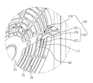
도 5는 본 발명의 일 실시예에 따른 와이어 고정부의 확대도, 도 6은 본 발명의 일 실시예에 따른 와이어 고정부의 정면도, 도 7은 도 6의 A-A'의 단면도이다.FIG. 5 is an enlarged view of a wire fixing unit according to an embodiment of the present invention, FIG. 6 is a front view of a wire fixing unit according to an embodiment of the present invention, and FIG. 7 is a sectional view taken along line A-A 'of FIG.
위에서 말한바와 같이, 송풍유닛(60)의 외측에 제어부(20)가 마련되고, 제어부(20)로부터 송풍유닛(60) 내부에 마련된 모터(68)까지 이르는 와이어(40)가 구비된다.As described above, the
그릴(70)에는 와이어(40)를 가이드 또는 고정하는 와이어 고정부(100)가 마련될 수 있다. 자세하게는 흡입그릴(72)에는 와이어(40)가 송풍팬(66)에 접하지 않도록 흡입그릴(72)을 따라 와이어(40)가 배치될 수 있도록 이를 안내하는 와이어 고정부(100)가 마련될 수 있다.The
흡입그릴(72)은 디스크플레이트(73)를 중심으로 방사상 방향인 제 1 방향(W1)으로 형성되는 제 1 그릴(75)과 원주방향인 제 2 방향(W2)으로 동심원을 가지고 복수개의 원형형상으로 구비되는 제 2 그릴(76)을 포함할 수 있으며, 와이어 고정부(100)는 제 1 방향(W1)으로 마련될 수 있다. 자세하게는 제 1 방향(W1)으로 형성된 제 1 그릴(75)에 마련되어 흡입그릴(72)에 외측에서 내측으로, 원심방향 외측에서 모터(68)가 마련되는 내측에 이르기까지 와이어(40)를 가이드 할 수 있다. 본 발명의 실시예에서는 흡입그릴(72)이 방사상 방향의 제 1 그릴(75)과 동심원을 가지는 원주방향의 제 2 그릴(76)이 마련되나, 이에 한정하지 않고 격자형상의 그릴(70)에서 가로와 세로 중 어느 하나가 제 1 그릴, 다른 하나가 제 2 그릴이 될 수 있다. 제 1 방향(W1)과 제 2 방향(W2)은 상호 방향을 달리하면 만족한다.The
와이어 고정부(100)는 가이드부(110)와, 고정플랜지(120)를 포함할 수 있다.The
가이드부(110)는 흡입그릴(72)에 와이어(40)를 안착시킬 수 있도록 와이어(40)의 일부를 가이드할 수 있다. 가이드부(110)를 통해 송풍유닛(60) 외측에서 내측으로 와이어(40)를 연결하는 경우 와이어(40)의 움직임을 제한하여, 송풍팬(66)에 와이어(40)가 접하여 단선되는 등의 문제점을 해소할 수 있다.The
가이드부(110)는 흡입그릴(72)의 디스크플레이트(73)를 중심으로 외곽에 마련되어 와이어(40)를 가이드할 수 있다.The
가이드부(110)는 제 1 방향(W1)으로 연장형성되며 와이어(40)의 상하를 가이드하는 제 1 측면 가이드부(112)와 제 2 측면 가이드부(114), 제 1 측면 가이드부(112)와 제 2 측면 가이드부(114) 중 어느 하나의 단부로부터 제 2 방향(W2)으로 연장형성되는 절곡가이드부(116)를 포함할 수 있다. 또한 와이어(40)가 와이어 고정부(100)내에서 송풍유닛(60)으로 유입되지 않도록 송풍유닛(60)측에 마련되는 내측면가이드부(118)를 더 포함할 수 있다.The
제 1 간격(G)을 가지고 이격되어 있는 제 1 측면 가이드부(112)와 제 2 측면 가이드부(114)에 의해 와이어(40)는 제 1 방향(W1)으로 안내되고, 절곡가이드부(116)에 의해 제 2 방향(W2)으로 굴곡되도록 안내할 수 있다.The
가이드부(110)의 제 1 측면 가이드부(112)와 제 2 측면 가이드부(114) 중 어느 하나는 절곡가이드부(116)와 접하게 되고, 다른 하나는 와이어(40)가 제 2 방향(W2)으로 진행할 수 있도록 가이드홀(117)이 구비된다.One of the first side
절곡가이드부(116)는 제 1 측면 가이드부(112)와 제 2 측면 가이드부(114)에 의해 제 1 방향(W1)으로 진행되는 와이어(40)를 제 2 방향(W2)으로 절곡시키도록 제 1 방향(W1)을 가로막도록 마련되는 구성이며, 본 발명의 실시예에서는 흡입그릴(72)에서 원심방향인 제 2 방향(W2)으로 마련된다. The bending
절곡가이드부(116)와 가이드홀(117)을 통해 와이어(40)는 제 1 방향(W1)에서 제 2 방향(W2)으로 절곡된 상태로 배치될 수 있고, 제 2 방향(W2)으로 유입 방향이 변경된 와이어(40)는 나선을 그리며 모터(68)에 연결될 수 있어서, 송풍팬(66) 방향으로 진행되는 것을 방지할 수 있다.The
이를 다시 설명하자면, 와이어(40)는 일정 곡률을 가지고 방향을 변경할 수 있도록 마련되는 데, 흡입그릴(72)을 중심으로 송풍유닛(60) 방향의 내측방향(I)과 타방향의 외측방향(O)으로 구분할 때, 외측방향(O)의 제어부(20)에서 내측방향(I)에 마련되는 모터(68)로 직접 연결을 하는 경우, 굴곡방향이 내측방향(I)과 외측방향(O)(O)으로만 굴곡이 되어 와이어(40)가 송풍팬(66)에 접하게 된다. 그러나 가이드부(110)를 구비하여 와이어(40)의 진행방향을 제 2 방향(W2)으로 변경하는 경우 내측방향(I)과 외측방향(O)으로 굴곡되는 성분이 감소되고, 이후 설명하는 고정플랜지(120)에 의해 외측방향(O)으로 굴곡되는 성분이 감소하게 되므로, 와이어(40)가 송풍팬(66)에 접하지 않고 모터(68)에 연결될 수 있도록 할 수 있다.The
내측면가이드부(118)는 흡입그릴(72)에 내측면에 마련되며, 자세하게는 와이어 고정부(100)에서 흡입그릴(72)의 내측면에 마련되는 구성이다,The inner
내측면가이드부(118)는 와이어 고정부(100)에 고정되는 와이어(40)가 제 1 방향(W1)과 제 2 방향(W2)으로만 배치되고, 그릴(70)의 내측 즉, 송풍유닛(60)측으로 배치되지 않도록 이를 가이드하는 구성이다.The inner
다시 말하면, 내측면가이드부(118)와 제 1 측면 가이드부(112), 제 2 측면 가이드부(114)에 의해 와이어(40)는 제 1 방향(W1)으로 배치되고, 내측면가이드부(118)와 절곡가이드부(116)에 의해 와이어(40)는 제 2 방향(W2)으로 배치될 수 있다. 이러한 구성을 통해 와이어(40)는 흡입그릴(72)에 마련된 와이어 고정부(100)에서 흡입그릴(72)의 내측으로 삽입되지 않고, 흡입그릴(72)을 따라 제 1 방향(W1)에서 제 2 방향(W2)으로 절곡 배치 될 수 있다.In other words, the
제 1 측면 가이드부(112)와 제 2 측면 가이드부(114) 중 어느하나에는 가이드부(110)의 개방된 일측을 덮을 수 있도록 마련되는 고정플랜지(120)를 마련할 수 있다.One of the first side
고정플랜지(120)는 가이드부(110)를 지나는 와이어(40)가 가이드부(110)를 이탈하지 않도록 마련되는 구성이다. The fixing
고정플랜지(120)는 제 1 연장부(122)와 제 2 연장부(124)를 포함할 수 있다.The fixed
제 1 연장부(122)는 제 1 측면 가이드부(112)와 제 2 측면 가이드부(114) 중 어느하나로부터 흡입그릴(72)의 축방향으로 연장형성되며, 제 2 연장부(124)는 제 1 연장부(122)로부터 직각이 되도록 연장형성된다. 자세하게는 제 1 연장부(122)는 흡입그릴(72)의 외측으로 연장형성된다.The
제 2 연장부(124)는 내측면가이드부(118)와 마주보도록 구성되어 와이어(40)의 측면을 가이드할 수 있도록 구성된다. 제 2 연장부(124)의 단부와 제 1 측면 가이드부(112)와 제 2 측면 가이드부(114) 중 고정플랜지(120)가 구비되지 않는 하나의 단부 사이에는 와이어(40)의 측면이 삽입될 수 있도록 제 1 거리(d) 이격되어 마련되는 삽입구(125)가 마련된다.The
삽입구(125)는 와이어(40)가 와이어 고정부(100)에 삽입될 수 있도록 와이어(40)의 직경을 고려하여 이격되는 구성이다.The
이하는 상기 구성을 갖는 공기청정기의 와이어 배치에 관하여 설명한다.Hereinafter, the wire arrangement of the air cleaner having the above-described configuration will be described.
제 2 공간(B)에 마련되는 제어부(20)와 제 1 공간(A)에 마련되는 모터(68)는 전기적으로 연결을 하기 위해 와이어(40)가 마련된다.The
와이어(40)는 제 2 공간(B)의 제어부(20)로부터 시작되어 필터프레임(32)의 와이어홀(34)을 지나게 된다. 또한 흡입그릴(72)과 필터프레임(32)사이에 보조 가이드부(152)에 의해 흡입그릴(72)로 안내될 수 있다.The
필터프레임(32)에 필터부재(30)가 안착이 되더라도 와이어홀(34)은 필터프레임(32)상에 마련되는 구성인 바, 와이어가 지날 수 있도록 마련된다.The
흡입그릴(72)에서는 와이어 고정부(100)가 마련되는 데, 와이어는 고정플랜지(120)와 가이드부(110) 사이에 삽입구(125)를 통해 삽입이 된다.In the
와이어 고정부(100)에 삽입된 와이어는 내측면가이드부(118)와 제 1 측면 가이드부(112), 제 2 측면 가이드부(114), 고정플랜지(120)에 의해 둘러쌓이며 제 1 방향(W1)으로 일부가 배치되고, 내측면가이부와 절곡가이드부(116)에 의해 제 2방향으로 절곡되도록 배치된다.The wire inserted into the
제 2 방향(W2)으로 절곡된 와이어는 제 1 측면 가이드부(112)와 제 2 측면 가이드부(114) 중 어느 하나에 마련된 가이드 홀을 통해 와이어 고정부(100)의 외부로 진행될 수 있다. 이어서 송풍유닛(60)으로 진행되어 나선형을 그리며 모터(68)의 단자부와 연결될 수 있다.The wire bent in the second direction W2 may advance to the outside of the
이러한 구성을 통해 송풍유닛(60)의 송풍팬(66)에 영향을 주지 않고, 와이어의 굴곡도를 조절하여 모터(68)와 제어부(20)를 전기적으로 연결할 수 있다.With this configuration, the
이상에서는 특정의 실시예에 대하여 도시하고 설명하였다. 그러나, 상기한 실시예에만 한정되지 않으며, 발명이 속하는 기술분야에서 통상의 지식을 가진 자라면 이하의 청구범위에 기재된 발명의 기술적 사상의 요지를 벗어남이 없이 얼마든지 다양하게 변경 실시할 수 있을 것이다. The foregoing has shown and described specific embodiments. However, it should be understood that the present invention is not limited to the above-described embodiment, and various changes and modifications may be made without departing from the technical idea of the present invention described in the following claims .
1 : 공기 청정기 10 : 캐비닛
11 : 전면패널 12 : 후면패널
12a : 흡입구 12b : 흡입가이드
13 : 측하면패널 14 : 상면패널
14a : 토출구 14b : 토출가이드
20 : 제어부 30 : 필터부재
32 : 필터프레임 34 : 와이어홀
40 : 와이어
50 : 송풍장치 60 : 송풍유닛
62 : 송풍케이스 62a : 흡입개구
62b : 토출개구 64 : 송풍유로
66 : 송풍팬 68 : 모터
70 : 그릴 72 : 흡입그릴
73 : 디스크 플레이트 74 : 모터안착부
75 : 제 1 그릴 76 : 제 2 그릴
78 : 토출그릴
100 : 와이어 고정부 110 : 가이드부
112 : 제 1 측면 가이드부 114 : 제 2 측면 가이드부
116 : 절곡가이드부 118 : 내측면가이드부
120 : 고정플랜지 122 : 제 1 연장부
124 : 제 2 연장부 125 : 삽입구
150 : 격벽 152 : 보조 가이드부
W1 : 제 1 방향 W2 : 제 2 방향
I : 내측방향 O : 외측방향
G : 제 1 간격 d : 제 1 거리
A : 제 1 공간 B : 제 2 공간1: air purifier 10: cabinet
11: Front panel 12: Rear panel
12a:
13: side surface panel 14: upper surface panel
14a:
20: control unit 30: filter member
32: filter frame 34: wire hole
40: wire
50: blower 60: blower unit
62:
62b: Discharge opening 64:
66: blower fan 68: motor
70: Grill 72: Suction Grill
73: disk plate 74: motor seat part
75: first grill 76: second grill
78: Discharge grill
100: wire fixing part 110: guide part
112: first side guide part 114: second side guide part
116: bending guide portion 118: inner side guide portion
120: Fixing flange 122: First extension
124: second extension part 125: insertion hole
150: partition wall 152: auxiliary guide portion
W1: first direction W2: second direction
I: Inner direction O: Outer direction
G: first distance d: first distance
A: first space B: second space
Claims (17)
개구가 형성된 송풍케이스와, 상기 송풍케이스 내부에 마련되는 송풍유로와, 상기 송풍유로상에 마련되는 송풍팬과, 상기 송풍케이스 내부에 마련되어 상기 송풍팬을 구동하는 모터를 갖고, 상기 캐비닛에 마련되는 송풍유닛;
상기 개구상에 형성되어 상기 송풍유닛으로 공기를 안내하는 그릴;
상기 그릴에 마련되어, 상기 송풍유닛 외부로부터 상기 모터로 전기적 신호를 전달하는 와이어가 고정되는 와이어 고정부;를 포함하는 것을 특징으로 하는 공기청정기.A cabinet forming an appearance;
A blowing fan provided in the blowing case; a motor provided inside the blowing case to drive the blowing fan; and a motor provided in the cabinet, A blowing unit;
A grill formed on the opening and guiding air to the air blowing unit;
And a wire fixing unit provided on the grill and fixing a wire for transmitting an electric signal from the outside of the blowing unit to the motor.
상기 그릴은,
그 중심으로부터 방사상방향인 제 1 방향으로 형성되는 제 1 그릴;
상기 제 1 그릴과 교차되고, 원주방향인 제 2 방향으로 동심원을 형성하며 복수의 원형으로 형성되는 제 2 그릴;을 포함하는 것을 특징으로 하는 공기청정기The method according to claim 1,
The grill may include:
A first grill formed in a first direction in a radial direction from a center thereof;
And a second grill intersecting with the first grill and formed in a plurality of circular shapes concentrically in a second direction in the circumferential direction.
상기 와이어 고정부는 와이어를 상기 그릴의 중심방향으로부터 방사상 방향인 제 1 방향에서 상기 그릴의 중심을 기준으로 원주방향인 제 2 방향으로 절곡시키도록 마련되는 것을 특징으로 하는 공기청정기.The method according to claim 1,
Wherein the wire fixing portion is provided to bend the wire in a first direction in a radial direction from a center direction of the grill and in a second direction in a circumferential direction with respect to a center of the grill.
상기 와이어 고정부는 제 1 방향으로 마련되는 것을 특징으로 하는 공기청정기.3. The method of claim 2,
Wherein the wire fixing portion is provided in a first direction.
상기 그릴은,
그 중심에 마련되는 원형의 디스크 플레이트;를 포함하고,
상기 모터는 상기 디스크 플레이트의 일면에 안착되는 것을 특징으로 하는 공기청정기.The method according to claim 1,
The grill may include:
And a circular disk plate provided at the center thereof,
Wherein the motor is seated on one surface of the disc plate.
상기 와이어 고정부는,
상기 그릴상에서 와이어를 가이드하는 가이드부;
상기 가이드부로부터 연장형성되어 상기 가이드부에 안착된 와이어의 이탈을 방지하는 고정플랜지;를 포함하는 것을 특징으로 하는 공기청정기.The method of claim 3,
The wire-
A guide portion for guiding the wire on the grill;
And a fixing flange extending from the guide portion to prevent the wire from being separated from the guide portion.
상기 가이드부는,
와이어의 양측을 상기 제 1 방향으로 가이드하도록 상기 제 1 방향으로 형성되는 제 1 측면 가이드부와 제 2 측면 가이드부;
상기 제 1 측면 가이드부와 상기 제 2 측면 가이드부 중 어느 하나와 접하며, 와이어를 상기 제 2 방향으로 굴곡시키도록 상기 제 2 방향으로 형성되는 절곡가이드부;를 포함하는 것을 특징으로 하는 공기청정기.The method according to claim 6,
The guide portion
A first side surface guide portion and a second side surface guide portion formed in the first direction to guide both sides of the wire in the first direction;
And a bending guide portion which is in contact with any one of the first side surface guide portion and the second side surface guide portion and is formed in the second direction so as to bend the wire in the second direction.
상기 제 1 측면 가이드부와 상기 제 2 측면 가이드부 중 상기 절곡가이드부와 접하지 않는 다른 하나는 상기 절곡가이드부에 의해 상기 제 2 방향으로 굴곡된 와이어가 지날 수 있도록 마련되는 가이드홀;을 포함하는 것을 특징으로 하는 공기청정기.8. The method of claim 7,
And the other one of the first side surface guide portion and the second side surface guide portion which is not in contact with the bending guide portion is a guide hole provided so that the wire bent in the second direction can be guided by the bending guide portion Wherein the air cleaner comprises:
상기 고정 플랜지는,
상기 가이드부로부터 상기 그릴의 축방향으로 연장형성되는 제 1 연장부;
상기 제 1 연장부에 직각으로 연장형성되는 제 2 연장부;를 포함하는 것을 특징으로 하는 공기청정기.The method according to claim 6,
The fixing flange
A first extending portion extending from the guide portion in the axial direction of the grill;
And a second extension portion extending perpendicularly to the first extension portion.
상기 캐비닛을 제 1 공간과 제 2 공간으로 구획하는 격벽;
상기 격벽상에 마련되며, 상기 제 2 공간에서 제 1 공간으로 내부 공기를 안내하는 그릴;
상기 그릴로부터 유입되는 내부 공기를 상기 토출구로 송풍하는 송풍팬과, 상기 송풍팬을 구동하는 모터를 갖고, 제 1 공간에 마련되는 송풍유닛;
상기 모터를 제어하고, 제 2 공간에 마련되는 제어부;를 포함하고,
상기 그릴은,
상기 제어부로부터 상기 모터로 전기적 신호를 전달하는 와이어를 가이드하는 와이어 고정부;를 포함하는 것을 특징으로 하는 공기청정기.A cabinet having a suction port and a discharge port;
A partition wall partitioning the cabinet into a first space and a second space;
A grill provided on the partition wall for guiding the internal air from the second space to the first space;
A blowing fan for blowing the air introduced from the grill to the discharge port, and a motor for driving the blowing fan, the blowing unit being provided in the first space;
And a control unit controlling the motor and provided in a second space,
The grill may include:
And a wire fixing part for guiding a wire for transmitting an electric signal from the control part to the motor.
와이어는 상기 그릴의 중심으로부터 방사상?항인 제 1 방향으로 상기 그릴의 외주부부터 정렬되고, 상기 와이어 고정부에 의해 상기 그릴의 원주방향인 제 2 방향으로 절곡되도록 마련되는 것을 특징으로 하는 공기청정기.11. The method of claim 10,
Wherein the wire is arranged from an outer peripheral portion of the grill in a first direction which is a radial direction from a center of the grill and bent in a second direction which is a circumferential direction of the grill by the wire fixing portion.
상기 와이어 고정부는,
와이어가 상기 그릴의 중심을 기준으로 방사상 방향인 제 1 방향에서 원주방향인 제 2 방향으로 절곡되어 배치될 수 있도록 절곡가이드부;를 포함하는 것을 특징으로 하는 공기청정기.11. The method of claim 10,
The wire-
And a bending guide portion that allows the wire to be bent and arranged in a second direction in a circumferential direction in a first direction which is radial direction with respect to a center of the grill.
상기 와이어 고정부는,
상기 제 1 방향으로 진행되는 와이어의 측면을 가이드 하는 가이드부;를 더 포함하는 것을 특징으로 하는 공기청정기.13. The method of claim 12,
The wire-
And a guiding part for guiding a side surface of the wire traveling in the first direction.
상기 가이드부는,
상호 평행하도록 마련되고 그 사이에 와이어를 가이드하는 제 1 측면가이드부와 제 2 측면가이드부;를 포함하고,
상기 제 1 측면가이드부와 상기 제 2 측면가이드부 중 어느 하나는 상기 절곡가이드부와 접하며,
다른 하나는 상기 절곡가이드부와의 사이에 상기 제 1 방향에서 상기 제 2 방향으로 절곡된 와이어가 지날 수 있도록 마련되는 가이드홀;을 포함하는 것을 특징으로 하는 공기청정기.14. The method of claim 13,
The guide portion
And a first side surface guide portion and a second side surface guide portion which are provided so as to be parallel to each other and guide the wire therebetween,
Wherein one of the first side surface guide portion and the second side surface guide portion contacts the bending guide portion,
And a guide hole provided between the guide portion and the bent guide portion so that a wire bent in the second direction from the first direction can pass through the guide hole.
상기 와이어 고정부는,
상기 그릴에 고정된 와이어의 이탈을 방지하도록 상기 가이드부로부터 돌출형성된 고정플랜지;를 더 포함하는 것을 특징으로 하는 공기청정기.14. The method of claim 13,
The wire-
Further comprising: a fixing flange protruding from the guide portion to prevent the wire from being detached from the grill.
상기 고정 플랜지는,
상기 가이드부로부터 상기 그릴의 축방향으로 연장형성되는 제 1 연장부;
상기 제 1 연장부에 직각으로 연장형성되는 제 2 연장부;를 포함하는 것을 특징으로 하는 공기청정기.16. The method of claim 15,
The fixing flange
A first extending portion extending from the guide portion in the axial direction of the grill;
And a second extension portion extending perpendicularly to the first extension portion.
상기 흡입구와 연통하는 흡입개구와, 상기 토출구와 연통하는 토출개구와, 상기 흡입개구와 상기 토출개구 사이에 마련되는 송풍팬과, 상기 송풍팬을 구동하는 모터와, 상기 흡입개구상에 마련되며 일측에 상기 모터가 안착되는 그릴을 갖고, 상기 캐비닛 내부에 마련되는 송풍유닛;
상기 송풍유닛의 외부에 마련되는 제어부;
상기 제어부로부터 상기 모터로 전기적 신호를 전달하는 와이어를 가이드하도록 상기 그릴에 마련되는 와이어 고정부;를 포함하는 것을 특징으로 하는 공기청정기.A cabinet having a suction port and a discharge port;
A suction opening communicating with the suction port, a discharge opening communicating with the discharge port, a blowing fan provided between the suction opening and the discharge opening, a motor for driving the blowing fan, An air blowing unit provided in the cabinet and having a grill on which the motor is mounted;
A control unit provided outside the blowing unit;
And a wire fixing part provided on the grill so as to guide a wire for transmitting an electric signal from the control part to the motor.
Priority Applications (2)
| Application Number | Priority Date | Filing Date | Title |
|---|---|---|---|
| KR1020130061912A KR20140141775A (en) | 2013-05-30 | 2013-05-30 | Air Cleaner |
| US14/187,973 US20140357180A1 (en) | 2013-05-30 | 2014-02-24 | Air cleaner |
Applications Claiming Priority (1)
| Application Number | Priority Date | Filing Date | Title |
|---|---|---|---|
| KR1020130061912A KR20140141775A (en) | 2013-05-30 | 2013-05-30 | Air Cleaner |
Publications (1)
| Publication Number | Publication Date |
|---|---|
| KR20140141775A true KR20140141775A (en) | 2014-12-11 |
Family
ID=51985640
Family Applications (1)
| Application Number | Title | Priority Date | Filing Date |
|---|---|---|---|
| KR1020130061912A KR20140141775A (en) | 2013-05-30 | 2013-05-30 | Air Cleaner |
Country Status (2)
| Country | Link |
|---|---|
| US (1) | US20140357180A1 (en) |
| KR (1) | KR20140141775A (en) |
Cited By (1)
| Publication number | Priority date | Publication date | Assignee | Title |
|---|---|---|---|---|
| US20150352479A1 (en) * | 2014-06-09 | 2015-12-10 | Samsung Electronics Co., Ltd. | Air cleaner |
Families Citing this family (4)
| Publication number | Priority date | Publication date | Assignee | Title |
|---|---|---|---|---|
| KR101717344B1 (en) | 2015-03-16 | 2017-03-27 | 엘지전자 주식회사 | Outdoor unit of air conditioner |
| CN109028383B (en) * | 2018-07-17 | 2021-08-13 | 广东美的制冷设备有限公司 | High-pressure bag subassembly and air treatment device |
| CN109028379B (en) * | 2018-07-17 | 2021-11-23 | 广东美的制冷设备有限公司 | Air treatment device |
| USD1021039S1 (en) * | 2021-11-15 | 2024-04-02 | Inter Ikea Systems B.V. | Air purifier |
Family Cites Families (3)
| Publication number | Priority date | Publication date | Assignee | Title |
|---|---|---|---|---|
| US4392525A (en) * | 1980-11-03 | 1983-07-12 | Carrier Corporation | Apparatus for securing a wire to a grille |
| US6610118B2 (en) * | 1999-07-07 | 2003-08-26 | The Holmes Group, Inc. | Air purifier |
| FR2961490B1 (en) * | 2010-06-22 | 2013-07-26 | Airbus Operations Sas | FIXING ASSEMBLY COMPRISING RAMPS FOR FASTENING SYSTEMS IN AN AIRCRAFT. |
-
2013
- 2013-05-30 KR KR1020130061912A patent/KR20140141775A/en not_active Application Discontinuation
-
2014
- 2014-02-24 US US14/187,973 patent/US20140357180A1/en not_active Abandoned
Cited By (2)
| Publication number | Priority date | Publication date | Assignee | Title |
|---|---|---|---|---|
| US20150352479A1 (en) * | 2014-06-09 | 2015-12-10 | Samsung Electronics Co., Ltd. | Air cleaner |
| US9873127B2 (en) * | 2014-06-09 | 2018-01-23 | Samsung Electronics Co., Ltd. | Air cleaner |
Also Published As
| Publication number | Publication date |
|---|---|
| US20140357180A1 (en) | 2014-12-04 |
Similar Documents
| Publication | Publication Date | Title |
|---|---|---|
| JP6655186B2 (en) | Air cleaner | |
| KR102231096B1 (en) | Air cleaner | |
| US9914082B2 (en) | Air cleaner | |
| KR102095989B1 (en) | Upright air conditioner with swing louvers | |
| KR20140141775A (en) | Air Cleaner | |
| KR102502550B1 (en) | Air blower and air cleaner having the same | |
| ES2602132T3 (en) | Indoor unit of an air conditioner | |
| KR101837621B1 (en) | Air conditioner | |
| JP2019509171A (en) | Air cleaner | |
| JP2008142665A (en) | Air cleaner | |
| KR101500506B1 (en) | Air conditioner | |
| KR102396592B1 (en) | Rapid cycling air conditioner | |
| KR101856986B1 (en) | Air conditioner | |
| US20210123611A1 (en) | Diffuser, diffuser assembly, and air conditioner having the same | |
| JP6653441B2 (en) | Ceiling embedded indoor unit | |
| KR20170077660A (en) | Air conditioner | |
| KR101529223B1 (en) | Air conditioner and Control method of the same | |
| JP2005055063A (en) | Outdoor machine for air conditioner | |
| JP5692209B2 (en) | Air conditioner | |
| JP2002235930A (en) | Air conditioner | |
| CN114761693A (en) | Centrifugal blower | |
| KR20220042907A (en) | Air purifier for vehicle | |
| KR102268850B1 (en) | 360 degree ratation type air cleaner | |
| JP2016142475A (en) | Air cleaner | |
| CN112833476B (en) | Air conditioner |
Legal Events
| Date | Code | Title | Description |
|---|---|---|---|
| WITN | Application deemed withdrawn, e.g. because no request for examination was filed or no examination fee was paid |