EP3385437A1 - Front-loading washing machine - Google Patents
Front-loading washing machine Download PDFInfo
- Publication number
- EP3385437A1 EP3385437A1 EP16869953.6A EP16869953A EP3385437A1 EP 3385437 A1 EP3385437 A1 EP 3385437A1 EP 16869953 A EP16869953 A EP 16869953A EP 3385437 A1 EP3385437 A1 EP 3385437A1
- Authority
- EP
- European Patent Office
- Prior art keywords
- clutch
- drum
- rotating
- clutch body
- engaged
- Prior art date
- Legal status (The legal status is an assumption and is not a legal conclusion. Google has not performed a legal analysis and makes no representation as to the accuracy of the status listed.)
- Withdrawn
Links
Images









Classifications
-
- D—TEXTILES; PAPER
- D06—TREATMENT OF TEXTILES OR THE LIKE; LAUNDERING; FLEXIBLE MATERIALS NOT OTHERWISE PROVIDED FOR
- D06F—LAUNDERING, DRYING, IRONING, PRESSING OR FOLDING TEXTILE ARTICLES
- D06F37/00—Details specific to washing machines covered by groups D06F21/00 - D06F25/00
- D06F37/30—Driving arrangements
- D06F37/304—Arrangements or adaptations of electric motors
-
- D—TEXTILES; PAPER
- D06—TREATMENT OF TEXTILES OR THE LIKE; LAUNDERING; FLEXIBLE MATERIALS NOT OTHERWISE PROVIDED FOR
- D06F—LAUNDERING, DRYING, IRONING, PRESSING OR FOLDING TEXTILE ARTICLES
- D06F23/00—Washing machines with receptacles, e.g. perforated, having a rotary movement, e.g. oscillatory movement, the receptacle serving both for washing and for centrifugally separating water from the laundry
- D06F23/06—Washing machines with receptacles, e.g. perforated, having a rotary movement, e.g. oscillatory movement, the receptacle serving both for washing and for centrifugally separating water from the laundry and rotating or oscillating about an inclined axis
-
- D—TEXTILES; PAPER
- D06—TREATMENT OF TEXTILES OR THE LIKE; LAUNDERING; FLEXIBLE MATERIALS NOT OTHERWISE PROVIDED FOR
- D06F—LAUNDERING, DRYING, IRONING, PRESSING OR FOLDING TEXTILE ARTICLES
- D06F37/00—Details specific to washing machines covered by groups D06F21/00 - D06F25/00
- D06F37/02—Rotary receptacles, e.g. drums
- D06F37/04—Rotary receptacles, e.g. drums adapted for rotation or oscillation about a horizontal or inclined axis
- D06F37/06—Ribs, lifters, or rubbing means forming part of the receptacle
-
- D—TEXTILES; PAPER
- D06—TREATMENT OF TEXTILES OR THE LIKE; LAUNDERING; FLEXIBLE MATERIALS NOT OTHERWISE PROVIDED FOR
- D06F—LAUNDERING, DRYING, IRONING, PRESSING OR FOLDING TEXTILE ARTICLES
- D06F37/00—Details specific to washing machines covered by groups D06F21/00 - D06F25/00
- D06F37/30—Driving arrangements
- D06F37/40—Driving arrangements for driving the receptacle and an agitator or impeller, e.g. alternatively
-
- D—TEXTILES; PAPER
- D06—TREATMENT OF TEXTILES OR THE LIKE; LAUNDERING; FLEXIBLE MATERIALS NOT OTHERWISE PROVIDED FOR
- D06F—LAUNDERING, DRYING, IRONING, PRESSING OR FOLDING TEXTILE ARTICLES
- D06F17/00—Washing machines having receptacles, stationary for washing purposes, wherein the washing action is effected solely by circulation or agitation of the washing liquid
- D06F17/06—Washing machines having receptacles, stationary for washing purposes, wherein the washing action is effected solely by circulation or agitation of the washing liquid by rotary impellers
- D06F17/08—Driving arrangements for the impeller
Definitions
- the present disclosure relates to a drum washing machine, which not only can be continuously operated from washing to drying, but also can carry out washing without drying.
- a transverse-shaft type drum is rotated in an outer drum which stores water at a bottom, washings are lifted up and dropped down by baffles arranged in the drum, and the washings are thrown to an inner circumferential surface of the drum to realize washing.
- baffles arranged in the drum, and the washings are thrown to an inner circumferential surface of the drum to realize washing.
- the following structure can be adopted: a stirring body is arranged on a rear surface of the drum, so that the drum and the stirring body can independently rotate at different rotating speeds during washing and rinsing (see a patent literature 1).
- a clutch mechanism part for switching a driving mode between a first mode in which the drum and the stirring body independently rotate and a second mode in which the drum and the stirring body integrally rotate is arranged.
- the drum and the stirring body are rotationally driven by a driving motor.
- a rotating shaft of the drum is connected with a planetary carrier of a planetary gear mechanism, and the rotation of the driving motor is transferred to the drum by virtue of the planetary gear mechanism.
- the clutch mechanism part includes a clutch body and a moving mechanism part.
- the clutch body is connected with an internal gear that forms the planetary gear mechanism in a manner that the clutch body cannot rotate relative to the internal gear.
- the moving mechanism part enables the clutch body to move between a driving motor side and a bearing unit side of the rotating shaft supporting the drum freely and rotationally.
- Splines are formed on the clutch body, at the rotor side end and at the bearing unit side end along a circumferential direction, and splines corresponding to the spline on the clutch body are formed on the rotor and the bearing unit.
- the splines of the clutch body are engaged with the splines of the bearing unit in the first mode.
- the internal gear is fixed to the bearing unit by virtue of the clutch body in a manner that the internal gear cannot circumferentially rotate.
- the drum rotates independently of the stirring body at a rotating speed lower than that of the stirring body according to a reduction ratio of the planetary gear mechanism.
- the splines of the clutch body are engaged with the splines of the rotor in the second mode.
- the internal gear is fixed to the rotor by virtue of the clutch body.
- the drum integrally rotates with the stirring body at a rotating speed equal to that of the stirring body when the rotor rotates in this state.
- the following condition may occur in the above drum washing machine: when the clutch body moves to the bearing unit side through the moving mechanism part, teeth of the splines of the clutch body and teeth of the splines of the bearing unit are abutted with each other rather than engaged.
- the clutch body is continuously pushed to the bearing unit side by the moving mechanism part.
- the clutch body rotates through the internal gear along with the rotation of the rotor and a position of the tooth of the spline of the clutch body is shifted to a position not affected by the tooth of the spline of the bearing unit, the clutch body suddenly moves to the bearing unit side, so that the teeth of the splines are mutually engaged.
- impact sound which is harsh for a user may be generated between the clutch body and the bearing unit.
- teeth of the splines may also be abutted with each other rather than engaged.
- the clutch body is continuously pushed to the rotor side by the moving mechanism part.
- the clutch body suddenly moves to the rotor side, so that the teeth of the splines are mutually engaged.
- impact sound which is harsh for a user may be generated between the clutch body and the rotor.
- Patent Literature 1 Japanese Laid-Open Patent Publication No. 2015-167663
- a purpose of the present disclosure is as follows: for a drum washing machine with a rotating body on a rear part of a drum, sound generated when a driving mode is switched between a first mode in which the drum and the rotating body independently rotate and a second mode in which the drum and the rotating body integrally rotate.
- a drum washing machine includes: an outer drum arranged in a housing; a drum arranged in the outer drum and rotatable about a horizontal axis or an inclined axis inclined with respect to a horizontal direction; a rotating body arranged in a rear part of the drum, wherein a surface of the rotating body is provided with a baffle for contacting laundry; and a driving part configured to rotate the drum and the rotating body.
- the driving part includes: a driving motor; a first rotating shaft configured to transmit rotation of the driving motor to the rotating body; a second rotating shaft coaxially arranged with the first rotating shaft and configured to transmit the rotation of the driving motor to the drum; a planetary gear mechanism, including a sun gear rotating along with the rotation of the driving motor, an annular internal gear surrounding the sun gear, a plurality of planetary gears interposed between the sun gear and the internal gear, and a planetary carrier free rotatably holding the plurality of planetary gears, where one of the planetary carrier and the internal gear is fixed to the second rotating shaft; and a clutch mechanism part, configured to switch a driving mode of the driving part between a first mode and a second mode.
- the first mode is a driving mode in which the first rotating shaft and the second rotating shaft independently rotate
- the second mode is a driving mode in which the first rotating shaft and the second rotating shaft integrally rotate.
- the clutch mechanism part includes: a clutch body, connected to the other one of the planetary carrier and the internal gear in such a state that the clutch body is rotatable together with the other one of the planetary carrier and the internal gear and is moveable towards an axis direction of the second rotating shaft; a moving mechanism part, configured to enable the clutch body to move to a first position when switching to the first mode, and enable the clutch body to move to a second position when switching to the second mode; a first engaging part with a concave-convex shape and a second engaging part with a concave-convex shape formed in the clutch body; a first engaged part formed in a fixing part which does not rotate along with the driving motor, wherein the first engaged part has a concave-convex shape corresponding to the concave-convex shape of the first
- the other party connected with the clutch body such as the planetary carrier
- the driving mode is switched to the first mode.
- one party such as the second rotating shaft connected with internal gear
- the drum and the rotating body independently rotate at different rotating speeds.
- the other party connected with the clutch body rotates along with the driving motor, and the driving mode is switched to the second mode.
- the driving motor rotates
- the second rotating shaft rotates at a rotating speed equal to the rotating speed of the first rotating shaft.
- the drum and the rotating body integrally rotate at the same rotating speed.
- the fixing part-side cushioning member provided on the clutch body side or the fixing part side firstly touches the object side when the first engaging part and the first engaged part are engaged, such that the impact force generated between the clutch body and the fixing part is reduced. Therefore, impact sound generated between the clutch body side and the fixing part side can be reduced.
- the driving part can also include a bearing part that free rotatably supports the second rotating shaft.
- the fixing part is mounted on the bearing part.
- the fixing part-side cushioning member is mounted on the fixing part side, and has a flange part sandwiched by the fixing part and the bearing part.
- the fixing part-side cushioning member is fixed to the fixing part side through the flange part which is clamped by the bearing part and the fixing part. Therefore, the fixing part-side cushioning member is easily fixed to the fixing part side.
- a rotating part-side cushioning member may be arranged on either the clutch body side or the rotating part side.
- the rotating part-side cushioning member firstly touches the object side when the second engaging part and the second engaged part are engaged, so as to reduce an impact force generated between the clutch body and the rotating part.
- the rotating part-side cushioning member arranged on the clutch body side or the rotating part side firstly touches the object side when the second engaging part and the second engaged part are engaged, and the impact force generated between the clutch body and the rotating part is weakened. Therefore, the impact sound generated between the clutch body side and the rotating part side can be reduced.
- a drum washing machine in a second mode of the present disclosure includes: an outer drum arranged in a housing; a drum arranged in the outer drum and is rotatable about a horizontal axis or an inclined axis inclined with respect to a horizontal direction; a rotating body arranged in a rear part of the drum, wherein a surface of the rotating body is provided with a baffle for contacting laundry; and a driving part configured to rotate the drum and the rotating body.
- the driving part includes: a driving motor; a first rotating shaft configured to transmit rotation of the driving motor to the rotating body; a second rotating shaft coaxially arranged with the first rotating shaft and configured to transmit the rotation of the driving motor to the drum; a planetary gear mechanism, including a sun gear rotating along with the rotation of the driving motor, an annular internal gear surrounding the sun gear, a plurality of planetary gears interposed between the sun gear and the internal gear, and a planetary carrier free rotatably holding the plurality of planetary gears, where one of the planetary carrier and the internal gear is fixed to the second rotating shaft; and a clutch mechanism part, configured to switch a driving mode of the driving part between a first mode and a second mode.
- the first mode is a driving mode in which the first rotating shaft and the second rotating shaft independently rotate
- the second mode is a driving mode in which the first rotating shaft and the second rotating shaft integrally rotate.
- the clutch mechanism part includes: a clutch body, connected to the other one of the planetary carrier and the internal gear in such a state that the clutch body is rotatable together with the other one of the planetary carrier and the internal gear and is moveable towards an axis direction of the second rotating shaft; a moving mechanism part, configured to enable the clutch body to move to a first position when switching to the first mode, and enable the clutch body to move to a second position when switching to the second mode; a first engaging part with a concave-convex shape and a second engaging part with a concave-convex shape which are formed in the clutch body; a first engaged part which is formed in a fixing part that does not rotate along with the driving motor, wherein the first engaged part has a concave-convex shape corresponding to the concave-convex
- the impact sound generated between the clutch body side and the rotating part side can also be reduced like the drum washing machine in the first mode.
- the drum washing machine in the first mode or the second mode can adopt the following structure: the rotating part-side cushioning member is arranged on the clutch body side and has a claw part, and the clutch body has a hole part for inserting and locking the claw part.
- the rotating part-side cushioning member is fixed to the clutch body side by locking the claw part of the rotating part-side cushioning member to the hole part of the clutch body. Therefore, the rotating part-side cushioning member can be easily fixed to the clutch body side.
- the sound generated when the driving mode is switched between the first mode in which the drum and the rotating body independently rotate and the second mode in which the drum and the rotating body integrally rotate.
- FIG. 1 is a side sectional view illustrating a structure of a drum washing machine 1.
- the drum washing machine 1 includes a housing 10 forming an appearance.
- a front surface 10a of the housing 10 is inclined from a central part to an upper part, and a laundry inlet 11 is formed in the inclined surface.
- the laundry inlet 11 is covered by a door 12 which is freely opened and closed.
- an outer drum 20 is elastically supported by a plurality of vibration dampers 21.
- a drum 22 is provided in the outer drum 20 in a free rotation manner.
- the outer drum 20 and the drum 22 are inclined in such a manner that rear surface sides thereof are lowered relative to a horizontal direction.
- the drum 22 rotates about an inclination axis inclined relative to the horizontal direction.
- Inclination angles of the outer drum 20 and the drum 22 may be set as about 10 degrees-20 degrees.
- An opening part 20a on the front surface of the outer drum 20 and an opening part 22a on the front surface of the drum 22 are opposed to the laundry inlet 11, and are opened and closed by the door 12, together with the laundry inlet 11.
- a plurality of dewatering holes 22b are formed in an inner circumferential surface of the drum 22.
- three baffles 23 are arranged in the circumferential direction at substantially equal intervals on the inner circumferential surface of the drum 22.
- a stirring body 24 is freely-rotatably disposed at the rear of the drum 22.
- the stirring body 24 has a substantially disc shape.
- a plurality of blades 24a that radially extend from the central part are formed on the surface of the stirring body 24.
- the stirring body 24 coaxially rotates with the drum 22.
- the stirring body 24 is equivalent to a rotating body in the present disclosure, and the blades 24a are equivalent to the baffles in the present disclosure.
- a driving unit 30 capable of generating a torque for driving the drum 22 and the stirring body 24 is disposed behind the outer drum 20.
- the driving unit 30 is equivalent to a driving part in the present disclosure.
- the driving unit 30 enables the drum 22 and the stirring body 24 to rotate at different rotating speeds in the same direction in a washing process and a rinsing process.
- the driving unit 30 enables the drum 22 to rotate at a rotating speed through which the centrifugal force applied to the laundry in the drum 22 is smaller than gravity, and enables the stirring body 24 to rotate at a rotating speed higher than the rotating speed of the drum 22.
- the driving unit 30 enables the drum 22 and the stirring body 24 to integrally rotate at a rotating speed through which the centrifugal force applied to the laundry in the drum 22 is much larger than the gravity in a dewatering process.
- a detailed structure of the driving unit 30 is described below.
- a water outlet part 20b is formed in the bottom of the outer drum 20.
- a drainage valve 40 is provided in the water outlet part 20b.
- the drainage valve 40 is connected with a drainage hose 41. When the drainage valve 40 is opened, water stored in the outer drum 20 is discharged out of the machine by the drainage hose 41.
- a detergent box 50 is provided on the front upper part of the housing 10.
- a detergent container 50a containing detergents is contained in the detergent box 50 in a free withdrawal manner.
- the detergent box 50 is connected with a water supply valve 51 provided on the upper rear part of the housing 10 via a soft water hose 52.
- the detergent box 50 is connected with the upper part of the outer drum 20 through a water filing pipe 53.
- FIG. 2 and FIG. 3 are sectional views illustrating a structure of a driving unit 30.
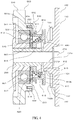
- FIG. 4 and FIG. 5 are sectional views illustrating an essential part enlarging a periphery of a clutch body 610.
- FIG. 2 and FIG. 4 show the driving unit 30 when a driving mode of the driving unit 30 is switched to a biaxial driving mode.
- FIG. 3 and FIG. 5 show the driving unit 30 when a driving mode of the driving unit 30 is switched to a uniaxial driving mode.
- FIG. 6 is front view illustrating a rotor 110 of a driving motor 100.
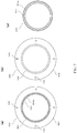
- FIG. 7(a) and FIG. 7(b) are a front view and a rear view illustrating a clutch carrying plate 530 respectively, and FIG.
- FIG. 7(c) is a front view illustrating a bearing-side cushioning member 540.
- FIG. 8(a) to FIG. 8(c) are a front view, a side longitudinal sectional view and a rear view illustrating a clutch body 610 respectively, and
- FIG. 8(d) is a sectional view illustrating a planetary carrier shaft 441. It should be noted that a clutch lever 630 is not shown in FIG. 4 and FIG. 5 .
- the driving unit 30 includes: a driving motor 100, a wing shaft 200, a drum shaft 300, a planetary gear mechanism 400, a bearing unit 500 and a clutch mechanism part 600.
- the driving motor 100 generates a torque for driving the stirring body 24 and the drum 22.
- the wing shaft 200 rotates through the torque of the driving motor 100, and transfers the rotation to the stirring body 24.
- the planetary gear mechanism 400 decelerates the rotation of the wing shaft 200 (i.e., the rotation of the rotor 110 of the driving motor 100) and transfers the rotation to the drum shaft 300.
- the drum shaft 300 rotates coaxially with the wing shaft 200 at the rotating speed reduced by the planetary gear mechanism 400, and transfers the rotation to the drum 22.
- the bearing unit 500 supports the wing shaft 200 and the drum shaft 300 in a free rotation manner.
- the clutch mechanism part 600 switches the driving mode of the driving unit 30 between the biaxial driving mode and the uniaxial driving mode.
- the biaxial driving mode is a driving mode that enables the stirring body 24 (i.e., the wing shaft 200) to rotate at a rotating speed equal to the rotating speed of the driving motor 100 and enables the drum 22 (i.e., the drum shaft 300) to rotate at a rotating speed reduced by the planetary gear mechanism 400.
- the uniaxial driving mode is a driving mode that enables the stirring body 24 and the drum 22 (i.e., the wing shaft 200), as well as the drum shaft 300 and the planetary gear mechanism 400 to integrally rotate at a rotating speed equal to the rotating speed of the driving motor 100.
- the wing shaft 200 corresponds to a first rotating shaft in the present disclosure
- the drum shaft 300 corresponds to a second rotating shaft in the present disclosure.
- the biaxial driving mode corresponds to a first mode in the present disclosure
- the uniaxial driving mode corresponds to a second mode in the present disclosure.
- the driving motor 100 is an outer rotor type DC brushless motor and includes a rotor 110 and a stator 120.
- the rotor 110 is formed in a bottomed cylinder shape and made from reinforced resin which is formed by mixing reinforcing materials such as glass in resin, and permanent magnets 111 are arranged throughout the entire circumference on the inner circumferential surface of the rotor 110.
- a clutch carrying part 130 is integrally formed with the rotor 110 on a central part of the rotor 110. The clutch carrying part 130 and the driving motor 100 (i.e., the rotor 110) are rotated together.
- the clutch carrying part 130 includes a lug boss part 131, an engaged part 132 and a touch surface 133.
- the lug boss part 131 has a substantially trapezoidal cross section and a lug boss hole 131a in the central part.
- the wing shaft 200 extends through the lug boss hole 131a.
- the lug boss hole 131a is communicated with a recess 112 formed in a central of a rear surface of the rotor 110.
- the engaged part 132 is formed at a periphery of the lug boss part 131, and has a substantially annular shape.
- a plurality of engaging recesses 132b recessed towards a side deeper than the surface 132a of the engaged part 132 are formed along the circumferential direction at substantially equal intervals on the engaged part 132. In this way, a concave-convex shape is formed along the circumferential direction on the engaged part 132 through the surface 132a and the engaging recesses 132b.
- the touch surface 133 is arranged between the lug boss part 131 and the engaged part 132, and has a flat surface protruded by a section from the surface 132a of the engaged part 132.
- the clutch carrying part 130 corresponds to a rotating part in the present disclosure
- the engaged part 132 corresponds to a second engaged part in the present disclosure.
- a coil 121 is arranged on an outer circumferential part of the stator 120.
- a driving current is supplied to the coil 121 of the stator 120 from an after-mentioned motor driving part, the rotor 110 rotates.
- the drum shaft 300 is of a hollow shape and encloses the wing shaft 200 and the planetary gear mechanism 400.
- the central part of the drum shaft 300 is bulged outwards.
- the bulged part forms a containing part of the planetary gear mechanism 400.
- the planetary gear mechanism 400 includes: a sun gear 410, an annular internal gear 420 surrounding the sun gear 410, a plurality of groups of planetary gears 430 between the sun gear 410 and the internal gear 420, and a planetary carrier 440 holding the planetary gears 430 in a free rotation manner.
- the sun gear 410 is fixed to the wing shaft 200, and is rotated with the rotation of the driving motor 100.
- the internal gear 420 is fixed to the drum shaft 300.
- a group of planetary gears 430 includes a first gear and a second gear which are engaged mutually and rotated in opposed directions.
- the planetary carrier 440 includes a planetary carrier shaft 441 extending backwards.
- the planetary carrier shaft 441 is coaxial with the drum shaft 300, and is internally hollowed to insert the wing shaft 200.
- a rear end part of the wing shaft 200 is protruded backwards from the planetary carrier shaft 441, and is fixed to the lug boss hole 131a of the rotor 110 through an installing bolt 210.
- a head of the installing bolt 210 is accommodated in the recess 112 of the rotor 110, and is not further protruded backwards than the rotor 110.
- a cylindrical bearing part 510 is arranged on the central part of the bearing unit 500.
- rolling bears 511 and 512 are arranged on the front portion and on the rear portion respectively.
- a mechanical seal 513 is arranged on the front end part.
- An outer circumferential surface of the drum shaft 300 is carried by the rolling bears 511 and 512, and rotates smoothly in the bearing part 510.
- the mechanical seal 513 is used to prevent water from entering a place between the bearing part 510 and the drum shaft 300.
- a fixing flange part 520 is formed around the bearing part 510 of the bearing unit 500.
- An installing lug boss 521 is formed on a lower end part of the fixing flange part 520.
- a clutch carrying plate 530 is installed on a rear end part of the bearing part 510.
- the clutch carrying plate 530 is made of reinforced resin that is same as the reinforced resin of the rotor 110, and includes a carrying body part 531, a flange part 532 and a pressing part 533.
- the carrying body part 531 is formed in a flat cylindrical shape, and has a spline 534 on an inner side surface. Each tooth 534a of the spline 534 is formed along the circumferential direction of the carrying body part 531 at substantially equal intervals, and is protruded to an inner side of the carrying body part 531.
- the flange part 532 is formed on an outer circumferential surface of the carrying body part 531 and has a circular shape. Inserting through holes 535 through which screws 550 go are formed in multiple positions of the flange part 532.
- the pressing part 533 is protruded from the carrying body part 531 to the rolling bearing 512, and has a circular shape.
- the clutch carrying plate 530 corresponds to a fixing part in the present disclosure
- the spline 534 corresponds to the first engaged part in the present disclosure.
- the clutch carrying plate 530 is fixed to a rear end part of the bearing part 510 through the screw 550.
- the screw 550 goes through the inserting through hole 535 and is fastened to a screw hole 514 formed at the rear end part of the bearing part 510.
- a bearing-side cushioning member 540 is provided at an inner circumferential side of the carrying body part 531 of the clutch carrying plate 530. As shown in FIG. 4 , FIG. 5 and FIG. 7(c) , the bearing-side cushioning member 540 has a flat cylindrical shape, and is made of rubber or other elastic materials. The bearing-side cushioning member 540 corresponds to the fixed part side cushioning member in the present disclosure.
- the bearing-side cushioning member 540 has a circular flange part 541. The flange part 541 is sandwiched between the rolling bearing 512 of the bearing part 510 and the pressing part 533 of the clutch carrying plate 530, and is pressed to the rolling bearing 512 side by the pressing part 533.
- the bearing-side cushioning member 540 is fixed to the clutch carrying plate 530 side.
- the outer circumferential edge of the flange part 541 is provided with an annular protruding part 541a, and the protruding part 541a comes into contact with the outer circumferential surface of the pressing part 533 so that the flange part 541 is less likely to come off a part between the rolling bearing 512 and the pressing part 533.
- a spring carrying part 560 is arranged behind the rolling bearing 512 and at the inner side of the bearing-side cushioning member 540.
- the bearing unit 500 is fixed to a rear surface of the outer drum 20 via the fixing flange part 520 through fixing methods such as screw fastening.
- the driving unit 30 is mounted on the outer drum 20
- the wing shaft 200 and the drum shaft 300 enter the outer drum 20.
- the drum 22 is fixed to the drum shaft 300, and the stirring body 24 is fixed to the wing shaft 200.
- the clutch mechanism part 600 includes: a clutch body 610, a clutch spring 620, a clutch lever 630, a lever supporting part 640, a clutch driving apparatus 650, a relay rod 660 and an installing plate 670.
- the clutch spring 620, the clutch lever 630, the lever supporting part 640, the clutch driving apparatus 650 and the relay rod 660 form a moving mechanism part DM that moves the clutch body 610.
- the clutch body 610 is made of the reinforced resin identical with the reinforced resin of the rotor 110, and has a substantially disc shape.
- An annular spline 611 is formed on an outer circumferential surface at a front end part of the clutch body 610. Teeth 611a of the spline 611 are formed along the circumferential direction of the clutch body 610 at substantially equal intervals, and each are protruded towards the outer side of the clutch body 610.
- the spline 611 corresponds to the first engaging part in the present disclosure.
- a flange part 612 is formed on the outer circumferential surface of the clutch body 610 and behind the spline 611.
- An engaging part 613 is formed at a rear end part of the clutch body 610.
- the engaging part 613 has a circular base surface 613a, and a plurality of engaging protrusions 613b that protrude backwards are formed along the circumferential direction on the base surface 613a at substantially equal intervals.
- the engaging protrusions 613b have substantially the same shape as the engaging recesses 132b of the engaged part 132. In this way, the engaging part 613 has a concave-convex shape along the circumferential direction through the base surface 613a and the engaging protrusions 613b.
- the rear end part of the clutch body 610 is provided with a rotor-side cushioning member 680 at the inner side of the engaging part 613.
- the rotor-side cushioning member 680 is made of elastic materials such as rubber, and has a circular shape.
- the rotor-side cushioning member 680 is provided with a claw part 681 formed at multiple places on a depth direction side. cushioning memberThe claw part 681 of the rotor-side cushioning member 680 is inserted into a hole part 614 formed in the rear end part of the clutch body 610 so that a tip end part of the claw part 681 is locked to the depth direction side of the hole part 614 and then fixed to the clutch body 610.
- the engaging part 613 corresponds to the second engaging part in the present disclosure
- the rotor-side cushioning member 680 corresponds to the rotating part-side cushioning member in the present disclosure.
- a truncated cone-shaped recess 615 is formed at the inner side of the rotor-side cushioning member 680.
- a shaft hole 616 that extends from the front end part of the clutch body 610 to the recess 615 is formed at the center of the clutch body 610.
- a spline 616a is formed at the shaft hole 616.
- a spline 441a corresponding to the spline 616a is formed on the planetary carrier shaft 441.
- the clutch body 610 When the planetary carrier shaft 441 is inserted into the shaft hole 616, the spline 616a is engaged with the spline 441a. Thus, the clutch body 610 is in a state that the clutch body 610 can move in a front-rear direction relative to the planetary carrier shaft 441 but cannot rotate in the circumferential direction.
- An annular accommodation groove 617 is formed in outside the shaft hole 616 of the clutch body 610.
- the accommodation groove 617 contains a clutch spring 620.
- One end of the clutch spring 620 is received by the spring receiving part 560, and the other end is received by a bottom surface of the accommodation groove 617.
- the clutch lever 630 is supported by a supporting shaft 641 arranged on a level supporting part 640 in a free rotation manner.
- a pressing part 631 contacting a rear surface of the flange part 612 of the clutch body 610 and configured to push the flange part 612 forwards is formed.
- an installing shaft 632 is formed at a lower end part of the clutch lever 630.
- the clutch driving apparatus 650 is provided below the clutch lever 630.
- the clutch driving apparatus 650 includes a torque motor 651 and a disc-shaped cam 652 which is rotated about a horizontal axis by a torque of the torque motor 651.
- a camshaft 653 is arranged at an outer circumferential part. A rotation center of the cam 652 and a center of the installing shaft 632 of the clutch lever 630 aligned in the front-rear direction.
- the relay rod 660 extends in a vertical direction and connects the clutch lever 630 and the cam 652.
- An upper end part of the relay rod 660 is mounted to the installing shaft 632 of the clutch lever 630, and a lower end part is mounted to the camshaft 653 of the cam 652.
- a spring 661 is integrally formed with the relay rod 660 in a middle position of the relay rod 660.
- the spring 661 is a tension spring.
- the lever supporting part 640 and the clutch driving apparatus 650 are secured to the installing plate 670 through securing methods such as screw fastening.
- the installing plate 670 is fixed to an installing lug boss 521 of the bearing unit 500 through a screw.
- the cam 652 is rotated through the operation of the torque motor 651 in such a manner that the camshaft 653 is located at a lowermost part.
- the lower end part of the clutch lever 630 is pulled downward by the relay rod 660.
- the clutch lever 630 rotates forwards about the supporting shaft 641.
- the pressing part 631 pushes the clutch body 610 forwards.
- the clutch body 610 to moves forward against the elastic force of the clutch spring 620.
- the spline 611 of the clutch body 610 and the spline 503 of the clutch carrying plate 530 are engaged along the circumferential direction.
- the spline 611 of the clutch body 610 reaches a position where the spline 611 and the spline 534 are engaged.
- the spring 661 of the relay rod 660 is in a state of natural length. Since the clutch body 610 does not move to a position in front of the engaging position, when the camshaft 653 moves from the predetermined position to the lowermost position, as shown in FIG. 2 , the spring 661 extends downward. In this way, since the clutch lever 630 is pulled by the spring 661 and moves forward, a pressing force is applied by the pressing part 631 to the clutch body 610 in the engaging position. Thus, the spline 611 and the spline 534 are firmly engaged.
- the planetary carrier shaft 441 of the planetary gear mechanism 400 i.e., the planetary carrier 440 is fixed and cannot rotate.
- the wing shaft 200 rotates at a same rotating speed as that of the rotor 110
- the stirring body 24 connected with the wing shaft 200 also rotates at a same rotating speed as that of the rotor 110.
- the sun gear 410 rotates with the rotation of the wing shaft 200.
- a first gear and a second gear of the planetary gear 430 respectively rotate in a same direction and a reverse direction as the sun gear 410, and the internal gear 420 rotates in a same direction as the sun gear 410.
- the drum shaft 300 fixed to the internal gear 420 rotates in the same direction as the wing shaft 200 at a rotating speed lower than that of the wing shaft 200
- the drum 22 fixed to the drum shaft 300 rotates in the same direction as the stirring body 24 at a rotating speed lower than that of the stirring body 24.
- the stirring body 24 rotates in the same direction as the drum 22 at a rotating speed higher than that of the drum 22.
- the cam 652 when the driving mode of the driving unit 30 is switched from the biaxial driving mode to the uniaxial driving mode, as shown in FIG. 3 , the cam 652 is rotated through the operation of the torque motor 651 in such a manner that the camshaft 653 is located at an uppermost part.
- the spring 661 is contracted first.
- the spring 661 returns to the natural length, then with the movement of the camshaft 653, the relay rod 660 moves upwards, and the lower end part of the clutch lever 630 is pushed by the relay rod 660 and moves upwards.
- the clutch lever 630 rotates backwards about the supporting shaft 641, and the pressing part 631 leaves the flange part 612 of the clutch body 610.
- the clutch body 610 moves backwards through the elastic force of the clutch spring 620, and the engaging part 613 of the clutch body 610 and the engaged part 132 of the clutch carrying part 130 are engaged along the circumferential direction.
- the clutch body 610 can rotate together with the rotor 110.
- the wing shaft 200 and the clutch body 610 rotate at a same rotating speed as that of the rotor 110.
- the sun gear 410 and the planetary carrier 440 rotate at a same rotating speed as that of the rotor 110.
- the internal gear 420 rotates at a same rotating speed as that of the sun gear 410 and the planetary carrier 440, and the drum shaft 300 fixed to the internal gear 420 rotates at a same rotating speed as that of the rotor 110.
- the wing shaft 200, the planetary gear mechanism 400 and the drum shaft 300 integrally rotate.
- the drum 22 and the stirring body 24 integrally rotate.
- FIG. 9(a) is a state transition diagram illustrating an engagement state of the spline 611 of the clutch body 610 and the spline 534 of the clutch carrying plate 530 when switching from the uniaxial driving mode to the biaxial driving mode
- FIG. 9(b) is a state transition diagram illustrating an engagement state of the engaging part 613 of the clutch body 610 and the engaged part 132 of the clutch carrying part 130 when switching from the biaxial driving mode to the uniaxial driving mode.
- the clutch body 610 moves to the clutch carrying part 130 side of the rotor 110 in order to switch to the uniaxial driving mode, as shown in the left figure in FIG. 9(b) , the engaging protrusion 613b of the engaging part 613 and the engaging recess 132b of the engaged part 132 may be not engaged, and the engaging protrusion 613b may be abutted against the surface 132a of the engaged part 132. In this state, as mentioned above, the clutch body 610 is continuously pushed by the clutch spring 620 to the clutch carrying part 130 side.
- the rotor 110, the clutch carrying plate 530 and the clutch body 610 are all made of the reinforced resin. Therefore, if the bearing-side cushioning member 540 and the rotor-side cushioning member 680 which are harder than ordinary resin are not arranged, the impact sound between the clutch body 610 side and the clutch carrying plate 530 and the impact sound between the clutch body 610 side and the clutch carrying part 130 side are especially easy to increase.
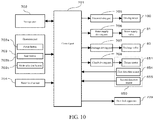
- FIG. 10 is a block diagram illustrating a structure of a drum washing machine 1.
- the drum washing machine 1 further includes: a control part 701, a storage part 702, an operation part 703, a water level sensor 704, a motor driving part 705, a water supply driving part 706, a drainage driving part 707, a clutch driving part 708 and a door lock apparatus 709.
- the operation part 703 includes: a power button 703a, a start button 703b and a mode selection button 703c.
- the power button 703a is a button for turning on and turning off a power supply of the drum washing machine 1.
- the start button 703b is a button for starting the operation.
- the mode selection button 703c is a button for selecting any operation mode from a plurality of operation modes for the washing operation.
- the operation part 703 outputs an input signal corresponding to a button operated by a user to the control part 701.
- the water level sensor 704 detects a water level in the outer drum 20, and outputs a water level detection signal corresponding to the detected water level to the control part 701.
- the motor driving part 705 supplies a driving current to the driving motor 100 according to a control signal from the control part 701.
- the motor driving part 705 includes a speed sensor for detecting the rotating speed of the driving motor 100, a frequency converter circuit and the like, and adjusts the driving current so that the driving motor 100 rotates at the rotating speed set by the control part 701.
- PWM control is used as motor driving control.
- the control part 701 applies a pulse voltage of a duty ratio determined based on a detected rotating speed to the driving motor 100, so as to supply the driving current corresponding to the pulse voltage to the driving motor 100.
- the water supply driving part 706 provides a driving current to the water supply valve 51 according to a control signal from the control part 701.
- the drainage driving part 707 provides a driving current to the drainage valve 40 according to a control signal from the control part 701.
- the clutch driving apparatus 650 includes a first detection sensor 654 and a second detection sensor 655.
- the first detection sensor 654 detects that the driving mode of the driving unit 30 is switched to the biaxial driving mode, and outputs a detection signal to the control part 701.
- the second detection sensor 655 detects that the driving mode of the driving unit 30 is switched to the uniaxial driving mode, and outputs a detection signal to the control part 701.
- the clutch driving part 708 provides a driving current to the torque motor 651 based on the detection signals from the first detection sensor 654 and the second detection sensor 655 and the control signal outputted from the control part 701.
- the door lock apparatus 709 locks and unlocks a door 12 according to a control signal from the control part 701.
- the storage part 702 includes an electrically erasable programmable read only memory (EEPROM), a random access memory (RAM) and the like.
- EEPROM electrically erasable programmable read only memory
- RAM random access memory
- the storage part 702 stores programs for executing the washing operation of various washing operation modes.
- the storage part 702 stores various parameters and various control marks for the execution of the programs.
- the control part 701 controls the motor driving part 705, the water supply driving part 706, the drainage driving part 707, the clutch driving part 708, the door lock apparatus 709 and the like according to the programs stored in the storage part 702 based on the signals from the operation part 703, the water level sensor 704 and the like.
- the drum washing machine 1 performs the washing operation of various operation modes according to the selection operation implemented by the user through the mode selection button 703c.
- the washing operation executes a washing process, an intermediate dewatering process, a rinsing process and a final dewatering process in sequence. It should be noted that the intermediate dewatering process and the rinsing process are sometimes performed more than two times depending on the operation modes.
- the driving mode of the driving unit 30 is switched to the biaxial driving mode.
- Water is stored in the outer drum 20 to a predetermined position which is lower than a lower edge of the laundry inlet 11 in such a manner that the laundry in the drum 22 is immersed in the water.
- the driving motor 100 alternately performs forward rotation and backward rotation.
- the drum 22 and the stirring body 24 alternately perform forward rotation and backward rotation in such a state that the rotating speed of the stirring body 24 is higher than the rotating speed of the drum 22.
- the drum 22 rotates at a rotating speed through which the centrifugal force applied to the laundry is smaller than gravity.
- the laundry in the drum 22 is lifted and dropped down through the baffles 23 and thrown to an inner circumferential surface of the drum 22.
- the laundry contacts blades 24a of the stirring body 24 which is rotating, and the laundry is rubbed by the blades 24a or stirred by the blades 24a.
- the laundry is washed or rinsed.
- the driving mode of the driving unit 30 is switched to the uniaxial driving mode.
- the driving motor 100 i.e., the drum 22
- the stirring body 24 rotate integrally at a rotating speed through which the centrifugal force applied to the laundry in the drum 22 is higher than the gravity.
- the laundry is pressed against the inner circumferential surface of the drum 22 through the effect of the centrifugal force and is dewatered.
- the driving mode of the driving unit 30 is switched from the biaxial driving mode to the uniaxial driving mode.
- the driving mode of the driving unit 30 is switched from the uniaxial driving mode to the biaxial driving mode.
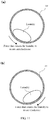
- FIG. 11(a) is a schematic diagram illustrating a case that the laundry in the drum 22 is biased to a left side when observed from the front side
- FIG. 11(b) is a schematic diagram illustrating a case that the laundry in the drum is biased to a right side when observed from the front side.
- the teeth 611a of the spline 611 of the clutch body 610 and the teeth 534a of the spline 534 of the clutch carrying plate 530 are engaged in a state of being strongly pressed to one side, and the frictional resistance between pressed surfaces of the teeth 611a and 534a is increased.
- the driving mode is the uniaxial driving mode
- the engaging protrusion 613b of the engaging part 613 of the clutch body 610 and the engaging recess 132b of the engaged part 132 of the clutch carrying part 130 are engaged in a state of being strongly pressed to one side; and frictional resistance between pressed surfaces of the engaging protrusion 613b and the engaging recess 132b is increased.
- the clutch body 610 is pushed to the bearing unit 500 side through the clutch lever 630 in order to switch from the uniaxial driving mode to the biaxial driving mode
- the engaging protrusion 613b and the engaging recess 132b are difficult to disengage. Therefore, it is possible that switching from the uniaxial driving mode to the biaxial driving mode may not be performed smoothly.
- the driving control of the clutch driving apparatus 650 and the driving motor 100 which are used for smoothly switching the driving mode of the driving unit 30 is executed by the control part 701.
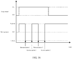
- FIG. 12 is a timing diagram illustrating an energizing action of the torque motor 651 and the driving motor 100 of the clutch driving apparatus 650 while switching the driving mode of the drive unit 30.
- the control part 701 energizes the driving motor 100 in a right rotation manner and rotates the rotor 110 clockwise, and then the driving motor 100 is deenergized. Thereafter, after the control part 701 immediately energizes the driving motor 100 in a left rotation manner without interposing the stopping period and rotates the rotor 110 anticlockwise, the driving motor 100 is deenergized. Then, further, after the control part 701 immediately energizes the driving motor 100 in a right rotation manner without interposing a stopping period and rotates the rotor 110 clockwise, the driving motor 100 is deenergized.
- the driving motor 100 is deenergized.
- the control part 701 immediately energizes the driving motor 100 in a right rotation manner without interposing a stopping period. Then, in order to conduct washing, rinsing, dewatering and the like after the driving mode is switched, the driving motor 100 is continuously energized and the rotor 110 continuously rotates.
- the control part 701 enables the torque motor 651 to operate. Namely, as shown in FIG. 12 , after the control part 701 energizes the driving motor 100 in the right rotation manner initially until the driving motor 100 is deenergized, the torque motor 651 is energized. Then, the control part 701 deenergizes the torque motor 651 according to the detection of the first detection sensor 654 when switching from the uniaxial driving mode to the biaxial driving mode, and deenergizes the torque motor 651 according to the detection of the first detection sensor 654 when switching from the biaxial driving mode to the uniaxial driving mode. However, in either case, the torque motor 651 is deenergized after the driving motor 100 is finally energized in the right rotation manner.
- the driving motor 100 and the torque motor 651 are operated through such timing, so that a reverse action 1 and a reverse action 2 are respectively repeated twice during the operation of the torque motor 651 (i.e., during a movement action of the clutch body 610 performed through the moving mechanism part DM).
- the reverse action 1 is an action of stopping the rotor 110 that is rotating in the clockwise direction and then immediately enabling the rotor 110 to rotate along the anticlockwise direction
- the reverse action 2 is an action of stopping the rotor 110 that is rotating in the anticlockwise direction and then immediately enabling the rotor 110 to rotate along the clockwise direction.
- the rotor 110 of the driving motor 100 immediately rotates in the anticlockwise direction after stopping, and then the spline 611 and the engaged part 132 are about to rotate in a direction weakening the force that presses the teeth 611a and the teeth 534a as well as the engaging protrusion 613b and the engaging recess 132b towards one side. Therefore, the spline 611 and the spline 534 and the engaging part 613 and the engaged part 132 are more difficult to disengage.
- the teeth 611a and 534a of the splines 611 and 534 are abutted with each other rather than engaged with each other, and then, positions of the teeth 611a and 534a are staggered through the rotation of the driving motor 100 and the clutch body 610 rapidly moves to the clutch carrying plate 530 side, so that the teeth 611a and 534a are mutually engaged.
- the bearing-side cushioning member 540 is sandwiched by the bearing part 510 and the clutch carrying plate 530 through the flange part 541 and is fixed to the clutch carrying plate 530 side. Therefore, the bearing-side cushioning member 540 is easily fixed to the clutch carrying plate 530 side without using a screw and the like.
- the engaging protrusion 613b is not engaged with the engaging recess 132b but is abutted against the surface 132a of the engaged part 132, and then, the positions of the engaging protrusion 613b and the engaging recess 132b are coincided through the rotation of the driving motor 100, the clutch body 610 rapidly moves to the clutch carrying part 130 side and the engaging protrusion 613b and the engaging recess 132b are engaged.
- the claw part 681 of the rotor-side cushioning member 680 is locked to the hole part 614 formed in the clutch body 610 so that the rotor-side cushioning member 680 is fixed to the clutch body 610 side. Therefore, the rotor-side cushioning member 680 is easily fixed to the clutch body 610 side without using a screw and the like.
- the rotor 110 of the driving motor 100 rotates clockwise and anticlockwise respectively, so as to respectively execute an action of enabling the rotor 110 rotating along the clockwise direction to stop, and an action of enabling the rotor 110 rotating along the anticlockwise direction to stop when the clutch body 610 moves through the moving mechanism part DM.
- the engaging part 613 of the clutch body 610 and the engaged part 132 of the clutch carrying part 130 are easy to disengage, and when switching from the biaxial driving mode to the uniaxial driving mode, the spline 611 of the clutch body 610 and the spline 534 of the clutch carrying plate 530 are also easy to disengage. Therefore, with the present embodiment, the switching of the driving mode between the uniaxial driving mode and the biaxial driving mode can be conducted smoothly.
- a load applied to the torque motor 651 may be increased. According to the present embodiment, the load applied to the torque motor 651 can be prevented from increasing.
- the clutch lever 630 does not move unless the engaging part 613 and the engaged part 132 are disengaged, so that the operation of the torque motor 651 is ended only when the spring 661 of the relay rod 660 is in an elongated state.
- the driving motor 100 rotates for washing and the like, since the force used to press the engaging protrusion 613b and the engaging recess 132b towards one side is weakened, the engaging protrusion 613b and the engaging recess 132b are easy to disengage.
- the spring 661 rapidly contracts while the clutch lever 630 vigorously moves, the clutch body 610 is vigorously pushed by the clutch lever 630 and is fiercely collided with the clutch carrying plate 530, thereby generating a large impact sound.
- the clutch lever 630 moves through the action of the torque motor 651 when the clutch spring 620 contracts.
- the clutch spring 620 is rapidly elongated; the clutch body 610 is vigorously pushed by the clutch spring 620 and is fiercely collided with the clutch carrying part 130, thereby generating a large impact sound.
- the spline 611 and the spline 534 can be disengaged smoothly, and the engaging part 613 and the engaged part 132 can be disengaged smoothly, the large impact sound can be avoided between the clutch body 610 and the clutch carrying plate 530 and between the clutch body 610 and the clutch carrying part 130.
- the rotor 110 of the driving motor 100 after the rotor 110 of the driving motor 100 is stopped from rotating in a direction, the rotor 110 immediately rotates in an opposite direction without interposing the stopping period, so the force used to press the teeth 611a of the spline 611and the teeth 534a of the spline 534 as well as the engaging protrusion 613b of the engaging part 613 and the engaging recess 132b of the engaged part 132 towards one side can be further weakened, and the spline 611 and the spline 534 as well as the engaging part 613 and the engaged part 132 become easier to disengage.
- the torque motor 651 starts to operate (i.e., the moving action of the clutch body 610 of the moving mechanism part DM is started) after the rotor 110 of the driving motor 100 initially starts to rotate along the clockwise direction
- an action of stopping the rotation of the rotor 110 along the clockwise direction is rapidly conducted after the moving action of the clutch body 610 is started, such that the spline 611 and the spline 534 as well as the engaging part 613 and the engaged part 132 become easier to disengage.
- the bearing-side cushioning member 540 is placed on the clutch carrying plate 530 side.
- a bearing-side cushioning member 690 can also be placed on the clutch body 610 side to replace the bearing-side cushioning member 540.
- FIG. 13 is a sectional view illustrating an essential part enlarging a periphery of a clutch body 610according to a modified embodiment.
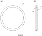
- FIG. 14(b) are respectively a front view and a side sectional view illustrating a bearing-side cushioning member 690 involved in a modified embodiment.
- the bearing-side cushioning member 690 is formed into a circular shape by rubber and other elastic members. cushioning memberAn annular groove part 691 is formed in the center of the bearing-side cushioning member 690.
- the bearing-side cushioning member 690 is fixed to the clutch body 610 by embedding the groove part 691 into the flange part 612 of the clutch body 610.
- the rotor-side cushioning member 680 is provided on the clutch body 610 side.
- a rotor-side cushioning member 140 may be provided on the clutch carrying part 130 sidecushioning member.
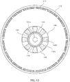
- FIG. 15 is a front view illustrating a rotor 110 of a driving motor 100 involved in a modified embodiment.
- the rotor-side cushioning member 140 is formed into an annular shape by elastic member such as rubber, and is fixed by attaching to the touch surface 133 of the clutch carrying part 130 side and other fixation methods.
- the engaging part 613 of the clutch body 610 and the engaged part 132 of the clutch carrying part 130 are engaged, the rotor-side cushioning member 140 firstly hits the clutch body 610.
- the impact sound between the clutch body 610 side and the clutch carrying part 130 side can be reduced.
- the torque motor 651 is energized. Namely, after the rotor 110 of the driving motor 100 initially starts to rotate along the clockwise direction, the moving action of the clutch body 610is started by the moving mechanism part DM.
- the control part 701 can also energize the torque motor 651 almost at the same time of initial energization of the driving motor 100 in the right rotation manner. Namely, the moving action of the clutch body 610 can be started through the moving mechanism part DM almost at the same time that the rotor 110 of the driving motor 100 initially starts to rotate along the clockwise direction.
- the rotor 110 of the driving motor 100 after the rotor 110 of the driving motor 100 is stopped from rotating along one direction, the rotor 110 immediately rotates along an opposed direction without interposing a stopping period. However, after the rotor 110 of the driving motor 100 is stopped from rotating along one direction, the rotor 110 is stopped for a stopping period and then rotates along an opposed direction.
- the rotor 110 of the driving motor 100 may firstly rotate anticlockwise.
- the drum shaft 300 is fixed to the internal gear 420, and the clutch body 610 is connected with the planetary carrier shaft 441 (i.e., the planetary carrier 440).
- the planetary carrier shaft 441 i.e., the planetary carrier 440.
- a shaft part 421 with a top end part protruding rearward from the drum shaft 300 is installed on the internal gear 420.
- the clutch body 610 is connected with the shaft part 421. Namely, the clutch body 610 is connected with the internal gear 420 via the shaft part 421.
- the planetary gear 430 is modified to have only a first gear. In the biaxial driving mode, when the wing shaft 200 rotates in such a state that the internal carrier 420 is fixed by the clutch body 610, the planetary gear 430 rotates and revolves along with the rotation of the sun gear 410 and the planetary carrier 440 rotates at a rotating speed lower than the rotating speed of the sun gear 410. Thus, the drum shaft 300 fixed to the planetary carrier 440 rotates.
- the rotor 110 of the driving motor 100 is directly coupled with the stirring body 24 through the wing shaft 200, and the stirring body 24 rotates at a rotating speed equal to the rotating speed of the driving motor 100.
- a speed reducing mechanism that uses a gear can also be interposed, like the drum 22, between the stirring body 24 and the driving motor 100.
- the stirring body 24 can rotate more rapidly than the drum 22 by making a speed reducing ratio of the speed reducing mechanism of the stirring body 24 is smaller than a speed reducing ratio of the planetary gear mechanism 400.
- the drum 22 rotates about an inclined axis inclined relative to a horizontal direction.
- the drum washing machine 1 can also adopt a structure in which the drum 22 rotates about a horizontal axis.
- drum washing machine 1 in above embodiments does not have a drying function
- the present disclosure can also be applied to a drum washing machine having the drying function, i.e., a drum washing and drying machine.
Landscapes
- Engineering & Computer Science (AREA)
- Textile Engineering (AREA)
- Main Body Construction Of Washing Machines And Laundry Dryers (AREA)
- Control Of Washing Machine And Dryer (AREA)
Abstract
Description
- The present disclosure relates to a drum washing machine, which not only can be continuously operated from washing to drying, but also can carry out washing without drying.
- In the past, in a drum washing machine, a transverse-shaft type drum is rotated in an outer drum which stores water at a bottom, washings are lifted up and dropped down by baffles arranged in the drum, and the washings are thrown to an inner circumferential surface of the drum to realize washing. In such a configuration in which the washings are stirred by the baffles, it is difficult for the washings to intertwine with each other or rub against each other.. Therefore, with respect to the drum washing machine, in order to improve the cleaning performance, the following structure can be adopted: a stirring body is arranged on a rear surface of the drum, so that the drum and the stirring body can independently rotate at different rotating speeds during washing and rinsing (see a patent literature 1).
- During dewatering of the drum washing machine, the drum and the stirring body integrally rotate at the same rotating speed. Therefore, a clutch mechanism part for switching a driving mode between a first mode in which the drum and the stirring body independently rotate and a second mode in which the drum and the stirring body integrally rotate is arranged.
- The drum and the stirring body are rotationally driven by a driving motor. A rotating shaft of the drum is connected with a planetary carrier of a planetary gear mechanism, and the rotation of the driving motor is transferred to the drum by virtue of the planetary gear mechanism. The clutch mechanism part includes a clutch body and a moving mechanism part. The clutch body is connected with an internal gear that forms the planetary gear mechanism in a manner that the clutch body cannot rotate relative to the internal gear. The moving mechanism part enables the clutch body to move between a driving motor side and a bearing unit side of the rotating shaft supporting the drum freely and rotationally. Splines are formed on the clutch body, at the rotor side end and at the bearing unit side end along a circumferential direction, and splines corresponding to the spline on the clutch body are formed on the rotor and the bearing unit.
- The splines of the clutch body are engaged with the splines of the bearing unit in the first mode. Thus, the internal gear is fixed to the bearing unit by virtue of the clutch body in a manner that the internal gear cannot circumferentially rotate. When the rotor rotates in the state, the drum rotates independently of the stirring body at a rotating speed lower than that of the stirring body according to a reduction ratio of the planetary gear mechanism. In another aspect, the splines of the clutch body are engaged with the splines of the rotor in the second mode. Thus, the internal gear is fixed to the rotor by virtue of the clutch body. The drum integrally rotates with the stirring body at a rotating speed equal to that of the stirring body when the rotor rotates in this state.
- The following condition may occur in the above drum washing machine: when the clutch body moves to the bearing unit side through the moving mechanism part, teeth of the splines of the clutch body and teeth of the splines of the bearing unit are abutted with each other rather than engaged. In this state, the clutch body is continuously pushed to the bearing unit side by the moving mechanism part. In this state, when the clutch body rotates through the internal gear along with the rotation of the rotor and a position of the tooth of the spline of the clutch body is shifted to a position not affected by the tooth of the spline of the bearing unit, the clutch body suddenly moves to the bearing unit side, so that the teeth of the splines are mutually engaged. However, impact sound which is harsh for a user may be generated between the clutch body and the bearing unit.
- Similarly, when the clutch body moves to the rotor side through the moving mechanism part, teeth of the splines may also be abutted with each other rather than engaged. In this state, the clutch body is continuously pushed to the rotor side by the moving mechanism part. In this state, when a position of the tooth of the spline of the rotor is shifted to a position not affected by the tooth of the spline of the clutch body along with the rotation of the rotor, the clutch body suddenly moves to the rotor side, so that the teeth of the splines are mutually engaged. However, impact sound which is harsh for a user may be generated between the clutch body and the rotor.
- Patent Literature 1: Japanese Laid-Open Patent Publication No.
2015-167663 - The present disclosure is completed in view of the above problems. A purpose of the present disclosure is as follows: for a drum washing machine with a rotating body on a rear part of a drum, sound generated when a driving mode is switched between a first mode in which the drum and the rotating body independently rotate and a second mode in which the drum and the rotating body integrally rotate.
- A drum washing machine according to a first mode of the present disclosure includes: an outer drum arranged in a housing; a drum arranged in the outer drum and rotatable about a horizontal axis or an inclined axis inclined with respect to a horizontal direction; a rotating body arranged in a rear part of the drum, wherein a surface of the rotating body is provided with a baffle for contacting laundry; and a driving part configured to rotate the drum and the rotating body. The driving part includes: a driving motor; a first rotating shaft configured to transmit rotation of the driving motor to the rotating body; a second rotating shaft coaxially arranged with the first rotating shaft and configured to transmit the rotation of the driving motor to the drum; a planetary gear mechanism, including a sun gear rotating along with the rotation of the driving motor, an annular internal gear surrounding the sun gear, a plurality of planetary gears interposed between the sun gear and the internal gear, and a planetary carrier free rotatably holding the plurality of planetary gears, where one of the planetary carrier and the internal gear is fixed to the second rotating shaft; and a clutch mechanism part, configured to switch a driving mode of the driving part between a first mode and a second mode. The first mode is a driving mode in which the first rotating shaft and the second rotating shaft independently rotate, and the second mode is a driving mode in which the first rotating shaft and the second rotating shaft integrally rotate. The clutch mechanism part includes: a clutch body, connected to the other one of the planetary carrier and the internal gear in such a state that the clutch body is rotatable together with the other one of the planetary carrier and the internal gear and is moveable towards an axis direction of the second rotating shaft; a moving mechanism part, configured to enable the clutch body to move to a first position when switching to the first mode, and enable the clutch body to move to a second position when switching to the second mode; a first engaging part with a concave-convex shape and a second engaging part with a concave-convex shape formed in the clutch body; a first engaged part formed in a fixing part which does not rotate along with the driving motor, wherein the first engaged part has a concave-convex shape corresponding to the concave-convex shape of the first engaging part and is engaged with the first engaging part along a circumferential direction when the clutch body moves to the first position; a second engaged part formed in a rotating part which rotates along with the driving motor, where the second engaged part has a concave-convex shape corresponding to the concave-convex shape of the second engaging part and is engaged with the second engaging part along the circumferential direction when the clutch body moves to the second position; and a fixing part-side cushioning member is arranged on the clutch body side or the fixing part side. The fixing part-side cushioning member firstly touches an object side when the first engaging part and the first engaged part are engaged, so as to reduce an impact force generated between the clutch body and the fixing part.
- When the clutch body is moved to the first position and the first engaging part and the first engaged part are engaged along the circumferential direction, the other party connected with the clutch body, such as the planetary carrier, does not rotate, and the driving mode is switched to the first mode. When the driving motor rotates, one party (such as the second rotating shaft connected with internal gear) rotates at a rotating speed different from the rotating speed of the first rotating shaft according to a reduction ratio of the planetary gear mechanism. Thus, the drum and the rotating body independently rotate at different rotating speeds.
- In another aspect, when the clutch body is moved to the second position and the second engaging part and the second engaged part are engaged along the circumferential direction, the other party connected with the clutch body rotates along with the driving motor, and the driving mode is switched to the second mode. When the driving motor rotates, the second rotating shaft rotates at a rotating speed equal to the rotating speed of the first rotating shaft. Thus, the drum and the rotating body integrally rotate at the same rotating speed.
- According to the above structure, the fixing part-side cushioning member provided on the clutch body side or the fixing part side firstly touches the object side when the first engaging part and the first engaged part are engaged, such that the impact force generated between the clutch body and the fixing part is reduced. Therefore, impact sound generated between the clutch body side and the fixing part side can be reduced.
- In the drum washing machine in this mode, the driving part can also include a bearing part that free rotatably supports the second rotating shaft. In this case, the fixing part is mounted on the bearing part. The fixing part-side cushioning member is mounted on the fixing part side, and has a flange part sandwiched by the fixing part and the bearing part.
- According to the above structure, the fixing part-side cushioning member is fixed to the fixing part side through the flange part which is clamped by the bearing part and the fixing part. Therefore, the fixing part-side cushioning member is easily fixed to the fixing part side.
- In the drum washing machine in this mode, a rotating part-side cushioning member may be arranged on either the clutch body side or the rotating part side. The rotating part-side cushioning member firstly touches the object side when the second engaging part and the second engaged part are engaged, so as to reduce an impact force generated between the clutch body and the rotating part.
- According to the above structure, the rotating part-side cushioning member arranged on the clutch body side or the rotating part side firstly touches the object side when the second engaging part and the second engaged part are engaged, and the impact force generated between the clutch body and the rotating part is weakened. Therefore, the impact sound generated between the clutch body side and the rotating part side can be reduced.
- A drum washing machine in a second mode of the present disclosure includes: an outer drum arranged in a housing; a drum arranged in the outer drum and is rotatable about a horizontal axis or an inclined axis inclined with respect to a horizontal direction; a rotating body arranged in a rear part of the drum, wherein a surface of the rotating body is provided with a baffle for contacting laundry; and a driving part configured to rotate the drum and the rotating body. The driving part includes: a driving motor; a first rotating shaft configured to transmit rotation of the driving motor to the rotating body; a second rotating shaft coaxially arranged with the first rotating shaft and configured to transmit the rotation of the driving motor to the drum; a planetary gear mechanism, including a sun gear rotating along with the rotation of the driving motor, an annular internal gear surrounding the sun gear, a plurality of planetary gears interposed between the sun gear and the internal gear, and a planetary carrier free rotatably holding the plurality of planetary gears, where one of the planetary carrier and the internal gear is fixed to the second rotating shaft; and a clutch mechanism part, configured to switch a driving mode of the driving part between a first mode and a second mode. The first mode is a driving mode in which the first rotating shaft and the second rotating shaft independently rotate, and the second mode is a driving mode in which the first rotating shaft and the second rotating shaft integrally rotate. The clutch mechanism part includes: a clutch body, connected to the other one of the planetary carrier and the internal gear in such a state that the clutch body is rotatable together with the other one of the planetary carrier and the internal gear and is moveable towards an axis direction of the second rotating shaft; a moving mechanism part, configured to enable the clutch body to move to a first position when switching to the first mode, and enable the clutch body to move to a second position when switching to the second mode; a first engaging part with a concave-convex shape and a second engaging part with a concave-convex shape which are formed in the clutch body; a first engaged part which is formed in a fixing part that does not rotate along with the driving motor, wherein the first engaged part has a concave-convex shape corresponding to the concave-convex shape of the first engaging part and is engaged with the first engaging part along a circumferential direction when the clutch body moves to the first position; a second engaged part which is formed in a rotating part that rotates along with the driving motor, where the second engaged part has a concave-convex shape corresponding to the concave-convex shape of the second engaging part and is engaged with the second engaging part along the circumferential direction when the clutch body moves to the second position; and a rotating part-side cushioning member arranged on the clutch body side or the rotating part side. The rotating part-side cushioning member firstly touches an object side when the second engaging part and the second engaged part are engaged, so as to reduce an impact force generated between the clutch body and the rotating part..
- According to the above structure, the impact sound generated between the clutch body side and the rotating part side can also be reduced like the drum washing machine in the first mode.
- The drum washing machine in the first mode or the second mode can adopt the following structure: the rotating part-side cushioning member is arranged on the clutch body side and has a claw part, and the clutch body has a hole part for inserting and locking the claw part.
- According to the above structure, the rotating part-side cushioning member is fixed to the clutch body side by locking the claw part of the rotating part-side cushioning member to the hole part of the clutch body. Therefore, the rotating part-side cushioning member can be easily fixed to the clutch body side.
- According to the present disclosure, the sound generated when the driving mode is switched between the first mode in which the drum and the rotating body independently rotate and the second mode in which the drum and the rotating body integrally rotate.
- Effects and significances of the present disclosure are further clarified by embodiments shown below. However, the following embodiments are merely examples for implementing the present disclosure, and the present disclosure is not limited by any content described in the following embodiments.
-
-
FIG. 1 is a side sectional view illustrating a structure of a drum washing machine involved in an embodiment; -
FIG. 2 is a sectional view illustrating a structure of a driving unit involved in an embodiment; -
FIG. 3 is a sectional view illustrating a structure of a driving unit involved in an embodiment; -
FIG. 4 is a sectional view illustrating an essential part enlarging a periphery of a clutch body involved in an embodiment; -
FIG. 5 is a sectional view illustrating an essential part enlarging a periphery of a clutch body involved in an embodiment; -
FIG. 6 is a front view illustrating a rotor of a driving motor involved in an embodiment; -
FIG. 7(a) and FIG. 7(b) are respectively a front view and a rear view illustrating a clutch carrying plate involved in an embodiment, andFIG. 7(c) is a front view illustrating a bearing-side cushioning member; -
FIG. 8(a) to FIG. 8(c) are respectively a front view, a side longitudinal sectional view and a rear view illustrating a clutch body involved in an embodiment, andFIG. 8(d) is a sectional view illustrating a planetary carrier shaft involved in an embodiment; -
FIG. 9(a) is a state transition diagram illustrating an engagement state of a spline of a clutch body and a spline of a clutch carrying plate when switching from a uniaxial driving mode to a biaxial driving mode involved in an embodiment, andFIG. 9(b) is a state transition diagram illustrating an engagement state of an engaging part of a clutch body and an engaged part of a clutch carrying part when switching from a biaxial driving mode to a uniaxial driving mode involved in an embodiment; -
FIG. 10 is a block diagram illustrating a structure of a drum washing machine involved in an embodiment; -
FIG. 11(a) is a schematic diagram illustrating a case that the laundry in a drum is biased to a left side when observed from the front side involved in an embodiment, andFIG. 11(b) is a schematic diagram illustrating a case that the laundry in a drum is biased to a right side when observed from the front side involved in an embodiment; -
FIG. 12 is a timing diagram illustrating an energizing action of a torque motor and a driving motor of a clutch driving apparatus while switching driving modes of a drive unit involved in an embodiment; -
FIG. 13 is a sectional view illustrating an essential part enlarging a periphery of a clutch body involved in a modified embodiment; -
FIG. 14(a) and FIG. 14(b) are respectively a front view and a side sectional view illustrating a bearing-side cushioning member involved in a modified embodiment; -
FIG. 15 is a front view illustrating a rotor of a driving motor involved in a modified embodiment; -
FIG. 16 is a timing diagram illustrating an energizing action of a torque motor and a driving motor of a clutch driving apparatus while switching driving modes of a drive unit involved in a modified embodiment; and -
FIG. 17 is a sectional view illustrating a drive unit involved in a modified embodiment. - Hereinafter, a drum washing machine without a clothes drying function in an embodiment of the present disclosure is described by referring to drawings.
-
FIG. 1 is a side sectional view illustrating a structure of adrum washing machine 1. - The
drum washing machine 1 includes ahousing 10 forming an appearance. Afront surface 10a of thehousing 10 is inclined from a central part to an upper part, and alaundry inlet 11 is formed in the inclined surface. Thelaundry inlet 11 is covered by adoor 12 which is freely opened and closed. - In the
housing 10, anouter drum 20 is elastically supported by a plurality ofvibration dampers 21. Adrum 22 is provided in theouter drum 20 in a free rotation manner. Theouter drum 20 and thedrum 22 are inclined in such a manner that rear surface sides thereof are lowered relative to a horizontal direction. Thus, thedrum 22 rotates about an inclination axis inclined relative to the horizontal direction. Inclination angles of theouter drum 20 and thedrum 22 may be set as about 10 degrees-20 degrees. Anopening part 20a on the front surface of theouter drum 20 and anopening part 22a on the front surface of thedrum 22 are opposed to thelaundry inlet 11, and are opened and closed by thedoor 12, together with thelaundry inlet 11. A plurality ofdewatering holes 22b are formed in an inner circumferential surface of thedrum 22. Further, threebaffles 23 are arranged in the circumferential direction at substantially equal intervals on the inner circumferential surface of thedrum 22. - A stirring
body 24 is freely-rotatably disposed at the rear of thedrum 22. The stirringbody 24 has a substantially disc shape. A plurality ofblades 24a that radially extend from the central part are formed on the surface of the stirringbody 24. The stirringbody 24 coaxially rotates with thedrum 22. The stirringbody 24 is equivalent to a rotating body in the present disclosure, and theblades 24a are equivalent to the baffles in the present disclosure. - A driving
unit 30 capable of generating a torque for driving thedrum 22 and the stirringbody 24 is disposed behind theouter drum 20. The drivingunit 30 is equivalent to a driving part in the present disclosure. The drivingunit 30 enables thedrum 22 and the stirringbody 24 to rotate at different rotating speeds in the same direction in a washing process and a rinsing process. Specifically, the drivingunit 30 enables thedrum 22 to rotate at a rotating speed through which the centrifugal force applied to the laundry in thedrum 22 is smaller than gravity, and enables the stirringbody 24 to rotate at a rotating speed higher than the rotating speed of thedrum 22. In another aspect, the drivingunit 30 enables thedrum 22 and the stirringbody 24 to integrally rotate at a rotating speed through which the centrifugal force applied to the laundry in thedrum 22 is much larger than the gravity in a dewatering process. A detailed structure of the drivingunit 30 is described below. - A
water outlet part 20b is formed in the bottom of theouter drum 20. Adrainage valve 40 is provided in thewater outlet part 20b. Thedrainage valve 40 is connected with adrainage hose 41. When thedrainage valve 40 is opened, water stored in theouter drum 20 is discharged out of the machine by thedrainage hose 41. - A
detergent box 50 is provided on the front upper part of thehousing 10. Adetergent container 50a containing detergents is contained in thedetergent box 50 in a free withdrawal manner. Thedetergent box 50 is connected with awater supply valve 51 provided on the upper rear part of thehousing 10 via asoft water hose 52. In addition, thedetergent box 50 is connected with the upper part of theouter drum 20 through awater filing pipe 53. When thewater supply valve 51 is opened, running water from a faucet is supplied into theouter drum 20 by virtue of thesoft water hose 52, thedetergent box 50 and thewater filing pipe 53. At this moment, the detergents contained in thedetergent container 50a are supplied into theouter drum 20 along with a water flow. - Then, a structure of the driving
unit 30 is described in detail. -
FIG. 2 andFIG. 3 are sectional views illustrating a structure of a drivingunit 30.FIG. 4 andFIG. 5 are sectional views illustrating an essential part enlarging a periphery of aclutch body 610.FIG. 2 andFIG. 4 show the drivingunit 30 when a driving mode of the drivingunit 30 is switched to a biaxial driving mode.FIG. 3 andFIG. 5 show the drivingunit 30 when a driving mode of the drivingunit 30 is switched to a uniaxial driving mode.FIG. 6 is front view illustrating arotor 110 of a drivingmotor 100.FIG. 7(a) and FIG. 7(b) are a front view and a rear view illustrating aclutch carrying plate 530 respectively, andFIG. 7(c) is a front view illustrating a bearing-side cushioning member 540.FIG. 8(a) to FIG. 8(c) are a front view, a side longitudinal sectional view and a rear view illustrating aclutch body 610 respectively, andFIG. 8(d) is a sectional view illustrating aplanetary carrier shaft 441. It should be noted that aclutch lever 630 is not shown inFIG. 4 andFIG. 5 . - The driving
unit 30 includes: a drivingmotor 100, awing shaft 200, adrum shaft 300, aplanetary gear mechanism 400, abearing unit 500 and aclutch mechanism part 600. The drivingmotor 100 generates a torque for driving the stirringbody 24 and thedrum 22. Thewing shaft 200 rotates through the torque of the drivingmotor 100, and transfers the rotation to the stirringbody 24. Theplanetary gear mechanism 400 decelerates the rotation of the wing shaft 200 (i.e., the rotation of therotor 110 of the driving motor 100) and transfers the rotation to thedrum shaft 300. Thedrum shaft 300 rotates coaxially with thewing shaft 200 at the rotating speed reduced by theplanetary gear mechanism 400, and transfers the rotation to thedrum 22. Thebearing unit 500 supports thewing shaft 200 and thedrum shaft 300 in a free rotation manner. Theclutch mechanism part 600 switches the driving mode of the drivingunit 30 between the biaxial driving mode and the uniaxial driving mode. The biaxial driving mode is a driving mode that enables the stirring body 24 (i.e., the wing shaft 200) to rotate at a rotating speed equal to the rotating speed of the drivingmotor 100 and enables the drum 22 (i.e., the drum shaft 300) to rotate at a rotating speed reduced by theplanetary gear mechanism 400. The uniaxial driving mode is a driving mode that enables the stirringbody 24 and the drum 22 (i.e., the wing shaft 200), as well as thedrum shaft 300 and theplanetary gear mechanism 400 to integrally rotate at a rotating speed equal to the rotating speed of the drivingmotor 100. Thewing shaft 200 corresponds to a first rotating shaft in the present disclosure, and thedrum shaft 300 corresponds to a second rotating shaft in the present disclosure. The biaxial driving mode corresponds to a first mode in the present disclosure, and the uniaxial driving mode corresponds to a second mode in the present disclosure. - The driving
motor 100 is an outer rotor type DC brushless motor and includes arotor 110 and astator 120. Therotor 110 is formed in a bottomed cylinder shape and made from reinforced resin which is formed by mixing reinforcing materials such as glass in resin, andpermanent magnets 111 are arranged throughout the entire circumference on the inner circumferential surface of therotor 110. As shown inFIG. 4 ,FIG. 5 andFIG. 6 , aclutch carrying part 130 is integrally formed with therotor 110 on a central part of therotor 110. Theclutch carrying part 130 and the driving motor 100 (i.e., the rotor 110) are rotated together. - The
clutch carrying part 130 includes alug boss part 131, anengaged part 132 and atouch surface 133. Thelug boss part 131 has a substantially trapezoidal cross section and alug boss hole 131a in the central part. Thewing shaft 200 extends through thelug boss hole 131a. Thelug boss hole 131a is communicated with arecess 112 formed in a central of a rear surface of therotor 110. Theengaged part 132 is formed at a periphery of thelug boss part 131, and has a substantially annular shape. A plurality of engagingrecesses 132b recessed towards a side deeper than thesurface 132a of theengaged part 132 are formed along the circumferential direction at substantially equal intervals on theengaged part 132. In this way, a concave-convex shape is formed along the circumferential direction on theengaged part 132 through thesurface 132a and the engagingrecesses 132b. Thetouch surface 133 is arranged between thelug boss part 131 and theengaged part 132, and has a flat surface protruded by a section from thesurface 132a of theengaged part 132. Theclutch carrying part 130 corresponds to a rotating part in the present disclosure, and theengaged part 132 corresponds to a second engaged part in the present disclosure. - A
coil 121 is arranged on an outer circumferential part of thestator 120. When a driving current is supplied to thecoil 121 of thestator 120 from an after-mentioned motor driving part, therotor 110 rotates. - The
drum shaft 300 is of a hollow shape and encloses thewing shaft 200 and theplanetary gear mechanism 400. The central part of thedrum shaft 300 is bulged outwards. The bulged part forms a containing part of theplanetary gear mechanism 400. - The
planetary gear mechanism 400 includes: asun gear 410, an annularinternal gear 420 surrounding thesun gear 410, a plurality of groups ofplanetary gears 430 between thesun gear 410 and theinternal gear 420, and aplanetary carrier 440 holding theplanetary gears 430 in a free rotation manner. - The
sun gear 410 is fixed to thewing shaft 200, and is rotated with the rotation of the drivingmotor 100. Theinternal gear 420 is fixed to thedrum shaft 300. A group ofplanetary gears 430 includes a first gear and a second gear which are engaged mutually and rotated in opposed directions. Theplanetary carrier 440 includes aplanetary carrier shaft 441 extending backwards. Theplanetary carrier shaft 441 is coaxial with thedrum shaft 300, and is internally hollowed to insert thewing shaft 200. - A rear end part of the
wing shaft 200 is protruded backwards from theplanetary carrier shaft 441, and is fixed to thelug boss hole 131a of therotor 110 through an installingbolt 210. A head of the installingbolt 210 is accommodated in therecess 112 of therotor 110, and is not further protruded backwards than therotor 110. - A
cylindrical bearing part 510 is arranged on the central part of thebearing unit 500. In thebearing part 510, rollingbears mechanical seal 513 is arranged on the front end part. An outer circumferential surface of thedrum shaft 300 is carried by the rolling bears 511 and 512, and rotates smoothly in thebearing part 510. In addition, themechanical seal 513 is used to prevent water from entering a place between thebearing part 510 and thedrum shaft 300. - A fixing
flange part 520 is formed around the bearingpart 510 of thebearing unit 500. An installinglug boss 521 is formed on a lower end part of the fixingflange part 520. - A
clutch carrying plate 530 is installed on a rear end part of thebearing part 510. As shown inFIG. 4 ,FIG. 5 andFIG. 7(a) and FIG. 7(b) , theclutch carrying plate 530 is made of reinforced resin that is same as the reinforced resin of therotor 110, and includes a carryingbody part 531, aflange part 532 and apressing part 533. The carryingbody part 531 is formed in a flat cylindrical shape, and has aspline 534 on an inner side surface. Eachtooth 534a of thespline 534 is formed along the circumferential direction of the carryingbody part 531 at substantially equal intervals, and is protruded to an inner side of the carryingbody part 531. Theflange part 532 is formed on an outer circumferential surface of the carryingbody part 531 and has a circular shape. Inserting throughholes 535 through which screws 550 go are formed in multiple positions of theflange part 532. Thepressing part 533 is protruded from the carryingbody part 531 to the rollingbearing 512, and has a circular shape. Theclutch carrying plate 530 corresponds to a fixing part in the present disclosure, and thespline 534 corresponds to the first engaged part in the present disclosure. - The
clutch carrying plate 530 is fixed to a rear end part of thebearing part 510 through thescrew 550. Thescrew 550 goes through the inserting throughhole 535 and is fastened to ascrew hole 514 formed at the rear end part of thebearing part 510. - A bearing-
side cushioning member 540 is provided at an inner circumferential side of the carryingbody part 531 of theclutch carrying plate 530. As shown inFIG. 4 ,FIG. 5 andFIG. 7(c) , the bearing-side cushioning member 540 has a flat cylindrical shape, and is made of rubber or other elastic materials. The bearing-side cushioning member 540 corresponds to the fixed part side cushioning member in the present disclosure. The bearing-side cushioning member 540 has acircular flange part 541. Theflange part 541 is sandwiched between the rollingbearing 512 of thebearing part 510 and thepressing part 533 of theclutch carrying plate 530, and is pressed to the rollingbearing 512 side by thepressing part 533. Thus, the bearing-side cushioning member 540 is fixed to theclutch carrying plate 530 side. The outer circumferential edge of theflange part 541 is provided with an annularprotruding part 541a, and theprotruding part 541a comes into contact with the outer circumferential surface of thepressing part 533 so that theflange part 541 is less likely to come off a part between the rollingbearing 512 and thepressing part 533. Further, aspring carrying part 560 is arranged behind the rollingbearing 512 and at the inner side of the bearing-side cushioning member 540. - The
bearing unit 500 is fixed to a rear surface of theouter drum 20 via the fixingflange part 520 through fixing methods such as screw fastening. In a state that the drivingunit 30 is mounted on theouter drum 20, thewing shaft 200 and thedrum shaft 300 enter theouter drum 20. Thedrum 22 is fixed to thedrum shaft 300, and the stirringbody 24 is fixed to thewing shaft 200. - The
clutch mechanism part 600 includes: aclutch body 610, aclutch spring 620, aclutch lever 630, alever supporting part 640, aclutch driving apparatus 650, arelay rod 660 and an installingplate 670. Theclutch spring 620, theclutch lever 630, thelever supporting part 640, theclutch driving apparatus 650 and therelay rod 660 form a moving mechanism part DM that moves theclutch body 610. - As shown in
FIG. 4 ,FIG. 5 andFIG. 8(a)- FIG. 8(c) , theclutch body 610 is made of the reinforced resin identical with the reinforced resin of therotor 110, and has a substantially disc shape. Anannular spline 611 is formed on an outer circumferential surface at a front end part of theclutch body 610.Teeth 611a of thespline 611 are formed along the circumferential direction of theclutch body 610 at substantially equal intervals, and each are protruded towards the outer side of theclutch body 610. Thespline 611 corresponds to the first engaging part in the present disclosure. In addition, aflange part 612 is formed on the outer circumferential surface of theclutch body 610 and behind thespline 611. - An
engaging part 613 is formed at a rear end part of theclutch body 610. Theengaging part 613 has acircular base surface 613a, and a plurality of engagingprotrusions 613b that protrude backwards are formed along the circumferential direction on thebase surface 613a at substantially equal intervals. The engagingprotrusions 613b have substantially the same shape as the engagingrecesses 132b of theengaged part 132. In this way, theengaging part 613 has a concave-convex shape along the circumferential direction through thebase surface 613a and the engagingprotrusions 613b. Further, the rear end part of theclutch body 610 is provided with a rotor-side cushioning member 680 at the inner side of theengaging part 613. The rotor-side cushioning member 680 is made of elastic materials such as rubber, and has a circular shape. The rotor-side cushioning member 680 is provided with aclaw part 681 formed at multiple places on a depth direction side. cushioningmemberThe claw part 681 of the rotor-side cushioning member 680 is inserted into ahole part 614 formed in the rear end part of theclutch body 610 so that a tip end part of theclaw part 681 is locked to the depth direction side of thehole part 614 and then fixed to theclutch body 610. Theengaging part 613 corresponds to the second engaging part in the present disclosure, and the rotor-side cushioning member 680 corresponds to the rotating part-side cushioning member in the present disclosure. - In the
clutch body 610, in order to prevent theclutch body 610 from hitting thelug boss part 131 of theclutch carrying part 130, a truncated cone-shapedrecess 615 is formed at the inner side of the rotor-side cushioning member 680. In addition, ashaft hole 616 that extends from the front end part of theclutch body 610 to therecess 615 is formed at the center of theclutch body 610. Aspline 616a is formed at theshaft hole 616. In another aspect, as shown inFIG. 8(d) , aspline 441a corresponding to thespline 616a is formed on theplanetary carrier shaft 441. When theplanetary carrier shaft 441 is inserted into theshaft hole 616, thespline 616a is engaged with thespline 441a. Thus, theclutch body 610 is in a state that theclutch body 610 can move in a front-rear direction relative to theplanetary carrier shaft 441 but cannot rotate in the circumferential direction. - An
annular accommodation groove 617 is formed in outside theshaft hole 616 of theclutch body 610. Theaccommodation groove 617 contains aclutch spring 620. One end of theclutch spring 620 is received by thespring receiving part 560, and the other end is received by a bottom surface of theaccommodation groove 617. - The
clutch lever 630 is supported by a supportingshaft 641 arranged on alevel supporting part 640 in a free rotation manner. On an upper end part of theclutch lever 630, apressing part 631 contacting a rear surface of theflange part 612 of theclutch body 610 and configured to push theflange part 612 forwards is formed. In addition, an installingshaft 632 is formed at a lower end part of theclutch lever 630. - The
clutch driving apparatus 650 is provided below theclutch lever 630. Theclutch driving apparatus 650 includes atorque motor 651 and a disc-shapedcam 652 which is rotated about a horizontal axis by a torque of thetorque motor 651. At an upper surface of thecam 652, acamshaft 653 is arranged at an outer circumferential part. A rotation center of thecam 652 and a center of the installingshaft 632 of theclutch lever 630 aligned in the front-rear direction. - The
relay rod 660 extends in a vertical direction and connects theclutch lever 630 and thecam 652. An upper end part of therelay rod 660 is mounted to the installingshaft 632 of theclutch lever 630, and a lower end part is mounted to thecamshaft 653 of thecam 652. Aspring 661 is integrally formed with therelay rod 660 in a middle position of therelay rod 660. Thespring 661 is a tension spring. - The
lever supporting part 640 and theclutch driving apparatus 650 are secured to the installingplate 670 through securing methods such as screw fastening. The installingplate 670 is fixed to an installinglug boss 521 of thebearing unit 500 through a screw. - When the driving mode of the driving
unit 30 is switched from the uniaxial driving mode to the biaxial driving mode, as shown inFIG. 2 , thecam 652 is rotated through the operation of thetorque motor 651 in such a manner that thecamshaft 653 is located at a lowermost part. With the rotation of thecam 652, the lower end part of theclutch lever 630 is pulled downward by therelay rod 660. Theclutch lever 630 rotates forwards about the supportingshaft 641. Thepressing part 631 pushes theclutch body 610 forwards. Theclutch body 610 to moves forward against the elastic force of theclutch spring 620. Thespline 611 of theclutch body 610 and the spline 503 of theclutch carrying plate 530 are engaged along the circumferential direction. - When the
camshaft 653 moves to a predetermined intermediate position, thespline 611 of theclutch body 610 reaches a position where thespline 611 and thespline 534 are engaged. At this moment, thespring 661 of therelay rod 660 is in a state of natural length. Since theclutch body 610 does not move to a position in front of the engaging position, when thecamshaft 653 moves from the predetermined position to the lowermost position, as shown inFIG. 2 , thespring 661 extends downward. In this way, since theclutch lever 630 is pulled by thespring 661 and moves forward, a pressing force is applied by thepressing part 631 to theclutch body 610 in the engaging position. Thus, thespline 611 and thespline 534 are firmly engaged. - When the
spline 611 and thespline 534 are engaged, since theclutch body 610 is in a state that theclutch body 610 cannot rotate relative to thebearing unit 500, theplanetary carrier shaft 441 of theplanetary gear mechanism 400, i.e., theplanetary carrier 440 is fixed and cannot rotate. In this state, when therotor 110 rotates, thewing shaft 200 rotates at a same rotating speed as that of therotor 110, and the stirringbody 24 connected with thewing shaft 200 also rotates at a same rotating speed as that of therotor 110. For theplanetary gear mechanism 400, thesun gear 410 rotates with the rotation of thewing shaft 200. As mentioned above, since theplanetary carrier 440 is fixed, a first gear and a second gear of theplanetary gear 430 respectively rotate in a same direction and a reverse direction as thesun gear 410, and theinternal gear 420 rotates in a same direction as thesun gear 410. Thus, thedrum shaft 300 fixed to theinternal gear 420 rotates in the same direction as thewing shaft 200 at a rotating speed lower than that of thewing shaft 200, and thedrum 22 fixed to thedrum shaft 300 rotates in the same direction as the stirringbody 24 at a rotating speed lower than that of the stirringbody 24. In other words, the stirringbody 24 rotates in the same direction as thedrum 22 at a rotating speed higher than that of thedrum 22. - In another aspect, when the driving mode of the driving
unit 30 is switched from the biaxial driving mode to the uniaxial driving mode, as shown inFIG. 3 , thecam 652 is rotated through the operation of thetorque motor 651 in such a manner that thecamshaft 653 is located at an uppermost part. When thecam 652 rotates and thecamshaft 653 moves upwards, thespring 661 is contracted first. When thespring 661 returns to the natural length, then with the movement of thecamshaft 653, therelay rod 660 moves upwards, and the lower end part of theclutch lever 630 is pushed by therelay rod 660 and moves upwards. Theclutch lever 630 rotates backwards about the supportingshaft 641, and thepressing part 631 leaves theflange part 612 of theclutch body 610. Theclutch body 610 moves backwards through the elastic force of theclutch spring 620, and theengaging part 613 of theclutch body 610 and theengaged part 132 of theclutch carrying part 130 are engaged along the circumferential direction. - When the
engaging part 613 and theengaged part 132 are engaged, theclutch body 610 can rotate together with therotor 110. In this state, when therotor 110 rotates, thewing shaft 200 and theclutch body 610 rotate at a same rotating speed as that of therotor 110. At this moment, for theplanetary gear mechanism 400, thesun gear 410 and theplanetary carrier 440 rotate at a same rotating speed as that of therotor 110. Thus, theinternal gear 420 rotates at a same rotating speed as that of thesun gear 410 and theplanetary carrier 440, and thedrum shaft 300 fixed to theinternal gear 420 rotates at a same rotating speed as that of therotor 110. Namely, in the drivingunit 30, thewing shaft 200, theplanetary gear mechanism 400 and thedrum shaft 300 integrally rotate. Thus, thedrum 22 and the stirringbody 24 integrally rotate. -
FIG. 9(a) is a state transition diagram illustrating an engagement state of thespline 611 of theclutch body 610 and thespline 534 of theclutch carrying plate 530 when switching from the uniaxial driving mode to the biaxial driving mode, andFIG. 9(b) is a state transition diagram illustrating an engagement state of theengaging part 613 of theclutch body 610 and theengaged part 132 of theclutch carrying part 130 when switching from the biaxial driving mode to the uniaxial driving mode. - When the
clutch body 610 moves to theclutch carrying plate 530 side of thebearing unit 500 in order to switch to the biaxial driving mode, as shown in the left figure inFIG. 9(a) , there is a possibility thatteeth 611a of thespline 611 andteeth 534a of thespline 534 may be not engaged and abut each other. In this state, as mentioned above, theclutch body 610 is continuously pushed by theclutch lever 630 to theclutch carrying plate 530 side. Moreover, in this state, as therotor 110 rotates, due to the connection with thedrum 22, theinternal gear 420 with a large load applied does not rotate, while theplanetary carrier 440 with a small load applied rotates, and theclutch body 610 rotates through theplanetary carrier shaft 441. When theteeth 611a of thespline 611 of theclutch body 610 is moved through the rotation of theclutch body 610 to a position where theteeth 611a of thespline 611 are not obstructed by theteeth 534a of thespline 534 of theclutch carrying plate 530, as shown in the right figure ofFIG. 9(a) , theclutch body 610 rapidly moves to theclutch carrying plate 530 side, and theteeth side cushioning member 540 provided on theclutch carrying plate 530 side firstly comes into contact with the front end part of theclutch body 610 on an object side, the impact force to theclutch carrying plate 530 side of theclutch body 610 is absorbed by the bearing-side cushioning member 540 and is weakened. Thus, an impact sound generated between theclutch body 610 side and theclutch carrying plate 530 side is reduced. - Similarly, when the
clutch body 610 moves to theclutch carrying part 130 side of therotor 110 in order to switch to the uniaxial driving mode, as shown in the left figure inFIG. 9(b) , the engagingprotrusion 613b of theengaging part 613 and theengaging recess 132b of theengaged part 132 may be not engaged, and the engagingprotrusion 613b may be abutted against thesurface 132a of theengaged part 132. In this state, as mentioned above, theclutch body 610 is continuously pushed by theclutch spring 620 to theclutch carrying part 130 side. In this state, as therotor 110 rotates, when theengaging recess 132b of theengaged part 132 is staggered to a position where the engagingrecess 132b is consistent with the engagingprotrusion 613b of theengaging part 613, as shown in the right figure ofFIG. 9(b) , theclutch body 610 rapidly moves to theclutch carrying part 130 side, and the engagingprotrusion 613b is engaged with theengaging recess 132b. At this moment, since the rotor-side cushioning member 680 provided on theclutch body 610 side firstly comes into contact with thetouch surface 133 of clutch carryingpart 130, the impact force to theclutch carrying part 130 side of theclutch body 610 is absorbed by the rotor-side cushioning member 680 and is weakened. Thus, an impact sound generated between theclutch body 610 side and theclutch carrying part 130 side is reduced. - It should be noted that the
rotor 110, theclutch carrying plate 530 and theclutch body 610 are all made of the reinforced resin. Therefore, if the bearing-side cushioning member 540 and the rotor-side cushioning member 680 which are harder than ordinary resin are not arranged, the impact sound between theclutch body 610 side and theclutch carrying plate 530 and the impact sound between theclutch body 610 side and theclutch carrying part 130 side are especially easy to increase. -
FIG. 10 is a block diagram illustrating a structure of adrum washing machine 1. - In addition to the above structure, the
drum washing machine 1 further includes: acontrol part 701, astorage part 702, anoperation part 703, awater level sensor 704, amotor driving part 705, a watersupply driving part 706, adrainage driving part 707, aclutch driving part 708 and adoor lock apparatus 709. - The
operation part 703 includes: apower button 703a, astart button 703b and amode selection button 703c. Thepower button 703a is a button for turning on and turning off a power supply of thedrum washing machine 1. Thestart button 703b is a button for starting the operation. Themode selection button 703c is a button for selecting any operation mode from a plurality of operation modes for the washing operation. Theoperation part 703 outputs an input signal corresponding to a button operated by a user to thecontrol part 701. - The
water level sensor 704 detects a water level in theouter drum 20, and outputs a water level detection signal corresponding to the detected water level to thecontrol part 701. - The
motor driving part 705 supplies a driving current to the drivingmotor 100 according to a control signal from thecontrol part 701. Themotor driving part 705 includes a speed sensor for detecting the rotating speed of the drivingmotor 100, a frequency converter circuit and the like, and adjusts the driving current so that the drivingmotor 100 rotates at the rotating speed set by thecontrol part 701. For example, PWM control is used as motor driving control. In this case, thecontrol part 701 applies a pulse voltage of a duty ratio determined based on a detected rotating speed to the drivingmotor 100, so as to supply the driving current corresponding to the pulse voltage to the drivingmotor 100. - The water
supply driving part 706 provides a driving current to thewater supply valve 51 according to a control signal from thecontrol part 701. Thedrainage driving part 707 provides a driving current to thedrainage valve 40 according to a control signal from thecontrol part 701. - The
clutch driving apparatus 650 includes afirst detection sensor 654 and asecond detection sensor 655. Thefirst detection sensor 654 detects that the driving mode of the drivingunit 30 is switched to the biaxial driving mode, and outputs a detection signal to thecontrol part 701. Thesecond detection sensor 655 detects that the driving mode of the drivingunit 30 is switched to the uniaxial driving mode, and outputs a detection signal to thecontrol part 701. Theclutch driving part 708 provides a driving current to thetorque motor 651 based on the detection signals from thefirst detection sensor 654 and thesecond detection sensor 655 and the control signal outputted from thecontrol part 701. - The
door lock apparatus 709 locks and unlocks adoor 12 according to a control signal from thecontrol part 701. - The
storage part 702 includes an electrically erasable programmable read only memory (EEPROM), a random access memory (RAM) and the like. Thestorage part 702 stores programs for executing the washing operation of various washing operation modes. In addition, thestorage part 702 stores various parameters and various control marks for the execution of the programs. - The
control part 701 controls themotor driving part 705, the watersupply driving part 706, thedrainage driving part 707, theclutch driving part 708, thedoor lock apparatus 709 and the like according to the programs stored in thestorage part 702 based on the signals from theoperation part 703, thewater level sensor 704 and the like. - The
drum washing machine 1 performs the washing operation of various operation modes according to the selection operation implemented by the user through themode selection button 703c. The washing operation executes a washing process, an intermediate dewatering process, a rinsing process and a final dewatering process in sequence. It should be noted that the intermediate dewatering process and the rinsing process are sometimes performed more than two times depending on the operation modes. - In the washing process and the rinsing process, the driving mode of the driving
unit 30 is switched to the biaxial driving mode. Water is stored in theouter drum 20 to a predetermined position which is lower than a lower edge of thelaundry inlet 11 in such a manner that the laundry in thedrum 22 is immersed in the water. In this state, the drivingmotor 100 alternately performs forward rotation and backward rotation. Thus, thedrum 22 and the stirringbody 24 alternately perform forward rotation and backward rotation in such a state that the rotating speed of the stirringbody 24 is higher than the rotating speed of thedrum 22. At this moment, thedrum 22 rotates at a rotating speed through which the centrifugal force applied to the laundry is smaller than gravity. - The laundry in the
drum 22 is lifted and dropped down through thebaffles 23 and thrown to an inner circumferential surface of thedrum 22. In addition, at the rear part of thedrum 22, thelaundry contacts blades 24a of the stirringbody 24 which is rotating, and the laundry is rubbed by theblades 24a or stirred by theblades 24a. Thus, the laundry is washed or rinsed. - During washing and rinsing like this, since not only a mechanical force generated by the rotation of the
drum 22 is applied to the laundry, but also a mechanical force generated by the stirringbody 24 is applied to the laundry, improvement of washing performance can be expected. In the intermediate dewatering process and the final dewatering process, the driving mode of the drivingunit 30 is switched to the uniaxial driving mode. The driving motor 100 (i.e., the drum 22) and the stirringbody 24 rotate integrally at a rotating speed through which the centrifugal force applied to the laundry in thedrum 22 is higher than the gravity. The laundry is pressed against the inner circumferential surface of thedrum 22 through the effect of the centrifugal force and is dewatered. - In this way, during dewatering, since the
drum 22 and the stirringbody 24 rotate integrally, the laundry attached to thedrum 22 does not need to be stirred by the stirringbody 24 and can be well dewatered. - In the
drum washing machine 1 in the present embodiment, at the end of washing and rinsing, after thecontrol part 701 stops the drivingmotor 100 and stops thedrum 22, the driving mode of the drivingunit 30 is switched from the biaxial driving mode to the uniaxial driving mode. In addition, at the end of the intermediate dewatering, after thecontrol part 701 stops the drivingmotor 100 and stops thedrum 22, the driving mode of the drivingunit 30 is switched from the uniaxial driving mode to the biaxial driving mode. -
FIG. 11(a) is a schematic diagram illustrating a case that the laundry in thedrum 22 is biased to a left side when observed from the front side, andFIG. 11(b) is a schematic diagram illustrating a case that the laundry in the drum is biased to a right side when observed from the front side. - Under a condition that the
drum 22 is stopped, as shown inFIG. 11(a) , when the laundry in thedrum 22 is biased to the left side, a force that enables thedrum 22 to rotate anticlockwise plays a role through the biased laundry. In another aspect, as shown inFIG. 11(b) , when the laundry in thedrum 22 is biased to the right side, a force that enables thedrum 22 to rotate clockwise plays a role through the biased laundry. - In this way, under a condition that the laundry in the
drum 22 is biased to the left side or the right side, when the driving mode is the biaxial driving mode, theteeth 611a of thespline 611 of theclutch body 610 and theteeth 534a of thespline 534 of theclutch carrying plate 530 are engaged in a state of being strongly pressed to one side, and the frictional resistance between pressed surfaces of theteeth clutch body 610 by theclutch lever 630 is relieved and theclutch body 610 is pushed to therotor 110 side through theclutch spring 620 in order to switch from the biaxial driving mode to the uniaxial driving mode, theteeth 611a of thespline 611 and theteeth 534a of thespline 534 are difficult to disengage. Therefore, it is possible that switching from the biaxial driving mode to the uniaxial driving mode may not be performed smoothly. - Similarly, under a condition that the laundry in the
drum 22 is biased to the left side or the right side, when the driving mode is the uniaxial driving mode, the engagingprotrusion 613b of theengaging part 613 of theclutch body 610 and theengaging recess 132b of theengaged part 132 of theclutch carrying part 130 are engaged in a state of being strongly pressed to one side; and frictional resistance between pressed surfaces of the engagingprotrusion 613b and theengaging recess 132b is increased. In this way, even if theclutch body 610 is pushed to thebearing unit 500 side through theclutch lever 630 in order to switch from the uniaxial driving mode to the biaxial driving mode, the engagingprotrusion 613b and theengaging recess 132b are difficult to disengage. Therefore, it is possible that switching from the uniaxial driving mode to the biaxial driving mode may not be performed smoothly. - Therefore, in the present embodiment, the driving control of the
clutch driving apparatus 650 and the drivingmotor 100 which are used for smoothly switching the driving mode of the drivingunit 30 is executed by thecontrol part 701. -
FIG. 12 is a timing diagram illustrating an energizing action of thetorque motor 651 and the drivingmotor 100 of theclutch driving apparatus 650 while switching the driving mode of thedrive unit 30. - In both of switching from the uniaxial driving mode to the biaxial driving mode and switching from the biaxial driving mode to the uniaxial driving mode, as shown in
FIG. 12 , thecontrol part 701 energizes the drivingmotor 100 in a right rotation manner and rotates therotor 110 clockwise, and then the drivingmotor 100 is deenergized. Thereafter, after thecontrol part 701 immediately energizes the drivingmotor 100 in a left rotation manner without interposing the stopping period and rotates therotor 110 anticlockwise, the drivingmotor 100 is deenergized. Then, further, after thecontrol part 701 immediately energizes the drivingmotor 100 in a right rotation manner without interposing a stopping period and rotates therotor 110 clockwise, the drivingmotor 100 is deenergized. Then, after thecontrol part 701 immediately energizes the drivingmotor 100 in a left rotation manner without interposing a stopping period and rotates therotor 110 anticlockwise, the drivingmotor 100 is deenergized. Finally, thecontrol part 701 immediately energizes the drivingmotor 100 in a right rotation manner without interposing a stopping period. Then, in order to conduct washing, rinsing, dewatering and the like after the driving mode is switched, the drivingmotor 100 is continuously energized and therotor 110 continuously rotates. - During energizing-deenergizing actions of the driving
motor 100, thecontrol part 701 enables thetorque motor 651 to operate. Namely, as shown inFIG. 12 , after thecontrol part 701 energizes the drivingmotor 100 in the right rotation manner initially until the drivingmotor 100 is deenergized, thetorque motor 651 is energized. Then, thecontrol part 701 deenergizes thetorque motor 651 according to the detection of thefirst detection sensor 654 when switching from the uniaxial driving mode to the biaxial driving mode, and deenergizes thetorque motor 651 according to the detection of thefirst detection sensor 654 when switching from the biaxial driving mode to the uniaxial driving mode. However, in either case, thetorque motor 651 is deenergized after the drivingmotor 100 is finally energized in the right rotation manner. - The driving
motor 100 and thetorque motor 651 are operated through such timing, so that areverse action 1 and areverse action 2 are respectively repeated twice during the operation of the torque motor 651 (i.e., during a movement action of theclutch body 610 performed through the moving mechanism part DM). Thereverse action 1 is an action of stopping therotor 110 that is rotating in the clockwise direction and then immediately enabling therotor 110 to rotate along the anticlockwise direction, and thereverse action 2 is an action of stopping therotor 110 that is rotating in the anticlockwise direction and then immediately enabling therotor 110 to rotate along the clockwise direction. - As shown in
FIG. 11(a) , in a condition that the laundry in thedrum 22 is biased to the left side when thedrum 22 is stopped, if therotor 110 of the drivingmotor 100 rotates in the clockwise direction, thedrum 22 rotates in the clockwise direction opposed to the direction of the force that acts on the biased laundry. Then, when the drivingmotor 100 is stopped, since an inertia force for continuing to rotate in the clockwise direction acts on thedrum 22 at this moment, the force that acts on the biased laundry is offset by the inertia force and is weakened. In this way, when switching from the biaxial driving mode to the uniaxial driving mode, since the force by which theteeth 611a of thespline 611 of theclutch body 610 and theteeth 534a of thespline 534 of theclutch carrying plate 530 are pressed towards one side is weakened, theteeth 611a of thespline 611 becomes easy to separate from theteeth 534a of thespline 534. In addition, when switching from the uniaxial driving mode to the biaxial driving mode, since the force by which the engagingprotrusion 613b of theengaging part 613 of theclutch body 610 and theengaging recess 132b of theengaged part 132 of theclutch carrying part 130 are pressed towards one side is weakened, the engagingprotrusion 613b of theengaging part 613 becomes easy to separate from the engagingrecess 132b of theengaged part 132. - In addition, the
rotor 110 of the drivingmotor 100 immediately rotates in the anticlockwise direction after stopping, and then thespline 611 and theengaged part 132 are about to rotate in a direction weakening the force that presses theteeth 611a and theteeth 534a as well as the engagingprotrusion 613b and theengaging recess 132b towards one side. Therefore, thespline 611 and thespline 534 and theengaging part 613 and theengaged part 132 are more difficult to disengage. - In this way, even if the laundry in the
drum 22 is biased to the left side when thedrum 22 is stopped, tworeverse actions 1 are performed during the operation period of thetorque motor 651, so that thespline 611 and thespline 534 are easy to disengage and theengaging part 613 and theengaged part 132 are also easy to disengage. Similarly, as shown inFIG. 11(b) , even if the laundry in thedrum 22 is biased to the right side when thedrum 22 is stopped, tworeverse actions 2 are performed during the operation period of thetorque motor 651 and the same phenomenon as the tworeverse actions 1 occurs, so that thespline 611 and thespline 534 are easy to disengage and theengaging part 613 and theengaged part 132 are also easy to disengage. Thus, switching from the biaxial driving mode to the uniaxial driving mode can be conducted smoothly, and switching from the uniaxial driving mode to the biaxial driving mode can be conducted smoothly. - As mentioned above, according to the present embodiment, even if the
clutch body 610 moves to theclutch carrying plate 530 side in order to switch to the biaxial driving mode, theteeth splines teeth motor 100 and theclutch body 610 rapidly moves to theclutch carrying plate 530 side, so that theteeth side cushioning member 540 provided on theclutch carrying plate 530 side firstly contacts the front end part of theclutch body 610, the impact force to theclutch carrying plate 530 side of theclutch body 610 is also weakened by the bearing-side cushioning member 540. Thus, an impact sound generated between theclutch body 610 side and theclutch carrying plate 530 side is reduced. - In addition, according to the present embodiment, the bearing-
side cushioning member 540 is sandwiched by the bearingpart 510 and theclutch carrying plate 530 through theflange part 541 and is fixed to theclutch carrying plate 530 side. Therefore, the bearing-side cushioning member 540 is easily fixed to theclutch carrying plate 530 side without using a screw and the like. - Further, according to the present embodiment, even if the
clutch body 610 moves to theclutch carrying part 130 side in order to switch to the uniaxial driving mode, the engagingprotrusion 613b is not engaged with theengaging recess 132b but is abutted against thesurface 132a of theengaged part 132, and then, the positions of the engagingprotrusion 613b and theengaging recess 132b are coincided through the rotation of the drivingmotor 100, theclutch body 610 rapidly moves to theclutch carrying part 130 side and the engagingprotrusion 613b and theengaging recess 132b are engaged. Even in such case, since the rotor-side cushioning member 680 provided on theclutch body 610 side firstly contacts thetouch surface 133 of theclutch carrying part 130 side, the impact force to theclutch carrying part 130 side of theclutch body 610 is also weakened by the rotor-side cushioning member 680. Thus, an impact sound generated between theclutch body 610 side and theclutch carrying part 130 side is reduced. - Further, according to the present embodiment, the
claw part 681 of the rotor-side cushioning member 680 is locked to thehole part 614 formed in theclutch body 610 so that the rotor-side cushioning member 680 is fixed to theclutch body 610 side. Therefore, the rotor-side cushioning member 680 is easily fixed to theclutch body 610 side without using a screw and the like. - Further, according to the present embodiment, in both switching from the uniaxial driving mode to the biaxial driving mode and switching from the biaxial driving mode to the uniaxial driving mode, the
rotor 110 of the drivingmotor 100 rotates clockwise and anticlockwise respectively, so as to respectively execute an action of enabling therotor 110 rotating along the clockwise direction to stop, and an action of enabling therotor 110 rotating along the anticlockwise direction to stop when theclutch body 610 moves through the moving mechanism part DM. Thus, even if the laundry in thedrum 22 is biased to either the left side or the right side when thedrum 22 is stopped, when switching from the uniaxial driving mode to the biaxial driving mode, theengaging part 613 of theclutch body 610 and theengaged part 132 of theclutch carrying part 130 are easy to disengage, and when switching from the biaxial driving mode to the uniaxial driving mode, thespline 611 of theclutch body 610 and thespline 534 of theclutch carrying plate 530 are also easy to disengage. Therefore, with the present embodiment, the switching of the driving mode between the uniaxial driving mode and the biaxial driving mode can be conducted smoothly. - In addition, under a condition that the
torque motor 651 is operated in a state in which it is difficult to disengage, a load applied to thetorque motor 651 may be increased. According to the present embodiment, the load applied to thetorque motor 651 can be prevented from increasing. - Further, in the case of switching from the uniaxial driving mode to the biaxial driving mode, the
clutch lever 630 does not move unless theengaging part 613 and theengaged part 132 are disengaged, so that the operation of thetorque motor 651 is ended only when thespring 661 of therelay rod 660 is in an elongated state. After that, when the drivingmotor 100 rotates for washing and the like, since the force used to press the engagingprotrusion 613b and theengaging recess 132b towards one side is weakened, the engagingprotrusion 613b and theengaging recess 132b are easy to disengage. In this case, the following hidden dangers exist: thespring 661 rapidly contracts while theclutch lever 630 vigorously moves, theclutch body 610 is vigorously pushed by theclutch lever 630 and is fiercely collided with theclutch carrying plate 530, thereby generating a large impact sound. In addition, in the case of switching from the biaxial driving mode to the uniaxial driving mode, when thespline 611 and thespline 534 are not disengaged, only theclutch lever 630 moves through the action of thetorque motor 651 when theclutch spring 620 contracts. After that, when the operation of thetorque motor 651 is ended, the drivingmotor 100 rotates for washing and the like, the thespline 611 and thespline 534 are easy to disengage, the following hidden dangers exist: theclutch spring 620 is rapidly elongated; theclutch body 610 is vigorously pushed by theclutch spring 620 and is fiercely collided with theclutch carrying part 130, thereby generating a large impact sound. According to the present embodiment, since thespline 611 and thespline 534 can be disengaged smoothly, and theengaging part 613 and theengaged part 132 can be disengaged smoothly, the large impact sound can be avoided between theclutch body 610 and theclutch carrying plate 530 and between theclutch body 610 and theclutch carrying part 130. - Further, according to the present embodiment, after the
rotor 110 of the drivingmotor 100 is stopped from rotating in a direction, therotor 110 immediately rotates in an opposite direction without interposing the stopping period, so the force used to press theteeth 611a of the spline 611and theteeth 534a of thespline 534 as well as the engagingprotrusion 613b of theengaging part 613 and theengaging recess 132b of theengaged part 132 towards one side can be further weakened, and thespline 611 and thespline 534 as well as theengaging part 613 and theengaged part 132 become easier to disengage. - Further, according to the present embodiment, since the
torque motor 651 starts to operate (i.e., the moving action of theclutch body 610 of the moving mechanism part DM is started) after therotor 110 of the drivingmotor 100 initially starts to rotate along the clockwise direction, an action of stopping the rotation of therotor 110 along the clockwise direction is rapidly conducted after the moving action of theclutch body 610 is started, such that thespline 611 and thespline 534 as well as theengaging part 613 and theengaged part 132 become easier to disengage. - Although embodiments of the present disclosure are described above, the present disclosure is not limited to the above-mentioned embodiments. In addition, various modification other than the above can also be made to embodiments of the present disclosure.
- For example, in above embodiments, in order to reduce the impact sound between the
clutch body 610 side and theclutch carrying plate 530 side, the bearing-side cushioning member 540 is placed on theclutch carrying plate 530 side. However, as shown inFIG. 11 andFIG. 12 , a bearing-side cushioning member 690 can also be placed on theclutch body 610 side to replace the bearing-side cushioning member 540. -
FIG. 13 is a sectional view illustrating an essential part enlarging a periphery of a clutch body 610according to a modified embodiment.FIG. 14(a) and -
FIG. 14(b) are respectively a front view and a side sectional view illustrating a bearing-side cushioning member 690 involved in a modified embodiment. - The bearing-
side cushioning member 690 is formed into a circular shape by rubber and other elastic members. cushioning memberAnannular groove part 691 is formed in the center of the bearing-side cushioning member 690. The bearing-side cushioning member 690 is fixed to theclutch body 610 by embedding thegroove part 691 into theflange part 612 of theclutch body 610. - As shown in
FIG. 13 , when thespline 611 of theclutch body 610 is engaged with thespline 534 of theclutch carrying plate 530, the bearing-side cushioning member 690 firstly hits theclutch carrying plate 530. Thus, the impact sound between theclutch body 610 side and theclutch carrying plate 530 side can be reduced. - In addition, in above embodiments, in order to reduce the impact sound between the
clutch body 610 side and theclutch carrying part 130 side, the rotor-side cushioning member 680 is provided on theclutch body 610 side. However, as shown inFIG. 15 , instead of the rotor-side cushioning member 680, a rotor-side cushioning member 140 may be provided on theclutch carrying part 130 sidecushioning member. -
FIG. 15 is a front view illustrating arotor 110 of a drivingmotor 100 involved in a modified embodiment. The rotor-side cushioning member 140 is formed into an annular shape by elastic member such as rubber, and is fixed by attaching to thetouch surface 133 of theclutch carrying part 130 side and other fixation methods. When theengaging part 613 of theclutch body 610 and theengaged part 132 of theclutch carrying part 130 are engaged, the rotor-side cushioning member 140 firstly hits theclutch body 610. Thus, the impact sound between theclutch body 610 side and theclutch carrying part 130 side can be reduced. - Further, in above embodiments, as shown in
FIG. 12 , after thecontrol part 701 energizes the drivingmotor 100 in the right rotation manner initially until the drivingmotor 100 is deenergized, thetorque motor 651 is energized. Namely, after therotor 110 of the drivingmotor 100 initially starts to rotate along the clockwise direction, the moving action of the clutch body 610is started by the moving mechanism part DM. However, as shown in the timing diagram ofFIG. 16 , thecontrol part 701 can also energize thetorque motor 651 almost at the same time of initial energization of the drivingmotor 100 in the right rotation manner. Namely, the moving action of theclutch body 610 can be started through the moving mechanism part DM almost at the same time that therotor 110 of the drivingmotor 100 initially starts to rotate along the clockwise direction. - Further, in above embodiments, after the
rotor 110 of the drivingmotor 100 is stopped from rotating along one direction, therotor 110 immediately rotates along an opposed direction without interposing a stopping period. However, after therotor 110 of the drivingmotor 100 is stopped from rotating along one direction, therotor 110 is stopped for a stopping period and then rotates along an opposed direction. - Further, in above embodiments, although the
rotor 110 of the drivingmotor 100 firstly rotates clockwise, therotor 110 may firstly rotate anticlockwise. - Further, in above embodiments, the
drum shaft 300 is fixed to theinternal gear 420, and theclutch body 610 is connected with the planetary carrier shaft 441 (i.e., the planetary carrier 440). Thus, in the biaxial driving mode, when thewing shaft 200 rotates in such a state that theplanetary carrier 440 is fixed by theclutch body 610, theplanetary gear 430 rotates along with the rotation of thesun gear 410 and theinternal gear 420 rotates at a rotating speed lower than the rotating speed of thesun gear 410. However, as shown inFIG. 17 , a structure in which thedrum shaft 300 is fixed to theplanetary carrier 440 can also be adopted. In this case, ashaft part 421 with a top end part protruding rearward from thedrum shaft 300 is installed on theinternal gear 420. Moreover, theclutch body 610 is connected with theshaft part 421. Namely, theclutch body 610 is connected with theinternal gear 420 via theshaft part 421. Furthermore, theplanetary gear 430 is modified to have only a first gear. In the biaxial driving mode, when thewing shaft 200 rotates in such a state that theinternal carrier 420 is fixed by theclutch body 610, theplanetary gear 430 rotates and revolves along with the rotation of thesun gear 410 and theplanetary carrier 440 rotates at a rotating speed lower than the rotating speed of thesun gear 410. Thus, thedrum shaft 300 fixed to theplanetary carrier 440 rotates. - Furthermore, in above embodiments, the
rotor 110 of the drivingmotor 100 is directly coupled with the stirringbody 24 through thewing shaft 200, and the stirringbody 24 rotates at a rotating speed equal to the rotating speed of the drivingmotor 100. However, a speed reducing mechanism that uses a gear can also be interposed, like thedrum 22, between the stirringbody 24 and the drivingmotor 100. In this case, the stirringbody 24 can rotate more rapidly than thedrum 22 by making a speed reducing ratio of the speed reducing mechanism of the stirringbody 24 is smaller than a speed reducing ratio of theplanetary gear mechanism 400. - Furthermore, in above embodiments, the
drum 22 rotates about an inclined axis inclined relative to a horizontal direction. However, thedrum washing machine 1 can also adopt a structure in which thedrum 22 rotates about a horizontal axis. - Further, although the
drum washing machine 1 in above embodiments does not have a drying function, the present disclosure can also be applied to a drum washing machine having the drying function, i.e., a drum washing and drying machine. - In addition, various changes can be properly made to embodiments of the present disclosure within a scope of the technical idea shown in the technical solution.
- List of reference numerals
- 10: housing;
- 20: outer drum;
- 22: drum;
- 24: stirring body (rotating body);
- 24a: blade (protruding part);
- 30: driving unit (driving part);
- 100: driving motor;
- 110: rotor;
- 130: clutch carrying part;
- 132: engaged part (second engaged part);
- 140: rotor-side cushioning member (rotating part-side cushioning member);
- 200: wing shaft (first rotating shaft);
- 300: drum shaft (second rotating shaft);
- 400: planetary gear mechanism;
- 410: sun gear;
- 420: internal gear;
- 430: planetary gear;
- 440: planetary carrier;
- 510: bearing part;
- 530: clutch carrying plate (fixing part);
- 534: spline (first engaged part);
- 540: bearing-side cushioning member (fixing part-side cushioning member);
- 541: flange part;
- 600: clutch mechanism part;
- 610: clutch body;
- 611: spline (first engaging part);
- 613: engaging part (second engaging part);
- 614: hole part;
- 680: rotor-side cushioning member (rotating part-side cushioning member);
- 681: claw part;
- 690: bearing-side cushioning member (fixing part-side cushioning member); and
- DM: moving mechanism part.
Claims (5)
- A drum washing machine, comprising:an outer drum arranged in a housing;a drum arranged in the outer drum and rotatable about a horizontal axis or an inclined axis inclined with respect to a horizontal direction;a rotating body arranged in a rear part of the drum, wherein a surface of the rotating body is provided with a baffle for contacting laundry; anda driving part configured to rotate the drum and the rotating body,wherein the driving part comprises:a driving motor;a first rotating shaft configured to transmit rotation of the driving motor to the rotating body;a second rotating shaft coaxially arranged with the first rotating shaft and configured to transmit the rotation of the driving motor to the drum;a planetary gear mechanism, comprising a sun gear rotating along with the rotation of the driving motor, an annular internal gear surrounding the sun gear, a plurality of planetary gears interposed between the sun gear and the internal gear, and a planetary carrier free rotatably holding the plurality of planetary gears, wherein one of the planetary carrier and the internal gear is fixed to the second rotating shaft; anda clutch mechanism part, configured to switch a driving mode of the driving part between a first mode and a second mode, wherein the first mode is a driving mode in which the first rotating shaft and the second rotating shaft independently rotate, and the second mode is a driving mode in which the first rotating shaft and the second rotating shaft integrally rotate;the clutch mechanism part comprises:a clutch body, connected to the other one of the planetary carrier and the internal gear in such a state that the clutch body is rotatable together with the other one of the planetary carrier and the internal gear and is moveable towards an axis direction of the second rotating shaft;a moving mechanism part, configured to enable the clutch body to move to a first position when switching to the first mode, and enable the clutch body to move to a second position when switching to the second mode;a first engaging part with a concave-convex shape and a second engaging part with a concave-convex shape formed in the clutch body;a first engaged part formed in a fixing part which does not rotate along with the driving motor, wherein the first engaged part has a concave-convex shape corresponding to the concave-convex shape of the first engaging part and is engaged with the first engaging part along a circumferential direction when the clutch body moves to the first position;a second engaged part formed in a rotating part which rotates along with the driving motor, wherein the second engaged part has a concave-convex shape corresponding to the concave-convex shape of the second engaging part and is engaged with the second engaging part along the circumferential direction when the clutch body moves to the second position; anda fixing part-side cushioning member is arranged on the clutch body side or the fixing part side, wherein the fixing part-side cushioning member firstly touches an object side when the first engaging part and the first engaged part are engaged, so as to reduce an impact force generated between the clutch body and the fixing part.
- The drum washing machine according to claim 1, wherein
the driving part further comprises a bearing part that free rotatably supports the second rotating shaft;
the fixing part is mounted on the bearing part; and
the fixing part-side cushioning member is arranged on the fixing part side, and has a flange part sandwiched by the fixing part and the bearing part. - The drum washing machine according to claim 1 or claim 2, wherein a rotating part-side cushioning member is arranged on the clutch body side or the rotating part side, and the rotating part-side cushioning member firstly touches the object side when the second engaging part and the second engaged part are engaged, so as to reduce an impact force generated between the clutch body and the rotating part.
- A drum washing machine, comprising:an outer drum arranged in a housing;a drum arranged in the outer drum and is rotatable about a horizontal axis or an inclined axis inclined with respect to a horizontal direction;a rotating body arranged in a rear part of the drum, wherein a surface of the rotating body is provided with a baffle for contacting laundry; anda driving part configured to rotate the drum and the rotating body,wherein the driving part comprises:a driving motor;a first rotating shaft configured to transmit rotation of the driving motor to the rotating body;a second rotating shaft coaxially arranged with the first rotating shaft and configured to transmit the rotation of the driving motor to the drum;a planetary gear mechanism, comprising a sun gear rotating along with the rotation of the driving motor, an annular internal gear surrounding the sun gear, a plurality of planetary gears interposed between the sun gear and the internal gear, and a planetary carrier free rotatably holding the plurality of planetary gears, wherein one of the planetary carrier and the internal gear is fixed to the second rotating shaft; anda clutch mechanism part, configured to switch a driving mode of the driving part between a first mode and a second mode, wherein the first mode is a driving mode in which the first rotating shaft and the second rotating shaft independently rotate, and the second mode is a driving mode in which the first rotating shaft and the second rotating shaft integrally rotate;wherein the clutch mechanism part comprises:a clutch body, connected to the other one of the planetary carrier and the internal gear in such a state that the clutch body is rotatable together with the other one of the planetary carrier and the internal gear and is moveable towards an axis direction of the second rotating shaft;a moving mechanism part, configured to enable the clutch body to move to a first position when switching to the first mode, and enable the clutch body to move to a second position when switching to the second mode;a first engaging part with a concave-convex shape and a second engaging part with a concave-convex shape which are formed in the clutch body;a first engaged part which is formed in a fixing part that does not rotate along with the driving motor, wherein the first engaged part has a concave-convex shape corresponding to the concave-convex shape of the first engaging part and is engaged with the first engaging part along a circumferential direction when the clutch body moves to the first position;a second engaged part which is formed in a rotating part that rotates along with the driving motor, wherein the second engaged part has a concave-convex shape corresponding to the concave-convex shape of the second engaging part and is engaged with the second engaging part along the circumferential direction when the clutch body moves to the second position; anda rotating part-side cushioning member arranged on the clutch body side or the rotating part side, wherein the rotating part-side cushioning member firstly touches an object side when the second engaging part and the second engaged part are engaged, so as to reduce an impact force generated between the clutch body and the rotating part.
- The drum washing machine according to claim 3 or claim 4, wherein the rotating part-side cushioning member is arranged on the clutch body side, and has a claw part; and the clutch body has a hole part for inserting and locking the claw part.
Applications Claiming Priority (2)
| Application Number | Priority Date | Filing Date | Title |
|---|---|---|---|
| JP2015234637A JP6733081B2 (en) | 2015-12-01 | 2015-12-01 | Drum type washing machine |
| PCT/CN2016/107605 WO2017092643A1 (en) | 2015-12-01 | 2016-11-29 | Front-loading washing machine |
Publications (2)
| Publication Number | Publication Date |
|---|---|
| EP3385437A1 true EP3385437A1 (en) | 2018-10-10 |
| EP3385437A4 EP3385437A4 (en) | 2019-07-03 |
Family
ID=58796255
Family Applications (1)
| Application Number | Title | Priority Date | Filing Date |
|---|---|---|---|
| EP16869953.6A Withdrawn EP3385437A4 (en) | 2015-12-01 | 2016-11-29 | FRONT LOADING WASHING MACHINE |
Country Status (5)
| Country | Link |
|---|---|
| US (1) | US10745845B2 (en) |
| EP (1) | EP3385437A4 (en) |
| JP (1) | JP6733081B2 (en) |
| CN (1) | CN108291353A (en) |
| WO (1) | WO2017092643A1 (en) |
Families Citing this family (13)
| Publication number | Priority date | Publication date | Assignee | Title |
|---|---|---|---|---|
| JP6750161B2 (en) | 2015-12-01 | 2020-09-02 | 青島海爾洗衣机有限公司QingDao Haier Washing Machine Co.,Ltd. | Drum washing machine |
| JP6733081B2 (en) | 2015-12-01 | 2020-07-29 | 青島海爾洗衣机有限公司QingDao Haier Washing Machine Co.,Ltd. | Drum type washing machine |
| CN110158273B (en) * | 2018-02-14 | 2023-02-28 | 菲舍尔和佩克尔应用有限公司 | Integrated motor and gearbox drive system for a washing machine |
| KR102410218B1 (en) * | 2018-04-27 | 2022-06-17 | 엘지전자 주식회사 | Laundry Treating Apparatus |
| KR102410219B1 (en) * | 2018-04-27 | 2022-06-17 | 엘지전자 주식회사 | Laundry Treating Apparatus |
| EP3556927B1 (en) | 2018-04-18 | 2021-01-06 | LG Electronics Inc. | Laundry treating apparatus |
| KR102123430B1 (en) * | 2018-06-26 | 2020-06-16 | 엘지전자 주식회사 | Washing machine |
| CN111979702A (en) * | 2019-05-22 | 2020-11-24 | 青岛海尔滚筒洗衣机有限公司 | A motor and laundry treatment device with the same |
| KR102754833B1 (en) * | 2020-09-04 | 2025-01-14 | 엘지전자 주식회사 | Laundry Treatment Apparatus |
| CN114962481B (en) * | 2021-02-26 | 2024-03-01 | 无锡小天鹅电器有限公司 | Clutch device and clothes treating device |
| WO2023008794A1 (en) | 2021-07-30 | 2023-02-02 | 삼성전자 주식회사 | Washing machine |
| KR102816545B1 (en) * | 2022-10-21 | 2025-06-10 | 엘지전자 주식회사 | Drum washing machine |
| KR102827257B1 (en) * | 2022-10-21 | 2025-07-01 | 엘지전자 주식회사 | Drive system of a washing machine and a washing machine with the same |
Family Cites Families (10)
| Publication number | Priority date | Publication date | Assignee | Title |
|---|---|---|---|---|
| JPH06261997A (en) * | 1993-03-11 | 1994-09-20 | Toshiba Corp | Washing machine |
| JP4186358B2 (en) * | 1999-12-02 | 2008-11-26 | 松下電器産業株式会社 | Washing machine speed reducer |
| CN2576758Y (en) | 2002-08-09 | 2003-10-01 | 顾逸民 | Composite washing machine |
| JP2007319578A (en) * | 2006-06-05 | 2007-12-13 | Matsushita Electric Ind Co Ltd | Washing machine |
| CN201924194U (en) * | 2011-01-04 | 2011-08-10 | 江苏联动轴承有限公司 | Speed-reducing clutch with large capacity for full automatic agitator type washing machine |
| CN102206913B (en) * | 2011-05-18 | 2013-03-06 | 常州至精精机有限公司 | Transmission device of washing machine |
| JP6282492B2 (en) | 2014-03-06 | 2018-02-21 | アクア株式会社 | Drum washing machine |
| JP6345974B2 (en) * | 2014-04-25 | 2018-06-20 | アクア株式会社 | Drum washing machine |
| CN105063965B (en) * | 2015-08-05 | 2017-05-10 | 浙江三星机电股份有限公司 | Clutch for roller washing machine |
| JP6733081B2 (en) | 2015-12-01 | 2020-07-29 | 青島海爾洗衣机有限公司QingDao Haier Washing Machine Co.,Ltd. | Drum type washing machine |
-
2015
- 2015-12-01 JP JP2015234637A patent/JP6733081B2/en active Active
-
2016
- 2016-11-29 EP EP16869953.6A patent/EP3385437A4/en not_active Withdrawn
- 2016-11-29 WO PCT/CN2016/107605 patent/WO2017092643A1/en not_active Ceased
- 2016-11-29 CN CN201680070027.5A patent/CN108291353A/en active Pending
- 2016-11-29 US US15/781,105 patent/US10745845B2/en not_active Expired - Fee Related
Also Published As
| Publication number | Publication date |
|---|---|
| US10745845B2 (en) | 2020-08-18 |
| EP3385437A4 (en) | 2019-07-03 |
| CN108291353A (en) | 2018-07-17 |
| WO2017092643A1 (en) | 2017-06-08 |
| JP2017099604A (en) | 2017-06-08 |
| US20180347096A1 (en) | 2018-12-06 |
| JP6733081B2 (en) | 2020-07-29 |
Similar Documents
| Publication | Publication Date | Title |
|---|---|---|
| US10745845B2 (en) | Drum washing machine | |
| US11332872B2 (en) | Drum washing machine | |
| JP6282492B2 (en) | Drum washing machine | |
| EP3187638B1 (en) | Drum washing machine | |
| EP3190217B1 (en) | Drum-type washing machine | |
| EP3392391B1 (en) | Drum-type washing machine | |
| KR102009186B1 (en) | Drum washing machine | |
| CN109563672B (en) | Front-loading washing machine | |
| US20180371667A1 (en) | Washing machine | |
| CN111356801B (en) | drum washing machine | |
| US20180044842A1 (en) | Drum Washing Machine | |
| JP6444622B2 (en) | Drum washing machine | |
| JP6397218B2 (en) | Drum washing machine | |
| JP6509503B2 (en) | Drum type washing machine | |
| WO2015184958A1 (en) | Drum washing machine | |
| JP2015229087A (en) | Drum type washing machine | |
| KR20050121011A (en) | Tilted drum-type washing machine with pulsator |
Legal Events
| Date | Code | Title | Description |
|---|---|---|---|
| STAA | Information on the status of an ep patent application or granted ep patent |
Free format text: STATUS: THE INTERNATIONAL PUBLICATION HAS BEEN MADE |
|
| PUAI | Public reference made under article 153(3) epc to a published international application that has entered the european phase |
Free format text: ORIGINAL CODE: 0009012 |
|
| STAA | Information on the status of an ep patent application or granted ep patent |
Free format text: STATUS: REQUEST FOR EXAMINATION WAS MADE |
|
| 17P | Request for examination filed |
Effective date: 20180604 |
|
| AK | Designated contracting states |
Kind code of ref document: A1 Designated state(s): AL AT BE BG CH CY CZ DE DK EE ES FI FR GB GR HR HU IE IS IT LI LT LU LV MC MK MT NL NO PL PT RO RS SE SI SK SM TR |
|
| AX | Request for extension of the european patent |
Extension state: BA ME |
|
| DAV | Request for validation of the european patent (deleted) | ||
| DAX | Request for extension of the european patent (deleted) | ||
| A4 | Supplementary search report drawn up and despatched |
Effective date: 20190531 |
|
| RIC1 | Information provided on ipc code assigned before grant |
Ipc: D06F 17/08 20060101ALN20190524BHEP Ipc: D06F 23/06 20060101ALN20190524BHEP Ipc: D06F 37/40 20060101AFI20190524BHEP |
|
| STAA | Information on the status of an ep patent application or granted ep patent |
Free format text: STATUS: THE APPLICATION HAS BEEN WITHDRAWN |
|
| 18W | Application withdrawn |
Effective date: 20200907 |