EP3385155A1 - Frictional resistance reducing device and ship including same - Google Patents
Frictional resistance reducing device and ship including same Download PDFInfo
- Publication number
- EP3385155A1 EP3385155A1 EP16870858.4A EP16870858A EP3385155A1 EP 3385155 A1 EP3385155 A1 EP 3385155A1 EP 16870858 A EP16870858 A EP 16870858A EP 3385155 A1 EP3385155 A1 EP 3385155A1
- Authority
- EP
- European Patent Office
- Prior art keywords
- air discharge
- discharge part
- air
- frictional resistance
- hull
- Prior art date
- Legal status (The legal status is an assumption and is not a legal conclusion. Google has not performed a legal analysis and makes no representation as to the accuracy of the status listed.)
- Granted
Links
Images



Classifications
-
- B—PERFORMING OPERATIONS; TRANSPORTING
- B63—SHIPS OR OTHER WATERBORNE VESSELS; RELATED EQUIPMENT
- B63B—SHIPS OR OTHER WATERBORNE VESSELS; EQUIPMENT FOR SHIPPING
- B63B1/00—Hydrodynamic or hydrostatic features of hulls or of hydrofoils
- B63B1/02—Hydrodynamic or hydrostatic features of hulls or of hydrofoils deriving lift mainly from water displacement
- B63B1/04—Hydrodynamic or hydrostatic features of hulls or of hydrofoils deriving lift mainly from water displacement with single hull
- B63B1/08—Shape of aft part
-
- B—PERFORMING OPERATIONS; TRANSPORTING
- B63—SHIPS OR OTHER WATERBORNE VESSELS; RELATED EQUIPMENT
- B63B—SHIPS OR OTHER WATERBORNE VESSELS; EQUIPMENT FOR SHIPPING
- B63B1/00—Hydrodynamic or hydrostatic features of hulls or of hydrofoils
- B63B1/32—Other means for varying the inherent hydrodynamic characteristics of hulls
- B63B1/34—Other means for varying the inherent hydrodynamic characteristics of hulls by reducing surface friction
- B63B1/38—Other means for varying the inherent hydrodynamic characteristics of hulls by reducing surface friction using air bubbles or air layers gas filled volumes
-
- B—PERFORMING OPERATIONS; TRANSPORTING
- B63—SHIPS OR OTHER WATERBORNE VESSELS; RELATED EQUIPMENT
- B63B—SHIPS OR OTHER WATERBORNE VESSELS; EQUIPMENT FOR SHIPPING
- B63B1/00—Hydrodynamic or hydrostatic features of hulls or of hydrofoils
- B63B1/32—Other means for varying the inherent hydrodynamic characteristics of hulls
- B63B1/34—Other means for varying the inherent hydrodynamic characteristics of hulls by reducing surface friction
- B63B1/38—Other means for varying the inherent hydrodynamic characteristics of hulls by reducing surface friction using air bubbles or air layers gas filled volumes
- B63B2001/387—Other means for varying the inherent hydrodynamic characteristics of hulls by reducing surface friction using air bubbles or air layers gas filled volumes using means for producing a film of air or air bubbles over at least a significant portion of the hull surface
-
- Y—GENERAL TAGGING OF NEW TECHNOLOGICAL DEVELOPMENTS; GENERAL TAGGING OF CROSS-SECTIONAL TECHNOLOGIES SPANNING OVER SEVERAL SECTIONS OF THE IPC; TECHNICAL SUBJECTS COVERED BY FORMER USPC CROSS-REFERENCE ART COLLECTIONS [XRACs] AND DIGESTS
- Y02—TECHNOLOGIES OR APPLICATIONS FOR MITIGATION OR ADAPTATION AGAINST CLIMATE CHANGE
- Y02T—CLIMATE CHANGE MITIGATION TECHNOLOGIES RELATED TO TRANSPORTATION
- Y02T70/00—Maritime or waterways transport
- Y02T70/10—Measures concerning design or construction of watercraft hulls
Definitions
- the present disclosure relates to a frictional resistance reducing device and a ship including the same.
- An air lubrication system is known as a technology for improving the efficiency of navigation of a ship.
- the air lubrication system forms an air layer on a bottom surface of a hull by discharging air to an outer surface below a waterline of the hull and reduces the frictional resistance between the ship and water by using the air layer, thereby improving the efficiency of navigation.
- the technology disclosed in Japanese Laid-Open Patent Publication No. 2009-248831 is an example of the air lubrication system.
- aspects of the present disclosure provide a frictional resistance reducing device which effectively reduces the frictional resistance of a ship.
- aspects of the present disclosure also provide a ship in which the frictional resistance reducing device is installed.
- a frictional resistance reducing device including: a first air discharge part which is formed on a bottom surface of a hull and discharges air into water; a second air discharge part which is formed behind the first air discharge part and discharges air into the water; and a first air supplying source which supplies air to the first air discharge part or the second air discharge part, wherein the first air discharge part and the second air discharge part are arranged in a line in a length direction of the hull, and at least part of a first air discharge period of the first air discharge part and at least part of a second air discharge period of the second air discharge part overlap each other.
- a distance between the first air discharge part and the second air discharge part is smaller than or equal to 0.1 times a full length of the hull.
- a width of the first air discharge part is smaller than or equal to a width of the second air discharge part.
- the width of each of the first air discharge part and the second air discharge part is smaller than or equal to 0.5 times the width of the hull.
- the amount of air discharged from the first air discharge part is smaller than or equal to the amount of air discharged from the second air discharge part.
- the first air discharge part and the second air discharge part are disposed closer to a bow than to a stern, and the frictional resistance reducing device further includes a third air discharge part which is formed on the bottom of the hull, is disposed closer to the stern than to the bow and discharges air into the water.
- At least part of a third air discharge period of the third air discharge part overlaps at least part of the first air discharge period and at least part of the second air discharge period.
- the hull includes twin skegs, and a width of the third air discharge part is smaller than a gap between the twin skegs.
- the frictional resistance reducing device further includes a second air supplying source which is spaced apart from the first air supplying source and supplies air to the third air discharge part.
- a device for reducing frictional resistance of a hull having twin skegs includes: an air discharge part which discharges air to form an air layer on a bottom inclined part located between the twin skegs and inclined upward toward a stern; and an air supplying source which supplies air to the air discharge part.
- the air discharge part is disposed ahead of a boundary between a bottom surface of the hull and the bottom inclined part.
- the air discharge part is disposed between a position located 1.5 stations forward from the boundary and the boundary.
- the air discharge part is disposed such that a longitudinal centerline of the hull passes through a widthwise center of the air discharge part, and a width of the air discharge part is smaller than a gap between the twin skegs.
- One or more additional air discharge parts which are disposed closer to a bow than to the stern of the hull and discharge air to form an air layer on the bottom surface of the hull are formed.
- the air discharge part and the additional air discharge parts discharge air simultaneously.
- a ship including the frictional resistance reducing device described above.
- a frictional resistance reducing device can significantly reduce frictional resistance by discharging air through a first air discharge part and a second air discharge part arranged in a line with one behind the other.
- the frictional resistance reducing device can effectively reduce the frictional resistance of the ship having a twin-skeg hull form by forming an air layer on a bottom inclined part between twin skegs.
- Embodiments according to the present disclosure may be variously modified and may have a variety of forms, and thus, specific embodiments are illustrated in the drawings and described in detail herein or in the present application. However, the following description does not limit the present disclosure to specific embodiments and should be understood to include all variations, equivalents, or substitutions within the spirit and scope of the present disclosure. A detailed description might be omitted when it is determined that related prior art or the detailed description of the structure may unnecessarily obscure the point of the present disclosure.
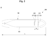
- FIGS. 1 and 2 are respectively a side view and a bottom view of a ship equipped with a frictional resistance reducing device according to a first embodiment of the present disclosure.
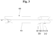
- FIG. 3 is a side view of a ship equipped with a frictional resistance reducing device according to a second embodiment of the present disclosure.
- the ship 10 equipped with the frictional resistance reducing device according to the first embodiment of the present disclosure includes a hull 100 and the frictional resistance reducing device 200.
- the frictional resistance reducing device 200 forms an air layer on a bottom surface 101 of the hull 100 to reduce the frictional resistance of the hull 100.
- the frictional resistance reducing device 200 includes a first air discharge part 210, a second air discharge part 220, and a first air supplying source 230.
- the first air discharge part 210 is formed on the bottom surface 101 of the hull 100.
- the first air discharge part 210 discharges air into water.
- the first air discharge part 210 includes a plurality of air discharge holes 211 and a chamber 212.
- the air discharge holes 211 are distributed in the bottom surface 101 to be spaced apart from each other.
- the air discharge holes 211 may be distributed in a width direction of the hull 100.
- the air supplied from the first air supplying source 230, which will be described later, is discharged into the water through the air discharge holes 211.
- the chamber 212 is disposed inside the hull 100.
- the chamber 212 may be disposed inside the hull 100 to cover the air discharge holes 211.
- the air supplied from the first air supplying source 230 flows into the chamber 212 and is discharged into the water through the air discharge holes 211.
- a chamber 212 constituting a first air discharge part 210' may be disposed outside a hull 100.
- the chamber 212 may be coupled to a bottom surface 101 of the hull 100.
- a plurality of air discharge holes 211 may be formed in side surfaces of the chamber 212, and an inlet for introducing air into the chamber 212 may be formed in the bottom surface 101 of the hull 100.
- various forms of first air discharge parts can be proposed.
- the second air discharge part 220 is formed on the bottom surface 101.
- the second air discharge part 220 discharges air into the water.
- the second air discharge part 220 is located behind the first air discharge part 210, and the first and second air discharge parts 210 and 220 are arranged in a line in a length direction of the hull 100. A reduction in frictional resistance brought about by the discharge of air from the first air discharge part 210 and the second air discharge part 220 arranged in a line will be described later.
- the second air discharge part 220 includes a plurality of air discharge holes 221 and a chamber 222.
- the air discharge holes 221 are distributed in the bottom surface 101 to be spaced apart from each other.
- the air discharge holes 221 may be distributed in the width direction of the hull 100.
- the air supplied from the first air supplying source 230, which will be described later, is discharged into the water through the air discharge holes 221.
- the chamber 222 is disposed inside the hull 100.
- the chamber 222 may be disposed inside the hull 100 to cover the air discharge holes 221.
- the air supplied from the first air supplying source 230 flows into the chamber 222 and is discharged into the water through the air discharge holes 221.
- a chamber 222 constituting a second air discharge part 220' may be disposed outside the hull 100.
- the chamber 222 may be coupled to the bottom surface 101.
- a plurality of air discharge holes 221 may be formed in side surfaces of the chamber 222, and an inlet for introducing air into the chamber 222 may be formed in the bottom surface 101.
- various forms of second air discharge parts can be proposed.
- the first air supplying source 230 supplies air to the first air discharge part 210 or the second air discharge part 220. That is, the first air supplying source 230 may supply air only to the first air discharge part 210, supply air only to the second air discharge part 220, or supply air to both the first and second air discharge parts 210 and 220.
- the first air discharge part 210 and the second air discharge part 220 are illustrated as being supplied with air from one first air supplying source 230. However, the first air discharge part 210 and the second air discharge part 220 can also receive air from different air supplying sources.
- the first air supplying source 230 may be disposed inside the hull 100.
- the first air supplying source 230 may include a compressor or a blower.
- the first air discharge part 210 and the second air discharge part 220 may be arranged closer to a bow than to a stern of the ship 10. Thus, the frictional resistance that can be generated in a traveling direction of the ship 10 can be minimized.
- the first air supplying source 230 may be disposed close to the first air discharge part 210 and the second air discharge part 220. That is, the first air supplying source 230 may also be disposed closer to the bow than to the stern of the ship 10. In this case, an air supply pipe can be made short to facilitate the supply of air.
- At least part of a first air discharge period of the first air discharge part 210 and at least part of a second air discharge period of the second air discharge part 220 may overlap each other. That is, there is a period during which the first air discharge part 210 and the second air discharge part 220 operate simultaneously. Alternatively, the first air discharge part 210 and the second air discharge part 220 may always discharge air simultaneously. The air discharged from the first air discharge part 210 and the second air discharge part 220 forms an air layer on the bottom surface 101 of the hull 100.
- the operating periods of the first air discharge part 210 and the second air discharge part 220 can vary depending on the design. In addition, the operating period of the first air discharge part 210 and the operating period of the second air discharge part 220 can be changed as necessary.
- FIG. 4 illustrates experimental data obtained from a first model ship experiment to show the frictional resistance reducing effect of the frictional resistance reducing device according to the first embodiment of the present disclosure.
- the frictional resistance reducing effect of the frictional resistance reducing device 200 according to the first embodiment of the present disclosure will now be described with reference to FIG. 4 .
- a model ship to which the frictional resistance reducing device 200 according to the first embodiment of the present disclosure was applied was made.
- a first air discharge part discharging air into water and a second air discharge part located behind the first air discharge part and discharging air into the water were formed.
- the resistance of the model ship was measured when air was not discharged at all from the first air discharge part and the second air discharge part (reference case), when air was discharged only from the first air discharge part (CASE 1), when air was discharged only from the second air discharge part (CASE 2), and when air was discharged from both the first air discharge part and the second air discharge part (CASE 3).
- the X-axis represents the experimental case
- the Y-axis represents the resistance reduction rate of the model ship in each experimental case.
- the frictional resistance reduction rate denotes the rate of decrease of the resistance measured in each case with respect to the resistance (hereinafter, referred to as reference resistance) measured in the reference case.
- the resistance reduction rate with respect to the reference resistance was 6.2% in CASE 1, 5.8% in CASE 2, and 9.5% in CASE 3.
- the resistance reduction rate in CASE 3 is higher than that in CASE 1 by 48.38% and higher than that in CASE 2 by 58.62%.
- the frictional resistance reducing device 200 (see FIG. 1 ) according to the first embodiment of the present disclosure is based on the above experimental data and thus effectively reduces frictional resistance by discharging air simultaneously through the first air discharge part 210 and the second air discharge part 220 arranged in a line with one behind the other.
- FIG. 5 illustrates experimental data obtained from a second model ship experiment to show the frictional resistance reducing effect of the frictional resistance reducing device according to the first embodiment of the present disclosure.
- the frictional resistance reducing effect of the frictional resistance reducing device 200 according to the first embodiment of the present disclosure will now be described with reference to FIG. 5 .
- the resistance of the model ship was measured when air was not discharged at all from the first air discharge part and the second air discharge part (reference case) and by varying the amount of air discharged from the second air discharge part while the amount of air discharged from the first air discharge part was kept constant (CASE A, CASE B, CASE C and CASE D).
- the X-axis represents the experimental case
- the Y-axis represents the resistance reduction rate of the model ship in each case.
- the frictional resistance reduction rate denotes the rate of decrease of the resistance measured in each case with respect to the resistance (hereinafter, referred to as reference resistance) measured in the reference case.
- the resistance reduction rate with respect to the reference resistance was 9.6% in CASE A, 10.8% in CASE B, 11.8% in CASE C, and 11% in CASE D.
- CASE C shows the largest resistance reduction rate.
- the second model ship experiment was repeatedly carried out by varying the amount of air discharged from the first air discharge part, and a case showing the largest resistance reduction rate in each round of the second model ship experiment was specified.
- the case showing the largest resistance reduction rate in each round had a commonality in that the amount of air discharged from the first air discharge part was smaller than or equal to the amount of air discharged from the second air discharge part.
- the frictional resistance reducing device 200 ( FIG. 1 ) according to the first embodiment of the present disclosure is based on the above experimental results and thus effectively reduces frictional resistance by making the amount of air discharged from the first air discharge part 210 smaller than or equal to the amount of air discharged from the second air discharge part 220 located behind the first air discharge part 210.
- a distance D between the first air discharge part 210 and the second air discharge part 220 is smaller than or equal to 0.1 times a full length L of the hull 100. That is, 0 ⁇ D ⁇ 0.1L. If the distance D between the first air discharge part 210 and the second air discharge part 220 exceeds 0.1 times the full length L of the hull 100, the frictional resistance reducing effect is significantly reduced.
- a width of each of the first air discharge part 210 and the second air discharge part 220 is smaller than or equal to 0.5 times the width of the hull 100. If the width of each of the first air discharge part 210 and the second air discharge part 220 is greater than 0.5 times the width of the hull 100, the frictional resistance reducing effect is significantly reduced compared to the amount of air discharged. This results in reduced efficiency.
- the width of the first air discharge part 210 is smaller than or equal to the width of the second air discharge part 220. If the width of the first air discharge part 210 is greater than the width of the second air discharge part 220, the frictional resistance reducing effect is significantly reduced compared to the amount of air discharged. This results in reduced efficiency.
- one frictional resistance reducing device 200 according to the first embodiment of the present disclosure is provided.
- this is merely an example, and a plurality of frictional resistance reducing devices can be provided.
- FIG. 6 is a side view of a ship equipped with a frictional resistance reducing device according to a third embodiment of the present disclosure.
- FIG. 7 is a bottom view of the ship equipped with the frictional resistance reducing device according to the third embodiment of the present disclosure.
- FIG. 8 is a side view of a ship equipped with a frictional resistance reducing device according to a fourth embodiment of the present disclosure.
- the following description will focus on differences from FIGS. 1 through 5 .
- the ship 10 includes a hull 100 and the frictional resistance reducing device 200.
- the hull 100 has twin skegs 102a and 102b, that is, a pair of skegs 102a and 102b.
- Propeller shafts (not illustrated) connected to propellers 103a and 103b are rotatably supported inside the twin skegs 102a and 102b, respectively.
- a bottom surface 101 of the hull 100 may be flat.
- a bottom inclined part 105 is formed in the hull100.
- the bottom inclined part 105 is located between the twin skegs 102a and 102b and inclined upward toward a stern.
- the bottom inclined part 105 may extend rearward from a rear end of the flat bottom surface 101.
- the flat bottom surface 101 may extend forward from a front end of the bottom inclined part 105.
- the frictional resistance reducing device 200 reduces the frictional resistance of the hull 100 by forming an air layer on an outer surface of the hull 100.
- the frictional resistance reducing device 200 includes a third air discharge part 1210 and a second air supplying source 1230.
- the third air discharge part 1210 is formed on the bottom surface of the hull 100.
- the third air discharge part 1210 is disposed closer to the stern than to a bow and discharges air between the twin skegs 102a and 102b. More specifically, the third air discharge part 1210 discharges air to the bottom inclined part 105.
- the discharged air forms an air layer on the bottom inclined part 105 to reduce the frictional resistance of the hull 100.
- the third air discharge part 1210 may be disposed in front of a boundary 106 between the bottom surface 101 and the bottom inclined part 105. In other words, the third air discharge part 1210 may be disposed in front of the front end of the bottom inclined part 105.
- the air discharged from the third air discharge part 1210 as the hull 100 advances can easily move to the bottom inclined part 105, and an air layer can be formed from the front end of the bottom inclined part 105.
- the third air discharge part 1210 may be disposed between the boundary 106 (or the rear end of the bottom surface 101) and a position located 1.5 stations forward from the boundary 106 (or the rear end of the bottom surface 101).
- the term 'station' denotes a length obtained by dividing the full length of the hull 100 by 20. If the third air discharge part 1210 is located ahead of the position 1.5 stations away from the boundary 106 (or the rear end of the bottom surface 101), the air discharged from the third air discharge part 1210 cannot easily move to the bottom inclined part 105.
- the third air discharge part 1210 may be disposed at the front end of the bottom inclined part 105.
- the third air discharge part 1210 may be disposed such that a longitudinal centerline C of the hull 100 passes through a widthwise center of the third air discharge part 1210. In this case, the air discharged from the third air discharge part 1210 may be distributed on the bottom inclined part 105 symmetrically with respect to the longitudinal centerline C of the hull 100.
- a width of the third air discharge part 1210 may be smaller than a gap between the twin skegs 102a and 102b.
- the gap between the twin skegs 102a and 102b denotes a gap between central axes of rotation X 1 and X 2 of the propellers 103a and 103b corresponding to the twin skegs 102a and 102b.
- the air discharged from the third air discharge part 1210 can efficiently move to the bottom inclined part 105 located between the twin skegs 102a and 102b and form an air layer.
- the third air discharge part 1210 may include a plurality of air discharge holes 1211 and a chamber 1212.
- the air discharge holes 1211 are distributed in the bottom surface 101 to be spaced apart from each other.
- the air discharge holes 1211 may be distributed in the width direction of the hull 100.
- the air supplied from the second air supplying source 1230, which will be described later, is discharged into water through the air discharge holes 1211.
- the chamber 1212 is disposed inside the hull 100.
- the chamber 1212 may be disposed inside the hull 100 to cover the air discharge holes 1211.
- the air supplied from the second air supplying source 1230 flows into the chamber 1212 and is discharged into the water through the air discharge holes 1211.
- a chamber 1212 constituting a third air discharge part 1210' may be disposed outside a hull 100.
- the chamber 1212 may be coupled to a bottom surface 101.
- a plurality of air discharge holes 1211 may be formed in side surfaces of the chamber 1212, and an inlet for introducing air into the chamber 1212 may be formed in the bottom surface 101.
- various forms of third air discharge parts can be proposed.
- the second air supplying source 1230 supplies air to the third air discharge part 1210.
- the second air supplying source 1230 may be disposed inside the hull 100.
- the second air supplying source 1230 may include a compressor or a blower.
- the hull 100 may include two additional air discharge parts 210 and 220 (the first and second air discharge parts 210 and 210 of FIGS. 1 through 3 ) which discharge air to the bottom surface 101.
- this is merely an example, and one additional air discharge part or three or more additional air discharge parts can be formed.
- At least part of a third air discharge period of the third air discharge part 1210 may overlap at least part of a first air discharge period of the first air discharge part 210 and at least part of a second air discharge period of the second air discharge part 220. That is, there is a period during which the first air discharge part 210, the second air discharge part 220, and the third air discharge part 1210 operate simultaneously. Alternatively, the first air discharge part 210, the second air discharge part 220, and the third air discharge part 1210 may always discharge air simultaneously.
- the operating periods of the first air discharge part 210, the second air discharge part 220 and the third air discharge part 1210 can vary depending on the design. In addition, the operating period of the first air discharge part 210, the operating period of the second air discharge part 220 and the operating period of the third air discharge part 1210 can be changed as necessary.
- the second air supplying source 1230 may also be disposed closer to the stern than to the bow. In this case, an air supply pipe can be made short to facilitate the supply of air.
- a first air supplying source 230 and the second air supplying source 1230 can be spaced apart from each other.
- FIG. 9 is a bottom view of a model ship for explaining the frictional resistance reducing effect of the frictional resistance reducing device according to the third embodiment of the present disclosure.
- FIG. 10 illustrates experimental data for the model ship of FIG. 9 .
- the frictional resistance reducing effect of the frictional resistance reducing device 200 (see FIG. 6 ) according to the current embodiment will now be described with reference to FIGS. 9 and 10 .
- a first air discharge part M210, a second air discharge part M220 and a third air discharge part M1210 are formed on a bottom surface M101 of the model ship M.
- the first air discharge part M210 is formed at a rear end of the bottom surface 101
- the second air discharge part M220 and the third air discharge part M1210 are formed at a front end of the bottom surface.
- the resistance of the model ship was measured when air was not discharged at all (reference case), when air was discharged only from the third air discharge part M1210 (CASE 11), when air was discharged only from the first air discharge part M210 and the second air discharge part M220 (CASE 12), and when air was discharged from all of the first air discharge part M210, the second air discharge part M220 and the third air discharge part M1210 (CASE 13).
- the amount of air discharged in CASE 13 was equal to the sum of the amounts of air discharged in CASE 11 and CASE 12.
- the X-axis represents the experimental case
- the Y-axis represents the resistance reduction rate in each experimental case.
- the frictional resistance reduction rate denotes the rate of decrease of the resistance measured in each case with respect to the resistance (hereinafter, referred to as reference resistance) measured in the reference case.
- the resistance reduction rate with respect to the reference resistance was 3% in CASE 11.
- CASE 11 an air layer was predominantly formed on a bottom inclined part M105 between twin skegs of the model ship M. This air layer reduced the resistance in CASE 11 by 3% from the reference resistance.
- the friction resistance reducing device 200 (see FIG. 6 ) is based on the above experimental data. Therefore, the frictional resistance reducing device 200 forms an air layer on the bottom inclined part 105 (see FIG. 6 ) and the bottom surface 101 (see FIG. 6 ) by discharging air through the third air discharge part 1210 and the additional air discharge parts 210 and 220 located in front of the third air discharge part 1210, thereby effectively reducing the frictional resistance of the ship 10 (see FIG. 6 ) having a twin-skeg hull form.
Landscapes
- Physics & Mathematics (AREA)
- Fluid Mechanics (AREA)
- Chemical & Material Sciences (AREA)
- Engineering & Computer Science (AREA)
- Combustion & Propulsion (AREA)
- Mechanical Engineering (AREA)
- Ocean & Marine Engineering (AREA)
- Braking Arrangements (AREA)
- Aerodynamic Tests, Hydrodynamic Tests, Wind Tunnels, And Water Tanks (AREA)
- General Details Of Gearings (AREA)
Abstract
Description
- The present disclosure relates to a frictional resistance reducing device and a ship including the same.
- An air lubrication system is known as a technology for improving the efficiency of navigation of a ship. The air lubrication system forms an air layer on a bottom surface of a hull by discharging air to an outer surface below a waterline of the hull and reduces the frictional resistance between the ship and water by using the air layer, thereby improving the efficiency of navigation. The technology disclosed in Japanese Laid-Open Patent Publication No.
2009-248831 - Aspects of the present disclosure provide a frictional resistance reducing device which effectively reduces the frictional resistance of a ship.
- Aspects of the present disclosure also provide a ship in which the frictional resistance reducing device is installed.
- According to an aspect of the present disclosure, there is provided a frictional resistance reducing device including: a first air discharge part which is formed on a bottom surface of a hull and discharges air into water; a second air discharge part which is formed behind the first air discharge part and discharges air into the water; and a first air supplying source which supplies air to the first air discharge part or the second air discharge part, wherein the first air discharge part and the second air discharge part are arranged in a line in a length direction of the hull, and at least part of a first air discharge period of the first air discharge part and at least part of a second air discharge period of the second air discharge part overlap each other.
- A distance between the first air discharge part and the second air discharge part is smaller than or equal to 0.1 times a full length of the hull.
- A width of the first air discharge part is smaller than or equal to a width of the second air discharge part.
- The width of each of the first air discharge part and the second air discharge part is smaller than or equal to 0.5 times the width of the hull.
- The amount of air discharged from the first air discharge part is smaller than or equal to the amount of air discharged from the second air discharge part.
- The first air discharge part and the second air discharge part are disposed closer to a bow than to a stern, and the frictional resistance reducing device further includes a third air discharge part which is formed on the bottom of the hull, is disposed closer to the stern than to the bow and discharges air into the water.
- At least part of a third air discharge period of the third air discharge part overlaps at least part of the first air discharge period and at least part of the second air discharge period.
- The hull includes twin skegs, and a width of the third air discharge part is smaller than a gap between the twin skegs.
- The frictional resistance reducing device further includes a second air supplying source which is spaced apart from the first air supplying source and supplies air to the third air discharge part.
- According to another aspect of the present disclosure, there is provided a device for reducing frictional resistance of a hull having twin skegs. The device includes: an air discharge part which discharges air to form an air layer on a bottom inclined part located between the twin skegs and inclined upward toward a stern; and an air supplying source which supplies air to the air discharge part.
- The air discharge part is disposed ahead of a boundary between a bottom surface of the hull and the bottom inclined part.
- The air discharge part is disposed between a position located 1.5 stations forward from the boundary and the boundary.
- The air discharge part is disposed such that a longitudinal centerline of the hull passes through a widthwise center of the air discharge part, and a width of the air discharge part is smaller than a gap between the twin skegs.
- One or more additional air discharge parts which are disposed closer to a bow than to the stern of the hull and discharge air to form an air layer on the bottom surface of the hull are formed.
- The air discharge part and the additional air discharge parts discharge air simultaneously.
- According to another aspect of the present disclosure, there is provided a ship including the frictional resistance reducing device described above.
- A frictional resistance reducing device according to embodiments of the present disclosure can significantly reduce frictional resistance by discharging air through a first air discharge part and a second air discharge part arranged in a line with one behind the other.
- In addition, in a twin-skeg ship, the frictional resistance reducing device can effectively reduce the frictional resistance of the ship having a twin-skeg hull form by forming an air layer on a bottom inclined part between twin skegs.
-
-
FIG. 1 is a side view of a ship equipped with a frictional resistance reducing device according to a first embodiment of the present disclosure; -
FIG. 2 is a bottom view of the ship equipped with the frictional resistance reducing device according to the first embodiment of the present disclosure; -
FIG. 3 is a side view of a ship equipped with a frictional resistance reducing device according to a second embodiment of the present disclosure; -
FIG. 4 illustrates experimental data obtained from a first model ship experiment to show the frictional resistance reducing effect of the frictional resistance reducing device according to the first embodiment of the present disclosure; -
FIG. 5 illustrates experimental data obtained from a second model ship experiment to show the frictional resistance reducing effect of the frictional resistance reducing device according to the first embodiment of the present disclosure; -
FIG. 6 is a side view of a ship equipped with a frictional resistance reducing device according to a third embodiment of the present disclosure; -
FIG. 7 is a bottom view of the ship equipped with the frictional resistance reducing device according to the third embodiment of the present disclosure; -
FIG. 8 is a side view of a ship equipped with a frictional resistance reducing device according to a fourth embodiment of the present disclosure; -
FIG. 9 is a bottom view of a model ship for explaining the frictional resistance reducing effect of the frictional resistance reducing device according to the third embodiment of the present disclosure; and -
FIG. 10 illustrates experimental data for the model ship ofFIG. 9 . - Embodiments according to the present disclosure may be variously modified and may have a variety of forms, and thus, specific embodiments are illustrated in the drawings and described in detail herein or in the present application. However, the following description does not limit the present disclosure to specific embodiments and should be understood to include all variations, equivalents, or substitutions within the spirit and scope of the present disclosure. A detailed description might be omitted when it is determined that related prior art or the detailed description of the structure may unnecessarily obscure the point of the present disclosure.
- Hereinafter, embodiments of the present disclosure will be described in detail with reference to the accompanying drawings. In the following description with reference to the accompanying drawings, the same or corresponding elements will be assigned the same reference numerals, and a redundant description thereof will be omitted.
-
FIGS. 1 and2 are respectively a side view and a bottom view of a ship equipped with a frictional resistance reducing device according to a first embodiment of the present disclosure.FIG. 3 is a side view of a ship equipped with a frictional resistance reducing device according to a second embodiment of the present disclosure. - Referring to
FIGS. 1 and2 , theship 10 equipped with the frictional resistance reducing device according to the first embodiment of the present disclosure includes ahull 100 and the frictionalresistance reducing device 200. - The frictional
resistance reducing device 200 forms an air layer on abottom surface 101 of thehull 100 to reduce the frictional resistance of thehull 100. - The frictional
resistance reducing device 200 includes a firstair discharge part 210, a secondair discharge part 220, and a firstair supplying source 230. - The first
air discharge part 210 is formed on thebottom surface 101 of thehull 100. The firstair discharge part 210 discharges air into water. The firstair discharge part 210 includes a plurality ofair discharge holes 211 and achamber 212. - The
air discharge holes 211 are distributed in thebottom surface 101 to be spaced apart from each other. Theair discharge holes 211 may be distributed in a width direction of thehull 100. The air supplied from the firstair supplying source 230, which will be described later, is discharged into the water through theair discharge holes 211. - The
chamber 212 is disposed inside thehull 100. Thechamber 212 may be disposed inside thehull 100 to cover theair discharge holes 211. The air supplied from the firstair supplying source 230 flows into thechamber 212 and is discharged into the water through theair discharge holes 211. - Alternatively, referring to
FIG. 3 , achamber 212 constituting a first air discharge part 210' may be disposed outside ahull 100. Here, thechamber 212 may be coupled to abottom surface 101 of thehull 100. In this case, a plurality ofair discharge holes 211 may be formed in side surfaces of thechamber 212, and an inlet for introducing air into thechamber 212 may be formed in thebottom surface 101 of thehull 100. In addition, various forms of first air discharge parts can be proposed. - Referring again to
FIGS. 1 and2 , the secondair discharge part 220 is formed on thebottom surface 101. The secondair discharge part 220 discharges air into the water. The secondair discharge part 220 is located behind the firstair discharge part 210, and the first and secondair discharge parts hull 100. A reduction in frictional resistance brought about by the discharge of air from the firstair discharge part 210 and the secondair discharge part 220 arranged in a line will be described later. - The second
air discharge part 220 includes a plurality of air discharge holes 221 and achamber 222. - The air discharge holes 221 are distributed in the
bottom surface 101 to be spaced apart from each other. The air discharge holes 221 may be distributed in the width direction of thehull 100. The air supplied from the firstair supplying source 230, which will be described later, is discharged into the water through the air discharge holes 221. - The
chamber 222 is disposed inside thehull 100. Thechamber 222 may be disposed inside thehull 100 to cover the air discharge holes 221. The air supplied from the firstair supplying source 230 flows into thechamber 222 and is discharged into the water through the air discharge holes 221. - Alternatively, referring to
FIG. 3 , achamber 222 constituting a second air discharge part 220' may be disposed outside thehull 100. Here, thechamber 222 may be coupled to thebottom surface 101. In this case, a plurality of air discharge holes 221 may be formed in side surfaces of thechamber 222, and an inlet for introducing air into thechamber 222 may be formed in thebottom surface 101. In addition, various forms of second air discharge parts can be proposed. - Referring again to
FIGS. 1 and2 , the firstair supplying source 230 supplies air to the firstair discharge part 210 or the secondair discharge part 220. That is, the firstair supplying source 230 may supply air only to the firstair discharge part 210, supply air only to the secondair discharge part 220, or supply air to both the first and secondair discharge parts FIG. 1 , the firstair discharge part 210 and the secondair discharge part 220 are illustrated as being supplied with air from one firstair supplying source 230. However, the firstair discharge part 210 and the secondair discharge part 220 can also receive air from different air supplying sources. The firstair supplying source 230 may be disposed inside thehull 100. The firstair supplying source 230 may include a compressor or a blower. - The first
air discharge part 210 and the secondair discharge part 220 may be arranged closer to a bow than to a stern of theship 10. Thus, the frictional resistance that can be generated in a traveling direction of theship 10 can be minimized. In addition, the firstair supplying source 230 may be disposed close to the firstair discharge part 210 and the secondair discharge part 220. That is, the firstair supplying source 230 may also be disposed closer to the bow than to the stern of theship 10. In this case, an air supply pipe can be made short to facilitate the supply of air. - At least part of a first air discharge period of the first
air discharge part 210 and at least part of a second air discharge period of the secondair discharge part 220 may overlap each other. That is, there is a period during which the firstair discharge part 210 and the secondair discharge part 220 operate simultaneously. Alternatively, the firstair discharge part 210 and the secondair discharge part 220 may always discharge air simultaneously. The air discharged from the firstair discharge part 210 and the secondair discharge part 220 forms an air layer on thebottom surface 101 of thehull 100. The operating periods of the firstair discharge part 210 and the secondair discharge part 220 can vary depending on the design. In addition, the operating period of the firstair discharge part 210 and the operating period of the secondair discharge part 220 can be changed as necessary. - When air is discharged simultaneously from the first
air discharge part 210 and the secondair discharge part 220 arranged in a line with one behind the other, a reduction in frictional resistance is more remarkable than when air is discharged at different times from the firstair discharge part 210 and the secondair discharge part 220. -
FIG. 4 illustrates experimental data obtained from a first model ship experiment to show the frictional resistance reducing effect of the frictional resistance reducing device according to the first embodiment of the present disclosure. The frictional resistance reducing effect of the frictionalresistance reducing device 200 according to the first embodiment of the present disclosure will now be described with reference toFIG. 4 . - For the first model ship experiment, a model ship to which the frictional
resistance reducing device 200 according to the first embodiment of the present disclosure was applied was made. On a bottom surface of the model ship, a first air discharge part discharging air into water and a second air discharge part located behind the first air discharge part and discharging air into the water were formed. - In the first model ship experiment, the resistance of the model ship was measured when air was not discharged at all from the first air discharge part and the second air discharge part (reference case), when air was discharged only from the first air discharge part (CASE 1), when air was discharged only from the second air discharge part (CASE 2), and when air was discharged from both the first air discharge part and the second air discharge part (CASE 3).
- Here, the amount of air discharged in each of
CASE 1,CASE 2 andCASE 3 was the same. - In
FIG. 4 , the X-axis represents the experimental case, and the Y-axis represents the resistance reduction rate of the model ship in each experimental case. Here, the frictional resistance reduction rate denotes the rate of decrease of the resistance measured in each case with respect to the resistance (hereinafter, referred to as reference resistance) measured in the reference case. - Referring to
FIG. 4 , the resistance reduction rate with respect to the reference resistance was 6.2% inCASE 1, 5.8% inCASE 2, and 9.5% inCASE 3. - It can be inferred from these figures that the resistance reduction rate in
CASE 3 is higher than that inCASE 1 by 48.38% and higher than that inCASE 2 by 58.62%. - These results indicate that even if the same amount of air is discharged, the frictional resistance is reduced more significantly when air is discharged simultaneously from the first air discharge part and the second air discharge part arranged in a line with one behind the other than when air is discharged at different times from the first air discharge part and the second air discharge part.
- The frictional resistance reducing device 200 (see
FIG. 1 ) according to the first embodiment of the present disclosure is based on the above experimental data and thus effectively reduces frictional resistance by discharging air simultaneously through the firstair discharge part 210 and the secondair discharge part 220 arranged in a line with one behind the other. -
FIG. 5 illustrates experimental data obtained from a second model ship experiment to show the frictional resistance reducing effect of the frictional resistance reducing device according to the first embodiment of the present disclosure. The frictional resistance reducing effect of the frictionalresistance reducing device 200 according to the first embodiment of the present disclosure will now be described with reference toFIG. 5 . - In the second model ship experiment, the resistance of the model ship was measured when air was not discharged at all from the first air discharge part and the second air discharge part (reference case) and by varying the amount of air discharged from the second air discharge part while the amount of air discharged from the first air discharge part was kept constant (CASE A, CASE B, CASE C and CASE D).
- In
FIG. 5 , the X-axis represents the experimental case, and the Y-axis represents the resistance reduction rate of the model ship in each case. Here, the frictional resistance reduction rate denotes the rate of decrease of the resistance measured in each case with respect to the resistance (hereinafter, referred to as reference resistance) measured in the reference case. - Referring to
FIG. 5 , the resistance reduction rate with respect to the reference resistance was 9.6% in CASE A, 10.8% in CASE B, 11.8% in CASE C, and 11% in CASE D. Here, CASE C shows the largest resistance reduction rate. - The second model ship experiment was repeatedly carried out by varying the amount of air discharged from the first air discharge part, and a case showing the largest resistance reduction rate in each round of the second model ship experiment was specified. The case showing the largest resistance reduction rate in each round had a commonality in that the amount of air discharged from the first air discharge part was smaller than or equal to the amount of air discharged from the second air discharge part.
- The frictional resistance reducing device 200 (
FIG. 1 ) according to the first embodiment of the present disclosure is based on the above experimental results and thus effectively reduces frictional resistance by making the amount of air discharged from the firstair discharge part 210 smaller than or equal to the amount of air discharged from the secondair discharge part 220 located behind the firstair discharge part 210. - A distance D between the first
air discharge part 210 and the secondair discharge part 220 is smaller than or equal to 0.1 times a full length L of thehull 100. That is, 0 < D ≤ 0.1L. If the distance D between the firstair discharge part 210 and the secondair discharge part 220 exceeds 0.1 times the full length L of thehull 100, the frictional resistance reducing effect is significantly reduced. - A width of each of the first
air discharge part 210 and the secondair discharge part 220 is smaller than or equal to 0.5 times the width of thehull 100. If the width of each of the firstair discharge part 210 and the secondair discharge part 220 is greater than 0.5 times the width of thehull 100, the frictional resistance reducing effect is significantly reduced compared to the amount of air discharged. This results in reduced efficiency. - The width of the first
air discharge part 210 is smaller than or equal to the width of the secondair discharge part 220. If the width of the firstair discharge part 210 is greater than the width of the secondair discharge part 220, the frictional resistance reducing effect is significantly reduced compared to the amount of air discharged. This results in reduced efficiency. - In
FIG. 1 , one frictionalresistance reducing device 200 according to the first embodiment of the present disclosure is provided. However, this is merely an example, and a plurality of frictional resistance reducing devices can be provided. -
FIG. 6 is a side view of a ship equipped with a frictional resistance reducing device according to a third embodiment of the present disclosure.FIG. 7 is a bottom view of the ship equipped with the frictional resistance reducing device according to the third embodiment of the present disclosure.FIG. 8 is a side view of a ship equipped with a frictional resistance reducing device according to a fourth embodiment of the present disclosure. For ease of description, the following description will focus on differences fromFIGS. 1 through 5 . - Referring to
FIGS. 6 and7 , theship 10 according to the third embodiment of the present disclosure includes ahull 100 and the frictionalresistance reducing device 200. - The
hull 100 hastwin skegs skegs propellers twin skegs - A
bottom surface 101 of thehull 100 may be flat. - A bottom inclined
part 105 is formed in the hull100. The bottom inclinedpart 105 is located between thetwin skegs part 105 may extend rearward from a rear end of theflat bottom surface 101. In other words, theflat bottom surface 101 may extend forward from a front end of the bottom inclinedpart 105. - The frictional
resistance reducing device 200 reduces the frictional resistance of thehull 100 by forming an air layer on an outer surface of thehull 100. - The frictional
resistance reducing device 200 includes a thirdair discharge part 1210 and a secondair supplying source 1230. - The third
air discharge part 1210 is formed on the bottom surface of thehull 100. The thirdair discharge part 1210 is disposed closer to the stern than to a bow and discharges air between thetwin skegs air discharge part 1210 discharges air to the bottom inclinedpart 105. The discharged air forms an air layer on the bottom inclinedpart 105 to reduce the frictional resistance of thehull 100. - Here, the third
air discharge part 1210 may be disposed in front of aboundary 106 between thebottom surface 101 and the bottom inclinedpart 105. In other words, the thirdair discharge part 1210 may be disposed in front of the front end of the bottom inclinedpart 105. - In this case, the air discharged from the third
air discharge part 1210 as thehull 100 advances can easily move to the bottom inclinedpart 105, and an air layer can be formed from the front end of the bottom inclinedpart 105. - The third
air discharge part 1210 may be disposed between the boundary 106 (or the rear end of the bottom surface 101) and a position located 1.5 stations forward from the boundary 106 (or the rear end of the bottom surface 101). Here, the term 'station' denotes a length obtained by dividing the full length of thehull 100 by 20. If the thirdair discharge part 1210 is located ahead of the position 1.5 stations away from the boundary 106 (or the rear end of the bottom surface 101), the air discharged from the thirdair discharge part 1210 cannot easily move to the bottom inclinedpart 105. - Alternatively, although not illustrated, the third
air discharge part 1210 may be disposed at the front end of the bottom inclinedpart 105. - The third
air discharge part 1210 may be disposed such that a longitudinal centerline C of thehull 100 passes through a widthwise center of the thirdair discharge part 1210. In this case, the air discharged from the thirdair discharge part 1210 may be distributed on the bottom inclinedpart 105 symmetrically with respect to the longitudinal centerline C of thehull 100. - A width of the third
air discharge part 1210 may be smaller than a gap between thetwin skegs twin skegs propellers twin skegs air discharge part 1210 can efficiently move to the bottom inclinedpart 105 located between thetwin skegs - The third
air discharge part 1210 may include a plurality of air discharge holes 1211 and achamber 1212. - The air discharge holes 1211 are distributed in the
bottom surface 101 to be spaced apart from each other. The air discharge holes 1211 may be distributed in the width direction of thehull 100. The air supplied from the secondair supplying source 1230, which will be described later, is discharged into water through the air discharge holes 1211. - The
chamber 1212 is disposed inside thehull 100. Thechamber 1212 may be disposed inside thehull 100 to cover the air discharge holes 1211. The air supplied from the secondair supplying source 1230 flows into thechamber 1212 and is discharged into the water through the air discharge holes 1211. - Alternatively, referring to
FIG. 8 , achamber 1212 constituting a third air discharge part 1210' may be disposed outside ahull 100. Here, thechamber 1212 may be coupled to abottom surface 101. In this case, a plurality of air discharge holes 1211 may be formed in side surfaces of thechamber 1212, and an inlet for introducing air into thechamber 1212 may be formed in thebottom surface 101. In addition, various forms of third air discharge parts can be proposed. - Referring again to
FIGS. 6 and7 , the secondair supplying source 1230 supplies air to the thirdair discharge part 1210. The secondair supplying source 1230 may be disposed inside thehull 100. The secondair supplying source 1230 may include a compressor or a blower. - As illustrated in the drawings, the
hull 100 may include two additionalair discharge parts 210 and 220 (the first and secondair discharge parts FIGS. 1 through 3 ) which discharge air to thebottom surface 101. However, this is merely an example, and one additional air discharge part or three or more additional air discharge parts can be formed. - At least part of a third air discharge period of the third
air discharge part 1210 may overlap at least part of a first air discharge period of the firstair discharge part 210 and at least part of a second air discharge period of the secondair discharge part 220. That is, there is a period during which the firstair discharge part 210, the secondair discharge part 220, and the thirdair discharge part 1210 operate simultaneously. Alternatively, the firstair discharge part 210, the secondair discharge part 220, and the thirdair discharge part 1210 may always discharge air simultaneously. The operating periods of the firstair discharge part 210, the secondair discharge part 220 and the thirdair discharge part 1210 can vary depending on the design. In addition, the operating period of the firstair discharge part 210, the operating period of the secondair discharge part 220 and the operating period of the thirdair discharge part 1210 can be changed as necessary. - In addition, since the third
air discharge part 1210 is disposed closer to the stern than to the bow, the secondair supplying source 1230 may also be disposed closer to the stern than to the bow. In this case, an air supply pipe can be made short to facilitate the supply of air. In addition, since the thirdair discharge part 1210 is disposed close to the stern and the firstair discharge part 210 and the secondair discharge part 220 are disposed close to the bow, a firstair supplying source 230 and the secondair supplying source 1230 can be spaced apart from each other. -
FIG. 9 is a bottom view of a model ship for explaining the frictional resistance reducing effect of the frictional resistance reducing device according to the third embodiment of the present disclosure.FIG. 10 illustrates experimental data for the model ship ofFIG. 9 . The frictional resistance reducing effect of the frictional resistance reducing device 200 (seeFIG. 6 ) according to the current embodiment will now be described with reference toFIGS. 9 and10 . - A first air discharge part M210, a second air discharge part M220 and a third air discharge part M1210 are formed on a bottom surface M101 of the model ship M. The first air discharge part M210 is formed at a rear end of the
bottom surface 101, and the second air discharge part M220 and the third air discharge part M1210 are formed at a front end of the bottom surface. - In the model ship experiment, the resistance of the model ship was measured when air was not discharged at all (reference case), when air was discharged only from the third air discharge part M1210 (CASE 11), when air was discharged only from the first air discharge part M210 and the second air discharge part M220 (CASE 12), and when air was discharged from all of the first air discharge part M210, the second air discharge part M220 and the third air discharge part M1210 (CASE 13).
- Here, the amount of air discharged in
CASE 13 was equal to the sum of the amounts of air discharged inCASE 11 andCASE 12. - In
FIG. 10 , the X-axis represents the experimental case, and the Y-axis represents the resistance reduction rate in each experimental case. Here, the frictional resistance reduction rate denotes the rate of decrease of the resistance measured in each case with respect to the resistance (hereinafter, referred to as reference resistance) measured in the reference case. - Referring to
FIGS. 9 and10 , the resistance reduction rate with respect to the reference resistance was 3% inCASE 11. InCASE 11, an air layer was predominantly formed on a bottom inclined part M105 between twin skegs of the model ship M. This air layer reduced the resistance inCASE 11 by 3% from the reference resistance. - In
CASE 12, the resistance reduction rate with respect to the reference resistance was 7%. - In
CASE 13, the resistance reduction rate with respect to the reference resistance was 11.5%. This figure is higher than 10% which is the sum of the 3% resistance reduction rate inCASE 11 and the 7% resistance reduction rate inCASE 12. - The above results indicate that the resistance reduction rate obtained when air is discharged from the third air discharge part M1210 and the first air discharge part M210 and the second air discharge part M220 located in front of the third air discharge part M1210 is equal to or higher than the resistance reduction rate obtained when air is discharged only from the third air discharge part M1210.
- The friction resistance reducing device 200 (see
FIG. 6 ) is based on the above experimental data. Therefore, the frictionalresistance reducing device 200 forms an air layer on the bottom inclined part 105 (seeFIG. 6 ) and the bottom surface 101 (seeFIG. 6 ) by discharging air through the thirdair discharge part 1210 and the additionalair discharge parts air discharge part 1210, thereby effectively reducing the frictional resistance of the ship 10 (seeFIG. 6 ) having a twin-skeg hull form. - It should be noted that experiments for verifying the frictional resistance reducing effect of the frictional
resistance reducing devices 200 according to the embodiments of the present disclosure can be performed through numerical analysis. - While the present disclosure has been particularly shown and described with reference to exemplary embodiments thereof, it will be understood by those of ordinary skill in the art that various modifications and changes may be made therein through inclusion, alteration, removal or addition of elements without departing from the spirit and scope of the present disclosure as defined by the following claims.
-
- 10: ship
- 100: hull
- 101: bottom surface
- 102a, 102b: skeg
- 105: bottom inclined part
- 200: frictional resistance reducing device
- 210: first air discharge part
- 220: second air discharge part
- 230: air supplying source
- 1210: third air discharge part
Claims (15)
- A frictional resistance reducing device comprising:a first air discharge part which is formed on a bottom surface of a hull and discharges air into water;a second air discharge part which is formed behind the first air discharge part and discharges air into the water; anda first air supplying source which supplies air to the first air discharge part or the second air discharge part,wherein the first air discharge part and the second air discharge part are arranged in a line in a length direction of the hull, and at least part of a first air discharge period of the first air discharge part and at least part of a second air discharge period of the second air discharge part overlap each other.
- The frictional resistance reducing device of claim 1, wherein a distance between the first air discharge part and the second air discharge part is smaller than or equal to 0.1 times a full length of the hull.
- The frictional resistance reducing device of claim 1, wherein a width of the first air discharge part is smaller than or equal to a width of the second air discharge part.
- The frictional resistance reducing device of claim 1, wherein the width of each of the first air discharge part and the second air discharge part is smaller than or equal to 0.5 times the width of the hull.
- The frictional resistance reducing device of claim 1, wherein the amount of air discharged from the first air discharge part is smaller than or equal to the amount of air discharged from the second air discharge part.
- The frictional resistance reducing device of claim 1, wherein the first air discharge part and the second air discharge part are disposed closer to a bow than to a stern and further comprising a third air discharge part which is formed on the bottom of the hull, is disposed closer to the stern than to the bow and discharges air into the water.
- The frictional resistance reducing device of claim 6, wherein at least part of a third air discharge period of the third air discharge part overlaps at least part of the first air discharge period and at least part of the second air discharge period.
- The frictional resistance reducing device of claim 6, wherein the hull comprises twin skegs, and a width of the third air discharge part is smaller than a gap between the twin skegs.
- The frictional resistance reducing device of claim 6, further comprising a second air supplying source which is spaced apart from the first air supplying source and supplies air to the third air discharge part.
- A device for reducing frictional resistance of a hull having twin skegs, the device comprising:an air discharge part which discharges air to form an air layer on a bottom inclined part located between the twin skegs and inclined upward toward a stern; andan air supplying source which supplies air to the air discharge part.
- The device of claim 10, wherein the air discharge part is disposed ahead of a boundary between a bottom surface of the hull and the bottom inclined part.
- The device of claim 10, wherein the air discharge part is disposed between a position located 1.5 stations forward from the boundary and the boundary.
- The device of claim 10, wherein the air discharge part is disposed such that a longitudinal centerline of the hull passes through a widthwise center of the air discharge part, and a width of the air discharge part is smaller than a gap between the twin skegs.
- The device of claim 10, wherein one or more additional air discharge parts which are disposed closer to a bow than to the stern of the hull and discharge air to form an air layer on the bottom surface of the hull are formed.
- A ship comprising:the frictional resistance reducing device of claim 1; anda hull equipped with which the frictional resistance reducing device.
Applications Claiming Priority (3)
| Application Number | Priority Date | Filing Date | Title |
|---|---|---|---|
| KR1020150172180A KR101762755B1 (en) | 2015-12-04 | 2015-12-04 | Frictional resistance reduction device |
| KR1020150172155 | 2015-12-04 | ||
| PCT/KR2016/000200 WO2017094961A1 (en) | 2015-12-04 | 2016-01-08 | Frictional resistance reducing device and ship including same |
Publications (4)
| Publication Number | Publication Date |
|---|---|
| EP3385155A1 true EP3385155A1 (en) | 2018-10-10 |
| EP3385155A4 EP3385155A4 (en) | 2019-06-19 |
| EP3385155B1 EP3385155B1 (en) | 2024-07-17 |
| EP3385155C0 EP3385155C0 (en) | 2024-07-17 |
Family
ID=58797535
Family Applications (1)
| Application Number | Title | Priority Date | Filing Date |
|---|---|---|---|
| EP16870858.4A Active EP3385155B1 (en) | 2015-12-04 | 2016-01-08 | Frictional resistance reducing device and ship including same |
Country Status (6)
| Country | Link |
|---|---|
| US (1) | US10562593B2 (en) |
| EP (1) | EP3385155B1 (en) |
| JP (2) | JP2018535144A (en) |
| CN (1) | CN108290618A (en) |
| SG (1) | SG11201804479SA (en) |
| WO (1) | WO2017094961A1 (en) |
Families Citing this family (2)
| Publication number | Priority date | Publication date | Assignee | Title |
|---|---|---|---|---|
| US10562593B2 (en) | 2015-12-04 | 2020-02-18 | Samsung Heavy Industries Co., Ltd. | Frictional resistance-reducing device and ship including same |
| CN117163211A (en) * | 2023-08-18 | 2023-12-05 | 浙江浙能迈领环境科技有限公司 | A control method and control system for an underwater drag reduction device for a large ship |
Family Cites Families (23)
| Publication number | Priority date | Publication date | Assignee | Title |
|---|---|---|---|---|
| JPS58177790A (en) * | 1982-04-10 | 1983-10-18 | Mitsui Eng & Shipbuild Co Ltd | Ship |
| US5456201A (en) | 1992-01-16 | 1995-10-10 | Bobst; Glen L. | Air bubble lubricated boat hull |
| JPH10175588A (en) * | 1996-12-19 | 1998-06-30 | Ishikawajima Harima Heavy Ind Co Ltd | Ship friction reduction device |
| JP2000025683A (en) | 1998-07-16 | 2000-01-25 | Ishikawajima Harima Heavy Ind Co Ltd | Automatic valve opening control method by RANC of bubbler |
| JP2000128062A (en) | 1998-10-21 | 2000-05-09 | Ishikawajima Harima Heavy Ind Co Ltd | Ship friction reduction device |
| US7096810B1 (en) * | 2005-09-20 | 2006-08-29 | Adams Robert D | Bow mounted vessel propulsion system |
| JP4953294B2 (en) * | 2006-11-02 | 2012-06-13 | 独立行政法人海上技術安全研究所 | Hull frictional resistance reduction device |
| JP5311540B2 (en) | 2008-04-08 | 2013-10-09 | 独立行政法人海上技術安全研究所 | Air bubble entrainment prevention device for ships |
| JP4959667B2 (en) * | 2008-11-21 | 2012-06-27 | 三菱重工業株式会社 | Hull frictional resistance reduction device |
| JP5022344B2 (en) * | 2008-11-21 | 2012-09-12 | 三菱重工業株式会社 | Hull frictional resistance reduction device |
| JP5631039B2 (en) * | 2010-04-01 | 2014-11-26 | 三菱重工業株式会社 | Propeller vibration reduction device |
| JP5606128B2 (en) * | 2010-04-01 | 2014-10-15 | 三菱重工業株式会社 | Ship bubble recovery device |
| JP5334063B2 (en) * | 2010-05-18 | 2013-11-06 | 大宇造船海洋株式会社 | Air cavity ship |
| JP2012001115A (en) * | 2010-06-17 | 2012-01-05 | Ihi Corp | Twin skeg ship |
| JP2012071632A (en) * | 2010-09-27 | 2012-04-12 | Mitsubishi Heavy Ind Ltd | Air lubricating system of ship |
| JP5438667B2 (en) | 2010-12-22 | 2014-03-12 | 三菱電機株式会社 | Microprocessor intermittent error detection method |
| WO2012133625A1 (en) * | 2011-03-31 | 2012-10-04 | 三菱重工業株式会社 | Ship with reduced frictional drag and frictional drag reduction device for ship |
| ES2948082T3 (en) * | 2012-02-21 | 2023-08-30 | Silverstream Tech Bv | Air lubrication system |
| JP2014012443A (en) * | 2012-07-04 | 2014-01-23 | Japan Marine United Corp | Frictional resistance reducing ship |
| US8763547B2 (en) * | 2012-07-25 | 2014-07-01 | Dan Nicolaus Costas | Apparatus for lowering drag on a moving nautical vessel |
| JP6044930B2 (en) * | 2012-11-15 | 2016-12-14 | 国立研究開発法人 海上・港湾・航空技術研究所 | Air blowing device for air lubrication and ship |
| KR20140145775A (en) * | 2013-06-14 | 2014-12-24 | 삼성중공업 주식회사 | Air lubrication apparatus |
| US10562593B2 (en) | 2015-12-04 | 2020-02-18 | Samsung Heavy Industries Co., Ltd. | Frictional resistance-reducing device and ship including same |
-
2016
- 2016-01-08 US US15/780,600 patent/US10562593B2/en active Active
- 2016-01-08 WO PCT/KR2016/000200 patent/WO2017094961A1/en not_active Ceased
- 2016-01-08 JP JP2018527166A patent/JP2018535144A/en active Pending
- 2016-01-08 SG SG11201804479SA patent/SG11201804479SA/en unknown
- 2016-01-08 EP EP16870858.4A patent/EP3385155B1/en active Active
- 2016-01-08 CN CN201680070936.9A patent/CN108290618A/en active Pending
-
2020
- 2020-06-03 JP JP2020096861A patent/JP6935543B2/en active Active
Also Published As
| Publication number | Publication date |
|---|---|
| SG11201804479SA (en) | 2018-06-28 |
| US10562593B2 (en) | 2020-02-18 |
| WO2017094961A1 (en) | 2017-06-08 |
| JP6935543B2 (en) | 2021-09-15 |
| CN108290618A (en) | 2018-07-17 |
| EP3385155A4 (en) | 2019-06-19 |
| JP2020128212A (en) | 2020-08-27 |
| EP3385155B1 (en) | 2024-07-17 |
| JP2018535144A (en) | 2018-11-29 |
| US20180354587A1 (en) | 2018-12-13 |
| EP3385155C0 (en) | 2024-07-17 |
Similar Documents
| Publication | Publication Date | Title |
|---|---|---|
| EP2347951B1 (en) | Device for reducing frictional resistance of ship body | |
| US8991326B2 (en) | Displacement hull form not subject to the limitation of hull speed | |
| EP2058220B1 (en) | Stern shape for displacement type ship | |
| KR101733873B1 (en) | Air lubrication device with opening/closing slit for ships | |
| JP2013002636A (en) | Method of reducing resistance of streamlined body and its application | |
| EP3385155B1 (en) | Frictional resistance reducing device and ship including same | |
| US7192322B2 (en) | Line design and propulsion system for a directionally stable, seagoing boat with rudder propeller drive system | |
| US9162732B2 (en) | Stepped hull | |
| JP5095521B2 (en) | Hull structure | |
| JP2014012443A (en) | Frictional resistance reducing ship | |
| KR101762755B1 (en) | Frictional resistance reduction device | |
| NZ510994A (en) | Thruster with ducts on either sides of vessel contained within surrounding duct | |
| KR20150073901A (en) | Full ship | |
| US20130186318A1 (en) | Vessel | |
| US20120055392A1 (en) | Air lubrication device of ship | |
| KR20150104679A (en) | Propulsive device for ship | |
| KR101911013B1 (en) | twin skeg vessel for improving resistance and thrust | |
| RU2456196C1 (en) | Ducted hull | |
| RU2682373C1 (en) | Method of creating an air layer under the vessel bottom | |
| JP2015231831A (en) | Hull construction | |
| KR20190034173A (en) | Frictional resistance reduction device | |
| RU2682125C1 (en) | Displacement vessel with a device for the formation of air caverns on the bottom | |
| KR20180043237A (en) | Frictional resistance reduction device | |
| KR20140095661A (en) | twin skeg vessel for improving resistance and thrust | |
| KR20130132053A (en) | Ship equipped with tunnel thruster |
Legal Events
| Date | Code | Title | Description |
|---|---|---|---|
| STAA | Information on the status of an ep patent application or granted ep patent |
Free format text: STATUS: THE INTERNATIONAL PUBLICATION HAS BEEN MADE |
|
| PUAI | Public reference made under article 153(3) epc to a published international application that has entered the european phase |
Free format text: ORIGINAL CODE: 0009012 |
|
| STAA | Information on the status of an ep patent application or granted ep patent |
Free format text: STATUS: REQUEST FOR EXAMINATION WAS MADE |
|
| 17P | Request for examination filed |
Effective date: 20180614 |
|
| AK | Designated contracting states |
Kind code of ref document: A1 Designated state(s): AL AT BE BG CH CY CZ DE DK EE ES FI FR GB GR HR HU IE IS IT LI LT LU LV MC MK MT NL NO PL PT RO RS SE SI SK SM TR |
|
| AX | Request for extension of the european patent |
Extension state: BA ME |
|
| DAV | Request for validation of the european patent (deleted) | ||
| DAX | Request for extension of the european patent (deleted) | ||
| A4 | Supplementary search report drawn up and despatched |
Effective date: 20190516 |
|
| RIC1 | Information provided on ipc code assigned before grant |
Ipc: B63B 1/08 20060101ALI20190510BHEP Ipc: B63B 1/38 20060101AFI20190510BHEP |
|
| STAA | Information on the status of an ep patent application or granted ep patent |
Free format text: STATUS: EXAMINATION IS IN PROGRESS |
|
| 17Q | First examination report despatched |
Effective date: 20200324 |
|
| GRAP | Despatch of communication of intention to grant a patent |
Free format text: ORIGINAL CODE: EPIDOSNIGR1 |
|
| STAA | Information on the status of an ep patent application or granted ep patent |
Free format text: STATUS: GRANT OF PATENT IS INTENDED |
|
| INTG | Intention to grant announced |
Effective date: 20240212 |
|
| GRAS | Grant fee paid |
Free format text: ORIGINAL CODE: EPIDOSNIGR3 |
|
| GRAA | (expected) grant |
Free format text: ORIGINAL CODE: 0009210 |
|
| STAA | Information on the status of an ep patent application or granted ep patent |
Free format text: STATUS: THE PATENT HAS BEEN GRANTED |
|
| AK | Designated contracting states |
Kind code of ref document: B1 Designated state(s): AL AT BE BG CH CY CZ DE DK EE ES FI FR GB GR HR HU IE IS IT LI LT LU LV MC MK MT NL NO PL PT RO RS SE SI SK SM TR |
|
| REG | Reference to a national code |
Ref country code: GB Ref legal event code: FG4D |
|
| REG | Reference to a national code |
Ref country code: CH Ref legal event code: EP |
|
| REG | Reference to a national code |
Ref country code: DE Ref legal event code: R096 Ref document number: 602016088482 Country of ref document: DE |
|
| REG | Reference to a national code |
Ref country code: IE Ref legal event code: FG4D |
|
| U01 | Request for unitary effect filed |
Effective date: 20240802 |
|
| U07 | Unitary effect registered |
Designated state(s): AT BE BG DE DK EE FI FR IT LT LU LV MT NL PT SE SI Effective date: 20240820 |
|
| PG25 | Lapsed in a contracting state [announced via postgrant information from national office to epo] |
Ref country code: NO Free format text: LAPSE BECAUSE OF FAILURE TO SUBMIT A TRANSLATION OF THE DESCRIPTION OR TO PAY THE FEE WITHIN THE PRESCRIBED TIME-LIMIT Effective date: 20241017 |
|
| PG25 | Lapsed in a contracting state [announced via postgrant information from national office to epo] |
Ref country code: PL Free format text: LAPSE BECAUSE OF FAILURE TO SUBMIT A TRANSLATION OF THE DESCRIPTION OR TO PAY THE FEE WITHIN THE PRESCRIBED TIME-LIMIT Effective date: 20240717 Ref country code: GR Free format text: LAPSE BECAUSE OF FAILURE TO SUBMIT A TRANSLATION OF THE DESCRIPTION OR TO PAY THE FEE WITHIN THE PRESCRIBED TIME-LIMIT Effective date: 20241018 |
|
| PG25 | Lapsed in a contracting state [announced via postgrant information from national office to epo] |
Ref country code: IS Free format text: LAPSE BECAUSE OF FAILURE TO SUBMIT A TRANSLATION OF THE DESCRIPTION OR TO PAY THE FEE WITHIN THE PRESCRIBED TIME-LIMIT Effective date: 20241117 |
|
| PG25 | Lapsed in a contracting state [announced via postgrant information from national office to epo] |
Ref country code: HR Free format text: LAPSE BECAUSE OF FAILURE TO SUBMIT A TRANSLATION OF THE DESCRIPTION OR TO PAY THE FEE WITHIN THE PRESCRIBED TIME-LIMIT Effective date: 20240717 |
|
| PG25 | Lapsed in a contracting state [announced via postgrant information from national office to epo] |
Ref country code: ES Free format text: LAPSE BECAUSE OF FAILURE TO SUBMIT A TRANSLATION OF THE DESCRIPTION OR TO PAY THE FEE WITHIN THE PRESCRIBED TIME-LIMIT Effective date: 20240717 Ref country code: RS Free format text: LAPSE BECAUSE OF FAILURE TO SUBMIT A TRANSLATION OF THE DESCRIPTION OR TO PAY THE FEE WITHIN THE PRESCRIBED TIME-LIMIT Effective date: 20241017 |
|
| U20 | Renewal fee for the european patent with unitary effect paid |
Year of fee payment: 10 Effective date: 20241220 |
|
| PG25 | Lapsed in a contracting state [announced via postgrant information from national office to epo] |
Ref country code: RS Free format text: LAPSE BECAUSE OF FAILURE TO SUBMIT A TRANSLATION OF THE DESCRIPTION OR TO PAY THE FEE WITHIN THE PRESCRIBED TIME-LIMIT Effective date: 20241017 Ref country code: PL Free format text: LAPSE BECAUSE OF FAILURE TO SUBMIT A TRANSLATION OF THE DESCRIPTION OR TO PAY THE FEE WITHIN THE PRESCRIBED TIME-LIMIT Effective date: 20240717 Ref country code: NO Free format text: LAPSE BECAUSE OF FAILURE TO SUBMIT A TRANSLATION OF THE DESCRIPTION OR TO PAY THE FEE WITHIN THE PRESCRIBED TIME-LIMIT Effective date: 20241017 Ref country code: IS Free format text: LAPSE BECAUSE OF FAILURE TO SUBMIT A TRANSLATION OF THE DESCRIPTION OR TO PAY THE FEE WITHIN THE PRESCRIBED TIME-LIMIT Effective date: 20241117 Ref country code: HR Free format text: LAPSE BECAUSE OF FAILURE TO SUBMIT A TRANSLATION OF THE DESCRIPTION OR TO PAY THE FEE WITHIN THE PRESCRIBED TIME-LIMIT Effective date: 20240717 Ref country code: GR Free format text: LAPSE BECAUSE OF FAILURE TO SUBMIT A TRANSLATION OF THE DESCRIPTION OR TO PAY THE FEE WITHIN THE PRESCRIBED TIME-LIMIT Effective date: 20241018 Ref country code: ES Free format text: LAPSE BECAUSE OF FAILURE TO SUBMIT A TRANSLATION OF THE DESCRIPTION OR TO PAY THE FEE WITHIN THE PRESCRIBED TIME-LIMIT Effective date: 20240717 |
|
| PG25 | Lapsed in a contracting state [announced via postgrant information from national office to epo] |
Ref country code: SM Free format text: LAPSE BECAUSE OF FAILURE TO SUBMIT A TRANSLATION OF THE DESCRIPTION OR TO PAY THE FEE WITHIN THE PRESCRIBED TIME-LIMIT Effective date: 20240717 |
|
| PG25 | Lapsed in a contracting state [announced via postgrant information from national office to epo] |
Ref country code: CZ Free format text: LAPSE BECAUSE OF FAILURE TO SUBMIT A TRANSLATION OF THE DESCRIPTION OR TO PAY THE FEE WITHIN THE PRESCRIBED TIME-LIMIT Effective date: 20240717 |
|
| PG25 | Lapsed in a contracting state [announced via postgrant information from national office to epo] |
Ref country code: SK Free format text: LAPSE BECAUSE OF FAILURE TO SUBMIT A TRANSLATION OF THE DESCRIPTION OR TO PAY THE FEE WITHIN THE PRESCRIBED TIME-LIMIT Effective date: 20240717 |
|
| PLBE | No opposition filed within time limit |
Free format text: ORIGINAL CODE: 0009261 |
|
| STAA | Information on the status of an ep patent application or granted ep patent |
Free format text: STATUS: NO OPPOSITION FILED WITHIN TIME LIMIT |
|
| 26N | No opposition filed |
Effective date: 20250422 |
|
| REG | Reference to a national code |
Ref country code: CH Ref legal event code: PL |
|
| PG25 | Lapsed in a contracting state [announced via postgrant information from national office to epo] |
Ref country code: MC Free format text: LAPSE BECAUSE OF FAILURE TO SUBMIT A TRANSLATION OF THE DESCRIPTION OR TO PAY THE FEE WITHIN THE PRESCRIBED TIME-LIMIT Effective date: 20240717 |
|
| PG25 | Lapsed in a contracting state [announced via postgrant information from national office to epo] |
Ref country code: CH Free format text: LAPSE BECAUSE OF NON-PAYMENT OF DUE FEES Effective date: 20250131 |
|
| PGFP | Annual fee paid to national office [announced via postgrant information from national office to epo] |
Ref country code: GB Payment date: 20251211 Year of fee payment: 11 |
|
| PG25 | Lapsed in a contracting state [announced via postgrant information from national office to epo] |
Ref country code: IE Free format text: LAPSE BECAUSE OF NON-PAYMENT OF DUE FEES Effective date: 20250108 |
|
| U20 | Renewal fee for the european patent with unitary effect paid |
Year of fee payment: 11 Effective date: 20251218 |
|
| PG25 | Lapsed in a contracting state [announced via postgrant information from national office to epo] |
Ref country code: RO Free format text: LAPSE BECAUSE OF FAILURE TO SUBMIT A TRANSLATION OF THE DESCRIPTION OR TO PAY THE FEE WITHIN THE PRESCRIBED TIME-LIMIT Effective date: 20240717 |
|
| PG25 | Lapsed in a contracting state [announced via postgrant information from national office to epo] |
Ref country code: CY Free format text: LAPSE BECAUSE OF FAILURE TO SUBMIT A TRANSLATION OF THE DESCRIPTION OR TO PAY THE FEE WITHIN THE PRESCRIBED TIME-LIMIT Effective date: 20240717 |
|
| PG25 | Lapsed in a contracting state [announced via postgrant information from national office to epo] |
Ref country code: TR Free format text: LAPSE BECAUSE OF FAILURE TO SUBMIT A TRANSLATION OF THE DESCRIPTION OR TO PAY THE FEE WITHIN THE PRESCRIBED TIME-LIMIT Effective date: 20240717 |