EP3385110A1 - Procédé de réglage de la force normale d'une unité de transport d'un moteur linéaire à stator longs - Google Patents
Procédé de réglage de la force normale d'une unité de transport d'un moteur linéaire à stator longs Download PDFInfo
- Publication number
- EP3385110A1 EP3385110A1 EP18161643.4A EP18161643A EP3385110A1 EP 3385110 A1 EP3385110 A1 EP 3385110A1 EP 18161643 A EP18161643 A EP 18161643A EP 3385110 A1 EP3385110 A1 EP 3385110A1
- Authority
- EP
- European Patent Office
- Prior art keywords
- force
- normal force
- transport unit
- transport
- normal
- Prior art date
- Legal status (The legal status is an assumption and is not a legal conclusion. Google has not performed a legal analysis and makes no representation as to the accuracy of the status listed.)
- Granted
Links
- 238000000034 method Methods 0.000 title claims description 10
- 230000005291 magnetic effect Effects 0.000 claims abstract description 43
- 230000001105 regulatory effect Effects 0.000 claims abstract description 19
- 230000033228 biological regulation Effects 0.000 claims description 23
- 230000004907 flux Effects 0.000 claims description 20
- 230000001276 controlling effect Effects 0.000 claims description 12
- 230000032258 transport Effects 0.000 description 319
- 230000001133 acceleration Effects 0.000 description 12
- BGPVFRJUHWVFKM-UHFFFAOYSA-N N1=C2C=CC=CC2=[N+]([O-])C1(CC1)CCC21N=C1C=CC=CC1=[N+]2[O-] Chemical compound N1=C2C=CC=CC2=[N+]([O-])C1(CC1)CCC21N=C1C=CC=CC1=[N+]2[O-] BGPVFRJUHWVFKM-UHFFFAOYSA-N 0.000 description 6
- XEEYBQQBJWHFJM-UHFFFAOYSA-N Iron Chemical group [Fe] XEEYBQQBJWHFJM-UHFFFAOYSA-N 0.000 description 5
- 230000001141 propulsive effect Effects 0.000 description 5
- 238000013461 design Methods 0.000 description 4
- 230000005294 ferromagnetic effect Effects 0.000 description 4
- 238000010276 construction Methods 0.000 description 3
- 230000000694 effects Effects 0.000 description 3
- 238000006243 chemical reaction Methods 0.000 description 2
- 230000006698 induction Effects 0.000 description 2
- 229910052742 iron Inorganic materials 0.000 description 2
- 239000007788 liquid Substances 0.000 description 2
- 238000012423 maintenance Methods 0.000 description 2
- 238000012545 processing Methods 0.000 description 2
- 238000001514 detection method Methods 0.000 description 1
- 230000005284 excitation Effects 0.000 description 1
- 238000002474 experimental method Methods 0.000 description 1
- 239000012530 fluid Substances 0.000 description 1
- 238000009434 installation Methods 0.000 description 1
- 230000010354 integration Effects 0.000 description 1
- 230000003993 interaction Effects 0.000 description 1
- 238000007620 mathematical function Methods 0.000 description 1
- 238000013178 mathematical model Methods 0.000 description 1
- 230000000116 mitigating effect Effects 0.000 description 1
- 238000012544 monitoring process Methods 0.000 description 1
- 238000005457 optimization Methods 0.000 description 1
- 230000008092 positive effect Effects 0.000 description 1
- 230000009467 reduction Effects 0.000 description 1
- 238000004088 simulation Methods 0.000 description 1
- 230000001360 synchronised effect Effects 0.000 description 1
- 230000009466 transformation Effects 0.000 description 1
- 238000004804 winding Methods 0.000 description 1
Images


Classifications
-
- B—PERFORMING OPERATIONS; TRANSPORTING
- B65—CONVEYING; PACKING; STORING; HANDLING THIN OR FILAMENTARY MATERIAL
- B65G—TRANSPORT OR STORAGE DEVICES, e.g. CONVEYORS FOR LOADING OR TIPPING, SHOP CONVEYOR SYSTEMS OR PNEUMATIC TUBE CONVEYORS
- B65G43/00—Control devices, e.g. for safety, warning or fault-correcting
- B65G43/02—Control devices, e.g. for safety, warning or fault-correcting detecting dangerous physical condition of load carriers, e.g. for interrupting the drive in the event of overheating
-
- H—ELECTRICITY
- H02—GENERATION; CONVERSION OR DISTRIBUTION OF ELECTRIC POWER
- H02K—DYNAMO-ELECTRIC MACHINES
- H02K41/00—Propulsion systems in which a rigid body is moved along a path due to dynamo-electric interaction between the body and a magnetic field travelling along the path
- H02K41/02—Linear motors; Sectional motors
-
- H—ELECTRICITY
- H02—GENERATION; CONVERSION OR DISTRIBUTION OF ELECTRIC POWER
- H02P—CONTROL OR REGULATION OF ELECTRIC MOTORS, ELECTRIC GENERATORS OR DYNAMO-ELECTRIC CONVERTERS; CONTROLLING TRANSFORMERS, REACTORS OR CHOKE COILS
- H02P21/00—Arrangements or methods for the control of electric machines by vector control, e.g. by control of field orientation
- H02P21/06—Rotor flux based control involving the use of rotor position or rotor speed sensors
-
- B—PERFORMING OPERATIONS; TRANSPORTING
- B60—VEHICLES IN GENERAL
- B60L—PROPULSION OF ELECTRICALLY-PROPELLED VEHICLES; SUPPLYING ELECTRIC POWER FOR AUXILIARY EQUIPMENT OF ELECTRICALLY-PROPELLED VEHICLES; ELECTRODYNAMIC BRAKE SYSTEMS FOR VEHICLES IN GENERAL; MAGNETIC SUSPENSION OR LEVITATION FOR VEHICLES; MONITORING OPERATING VARIABLES OF ELECTRICALLY-PROPELLED VEHICLES; ELECTRIC SAFETY DEVICES FOR ELECTRICALLY-PROPELLED VEHICLES
- B60L13/00—Electric propulsion for monorail vehicles, suspension vehicles or rack railways; Magnetic suspension or levitation for vehicles
- B60L13/003—Crossings; Points
-
- B—PERFORMING OPERATIONS; TRANSPORTING
- B60—VEHICLES IN GENERAL
- B60L—PROPULSION OF ELECTRICALLY-PROPELLED VEHICLES; SUPPLYING ELECTRIC POWER FOR AUXILIARY EQUIPMENT OF ELECTRICALLY-PROPELLED VEHICLES; ELECTRODYNAMIC BRAKE SYSTEMS FOR VEHICLES IN GENERAL; MAGNETIC SUSPENSION OR LEVITATION FOR VEHICLES; MONITORING OPERATING VARIABLES OF ELECTRICALLY-PROPELLED VEHICLES; ELECTRIC SAFETY DEVICES FOR ELECTRICALLY-PROPELLED VEHICLES
- B60L13/00—Electric propulsion for monorail vehicles, suspension vehicles or rack railways; Magnetic suspension or levitation for vehicles
- B60L13/03—Electric propulsion by linear motors
-
- B—PERFORMING OPERATIONS; TRANSPORTING
- B60—VEHICLES IN GENERAL
- B60L—PROPULSION OF ELECTRICALLY-PROPELLED VEHICLES; SUPPLYING ELECTRIC POWER FOR AUXILIARY EQUIPMENT OF ELECTRICALLY-PROPELLED VEHICLES; ELECTRODYNAMIC BRAKE SYSTEMS FOR VEHICLES IN GENERAL; MAGNETIC SUSPENSION OR LEVITATION FOR VEHICLES; MONITORING OPERATING VARIABLES OF ELECTRICALLY-PROPELLED VEHICLES; ELECTRIC SAFETY DEVICES FOR ELECTRICALLY-PROPELLED VEHICLES
- B60L13/00—Electric propulsion for monorail vehicles, suspension vehicles or rack railways; Magnetic suspension or levitation for vehicles
- B60L13/04—Magnetic suspension or levitation for vehicles
- B60L13/06—Means to sense or control vehicle position or attitude with respect to railway
- B60L13/08—Means to sense or control vehicle position or attitude with respect to railway for the lateral position
-
- B—PERFORMING OPERATIONS; TRANSPORTING
- B65—CONVEYING; PACKING; STORING; HANDLING THIN OR FILAMENTARY MATERIAL
- B65G—TRANSPORT OR STORAGE DEVICES, e.g. CONVEYORS FOR LOADING OR TIPPING, SHOP CONVEYOR SYSTEMS OR PNEUMATIC TUBE CONVEYORS
- B65G54/00—Non-mechanical conveyors not otherwise provided for
- B65G54/02—Non-mechanical conveyors not otherwise provided for electrostatic, electric, or magnetic
-
- H—ELECTRICITY
- H02—GENERATION; CONVERSION OR DISTRIBUTION OF ELECTRIC POWER
- H02P—CONTROL OR REGULATION OF ELECTRIC MOTORS, ELECTRIC GENERATORS OR DYNAMO-ELECTRIC CONVERTERS; CONTROLLING TRANSFORMERS, REACTORS OR CHOKE COILS
- H02P21/00—Arrangements or methods for the control of electric machines by vector control, e.g. by control of field orientation
- H02P21/12—Stator flux based control involving the use of rotor position or rotor speed sensors
-
- H—ELECTRICITY
- H02—GENERATION; CONVERSION OR DISTRIBUTION OF ELECTRIC POWER
- H02P—CONTROL OR REGULATION OF ELECTRIC MOTORS, ELECTRIC GENERATORS OR DYNAMO-ELECTRIC CONVERTERS; CONTROLLING TRANSFORMERS, REACTORS OR CHOKE COILS
- H02P25/00—Arrangements or methods for the control of AC motors characterised by the kind of AC motor or by structural details
- H02P25/02—Arrangements or methods for the control of AC motors characterised by the kind of AC motor or by structural details characterised by the kind of motor
- H02P25/06—Linear motors
- H02P25/062—Linear motors of the induction type
-
- H—ELECTRICITY
- H02—GENERATION; CONVERSION OR DISTRIBUTION OF ELECTRIC POWER
- H02P—CONTROL OR REGULATION OF ELECTRIC MOTORS, ELECTRIC GENERATORS OR DYNAMO-ELECTRIC CONVERTERS; CONTROLLING TRANSFORMERS, REACTORS OR CHOKE COILS
- H02P25/00—Arrangements or methods for the control of AC motors characterised by the kind of AC motor or by structural details
- H02P25/02—Arrangements or methods for the control of AC motors characterised by the kind of AC motor or by structural details characterised by the kind of motor
- H02P25/06—Linear motors
- H02P25/064—Linear motors of the synchronous type
-
- B—PERFORMING OPERATIONS; TRANSPORTING
- B60—VEHICLES IN GENERAL
- B60L—PROPULSION OF ELECTRICALLY-PROPELLED VEHICLES; SUPPLYING ELECTRIC POWER FOR AUXILIARY EQUIPMENT OF ELECTRICALLY-PROPELLED VEHICLES; ELECTRODYNAMIC BRAKE SYSTEMS FOR VEHICLES IN GENERAL; MAGNETIC SUSPENSION OR LEVITATION FOR VEHICLES; MONITORING OPERATING VARIABLES OF ELECTRICALLY-PROPELLED VEHICLES; ELECTRIC SAFETY DEVICES FOR ELECTRICALLY-PROPELLED VEHICLES
- B60L2200/00—Type of vehicles
- B60L2200/26—Rail vehicles
-
- B—PERFORMING OPERATIONS; TRANSPORTING
- B65—CONVEYING; PACKING; STORING; HANDLING THIN OR FILAMENTARY MATERIAL
- B65G—TRANSPORT OR STORAGE DEVICES, e.g. CONVEYORS FOR LOADING OR TIPPING, SHOP CONVEYOR SYSTEMS OR PNEUMATIC TUBE CONVEYORS
- B65G2203/00—Indexing code relating to control or detection of the articles or the load carriers during conveying
- B65G2203/02—Control or detection
-
- H—ELECTRICITY
- H02—GENERATION; CONVERSION OR DISTRIBUTION OF ELECTRIC POWER
- H02P—CONTROL OR REGULATION OF ELECTRIC MOTORS, ELECTRIC GENERATORS OR DYNAMO-ELECTRIC CONVERTERS; CONTROLLING TRANSFORMERS, REACTORS OR CHOKE COILS
- H02P6/00—Arrangements for controlling synchronous motors or other dynamo-electric motors using electronic commutation dependent on the rotor position; Electronic commutators therefor
- H02P6/006—Controlling linear motors
Definitions
- the subject invention relates to a method for controlling a force acting on a transport unit of a transport device in the form of a Langstatorlinearmotors normal force on a stretch of transport predetermined by the transport path to which only on one side of the transport unit drive coils of Langstatorlinearmotors are provided and the transport unit on this side by guide elements is held on the transport route.
- a long-stator linear motor a plurality of electric drive coils forming the stator are arranged adjacent to each other in a stationary manner along a transport path.
- a number of drive magnets either as permanent magnets or as an electrical coil or short-circuit winding, arranged, which cooperate with the drive coils. Due to the interaction of the (electro) magnetic fields of the drive magnets and the drive coils, a driving force acts on the transport unit, which moves the transport unit forward.
- the long stator linear motor can be designed as a synchronous machine, either self-excited or externally excited, or as an asynchronous machine.
- a long-stator linear motor is characterized in particular by a better and more flexible utilization over the entire working range of the movement (position, speed, acceleration), an individual regulation / control of the transport units along the transport route, an improved energy utilization, the reduction of maintenance costs due to the smaller number of wear parts , a simple exchange of transport units, efficient monitoring and fault detection and an optimization of the product flow along the transport route.
- Examples of such long stator linear motors may be the WO 2013/143783 A1 , of the US 6,876,107 B2 , of the US 2013/0074724 A1 or the WO 2004/103792 A1 be removed.
- a normal force can also be generated transversely to the direction of movement.
- the acting drive coil an electric current with a current component in the direction of movement (often referred to as q-component) and a current component in the normal direction (ie transversely to the direction of movement, often called the d-component) are imprinted.
- the current component in the direction of movement is responsible for generating the propulsive force.
- Khong PC, et al., "Magnetic Guidance of the Movers in a Long-Primary Linear Motor," IEEE Transactions on Industry Applications, Vol.47, No.3, May / June 2011, pp. 1319-1327 describe.
- Khong a long stator linear motor is described as seen in the direction of movement, arranged on both sides drive coils and the normal forces on the two sides are used to center the transport unit for guidance in the middle. The regulation of the normal forces is given a lateral deviation of the transport unit from the center of zero.
- the DE 1 963 505 A1 describes a linear induction motor which uses the normal force in the region of a switch to move a transport unit on the switch either along one or the other stretch of section. Also in the area of the switch drive coils are provided on both sides in order to guide the transport unit at the fork of the switch accordingly. The normal force on the switch on one side is reduced or completely eliminated, resulting in a resulting transverse magnetic force. Here, the normal force is thus generated or influenced specifically in the area of the switch in order to control the transport unit at the switch. Along the other sections where again only unilaterally arranged drive coils are provided, but you will again strive for the reasons mentioned above, to avoid a normal force. The same can be said of the EP 3 109 998 A1 be removed.
- a transport unit must also be held securely on the transport route, so that it does not fall down during the movement along the transport route.
- Conceivable here are complex mechanical guides to ensure a secure hold.
- a disadvantage is that such mechanical guides for the worst operating condition (load, speed, acceleration, position of the transport unit, etc.) must be designed.
- the guide and bracket is expensive and oversized in most cases.
- Running forces on the guides also give rise to running noises and the transport units can also run restlessly, which in turn can lead to vibrations and vibrations.
- running noises are very unpleasant, especially when one thinks of large installations with many transport units.
- the drive magnets of the transport unit interact with the iron parts of the stator of the long stator linear motor or the guide construction of the transport path and generate a magnetic force in the normal direction.
- This magnetic force can be regarded as supporting the holding force, but in many cases alone is not sufficient to keep the transport unit safely in all operating conditions on the transport route. Therefore, additional facilities must be provided for guiding and holding the transport unit. This can be additional, not the drive serving permanent magnets or turn additional mechanical guides or brackets. Both makes the transport unit but again consuming.
- the magnetic force is too great, it can mechanically load the transport unit and / or the transport route by high frictional forces due to the resulting high normal force, which can lead to increased wear.
- the normal force is controlled by a controller for regulating the normal force, the controller determines a normal force-forming current component of the drive current cooperating with the transport unit drive coils, so acting on the transport unit resulting normal force as the sum of the normal force, a Magnetic force caused by the drive magnets in the normal direction and an external force acting on the transport unit in the normal direction at least corresponds to a predetermined holding force in the normal direction.
- the normal force which also means a simple control
- the resultant normal force acting on the transport unit can be influenced so that the resulting force acting on the transport unit in terms of magnitude never becomes larger than required and never smaller than necessary.
- the mechanical stress on the guide elements of the transport unit can be reduced and it can also reduce running noise and increase the smoothness of the transport unit.
- a feedforward control in that the regulator for regulating the normal force determines the normal-force-forming current component of the drive current from a known functional relationship between the normal-force-forming current component of the drive current and a nominal variable of the regulation of the normal force.
- a setpoint flux can be specified as a setpoint for regulating the normal force and the normal force-forming current component can be calculated as the quotient of the setpoint flux and a known inductance in the normal direction, which can be implemented very simply.
- control quality can be increased if, in the regulator for regulating the normal force by means of a normal force controller, the normal force-forming current component is determined from the difference between a nominal variable of the regulation of the normal force and an actual variable of the regulation of the normal force.
- the controller for controlling the normal force based on a pilot control of a target value of the control of the normal force a pilot control and determined by means of a normal force controller from the difference of the target size of the control of the normal force and an actual size of the control of the normal force, a regulator current and the normal force-forming current component as the sum of Pre-control current and the regulator current determined.
- a pilot current is determined based on a known relationship of the position of the transport unit relative to the transport path, since this relationship is easily determined.
- the control of the normal force can be easily integrated into a regulation of the movement of the transport unit by a forward force component is determined in a controller for controlling the forward force of the transport unit and a drive current of cooperating with the transport unit drive coils as vectorial sum of the forward force-forming current component and the normal force-forming current component is determined and the drive current to be converted into coil voltages, which are applied to the co-operating with the transport unit drive coils.
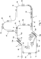
- Fig.1 is a transport device 1 in the form of a Langstatorlinearmotors exemplified.
- the transport device 1 consists of a number of transport segments TSk (k is this an index that stands for all existing transport segments TS1, TS2, TS3, ...), of which for reasons of clarity, for example, only the transport segments TS1 ... TS7 designates are.
- a transport segment TSk is arranged in each case on one side of the transport path.
- the transport segments TSk form different route sections, for example a straight line, curves with different angles and radii, switches, etc., and can be assembled very flexibly in order to form the transport route of the transport device 1.
- the transport segments TSk together thus form the transport route along which the transport units Tn (n is an index which stands for all existing transport units T1, T2, T3, T4,...) Can be moved.
- This modular design allows a very flexible design of the transport device 1.
- the transport segments TSk are of course arranged on a stationary support structure, not shown.
- the workstation S1 can be designed, for example, as a sluice-in and / or outfeed station, in which finished components are removed and components to be processed are transferred to a transport unit Tn.
- any processing steps can be performed on the components.
- the transport units Tn in a workstation S1 ... S4 can also be stopped for processing, for example in a filling station, in which empty bottles are filled, or moved through, for example, in a temperature control in the components are temperature-treated, optionally with another Speed as between workstations S1 ... S4.
- the transport device 1 is designed as a long stator linear motor, in which the transport segments TSk in a conventional manner each form part of a long stator of the long stator linear motor.
- the transport segments TSk are therefore in the longitudinal direction in a known manner a plurality of the stator forming, stationarily arranged electric drive coils 7, 8 are arranged (in Fig.1 for reasons of clarity only for the transport segments TS1, TS2, TS4, TS5, TS6, TS7 indicated), with the drive magnet 4, 5 at the transport units T1 ... Tn (in Fig.1 for reasons of clarity only for the transport unit T6 indicated) can cooperate.
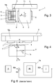
- This is exemplary in the Fig.2 shown in detail.
- a drive magnet 4, 5 can be designed as an electromagnet (excitation coils) and / or as a permanent magnet.
- the drive coils 7, 8 are preferably arranged on teeth 12 of a ferromagnetic core 13 (for example, an iron laminated core).
- the drive coils 7, 8 can also be coreless. Due to this arrangement, it is also immediately apparent that the magnetic flux varies due to the changing magnetic resistance and due to the arrangement of the drive magnet 4, 5 in the longitudinal direction along the transport segment TSk depending on the position of the transport unit Tn.
- transport segments TSk are arranged on both sides, between which a transport unit Tn is moved (for example the transport segments TS1, TS4).
- transport unit Tn is equipped with drive magnets 4, 5 on both sides (viewed in the direction of movement), then the transport unit Tn can also interact simultaneously with the transport segments TSk arranged on both sides.
- a larger propulsion force F Vn can be generated.
- track sections are considered in which only on one side of a transport segments TSk or drive magnets 7, 8 are provided, for example, on the transport segment TS5.
- Figure 3 shows a cross section (transverse to the longitudinal direction) through such a section with a transport segment TSk on one side of the transport path and one on it Moving transport unit Tn.
- a transport unit Tn consists here of a base body 2 and a component receptacle 3 arranged thereon, wherein the component receptacle 3 can in principle be arranged at any point of the base body 2, in particular also on the underside for suspended components.
- the number of drive magnets 4 of the long stator linear motor is arranged on the transport segment TSk side facing the transport unit Tn.
- the transport segment TSk is arranged on a stationary support structure 6 or itself forms part of the stationary support structure 6.
- the drive coils 7, 8 of the long stator linear motor are arranged.
- the transport unit Tn is designed so that the drive magnets 4 are arranged opposite to the drive coils 7, so that the drive magnets 4 can interact with the drive coils 7 to produce a driving force F vn .
- the transport unit Tn along the transport path in the forward direction V is movable.
- guide elements 9 such as rollers, wheels, sliding surfaces, guide magnets, etc.
- the guide elements 9 of the transport unit Tn act to guide with the transport route, for example, the stationary support structure 6 or the transport segments TSk together, for example, in which support the guide elements 9 on the transport route, hook, slide on or unroll, etc.
- an air gap is formed, which is set and maintained, inter alia, by the guide elements 9.
- the drive magnets 4, 5 can also serve as, possibly additional, guide elements 9 in order to keep the transport unit Tn on the transport path.
- the drive magnets 4 cause, for example, a magnetic attraction on the ferromagnetic parts of the guide structure 6 and / or drive coils 7 (for example, an iron core).
- This magnetic force F Mn tries to pull the transport unit Tn in the direction of the transport path and thus causes a holding force in the normal direction N, which also fulfills a holding function when the transport units Tn move.
- the resulting magnetic attraction forces on both sides of the transport unit Tn can cancel of course.
- the guide elements 9 of a transport unit Tn in cooperation with the transport path 15, ensure that the transport unit Tn is held on the transport path 15.
- each transport unit Tn at each point of the Transport route 15 are held securely at the transport path 15 at any time and in any operating condition.
- a minimum holding force in the normal direction N will be necessary to prevent falling of the transport unit Tn from the transport path.
- the guide elements 9 and / or the cooperating components of the guide structure 6 are simple and serve to maintain the air gap and absorb the normal forces acting, as well as to hold a transport unit Tn at least at rest and a drop of the transport unit Tn of the Prevent transport route.
- this holding force will pull the transport unit Tn to the transport path 15.
- "Simply executed” here means in particular that no large forces are generated by these guide elements 9, which burden the mechanical components of the transport path and / or the transport units Tn, for example, by resulting friction, loads in bearings, guides, etc, or too high Run noise.
- an additional external force F En in the normal direction N may act on the transport unit Tn.
- An external force F En in the normal direction N can, for example, in dependence on the position of the transport unit Tn on the transport path (eg slope or inclination of the transport path, curve, etc.) and / or depending on the current operating state of the transport unit Tn (eg speed, acceleration , Load condition, etc.).
- the external force is caused by acceleration forces or centrifugal forces in curves.
- these forces caused by the movement of the transport unit Tn can also be influenced by the mass of the transport unit Tn, and thus, in particular, by the loading of the transport unit Tn.
- a magnetic force F Mn which is produced by the drive magnets 4 in cooperation with the ferromagnetic parts of the drive coils 7 and / or the transport segments TSk and / or the support structure 6 can also act on the transport unit Tn in the normal direction N.
- This magnetic force F Mn pulls the transport unit Tn usually to the transport path 15th
- the resulting normal force P ⁇ Nn acts as a sum of all forces (in the correct sign) in the normal direction N.
- the resulting normal force P ⁇ Nn can try Lift transport unit Tn from the transport path 15 or to the transport line 15 to pull.
- the transport unit Tn could, for example, fall off the transport path 15, which of course must be avoided in any case.
- this resulting normal force P ⁇ Nn must be taken up by the guide elements 9 in any case.
- the guide elements 9 and / or the parts of the transport path 15 cooperating therewith have therefore hitherto been designed so that the transport unit Tn can always be held securely on the transport path 15, whereby the guide elements 9 were greatly oversized in most cases.
- the guide elements 9 and / or the part interacting with them were also heavily loaded (for example by friction), since corresponding forces had to act in the normal direction N.
- the driving force F Vn acts to move them in the forward direction V.
- a magnetic force F Mn which is caused by the drive magnets 4 in cooperation with the ferromagnetic parts of the drive coils 7 and / or the transport segments TSk and / or the support structure 6, optionally acts.
- an external force F En can act on the transport unit Tn.
- These resulting normal force P ⁇ Nn should correspond in magnitude and direction of at least one predetermined holding force F Hnmin , ie F ⁇ Nn ⁇ F Hnmin .
- the vorgebebene holding force F Hmin is the force in the normal direction N, which is needed to keep the transport unit Tn safely on the transport route.
- the normal force F Nn for example, against the direction of the centrifugal force acting as external force F En are generated in order to mitigate or even compensate for the effect of centrifugal forces.
- the effect of a fluctuating fluid can be estimated in planning the transport path 15 (where the type of loading and the movement is planned in advance) and at critical points (eg at places where accelerations act or can act) the required normal force F Nn Mitigating or compensating for the external force F En are generated.
- the applied magnetic force F Mn may be partially canceled by the normal force F Nn to reduce the load on the guide elements 9 by a reduced resultant normal force P ⁇ Nn .
- the mechanical stress on the guide elements 9 and / or on the transport route can be reduced, which also has a positive effect on the service life of the transport unit Tn or on the maintenance intervals.
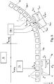
- running noise and vibration of the transport unit Tn can be reduced. This very particularly advantageous application for targeted relief of the guide elements 9, for example, with reference to the Fig. 5 explained.
- a transport path 15 which in the illustrated embodiment consists of two transport segments TSk, TSk + 1, two transport units Tn, Tn + 1 are moved.
- the first transport segment TSk is a straight stretch.
- the transport unit Tn which is here moved at a constant speed vn in the direction of movement V (longitudinal direction of the transport path).
- the transport unit Tn is held by guide elements 9, not shown, on the transport path 15, ie on the transport segment TSk.
- a magnetic force F Mn On the transport unit Tn acts a magnetic force F Mn , which is generated by the drive magnets 4 on the transport unit Tn in cooperation with the transport path 15 (for example, a permanent magnetic attraction).
- a normal force F Nn can be generated in this section, which reduces the magnetic force F Mn to relieve the guide elements 9 and reduce running noise.
- the normal force F Nn is set so that the resulting Normal force P ⁇ Nn (sum of the normal force F Nn and the magnetic force F Mn ) at least the predetermined, required holding force F Hnmin corresponds.
- the following transport segment TSk + 1 is designed as a curve. If a transport unit Tn + 1 at a velocity v n + 1 travels through the curve, acts on the transport unit Tn + 1 as an external force F En + 1, a centrifugal force that tries to lift the transport unit Tn + 1 from the transport segment TSk +. 1
- the normal force F Nn + 1 can now be used here to attenuate the effect of the centrifugal force and thus an effective resulting normal force P ⁇ Nn (sum of the normal force F Nn + 1 , the magnetic force F Mn + 1 and the external force F En + 1 ), which corresponds at least to the predetermined holding force F Hn + 1min .
- the normal force F Nn + 1 could also be used to further attenuate a too high resulting normal force P ⁇ Nn + 1 in the direction of the transport path 15, as long as the predetermined holding force F Hn + 1min is not undershot. Also in this case, the guide elements 9 are relieved and running noise is reduced.
- Each of the transport units Tn can thus be moved individually (position, speed, acceleration) and independently (except for the avoidance of possible collisions) from the other transport units Tn along the transport path 15.
- a transport segment TSk, or the drive coils 7 arranged thereon, can be regulated for this purpose by a segment control unit 11k, such as in FIG Figure 5 described.
- a transport unit Tn which is located in a transport segment TSk, is therefore regulated by the associated segment control unit 11k.
- the segment control unit 11k controls the drive coils 7 of the associated transport segment TSk such that the transport unit Tn thereon is moved by the drive force F Vn in the desired manner (position, speed, acceleration) along the transport segment TSk. It is of course possible that several transport units can be moved simultaneously along a transport segment TSk.
- a transport unit Tn moves from a transport segment TSk to the next transport segment TSk + 1, then the regulation of the Transfers transport unit Tn in an orderly manner to the segment control unit 11k + 1 of the next transport segment TSk + 1.
- the movement of the transport unit Tn by the transport device 1 can be monitored and controlled in a higher-level system control unit 10, which is connected to the segment control units 11k.
- the system control unit 10 controls the movement of the individual transport units Tn by the transport device 1, for example, by position specifications (setpoint values of the control).
- the current position of the transport unit Tn is also detected in a known manner and by the system control unit 10 and / or the segment control unit 11k to hand over.
- the transport path 15 need not be formed by individual transport segments TSk, but it can also be realized a continuous structure.
- segment control unit 11k could be provided, which controls all drive coils 7.
- the segment control units 11k could also be integrated in the system control unit 10.
- drive coils 7, 8 For the movement of the transport unit Tn but not simultaneously arranged on both sides drive coils 7, 8 (if present) must be energized by impressing a stator current i A. It is basically sufficient if the driving force F Vn acting on the transport unit Tn for movement is generated only by means of the drive coils 7 or 8 on one side and the drive magnet 4 or 5 on the associated side of the transport unit Tn. At sections of the transport route where a large propulsion force F Vn is required, eg in the case of a gradient, a heavy load or in areas of acceleration of the transport unit Tn, the drive coils 7, 8 can be energized on both sides (if present) (eg Transport section A9 in Fig.1 ), whereby the driving force F Vn can be increased.
- the guide structure 6 is designed only on one side, or that in certain transport sections, the guide structure 6 is indeed carried out on two sides, but only on one side with drive coils 7, 8 is equipped. That is also in Fig.1 indicated where sections are indicated with double-sided guide structure 6 and sections with only one-sided guide structure 6.
- a target size SGn is the control, for example every 1 ms, for example, a desired position p set and / or a rated speed v Soll, specified for the transport unit Tn.
- a current actual variable IGn for example an actual position p ist and / or an actual speed v ist , of the transport unit Tn is determined.
- the actual size IGn can be measured by means of suitable sensors, can be calculated from other known quantities, for example based on a model of the movement of the transport unit Tn, or can be estimated in an observer.
- the difference between the nominal value SGn and the actual variable IGn is fed to a controller Rk in the corresponding segment control unit 11k, which uses the implemented control law (eg a PI controller or a PID controller) to generate a manipulated variable StGn, for example one at the acting drive coils 7 , 8 to be applied coil voltage u s for energizing the drive coils 7, 8, calculated on the controlled system, here the transport device 1 is set.
- the transport device 1 is set. If a plurality of transport units Tn are simultaneously moved by a transport segment TSk, several controllers Rk, one per transport unit Tn, eg in the associated segment control unit 11k, can also be active independently of one another.
- the regulator Rk is often, but not necessarily, implemented as a regulator cascade, as with reference to FIGS Figure 7 is explained with a position p as a target size SGn.
- the difference between the setpoint quantity SGn and the actual size IGn (actual position) is fed to a position controller RL, which calculates a speed v n of the transport unit Tn to be set as a setpoint variable SGvn for a speed controller RV.
- the difference of this setpoint SGvn and an actual variable IGvn (here an actual speed) is fed to the speed controller RV, which calculates a required driving force-forming current component i Anq of the stator current i A as a setpoint SGin for a current controller RI.
- the difference between the desired value SGin and an actual quantity IGin (here, for example, an actual current) is supplied to the current regulator RI, which calculates a coil voltage u s as the manipulated variable StGn.
- the propulsion force F Vn required for the movement of the transport unit Tn is known to be formed by the propulsive force- forming current component i Anq (q-component) of the stator current i An .
- the non-advancing normal force F Nn is formed by a normal force-forming current component i And (d-component) of the stator current i An .
- the stator current i An is therefore a current vector with a q and a d-component, the d-component has hitherto usually been set to zero or was used only for a point triggering, as in the aforementioned EP 3 109 998 A1 describe.
- the stator current i An corresponds to the vectorial sum current of all the coil currents i s of the drive coils 7 (or 8) of one side acting on the transport unit Tn.
- the propulsion-force-forming current component i Anq thus suffices .
- the propulsion-force-forming current component i Anq corresponds to the vectorial total current of all coil currents i s drive coils 7 (or 8) on one side acting on the transport unit Tn.
- the driving force- forming current component i Anq calculated in the regulator Rk must therefore still be divided between the actually acting drive coils 7. This is due to the known position of the transport unit Tn and the known structure the transport path at any time which drive coils 7 interact with the transport unit Tn.
- the setpoint variable SGin (ie a current) for the current controller RI calculated by the speed controller RV can be divided in a conversion unit 20 into the acting j drive coils 7 (eg by means of the inversely applied inverse transformation), as in FIG Figure 8 shown.
- the divided setpoint variables SGin are then supplied to individual current regulators RI for each of the acting drive coils 7, which then calculate the coil voltages u Sj to be applied to the individual drive coils 7.
- the manipulated variable StGn (the coil voltage u S ) calculated by the current controller RI can first be divided, as in FIG Figure 9 shown.
- the conversion unit 20 can also be separate from the controller Rk.
- the individual coil voltages u Sj of the acting j drive coils 7 can then be applied to the drive coils 7 by the drive coil electronics (not shown).
- the regulation of a transport unit Tn is now extended according to the invention by regulating not only the propulsive force-forming current component i Anq , as hitherto, but also the normal-force-forming current component i And of the stator current i A.
- the goal here is to regulate the resulting normal force P ⁇ Nn (transverse to the driving force F Vn ) acting on the transport unit Tn during operation of the transport device 1 as described above and independently of the advance force F Vn .
- the control of the normal force F Nn is interesting only at sections where only on one side (in the forward direction V seen) of the transport path 15 drive coils 7 (or 8) are arranged (eg A4 in Fig.1 ).
- the external force F En can be determined, for example, by means of suitable sensors.
- an acceleration sensor on the transport unit Tn for example, an acceleration in the normal direction N could be detected, from which a dynamic force as a product of the known mass of the transport unit Tn (including loading) can be calculated with the acceleration in the normal direction N as an external force F En .
- a dynamic force as a product of the known mass of the transport unit Tn including loading
- it can also be a model deposited to the external force F en depending on known To calculate sizes.
- a model could, for example, from a known radius of curvature of the transport path 15 (eg a curve), the speed in the forward direction V and the mass of the transport unit Tn (including loading which can also be assumed to be known) determine a centrifugal force as external force F En .
- the external force F En can also be configured, for example, during the planning of the transport device 1, that is, at certain positions of the transport path 15, a specific external force F En occurring can be assumed, calculated, simulated, etc. and stored at this position.
- the movement of the transport units Tn is normally also planned, with which the external forces F En occurring at certain sections can be estimated and can be stored for the regulation of the normal force F Nn .
- the acting magnetic force F Mn can also be assumed to be known. After the structure of the transport device 1 is known, the magnetic force F Mn can be measured, simulated or calculated, for example.
- the predetermined holding force F Hnmin or equivalent to be set resulting target normal force P ⁇ Nns ⁇ ll can be used as setpoint of the control and the normal force F Nn can be adjusted by a controller Rk to ensure at any time or at each position of the transport path 15 that the resultant normal force P ⁇ Nn corresponds to the predetermined holding force F Hmin , or at least does not fall below this.
- the controller Rk would also need to know the magnetic force F Mn and optionally also the external force F En , which are either fed to the controller Rk or determined in the controller Rk.
- the regulator Rk can also be preset as a nominal value with a desired normal force F Nnsoll which is to be set in order to achieve the predetermined holding force F Hmin .
- the magnetic force F Mn and possibly the external force F En are taken into account in a higher-level unit, for example in the system control unit 10 or a segment control unit 11k.
- a desired normal force F NnSoll can be set, which is sufficient to ensure, at least in one section, that the predetermined holding force F Hmin is maintained.
- the controller Rk can be integrated, for example, in a segment control unit 11k, which is assumed below without limiting the generality. Furthermore, it is assumed in the following that the controller Rk receives a desired normal force F NnSoll as a setpoint.
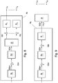
- the controller Rk for controlling the transport unit Tn is now divided into a controller Rq for controlling the driving force F Vn and a controller Rd for regulating the normal force F Nn , as in Figure 10 shown.
- the controller Rq corresponds to a conventional controller of Driving force F Vn , for example, as above with reference to Fig.6 to 9 described.
- the concrete implementation of the regulator Rq plays no role in the regulation of the normal force F Nn according to the invention.
- the system control unit 10 From a higher-level unit, for example, the system control unit 10, as previously a setpoint SGqn for the regulation of the driving force F Vn with the controller Rq and additionally a target value SGdn for the regulation of the normal force F Nn with the controller Rd specified.
- the nominal variable SGdn for the regulation of the normal force F Nn is preferably a desired normal force F NnSoll or, equivalently, a nominal magnetic flux ⁇ ns ⁇ ll in the air gap.
- the calculated driving force-forming current component i Anq and normal-force-forming current component i And are jointly transferred as a current vector of the stator current i An to the current controller RI, which in turn calculates the coil voltages u Sj to be applied.
- the converting unit 20 may be provided before or after the current regulator RI.
- the known relationship f between the desired normal force F Nn-soll or equivalent to the desired magnetic flux ⁇ ns ⁇ ll and the normal force-forming current component i And can be used to the normal force F Nn for a transport unit Tn in a kind of feedforward control control how in Figure 11 shown.
- a desired value for the normal force-forming current component i Andsoll could be set directly.
- the functional relationship f would be given by the unit function. Due to the predetermined and known structure of the transport device 1, the relationship f between the normal force F Nn (or the flow ⁇ ) and the normal force-forming current component i And can be determined in advance (for example calculated, simulated or measured) and can be assumed to be known.
- This relationship f is implemented in the controller Rd, for example as a mathematical function or model.
- a feedback normal force controller RN for example a simple PI or PID controller
- SGdn nominal normal force F NnSoll or nominal magnetic flux oder ns ⁇ ll or also a resulting setpoint normal force P ⁇ Nnsoll
- the actual variable IGdn required for this purpose for example a current magnetic flux ⁇ acting in the air gap, can be measured or in an observer from other measured variables (such as the current coil current and current coil voltage).
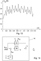
- the magnetic flux ⁇ x acting as a function of the position x of the transport unit Tn relative to the transport path 15 (see FIG Fig. 2 ) over the length of the transport unit Tn (or over the length of the drive magnets 4, 5) are determined in advance.
- this course of the magnetic flux ⁇ x can be measured beforehand (eg by measuring the induction voltage (emf voltage) and integration thereof), simulated (eg in a FEM simulation or by a reluctance network) or can also be estimated by a flux observer.
- An exemplary course of the magnetic flux ⁇ x is in Figure 13 shown.
- This course can be stored, for example in the controller Rk or in the segment control unit 11k, and can be used in the controller Rd, in order to implement a feedforward control for the normal force controller RN.
- Another suitable tax law could be realized, even without the course as in Figure 13 , The controller Rd with feed forward VS could then be as in Figure 14 shown implemented.
- the nominal magnetic flux ⁇ ns ⁇ ll is specified as a setpoint SGdn.
- the desired magnetic flux ⁇ ns ⁇ ll is fed to the precontrol VS, which calculates therefrom a pilot control current i Vs , for example as shown above.
- the actual flow ⁇ nist is estimated in an observer 21 in this exemplary embodiment.
- the control difference between the nominal magnetic flux ⁇ ns ⁇ ll and the actual flow ⁇ nist is supplied to the normal force controller RN, which only has to compensate for small control deviations via the control current i RN .
Landscapes
- Engineering & Computer Science (AREA)
- Power Engineering (AREA)
- Physics & Mathematics (AREA)
- Electromagnetism (AREA)
- Transportation (AREA)
- Mechanical Engineering (AREA)
- Chemical & Material Sciences (AREA)
- Combustion & Propulsion (AREA)
- Non-Mechanical Conveyors (AREA)
- Linear Motors (AREA)
- Control Of Linear Motors (AREA)
Priority Applications (2)
| Application Number | Priority Date | Filing Date | Title |
|---|---|---|---|
| EP21204266.7A EP3978300B1 (fr) | 2017-03-21 | 2018-03-14 | Procédé de réglage de la force normale d'une unité de transport d'un moteur linéaire à stator longs |
| EP22166907.0A EP4049886B1 (fr) | 2017-03-21 | 2018-03-14 | Procédé de réglage de la force normale d'une unité de transport d'un moteur linéaire à stator long |
Applications Claiming Priority (1)
| Application Number | Priority Date | Filing Date | Title |
|---|---|---|---|
| ATA50226/2017A AT519664B1 (de) | 2017-03-21 | 2017-03-21 | Verfahren zur Regelung der Normalkraft einer Transporteinheit eines Langstatorlinearmotors |
Related Child Applications (4)
| Application Number | Title | Priority Date | Filing Date |
|---|---|---|---|
| EP22166907.0A Division EP4049886B1 (fr) | 2017-03-21 | 2018-03-14 | Procédé de réglage de la force normale d'une unité de transport d'un moteur linéaire à stator long |
| EP22166907.0A Division-Into EP4049886B1 (fr) | 2017-03-21 | 2018-03-14 | Procédé de réglage de la force normale d'une unité de transport d'un moteur linéaire à stator long |
| EP21204266.7A Division-Into EP3978300B1 (fr) | 2017-03-21 | 2018-03-14 | Procédé de réglage de la force normale d'une unité de transport d'un moteur linéaire à stator longs |
| EP21204266.7A Division EP3978300B1 (fr) | 2017-03-21 | 2018-03-14 | Procédé de réglage de la force normale d'une unité de transport d'un moteur linéaire à stator longs |
Publications (2)
| Publication Number | Publication Date |
|---|---|
| EP3385110A1 true EP3385110A1 (fr) | 2018-10-10 |
| EP3385110B1 EP3385110B1 (fr) | 2022-10-05 |
Family
ID=61655610
Family Applications (3)
| Application Number | Title | Priority Date | Filing Date |
|---|---|---|---|
| EP22166907.0A Active EP4049886B1 (fr) | 2017-03-21 | 2018-03-14 | Procédé de réglage de la force normale d'une unité de transport d'un moteur linéaire à stator long |
| EP21204266.7A Active EP3978300B1 (fr) | 2017-03-21 | 2018-03-14 | Procédé de réglage de la force normale d'une unité de transport d'un moteur linéaire à stator longs |
| EP18161643.4A Active EP3385110B1 (fr) | 2017-03-21 | 2018-03-14 | Procédé de réglage de la force normale d'une unité de transport d'un moteur linéaire à stator longs |
Family Applications Before (2)
| Application Number | Title | Priority Date | Filing Date |
|---|---|---|---|
| EP22166907.0A Active EP4049886B1 (fr) | 2017-03-21 | 2018-03-14 | Procédé de réglage de la force normale d'une unité de transport d'un moteur linéaire à stator long |
| EP21204266.7A Active EP3978300B1 (fr) | 2017-03-21 | 2018-03-14 | Procédé de réglage de la force normale d'une unité de transport d'un moteur linéaire à stator longs |
Country Status (5)
| Country | Link |
|---|---|
| US (1) | US10246266B2 (fr) |
| EP (3) | EP4049886B1 (fr) |
| CN (1) | CN108631540B (fr) |
| AT (1) | AT519664B1 (fr) |
| CA (1) | CA2998706A1 (fr) |
Cited By (8)
| Publication number | Priority date | Publication date | Assignee | Title |
|---|---|---|---|---|
| EP3569528A1 (fr) * | 2018-05-16 | 2019-11-20 | Schneider Electric Industries SAS | Système de transport |
| WO2020236779A1 (fr) * | 2019-05-21 | 2020-11-26 | Westrock Packaging Systems, Llc | Système de dosage de produit à pas flexible |
| WO2021084081A1 (fr) | 2019-10-31 | 2021-05-06 | B&R Industrial Automation GmbH | Dispositif de transport sous la forme d'un moteur linéaire à stator long |
| WO2021084079A1 (fr) | 2019-10-31 | 2021-05-06 | B&R Industrial Automation GmbH | Dispositif de transport sous la forme d'un moteur linéaire à stator long |
| WO2022049026A1 (fr) | 2020-09-03 | 2022-03-10 | B&R Industrial Automation GmbH | Procédé de fonctionnement d'un moteur linéaire |
| WO2022117524A2 (fr) | 2020-12-01 | 2022-06-09 | B&R Industrial Automation GmbH | Dispositif de transport sous la forme d'un moteur linéaire à stator long |
| WO2023094837A1 (fr) * | 2021-11-29 | 2023-06-01 | ELGAZZAR, Abdulrahman | Systèmes de transport |
| WO2023126356A1 (fr) | 2021-12-27 | 2023-07-06 | B&R Industrial Automation GmbH | Régulation de symétrie de courant |
Families Citing this family (15)
| Publication number | Priority date | Publication date | Assignee | Title |
|---|---|---|---|---|
| FR3063983A1 (fr) * | 2017-03-17 | 2018-09-21 | C.E.R.M.E.X. Constructions Etudes Et Recherches De Materiels Pour L'emballage D'expedition | Dispositif de transfert d'objets |
| AT520088B1 (de) * | 2017-06-29 | 2019-01-15 | B & R Ind Automation Gmbh | Verfahren zum Betreiben einer Transporteinrichtung in Form eines Langstatorlinearmotors |
| EP3489175B1 (fr) * | 2017-11-24 | 2020-02-26 | B&R Industrial Automation GmbH | Dispositif de transport sous forme d'un moteur linéaire à stator long doté d'une section de retournement |
| EP3501878B1 (fr) * | 2017-12-22 | 2022-07-13 | B&R Industrial Automation GmbH | Dispositif de transport sous forme d'un moteur linéaire à stator long |
| WO2020239930A1 (fr) * | 2019-05-28 | 2020-12-03 | B&R Industrial Automation GmbH | Dispositif de transport |
| US11713147B2 (en) | 2019-07-30 | 2023-08-01 | Anheuser-Busch Inbev S.A. | Article picking and treating apparatus |
| CN110950003B (zh) * | 2019-11-26 | 2021-05-14 | 歌尔股份有限公司 | 一种线性传送系统及其控制方法 |
| US11472638B2 (en) * | 2020-02-07 | 2022-10-18 | Canon Kabushiki Kaisha | Conveyance apparatus, production system, and method for manufacturing article |
| CN111806246A (zh) * | 2020-03-20 | 2020-10-23 | 同济大学 | 一种用于磁悬浮列车的悬浮系统控制方法 |
| CN112380670B (zh) * | 2020-10-13 | 2023-08-29 | 中国科学院电工研究所 | 基于虚拟动子的分段供电直线感应电机建模方法、系统 |
| CN112572816A (zh) * | 2020-12-30 | 2021-03-30 | 肖瑞文 | 一种脉冲磁震弹射器 |
| CN113965135B (zh) * | 2021-10-19 | 2023-10-20 | 北京航空航天大学 | 一种直线电机无位置传感器控制系统 |
| CN117021962B (zh) * | 2023-10-07 | 2024-01-19 | 成都尚华电气有限公司 | 一种基于短定子直线电机驱动的列车、系统及控制方法 |
| CN117002267B (zh) * | 2023-10-07 | 2023-12-12 | 西南交通大学 | 一种新型短定子磁浮列车系统及控制方法 |
| CN117200536B (zh) * | 2023-11-07 | 2024-01-16 | 深圳市艾姆克斯科技有限公司 | 一种直线电机及其控制方法 |
Citations (3)
| Publication number | Priority date | Publication date | Assignee | Title |
|---|---|---|---|---|
| DE10241471A1 (de) * | 2002-09-04 | 2004-03-25 | Fachhochschule Jena | Verfahren zur getrennten Steuerung der Vorschubkraft und der Normalkraft eines Induktionsmotors |
| EP2634913A1 (fr) * | 2010-10-26 | 2013-09-04 | Murata Machinery, Ltd. | Système de moteur linéaire réparti |
| EP3109998A1 (fr) * | 2015-06-23 | 2016-12-28 | Bernecker+Rainer Industrie-Elektronik Gesellschaft MbH | Procede et moteur lineaire a stator long destine a transferer une unite de transport a une position de transmission |
Family Cites Families (7)
| Publication number | Priority date | Publication date | Assignee | Title |
|---|---|---|---|---|
| FR1596424A (fr) | 1968-12-26 | 1970-06-15 | ||
| DE4133114C2 (de) * | 1991-10-05 | 1996-11-21 | Michael Rupp | Fördersystem für Stückgut |
| AU2003248622A1 (en) | 2002-06-05 | 2003-12-22 | Jacobs Automation Llc | Controlled motion system |
| WO2004103792A1 (fr) | 2003-05-21 | 2004-12-02 | Schierholz-Translift Schweiz Ag | Ensemble rail, aiguillage et dispositif de transport equipe de capteurs magnetostrictifs |
| US9032880B2 (en) | 2009-01-23 | 2015-05-19 | Magnemotion, Inc. | Transport system powered by short block linear synchronous motors and switching mechanism |
| DE102011113000A1 (de) * | 2011-09-09 | 2013-03-14 | Weiss Gmbh | Transportvorrichtung |
| DE102012204919A1 (de) | 2012-03-27 | 2013-10-02 | Beckhoff Automation Gmbh | Statorvorrichtung für einen linearmotor und lineares transportsystem |
-
2017
- 2017-03-21 AT ATA50226/2017A patent/AT519664B1/de not_active IP Right Cessation
-
2018
- 2018-03-14 EP EP22166907.0A patent/EP4049886B1/fr active Active
- 2018-03-14 EP EP21204266.7A patent/EP3978300B1/fr active Active
- 2018-03-14 EP EP18161643.4A patent/EP3385110B1/fr active Active
- 2018-03-20 US US15/926,334 patent/US10246266B2/en active Active
- 2018-03-21 CN CN201810233538.5A patent/CN108631540B/zh active Active
- 2018-03-21 CA CA2998706A patent/CA2998706A1/fr not_active Abandoned
Patent Citations (3)
| Publication number | Priority date | Publication date | Assignee | Title |
|---|---|---|---|---|
| DE10241471A1 (de) * | 2002-09-04 | 2004-03-25 | Fachhochschule Jena | Verfahren zur getrennten Steuerung der Vorschubkraft und der Normalkraft eines Induktionsmotors |
| EP2634913A1 (fr) * | 2010-10-26 | 2013-09-04 | Murata Machinery, Ltd. | Système de moteur linéaire réparti |
| EP3109998A1 (fr) * | 2015-06-23 | 2016-12-28 | Bernecker+Rainer Industrie-Elektronik Gesellschaft MbH | Procede et moteur lineaire a stator long destine a transferer une unite de transport a une position de transmission |
Cited By (11)
| Publication number | Priority date | Publication date | Assignee | Title |
|---|---|---|---|---|
| EP3569528A1 (fr) * | 2018-05-16 | 2019-11-20 | Schneider Electric Industries SAS | Système de transport |
| EP3569528B1 (fr) | 2018-05-16 | 2020-07-29 | Schneider Electric Industries SAS | Système de transport |
| WO2020236779A1 (fr) * | 2019-05-21 | 2020-11-26 | Westrock Packaging Systems, Llc | Système de dosage de produit à pas flexible |
| US11807462B2 (en) | 2019-05-21 | 2023-11-07 | Westrock Packaging Systems, Llc | Flexible pitch product metering system |
| WO2021084081A1 (fr) | 2019-10-31 | 2021-05-06 | B&R Industrial Automation GmbH | Dispositif de transport sous la forme d'un moteur linéaire à stator long |
| WO2021084079A1 (fr) | 2019-10-31 | 2021-05-06 | B&R Industrial Automation GmbH | Dispositif de transport sous la forme d'un moteur linéaire à stator long |
| WO2022049026A1 (fr) | 2020-09-03 | 2022-03-10 | B&R Industrial Automation GmbH | Procédé de fonctionnement d'un moteur linéaire |
| WO2022117524A2 (fr) | 2020-12-01 | 2022-06-09 | B&R Industrial Automation GmbH | Dispositif de transport sous la forme d'un moteur linéaire à stator long |
| EP4261638A2 (fr) | 2020-12-01 | 2023-10-18 | B&R Industrial Automation GmbH | Dispositif de transport sous forme d'un moteur linéaire à stator long |
| WO2023094837A1 (fr) * | 2021-11-29 | 2023-06-01 | ELGAZZAR, Abdulrahman | Systèmes de transport |
| WO2023126356A1 (fr) | 2021-12-27 | 2023-07-06 | B&R Industrial Automation GmbH | Régulation de symétrie de courant |
Also Published As
| Publication number | Publication date |
|---|---|
| CA2998706A1 (fr) | 2018-09-21 |
| CN108631540B (zh) | 2022-08-19 |
| US20180273304A1 (en) | 2018-09-27 |
| CN108631540A (zh) | 2018-10-09 |
| EP4049886B1 (fr) | 2023-07-19 |
| EP4049886A1 (fr) | 2022-08-31 |
| US10246266B2 (en) | 2019-04-02 |
| EP3385110B1 (fr) | 2022-10-05 |
| AT519664A4 (de) | 2018-09-15 |
| EP3978300A1 (fr) | 2022-04-06 |
| EP3978300B1 (fr) | 2023-03-08 |
| AT519664B1 (de) | 2018-09-15 |
Similar Documents
| Publication | Publication Date | Title |
|---|---|---|
| AT519664B1 (de) | Verfahren zur Regelung der Normalkraft einer Transporteinheit eines Langstatorlinearmotors | |
| EP3422562B1 (fr) | Procédé de fonctionnement d'un dispositif de transport en forme de moteur linéaire à stator long | |
| EP3379719B1 (fr) | Procédé destinés à transferer une unité de transport à une position de transmission | |
| EP3251986B1 (fr) | Procédé de fonctionnement d'un moteur linéaire à stator déployé | |
| DE102014003882B4 (de) | Transportvorrichtung zum Bewegen und/oder Positionieren von Objekten | |
| AT518734B1 (de) | Verfahren zum Betreiben eines Langstatorlinearmotors | |
| WO2008090129A2 (fr) | Procédé et dispositif de commande d'entraînement d'un véhicule à sustentation magnétique sur une ligne ferroviaire à sustentation magnétique | |
| EP3425780B1 (fr) | Dispositif de transport sous forme d'un moteur linéaire à stator long | |
| EP3363751B1 (fr) | Procédé de transfert d'une unité de transport d'un convoyeur à moteur linéaire à une position de transfert | |
| EP3599127B1 (fr) | Procédé de fonctionnement d'un moteur linéaire à stator long pourvu d'unités de transport et surveillance de collision | |
| EP1864370A1 (fr) | Moteur lineaire et procede pour faire fonctionner un moteur lineaire | |
| EP3661033A1 (fr) | Dispositif de transport sous forme d'un moteur linéaire à stator long | |
| EP3575250A1 (fr) | Procédé de commande d'une unité de transport d'un dispositif de transport sous la forme d'un moteur linéaire à stator long | |
| DE2436106A1 (de) | Fahrtechnische einrichtung mit dauermagneten | |
| DE10106233C2 (de) | Linearantrieb für Krane | |
| WO2024047193A1 (fr) | Procédé de commande du mouvement d'un axe d'entraînement d'une unité d'entraînement | |
| WO2023213701A1 (fr) | Procédé et dispositif permettant de surveiller le fonctionnement d'un dispositif de transport | |
| DE2341877A1 (de) | Elektromagnetisches schwebesystem | |
| EP4098473A1 (fr) | Installation de transport et procédé permettant de faire fonctionner une installation de transport ayant une surveillance de collisions |
Legal Events
| Date | Code | Title | Description |
|---|---|---|---|
| PUAI | Public reference made under article 153(3) epc to a published international application that has entered the european phase |
Free format text: ORIGINAL CODE: 0009012 |
|
| STAA | Information on the status of an ep patent application or granted ep patent |
Free format text: STATUS: THE APPLICATION HAS BEEN PUBLISHED |
|
| AK | Designated contracting states |
Kind code of ref document: A1 Designated state(s): AL AT BE BG CH CY CZ DE DK EE ES FI FR GB GR HR HU IE IS IT LI LT LU LV MC MK MT NL NO PL PT RO RS SE SI SK SM TR |
|
| AX | Request for extension of the european patent |
Extension state: BA ME |
|
| STAA | Information on the status of an ep patent application or granted ep patent |
Free format text: STATUS: REQUEST FOR EXAMINATION WAS MADE |
|
| 17P | Request for examination filed |
Effective date: 20190402 |
|
| RBV | Designated contracting states (corrected) |
Designated state(s): AL AT BE BG CH CY CZ DE DK EE ES FI FR GB GR HR HU IE IS IT LI LT LU LV MC MK MT NL NO PL PT RO RS SE SI SK SM TR |
|
| STAA | Information on the status of an ep patent application or granted ep patent |
Free format text: STATUS: EXAMINATION IS IN PROGRESS |
|
| 17Q | First examination report despatched |
Effective date: 20200415 |
|
| STAA | Information on the status of an ep patent application or granted ep patent |
Free format text: STATUS: EXAMINATION IS IN PROGRESS |
|
| GRAP | Despatch of communication of intention to grant a patent |
Free format text: ORIGINAL CODE: EPIDOSNIGR1 |
|
| STAA | Information on the status of an ep patent application or granted ep patent |
Free format text: STATUS: GRANT OF PATENT IS INTENDED |
|
| INTG | Intention to grant announced |
Effective date: 20211109 |
|
| GRAJ | Information related to disapproval of communication of intention to grant by the applicant or resumption of examination proceedings by the epo deleted |
Free format text: ORIGINAL CODE: EPIDOSDIGR1 |
|
| STAA | Information on the status of an ep patent application or granted ep patent |
Free format text: STATUS: EXAMINATION IS IN PROGRESS |
|
| INTC | Intention to grant announced (deleted) | ||
| GRAP | Despatch of communication of intention to grant a patent |
Free format text: ORIGINAL CODE: EPIDOSNIGR1 |
|
| STAA | Information on the status of an ep patent application or granted ep patent |
Free format text: STATUS: GRANT OF PATENT IS INTENDED |
|
| INTG | Intention to grant announced |
Effective date: 20220412 |
|
| INTG | Intention to grant announced |
Effective date: 20220502 |
|
| GRAS | Grant fee paid |
Free format text: ORIGINAL CODE: EPIDOSNIGR3 |
|
| GRAA | (expected) grant |
Free format text: ORIGINAL CODE: 0009210 |
|
| STAA | Information on the status of an ep patent application or granted ep patent |
Free format text: STATUS: THE PATENT HAS BEEN GRANTED |
|
| AK | Designated contracting states |
Kind code of ref document: B1 Designated state(s): AL AT BE BG CH CY CZ DE DK EE ES FI FR GB GR HR HU IE IS IT LI LT LU LV MC MK MT NL NO PL PT RO RS SE SI SK SM TR |
|
| REG | Reference to a national code |
Ref country code: GB Ref legal event code: FG4D Free format text: NOT ENGLISH |
|
| REG | Reference to a national code |
Ref country code: CH Ref legal event code: EP |
|
| REG | Reference to a national code |
Ref country code: AT Ref legal event code: REF Ref document number: 1522555 Country of ref document: AT Kind code of ref document: T Effective date: 20221015 |
|
| REG | Reference to a national code |
Ref country code: IE Ref legal event code: FG4D Free format text: LANGUAGE OF EP DOCUMENT: GERMAN |
|
| REG | Reference to a national code |
Ref country code: DE Ref legal event code: R096 Ref document number: 502018010749 Country of ref document: DE |
|
| REG | Reference to a national code |
Ref country code: LT Ref legal event code: MG9D |
|
| REG | Reference to a national code |
Ref country code: NL Ref legal event code: MP Effective date: 20221005 |
|
| PG25 | Lapsed in a contracting state [announced via postgrant information from national office to epo] |
Ref country code: NL Free format text: LAPSE BECAUSE OF FAILURE TO SUBMIT A TRANSLATION OF THE DESCRIPTION OR TO PAY THE FEE WITHIN THE PRESCRIBED TIME-LIMIT Effective date: 20221005 |
|
| PG25 | Lapsed in a contracting state [announced via postgrant information from national office to epo] |
Ref country code: SE Free format text: LAPSE BECAUSE OF FAILURE TO SUBMIT A TRANSLATION OF THE DESCRIPTION OR TO PAY THE FEE WITHIN THE PRESCRIBED TIME-LIMIT Effective date: 20221005 Ref country code: PT Free format text: LAPSE BECAUSE OF FAILURE TO SUBMIT A TRANSLATION OF THE DESCRIPTION OR TO PAY THE FEE WITHIN THE PRESCRIBED TIME-LIMIT Effective date: 20230206 Ref country code: NO Free format text: LAPSE BECAUSE OF FAILURE TO SUBMIT A TRANSLATION OF THE DESCRIPTION OR TO PAY THE FEE WITHIN THE PRESCRIBED TIME-LIMIT Effective date: 20230105 Ref country code: LT Free format text: LAPSE BECAUSE OF FAILURE TO SUBMIT A TRANSLATION OF THE DESCRIPTION OR TO PAY THE FEE WITHIN THE PRESCRIBED TIME-LIMIT Effective date: 20221005 Ref country code: FI Free format text: LAPSE BECAUSE OF FAILURE TO SUBMIT A TRANSLATION OF THE DESCRIPTION OR TO PAY THE FEE WITHIN THE PRESCRIBED TIME-LIMIT Effective date: 20221005 Ref country code: ES Free format text: LAPSE BECAUSE OF FAILURE TO SUBMIT A TRANSLATION OF THE DESCRIPTION OR TO PAY THE FEE WITHIN THE PRESCRIBED TIME-LIMIT Effective date: 20221005 |
|
| PGFP | Annual fee paid to national office [announced via postgrant information from national office to epo] |
Ref country code: FR Payment date: 20230302 Year of fee payment: 6 |
|
| PG25 | Lapsed in a contracting state [announced via postgrant information from national office to epo] |
Ref country code: RS Free format text: LAPSE BECAUSE OF FAILURE TO SUBMIT A TRANSLATION OF THE DESCRIPTION OR TO PAY THE FEE WITHIN THE PRESCRIBED TIME-LIMIT Effective date: 20221005 Ref country code: PL Free format text: LAPSE BECAUSE OF FAILURE TO SUBMIT A TRANSLATION OF THE DESCRIPTION OR TO PAY THE FEE WITHIN THE PRESCRIBED TIME-LIMIT Effective date: 20221005 Ref country code: LV Free format text: LAPSE BECAUSE OF FAILURE TO SUBMIT A TRANSLATION OF THE DESCRIPTION OR TO PAY THE FEE WITHIN THE PRESCRIBED TIME-LIMIT Effective date: 20221005 Ref country code: IS Free format text: LAPSE BECAUSE OF FAILURE TO SUBMIT A TRANSLATION OF THE DESCRIPTION OR TO PAY THE FEE WITHIN THE PRESCRIBED TIME-LIMIT Effective date: 20230205 Ref country code: HR Free format text: LAPSE BECAUSE OF FAILURE TO SUBMIT A TRANSLATION OF THE DESCRIPTION OR TO PAY THE FEE WITHIN THE PRESCRIBED TIME-LIMIT Effective date: 20221005 Ref country code: GR Free format text: LAPSE BECAUSE OF FAILURE TO SUBMIT A TRANSLATION OF THE DESCRIPTION OR TO PAY THE FEE WITHIN THE PRESCRIBED TIME-LIMIT Effective date: 20230106 |
|
| PGFP | Annual fee paid to national office [announced via postgrant information from national office to epo] |
Ref country code: IT Payment date: 20230222 Year of fee payment: 6 |
|
| REG | Reference to a national code |
Ref country code: DE Ref legal event code: R097 Ref document number: 502018010749 Country of ref document: DE |
|
| P01 | Opt-out of the competence of the unified patent court (upc) registered |
Effective date: 20230615 |
|
| PG25 | Lapsed in a contracting state [announced via postgrant information from national office to epo] |
Ref country code: SM Free format text: LAPSE BECAUSE OF FAILURE TO SUBMIT A TRANSLATION OF THE DESCRIPTION OR TO PAY THE FEE WITHIN THE PRESCRIBED TIME-LIMIT Effective date: 20221005 Ref country code: RO Free format text: LAPSE BECAUSE OF FAILURE TO SUBMIT A TRANSLATION OF THE DESCRIPTION OR TO PAY THE FEE WITHIN THE PRESCRIBED TIME-LIMIT Effective date: 20221005 Ref country code: EE Free format text: LAPSE BECAUSE OF FAILURE TO SUBMIT A TRANSLATION OF THE DESCRIPTION OR TO PAY THE FEE WITHIN THE PRESCRIBED TIME-LIMIT Effective date: 20221005 Ref country code: DK Free format text: LAPSE BECAUSE OF FAILURE TO SUBMIT A TRANSLATION OF THE DESCRIPTION OR TO PAY THE FEE WITHIN THE PRESCRIBED TIME-LIMIT Effective date: 20221005 Ref country code: CZ Free format text: LAPSE BECAUSE OF FAILURE TO SUBMIT A TRANSLATION OF THE DESCRIPTION OR TO PAY THE FEE WITHIN THE PRESCRIBED TIME-LIMIT Effective date: 20221005 |
|
| PLBE | No opposition filed within time limit |
Free format text: ORIGINAL CODE: 0009261 |
|
| STAA | Information on the status of an ep patent application or granted ep patent |
Free format text: STATUS: NO OPPOSITION FILED WITHIN TIME LIMIT |
|
| PG25 | Lapsed in a contracting state [announced via postgrant information from national office to epo] |
Ref country code: SK Free format text: LAPSE BECAUSE OF FAILURE TO SUBMIT A TRANSLATION OF THE DESCRIPTION OR TO PAY THE FEE WITHIN THE PRESCRIBED TIME-LIMIT Effective date: 20221005 Ref country code: AL Free format text: LAPSE BECAUSE OF FAILURE TO SUBMIT A TRANSLATION OF THE DESCRIPTION OR TO PAY THE FEE WITHIN THE PRESCRIBED TIME-LIMIT Effective date: 20221005 |
|
| 26N | No opposition filed |
Effective date: 20230706 |
|
| PG25 | Lapsed in a contracting state [announced via postgrant information from national office to epo] |
Ref country code: MC Free format text: LAPSE BECAUSE OF FAILURE TO SUBMIT A TRANSLATION OF THE DESCRIPTION OR TO PAY THE FEE WITHIN THE PRESCRIBED TIME-LIMIT Effective date: 20221005 |
|
| REG | Reference to a national code |
Ref country code: CH Ref legal event code: PL |
|
| GBPC | Gb: european patent ceased through non-payment of renewal fee |
Effective date: 20230314 |
|
| PG25 | Lapsed in a contracting state [announced via postgrant information from national office to epo] |
Ref country code: SI Free format text: LAPSE BECAUSE OF FAILURE TO SUBMIT A TRANSLATION OF THE DESCRIPTION OR TO PAY THE FEE WITHIN THE PRESCRIBED TIME-LIMIT Effective date: 20221005 |
|
| REG | Reference to a national code |
Ref country code: BE Ref legal event code: MM Effective date: 20230331 |
|
| PG25 | Lapsed in a contracting state [announced via postgrant information from national office to epo] |
Ref country code: LU Free format text: LAPSE BECAUSE OF NON-PAYMENT OF DUE FEES Effective date: 20230314 |
|
| REG | Reference to a national code |
Ref country code: IE Ref legal event code: MM4A |
|
| PG25 | Lapsed in a contracting state [announced via postgrant information from national office to epo] |
Ref country code: GB Free format text: LAPSE BECAUSE OF NON-PAYMENT OF DUE FEES Effective date: 20230314 |
|
| PG25 | Lapsed in a contracting state [announced via postgrant information from national office to epo] |
Ref country code: LI Free format text: LAPSE BECAUSE OF NON-PAYMENT OF DUE FEES Effective date: 20230331 Ref country code: IE Free format text: LAPSE BECAUSE OF NON-PAYMENT OF DUE FEES Effective date: 20230314 Ref country code: GB Free format text: LAPSE BECAUSE OF NON-PAYMENT OF DUE FEES Effective date: 20230314 Ref country code: CH Free format text: LAPSE BECAUSE OF NON-PAYMENT OF DUE FEES Effective date: 20230331 |
|
| PG25 | Lapsed in a contracting state [announced via postgrant information from national office to epo] |
Ref country code: BE Free format text: LAPSE BECAUSE OF NON-PAYMENT OF DUE FEES Effective date: 20230331 |
|
| PGFP | Annual fee paid to national office [announced via postgrant information from national office to epo] |
Ref country code: DE Payment date: 20240129 Year of fee payment: 7 |
|
| REG | Reference to a national code |
Ref country code: AT Ref legal event code: MM01 Ref document number: 1522555 Country of ref document: AT Kind code of ref document: T Effective date: 20230314 |