EP3384366B1 - Procédés et appareil de navigation dans des environnements de réalité virtuelle - Google Patents
Procédés et appareil de navigation dans des environnements de réalité virtuelle Download PDFInfo
- Publication number
- EP3384366B1 EP3384366B1 EP16828853.8A EP16828853A EP3384366B1 EP 3384366 B1 EP3384366 B1 EP 3384366B1 EP 16828853 A EP16828853 A EP 16828853A EP 3384366 B1 EP3384366 B1 EP 3384366B1
- Authority
- EP
- European Patent Office
- Prior art keywords
- location
- reachable
- virtual
- unreachable
- physical
- Prior art date
- Legal status (The legal status is an assumption and is not a legal conclusion. Google has not performed a legal analysis and makes no representation as to the accuracy of the status listed.)
- Active
Links
Images



Classifications
-
- G—PHYSICS
- G06—COMPUTING OR CALCULATING; COUNTING
- G06T—IMAGE DATA PROCESSING OR GENERATION, IN GENERAL
- G06T19/00—Manipulating three-dimensional [3D] models or images for computer graphics
- G06T19/003—Navigation within 3D models or images
-
- G—PHYSICS
- G06—COMPUTING OR CALCULATING; COUNTING
- G06F—ELECTRIC DIGITAL DATA PROCESSING
- G06F3/00—Input arrangements for transferring data to be processed into a form capable of being handled by the computer; Output arrangements for transferring data from processing unit to output unit, e.g. interface arrangements
- G06F3/01—Input arrangements or combined input and output arrangements for interaction between user and computer
- G06F3/017—Gesture based interaction, e.g. based on a set of recognized hand gestures
-
- G—PHYSICS
- G02—OPTICS
- G02B—OPTICAL ELEMENTS, SYSTEMS OR APPARATUS
- G02B27/00—Optical systems or apparatus not provided for by any of the groups G02B1/00 - G02B26/00, G02B30/00
- G02B27/01—Head-up displays
- G02B27/017—Head mounted
-
- G—PHYSICS
- G06—COMPUTING OR CALCULATING; COUNTING
- G06F—ELECTRIC DIGITAL DATA PROCESSING
- G06F3/00—Input arrangements for transferring data to be processed into a form capable of being handled by the computer; Output arrangements for transferring data from processing unit to output unit, e.g. interface arrangements
- G06F3/01—Input arrangements or combined input and output arrangements for interaction between user and computer
- G06F3/011—Arrangements for interaction with the human body, e.g. for user immersion in virtual reality
-
- G—PHYSICS
- G06—COMPUTING OR CALCULATING; COUNTING
- G06F—ELECTRIC DIGITAL DATA PROCESSING
- G06F3/00—Input arrangements for transferring data to be processed into a form capable of being handled by the computer; Output arrangements for transferring data from processing unit to output unit, e.g. interface arrangements
- G06F3/01—Input arrangements or combined input and output arrangements for interaction between user and computer
- G06F3/048—Interaction techniques based on graphical user interfaces [GUI]
- G06F3/0481—Interaction techniques based on graphical user interfaces [GUI] based on specific properties of the displayed interaction object or a metaphor-based environment, e.g. interaction with desktop elements like windows or icons, or assisted by a cursor's changing behaviour or appearance
- G06F3/04815—Interaction with a metaphor-based environment or interaction object displayed as three-dimensional [3D], e.g. changing the user viewpoint with respect to the environment or object
-
- G—PHYSICS
- G06—COMPUTING OR CALCULATING; COUNTING
- G06F—ELECTRIC DIGITAL DATA PROCESSING
- G06F3/00—Input arrangements for transferring data to be processed into a form capable of being handled by the computer; Output arrangements for transferring data from processing unit to output unit, e.g. interface arrangements
- G06F3/01—Input arrangements or combined input and output arrangements for interaction between user and computer
- G06F3/048—Interaction techniques based on graphical user interfaces [GUI]
- G06F3/0484—Interaction techniques based on graphical user interfaces [GUI] for the control of specific functions or operations, e.g. selecting or manipulating an object, an image or a displayed text element, setting a parameter value or selecting a range
-
- G—PHYSICS
- G06—COMPUTING OR CALCULATING; COUNTING
- G06T—IMAGE DATA PROCESSING OR GENERATION, IN GENERAL
- G06T19/00—Manipulating three-dimensional [3D] models or images for computer graphics
- G06T19/006—Mixed reality
-
- G—PHYSICS
- G06—COMPUTING OR CALCULATING; COUNTING
- G06T—IMAGE DATA PROCESSING OR GENERATION, IN GENERAL
- G06T19/00—Manipulating three-dimensional [3D] models or images for computer graphics
- G06T19/20—Editing of three-dimensional [3D] images, e.g. changing shapes or colours, aligning objects or positioning parts
Definitions
- This disclosure relates generally to virtual reality (VR), and, more particularly, to methods and apparatus to navigate within VR environments.
- VR virtual reality
- VR environments use sensors, cameras, etc. to detect where a person is located and how the person moves within a VR environment.
- the location and movement information can be used to determine when a person reaches and/or interacts with an object in the VR environment.
- US2016/098094 A1 (MINKKINEN SAMI [FI], 2016-04-07) teaches a method and system where a user can imitate a tap gesture with a fingertip in space without a physical surface to tap on and, if the trajectory of the fingertip is tracked in the course of movement, the tap gesture is performed by a 3D reversal, wherein in a 3D reversal, the trajectory becomes substantially reversed.
- a disclosed example method includes defining a reachable portion of a virtual-reality (VR) environment, defining an unreachable portion of the VR environment separate from the reachable portion, and translating a physical hand location in the reachable portion into a virtual hand location in the unreachable portion.
- VR virtual-reality
- a disclosed examples apparatus includes a reachable sensor to sense a physical hand location, and a processor programmed to: define a reachable portion of a virtual-reality (VR) environment, define an unreachable portion of the VR environment beyond the reachable portion, and translate the sensed physical hand location in the reachable portion into a virtual hand location in the unreachable portion.
- VR virtual-reality
- a disclosed example non-transitory machine-readable media stores machine-readable instructions that, when executed, cause a machine to at least define a reachable portion of a virtual-reality (VR) environment, define an unreachable portion of the VR environment, and translate a physical hand location in the reachable portion into a virtual hand location in the unreachable portion.
- VR virtual-reality
- VR content creators prefer not to have to put all objects within arm's reach of a user. Users prefer not to have to walk to every object in a VR environment for it to be within arms reach. Methods and apparatus that overcome at least these problems are disclosed herein.
- Disclosed example methods and apparatus map or translate movements and locations between a reachable portion (e.g., space) of a VR environment that is, e.g., within reach (e.g., of an arm, a wand, a controller, a pointer, a worn object etc.), into an unreachable portion (e.g., space) of the VR environments that falls outside the reachable portion.
- a portion in the VR environment is reachable if, for example, a user may physically interact with physical objects anywhere in that portion in the VR environment using any part of their body, a currently worn object, a currently held object, etc.
- the size and/or shape of a reachable portion may change over time with application, user, available physical objects, etc.
- Portions of the VR environment that fall outside a user's reachable portion may be unreachable portions.
- This mapping or translation can be applied regardless of where a user is dynamically situated or located in a VR environment, and can change as the user moves within the VR environment.
- the unreachable portion which generally has intractable or virtual objects, can be very large or very small.
- the mapping or translation (e.g., transformation) accounts for what is outside reach by, among other things, providing them an ability to interact with virtual objects outside their reach using physical movements within their reach, thus, providing an enhanced VR experience for the user and a content creator. In this way, a user can naturally navigate substantially, most, generally, etc. all of a VR environment, while only needing to make physical movements within their reach.
- Either of the reachable portion and the unreachable portion can be larger than the other.
- the reachable portion and the unreachable portion need not have the same scale. For example, a user might see tiny hands in front of them arranging dollhouse furniture or performing microsurgery with great precision.
- the methods and apparatus disclosed herein translate the user's physical movements and/or locations within the reachable portion into movements and/or locations within the unreachable portion.
- the reachable portion can be determined with respect to a dynamic reference point, such as the user' body or head location in the VR environment. Arm's reach can be determined taking into account handedness, comfort, context, medical constraints, user preferences, etc.
- the reachable and unreachable portions need not have the same shape, and may change over time, and the mapping or translation may be different in different directions and times.
- the translation mentioned above and described further herein has the technical effect that, when a user provides input to the VR environment via physical movement (for example, by moving any part of their body, a currently worn object, a currently held object, etc.), , then the resulting interaction in the VR environment is not limited to the reachable space of the user in the VR environment but can additionally be directed to objects that are located in unreachable portions of the VR environment.
- This has the advantage that physical movements of a user, whose extent is naturally limited by physical properties of the user, can be used as input for interaction of a virtual user with locations in the VR space that are physically beyond those that are reachable in the above sense.
- FIG. 1 a block diagram of an example VR system 100 is shown.
- the example VR system 100 includes a VR environment (e.g., space) 102. While shown for simplicity as a square in FIG. 1 , the VR environment 102 may have any shape(s) and dimension(s), and need not have a geometric shape. However, a non-geometric shape may be approximated by a geometric shape for simplicity.
- a user 104 can wear a VR head-mounted display (HMD) 110, and can hold a VR controller 112.
- HMD VR head-mounted display
- the HMD 110 can be used to, among other things, determine the location of the head 106 of the person 104 by determining, as a proxy, the location of the HMD 110.
- Example methods that can be used to determine the location of the head 106 include emitters or images (one of which is designated at reference numeral 120) that can be sensed by the HMD 110, and/or sensors or cameras (one of which is designated at reference numeral 121) that can sense the location of the HMD 110.
- the HMD 110 can include one or more cameras to sense the emitter/images 120. Any number and/or type(s) of emitters 120 and sensors/cameras 121, and any method of using the same to determine location of the HMD 110 may be used. Determination of location may be performed by the HMD 110 or another device 126, 127, 128, 130.
- the HMD 110, or the other devices 126-128 and 130 may be implemented by the example computing devices P00 and P50 of FIG. 4 .
- the controller 112 can be used to, among other things, determine the location of a hand 108 of the person, a held object, a worn object, etc. by determining, as a proxy, the location of the controller 112.
- Example methods that can be used to determine the location of the controller 112 include the sensors/cameras 121 and the HMD 110 sensing the controller 112. Any number and/or type(s) of sensors/cameras 121, and any method of using the same to determine location of the controller 112 may be used.
- the controller 112 can emit and/or reflect infrared (IR) light to aid in tracking hand location by IR sensors of the HMD 110, or the sensors/cameras 121. Additionally or alternatively electromagnetic signals and sensors can be used to tracking. Determination of location may be performed by the HMD 110 or another device 126-128, 130.
- IR infrared
- the example VR system 100 includes a plurality of computing and/or electronic devices that can exchange data over a network 140.
- the devices may represent clients or servers, and can communicate via the network 140 or any other additional and/or alternative network(s).
- Example client devices include, but are not limited to, a mobile device 126 (e.g., a smartphone, a personal digital assistant, a portable media player, etc.), an electronic tablet, a laptop or netbook 127, a camera, the HMD 110, a desktop computer 128, a gaming device, and any other electronic or computing devices that can communicate using the network 140 or other network(s) with other computing or electronic devices or systems, or that may be used to access VR content or operate within a VR environment.
- a mobile device 126 e.g., a smartphone, a personal digital assistant, a portable media player, etc.
- an electronic tablet e.g., a laptop or netbook 127
- a camera e.g., a camera
- the HMD 110 e.g
- the devices 110 and 126-128 may represent client devices.
- the devices 110 and 126-128 include one or more processors and one or more memory devices, which can execute a client operating system and one or more client applications that can access, control, and light-emitting portion VR content on a light-emitting portion device implemented together with each respective device.
- One or more of the devices 110, 126-128 and 130 can, e.g., emit or reflect infrared (IR) or other type(s) of light that can be detected by one or more cameras to help determine location of a user or the devices 110, 126-128, 130 for tracking or other VR functions. Additionally or alternatively electromagnetic signals and sensors can be used to tracking.
- IR infrared
- FIGS. 2A and 2B illustrate an example operation of the example methods and apparatus disclosed herein, which may be implemented or operated in the example environment 100 of FIG. 1 .
- FIG. 2A is a top view of an example three-dimensional (3D) VR environment 205 (e.g., the example environment 100 of FIG. 1
- FIG. 2B is a side view of the example 3D VR environment 205. While shown for simplicity as a rectangle in FIGS.
- the VR environment 205 may have any shape(s) and dimension(s), such as geometric shapes (e.g., spheres, ovals, hemispheres, disproportionate ovals/spheres, hexagons, octagons, etc.), non-geometric shapes, non-geometric shapes approximated by a geometric shape for simplicity, or combinations thereof.
- geometric shapes e.g., spheres, ovals, hemispheres, disproportionate ovals/spheres, hexagons, octagons, etc.
- non-geometric shapes e.g., spheres, ovals, hemispheres, disproportionate ovals/spheres, hexagons, octagons, etc.
- a user 210 wears an HMD 215 (e.g., the example HMD 110 of FIG. 1 ), and holds a VR controller 220 (e.g., the example controller 112 of FIG. 1 ).
- the physical location 225 of the user's head 230 that is, a physical head location 225
- the location(s) 235 of the user's hand(s) 240 can be determined using and/or by the HMD 215 and/or the VR controller 220.
- a virtual user 265 likewise has a virtual head location 270.
- HMD 215 and the controller 220 may be communicatively coupled to other devices such as the example device 126-128 and 130 that determine locations and/or to perform the example methods disclosed herein.
- the HMD 215, the controller 220 and the devices 126-128 and 130 may be implemented by the example computing devices P00 and P50 of FIG. 4 .
- a reachable portion 245 can be defined by the location 225 of the user's head 230, and a region about the location 225 circumscribed by the hand 240 or controller 220 as one or more arms 212 of the user 210 moves (e.g., rotate(s)) horizontally and/or vertically about the location 225.
- range of motion is a simple 3D arc or sphere.
- other shapes may be used or defined, including shapes that differ in different directions. For example, if a user is right-handed, and is somehow limited in motion on the left side, prefers to use the right side, etc., the reachable portion 245 may be larger on the right than on the left, or the one side may be omitted.
- a mapping or translation of location and/or movement of the user 210 in the reachable portion 245 into a virtual location and/or virtual movement of a virtual user or avatar 265 in an unreachable portion 250 can be defined.
- the reachable portion 245 and the unreachable portion 250 are delineated by a boundary 252 (e.g., line), and the unreachable portion is delineated by a boundary 254 (e.g., line).
- a boundary 252 e.g., line
- a boundary 254 e.g., line
- the boundary 254 is a sphere that has a radial distance of 254A from the location 270 to the boundary 254, and the boundary 252 is a sphere that has a radial distance 252A from the location 225 to the boundary 252.
- the reachable portion 245 and the unreachable 250 may not both extend to the boundary 252. They may have different shapes and abut the boundary 252 at the same time.
- the unreachable portion 250 need not encompass the entire VR environment 205, as shown in FIGS. 2A and 2B , where a simple 3D arc or circle is used for simplicity of implementation. Other shapes may be used.
- the unreachable portion 250 may be expanded beyond the VR environment 205 to provide more complete coverage of the VR environment 205, more complex shapes for more complexly shaped VR environments may be used, etc.
- the unreachable portion 250 does not have to be the same size or shape in different directions, that is, the distances from the location 225 to the boundary 252 may be different in different directions.
- the boundary 252 may be a first distance from the location 225 in a first direction, and a second distance in a second direction.
- the mapping or translation is defined to allow the user 210 to access substantially or generally all of the VR environment 205 and/or the unreachable portion 250 with movement within the reachable portion 245. In other examples, the mapping or translation is defined to enable access to only a part of the VR environment 205 and/or the unreachable portion 250 using movements within the reachable portion 245.
- a simple translation or mapping scaling between the size of the reachable portion 245 and the unreachable portion 250, factoring in the locations of centers of the reachable portion 245 and the unreachable portion 250 can be used.
- the center of the virtual user (e.g., avatar) 265 can be dynamically or statically controlled by the user 210 using, for example, the controller 220, can be statically or dynamically defined by a VR content creator, etc. They need not overlap, as shown in FIGS. 2A and 2B .
- the center of the virtual user 265 coincides with the physical location 225 of the user 210. That is, the center 270 and 225 are coinciding.
- Movement or locations in the reachable portion 245 can be mapped to movement and locations in the unreachable portion 250 by applying a scale factor to a difference between physical hand location and physical head location 225, and adding an offset representing the virtual head location 270.
- Other mappings, relationships and translations may be used. This mapping may be performed
- the boundaries 252 and 254 are spheres, and the physical head location 225 and the virtual head location 270 coincide. If the physical hand location 235 is at the boundary 252, then the difference above is approximately the radius 252A of the reachable portion 245. The ScaleFactor would be the radius 254A divided by the radius 252A. The above expression thus results in the virtual hand location 260 on the boundary 254, centered at the physical head location 225, which is equal to the virtual head location 270.
- FIGS. 1 , 2A and 2B may be combined, divided, re-arranged, omitted, eliminated and/or implemented in any other way.
- one or more circuit(s), programmable processor(s), fuses, application-specific integrated circuit(s) (ASIC(s)), programmable logic device(s) (PLD(s)), field-programmable logic device(s) (FPLD(s)), and/or field-programmable gate array(s) (FPGA(s)), etc. can be used.
- more interfaces and/or elements may be included instead of, or in addition to, those shown, and/or may include more than one of any or all of the illustrated interfaces and elements.
- the elements shown may, for example, be implemented as machine-readable instructions carried out by one or more processors.
- a processor, a controller and/or any other suitable processing device such as processor P02 or processor P52 shown in FIG. 4 may be used, configured and/or programmed to execute and/or carry out the examples disclosed herein including, but not limited to the HMD 110, the controller 112, the device 126-128 and 130, the HMD 215 and the controller 220.
- the disclosed examples may be embodied in program code and/or machine-readable instructions stored on a tangible and/or non-transitory computer-readable medium accessible by a processor, a computer and/or other machine having a processor, such as that discussed below in connection with FIG. 4 .
- Machine-readable instructions comprise, for example, instructions that cause a processor, a computer and/or a machine having a processor to perform one or more particular processes.
- Many other methods of implementing the disclosed examples may be employed.
- the order of execution may be changed, and/or one or more of the blocks and/or interactions described may be changed, eliminated, sub-divided, or combined.
- any or the entire example may be carried out sequentially and/or carried out in parallel by, for example, separate processing threads, processors, devices, discrete logic, circuits, etc.
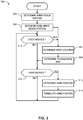
- FIG. 3 an example method 300 that may be performed to enable navigation within a VR environment as disclosed herein is shown.
- the example method 300 of FIG. 3 begins with determining the reachable portion 245 (block 302), and determining the unreachable portion 250 (block 304).
- the location 225 of the head 230 of the user 210 is identified (block 306), and the mapping (e.g., translation, transformation, etc.) that maps locations and movement in the reachable portion 245 into the unreachable portion 250 is determined (block 308).
- the mapping e.g., translation, transformation, etc.
- the location 235 of the hand 240 in the reachable portion is determined (block 312), and the physical hand location 235 is mapped from the location 235 in the reachable portion 245 into the virtual hand location 255 of the virtual hand 260 in the unreachable portion 250 (block 314). Control returns to block 316.
- control returns to block 316 to check for body movement.
- the example method 300 of FIG. 3 may, for example, be implemented as machine-readable instructions carried out by one or more processors to control or operate the example display assemblies disclosed herein.
- a processor, a controller and/or any other suitable processing device may be used, configured and/or programmed to execute and/or carry out the example methods disclosed herein.
- the example method 300 of FIG. 3 , or other methods disclosed herein may be embodied in program code and/or machine-readable instructions stored on a tangible and/or non-transitory computer-readable medium accessible by a processor, a computer and/or other machine having a processor, such as that discussed below in connection with FIG. 4 .
- Machine-readable instructions comprise, for example, instructions that cause a processor, a computer and/or a machine having a processor to perform one or more particular processes.
- Many other methods of implementing the example method 300 of FIG. 3 , or other methods disclosed herein may be employed.
- the order of execution may be changed, and/or one or more of the blocks and/or interactions described may be changed, eliminated, sub-divided, or combined.
- any of the entire example method 300 of FIG. 3 , or other methods disclosed herein may be carried out sequentially and/or carried out in parallel by, for example, separate processing threads, processors, devices, discrete logic, circuits, etc.
- the term "computer-readable medium” is expressly defined to include any type of tangible or non-transitory computer-readable medium and to expressly exclude propagating signals.
- Example computer-readable medium include, but are not limited to, a volatile and/or non-volatile memory, a volatile and/or non-volatile memory device, a compact disc (CD), a digital versatile disc (DVD), a read-only memory (ROM), a random-access memory (RAM), a programmable ROM (PROM), an electronically-programmable ROM (EPROM), an electronically-erasable PROM (EEPROM), an optical storage disk, an optical storage device, a magnetic storage disk, a magnetic storage device, a cache, and/or any other storage media in which information is stored for any duration (e.g., for extended time periods, permanently, brief instances, for temporarily buffering, and/or for caching of the information) and that can be accessed by a processor, a computer and/or other machine having a processor.
- the example network 140 may be constructed using any number and type(s) of private and/or public networks including, but not limited to, the Internet, a cellular data network, a coaxial cable network, a satellite network, a fiber optic network, a dialup or broadband modem over a telephone network, a Wi-Fi® hotspot, a private communications network (e.g., a private local area network (LAN), a wireless local area network (WLAN), a leased line), etc., and any combination thereof.
- private communications network e.g., a private local area network (LAN), a wireless local area network (WLAN), a leased line
- the example system 100 of FIG. 1 further includes the VR content system 130.
- the VR content system 130 may represent a server device.
- the example VR content system 130 of FIG. 1 includes any number of repositories 132 storing content and/or virtual reality applications 134 that can generate, modify, and execute VR scenes.
- the example HMD 110 of FIG. 1 may include, for instance, a VR headset, glasses, an eyepiece, or any other wearable device capable of light-emitting portioning VR content.
- the HMD 110 can, for example, execute a VR application 134 to playback, present, receive or process images for a user. However, images maybe played back, presented and light-emitting portioned by the HMD 110 without need for a VR application 134.
- a VR application 134 of the HMD 110 is hosted by one or more of the devices 126-128 shown in FIG. 1 .
- the one or more VR applications 134 of FIG. 1 can be configured to execute on any or all of the devices 110 and 126-128.
- the HMD 110 can be communicatively coupled to one or more of the devices 126-128 to access VR content stored on or accessible via the VR content system 130.
- the devices 126-128 can be communicatively coupled (wired and/or wirelessly) to the HMD 110.
- the example HMD 110 may be wirelessly coupled to the devices 126-128 via any combination of wireless networks and/or protocols such as, but not limited to, any of the Institute of Electrical and Electronics Engineers (IEEE®) 802.11x family of standards, Wi-Fi®, Bluetooth®, etc.
- IEEE® Institute of Electrical and Electronics Engineers
- a cable with an appropriate connector on either end for plugging into the devices 126-128 may be used.
- the cable can include a Universal Serial Bus (USB) connector on both ends.
- USB Universal Serial Bus
- the USB connectors can be the same USB type connector, or the USB connectors can each be a different type of USB connector.
- USB connectors include, but are not limited to, USB A-type connectors, USB B-type connectors, micro-USB A connectors, micro-USB B connectors, micro-USB AB connectors, USB five pin Mini-b connectors, USB four pin Mini-b connectors, USB 3.0 A-type connectors, USB 3.0 B-type connectors, USB 3.0 Micro B connectors, and USB C-type connectors.
- the mobile device 126 executes the VR application(s) 134 and provides the content for the VR environment.
- the laptop computing device 127 executes the VR application(s) 134 and provides content from one or more content servers (e.g., the VR content server 130).
- the desktop computing device 128 executes the VR application(s) 134 and provides content from one or more content servers (e.g., the VR content server 130).
- the one or more content servers 130 and one or more computer-readable storage devices 132 can communicate with the mobile device 126, the laptop computing device 127, and/or the desktop computing device 128 using the network 140 to provide content for the HMD 110.
- FIG. 4 an example of a generic computer device P00 and a generic mobile computer device P50, which may be used with the techniques described here.
- the computing devices P50 may be used to implement any of the devices disclosed herein including, but not limited to, HMD 110, controller, devices 126-128 and 130, HMD 215 and controller 220.
- Computing device P00 is intended to represent various forms of digital computers, such as laptops, desktops, tablets, workstations, personal digital assistants, televisions, servers, blade servers, mainframes, and other appropriate computing devices.
- Computing device P50 is intended to represent various forms of mobile devices, such as personal digital assistants, cellular telephones, smart phones, and other similar computing devices.
- the components shown here, their connections and relationships, and their functions, are meant to be exemplary only, and are not meant to limit implementations of the inventions described and/or claimed in this document.
- Computing device P00 includes a processor P02, memory P04, a storage device P06, a high-speed interface P08 connecting to memory P04 and high-speed expansion ports P10, and a low speed interface P12 connecting to low speed bus P14 and storage device P06.
- the processor P02 can be a semiconductor-based processor.
- the memory P04 can be a semiconductor-based memory.
- Each of the components P02, P04, P06, P08, P10, and P12, are interconnected using various busses, connections, memories, caches, etc. and may be mounted on a common motherboard or in other manners as appropriate.
- the processor P02 can process instructions for execution within the computing device P00, including instructions stored in the memory P04 or on the storage device P06 to light-emitting portion graphical information for a GUI on an external input/output device, such as light-emitting portion P16 coupled to high speed interface P08.
- multiple processors and/or multiple buses may be used, as appropriate, along with multiple memories and types of memory.
- multiple computing devices P00 may be connected, with each device providing portions of the necessary operations (e.g., as a server bank, a group of blade servers, or a multi-processor system).
- the memory P04 stores information within the computing device P00.
- the memory P04 is a volatile memory unit or units.
- the memory P04 is a non-volatile memory unit or units.
- the memory P04 may also be another form of computer-readable medium, such as a magnetic or optical disk.
- the storage device P06 is capable of providing mass storage for the computing device P00.
- the storage device P06 may be or contain a computer-readable medium, such as a floppy disk device, a hard disk device, an optical disk device, or a tape device, a flash memory or other similar solid state memory device, or an array of devices, including devices in a storage area network or other configurations.
- a computer program product can be tangibly embodied in an information carrier.
- the computer program product may also contain instructions that, when executed, perform one or more methods, such as those described above.
- the information carrier is a computer- or machine-readable medium, such as the memory P04, the storage device P06, or memory on processor P02.
- the high speed controller P08 manages bandwidth-intensive operations for the computing device P00, while the low speed controller P12 manages lower bandwidth-intensive operations.
- the high-speed controller P08 is coupled to memory P04, light-emitting portion P16 (e.g., through a graphics processor or accelerator), and to high-speed expansion ports P10, which may accept various expansion cards (not shown).
- low-speed controller P12 is coupled to storage device P06 and low-speed expansion port P14.
- the low-speed expansion port which may include various communication ports (e.g., USB, Bluetooth, Ethernet, Wi-Fi) may be coupled to one or more input/output devices, such as a keyboard, a pointing device, a scanner, or a networking device such as a switch or router, e.g., through a network adapter.
- input/output devices such as a keyboard, a pointing device, a scanner, or a networking device such as a switch or router, e.g., through a network adapter.
- the computing device P00 may be implemented in a number of different forms, as shown in the figure. For example, it may be implemented as a standard server P20, or multiple times in a group of such servers. It may also be implemented as part of a rack server system P24. In addition, it may be implemented in a personal computer such as a laptop computer P22. Alternatively, components from computing device P00 may be combined with other components in a mobile device (not shown), such as device P50. Each of such devices may contain one or more of computing device P00, P50, and an entire system may be made up of multiple computing devices P00, P50 communicating with each other.
- Computing device P50 includes a processor P52, memory P64, an input/output device such as a light-emitting portion P54, a communication interface P66, and a transceiver P68, among other components.
- the device P50 may also be provided with a storage device, such as a microdrive or other device, to provide additional storage.
- a storage device such as a microdrive or other device, to provide additional storage.
- Each of the components P50, P52, P64, P54, P66, and P68 are interconnected using various buses, and several of the components may be mounted on a common motherboard or in other manners as appropriate.
- the processor P52 can execute instructions within the computing device P50, including instructions stored in the memory P64.
- the processor may be implemented as a chipset of chips that include separate and multiple analog and digital processors.
- the processor may provide, for example, for coordination of the other components of the device P50, such as control of user interfaces, applications run by device P50, and wireless communication by device P50.
- Processor P52 may communicate with a user through control interface P58 and light-emitting portion interface P56 coupled to a light-emitting portion P54.
- the light-emitting portion P54 may be, for example, a TFT LCD (Thin-Film-Transistor Liquid Crystal Light-emitting portion) or an OLED (Organic Light-emitting Diode) light-emitting portion, or other appropriate light-emitting portion technology.
- the light-emitting portion interface P56 may comprise appropriate circuitry for driving the light-emitting portion P54 to present graphical and other information to a user.
- the control interface P58 may receive commands from a user and convert them for submission to the processor P52.
- an external interface P62 may be provided in communication with processor P52, so as to enable near area communication of device P50 with other devices.
- External interface P62 may provide, for example, for wired communication in some implementations, or for wireless communication in other implementations, and multiple interfaces may also be used.
- the memory P64 stores information within the computing device P50.
- the memory P64 can be implemented as one or more of a computer-readable medium or media, a volatile memory unit or units, or a non-volatile memory unit or units.
- Expansion memory P74 may also be provided and connected to device P50 through expansion interface P72, which may include, for example, a SIMM (Single Inline Memory Module) card interface.
- SIMM Single Inline Memory Module
- expansion memory P74 may provide extra storage space for device P50, or may also store applications or other information for device P50.
- expansion memory P74 may include instructions to carry out or supplement the processes described above, and may include secure information also.
- expansion memory P74 may be provide as a security module for device P50, and may be programmed with instructions that permit secure use of device P50.
- secure applications may be provided via the SIMM cards, along with additional information, such as placing identifying information on the SIMM card in a non-hackable manner.
- the memory may include, for example, flash memory and/or NVRAM memory, as discussed below.
- a computer program product is tangibly embodied in an information carrier.
- the computer program product contains instructions that, when executed, perform one or more methods, such as those described above.
- the information carrier is a computer or machine-readable medium, such as the memory P64, expansion memory P74, or memory on processor P5 that may be received, for example, over transceiver P68 or external interface P62.
- Device P50 may communicate wirelessly through communication interface P66, which may include digital signal processing circuitry where necessary. Communication interface P66 may provide for communications under various modes or protocols, such as GSM voice calls, SMS, EMS, or MMS messaging, CDMA, TDMA, PDC, WCDMA, CDMA2000, or GPRS, among others. Such communication may occur, for example, through radio-frequency transceiver P68. In addition, short-range communication may occur, such as using a Bluetooth, Wi-Fi, or other such transceiver (not shown). In addition, GPS (Global Positioning System) receiver module P70 may provide additional navigation- and location-related wireless data to device P50, which may be used as appropriate by applications running on device P50.
- GPS Global Positioning System
- Device P50 may also communicate audibly using audio codec P60, which may receive spoken information from a user and convert it to usable digital information. Audio codec P60 may likewise generate audible sound for a user, such as through a speaker, e.g., in a handset of device P50. Such sound may include sound from voice telephone calls, may include recorded sound (e.g., voice messages, music files, etc.) and may also include sound generated by applications operating on device P50.
- Audio codec P60 may receive spoken information from a user and convert it to usable digital information. Audio codec P60 may likewise generate audible sound for a user, such as through a speaker, e.g., in a handset of device P50. Such sound may include sound from voice telephone calls, may include recorded sound (e.g., voice messages, music files, etc.) and may also include sound generated by applications operating on device P50.
- the computing device P50 may be implemented in a number of different forms, as shown in the figure. For example, it may be implemented as a cellular telephone P80. It may also be implemented as part of a smart phone P82, personal digital assistant, or other similar mobile device.
- implementations of the systems and techniques described here can be realized in digital electronic circuitry, integrated circuitry, specially designed ASICs (application specific integrated circuits), computer hardware, firmware, software, and/or combinations thereof.
- ASICs application specific integrated circuits
- These various implementations can include implementation in one or more computer programs that are executable and/or interpretable on a programmable system including at least one programmable processor, which may be special or general purpose, coupled to receive data and instructions from, and to transmit data and instructions to, a storage system, at least one input device, and at least one output device.
- the systems and techniques described here can be implemented on a computer having a light-emitting portion device (e.g., a CRT (cathode ray tube) or LCD (liquid crystal light-emitting portion) monitor) for light-emitting portioning information to the user and a keyboard and a pointing device (e.g., a mouse or a trackball) by which the user can provide input to the computer.
- a light-emitting portion device e.g., a CRT (cathode ray tube) or LCD (liquid crystal light-emitting portion) monitor
- a keyboard and a pointing device e.g., a mouse or a trackball
- Other kinds of devices can be used to provide for interaction with a user as well; for example, feedback provided to the user can be any form of sensory feedback (e.g., visual feedback, auditory feedback, or tactile feedback); and input from the user can be received in any form, including acoustic, speech, or tactile input.
- the systems and techniques described here can be implemented in a computing system that includes a back end component (e.g., as a data server), or that includes a middleware component (e.g., an application server), or that includes a front end component (e.g., a client computer having a graphical user interface or a Web browser through which a user can interact with an implementation of the systems and techniques described here), or any combination of such back end, middleware, or front end components.
- the components of the system can be interconnected by any form or medium of digital data communication (e.g., a communication network). Examples of communication networks include a local area network ("LAN”), a wide area network (“WAN”), and the Internet.
- LAN local area network
- WAN wide area network
- the Internet the global information network
- the computing system can include clients and servers.
- a client and server are generally remote from each other and typically interact through a communication network.
- the relationship of client and server arises by virtue of computer programs running on the respective computers and having a client-server relationship to each other.
- connecting lines and connectors shown in the various figures presented are intended to represent exemplary functional relationships and/or physical or logical couplings between the various elements. It should be noted that many alternative and/or additional functional relationships, physical connections or logical connections may be present. Moreover, no item or component is essential to the practice of this disclosure unless the element is specifically described as “essential” or “critical”. Additionally, the figures and/or drawings are not drawn to scale, but rather are drawn for clarity of illustration and description.
Landscapes
- Engineering & Computer Science (AREA)
- General Engineering & Computer Science (AREA)
- Theoretical Computer Science (AREA)
- Physics & Mathematics (AREA)
- General Physics & Mathematics (AREA)
- Human Computer Interaction (AREA)
- Software Systems (AREA)
- Computer Graphics (AREA)
- Computer Hardware Design (AREA)
- Remote Sensing (AREA)
- Radar, Positioning & Navigation (AREA)
- Architecture (AREA)
- Optics & Photonics (AREA)
- User Interface Of Digital Computer (AREA)
Claims (15)
- Procédé (300), comprenant
la définition (302) d'une partie accessible (245) d'un environnement de réalité virtuelle (RV) (205), via un contrôleur de réalité virtuelle (220), la partie accessible étant définie par une limite (252) qui a une première taille ;
la définition (304) d'une partie inaccessible (250) de l'environnement RV séparé de la partie accessible, via le contrôleur de réalité virtuelle, la partie inaccessible étant définie par une limite (254) qui a une deuxième taille, la deuxième taille étant différente de la première taille ; et
la translation (314) d'un emplacement de la main physique (235) dans la partie accessible dans un emplacement de la main virtuelle (255) dans la partie inaccessible, caractérisé en ce que ladite translation est effectuée par l'application d'un facteur d'échelle, représentant un rapport des tailles de la partie inaccessible (250) et de la partie accessible (245), avec une différence entre l'emplacement de la main physique (235) et l'emplacement de la tête physique (225), et l'ajout d'un décalage représentant l'emplacement de la tête virtuelle (270). - Procédé selon la revendication 1, dans lequel un objet physique peut être atteint dans la partie accessible.
- Procédé selon la revendication 1, dans lequel la translation de l'emplacement de la main physique dans l'emplacement de la main virtuelle comprend :une translation dans une première direction dans la partie accessible ; etune translation dans une deuxième direction différente de la translation dans la première direction, dans laquelle la première direction comprend une direction à gauche et la deuxième direction comprend une direction à droite.
- Procédé selon la revendication 1, dans lequel la translation de l'emplacement de la main physique dans l'emplacement de la main virtuelle comprend une translation bidimensionnelle (2D) et/ ou une translation tridimensionnelle (3D).
- Procédé selon la revendication 1, dans lequel la définition de la partie accessible comprend la détermination d'un emplacement corporel et d'une amplitude de mouvement autour de l'emplacement corporel.
- Procédé selon la revendication 5, comprenant en outre, lorsque l'emplacement corporel change :la redéfinition de la partie accessible ; etla modification de la translation de l'emplacement de la main physique dans l'emplacement de la main virtuelle.
- Procédé selon la revendication 5, dans lequel l'amplitude de mouvement comprend :une distance accessible dans une première direction ; etune distance inaccessible dans une deuxième direction.
- Procédé selon la revendication 7, dans lequel les distances accessible et inaccessible changent lorsque l'emplacement corporel change.
- Procédé selon la revendication 5, dans lequel la translation de l'emplacement de la main physique dans l'emplacement de la main virtuelle comprend l'application d'un facteur d'échelle à une différence entre l'emplacement de la main physique et l'emplacement corporel.
- Appareil comprenant :
un capteur accessible pour détecter un emplacement de la main physique et un emplacement de la tête physique ; et un processeur programmé pour :définir une partie accessible d'un environnement de réalité virtuelle (RV) via un contrôleur de réalité virtuelle, la partie accessible étant définie par une limite ayant une première taille ;définir une partie inaccessible de l'environnement RV au-delà de la partie accessible via le contrôleur de réalité virtuelle, la partie inaccessible étant définie par une limite qui a une deuxième taille, la deuxième taille étant différente de la première taille ; ettranslater un mouvement de l'emplacement de la main physique détecté dans la partie accessible dans un mouvement de l'emplacement de la main virtuelle dans la partie inaccessible, caractérisée en ce que ladite translation est effectuée par l'application d'un facteur d'échelle, représentant un rapport des tailles de la partie inaccessible et de la partie accessible, avec une différence entre l'emplacement de la main physique et l'emplacement de la tête physique, et l'ajout d'un décalage représentant l'emplacement de la tête virtuelle. - Appareil selon la revendication 10, comprenant en outre un capteur inaccessible pour détecter un emplacement corporel, dans lequel le processeur définit la partie accessible autour de l'emplacement corporel.
- Appareil selon la revendication 10, dans lequel, lorsque l'emplacement corporel change, le processeur redéfinit la partie accessible, et la modification de la translation de l'emplacement de la main physique détecté dans la partie accessible dans l'emplacement de la main virtuelle dans la partie inaccessible.
- Appareil selon la revendication 10, dans lequel l'appareil comprend un dispositif monté sur la tête RV ou un système de contenu RV.
- Un support lisible par machine non transitoire stockant des instructions lisibles par machine qui, lorsqu'elles sont exécutées, amènent une machine à au moins :définir une partie accessible d'un environnement de réalité virtuelle (RV) via un contrôleur de réalité virtuelle, ayant une taille définie par une distance accessible d'un utilisateur dans une forme incurvée ;définir une partie inaccessible de l'environnement RV via le contrôleur de réalité virtuelle, la partie inaccessible étant en dehors de la partie accessible ; etla translation d'un emplacement de la main physique dans la partie accessible dans un emplacement de la main virtuelle dans la partie inaccessible, caractérisée en ce que ladite translation est effectuée par l'application d'un facteur d'échelle, représentant un rapport des tailles de la partie inaccessible (250) et de la portion accessible (245), avec une différence entre l'emplacement de la main physique (235) et l'emplacement de la tête physique (225), et l'ajout d'un décalage représentant l'emplacement de la tête virtuelle (270).
- Milieu non transitoire selon la revendication 14, dans lequel les instructions lisibles par machine, lorsqu'elles sont exécutées, amènent la machine à définir la partie accessible par la détermination d'un emplacement corporel physique et/ ou d'une amplitude de mouvement de la main physique autour de l'emplacement corporel.
Applications Claiming Priority (2)
| Application Number | Priority Date | Filing Date | Title |
|---|---|---|---|
| US15/097,920 US10354446B2 (en) | 2016-04-13 | 2016-04-13 | Methods and apparatus to navigate within virtual-reality environments |
| PCT/US2016/068542 WO2017180206A1 (fr) | 2016-04-13 | 2016-12-23 | Procédés et appareil de navigation dans des environnements de réalité virtuelle |
Publications (2)
| Publication Number | Publication Date |
|---|---|
| EP3384366A1 EP3384366A1 (fr) | 2018-10-10 |
| EP3384366B1 true EP3384366B1 (fr) | 2020-09-16 |
Family
ID=57838505
Family Applications (1)
| Application Number | Title | Priority Date | Filing Date |
|---|---|---|---|
| EP16828853.8A Active EP3384366B1 (fr) | 2016-04-13 | 2016-12-23 | Procédés et appareil de navigation dans des environnements de réalité virtuelle |
Country Status (4)
| Country | Link |
|---|---|
| US (1) | US10354446B2 (fr) |
| EP (1) | EP3384366B1 (fr) |
| CN (1) | CN108475117B (fr) |
| WO (1) | WO2017180206A1 (fr) |
Families Citing this family (13)
| Publication number | Priority date | Publication date | Assignee | Title |
|---|---|---|---|---|
| US10354446B2 (en) | 2016-04-13 | 2019-07-16 | Google Llc | Methods and apparatus to navigate within virtual-reality environments |
| US10405374B2 (en) * | 2017-03-17 | 2019-09-03 | Google Llc | Antenna system for head mounted display device |
| US20180331841A1 (en) * | 2017-05-12 | 2018-11-15 | Tsunami VR, Inc. | Systems and methods for bandwidth optimization during multi-user meetings that use virtual environments |
| CN108771866B (zh) * | 2018-05-29 | 2021-09-24 | 网易(杭州)网络有限公司 | 虚拟现实中的虚拟对象控制方法及装置 |
| US10650239B2 (en) | 2018-07-25 | 2020-05-12 | At&T Intellectual Property I, L.P. | Context-based object location via augmented reality device |
| JP6996450B2 (ja) * | 2018-08-17 | 2022-01-17 | 日本電信電話株式会社 | 画像処理装置、画像処理方法、およびプログラム |
| WO2020068073A1 (fr) | 2018-09-26 | 2020-04-02 | Google Llc | Occultation logicielle pour rendu infographique |
| CN110393916B (zh) * | 2019-07-26 | 2023-03-14 | 腾讯科技(深圳)有限公司 | 视角转动的方法、装置、设备及存储介质 |
| US10705597B1 (en) * | 2019-12-17 | 2020-07-07 | Liteboxer Technologies, Inc. | Interactive exercise and training system and method |
| CN113934290B (zh) * | 2020-07-13 | 2024-11-12 | 阿里巴巴集团控股有限公司 | 虚拟内容显示方法、装置及设备 |
| CN112169330B (zh) * | 2020-09-25 | 2021-12-31 | 腾讯科技(深圳)有限公司 | 虚拟环境的画面显示方法、装置、设备及介质 |
| US12064688B2 (en) * | 2020-12-30 | 2024-08-20 | Activision Publishing, Inc. | Methods and systems for determining decal projections intersecting spatial units in a frame of a game space |
| JP7488856B2 (ja) * | 2022-07-29 | 2024-05-22 | 任天堂株式会社 | ゲームプログラム、ゲームシステム、ゲーム装置およびゲーム制御方法 |
Family Cites Families (11)
| Publication number | Priority date | Publication date | Assignee | Title |
|---|---|---|---|---|
| US7646394B1 (en) | 2004-03-05 | 2010-01-12 | Hrl Laboratories, Llc | System and method for operating in a virtual environment |
| US9399167B2 (en) | 2008-10-14 | 2016-07-26 | Microsoft Technology Licensing, Llc | Virtual space mapping of a variable activity region |
| US8843857B2 (en) | 2009-11-19 | 2014-09-23 | Microsoft Corporation | Distance scalable no touch computing |
| US20120192088A1 (en) | 2011-01-20 | 2012-07-26 | Avaya Inc. | Method and system for physical mapping in a virtual world |
| US20120326966A1 (en) | 2011-06-21 | 2012-12-27 | Qualcomm Incorporated | Gesture-controlled technique to expand interaction radius in computer vision applications |
| US20130007672A1 (en) * | 2011-06-28 | 2013-01-03 | Google Inc. | Methods and Systems for Correlating Head Movement with Items Displayed on a User Interface |
| US20130271371A1 (en) | 2012-04-13 | 2013-10-17 | Utechzone Co., Ltd. | Accurate extended pointing apparatus and method thereof |
| US20150193979A1 (en) * | 2014-01-08 | 2015-07-09 | Andrej Grek | Multi-user virtual reality interaction environment |
| US9864460B2 (en) * | 2014-09-26 | 2018-01-09 | Sensel, Inc. | Systems and methods for manipulating a virtual environment |
| US20160098094A1 (en) | 2014-10-02 | 2016-04-07 | Geegui Corporation | User interface enabled by 3d reversals |
| US10354446B2 (en) | 2016-04-13 | 2019-07-16 | Google Llc | Methods and apparatus to navigate within virtual-reality environments |
-
2016
- 2016-04-13 US US15/097,920 patent/US10354446B2/en active Active
- 2016-12-23 WO PCT/US2016/068542 patent/WO2017180206A1/fr not_active Ceased
- 2016-12-23 EP EP16828853.8A patent/EP3384366B1/fr active Active
- 2016-12-23 CN CN201680078952.2A patent/CN108475117B/zh active Active
Non-Patent Citations (1)
| Title |
|---|
| None * |
Also Published As
| Publication number | Publication date |
|---|---|
| US20170301135A1 (en) | 2017-10-19 |
| US10354446B2 (en) | 2019-07-16 |
| CN108475117A (zh) | 2018-08-31 |
| CN108475117B (zh) | 2021-11-23 |
| EP3384366A1 (fr) | 2018-10-10 |
| WO2017180206A1 (fr) | 2017-10-19 |
Similar Documents
| Publication | Publication Date | Title |
|---|---|---|
| US10354446B2 (en) | Methods and apparatus to navigate within virtual-reality environments | |
| US11893702B2 (en) | Virtual object processing method and apparatus, and storage medium and electronic device | |
| US10795449B2 (en) | Methods and apparatus using gestures to share private windows in shared virtual environments | |
| EP3549003B1 (fr) | Manipulation collaborative d'objets en réalité virtuelle | |
| US9959677B2 (en) | Multidimensional graphical method for entering and exiting applications and activities in immersive media | |
| US9591295B2 (en) | Approaches for simulating three-dimensional views | |
| US10983661B2 (en) | Interface for positioning an object in three-dimensional graphical space | |
| KR20250025752A (ko) | 증강 현실 그래픽들을 디스플레이하는 사용자 인터페이스들의 생성 | |
| US20180113595A1 (en) | Control interface for a three-dimensional graphical object | |
| US11080943B2 (en) | Method and apparatus for displaying with 3D parallax effect | |
| US20250284900A1 (en) | Sign language interpretation with collaborative agents | |
| WO2024158831A1 (fr) | Mise en place d'assistant numérique en réalité étendue | |
| KR20250151480A (ko) | 공동 굽힘 추정 | |
| EP3864494B1 (fr) | Localisation de noeuds sonores spatialisés pour écholocalisation à l'aide d'un apprentissage automatique non supervisé | |
| EP4479819A1 (fr) | Sélection d'objets du monde réel à l'aide d'un dispositif portable | |
| EP3593231B1 (fr) | Procédés et appareil pour interagir avec un objet distant dans un environnement de réalité virtuelle | |
| US20240404168A1 (en) | Techniques for rendering content | |
| CN115937284A (zh) | 一种图像生成方法、设备以及存储介质和程序产品 |
Legal Events
| Date | Code | Title | Description |
|---|---|---|---|
| STAA | Information on the status of an ep patent application or granted ep patent |
Free format text: STATUS: UNKNOWN |
|
| STAA | Information on the status of an ep patent application or granted ep patent |
Free format text: STATUS: THE INTERNATIONAL PUBLICATION HAS BEEN MADE |
|
| PUAI | Public reference made under article 153(3) epc to a published international application that has entered the european phase |
Free format text: ORIGINAL CODE: 0009012 |
|
| STAA | Information on the status of an ep patent application or granted ep patent |
Free format text: STATUS: REQUEST FOR EXAMINATION WAS MADE |
|
| 17P | Request for examination filed |
Effective date: 20180702 |
|
| AK | Designated contracting states |
Kind code of ref document: A1 Designated state(s): AL AT BE BG CH CY CZ DE DK EE ES FI FR GB GR HR HU IE IS IT LI LT LU LV MC MK MT NL NO PL PT RO RS SE SI SK SM TR |
|
| AX | Request for extension of the european patent |
Extension state: BA ME |
|
| DAV | Request for validation of the european patent (deleted) | ||
| DAX | Request for extension of the european patent (deleted) | ||
| GRAP | Despatch of communication of intention to grant a patent |
Free format text: ORIGINAL CODE: EPIDOSNIGR1 |
|
| STAA | Information on the status of an ep patent application or granted ep patent |
Free format text: STATUS: GRANT OF PATENT IS INTENDED |
|
| INTG | Intention to grant announced |
Effective date: 20200407 |
|
| GRAS | Grant fee paid |
Free format text: ORIGINAL CODE: EPIDOSNIGR3 |
|
| GRAA | (expected) grant |
Free format text: ORIGINAL CODE: 0009210 |
|
| STAA | Information on the status of an ep patent application or granted ep patent |
Free format text: STATUS: THE PATENT HAS BEEN GRANTED |
|
| AK | Designated contracting states |
Kind code of ref document: B1 Designated state(s): AL AT BE BG CH CY CZ DE DK EE ES FI FR GB GR HR HU IE IS IT LI LT LU LV MC MK MT NL NO PL PT RO RS SE SI SK SM TR |
|
| REG | Reference to a national code |
Ref country code: GB Ref legal event code: FG4D |
|
| REG | Reference to a national code |
Ref country code: CH Ref legal event code: EP |
|
| REG | Reference to a national code |
Ref country code: DE Ref legal event code: R096 Ref document number: 602016044248 Country of ref document: DE |
|
| REG | Reference to a national code |
Ref country code: IE Ref legal event code: FG4D |
|
| REG | Reference to a national code |
Ref country code: AT Ref legal event code: REF Ref document number: 1314725 Country of ref document: AT Kind code of ref document: T Effective date: 20201015 |
|
| PG25 | Lapsed in a contracting state [announced via postgrant information from national office to epo] |
Ref country code: FI Free format text: LAPSE BECAUSE OF FAILURE TO SUBMIT A TRANSLATION OF THE DESCRIPTION OR TO PAY THE FEE WITHIN THE PRESCRIBED TIME-LIMIT Effective date: 20200916 Ref country code: HR Free format text: LAPSE BECAUSE OF FAILURE TO SUBMIT A TRANSLATION OF THE DESCRIPTION OR TO PAY THE FEE WITHIN THE PRESCRIBED TIME-LIMIT Effective date: 20200916 Ref country code: SE Free format text: LAPSE BECAUSE OF FAILURE TO SUBMIT A TRANSLATION OF THE DESCRIPTION OR TO PAY THE FEE WITHIN THE PRESCRIBED TIME-LIMIT Effective date: 20200916 Ref country code: BG Free format text: LAPSE BECAUSE OF FAILURE TO SUBMIT A TRANSLATION OF THE DESCRIPTION OR TO PAY THE FEE WITHIN THE PRESCRIBED TIME-LIMIT Effective date: 20201216 Ref country code: NO Free format text: LAPSE BECAUSE OF FAILURE TO SUBMIT A TRANSLATION OF THE DESCRIPTION OR TO PAY THE FEE WITHIN THE PRESCRIBED TIME-LIMIT Effective date: 20201216 Ref country code: GR Free format text: LAPSE BECAUSE OF FAILURE TO SUBMIT A TRANSLATION OF THE DESCRIPTION OR TO PAY THE FEE WITHIN THE PRESCRIBED TIME-LIMIT Effective date: 20201217 |
|
| REG | Reference to a national code |
Ref country code: AT Ref legal event code: MK05 Ref document number: 1314725 Country of ref document: AT Kind code of ref document: T Effective date: 20200916 |
|
| REG | Reference to a national code |
Ref country code: NL Ref legal event code: MP Effective date: 20200916 |
|
| PG25 | Lapsed in a contracting state [announced via postgrant information from national office to epo] |
Ref country code: RS Free format text: LAPSE BECAUSE OF FAILURE TO SUBMIT A TRANSLATION OF THE DESCRIPTION OR TO PAY THE FEE WITHIN THE PRESCRIBED TIME-LIMIT Effective date: 20200916 Ref country code: LV Free format text: LAPSE BECAUSE OF FAILURE TO SUBMIT A TRANSLATION OF THE DESCRIPTION OR TO PAY THE FEE WITHIN THE PRESCRIBED TIME-LIMIT Effective date: 20200916 |
|
| REG | Reference to a national code |
Ref country code: LT Ref legal event code: MG4D |
|
| PG25 | Lapsed in a contracting state [announced via postgrant information from national office to epo] |
Ref country code: SM Free format text: LAPSE BECAUSE OF FAILURE TO SUBMIT A TRANSLATION OF THE DESCRIPTION OR TO PAY THE FEE WITHIN THE PRESCRIBED TIME-LIMIT Effective date: 20200916 Ref country code: EE Free format text: LAPSE BECAUSE OF FAILURE TO SUBMIT A TRANSLATION OF THE DESCRIPTION OR TO PAY THE FEE WITHIN THE PRESCRIBED TIME-LIMIT Effective date: 20200916 Ref country code: LT Free format text: LAPSE BECAUSE OF FAILURE TO SUBMIT A TRANSLATION OF THE DESCRIPTION OR TO PAY THE FEE WITHIN THE PRESCRIBED TIME-LIMIT Effective date: 20200916 Ref country code: CZ Free format text: LAPSE BECAUSE OF FAILURE TO SUBMIT A TRANSLATION OF THE DESCRIPTION OR TO PAY THE FEE WITHIN THE PRESCRIBED TIME-LIMIT Effective date: 20200916 Ref country code: PT Free format text: LAPSE BECAUSE OF FAILURE TO SUBMIT A TRANSLATION OF THE DESCRIPTION OR TO PAY THE FEE WITHIN THE PRESCRIBED TIME-LIMIT Effective date: 20210118 Ref country code: RO Free format text: LAPSE BECAUSE OF FAILURE TO SUBMIT A TRANSLATION OF THE DESCRIPTION OR TO PAY THE FEE WITHIN THE PRESCRIBED TIME-LIMIT Effective date: 20200916 |
|
| PG25 | Lapsed in a contracting state [announced via postgrant information from national office to epo] |
Ref country code: AL Free format text: LAPSE BECAUSE OF FAILURE TO SUBMIT A TRANSLATION OF THE DESCRIPTION OR TO PAY THE FEE WITHIN THE PRESCRIBED TIME-LIMIT Effective date: 20200916 Ref country code: AT Free format text: LAPSE BECAUSE OF FAILURE TO SUBMIT A TRANSLATION OF THE DESCRIPTION OR TO PAY THE FEE WITHIN THE PRESCRIBED TIME-LIMIT Effective date: 20200916 Ref country code: ES Free format text: LAPSE BECAUSE OF FAILURE TO SUBMIT A TRANSLATION OF THE DESCRIPTION OR TO PAY THE FEE WITHIN THE PRESCRIBED TIME-LIMIT Effective date: 20200916 Ref country code: PL Free format text: LAPSE BECAUSE OF FAILURE TO SUBMIT A TRANSLATION OF THE DESCRIPTION OR TO PAY THE FEE WITHIN THE PRESCRIBED TIME-LIMIT Effective date: 20200916 Ref country code: IS Free format text: LAPSE BECAUSE OF FAILURE TO SUBMIT A TRANSLATION OF THE DESCRIPTION OR TO PAY THE FEE WITHIN THE PRESCRIBED TIME-LIMIT Effective date: 20210116 |
|
| REG | Reference to a national code |
Ref country code: DE Ref legal event code: R097 Ref document number: 602016044248 Country of ref document: DE |
|
| PG25 | Lapsed in a contracting state [announced via postgrant information from national office to epo] |
Ref country code: SK Free format text: LAPSE BECAUSE OF FAILURE TO SUBMIT A TRANSLATION OF THE DESCRIPTION OR TO PAY THE FEE WITHIN THE PRESCRIBED TIME-LIMIT Effective date: 20200916 |
|
| PLBE | No opposition filed within time limit |
Free format text: ORIGINAL CODE: 0009261 |
|
| STAA | Information on the status of an ep patent application or granted ep patent |
Free format text: STATUS: NO OPPOSITION FILED WITHIN TIME LIMIT |
|
| REG | Reference to a national code |
Ref country code: CH Ref legal event code: PL |
|
| 26N | No opposition filed |
Effective date: 20210617 |
|
| PG25 | Lapsed in a contracting state [announced via postgrant information from national office to epo] |
Ref country code: SI Free format text: LAPSE BECAUSE OF FAILURE TO SUBMIT A TRANSLATION OF THE DESCRIPTION OR TO PAY THE FEE WITHIN THE PRESCRIBED TIME-LIMIT Effective date: 20200916 Ref country code: DK Free format text: LAPSE BECAUSE OF FAILURE TO SUBMIT A TRANSLATION OF THE DESCRIPTION OR TO PAY THE FEE WITHIN THE PRESCRIBED TIME-LIMIT Effective date: 20200916 Ref country code: MC Free format text: LAPSE BECAUSE OF FAILURE TO SUBMIT A TRANSLATION OF THE DESCRIPTION OR TO PAY THE FEE WITHIN THE PRESCRIBED TIME-LIMIT Effective date: 20200916 |
|
| REG | Reference to a national code |
Ref country code: BE Ref legal event code: MM Effective date: 20201231 |
|
| PG25 | Lapsed in a contracting state [announced via postgrant information from national office to epo] |
Ref country code: LU Free format text: LAPSE BECAUSE OF NON-PAYMENT OF DUE FEES Effective date: 20201223 Ref country code: IT Free format text: LAPSE BECAUSE OF FAILURE TO SUBMIT A TRANSLATION OF THE DESCRIPTION OR TO PAY THE FEE WITHIN THE PRESCRIBED TIME-LIMIT Effective date: 20200916 Ref country code: FR Free format text: LAPSE BECAUSE OF NON-PAYMENT OF DUE FEES Effective date: 20201231 Ref country code: IE Free format text: LAPSE BECAUSE OF NON-PAYMENT OF DUE FEES Effective date: 20201223 |
|
| PG25 | Lapsed in a contracting state [announced via postgrant information from national office to epo] |
Ref country code: LI Free format text: LAPSE BECAUSE OF NON-PAYMENT OF DUE FEES Effective date: 20201231 Ref country code: CH Free format text: LAPSE BECAUSE OF NON-PAYMENT OF DUE FEES Effective date: 20201231 |
|
| PG25 | Lapsed in a contracting state [announced via postgrant information from national office to epo] |
Ref country code: TR Free format text: LAPSE BECAUSE OF FAILURE TO SUBMIT A TRANSLATION OF THE DESCRIPTION OR TO PAY THE FEE WITHIN THE PRESCRIBED TIME-LIMIT Effective date: 20200916 Ref country code: MT Free format text: LAPSE BECAUSE OF FAILURE TO SUBMIT A TRANSLATION OF THE DESCRIPTION OR TO PAY THE FEE WITHIN THE PRESCRIBED TIME-LIMIT Effective date: 20200916 Ref country code: CY Free format text: LAPSE BECAUSE OF FAILURE TO SUBMIT A TRANSLATION OF THE DESCRIPTION OR TO PAY THE FEE WITHIN THE PRESCRIBED TIME-LIMIT Effective date: 20200916 |
|
| PG25 | Lapsed in a contracting state [announced via postgrant information from national office to epo] |
Ref country code: MK Free format text: LAPSE BECAUSE OF FAILURE TO SUBMIT A TRANSLATION OF THE DESCRIPTION OR TO PAY THE FEE WITHIN THE PRESCRIBED TIME-LIMIT Effective date: 20200916 |
|
| PG25 | Lapsed in a contracting state [announced via postgrant information from national office to epo] |
Ref country code: BE Free format text: LAPSE BECAUSE OF NON-PAYMENT OF DUE FEES Effective date: 20201231 |
|
| P01 | Opt-out of the competence of the unified patent court (upc) registered |
Effective date: 20230505 |
|
| PG25 | Lapsed in a contracting state [announced via postgrant information from national office to epo] |
Ref country code: NL Free format text: LAPSE BECAUSE OF NON-PAYMENT OF DUE FEES Effective date: 20200923 |
|
| PGFP | Annual fee paid to national office [announced via postgrant information from national office to epo] |
Ref country code: GB Payment date: 20251229 Year of fee payment: 10 |
|
| PGFP | Annual fee paid to national office [announced via postgrant information from national office to epo] |
Ref country code: DE Payment date: 20251229 Year of fee payment: 10 |