EP3384168B1 - Verfahren zur herstellung einer baugruppe - Google Patents
Verfahren zur herstellung einer baugruppe Download PDFInfo
- Publication number
- EP3384168B1 EP3384168B1 EP16801729.1A EP16801729A EP3384168B1 EP 3384168 B1 EP3384168 B1 EP 3384168B1 EP 16801729 A EP16801729 A EP 16801729A EP 3384168 B1 EP3384168 B1 EP 3384168B1
- Authority
- EP
- European Patent Office
- Prior art keywords
- component
- adhesive
- cavity
- assembly
- region
- Prior art date
- Legal status (The legal status is an assumption and is not a legal conclusion. Google has not performed a legal analysis and makes no representation as to the accuracy of the status listed.)
- Active
Links
Images

Classifications
-
- F—MECHANICAL ENGINEERING; LIGHTING; HEATING; WEAPONS; BLASTING
- F16—ENGINEERING ELEMENTS AND UNITS; GENERAL MEASURES FOR PRODUCING AND MAINTAINING EFFECTIVE FUNCTIONING OF MACHINES OR INSTALLATIONS; THERMAL INSULATION IN GENERAL
- F16B—DEVICES FOR FASTENING OR SECURING CONSTRUCTIONAL ELEMENTS OR MACHINE PARTS TOGETHER, e.g. NAILS, BOLTS, CIRCLIPS, CLAMPS, CLIPS OR WEDGES; JOINTS OR JOINTING
- F16B11/00—Connecting constructional elements or machine parts by sticking or pressing them together, e.g. cold pressure welding
- F16B11/006—Connecting constructional elements or machine parts by sticking or pressing them together, e.g. cold pressure welding by gluing
-
- F—MECHANICAL ENGINEERING; LIGHTING; HEATING; WEAPONS; BLASTING
- F16—ENGINEERING ELEMENTS AND UNITS; GENERAL MEASURES FOR PRODUCING AND MAINTAINING EFFECTIVE FUNCTIONING OF MACHINES OR INSTALLATIONS; THERMAL INSULATION IN GENERAL
- F16B—DEVICES FOR FASTENING OR SECURING CONSTRUCTIONAL ELEMENTS OR MACHINE PARTS TOGETHER, e.g. NAILS, BOLTS, CIRCLIPS, CLAMPS, CLIPS OR WEDGES; JOINTS OR JOINTING
- F16B7/00—Connections of rods or tubes, e.g. of non-circular section, mutually, including resilient connections
- F16B7/04—Clamping or clipping connections
- F16B7/044—Clamping or clipping connections for rods or tubes being in angled relationship
- F16B7/048—Clamping or clipping connections for rods or tubes being in angled relationship for rods or for tubes without using the innerside thereof
Definitions
- the present invention relates to a method for producing an assembly which is formed from at least three components.
- plastics In contemporary automobile construction, the aim is to reduce the overall weight in order to reduce fuel consumption and emissions to a minimum. New materials are used that are lighter than the metals previously used.
- the use of plastic lends itself in particular to the formation of body parts, such as flaps, fenders, roofs, etc., for example.
- Fiber-reinforced plastics are used to achieve mechanically high properties.
- Such plastics have a matrix made of a thermosetting or thermoplastic plastic, in the interior of which reinforcing fibers, in particular carbon fibers or glass fibers, are embedded.
- the components can also be glued to one another in industrial production.
- the bonding of assemblies with several components turns out to be difficult, since a certain sequence of the components to be bonded must be adhered to.
- the components can also be glued at the same time, but this results in geometrically complex adhesive seams. The more complex the geometry of the adhesive seam, the more difficult the process-reliable bonding is, since the risk of inclusions or incomplete bonding is high.
- the disclosure document DE 101 18 791 A1 shows a connecting element for hollow profiles, the profiles to be connected being mitred have cut abutting edge and the connecting element has a shape corresponding to the hollow profile cross-section in such a way that one leg of the connecting element can be pushed into the associated hollow profile and secured with fastening means, with holes furthermore being provided in at least one hollow profile through which an adhesive can be filled.
- the WO 98/55771 A1 relates to a connecting element made in sandwich construction for a glued connection at a framework node of a surface or space framework, in particular for the aerospace industry.
- the object of the present invention is to provide a method with which the disadvantages of the prior art are overcome. It is one A specific object of the present invention is to specify a method for producing an assembly which is characterized by high process reliability.
- This cavity comprises a first area, which runs essentially between the second component and the third component, and a second area, which runs essentially between the second component and the first component.
- this essentially means that the first area and the second area are not necessarily separated discretely from one another, but can also merge into one another in edge areas.
- the second component has an opening, an adhesive being introduced through this opening into the first region of the cavity in order to produce the first adhesive connection.
- the adhesive can thus advantageously be supplied on a first side of the assembly, the first adhesive connection being formed in the area of a side that faces away from the first side of the component.
- the first component has an opening, an adhesive being introduced through this opening of the first component into the second region of the cavity in order to produce the second adhesive connection.
- an adhesive connection can advantageously be produced in the interior of the component group via an access on one side of the component group.
- the first adhesive bond is created first and then the second adhesive bond.
- the risk of air inclusions in the adhesive connection is advantageously reduced.
- the first region of the cavity can lie on a side of the second component that faces away from the first component.
- the second region of the cavity can lie on a side of the second component that faces the first component.
- a cavity is created between the components, which cavity comprises a first region that runs essentially between the first section of the first component and the second component and comprises a second region that runs essentially between the second section of the first component runs.
- the first adhesive connection is produced in the first area of the cavity and the second adhesive connection is produced in the second area of the cavity.
- the second component has an opening, an adhesive being introduced through the opening into the first region of the cavity to produce the first adhesive connection.
- the first component has an opening, an adhesive being introduced through this opening into the second region of the cavity in order to produce the second adhesive connection. First the first adhesive bond and then the second adhesive bond is produced.
- the first area of the cavity lies on a side of the second component that faces away from the opening of the first component.
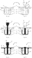
- FIG 1 shows an assembly 10 in an exploded view.
- This assembly 10 comprises a first component 11, a second component 12 and a third component 13, all of which are essentially T-shaped.
- the first component 11 is designed as a flat, thin-walled sheet metal in which three openings 14 are provided.
- the second component 12 is formed from square profiles, which are formed here as solid material, for example. Of course, in alternative forms, the profiles of the second component 12 can also be made hollow.
- the second component 12 also comprises three openings 15 which extend completely through the component 12, namely from a surface of the component 12 that faces the first component 11 to a surface in Figure 1 non-visible surface of the component 12, which faces the third component 13.
- the third component 13 is designed in a shell construction, for example with a U-shaped cross-sectional profile.
- the individual components 11, 12 and 13 are aligned with one another.
- the second component 12 is pushed into the profiled recess of the third component 13 and covered with the first component 11.
- the resulting intermediate assembly 10 is shown in Figure 2 shown.
- This intermediate assembly 10 is a preliminary stage of the assembly 10 'and differs from the assembly in that components 11, 12, 13 are not yet glued to one another.
- the openings 14, 15 are shown by way of example as through bores, and in special embodiments of the invention they can also have other cross-sectional shapes.
- FIG Figures 3a to 3f The further process steps for producing the finished assembly 10 'are shown in FIG Figures 3a to 3f shown. These figures correspond to a sectional illustration through the assembly 10 from FIG Figure 2 along the cutting plane S. As from Figure 3a As can be seen, the opening 14 of the first component 11 and the opening 15 of the second component 12 are aligned with one another. In the assembly 10, a cavity 30 is formed between the components 11, 12, 13.
- a first injector 16 or a first nozzle 16 is placed on the assembly group 10.
- This nozzle 16 comprises an outlet channel 16a through which an injector channel 17 runs.
- the outlet channel 16a can be passed through the opening or through the opening 14 of the first component 11 and placed on the second component 12.
- the outlet 16a ends essentially flush with an inlet opening of the opening 15 in the second component 12.
- the inlet channel 16a as in FIG Figure 3b shown, have a shoulder 16b at its foremost end, the outer diameter of which essentially corresponds to the inner diameter of the opening 15.
- the outlet channel 16a can protrude slightly into the opening 15 and provide a good seal for the Injection channel 17 compared to the second region of the cavity 30 can be achieved.
- an adhesive mass or an adhesive is injected via the injector channel 17 of the first injector 16.
- the adhesive flows through the outlet 16a, into the opening 15, flows through the opening 15 and fills a first region 19 of the cavity 30.
- This method step is in FIG Figure 3c shown.
- the adhesive flows from a figuratively upper side into the opening 15 and out on a lower side of the opening 15, filling the lower area of the cavity 30 and laterally in the gap of the cavity between the component 12 and the Component 13 rises.
- the first adhesive layer or the first adhesive connection 19 is thus produced.
- the adhesive connection 19 shown is located in the first region of the cavity 30, so that the reference number 19 essentially designates the first region of the cavity 30. After the first adhesive layer 19 has been produced, the first injector 16 is removed from the assembly 10.
- a second injector 22 placed on the assembly.
- This has an injector outlet channel 22a which is essentially aligned with the opening 14 of the first component 11.
- the foremost end of the outlet channel 22a of the second injector 22 also advantageously has a shoulder 22b, the outer diameter of which essentially corresponds to the inner diameter of the opening 14 in the first component.
- the second injector 22 or a second nozzle is then used, as in FIG Figure 3e shown, a second adhesive layer 21 or a second Adhesive connection 21 is generated.
- adhesive 20 is injected via the injector channel 23 of the second injector through the outlet 22a of the second injector 22.
- the adhesive mass penetrates into the area between the first component 11 and the second component 12 and thus fills a second area 21 of the cavity 30.
- the second adhesive connection 21 fills a second area 21 of the cavity 30.
- the reference number 21 denotes both the second adhesive connection and also essentially the second area of the cavity 30.
- a two-stage adhesive process can thus be implemented, wherein in a first stage an adhesive is injected with a small nozzle 16 through the inner, second component 12 into a first region 19 of the cavity 30, which is on a side facing away from the attachment point of the nozzle 16 lies.
- the adhesive is injected with a larger nozzle 22 into a second region 21 of the cavity 30, the second region 21 of the cavity 30 facing the larger nozzle 22.
- Different or identical adhesives can be used to produce the first adhesive layer 19 and the second adhesive layer 21.
- the second adhesive layer 21 is preferably injected within the open time of the first adhesive layer 19, so that good adhesion to the first adhesive layer 19 can also be achieved.
- the method offers the advantage that only one-sided access is required on one side of the assembly group 10. This is a major advantage in the body shop, since the injection robot, i. H. the robot arm, which moves the adhesive feed device 16, 22, requires accessibility only on one side of the body.
- the small injector nozzle 16 and the large injector nozzle 22 can be designed as a single tool.
- the injector nozzles 16, 22 are aligned coaxially, the small injector nozzle 16 being essentially inserted in the outlet channel 22a of the large injector nozzle 22.
- the injector nozzles 16, 22 can be displaceable in translation with respect to one another, along their longitudinal axis or along the direction of flow of the adhesive.
- To fill the cavity 30 with adhesive analogous to that in FIG Figures 3a to 3f
- the method described first generates a first adhesive layer 19 by injecting adhesive via the first injection nozzle 16.
- the injection nozzle 16 is then moved back into the interior of the injection nozzle 22.
- the outlet channel 16a of the first injector 16 only needs to be withdrawn to such an extent that the second injector 22 can be placed on the first component 11 in a process-reliable manner.
- the second adhesive layer 21 is then produced by filling the second area 21 of the cavity 30 with adhesive.
- the assembly comprises only two components.
- the structure of such an assembly corresponds to that in Figures 1, 2 and 3 assembly shown, wherein the first component 11 and the third component 13 are formed in one piece, ie integrally and are referred to below as the first component.
- the second component corresponds to the component 12 from the figures.
- the first component comprises a first section 13 'which essentially corresponds to the shape and position of the third component 13 in the Figures 1 to 3 is equivalent to.
- the first component has a second section 11 ', which in its position and shape essentially corresponds to the first component 11 from the figures.
- an assembly is first produced from the first component and the second component, the components being arranged in a predetermined position relative to one another.
- the second component surrounds the first component in the circumferential direction.
- An assembly analogous to the Figures 1 and 2 is not possible with it. Instead, the second component is pushed into the first component until it reaches a predetermined position. In this position, one or more openings 15 in the second component are aligned with one or more openings 14 in the first component.
- a first adhesive connection is also produced here between a first section 13 'of the first component and the second component. If the adhesive 14 is introduced with an injector 16 on one side of the second component 12, a first adhesive connection is produced on the opposite side of the component 12. Similarly to the embodiment described above, a second adhesive connection is established between a second section of the first component and the second component 12. This adhesive connection is then on a side of the component 12 that faces the injector 22.
- the reinforcing fibers can be organic or inorganic reinforcing fibers.
- the reinforcing fibers can be carbon fibers, for example. Together with the plastic matrix, these form a carbon fiber reinforced plastic, Also called CFRP (carbon fiber reinforced plastic; English “Carbon-Fiber-Reinforced Plastic", CFRP).
- CFRP carbon fiber reinforced plastic; English "Carbon-Fiber-Reinforced Plastic", CFRP).
- CFRP carbon fiber reinforced plastic; English "Carbon-Fiber-Reinforced Plastic", CFRP).
- CFRP carbon fiber reinforced plastic
- CFRP Carbon-Fiber-Reinforced Plastic
- the associated FRP component is then a CFRP component.
- the reinforcing fibers can also be glass fibers, for example.
- the associated FRP component is then a GRP component.
- the reinforcing fibers can also, for example, aramid fibers, polyester fibers, nylon fibers, polyethylene fibers, PMMA fibers, Basalt fibers, boron fibers, ceramic fibers, silica fibers, steel fibers and / or natural fibers. Recycled fibers.
- the material of the plastic matrix may in particular comprise one or more thermoplastics (thermoplastics) and / or thermosetting plastics (thermosets).
- Fiber-reinforced plastics with a thermoplastic matrix have the advantage that they can be subsequently formed or welded - as thermoplastics
- suitable plastics are: polyetheretherketone (PEEK), polyphenylene sulfide (PPS), polysulfone (PSU), polyetherimide (PEI) and / or polytetrafluoroethene (PTFE).
- PEEK polyetheretherketone
- PPS polyphenylene sulfide
- PSU polysulfone
- PEI polyetherimide
- PTFE polytetrafluoroethene
- Fiber-reinforced plastics with a thermosetting matrix can no longer be reshaped after the matrix has hardened or cross-linked. They advantageously have a high operating temperature range. This is especially true for hot-curing systems that are cured at high temperatures. Fiber-reinforced plastics with a thermosetting matrix usually have the highest strengths.
- thermosetting plastics or matrices epoxy resin (EP), unsaturated polyester resin (UP), vinyl ester resin (VE), phenol-formaldehyde resin (PF), diallyl phthalate resin (DAP), methacrylate resin (MMA), polyurethane (PUR ), Amino resins, melamine resin (MF / MP) and / or urea resin (UF).
- EP epoxy resin
- UP unsaturated polyester resin
- VE vinyl ester resin
- PF phenol-formaldehyde resin
- DAP diallyl phthalate resin
- MMA methacrylate resin
- PUR polyurethane
- Amino resins melamine resin
- MF / MP / or urea resin
- UF urea resin
- the method can also be used to glue components made of other materials.
- the gluing process offers advantages in that a good mix of materials can be implemented in the assembly group, components made of wood, metal, ceramic and / or plastic can be glued together.
- Adhesive has been described above as a material for producing an adhesive bond. With these adhesive connections, the components to be connected are connected to one another by adhesion. For the purposes of the invention, however, casting compounds are also to be subsumed under the term adhesive. Such casting compounds are also introduced into the cavity in liquid or dough-like form. After the casting compound has hardened, there is a form-fitting connection between the components. Adhesive forces play a subordinate role here.
Landscapes
- Engineering & Computer Science (AREA)
- General Engineering & Computer Science (AREA)
- Mechanical Engineering (AREA)
- Lining Or Joining Of Plastics Or The Like (AREA)
- Adhesives Or Adhesive Processes (AREA)
Description
- Die vorliegende Erfindung betrifft ein Verfahren zur Herstellung einer Baugruppe, die aus mindestens drei Bauteilen ausgebildet ist.
- Im zeitgenössischen Automobilbau wird eine Reduzierung des Gesamtgewichts angestrebt, um Verbrauchs- und Emissionswerte auf ein Mindestmaß herabzusetzen. Dabei kommen neue Werkstoffe zum Einsatz, die leichter sind als die bisher verwendeten Metalle. Insbesondere zur Ausbildung von Karosseriebauteilen, wie beispielsweise Klappen, Kotflügeln, Dächern, usw., bietet sich die Verwendung von Kunststoff an. Zur Erzielung mechanisch hoher Eigenschaften werden faserverstärkte Kunststoffe verwendet. Solche Kunststoffe weisen eine Matrix aus einem duroplastischen oder auch thermoplastischen Kunststoff auf, in deren Inneren Verstärkungsfasern, insbesondere Kohlenstofffasern oder Glasfaser, eingebettet sind.
- Zur Verbindung solcher Bauteile eignen sich kalte Fügetechniken, wie Nieten, Schrauben, usw. Darüber hinaus können bei der industriellen Fertigung die Bauteile auch miteinander verklebt werden. Insbesondere die Verklebung von Baugruppen mit mehreren Bauteilen gestaltet sich schwierig, da hier eine bestimmte Reihenfolge der zu verklebenden Bauteile eingehalten werden muss. Alternativ können die Bauteile auch gleichzeitig verklebt werden, wobei sich jedoch geometrisch komplexe Klebstoffnähte ergeben. Je komplexer die Geometrie der Klebstoffnaht ist, desto schwieriger gestaltet sich die prozesssichere Verklebung, da die Gefahr von Einschlüssen bzw. unvollständiger Verklebung hoch ist.
- Die Offenlegungsschrift
DE 101 18 791 A1 zeigt ein Verbindungselement für Hohlprofile, wobei die zu verbindenden Profile eine auf Gehrung geschnittene Stoßkante aufweisen und das Verbindungselement eine mit dem Hohlprofilquerschnitt derart korrespondierende Form aufweist, dass ein Schenkel des Verbindungselements in das zugeordnete Hohlprofil einschiebbar und mit Befestigungsmitteln festlegbar ist, wobei weiterhin Bohrungen in mindestens einem Hohlprofil vorgesehen sind, über die ein Klebstoff einfüllbar ist. - Die
WO 98/55771 A1 - Aufgabe der vorliegenden Erfindung ist es, ein Verfahren anzugeben, mit dem die Nachteile des Standes der Technik überwunden werden. Es ist eine spezielle Aufgabe der vorliegenden Erfindung ein Verfahren zur Herstellung einer Baugruppe anzugeben, das sich durch hohe Prozesssicherheit auszeichnet.
- Diese Aufgabe wird durch ein Verfahren mit den Merkmalen des unabhängigen Patentanspruchs 1 gelöst. Vorteilhafte Ausführungsformen sind in den abhängigen Patentansprüchen angegeben.
- Zur Lösung dieser Aufgabe lehrt die Erfindung ein Verfahren zur Herstellung einer Baugruppe, wobei die Baugruppe zumindest drei Bauteile umfasst, mit den Schritten
- Erzeugen einer Zusammenbaugruppe aus einem ersten Bauteil, einem zweiten Bauteil und einem dritten Bauteil, wobei die drei Bauteile in einer vorbestimmten Position zueinander angeordnet sind,
- Erzeugen einer ersten Klebstoffverbindung zwischen dem zweiten Bauteil und dem dritten Bauteil, und
- Erzeugen einer zweiten Klebstoffverbindung zwischen dem ersten Bauteil und dem zweiten Bauteil.
- Durch die Erzeugung einer Klebstoffverbindung in einem zweistufigen Verfahren kann eine besonders prozesssichere Verklebung erzeugt werden.
- Weiterhin wird beim Erzeugen der Zusammenbaugruppe eine Kavität zwischen den Bauteilen ausgebildet . Diese Kavität umfasst einen ersten Bereich, der im Wesentlichen zwischen dem zweiten Bauteil und dem dritten Bauteil verläuft, und einen zweiten Bereich, der im Wesentlichen zwischen dem zweiten Bauteil und dem ersten Bauteil verläuft. In diesem Zusammenhang bedeutet im Wesentlichen, dass der erste Bereich und der zweite Bereich nicht notwendigerweise diskret voneinander abgetrennt sind, sondern in Randbereichen auch ineinander übergehen können.
- Weiterhin weist das zweite Bauteil einen Durchbruch auf, wobei zur Erzeugung der ersten Klebstoffverbindung ein Klebstoff durch diesen Durchbruch hindurch in den ersten Bereich der Kavität eingebracht wird.
- Vorteilhafterweise kann somit der Klebstoff auf einer ersten Seite der Baugruppe zugeführt werden, wobei sich die erste Klebstoffverbindung im Bereich einer Seite ausbildet, die der ersten Seite des Bauteils abgewandt ist.
- Zusätzlich weist das erste Bauteil einen Durchbruch auf, wobei zur Erzeugung der zweiten Klebstoffverbindung ein Klebstoff durch diesen Durchbruch des ersten Bauteils in den zweiten Bereich der Kavität eingebracht wird. Auch hier kann vorteilhafterweise über einen Zugang auf einer Seite der Bauteilgruppe eine Klebstoffverbindung im Inneren der Bauteilgruppe erzeugt werden.
- Zum Herstellen der Baugruppe wird zuerst die erste Klebstoffverbindung und danach die zweite Klebstoffverbindung erzeugt . Vorteilhafterweise wird die Gefahr von Lufteinschlüssen in der Klebstoffverbindung reduziert.
- Der erste Bereich der Kavität kann auf einer Seite des zweiten Bauteils liegen, die dem ersten Bauteil abgewandt ist. Der zweite Bereich der Kavität kann auf einer Seite des zweiten Bauteils liegen, die dem ersten Bauteil zugewandt ist.
- In einer weiteren alternativen Ausführungsform können das im Vorhergehenden beschriebene erste Bauteil und das dritte Bauteil integral bzw. einstückig ausgebildet sein. Ein Verfahren zur Herstellung einer solchen Baugruppe mit zumindest zwei Bauteilen umfasst die Schritte:
- Erzeugen einer Zusammenbaugruppe aus einem ersten Bauteil und einem zweiten Bauteil, wobei die Bauteile in einer vorbestimmten Position zueinander angeordnet sind,
- Erzeugen einer ersten Klebstoffverbindung zwischen einem ersten Abschnitt des ersten Bauteils und dem zweiten Bauteil, und
- Erzeugen einer zweiten Klebstoffverbindung zwischen einem zweiten Abschnitt des ersten Bauteils und dem zweiten Bauteil.
- Auch in dem Verfahren gemäß dieser Ausführungsform entsteht beim Erzeugen der Zusammenbaugruppe eine Kavität zwischen den Bauteilen, die einen ersten Bereich umfasst, der im Wesentlichen zwischen dem ersten Abschnitt des ersten Bauteil und dem zweiten Bauteil verläuft und einen zweiten Bereich umfasst, der im Wesentlichen zwischen dem zweiten Abschnitt des ersten Bauteils verläuft.
- Die erste Klebstoffverbindung wird in dem ersten Bereich der Kavität und die zweite Klebstoffverbindung in dem zweiten Bereich der Kavität erzeugt .
- Auch in diesem Verfahren hat das zweite Bauteil einen Durchbruch, wobei zur Erzeugung der ersten Klebstoffverbindung ein Klebstoff durch den Durchbruch hindurch in den ersten Bereich der Kavität eingebracht wird. Darüber hinaus weist das erste Bauteil einen Durchbruch auf, wobei zur Erzeugung der zweiten Klebstoffverbindung ein Klebstoff durch diesen Durchbruch in den zweiten Bereich der Kavität eingebracht wird. Zuerst wird die erste Klebstoffverbindung und danach die zweite Klebstoffverbindung erzeugt.
- Der erste Bereich der Kavität liegt auf einer Seite des zweiten Bauteils, die dem Durchbruch des ersten Bauteils abgewandt ist.
- Nachfolgend soll die Erfindung anhand der Figurenbeschreibung näher erläutert werden. Die Beschreibung, die Ansprüche und die Zeichnungen zeigen eine Vielzahl von Merkmalen, die ein Fachmann auch in anderer Kombination in Betracht ziehen würde, um die Erfindung an entsprechende Anwendungen anzupassen.
- Es zeigen in schematischer Darstellung:
- Figur 1
- eine perspektivische Darstellung einer Baugruppe als Explosionszeichnung,
- Figur 2
- eine perspektivische Darstellung der Baugruppe in zusammengesetztem Zustand,
- Figuren 3a bis 3f
- einzelne Verfahrensschritte zur Herstellung der Baugruppe.
-
Figur 1 zeigt eine Baugruppe 10 in Explosionsdarstellung. Diese Baugruppe 10 umfasst ein erstes Bauteil 11, ein zweites Bauteil 12 und ein drittes Bauteil 13, die alle im Wesentlichen T-förmig ausgebildet sind. Das erste Bauteil 11 ist als flaches, dünnwandiges Blech ausgebildet, in dem drei Durchbrüche 14 vorgesehen sind. Das zweite Bauteil 12 ist aus Vierkantprofilen ausgebildet, die hier beispielhaft als Vollmaterial ausgebildet sind. Selbstverständlich können in alternativen Formen die Profile des zweiten Bauteils 12 auch hohl ausgebildet sein. Das zweite Bauteil 12 umfasst ebenfalls drei Durchbrüche 15, welche sich vollständig durch das Bauteil 12 hindurchziehen, und zwar von einer Oberfläche des Bauteils 12, die dem ersten Bauteil 11 zugewandt ist, zu einer inFigur 1 nicht sichtbaren Oberfläche des Bauteils 12, die dem dritten Bauteil 13 zugewandt ist. Das dritte Bauteil 13 ist in Schalenbauweise ausgebildet, beispielhaft mit einem U-förmigen Querschnittsprofil. In einem ersten Verfahrensschritt zur Herstellung der Bauteilgruppe werden die einzelnen Bauteile 11, 12 und 13 zueinander ausgerichtet. Dabei wird das zweite Bauteil 12 in die profilierte Vertiefung des dritten Bauteils 13 eingeschoben und mit dem ersten Bauteil 11 abgedeckt. Die dabei entstehende Zwischenbaugruppe 10 ist inFigur 2 dargestellt. Diese Zwischenbaugruppe 10 ist eine Vorstufe der Baugruppe 10' und unterscheidet sich von der Baugruppe dadurch, dass Bauteile 11, 12, 13 noch nicht miteinander verklebt sind. Die Durchbrüche 14, 15 sind beispielhaft als Durchgangsbohrungen dargestellt, wobei sie in speziellen Ausführungsformen der Erfindung auch andere Querschnittsformen aufweisen können. - Die weiteren Verfahrensschritte zur Herstellung der fertigen Baugruppe 10' sind in den
Figuren 3a bis 3f dargestellt. Diese Figuren entsprechen einer Schnittdarstellung durch die Zusammenbaugruppe 10 ausFigur 2 entlang der Schnittebene S. Wie ausFigur 3a ersichtlich ist, sind der Durchbruch 14 des ersten Bauteils 11 und der Durchbruch 15 des zweiten Bauteils 12 zueinander fluchtend ausgerichtet. In der Zusammenbaugruppe 10 ist zwischen den Bauteilen 11, 12, 13 eine Kavität 30 ausgebildet. - In einem folgenden Verfahrensschritt wird ein erster Injektor 16 bzw. eine erste Düse 16 auf die Zusammenbaugruppe 10 aufgesetzt. Diese Düse 16 umfasst einen Auslasskanal 16a durch den ein Injektorkanal 17 verläuft. Der Auslasskanal 16a kann durch die Öffnung bzw. durch den Durchbruch 14 des ersten Bauteils 11 hindurchgeführt werden und auf das zweite Bauteil 12 aufgesetzt werden. Dabei schließt der Auslass 16a im Wesentlichen bündig mit einer Einlassöffnung des Durchbruchs 15 im zweiten Bauteil 12 ab. Vorteilhafterweise kann der Einlasskanal 16a, wie in
Figur 3b dargestellt, an seinem vordersten Ende einen Absatz 16b aufweisen, dessen Außendurchmesser im Wesentlichen dem Innendurchmesser des Durchbruchs 15 entspricht. Dadurch kann der Auslasskanal 16a geringfügig in den Durchbruch 15 hineinragen und eine gute Abdichtung des Injektionskanals 17 gegenüber dem zweiten Bereich der Kavität 30 erzielt werden. - Nach dem Aufsetzen des ersten Injektors 16 wird über den Injektorkanal 17 des ersten Injektors 16 eine Klebstoffmasse bzw. ein Klebstoff, insbesondere ein Zweikomponentenklebstoff, injiziert. Der Klebstoff fließt dabei durch den Auslass 16a hindurch, in den Durchbruch 15 hinein, durchströmt den Durchbruch 15 und befüllt einen ersten Bereich 19 der Kavität 30. Dieser Verfahrensschritt ist in
Figur 3c dargestellt. Wie daraus ersichtlich ist, strömt der Klebstoff von einer figürlich oberen Seite in den Durchbruch 15 hinein und auf einer unteren Seite des Durchbruchs 15 hinaus, wobei er den unteren Bereich der Kavität 30 füllt und seitlich in dem Spalt der Kavität zwischen dem Bauteil 12 und dem Bauteil 13 aufsteigt. Somit wird die erste Klebstoffschicht bzw. die erste Klebstoffverbindung 19 erzeugt. Die in denFigur 3c und 3d gezeigte Klebstoffverbindung 19 befindet sich in dem ersten Bereich der Kavität 30, so dass die Bezugsziffer 19 im Wesentlichen den ersten Bereich der Kavität 30 bezeichnet. Nach dem Erzeugen der ersten Klebstoffschicht 19 wird der erste Injektor 16 von der Zusammenbaugruppe 10 entfernt. - Danach wird, wie in
Figur 3d dargestellt, ein zweiter Injektor 22 auf die Zusammenbaugruppe aufgesetzt. Dieser hat einen Injektorauslasskanal 22a, der im Wesentlichen fluchtend mit dem Durchbruch 14 des ersten Bauteils 11 ausgerichtet wird. Analog zum ersten Injektor 16 weist vorteilhafterweise auch das vorderste Ende des Auslasskanals 22a des zweiten Injektors 22 einen Absatz 22b auf, dessen Außendurchmesser im Wesentlichen dem Innendurchmesser des Durchbruchs14 im ersten Bauteil entspricht. Dadurch kann eine Positionierung realisiert werden, bei der der Absatz den zweiten Injektor 22 in dem ersten Bauteil 11 zentriert positioniert und gleichzeitig eine gute Abdichtung gegenüber der Umgebung erzielt werden. Mit dem zweiten Injektor 22 bzw. mit einer zweiten Düse wird danach, wie inFigur 3e dargestellt, eine zweite Klebstoffschicht 21 bzw. eine zweite Klebstoffverbindung 21 erzeugt. Dabei wird Klebstoff 20 über den Injektorkanal 23 des zweiten Injektors durch den Auslass 22a des zweiten Injektors 22 injiziert. Die Klebstoffmasse dringt in den Bereich zwischen dem ersten Bauteil 11 und dem zweiten Bauteil 12 und füllt so einen zweiten Bereich 21 der Kavität 30 auf. Wie bereits oben mit Bezug zur ersten Klebverbindung 19 beschrieben, füllt die zweite Klebverbindung 21 einen zweiten Bereich 21 der Kavität 30 aus. Somit beziffert das Bezugszeichen 21 sowohl die zweite Klebeverbindung, wie auch im Wesentlichen den zweiten Bereich der Kavität 30. - Nach dem Abnehmen des zweiten Injektors 22 von der Zusammenbaugruppe 10 ist die Baugruppe 10' fertiggestellt, wobei die Klebstoffschichten 19 und 21 verfestigt sind. Das Endprodukt des Verfahrens ist in
Figur 3f dargestellt. - Erfindungsgemäß kann somit ein zweistufiges Klebeverfahren realisiert werden, wobei in einer ersten Stufe ein Klebstoff mit einer kleinen Düse 16 durch das innere, zweite Bauteil 12 hindurch in einen ersten Bereich 19 der Kavität 30 injiziert wird, der auf einer abgewandten Seite des Ansetzpunktes der Düse 16 liegt. In einer zweiten Stufe wird der Klebstoff mit einer größeren Düse 22 in einen zweiten Bereich 21 der Kavität 30 injiziert, wobei der zweite Bereich 21 der Kavität 30 der größeren Düse 22 zugewandt ist. Zur Erzeugung der ersten Klebeschicht 19 und der zweiten Klebeschicht 21 können verschiedene oder gleiche Klebstoff verwendet werden. Bevorzugt wird die zweite Klebstoffschicht 21 innerhalb der Offenzeit der ersten Klebstoffschicht 19 injiziert, so dass eine gute Haftung auch zur ersten Klebstoffschicht 19 erzielt werden kann. Dieses Verfahren bietet Vorteile dahingehend, dass Lufteinschlüsse vermieden werden können, indem zuerst eine Klebstoffschicht auf einer abgewandten Seite des zweiten Bauteils 12 erzeugt wird und danach eine Klebstoffschicht auf der zugewandten Seite des Bauteils 12.
- Darüber hinaus kann auch mit geringen Injektionsdrücken gearbeitet werden. Ferner bietet das Verfahren den Vorteil, dass nur ein einseitiger Zugang auf einer Seite der Zusammenbaugruppe 10 benötigt wird. Dies ist ein wesentlicher Vorteil im Karosseriebau, da der Injektionsroboter, d. h. der Roboterarm, der die Klebstoffzuführeinrichtung 16, 22 bewegt, nur auf einer Seite der Karosserie eine Zugänglichkeit benötigt.
- In einer weiteren, nicht dargestellten Ausführungsform des Verfahrens können die kleine Injektordüse 16 und die große Injektordüse 22 als ein einziges Werkzeug ausgebildet sein. Dazu sind die Injektordüsen 16, 22 koaxial ausgerichtet, wobei die kleine Injektordüse 16 im Wesentlichen in dem Auslasskanal 22a der großen Injektordüse 22 eingesetzt ist. Die Injektordüsen 16, 22 können dabei zueinander translatorisch verschiebbar sein, entlang ihrer Längsachse bzw. entlang der Fließrichtung des Klebstoffs. Zur Befüllung der Kavität 30 mit Klebstoff wird somit analog zu dem in den
Figuren 3a bis 3f beschriebenen Verfahren zunächst eine erste Klebstoffschicht 19 erzeugt, durch Injektion von Klebstoff über die erste Injektionsdüse 16. Danach wird die Injektionsdüse 16 ins Innere der Injektionsdüse 22 zurückgefahren. Der Auslasskanal 16a des ersten Injektors 16 muss dabei nur soweit zurückgezogen werden, dass ein prozesssicheres Aufsetzen des zweiten Injektors 22 auf das erste Bauteil 11 möglich ist. Anschließend wird die zweite Klebstoffschicht 21 erzeugt, indem der zweite Bereich 21 der Kavität 30 mit Klebstoff gefüllt wird. - In einer weiteren, figürlich nicht dargestellten, Ausführungsform umfasst die Baugruppe nur zwei Bauteile. Der Aufbau einer solchen Baugruppe entspricht dabei der in den
Figuren 1, 2 und3 dargestellten Baugruppe, wobei das erste Bauteil 11 und das dritte Bauteil 13 einstückig, d.h. integral ausgebildet sind und im Folgenden als erstes Bauteil bezeichnet werden. Das zweite Bauteil entspricht dabei dem Bauteil 12 aus den Figuren. Das erste Bauteil umfasst einen ersten Abschnitt 13', der im Wesentlichen der Form und der Position des dritten Bauteils 13 in denFiguren 1 bis 3 entspricht. Darüber hinaus weist das erste Bauteil einen zweiten Abschnitt 11' auf, der in seiner Position und seiner Form im Wesentlichen dem ersten Bauteil 11 aus den Figuren entspricht. Zur Herstellung einer solchen Baugruppe wird zuerst eine Zusammenbaugruppe aus dem ersten Bauteil und dem zweiten Bauteil erzeugt, wobei die Bauteile in einer vorbestimmten Position zueinander angeordnet werden. In dieser Ausführungsform umschließt das zweite Bauteil das erste Bauteil in Umfangsrichtung. Ein Zusammenbau analog zu denFiguren 1 und 2 ist damit nicht möglich. Stattdessen wird das zweite Bauteil in das erste Bauteil eingeschoben, bis es eine vorbestimmte Position erreicht. In dieser Position sind ein oder mehrere Durchbrüche 15 in dem zweiten Bauteil zu einem oder mehreren Durchbrüchen 14 in dem ersten Bauteil fluchtend ausgerichtet. - Analog zu der oben beschriebenen Ausführungsform wird auch hier eine erste Klebstoffverbindung erzeugt zwischen einem ersten Abschnitt 13' des ersten Bauteils und dem zweiten Bauteil. Wenn der Klebstoff 14 mit einem Injektor 16 auf einer Seite des zweiten Bauteils 12 eingebracht wird, so wird eine erste Klebstoffverbindung auf der gegenüberliegenden Seite des Bauteils 12 erzeugt. Ebenfalls analog zur oben beschriebenen Ausführungsform wird eine zweite Klebstoffverbindung zwischen einem zweiten Abschnitt des ersten Bauteils und dem zweiten Bauteil 12. Diese Klebstoffverbindung liegt dann auf einer Seite der Bauteils 12, die dem Injektor 22 zugewandt ist.
- Alle im Vorhergehenden beschriebenen Ausführungsformen bieten den Vorteil einer geringen Taktzeit bzw. einer hohen Taktfrequenz. Dieses Klebeverfahren eignet sich insbesondere bei Bauteilen aus faserverstärktem Kunststoff, beispielsweise glasfaserverstärkten Kunststoffbauteilen oder kohlenstofffaserverstärkten Kunststoffbauteilen. Die Verstärkungsfasern können organische oder anorganische Verstärkungsfasern sein. Die Verstärkungsfasern können beispielsweise Kohlenstofffasern sein. Diese bilden mit der Kunststoffmatrix einen kohlenstofffaserverstärkten Kunststoff, auch CFK (Carbon-faserverstärkter Kunststoff; englisch ,,Carbon-Fiber-Reinforced Plastic", CFRP) genannt. Das zugehörige FVK-Bauteil ist dann ein CFK- Bauteil. Die Verstärkungsfasern können beispielsweise auch Glasfasern sein. Diese bilden mit der Kunststoffmatrix einen glasfaserverstärkten Kunststoff, auch GFK genannt. Das zugehörige FVK-Bauteil ist dann ein GFK-Bauteil. Jedoch ist die Erfindung nicht darauf beschränkt, und die Verstärkungsfasern können z.B. auch Aramidfasern, Polyester-Fasern, Nylon-Fasern, Polyethylen-Fasern, PMMA-Fasern, Basaltfasern, Borfasern, Keramikfasern, Kieselsäurefasern, Stahl-Fasern und/oder Naturfasern sein. Recyclingfasern. Das Material der Kunststoffmatrix mag insbesondere ein oder mehrere thermoplastische Kunststoffe (Thermoplaste) und/oder duroplastische Kunststoffe (Duroplaste) aufweisen. Faserverstärkte Kunststoffe mit einer thermoplastischen Matrix weisen den Vorteil auf, dass sie sich nachträglich umformen oder verschweißen lassen. Als thermoplastische Kunststoffe eignen sich beispielsweise: Polyetheretherketon (PEEK), Polyphenylensulfid (PPS), Polysulfon (PSU), Polyetherimid (PEI) und/oder Polytetrafluorethen (PTFE). Faserverstärkte Kunststoffe mit einer duroplastischen Matrix lassen sich nach dem Aushärten bzw. dem Vernetzen der Matrix nicht mehr umformen. Sie weisen vorteilhafterweise einen hohen Temperatureinsatzbereich auf. Dies gilt besonders für heißhärtende Systeme, die unter hohen Temperaturen ausgehärtet werden. Faserverstärkte Kunststoffe mit duroplastischer Matrix weisen meist die höchsten Festigkeiten auf. Als duroplastische Kunststoffe bzw. Matrix können z.B. folgende Harze zur Anwendung kommen: Epoxidharz (EP), ungesättigtes Polyesterharz (UP), Vinylesterharz (VE), Phenol-Formaldehydharz (PF), Diallylphthalatharz (DAP), Methacrylatharz (MMA), Polyurethan (PUR), Aminoharze, Melaminharz (MF/MP) und/oder Harnstoffharz (UF). Selbstverständlich kann das Verfahren auch zum Verkleben von Bauteilen aus anderen Materialien verwendet werden. Das Klebeverfahren bietet Vorteile dahingehend, dass ein guter Materialmix in der Zusammenbaugruppe realisiert werden kann, wobei Bauteile aus Holz, Metall, Keramik und/oder Kunststoff miteinander verklebt werden können.
- Im Vorhergehenden wurde Klebstoff als Materials zur Herstellung einer Klebstoffverbindung beschrieben. Bei diesen Klebstoffverbindungen werden die zu verbindenden Bauteile durch Adhäsion miteinander verbunden. Im Sinne der Erfindung sind jedoch auch Gussmassen unter den Begriff Klebstoff zu subsummieren. Solche Gussmassen werden ebenfalls in flüssiger oder teigartiger Form in die Kavität eingebracht. Nach der Aushärtung der Gussmasse ergibt sich eine formschlüssige Verbindung zwischen den Bauteilen. Adhäsionskräfte spielen dabei eine untergeordnete Rolle.
-
- 10
- Baugruppe
- 11
- erstes Bauteil
- 12
- zweites Bauteil
- 13
- drittes Bauteil
- 14
- Durchbruch des ersten Bauteils
- 15
- Durchbruch des zweiten Bauteils
- 16
- erster Injektor
- 17
- Injektorkanal des ersten Injektors
- 18
- erster Klebstoff
- 19
- erste Klebstoffschicht
- 20
- zweiter Klebstoff
- 21
- zweite Klebstoffschicht
- 22
- zweiter Injektor
- 23
- Injektorkanal des zweiten Injektors
Claims (7)
- Verfahren zur Herstellung einer Baugruppe (10'), umfassend zumindest drei Bauteile (11, 12, 13), mit den Schritten:- Erzeugen einer Zusammenbaugruppe (10) aus einem ersten Bauteil (11), einem zweiten Bauteil (12) und einem dritten Bauteil (13), wobei die drei Bauteile (11, 12, 13) in einer vorbestimmten Position zueinander angeordnet sind, wobei beim Erzeugen der Zusammenbaugruppe (10) eine Kavität (30) zwischen den Bauteilen (11, 12, 13) entsteht, die einen ersten Bereich umfasst, der im Wesentlichen zwischen dem zweiten Bauteil (12) und dem dritten Bauteil (13) verläuft und einen zweiten Bereich umfasst, der im Wesentlichen zwischen dem zweiten Bauteil (12) und dem ersten Bauteil (11) verläuft,- Erzeugen einer ersten Klebstoffverbindung (19) zwischen dem zweiten Bauteil (12) und dem dritten Bauteil (13), und- Erzeugen einer zweiten Klebstoffverbindung (21) zwischen dem ersten Bauteil (11) und dem zweiten Bauteil (12),dadurch gekennzeichnet, dass
das zweite Bauteil (12) einen Durchbruch (15) aufweist und dass zur Erzeugung der ersten Klebstoffverbindung (19) ein Klebstoff durch den Durchbruch (15) hindurch in den ersten Bereich der Kavität eingebracht wird und, dass
das erste Bauteil (11) einen Durchbruch (14) aufweist, wobei zur Erzeugung der zweiten Klebstoffverbindung (21) ein Klebstoff durch den Durchbruch (14) in den zweiten Bereich (21) der Kavität eingebracht wird, wobei zuerst die erste Klebstoffverbindung (19) und danach die zweite Klebstoffverbindung (21) erzeugt wird. - Verfahren nach Anspruch 1, dadurch gekennzeichnet, dass die erste Klebstoffverbindung (19) in dem ersten Bereich der Kavität erzeugt wird und die zweite Klebstoffverbindung (21) in dem zweiten Bereich der Kavität erzeugt wird.
- Verfahren nach einem der Patentansprüche 1 oder 2, dadurch gekennzeichnet, dass
der erste Bereich (19) der Kavität auf einer Seite des zweiten Bauteils (12) liegt, die dem ersten Bauteil (11) abgewandt ist. - Verfahren nach einem der Patentansprüche 1 bis 3, dadurch gekennzeichnet, dass
der zweite Bereich (21) der Kavität auf einer Seite des zweiten Bauteils (12) liegt, die dem ersten Bauteil (11) zugewandt ist. - Verfahren zur Herstellung einer Baugruppe, umfassend zumindest zwei Bauteile, mit den Schritten:- Erzeugen einer Zusammenbaugruppe aus einem ersten Bauteil und einem zweiten Bauteil, wobei die Bauteile in einer vorbestimmten Position zueinander angeordnet sind, wobei beim Erzeugen der Zusammenbaugruppe eine Kavität (30) zwischen den Bauteilen entsteht, die einen ersten Bereich (19) umfasst, der im Wesentlichen zwischen dem ersten Abschnitt (13') des ersten Bauteil und dem zweiten Bauteil (11') verläuft und einen zweiten Bereich (21) umfasst, der im Wesentlichen zwischen dem zweiten Abschnitt (11') des ersten Bauteils und dem zweiten Bauteil verläuft,- Erzeugen einer ersten Klebstoffverbindung (19) zwischen einem ersten Abschnitt (13') des ersten Bauteils und dem zweiten Bauteil (12), und- Erzeugen einer zweiten Klebstoffverbindung (21) zwischen einem zweiten Abschnitt (11') des ersten Bauteil und dem zweiten Bauteil (12),dadurch gekennzeichnet, dass- das zweite Bauteil (12) einen Durchbruch (15) aufweist und zur Erzeugung der ersten Klebstoffverbindung (19) ein Klebstoff durch den Durchbruch (15) hindurch in den ersten Bereich der Kavität eingebracht wird, und- das erste Bauteil einen Durchbruch (14) aufweist, und zur Erzeugung der zweiten Klebstoffverbindung (21) ein Klebstoff durch den Durchbruch (14) in den zweiten Bereich (21) der Kavität eingebracht wird, wobei zuerst die erste Klebstoffverbindung (19) und danach die zweite Klebstoffverbindung (21) erzeugt wird.
- Verfahren nach Anspruch 5, dadurch gekennzeichnet, dass die erste Klebstoffverbindung (19) in dem ersten Bereich der Kavität erzeugt wird und die zweite Klebstoffverbindung (21) in dem zweiten Bereich der Kavität erzeugt wird.
- Verfahren nach einem der Patentansprüche 5 bis 6, dadurch gekennzeichnet, dass
der erste Bereich (19) der Kavität auf einer Seite des zweiten Bauteils (12) liegt, die dem Durchbruch (14) des ersten Bauteils (11') abgewandt ist.
Applications Claiming Priority (2)
| Application Number | Priority Date | Filing Date | Title |
|---|---|---|---|
| DE102015223962.4A DE102015223962A1 (de) | 2015-12-02 | 2015-12-02 | Verfahren zur Herstellung einer Baugruppe |
| PCT/EP2016/077917 WO2017093025A1 (de) | 2015-12-02 | 2016-11-17 | Verfahren zur herstellung einer baugruppe |
Publications (2)
| Publication Number | Publication Date |
|---|---|
| EP3384168A1 EP3384168A1 (de) | 2018-10-10 |
| EP3384168B1 true EP3384168B1 (de) | 2021-09-15 |
Family
ID=57406213
Family Applications (1)
| Application Number | Title | Priority Date | Filing Date |
|---|---|---|---|
| EP16801729.1A Active EP3384168B1 (de) | 2015-12-02 | 2016-11-17 | Verfahren zur herstellung einer baugruppe |
Country Status (5)
| Country | Link |
|---|---|
| US (1) | US10935062B2 (de) |
| EP (1) | EP3384168B1 (de) |
| CN (1) | CN107923426B (de) |
| DE (1) | DE102015223962A1 (de) |
| WO (1) | WO2017093025A1 (de) |
Families Citing this family (5)
| Publication number | Priority date | Publication date | Assignee | Title |
|---|---|---|---|---|
| CN110573754B (zh) * | 2017-03-01 | 2022-07-12 | 福特全球技术公司 | 用于3d打印的车辆架构即接头的组装方法 |
| PL3642100T3 (pl) | 2017-06-22 | 2024-04-29 | Sika Technology Ag | Sposób łączenia elementów w pojazdach mechanicznych |
| US11231060B2 (en) * | 2019-01-16 | 2022-01-25 | Bruce Daniel McFall | Hybrid tension/transverse compression structural joint |
| DE102020211958A1 (de) | 2020-09-24 | 2022-03-24 | Volkswagen Aktiengesellschaft | Verfahren zum Verbinden von Profilelementen und Profilkonstruktion |
| WO2022076718A1 (en) * | 2020-10-08 | 2022-04-14 | Zephyros, Inc. | Connector assembly and method of making |
Family Cites Families (8)
| Publication number | Priority date | Publication date | Assignee | Title |
|---|---|---|---|---|
| IT1268634B1 (it) * | 1994-10-21 | 1997-03-06 | Fiat Auto Spa | Procedimento di assemblaggio di elementi tubolari. |
| AU722554B2 (en) | 1996-05-10 | 2000-08-03 | Henkel Kommanditgesellschaft Auf Aktien | Internal reinforcement for hollow structural elements |
| DE19723112C1 (de) * | 1997-06-03 | 1999-06-02 | Ulrich Dipl Ing Rueger | Verbindungselement für eine geklebte Verbindung zwischen zwei oder mehr Stäben |
| DE10118791B4 (de) * | 2001-04-18 | 2012-06-21 | Adrian Kosak | Verbindungselement |
| US7115324B1 (en) * | 2003-08-29 | 2006-10-03 | Alcoa Inc. | Method of combining welding and adhesive bonding for joining metal components |
| CN101128355A (zh) * | 2005-02-28 | 2008-02-20 | 陶氏环球技术公司 | 粘合元件的方法和用该方法形成的物品 |
| BRPI0608031A2 (pt) * | 2005-02-28 | 2009-11-03 | Dow Global Technologies Inc | método para fabricação de um conjunto de veìculo de transporte |
| DE102014002612B3 (de) * | 2014-02-27 | 2015-08-06 | Imperia Gesellschaft für angewandte Fahrzeugentwicklung mbH | Verfahren zur Herstellung eines Leichtbauteils sowie Komponentensatz zur Verwendung in einem entsprechenden Verfahren |
-
2015
- 2015-12-02 DE DE102015223962.4A patent/DE102015223962A1/de not_active Ceased
-
2016
- 2016-11-17 CN CN201680047907.0A patent/CN107923426B/zh active Active
- 2016-11-17 WO PCT/EP2016/077917 patent/WO2017093025A1/de not_active Ceased
- 2016-11-17 EP EP16801729.1A patent/EP3384168B1/de active Active
-
2018
- 2018-06-01 US US15/995,862 patent/US10935062B2/en active Active
Also Published As
| Publication number | Publication date |
|---|---|
| CN107923426A (zh) | 2018-04-17 |
| US10935062B2 (en) | 2021-03-02 |
| US20180274576A1 (en) | 2018-09-27 |
| EP3384168A1 (de) | 2018-10-10 |
| WO2017093025A1 (de) | 2017-06-08 |
| CN107923426B (zh) | 2021-02-09 |
| DE102015223962A1 (de) | 2017-06-08 |
Similar Documents
| Publication | Publication Date | Title |
|---|---|---|
| EP2242682B1 (de) | VERFAHREN ZUM VERBINDEN VON ZWEI RUMPFSEKTIONEN UNTER SCHAFFUNG EINES QUERSTOßES SOWIE QUERSTOßVERBINDUNG | |
| DE102006058601B4 (de) | Verfahren zur Herstellung eines Karosserie- und Fahrwerkbauteils sowie Karosserie- und Fahrwerkbauteil | |
| DE102008027429B4 (de) | Verfahren zur Herstellung einer Rohbaustruktur für einen Kraftwagen | |
| EP3165430B1 (de) | Verfahren zur herstellung einer knotenstruktur mit wenigstens zwei profilbauteilen, sowie knotenstruktur und karosserie | |
| WO2017093025A1 (de) | Verfahren zur herstellung einer baugruppe | |
| EP3024638B2 (de) | Verfahren zur endkonturgetreuen herstellung mechanisch hoch belastbarer kunststoff-bauteile | |
| DE102009060689A1 (de) | Verfahren zur Herstellung eines faserverstärkten Bauteils sowie Vorrichtung zur Durchführung des Verfahrens und faserverstärktes Bauteil | |
| DE102007033261A1 (de) | Faserverbundbauteil mit thermoplastischen Versteifungselementen | |
| DE102011017007A1 (de) | Kraftfahrzeugstrukturbauteil und Verfahren zu dessen Herstellung | |
| DE102015206534B4 (de) | Verbindungsanordnung sowie Verfahren zur Herstellung einer solchen Verbindungsanordnung | |
| EP1839834B1 (de) | Verfahren zur Herstellung einer Formteils | |
| DE102016222467A1 (de) | Verfahren zur Herstellung einer Faserstruktur sowie Verfahren zur Herstellung eines faserverstärkten Bauteils | |
| EP3188885B1 (de) | Verfahren zur herstellung mehrschaliger verbundwerkstoffbauteile mit integrierter verstärkungsstruktur | |
| DE102011116300B4 (de) | Faserverbundwerkstoff-Bauteil mit metallischem Anschlussstück und damit gefertigtes Verbundbauteil | |
| DE102014206639A1 (de) | Sandwich-Bauteil mit einem Schaumkern und Verfahren zu dessen Herstellung | |
| DE102017128496B4 (de) | Verfahren zum Herstellen eines Strukturabschnitts eines Fahrzeugs | |
| DE102020110241A1 (de) | Karosseriesäule, insbesondere A-Säule, für ein Kraftfahrzeug | |
| DE102015014361B4 (de) | Verfahren zur Herstellung einer Knotenstruktur mit wenigstens einem Hohlprofilbauteil | |
| DE102013018530B4 (de) | Vorlochfrei schraubgefügter Bauteilverbund mit wenigstens einem FVK-Bauteil und wenigstens einem Blechbauteil, sowie Verfahren zur Herstellung des FVK-Bauteils und des Bauteilverbunds | |
| WO2004022320A1 (de) | Halbzeug und herstellungsverfahren für ein bauelement eines fahrzeugs | |
| DE102019115357B4 (de) | Fügeverfahren zum Zusammenfügen faserverstärkter Werkstücke sowie Bauteil und Lauftfahrzeug | |
| DE102013225729A1 (de) | Einsetzelement sowie Bauteil mit einem Einsetzelement | |
| DE202026101045U1 (de) | Frontendträger | |
| DE102019103389A1 (de) | Baugruppe, Verfahren zur Herstellung einer Baugruppe und Werkzeug | |
| DE102024202954A1 (de) | Offenes Pultrusionswerkzeug und Pultrusionsverfahren |
Legal Events
| Date | Code | Title | Description |
|---|---|---|---|
| STAA | Information on the status of an ep patent application or granted ep patent |
Free format text: STATUS: UNKNOWN |
|
| STAA | Information on the status of an ep patent application or granted ep patent |
Free format text: STATUS: THE INTERNATIONAL PUBLICATION HAS BEEN MADE |
|
| PUAI | Public reference made under article 153(3) epc to a published international application that has entered the european phase |
Free format text: ORIGINAL CODE: 0009012 |
|
| STAA | Information on the status of an ep patent application or granted ep patent |
Free format text: STATUS: REQUEST FOR EXAMINATION WAS MADE |
|
| 17P | Request for examination filed |
Effective date: 20180518 |
|
| AK | Designated contracting states |
Kind code of ref document: A1 Designated state(s): AL AT BE BG CH CY CZ DE DK EE ES FI FR GB GR HR HU IE IS IT LI LT LU LV MC MK MT NL NO PL PT RO RS SE SI SK SM TR |
|
| AX | Request for extension of the european patent |
Extension state: BA ME |
|
| DAV | Request for validation of the european patent (deleted) | ||
| DAX | Request for extension of the european patent (deleted) | ||
| GRAP | Despatch of communication of intention to grant a patent |
Free format text: ORIGINAL CODE: EPIDOSNIGR1 |
|
| STAA | Information on the status of an ep patent application or granted ep patent |
Free format text: STATUS: GRANT OF PATENT IS INTENDED |
|
| INTG | Intention to grant announced |
Effective date: 20210610 |
|
| GRAS | Grant fee paid |
Free format text: ORIGINAL CODE: EPIDOSNIGR3 |
|
| GRAA | (expected) grant |
Free format text: ORIGINAL CODE: 0009210 |
|
| STAA | Information on the status of an ep patent application or granted ep patent |
Free format text: STATUS: THE PATENT HAS BEEN GRANTED |
|
| AK | Designated contracting states |
Kind code of ref document: B1 Designated state(s): AL AT BE BG CH CY CZ DE DK EE ES FI FR GB GR HR HU IE IS IT LI LT LU LV MC MK MT NL NO PL PT RO RS SE SI SK SM TR |
|
| REG | Reference to a national code |
Ref country code: CH Ref legal event code: EP |
|
| REG | Reference to a national code |
Ref country code: DE Ref legal event code: R096 Ref document number: 502016013847 Country of ref document: DE |
|
| REG | Reference to a national code |
Ref country code: IE Ref legal event code: FG4D Free format text: LANGUAGE OF EP DOCUMENT: GERMAN |
|
| REG | Reference to a national code |
Ref country code: AT Ref legal event code: REF Ref document number: 1430727 Country of ref document: AT Kind code of ref document: T Effective date: 20211015 |
|
| REG | Reference to a national code |
Ref country code: LT Ref legal event code: MG9D |
|
| REG | Reference to a national code |
Ref country code: NL Ref legal event code: MP Effective date: 20210915 |
|
| PG25 | Lapsed in a contracting state [announced via postgrant information from national office to epo] |
Ref country code: RS Free format text: LAPSE BECAUSE OF FAILURE TO SUBMIT A TRANSLATION OF THE DESCRIPTION OR TO PAY THE FEE WITHIN THE PRESCRIBED TIME-LIMIT Effective date: 20210915 Ref country code: SE Free format text: LAPSE BECAUSE OF FAILURE TO SUBMIT A TRANSLATION OF THE DESCRIPTION OR TO PAY THE FEE WITHIN THE PRESCRIBED TIME-LIMIT Effective date: 20210915 Ref country code: LT Free format text: LAPSE BECAUSE OF FAILURE TO SUBMIT A TRANSLATION OF THE DESCRIPTION OR TO PAY THE FEE WITHIN THE PRESCRIBED TIME-LIMIT Effective date: 20210915 Ref country code: BG Free format text: LAPSE BECAUSE OF FAILURE TO SUBMIT A TRANSLATION OF THE DESCRIPTION OR TO PAY THE FEE WITHIN THE PRESCRIBED TIME-LIMIT Effective date: 20211215 Ref country code: HR Free format text: LAPSE BECAUSE OF FAILURE TO SUBMIT A TRANSLATION OF THE DESCRIPTION OR TO PAY THE FEE WITHIN THE PRESCRIBED TIME-LIMIT Effective date: 20210915 Ref country code: FI Free format text: LAPSE BECAUSE OF FAILURE TO SUBMIT A TRANSLATION OF THE DESCRIPTION OR TO PAY THE FEE WITHIN THE PRESCRIBED TIME-LIMIT Effective date: 20210915 Ref country code: NO Free format text: LAPSE BECAUSE OF FAILURE TO SUBMIT A TRANSLATION OF THE DESCRIPTION OR TO PAY THE FEE WITHIN THE PRESCRIBED TIME-LIMIT Effective date: 20211215 |
|
| PG25 | Lapsed in a contracting state [announced via postgrant information from national office to epo] |
Ref country code: LV Free format text: LAPSE BECAUSE OF FAILURE TO SUBMIT A TRANSLATION OF THE DESCRIPTION OR TO PAY THE FEE WITHIN THE PRESCRIBED TIME-LIMIT Effective date: 20210915 Ref country code: GR Free format text: LAPSE BECAUSE OF FAILURE TO SUBMIT A TRANSLATION OF THE DESCRIPTION OR TO PAY THE FEE WITHIN THE PRESCRIBED TIME-LIMIT Effective date: 20211216 |
|
| PG25 | Lapsed in a contracting state [announced via postgrant information from national office to epo] |
Ref country code: IS Free format text: LAPSE BECAUSE OF FAILURE TO SUBMIT A TRANSLATION OF THE DESCRIPTION OR TO PAY THE FEE WITHIN THE PRESCRIBED TIME-LIMIT Effective date: 20220115 Ref country code: SM Free format text: LAPSE BECAUSE OF FAILURE TO SUBMIT A TRANSLATION OF THE DESCRIPTION OR TO PAY THE FEE WITHIN THE PRESCRIBED TIME-LIMIT Effective date: 20210915 Ref country code: SK Free format text: LAPSE BECAUSE OF FAILURE TO SUBMIT A TRANSLATION OF THE DESCRIPTION OR TO PAY THE FEE WITHIN THE PRESCRIBED TIME-LIMIT Effective date: 20210915 Ref country code: RO Free format text: LAPSE BECAUSE OF FAILURE TO SUBMIT A TRANSLATION OF THE DESCRIPTION OR TO PAY THE FEE WITHIN THE PRESCRIBED TIME-LIMIT Effective date: 20210915 Ref country code: PT Free format text: LAPSE BECAUSE OF FAILURE TO SUBMIT A TRANSLATION OF THE DESCRIPTION OR TO PAY THE FEE WITHIN THE PRESCRIBED TIME-LIMIT Effective date: 20220117 Ref country code: PL Free format text: LAPSE BECAUSE OF FAILURE TO SUBMIT A TRANSLATION OF THE DESCRIPTION OR TO PAY THE FEE WITHIN THE PRESCRIBED TIME-LIMIT Effective date: 20210915 Ref country code: NL Free format text: LAPSE BECAUSE OF FAILURE TO SUBMIT A TRANSLATION OF THE DESCRIPTION OR TO PAY THE FEE WITHIN THE PRESCRIBED TIME-LIMIT Effective date: 20210915 Ref country code: ES Free format text: LAPSE BECAUSE OF FAILURE TO SUBMIT A TRANSLATION OF THE DESCRIPTION OR TO PAY THE FEE WITHIN THE PRESCRIBED TIME-LIMIT Effective date: 20210915 Ref country code: EE Free format text: LAPSE BECAUSE OF FAILURE TO SUBMIT A TRANSLATION OF THE DESCRIPTION OR TO PAY THE FEE WITHIN THE PRESCRIBED TIME-LIMIT Effective date: 20210915 Ref country code: CZ Free format text: LAPSE BECAUSE OF FAILURE TO SUBMIT A TRANSLATION OF THE DESCRIPTION OR TO PAY THE FEE WITHIN THE PRESCRIBED TIME-LIMIT Effective date: 20210915 Ref country code: AL Free format text: LAPSE BECAUSE OF FAILURE TO SUBMIT A TRANSLATION OF THE DESCRIPTION OR TO PAY THE FEE WITHIN THE PRESCRIBED TIME-LIMIT Effective date: 20210915 |
|
| REG | Reference to a national code |
Ref country code: DE Ref legal event code: R097 Ref document number: 502016013847 Country of ref document: DE |
|
| PG25 | Lapsed in a contracting state [announced via postgrant information from national office to epo] |
Ref country code: MC Free format text: LAPSE BECAUSE OF FAILURE TO SUBMIT A TRANSLATION OF THE DESCRIPTION OR TO PAY THE FEE WITHIN THE PRESCRIBED TIME-LIMIT Effective date: 20210915 |
|
| REG | Reference to a national code |
Ref country code: CH Ref legal event code: PL |
|
| PLBE | No opposition filed within time limit |
Free format text: ORIGINAL CODE: 0009261 |
|
| STAA | Information on the status of an ep patent application or granted ep patent |
Free format text: STATUS: NO OPPOSITION FILED WITHIN TIME LIMIT |
|
| PG25 | Lapsed in a contracting state [announced via postgrant information from national office to epo] |
Ref country code: LU Free format text: LAPSE BECAUSE OF NON-PAYMENT OF DUE FEES Effective date: 20211117 Ref country code: DK Free format text: LAPSE BECAUSE OF FAILURE TO SUBMIT A TRANSLATION OF THE DESCRIPTION OR TO PAY THE FEE WITHIN THE PRESCRIBED TIME-LIMIT Effective date: 20210915 Ref country code: BE Free format text: LAPSE BECAUSE OF NON-PAYMENT OF DUE FEES Effective date: 20211130 |
|
| REG | Reference to a national code |
Ref country code: BE Ref legal event code: MM Effective date: 20211130 |
|
| 26N | No opposition filed |
Effective date: 20220616 |
|
| PG25 | Lapsed in a contracting state [announced via postgrant information from national office to epo] |
Ref country code: SI Free format text: LAPSE BECAUSE OF FAILURE TO SUBMIT A TRANSLATION OF THE DESCRIPTION OR TO PAY THE FEE WITHIN THE PRESCRIBED TIME-LIMIT Effective date: 20210915 |
|
| PG25 | Lapsed in a contracting state [announced via postgrant information from national office to epo] |
Ref country code: IE Free format text: LAPSE BECAUSE OF NON-PAYMENT OF DUE FEES Effective date: 20211117 |
|
| REG | Reference to a national code |
Ref country code: AT Ref legal event code: MM01 Ref document number: 1430727 Country of ref document: AT Kind code of ref document: T Effective date: 20211117 |
|
| PG25 | Lapsed in a contracting state [announced via postgrant information from national office to epo] |
Ref country code: IT Free format text: LAPSE BECAUSE OF FAILURE TO SUBMIT A TRANSLATION OF THE DESCRIPTION OR TO PAY THE FEE WITHIN THE PRESCRIBED TIME-LIMIT Effective date: 20210915 Ref country code: AT Free format text: LAPSE BECAUSE OF NON-PAYMENT OF DUE FEES Effective date: 20211117 |
|
| PG25 | Lapsed in a contracting state [announced via postgrant information from national office to epo] |
Ref country code: HU Free format text: LAPSE BECAUSE OF FAILURE TO SUBMIT A TRANSLATION OF THE DESCRIPTION OR TO PAY THE FEE WITHIN THE PRESCRIBED TIME-LIMIT; INVALID AB INITIO Effective date: 20161117 |
|
| P01 | Opt-out of the competence of the unified patent court (upc) registered |
Effective date: 20230502 |
|
| PG25 | Lapsed in a contracting state [announced via postgrant information from national office to epo] |
Ref country code: CY Free format text: LAPSE BECAUSE OF FAILURE TO SUBMIT A TRANSLATION OF THE DESCRIPTION OR TO PAY THE FEE WITHIN THE PRESCRIBED TIME-LIMIT Effective date: 20210915 |
|
| PG25 | Lapsed in a contracting state [announced via postgrant information from national office to epo] |
Ref country code: LI Free format text: LAPSE BECAUSE OF NON-PAYMENT OF DUE FEES Effective date: 20220630 Ref country code: CH Free format text: LAPSE BECAUSE OF NON-PAYMENT OF DUE FEES Effective date: 20220630 |
|
| PG25 | Lapsed in a contracting state [announced via postgrant information from national office to epo] |
Ref country code: MK Free format text: LAPSE BECAUSE OF FAILURE TO SUBMIT A TRANSLATION OF THE DESCRIPTION OR TO PAY THE FEE WITHIN THE PRESCRIBED TIME-LIMIT Effective date: 20210915 |
|
| PG25 | Lapsed in a contracting state [announced via postgrant information from national office to epo] |
Ref country code: MT Free format text: LAPSE BECAUSE OF FAILURE TO SUBMIT A TRANSLATION OF THE DESCRIPTION OR TO PAY THE FEE WITHIN THE PRESCRIBED TIME-LIMIT Effective date: 20210915 |
|
| PG25 | Lapsed in a contracting state [announced via postgrant information from national office to epo] |
Ref country code: TR Free format text: LAPSE BECAUSE OF FAILURE TO SUBMIT A TRANSLATION OF THE DESCRIPTION OR TO PAY THE FEE WITHIN THE PRESCRIBED TIME-LIMIT Effective date: 20210915 |
|
| PGFP | Annual fee paid to national office [announced via postgrant information from national office to epo] |
Ref country code: DE Payment date: 20251110 Year of fee payment: 10 |
|
| PGFP | Annual fee paid to national office [announced via postgrant information from national office to epo] |
Ref country code: GB Payment date: 20251120 Year of fee payment: 10 |
|
| PGFP | Annual fee paid to national office [announced via postgrant information from national office to epo] |
Ref country code: FR Payment date: 20251120 Year of fee payment: 10 |