EP3383445B1 - Silikonbrustimplantat mit verstärkungsfasern - Google Patents
Silikonbrustimplantat mit verstärkungsfasern Download PDFInfo
- Publication number
- EP3383445B1 EP3383445B1 EP16806012.7A EP16806012A EP3383445B1 EP 3383445 B1 EP3383445 B1 EP 3383445B1 EP 16806012 A EP16806012 A EP 16806012A EP 3383445 B1 EP3383445 B1 EP 3383445B1
- Authority
- EP
- European Patent Office
- Prior art keywords
- silicone
- fibers
- outer shell
- breast implant
- independently
- Prior art date
- Legal status (The legal status is an assumption and is not a legal conclusion. Google has not performed a legal analysis and makes no representation as to the accuracy of the status listed.)
- Active
Links
Images


Classifications
-
- A—HUMAN NECESSITIES
- A61—MEDICAL OR VETERINARY SCIENCE; HYGIENE
- A61L—METHODS OR APPARATUS FOR STERILISING MATERIALS OR OBJECTS IN GENERAL; DISINFECTION, STERILISATION OR DEODORISATION OF AIR; CHEMICAL ASPECTS OF BANDAGES, DRESSINGS, ABSORBENT PADS OR SURGICAL ARTICLES; MATERIALS FOR BANDAGES, DRESSINGS, ABSORBENT PADS OR SURGICAL ARTICLES
- A61L27/00—Materials for grafts or prostheses or for coating grafts or prostheses
- A61L27/40—Composite materials, i.e. containing one material dispersed in a matrix of the same or different material
- A61L27/44—Composite materials, i.e. containing one material dispersed in a matrix of the same or different material having a macromolecular matrix
- A61L27/48—Composite materials, i.e. containing one material dispersed in a matrix of the same or different material having a macromolecular matrix with macromolecular fillers
-
- A—HUMAN NECESSITIES
- A61—MEDICAL OR VETERINARY SCIENCE; HYGIENE
- A61L—METHODS OR APPARATUS FOR STERILISING MATERIALS OR OBJECTS IN GENERAL; DISINFECTION, STERILISATION OR DEODORISATION OF AIR; CHEMICAL ASPECTS OF BANDAGES, DRESSINGS, ABSORBENT PADS OR SURGICAL ARTICLES; MATERIALS FOR BANDAGES, DRESSINGS, ABSORBENT PADS OR SURGICAL ARTICLES
- A61L27/00—Materials for grafts or prostheses or for coating grafts or prostheses
- A61L27/28—Materials for coating prostheses
- A61L27/34—Macromolecular materials
-
- B—PERFORMING OPERATIONS; TRANSPORTING
- B05—SPRAYING OR ATOMISING IN GENERAL; APPLYING FLUENT MATERIALS TO SURFACES, IN GENERAL
- B05D—PROCESSES FOR APPLYING FLUENT MATERIALS TO SURFACES, IN GENERAL
- B05D1/00—Processes for applying liquids or other fluent materials
- B05D1/18—Processes for applying liquids or other fluent materials performed by dipping
-
- C—CHEMISTRY; METALLURGY
- C08—ORGANIC MACROMOLECULAR COMPOUNDS; THEIR PREPARATION OR CHEMICAL WORKING-UP; COMPOSITIONS BASED THEREON
- C08G—MACROMOLECULAR COMPOUNDS OBTAINED OTHERWISE THAN BY REACTIONS ONLY INVOLVING UNSATURATED CARBON-TO-CARBON BONDS
- C08G81/00—Macromolecular compounds obtained by interreacting polymers in the absence of monomers, e.g. block polymers
- C08G81/02—Macromolecular compounds obtained by interreacting polymers in the absence of monomers, e.g. block polymers at least one of the polymers being obtained by reactions involving only carbon-to-carbon unsaturated bonds
- C08G81/024—Block or graft polymers containing sequences of polymers of C08C or C08F and of polymers of C08G
-
- C—CHEMISTRY; METALLURGY
- C08—ORGANIC MACROMOLECULAR COMPOUNDS; THEIR PREPARATION OR CHEMICAL WORKING-UP; COMPOSITIONS BASED THEREON
- C08J—WORKING-UP; GENERAL PROCESSES OF COMPOUNDING; AFTER-TREATMENT NOT COVERED BY SUBCLASSES C08B, C08C, C08F, C08G or C08H
- C08J5/00—Manufacture of articles or shaped materials containing macromolecular substances
- C08J5/04—Reinforcing macromolecular compounds with loose or coherent fibrous material
- C08J5/046—Reinforcing macromolecular compounds with loose or coherent fibrous material with synthetic macromolecular fibrous material
-
- D—TEXTILES; PAPER
- D01—NATURAL OR MAN-MADE THREADS OR FIBRES; SPINNING
- D01D—MECHANICAL METHODS OR APPARATUS IN THE MANUFACTURE OF ARTIFICIAL FILAMENTS, THREADS, FIBRES, BRISTLES OR RIBBONS
- D01D5/00—Formation of filaments, threads, or the like
- D01D5/0007—Electro-spinning
- D01D5/0015—Electro-spinning characterised by the initial state of the material
- D01D5/003—Electro-spinning characterised by the initial state of the material the material being a polymer solution or dispersion
-
- D—TEXTILES; PAPER
- D01—NATURAL OR MAN-MADE THREADS OR FIBRES; SPINNING
- D01F—CHEMICAL FEATURES IN THE MANUFACTURE OF ARTIFICIAL FILAMENTS, THREADS, FIBRES, BRISTLES OR RIBBONS; APPARATUS SPECIALLY ADAPTED FOR THE MANUFACTURE OF CARBON FILAMENTS
- D01F6/00—Monocomponent artificial filaments or the like of synthetic polymers; Manufacture thereof
- D01F6/28—Monocomponent artificial filaments or the like of synthetic polymers; Manufacture thereof from copolymers obtained by reactions only involving carbon-to-carbon unsaturated bonds
- D01F6/36—Monocomponent artificial filaments or the like of synthetic polymers; Manufacture thereof from copolymers obtained by reactions only involving carbon-to-carbon unsaturated bonds comprising unsaturated carboxylic acids or unsaturated organic esters as the major constituent
-
- A—HUMAN NECESSITIES
- A61—MEDICAL OR VETERINARY SCIENCE; HYGIENE
- A61L—METHODS OR APPARATUS FOR STERILISING MATERIALS OR OBJECTS IN GENERAL; DISINFECTION, STERILISATION OR DEODORISATION OF AIR; CHEMICAL ASPECTS OF BANDAGES, DRESSINGS, ABSORBENT PADS OR SURGICAL ARTICLES; MATERIALS FOR BANDAGES, DRESSINGS, ABSORBENT PADS OR SURGICAL ARTICLES
- A61L2430/00—Materials or treatment for tissue regeneration
- A61L2430/04—Materials or treatment for tissue regeneration for mammary reconstruction
-
- C—CHEMISTRY; METALLURGY
- C08—ORGANIC MACROMOLECULAR COMPOUNDS; THEIR PREPARATION OR CHEMICAL WORKING-UP; COMPOSITIONS BASED THEREON
- C08J—WORKING-UP; GENERAL PROCESSES OF COMPOUNDING; AFTER-TREATMENT NOT COVERED BY SUBCLASSES C08B, C08C, C08F, C08G or C08H
- C08J2383/00—Characterised by the use of macromolecular compounds obtained by reactions forming in the main chain of the macromolecule a linkage containing silicon with or without sulfur, nitrogen, oxygen, or carbon only; Derivatives of such polymers
- C08J2383/04—Polysiloxanes
Definitions
- the invention relates to a medical implant comprising a fiber reinforced silicone comprising a silicone matrix and fibers embedded in the silicone matrix.
- the invention also relates to outer shells of breast implants, use and methods for producing.
- Silicone implants are used in surgery because of various advantageous properties, especially good biocompatibility, elasticity and long-term stability. An important application is the use as breast implants. Silicone breast implants have been developed and used since the 1970s and it is estimated that worldwide more than 15 million women are carrying such breast implants. Subsequently, improved materials have been developed with enhanced stability and compatibility with the surrounding tissue. Silicone breast implants are implanted under the breast tissue or under the chest muscle for breast augmentation or for the purpose of breast reconstruction, for example following breast cancer or benign breast diseases. Breast implants possess an outer shell based on crosslinked silicone that is normally filled with a silicone gel consisting of a weakly crosslinked silicone and uncrosslinked silicone. Breast implants are available in many different sizes and have either smooth or textured shells. Materials for silicone breast implants and their properties are described in Daniels, 2012, Colas, 2005, and Daenicke, 2012.
- silicone breast implants Since such silicone breast implants have been used, it has been a problem to determine and optimize the materials with respect to stability, biocompatibility and safety.
- the implant has to remain stable and functional for a long time over years or even decades. Since the findings of the French health authorities regarding deficiencies of silicone gel-filled breast implants manufactured by Poly Implant Prothese (PIP), silicone breast implants have hit the headlines and attracted scientific interest. It became clear that damages of such implants with time, especially rupture and cracks, are a tremendous practical problem. It was found that long-time in vivo stability of the implants could not simply be correlated to mechanical stability determined theoretically. It is difficult to provide implants having long term stability, which at the same time have a good biocompatibility and elasticity in the human body.
- US 5,376,117 discloses breast implants in which a silicone matrix is reinforced with polyurethane fibers.
- the compatibility of polyurethane with polysiloxanes is generally not adequate.
- the compatibility of the components of such composite materials is highly important after implantation, because even minor segregation of the components will result in severe problems after years or decades and ultimately, the overall structure can be ruptured or collapse.
- materials as described in US 5,376,117 have not been certified or practically put into use.
- the problem underlying the invention is to provide breast implants which overcome the above-described problems.
- An implant shall be provided which has improved stability. Especially, the long-term stability shall be advantageous. The susceptibility to damage, especially rupture and cracks, shall be low. Further, the biocompatibility and safety shall be adequate. Advantageous methods shall be provided for producing such breast implants and materials.
- Subject of the invention is an outer shell for a breast implant, wherein the outer shell comprises a fiber reinforced silicone comprising
- the outer shell is for a breast implant.
- the implant comprises an outer shell and a core, wherein the outer shell comprises the fiber reinforced silicone.
- the outer shell consists of the fiber reinforced silicone.
- the breast implant is for application to female humans.
- the shape of a breast implant is adapted to the shape of a female breast, and normally corresponds to the shape of the breast.
- a breast implant is at least in part elastomeric and the elasticity is adapted to the female breast.
- a breast implant comprises an outer shell of a crosslinked silicone and a core filled with a silicone which is not crosslinked and/or weakly crosslinked.
- the outer shell is filled with a saline solution. Silicone breast implants and materials for their production are disclosed, for example, in Daniels, 2012.
- the fiber reinforced silicone is elastomeric. It comprises a silicone matrix (A) with fibers embedded therein. Silicones are mixed inorganic-organic polymers comprising repetitive units of chemical formula (R 2 SiO) n , wherein R is an organic side group (typically methyl). Thus, silicone comprise a backbone of alternating Si-O units, to which the organic side groups are attached. Such polymers are also referred to as polysiloxanes.
- the most common polysiloxane is polydimethylsiloxane (PDMS).
- PDMS polydimethylsiloxane
- polysiloxane and PDMS chains are terminated with alkyl groups, for example alkyl groups having 1 to 10 carbon atoms, especially 1 to 5 carbon atoms, often methyl.
- the polysiloxane or PDMS is trimethylsilyl terminated.
- PDMS is a viscous liquid, the viscosity of which increases with the chain length.
- the silicone matrix (A) forms a three dimensional network.
- a silicone matrix is formed by crosslinking silicone polymers.
- the silicone matrix is at least partially crosslinked.
- the polysiloxane chains comprise crosslinking sites, which link different chains with each other.
- Crosslinked silicones are known and used in the art as the standard structural material for breast implants.
- Crosslinking groups may be vinyl, hydroxyl, acetyl, acyl, alkoxyl, -H or halogen.
- Crosslinking sites are often vinyl groups which can be crosslinked with radicals or by addition in the presence of catalysts.
- the silicone may comprise acetoxy and/or hydroxyl groups and can be crosslinked by condensation. The number of crosslinking sites determines the strength of the three-dimensional matrix.
- Silicone polymers for breast implants and methods for producing them are described in Daniels, 2012, and Colas, 2005.
- the silicone matrix is at least partially crosslinked PDMS.
- Silicones for producing crosslinked silicones are commercially available, typically in the form of two precursor components, which are a liquid silicone component (silicone rubber) and a separate crosslinking agent.
- the liquid silicone component is mixed with the crosslinking agent in a desired three-dimensional form in a mould and the solution is cured.
- a liquid silicone rubber for preparing elastomeric silicone is available under the trademark ELASTOSIL LR 3003/30 from Wacker, DE.
- a solvent-free silicone for addition-curing is available under the trademark DEHESIVE 920 from Wacker, DE.
- the silicone matrix comprises fibers embedded in the silicone matrix.
- embedded means that the fibers, or at least the vast majority or fibers, are covered with silicone, for example such that at least 95%, at least 98% or 100% of the overall fiber surface is covered.
- the fibers comprise a comb polymer having a base polymer and side chains.
- comb polymer reflects that the chemical structure of a polymer resembles a comb, whereby the side chains are the comb teeth.
- the base polymer is an organic polymer.
- the base polymer is carbon-based and does not comprise Si, for example in the form of silicone or polysiloxane units.
- the base polymer consists of the elements C, H and optionally N and/or O.
- the base polymer may comprise Si, for example in the form of silicone or polysiloxane units.
- the side chains comprise polysiloxanes.
- a polysiloxane comprises repetitive units of the chemical formula (R 2 SiO) n , wherein R is an organic residue, typically alkyl having 1 to 5 carbon atoms, preferably methyl.
- R is an organic residue, typically alkyl having 1 to 5 carbon atoms, preferably methyl.
- the number of units n in a side chain is between 5 and 1,000, preferably between 20 and 250.
- a side chain is a polysiloxane unit, which is terminated with an alkyl group, preferably having 1 to 18 carbon atoms, more preferably 2 to 6 carbon atoms. In a specific embodiment, it is terminated with a trimethylsilyl group.
- the polysiloxane side chains are linked to the base polymer by ester, amide or ether bonds or by an alkylene group -(CH 2 ) x - wherein x is between 1 to 6.
- the polysiloxane side chains are linked to the base polymer by ester bonds.
- the comb polymer comprises
- structural unit A is defined as follows: R 1 is CH 3 , R 2 is -CO-O-, R 3 is a C 1 - C 6 alkylene group, R 4 is methyl, n is between 20 and 1,000, R 5 is C 1 - C 6 alkyl.
- structural unit B is defined as follows: R 1 is CH 3 , R 2 is H, R 3 is H and R 4 is selected from -CN and -COO-R 6 , wherein R 6 is C 1 - C 2 alkyl.
- the comb polymer has a chemical structure of formula (I) or (II) as shown below.
- the comb polymer of formula (II) is especially preferred, because the chemical structure is especially suitable for use in an implant.
- Polymers of formula (II) are poly(methyl methacrylate)-graft-poly(dimethyl siloxane) copolymers (PMMA-g-PDMS). They can be prepared according to Swart et al., 2010. Polymers of formula (I) can be prepared according to Bayley et al., 2011.
- the comb polymer is a copolymer.
- the comb polymer may be a graft copolymer.
- the polymer is a random copolymer, in which subunits A and B are randomly distributed along the polymer chain.
- the molecular weight (or molar mass according to IUPAC terminology) of the polysiloxane side chains could be between 100 and 25,000, preferably between 200 and 10,000 g/mol.
- the amount of polysiloxane in the comb polymer could be between 1 and 50%, preferably between 2 and 30%, or between 3 and 20% (w/w).
- subunit B is present in a significant molar excess.
- the molar ratio of subunit B/subunit A is significantly above 1, typically above 5 or above 10.
- the comb polymer can be prepared by polymerising a polysiloxane monomeric subunit, which comprises with a terminal polymerisation site.
- a polysiloxane monomeric subunit which comprises with a terminal polymerisation site.
- Such an activated polymer for further polymerization is also named macromer.
- the macromere is polymerized with at least one other monomer, such as acrylonitrile or methylmethacrylate.
- the fibers are spun from the comb polymer.
- the fibers are spun from a solution of the comb polymer in solvent.
- the fibers are electrospun.
- a high voltage causes charges to be induced in a polymer solution. Above a critical point, the charges cause a fluid jet to erupt from the tip of a pipette or needle, resulting in formation of a fluid cone. The jet thus formed travels towards a grounded collector plate upon simultaneous evaporation of the solvent, which results in formation of very thin polymer fibers in the nanometer or micrometer range.
- Electrospinning of polymers of formula (I) or (II) above into fibers has been described in the art. In this respect, reference is made to Swart et al., 2010, and Bayley et al., 2011. It is highly preferred to use comb polymers, electrospun fibers, fiber reinforced silicone materials and electrospinning processes as described in these publications in the present invention.
- the fibers have an average diameter of 10 nm to 50 ⁇ m, preferably between 50 nm and 10 ⁇ m, most preferably between 100 nm and 5 ⁇ m.
- the fibers should be sufficiently fine to provide high uniformity of the composite material. However, they should be sufficiently thick to stabilize the composite material.
- the average fiber diameter is determined by the median of the fiber diameter frequency distribution.
- the fibers (B) consist of the comb polymer.
- the fibers or fiber-reinforced silicone may comprise additional components, which enhance the strength or confer other advantageous properties to the fibers or implant.
- the fibers may comprise up to 50% (w/w) or up to 20% (w/w) additives.
- the fibers (B) may also comprise a mixture of comb polymers as described above.
- the fiber-reinforced silicone and/or fibers comprise carbon nanotubes.
- the carbon nanotubes can be combined with the comb polymer fibers, for example in a process as described by Bayley, 2011, for increasing the strength.
- the amount of fibers in the reinforced silicone could be 0.1 to 20% (w/w), preferably 0.5 to 10% (w/w), or 1 to 5% (w/w), based on the total weight of the fiber reinforced silicone.
- the fiber reinforced silicone comprises less than 15% (w/w), more preferably less than 10% (w/w) of the fibers.
- the fiber reinforced silicone comprises more than 1% (w/w), more preferably more than 2% (w/w) of the fibers.
- the breast implant comprises a core. Any known materials can be used as the core material.
- the core of the implant comprises a silicone gel and/or salt solution.
- the core comprises a silicone gel, it is not crosslinked or only weakly crosslinked.
- the core of the implant does not comprise reinforcing fibers. This is not required, because the outer shell protects the implant and has to confer mechanical resilience to the overall implant.
- the outer shell consists of a fiber reinforced silicone as described above.
- the outer shell can be used for the production of a breast implant.
- such an outer shell has an opening through which the mould from the production process was removed.
- the inventive outer shell can be filled with the core material, and the opening can be closed and sealed by known methods.
- the fiber reinforced silicone is a laminate.
- the laminate comprises at least two layers, wherein at least one layer comprises fibers.
- Such fiber reinforced silicone can be produced by depositing fibers on the surface of the workpiece (the incomplete silicone in the production process) layer by layer. In intermediate steps, the silicone with fibers on the surface can be impregnated with additional liquid silicone, optionally followed by partial or complete crosslinking. Such a layer-wise production is advantageous, because the fibers can be mixed intimately with the silicone. Further, the local internal amount and distribution of fibers can be adapted to specific needs. For instance, the amount of fibers can be increased at internal sites which are more prone to rupture.
- the fibers are arranged to strengthen predetermined regions of the fiber reinforced silicone.
- the amount of fibers can be higher and/or the fibers can be oriented in specific regions of the fiber reinforced silicone.
- these regions are potential regions of rupture.
- Ruptures in silicone breast implants often occur tangentially.
- the regions are in the equatorial region of the implant. The equatorial region is between the anterior and posterior. Ruptures, specifically cracks, are formed predominantly in the equatorial region where the curvature is at its maximum (Schubert, 2013).
- the fibers are oriented. This means that the fibers are not laid in random orientation, but aligned in a direction. Preferably, the fibers are aligned essentially in parallel.
- electrospun fibers can be oriented by charging the support on which the fibers are spun, such that it determines the deposition direction of the spun or emerging fibers. Fibers are preferably oriented such that they stabilize weak regions of the implant and increase the resilience of the implant. Preferably, the oriented fibers stabilize tangential regions of the implant. Preferably, at least a portion of the oriented fibers cross the equatorial region and/or equatorial plane.
- the fibers are oriented perpendicular to the equatorial region and/or equatorial plane.
- the amount of fibers is selected to achieve stabilization of the regions of the implant on which the fibers are deposited.
- Methods for aligning fibers by electrospinning are known in the art.
- a fiber reinforced silicone with aligned fibers, which is applicable according to the present invention, is disclosed in Bayley, 2011.
- the surface of the fiber reinforced silicone and thus of the outer shell of the implant is textured (patterned).
- the texture is preferably a microstructure. It is known in the art that microstructures on the surface confer advantageous properties to breast implants. Microstructures can improve cell attachment, cellular behaviour and formation of new tissues. Moreover, microtextured surfaces can confer stability to the implants by reducing the risk of rupture (Schubert et al., 2013; see Figure 9 thereof). The average lateral distance between indentations on the surface could be in the micrometer range.
- the surface is textured by imprinting a pattern with crystals.
- the crystals are water soluble, such as salts, preferably NaCl, or sugar (preferably household sugar).
- the crystals are a sieving fraction having a defined size range.
- the pattern is typically imprinted with crystals before complete curing the surface. According to the invention, it was found that very fine microstructures can be imprinted with crystals, which have been sieved to achieve a specific grain size and consequently a deliberate texture/microstructure of the shell. Defined size fractions are available by consecutive sieving operations using sieves of increasingly smaller mesh size.
- the crystal fraction is obtained by sieving with a sieve having a mesh size below 200 ⁇ m, such as 150 ⁇ m, 100 ⁇ m and/or 63 ⁇ m.
- a sieve having a mesh size below 200 ⁇ m such as 150 ⁇ m, 100 ⁇ m and/or 63 ⁇ m.
- the surface roughness R z is below 150 ⁇ m, more preferably below 100 ⁇ m or below 50 ⁇ m.
- the surface roughness R z is at least 10 ⁇ m or at least 20 ⁇ m.
- it is in the range from 10 ⁇ m to 150 ⁇ m, more preferably from 20 ⁇ m to 100 ⁇ m.
- R z is determined according to DIN ISO 4287.
- R z could be a mean value of 5, 10, 20 or 100 measurements.
- Such a surface roughness is available by modifying the implant surface with fractionated crystals, thereby improving the resilience of the implant significantly.
- the average lateral distance (median (dx)) between indentations on the surface is between 45 ⁇ m and 210 ⁇ m, more preferably between 45 ⁇ m and 95 ⁇ m.
- the average length of surface indentations can be determined graphically from microscopic images. For example, distances between indentations can be obtained from cross sectional samples of an implant. A baseline x is then defined parallel to the surface with a y coordinate perpendicular to the surface. The lowest positions in all indentations are marked on the x baseline. Distances dx between adjacent indentations on the x axis are calculated. A median value (median (dx)) is determined from a sufficiently high number of distances, such as 200 or 500. The depth of each indentation can be determined on the y axis compared to the highest position of the sample. Such microstructures are available when treating the surface with a sieved fraction of crystals of corresponding size as outlined above.
- the surface of the fiber reinforced silicone is textured, wherein preferably the texture is obtained in a process comprising modifying the surface with fractionated crystals, and/or wherein the surface roughness R z is preferably in the range from 10 ⁇ m to 150 ⁇ m.
- the pattern could be engraved on the surface, for example by a laser technique or imprinting with stamps or foams.
- imprinting crystals as outlined above is especially advantageous for stabilizing the silicone.
- the surface of the implant or outer shell is textured and comprises oriented fibers for stabilizing potential rupture sites as outlined above.
- the fiber reinforced silicone can be produced by any methods in which the fibers are embedded in the silicone matrix.
- the fibers are impregnated with liquid silicone, which is subsequently crosslinked.
- a fiber mat can be immerged into a silicone bath.
- a fiber mat on a support can be coated with silicone.
- layers of silicone-coated fibers form laminates.
- a conventional process for producing fiber reinforced silicones is described in Swart et al., 2010, the section "composite preparation" on pages 2144/2145 and in Fig. 2 .
- the fiber reinforced silicone is produced with shaping means for adapting the shape to a breast. Typical shaping means are forms on which the silicone is coated or moulds.
- the fiber enforced silicone is produced by dip coating and/or electrospinning.
- Dip coating refers to a process in which a workpiece is dipped into a liquid silicone, thereby impregnating the workpiece with a layer of silicone which is subsequently cured.
- Subject of the invention is also a method for producing an implant or outer shell, comprising the steps of:
- the support provided in step (a) may comprise a silicone layer, which becomes a part of the outer shell and implant.
- the comb polymer is spun in step (b) from a solution in organic solvent.
- the impregnation step (d), possibly followed by partial curing (e), can be repeated several times to obtain a desired thickness.
- the liquid silicone is at least partially cured. Partial curing (partial crosslinking) is advantageous, because the workpiece can be handled and the next layer can be applied without deformation of the silicone surface of the workpiece due to creeping or flowing of viscous silicone. Further, tackiness can be maintained which is advantageous for addition of a further layer and/or fibers.
- step (d) is carried out by dip-coating.
- dip-coating the workpiece is immerged into a liquid silicone bath.
- the method comprises the steps of:
- the fibers are oriented in an electrospinning process by positioning an electrode in the support. Fiber orientation can be mediated by directional movement of the support, for example by rotation.
- the emerging fiber enforced silicone adopts the shape of the outer shell for a breast implant during steps (a) to (f).
- the shape is conferred to the product by the support, on which it is prepared.
- the support is shaped as an outer shell for a breast implant or a part thereof.
- the outer shell shape can be imparted to the fiber enforced silicone in a final shaping step (g), for example by cutting. If the method is for producing an implant, the implant can be obtained in a further step by combining the outer shell with a core.
- Figs. 1 to 4 show a dip coating process for depositing layers of silicone on a support or emerging workpiece.
- Fig. 1 shows a support 1, which is immerged into a container 2 comprising a silicone bath 3.
- the liquid silicone is uncured.
- the support has a form corresponding to the desired shape and size of the implant.
- the support could also be a workpiece, i.e. a form on which an intermediate product has already been produced.
- the support can be fully immerged into the bath.
- Figs. 3 and 4 the support is removed from the bath and a silicone coating 4 remains on the surface of the support.
- the coated support is partially cured to stabilize the structure and form. Further, by tackiness can be maintained which is advantageous for addition of a further layer and/or fibers.
- a coating is obtained having a desired thickness, typically between 0.2 and 3 mm.
- a pre-curing step is preferably carried out. Pre-curing may be carried out by increasing the temperature, for example to 120°C. For common silicones, it can be roughly assumed that the curing temperature is correlated to the curing time, such that a temperature decrease of about 10°C yields corresponds to an increase of the curing and pre-curing time by factor 2.
- Additional layers of silicone derivatives can be applied to the workpiece, for example a barrier layer, preferably a fluorinated silicone.
- a barrier layer preferably a fluorinated silicone.
- Other silicone types may also be used for the barrier layer, but the diffusion constant through the barrier material should be at least less than 25% compared to the standard silicone.
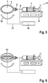
- Figures 5 to 7 show an electro-spinning process for depositing fibers on the support or workpiece. Specifically, a coated support obtained in a dip coating process according to figures 1 to 4 is used for application of fibers.
- Fig. 5 shows an electro-spinning device 6 comprising a pump 8 and syringe 7 for application of the fiber precursor, typically a solution of the comb polymer in organic solvent.
- the needle 9 of the syringe is an electrode and the other electrode can be under or in the support 1. Both electrodes are connected to a voltage source 10 by connection 11, which induces an electric field between needle 9 and support 1, thereby mediating formation of fibers 5 and deposition on the surface of support 1.
- the support can be moved, for example rotated, along direction 12, for achieving a uniform fiber distribution on the surface at least along the equatorial region of the implant.
- the support can be conductive and connected to the electrospinning device.
- Fig. 6 shows an internal view of the support with a double ring type collector electrode 13. This electrode type support provides uniform deposition of the fibers and orientation of the fibers, preferably in the equatorial region of the implant.
- Fig. 7 shows embodiments of circular electrodes for obtaining fiber orientation as parallel disks ( Fig. 7a ) or rings with connections to the center electrode contact ( Fig. 7b ).
- a subsequent pre-curing step should then be applied to ensure sufficient fixation of the fibers on the under-laying system and to avoid movement of the fibers in the following processing steps.
- the coating and spinning process of Figs. 1 to 7 can be repeated to obtain an outer shell and implant with multiple fiber layers embedded in a silicone matrix. The amount and direction of fibers in each layer can be adjusted to the desired strength and structure of the overall implant.
- the process can be terminated with a final curing step.
- the outer shell or implant surface can be structured, for example with salt crystals.
- Addition of a final silicone layer according the above describe technique ( Fig. 1 to 4 ) is a prerequisite for a final structuring step of the surface.
- the liquid silicone layer just brought on the fibers is procured and then covered with salt (NaCI) of a predetermined particle size, for example by trickling and/ or rolling on a salt covered plate. This is followed by a final curing typically at 120°C for typically several hours up to 20 h and subsequent washing off the soluble salt with water.
- the negative imprint of the salt crystals remains engraved on the surface.
- standard techniques to fill the implants and placing and sealing with patches can be applied.
- the electrospinning process or certain steps thereof can be controlled and/or executed electronically.
- the production process may comprise rotation of the support in a silicone bath and fiber-spinning on the surface at the same time or sequentially. When proceeding accordingly, a uniform composite is obtainable and the overall process is less complicated.
- the silicone matrix may comprise additional layers.
- one of the layers could be followed by a diffusion inhibition layer, for example by deposition of TiO 2 . It has been shown in the art that such a layer may inhibit diffusion of low molecular weight compounds in the matrix.
- the silicone matrix may comprise typical silicone elastomer compounds, such as derivatized silicone, for example with phenyl or fluorine groups. Such silicone derivatives can reduce diffusion of low molecular weight components in the silicone matrix.
- only portions of the layers of a laminate are crosslinked to each other.
- sections without crosslinking connection can be obtained when locally applying separation agents, or locally curing the emerging workpiece.
- Such a structure may inhibit growth of cracks within the implant.
- Another subject of the invention is the use of a fiber reinforced silicone for preparing a breast implant or the outer shell of a breast implant, wherein the fiber reinforced silicone is defined as above. Described herein is the use is for stabilizing the breast implant and/or improving the resilience of the breast implant. Described herein is the use is for preventing damages, especially ruptures and cracks, of the implant. Further described herein is also the use of fibers for reinforcing an outer shell or silicone breast implant, wherein the fibers are defined as above. Further described herein is also a fiber reinforced silicone as described above for use in surgery and/or in therapy. Preferably, the use is for breast reconstruction and/or breast augmentation, wherein the fiber reinforced silicone is defined as above. Described herein is that the fiber reinforced silicone is used as an implant or part of an implant.
- a breast implant or of an outer shell of a breast implant of the invention in surgery and/or in therapy, preferably for breast reconstruction and/or breast augmentation.
- a breast implant which has a high stability and resistance to damages, especially cracks and ruptures.
- the likelihood of damages can be significantly decreased when known silicone materials are reinforced with comb polymer fibers.
- the structure and stability can be adapted to the specific requirements of breast implants.
- silicone implants can be specifically and locally reinforced at desired positions, especially at sites prone to ruptures. Stabilization can also be achieved by orienting the fibers.
- the fibers have a good compatibility with and adhesion to the silicone matrix.
- the materials also have a good biocompatibility and high safety as required for breast implants. In view of the good stability, biocompatibility and safety and, the long-term stability can be expected to be high.
- crystal fractions comprising crystals of about ⁇ 63 ⁇ m (up to >0 ⁇ m), >63 ⁇ m (up to 100 ⁇ m), >100 ⁇ m (up to 150 ⁇ m), >150 ⁇ m (up to 250 ⁇ m) and >250 ⁇ m (up to 500 ⁇ m) and >500 ⁇ m.
- the liquid silicone rubber (trademark Elastosil LR 3003/30, available from Wacker Chemie AG, DE) has a high tear strength and exceeds the required 450 % minimum strain at break for mammary implants according to ISO 14607:2009. Additionally it has the same Shore Hardness (Type A) and a similar tear strength as addition cured silicone dispersion available under the trademark MED-6400 of NuSil Technology LLC, US, used for manufacturing of mammary implant shells by the former company Poly Implant Pro réelle.
- Components A and B of Elastosil LR 3003/30 were weighted in ratio 1:1 and mixed at 1000 rpm for 5 min by a SAC 150 SP speed mixer (Hauschild & Co. KG). The ratio of 1:1 was kept with a resolution of 1 mass %.
- the curable LSR blend is exposed to an under pressure of 0.4 mbar in a desiccator for 20 min. This was followed by mixing the blend for another 5 min at 1000 rpm and evacuating for 15 min at 0.4 mbar. Air removal is important, because otherwise the mechanical values such as ⁇ 0 and m can be decreased.
- LSR test stripes of a thickness of 0.50 mm; 0.75 mm and 1.00 mm were made by casting the curable blend into a milled PTFE trough mould. The casting was fastened by spreading the LSR with a doctor blade. At first the material was spread in greater thickness than the final stripe. Then dispersed air is drawn to the surface through under pressure of 0.4 mbar for 15 min. In a second step the bubble containing surplus of LSR at the surface was removed with a doctor blade. Thereby the withdrawal speed of the doctor blade was 5 +/- 2.5 mm/s. If 10 min at 0.4 mbar caused yet again air bubbles at the surface, more LSR was added and the casting procedure was repeated.
- a pre-cut piece of nanofiber mat was gently placed on top of the silicone layer and completely wetted.
- the system was repeatedly placed under vacuum to remove air. Additional silicone was placed on top of the fiber mat to ensure complete coverage of the fibers and uniform wetting.
- the system was placed in an air ventilated oven and allowed to cure for 20 h at 120 °C.
- the surfaces of homogeneous LSR prepared according to the examples above were textured with salt crystal fractions obtained by sieving according to example 1. From a height of 4 +/- 3 cm, a salt fraction prepared was trickled on the prepared surface and then distributed by tilting and shaking. Particle impact and weight as well as surface tension and deformation were responsible for the degree of particle sinking in.
- the outer (last) layer is additionally brought in contact with salt or sugar or other soluble substances, preferably water soluble solid substances. Therefore it is possible in a subsequent step to wash out the above describe salt, sugar or other dissolvable substance to achieve a desired surface structure.
- the applied solvent should not dissolve or substantially swell the LSR material.
- the specimens were cured at typically 120°C for up to 20 h.
- the mean surface roughness R z was determined according to DIN ISO 4287 for a series of textured silicone products obtained according to the examples above without reinforcing fibers. To achieve comparable information about the dimensions of the surface texture generated, the surface roughness was investigated. According to DIN EN ISO 4287 the mean surface roughness R z was determined. Therefore images of the textured surface were taken with a 3D laser scanning microscope (Keyance VK-9700). For determination of the R z values, the sampling length and the filter parameters were selected according DIN EN ISO 4288 and DIN EN ISO 3274, respectively. The results with mean values and standard deviation of the six surface textures are summarized in table 1 below. The mean value and standard deviation was obtained from five measurements each.
- the average lateral distance (medium (dx)) between indentations on the surface was determined graphically from microscopic images of cross sectional samples.
- a baseline x was defined parallel to the surface with a y coordinate perpendicular to the surface. The lowest positions in all indentations are marked on the x baseline. Distances dx between adjacent indentations on the x axis were calculated.
- the median (dx) was determined as 420,9 ⁇ m for the >500 ⁇ m sample, 283,9 ⁇ m for the >250 ⁇ m sample, 211.1 ⁇ m for the >150 ⁇ m sample, 149.4 ⁇ m for the >100 ⁇ m sample, 75.3 ⁇ m for the >63 ⁇ m sample and 47.7 ⁇ m for the ⁇ 63 ⁇ m sample.
- the mechanical properties were determined by tensile testing. Three stripes textured with salt particles of each fraction were produced according to the examples above, but without incorporation of fibers. This was done for each of the thicknesses 0.50 mm, 0.75 mm and 1.00 mm.
- Ten dumbbell specimens shaped according to DIN 53504 type S3 were punched out of each stripe. They were tested in a Zwick/Roell Frank-811110TM universal testing machine according to DIN 53504, but with an elongation speed of 20 mm/min instead of 200 mm/min.
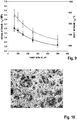
- the mesh width is used in the following. The effect of varying the mesh size on stress at break and strain at break is shown in Figure 9 .
- the median of stress at break could be increased by more than 85% from 2,17 MPa (IQR: 0,58 MPa) to 4,04 MPa (IQR: 0,52 MPa).
- the median of strain at break at the same time could be raise by over 30% from 656,56% (IQR: 81,96 %) to 865,57% (IQR: 149,41 %).
- Reducing the size of the salt particles by using sieves with smaller mesh size improves the stress at break and the strain at break simultaneously. Smaller particles cause smaller indentions on the surface and thereby cause lesser deterioration of the mechanical properties.
- Fig. 8 The resilience of products obtained as described above was examined by determining parameters ⁇ 0 and m and graphical evaluation in a Weibull plot according to the method described in Schubert et al., 2013.
- the results and values for conventional silicone implants are summarized in Fig. 8 .
- a series of textured silicone stripes without nanofibers was examined, wherein the average depths of indentations and average distances between indentations were decreased by applying smaller sized salt fractions from >500 ⁇ m to ⁇ 63 ⁇ m according to example 6 above.
- the open squares in Fig. 8 indicate the general improvement of resilience by modifying the implant shell structure from rough to smaller microstructures to smooth.
- silicone stripes were prepared according to the examples with and without nanofibers ( Fig. 8 , black squares).
- the shift along the arrow demonstrates the improvement by adding the fibers.
- the results show that by inclusion of fibers into the silicone matrix, the stability parameters can be shifted into a region which is highly advantageous for use of breast implants and long-term stability.
- a fine microstructure can impart additional stability to the implant.
Landscapes
- Chemical & Material Sciences (AREA)
- Health & Medical Sciences (AREA)
- Engineering & Computer Science (AREA)
- Medicinal Chemistry (AREA)
- Chemical Kinetics & Catalysis (AREA)
- Textile Engineering (AREA)
- Materials Engineering (AREA)
- General Health & Medical Sciences (AREA)
- Dermatology (AREA)
- Veterinary Medicine (AREA)
- Oral & Maxillofacial Surgery (AREA)
- Transplantation (AREA)
- Epidemiology (AREA)
- Life Sciences & Earth Sciences (AREA)
- Animal Behavior & Ethology (AREA)
- Public Health (AREA)
- Polymers & Plastics (AREA)
- Organic Chemistry (AREA)
- Composite Materials (AREA)
- Mechanical Engineering (AREA)
- Dispersion Chemistry (AREA)
- General Chemical & Material Sciences (AREA)
- Manufacturing & Machinery (AREA)
- Prostheses (AREA)
- Materials For Medical Uses (AREA)
Claims (13)
- Außenhülle eines Brustimplantats, wobei die Außenhülle ein faserverstärktes Silicon umfasst, umfassend(A) eine Siliconmatrix und(B) in die Siliconmatrix eingebettete Fasern,wobei die Fasern ein Kammpolymer mit einem Grundpolymer und Seitenketten umfassen, wobei das Grundpolymer ein organisches Polymer ist und die Seitenketten Polysiloxane umfassen.
- Außenhülle eines Brustimplantats nach Anspruch 1, wobei die Polysiloxanseitenketten mit dem Grundpolymer über Esterbindungen, Amidbindungen oder Etherbindungen verknüpft sind.
- Außenhülle eines Brustimplantats nach wenigstens einem der vorhergehenden Ansprüche, wobei das Kammpolymer umfassta) wenigstens eine Struktureinheit A
 R1 unabhängig voneinander für H oder CH3 steht;R2 unabhängig voneinander für eine Estergruppe -CO-O- , eine Amidgruppe -CO-NH- , eine Ethergruppe -O- oder keine Gruppe (leer) steht,R3 unabhängig voneinander für -R7-Y- steht, wobei R7 eine C1 - C6 Alkylengruppe ist, insbesondere Methylen, Ethylen oder Propylen, und Y entweder keine Gruppe (leer) oder O ist,R4 unabhängig voneinander für C1 - C4 Alkyl steht, bevorzugt für Methyl oder Ethyl,R5 unabhängig voneinander für C1 - C18 Alkyl steht, bevorzugt für C1 - C6 Alkyl,n unabhängig voneinander ein Wert zwischen 5 und 2000 ist, bevorzugt zwischen 20 und 1000, undb) wenigstens eine Struktureinheit B
 R1 unabhängig voneinander für H oder CH3 steht;R2 unabhängig voneinander für H oder CH3 steht, bevorzugt für H,R3 unabhängig voneinander für H oder CH3 steht, bevorzugt für H,R4 unabhängig voneinander für H, -CN, -COO-R6, -O-R6, -CO-N-R6 oder -R6 steht, wobei R6 ein C1 - C8 Alkyl ist, bevorzugt Methyl oder Ethyl.
 - Außenhülle eines Brustimplantats nach wenigstens einem der vorhergehenden Ansprüche, wobei die Fasern elektrogesponnen sind.
- Außenhülle eines Brustimplantats nach wenigstens einem der vorhergehenden Ansprüche, wobei die Fasern orientiert sind.
- Außenhülle eines Brustimplantats nach Anspruch 5, wobei wenigstens ein Teil der orientierten Fasern den Äquatorialbereich und/oder die Äquatorialebene des Implantats kreuzen.
- Außenhülle eines Brustimplantats nach wenigstens einem der vorhergehenden Ansprüche, wobei die Oberfläche des faserverstärkten Silicons texturiert ist, wobei die Textur bevorzugt in einem Verfahren erhalten wird, das ein Modifizieren der Oberfläche mit fraktionierten Kristallen umfasst, und/oder wobei die Oberflächenrauheit Rz bevorzugt im Bereich von 10 µm bis 150 µm liegt, und/oder wobei der durchschnittliche seitliche Abstand (Median (dx)) zwischen Vertiefungen auf der Oberfläche zwischen 45 µm und 210 µm beträgt.
- Außenhülle eines Brustimplantats nach wenigstens einem der vorhergehenden Ansprüche, wobei das faserverstärkte Silicon ein Laminat ist, das wenigstens zwei Faserschichten umfasst.
- Brustimplantat, umfassend eine Außenhülle nach wenigstens einem der vorhergehenden Ansprüche und einen Kern.
- Verfahren zur Herstellung einer Außenhülle oder eines Brustimplantats nach wenigstens einem der Ansprüche 1 bis 9, wobei die Herstellung des faserverstärkten Silicons Tauchbeschichten und/oder Elektrospinnen umfasst.
- Verfahren zur Herstellung einer Außenhülle oder eines Brustimplantats nach einem der Ansprüche 1 bis 9, umfassend die Schritte:(a) Bereitstellen eines Trägers und einer Lösung des Kammpolymers,(b) Spinnen der Lösung, um Fasern des Polymers zu erhalten, bevorzugt durch Elektrospinnen,(c) Ablegen von Fasern des Kammpolymers auf dem Träger,(d) Imprägnieren der Fasern mit einem flüssigen Silicon, bevorzugt durch Tauchbeschichten,(e) Härten des Produkts des Schritts (d), wodurch ein faserverstärktes Silicon erhalten wird, und(f) optionales Wiederholen der Schritte (a) bis (e) wenigstens einmal, wobei das im Schritt (e) erhaltene faserverstärkte Silicon als der Träger verwendet wird.
- Verfahren nach einem der Ansprüche 10 oder 11, wobei die Fasern durch Elektrospinnen orientiert werden, bevorzugt durch eine Elektrode in dem Träger.
- Verwendung eines faserverstärkten Silicons zur Herstellung eines Brustimplantats oder der Außenhülle eines Brustimplantats nach einem der Ansprüche 1 bis 9, wobei das faserverstärkte Silicon umfasst(A) eine Siliconmatrix und(B) in die Siliconmatrix eingebettete Fasern,wobei die Fasern ein Kammpolymer mit einem Grundpolymer und Seitenketten umfassen, wobei das Grundpolymer ein organisches Polymer ist und die Seitenketten Polysiloxan umfassen.
Applications Claiming Priority (2)
| Application Number | Priority Date | Filing Date | Title |
|---|---|---|---|
| EP15197017.5A EP3173104A1 (de) | 2015-11-30 | 2015-11-30 | Silikonbrustimplantat mit verstärkungsfasern |
| PCT/EP2016/078990 WO2017093181A1 (en) | 2015-11-30 | 2016-11-28 | Silicone breast implant with reinforcing fibers |
Publications (2)
| Publication Number | Publication Date |
|---|---|
| EP3383445A1 EP3383445A1 (de) | 2018-10-10 |
| EP3383445B1 true EP3383445B1 (de) | 2020-04-22 |
Family
ID=54782483
Family Applications (2)
| Application Number | Title | Priority Date | Filing Date |
|---|---|---|---|
| EP15197017.5A Withdrawn EP3173104A1 (de) | 2015-11-30 | 2015-11-30 | Silikonbrustimplantat mit verstärkungsfasern |
| EP16806012.7A Active EP3383445B1 (de) | 2015-11-30 | 2016-11-28 | Silikonbrustimplantat mit verstärkungsfasern |
Family Applications Before (1)
| Application Number | Title | Priority Date | Filing Date |
|---|---|---|---|
| EP15197017.5A Withdrawn EP3173104A1 (de) | 2015-11-30 | 2015-11-30 | Silikonbrustimplantat mit verstärkungsfasern |
Country Status (3)
| Country | Link |
|---|---|
| US (1) | US10675383B2 (de) |
| EP (2) | EP3173104A1 (de) |
| WO (1) | WO2017093181A1 (de) |
Families Citing this family (1)
| Publication number | Priority date | Publication date | Assignee | Title |
|---|---|---|---|---|
| EP3600463B1 (de) | 2017-03-23 | 2022-03-02 | Council of Scientific and Industrial Research | Verfahren zur beschichtung eines biomedizinischen implantats mit einem biokompatiblen polymer und biomedizinisches implantat daraus |
Family Cites Families (2)
| Publication number | Priority date | Publication date | Assignee | Title |
|---|---|---|---|---|
| US5053048A (en) * | 1988-09-22 | 1991-10-01 | Cordis Corporation | Thromboresistant coating |
| US5376117A (en) | 1991-10-25 | 1994-12-27 | Corvita Corporation | Breast prostheses |
-
2015
- 2015-11-30 EP EP15197017.5A patent/EP3173104A1/de not_active Withdrawn
-
2016
- 2016-11-28 EP EP16806012.7A patent/EP3383445B1/de active Active
- 2016-11-28 WO PCT/EP2016/078990 patent/WO2017093181A1/en not_active Ceased
- 2016-11-28 US US15/779,577 patent/US10675383B2/en not_active Expired - Fee Related
Non-Patent Citations (1)
| Title |
|---|
| None * |
Also Published As
| Publication number | Publication date |
|---|---|
| WO2017093181A1 (en) | 2017-06-08 |
| US10675383B2 (en) | 2020-06-09 |
| EP3383445A1 (de) | 2018-10-10 |
| EP3173104A1 (de) | 2017-05-31 |
| US20190262506A1 (en) | 2019-08-29 |
Similar Documents
| Publication | Publication Date | Title |
|---|---|---|
| KR101435888B1 (ko) | 히알루론산을 이용한 생분해성 마이크로니들 제조방법 | |
| Hu et al. | Electrospinning of poly (glycerol sebacate)-based nanofibers for nerve tissue engineering | |
| KR101861390B1 (ko) | 다공성 물질, 이의 제조 방법 및 그의 용도 | |
| Ren et al. | Electrospun PCL/gelatin composite nanofiber structures for effective guided bone regeneration membranes | |
| RU2583888C9 (ru) | Легкий материал грудного имплантата | |
| US20160355951A1 (en) | Core-sheath fibers and methods of making and using same | |
| WO2014143866A1 (en) | Core-sheath fibers and methods of making and using same | |
| WO2012175965A2 (en) | Polymeric materials | |
| KR102404093B1 (ko) | 중공형 다공성 미립구를 포함하는 피부 조직 재생 또는 피부 조직 볼륨 증진 주사용 조성물 | |
| KR102475289B1 (ko) | 임플란트로서 사용하기 위한, 고막 천공의 치료를 위한, 및 세포 배양을 위한 구조화된 코팅을 갖는 장치 | |
| EP3383445B1 (de) | Silikonbrustimplantat mit verstärkungsfasern | |
| WO2016195119A1 (ja) | マイクロニードル及びマイクロアレイ並びにその製造方法 | |
| Huang et al. | Nanostructured interfaces with RGD arrays to control cell–matrix interaction | |
| JP2023519897A (ja) | 生体適合性多孔質材料及び製造方法並びに使用方法 | |
| EP3641841A1 (de) | Aus der selbstmontage abgeleitete co-kontinuierliche materialien für biomedizinische vorrichtungen | |
| JP2023037496A (ja) | 薬剤送達デバイスおよびその製造方法 | |
| WO2019182099A1 (ja) | 糖反応性複合ゲル組成物、その製造方法、前記糖反応性複合ゲル組成物を含むインスリン送達マイクロニードルおよびその製造方法 | |
| CN114938627A (zh) | 用于粗糙表面的粘附体系 | |
| Kim et al. | Preparation of topographically modified poly (L-lactic acid)-b-Poly (ɛ-caprolactone)-b-poly (L-lactic acid) tri-block copolymer film surfaces and its blood compatibility | |
| Lunghi et al. | Fabrication and characterization of bioresorbable, electroactive and highly regular nanomodulated cell interfaces | |
| Karabanova et al. | Gradient semi-interpenetrating polymer networks based on polyurethane and poly (2-hydroxyethyl methacrylate) for biomedical applications | |
| ITPI20070089A1 (it) | Sviluppo di protesi mammarie innovative lisce e testurizzate rivestite con materiali altamente biocompatibili | |
| Zhang et al. | A nano-fibrous platform of copolymer patterned surfaces for controlled cell alignment | |
| WO2024243575A1 (en) | Stretchable microneedle electrode arrays and gel-assisted patterning of three-dimensional structures | |
| Kil et al. | Dextran as a fast resorbable and mechanically stiff coating for flexible neural probes |
Legal Events
| Date | Code | Title | Description |
|---|---|---|---|
| STAA | Information on the status of an ep patent application or granted ep patent |
Free format text: STATUS: UNKNOWN |
|
| STAA | Information on the status of an ep patent application or granted ep patent |
Free format text: STATUS: THE INTERNATIONAL PUBLICATION HAS BEEN MADE |
|
| PUAI | Public reference made under article 153(3) epc to a published international application that has entered the european phase |
Free format text: ORIGINAL CODE: 0009012 |
|
| STAA | Information on the status of an ep patent application or granted ep patent |
Free format text: STATUS: REQUEST FOR EXAMINATION WAS MADE |
|
| 17P | Request for examination filed |
Effective date: 20180608 |
|
| AK | Designated contracting states |
Kind code of ref document: A1 Designated state(s): AL AT BE BG CH CY CZ DE DK EE ES FI FR GB GR HR HU IE IS IT LI LT LU LV MC MK MT NL NO PL PT RO RS SE SI SK SM TR |
|
| AX | Request for extension of the european patent |
Extension state: BA ME |
|
| DAV | Request for validation of the european patent (deleted) | ||
| DAX | Request for extension of the european patent (deleted) | ||
| STAA | Information on the status of an ep patent application or granted ep patent |
Free format text: STATUS: EXAMINATION IS IN PROGRESS |
|
| 17Q | First examination report despatched |
Effective date: 20190618 |
|
| GRAP | Despatch of communication of intention to grant a patent |
Free format text: ORIGINAL CODE: EPIDOSNIGR1 |
|
| STAA | Information on the status of an ep patent application or granted ep patent |
Free format text: STATUS: GRANT OF PATENT IS INTENDED |
|
| INTG | Intention to grant announced |
Effective date: 20191121 |
|
| GRAS | Grant fee paid |
Free format text: ORIGINAL CODE: EPIDOSNIGR3 |
|
| GRAA | (expected) grant |
Free format text: ORIGINAL CODE: 0009210 |
|
| STAA | Information on the status of an ep patent application or granted ep patent |
Free format text: STATUS: THE PATENT HAS BEEN GRANTED |
|
| AK | Designated contracting states |
Kind code of ref document: B1 Designated state(s): AL AT BE BG CH CY CZ DE DK EE ES FI FR GB GR HR HU IE IS IT LI LT LU LV MC MK MT NL NO PL PT RO RS SE SI SK SM TR |
|
| REG | Reference to a national code |
Ref country code: CH Ref legal event code: EP |
|
| REG | Reference to a national code |
Ref country code: IE Ref legal event code: FG4D |
|
| REG | Reference to a national code |
Ref country code: DE Ref legal event code: R096 Ref document number: 602016034696 Country of ref document: DE |
|
| REG | Reference to a national code |
Ref country code: AT Ref legal event code: REF Ref document number: 1259220 Country of ref document: AT Kind code of ref document: T Effective date: 20200515 |
|
| REG | Reference to a national code |
Ref country code: LT Ref legal event code: MG4D |
|
| REG | Reference to a national code |
Ref country code: NL Ref legal event code: MP Effective date: 20200422 |
|
| PG25 | Lapsed in a contracting state [announced via postgrant information from national office to epo] |
Ref country code: IS Free format text: LAPSE BECAUSE OF FAILURE TO SUBMIT A TRANSLATION OF THE DESCRIPTION OR TO PAY THE FEE WITHIN THE PRESCRIBED TIME-LIMIT Effective date: 20200822 Ref country code: SE Free format text: LAPSE BECAUSE OF FAILURE TO SUBMIT A TRANSLATION OF THE DESCRIPTION OR TO PAY THE FEE WITHIN THE PRESCRIBED TIME-LIMIT Effective date: 20200422 Ref country code: GR Free format text: LAPSE BECAUSE OF FAILURE TO SUBMIT A TRANSLATION OF THE DESCRIPTION OR TO PAY THE FEE WITHIN THE PRESCRIBED TIME-LIMIT Effective date: 20200723 Ref country code: LT Free format text: LAPSE BECAUSE OF FAILURE TO SUBMIT A TRANSLATION OF THE DESCRIPTION OR TO PAY THE FEE WITHIN THE PRESCRIBED TIME-LIMIT Effective date: 20200422 Ref country code: PT Free format text: LAPSE BECAUSE OF FAILURE TO SUBMIT A TRANSLATION OF THE DESCRIPTION OR TO PAY THE FEE WITHIN THE PRESCRIBED TIME-LIMIT Effective date: 20200824 Ref country code: NO Free format text: LAPSE BECAUSE OF FAILURE TO SUBMIT A TRANSLATION OF THE DESCRIPTION OR TO PAY THE FEE WITHIN THE PRESCRIBED TIME-LIMIT Effective date: 20200722 Ref country code: FI Free format text: LAPSE BECAUSE OF FAILURE TO SUBMIT A TRANSLATION OF THE DESCRIPTION OR TO PAY THE FEE WITHIN THE PRESCRIBED TIME-LIMIT Effective date: 20200422 Ref country code: NL Free format text: LAPSE BECAUSE OF FAILURE TO SUBMIT A TRANSLATION OF THE DESCRIPTION OR TO PAY THE FEE WITHIN THE PRESCRIBED TIME-LIMIT Effective date: 20200422 |
|
| REG | Reference to a national code |
Ref country code: AT Ref legal event code: MK05 Ref document number: 1259220 Country of ref document: AT Kind code of ref document: T Effective date: 20200422 |
|
| PG25 | Lapsed in a contracting state [announced via postgrant information from national office to epo] |
Ref country code: HR Free format text: LAPSE BECAUSE OF FAILURE TO SUBMIT A TRANSLATION OF THE DESCRIPTION OR TO PAY THE FEE WITHIN THE PRESCRIBED TIME-LIMIT Effective date: 20200422 Ref country code: RS Free format text: LAPSE BECAUSE OF FAILURE TO SUBMIT A TRANSLATION OF THE DESCRIPTION OR TO PAY THE FEE WITHIN THE PRESCRIBED TIME-LIMIT Effective date: 20200422 Ref country code: LV Free format text: LAPSE BECAUSE OF FAILURE TO SUBMIT A TRANSLATION OF THE DESCRIPTION OR TO PAY THE FEE WITHIN THE PRESCRIBED TIME-LIMIT Effective date: 20200422 Ref country code: BG Free format text: LAPSE BECAUSE OF FAILURE TO SUBMIT A TRANSLATION OF THE DESCRIPTION OR TO PAY THE FEE WITHIN THE PRESCRIBED TIME-LIMIT Effective date: 20200722 |
|
| PG25 | Lapsed in a contracting state [announced via postgrant information from national office to epo] |
Ref country code: AL Free format text: LAPSE BECAUSE OF FAILURE TO SUBMIT A TRANSLATION OF THE DESCRIPTION OR TO PAY THE FEE WITHIN THE PRESCRIBED TIME-LIMIT Effective date: 20200422 |
|
| REG | Reference to a national code |
Ref country code: DE Ref legal event code: R097 Ref document number: 602016034696 Country of ref document: DE |
|
| PG25 | Lapsed in a contracting state [announced via postgrant information from national office to epo] |
Ref country code: EE Free format text: LAPSE BECAUSE OF FAILURE TO SUBMIT A TRANSLATION OF THE DESCRIPTION OR TO PAY THE FEE WITHIN THE PRESCRIBED TIME-LIMIT Effective date: 20200422 Ref country code: SM Free format text: LAPSE BECAUSE OF FAILURE TO SUBMIT A TRANSLATION OF THE DESCRIPTION OR TO PAY THE FEE WITHIN THE PRESCRIBED TIME-LIMIT Effective date: 20200422 Ref country code: DK Free format text: LAPSE BECAUSE OF FAILURE TO SUBMIT A TRANSLATION OF THE DESCRIPTION OR TO PAY THE FEE WITHIN THE PRESCRIBED TIME-LIMIT Effective date: 20200422 Ref country code: CZ Free format text: LAPSE BECAUSE OF FAILURE TO SUBMIT A TRANSLATION OF THE DESCRIPTION OR TO PAY THE FEE WITHIN THE PRESCRIBED TIME-LIMIT Effective date: 20200422 Ref country code: ES Free format text: LAPSE BECAUSE OF FAILURE TO SUBMIT A TRANSLATION OF THE DESCRIPTION OR TO PAY THE FEE WITHIN THE PRESCRIBED TIME-LIMIT Effective date: 20200422 Ref country code: IT Free format text: LAPSE BECAUSE OF FAILURE TO SUBMIT A TRANSLATION OF THE DESCRIPTION OR TO PAY THE FEE WITHIN THE PRESCRIBED TIME-LIMIT Effective date: 20200422 Ref country code: RO Free format text: LAPSE BECAUSE OF FAILURE TO SUBMIT A TRANSLATION OF THE DESCRIPTION OR TO PAY THE FEE WITHIN THE PRESCRIBED TIME-LIMIT Effective date: 20200422 Ref country code: AT Free format text: LAPSE BECAUSE OF FAILURE TO SUBMIT A TRANSLATION OF THE DESCRIPTION OR TO PAY THE FEE WITHIN THE PRESCRIBED TIME-LIMIT Effective date: 20200422 |
|
| PG25 | Lapsed in a contracting state [announced via postgrant information from national office to epo] |
Ref country code: PL Free format text: LAPSE BECAUSE OF FAILURE TO SUBMIT A TRANSLATION OF THE DESCRIPTION OR TO PAY THE FEE WITHIN THE PRESCRIBED TIME-LIMIT Effective date: 20200422 Ref country code: SK Free format text: LAPSE BECAUSE OF FAILURE TO SUBMIT A TRANSLATION OF THE DESCRIPTION OR TO PAY THE FEE WITHIN THE PRESCRIBED TIME-LIMIT Effective date: 20200422 |
|
| PLBE | No opposition filed within time limit |
Free format text: ORIGINAL CODE: 0009261 |
|
| STAA | Information on the status of an ep patent application or granted ep patent |
Free format text: STATUS: NO OPPOSITION FILED WITHIN TIME LIMIT |
|
| 26N | No opposition filed |
Effective date: 20210125 |
|
| PG25 | Lapsed in a contracting state [announced via postgrant information from national office to epo] |
Ref country code: SI Free format text: LAPSE BECAUSE OF FAILURE TO SUBMIT A TRANSLATION OF THE DESCRIPTION OR TO PAY THE FEE WITHIN THE PRESCRIBED TIME-LIMIT Effective date: 20200422 |
|
| PG25 | Lapsed in a contracting state [announced via postgrant information from national office to epo] |
Ref country code: MC Free format text: LAPSE BECAUSE OF FAILURE TO SUBMIT A TRANSLATION OF THE DESCRIPTION OR TO PAY THE FEE WITHIN THE PRESCRIBED TIME-LIMIT Effective date: 20200422 |
|
| REG | Reference to a national code |
Ref country code: CH Ref legal event code: PL |
|
| PG25 | Lapsed in a contracting state [announced via postgrant information from national office to epo] |
Ref country code: LU Free format text: LAPSE BECAUSE OF NON-PAYMENT OF DUE FEES Effective date: 20201128 |
|
| REG | Reference to a national code |
Ref country code: BE Ref legal event code: MM Effective date: 20201130 |
|
| PG25 | Lapsed in a contracting state [announced via postgrant information from national office to epo] |
Ref country code: CH Free format text: LAPSE BECAUSE OF NON-PAYMENT OF DUE FEES Effective date: 20201130 Ref country code: LI Free format text: LAPSE BECAUSE OF NON-PAYMENT OF DUE FEES Effective date: 20201130 |
|
| PG25 | Lapsed in a contracting state [announced via postgrant information from national office to epo] |
Ref country code: IE Free format text: LAPSE BECAUSE OF NON-PAYMENT OF DUE FEES Effective date: 20201128 |
|
| PGFP | Annual fee paid to national office [announced via postgrant information from national office to epo] |
Ref country code: DE Payment date: 20211109 Year of fee payment: 6 Ref country code: GB Payment date: 20211109 Year of fee payment: 6 Ref country code: FR Payment date: 20211109 Year of fee payment: 6 |
|
| PG25 | Lapsed in a contracting state [announced via postgrant information from national office to epo] |
Ref country code: TR Free format text: LAPSE BECAUSE OF FAILURE TO SUBMIT A TRANSLATION OF THE DESCRIPTION OR TO PAY THE FEE WITHIN THE PRESCRIBED TIME-LIMIT Effective date: 20200422 Ref country code: MT Free format text: LAPSE BECAUSE OF FAILURE TO SUBMIT A TRANSLATION OF THE DESCRIPTION OR TO PAY THE FEE WITHIN THE PRESCRIBED TIME-LIMIT Effective date: 20200422 Ref country code: CY Free format text: LAPSE BECAUSE OF FAILURE TO SUBMIT A TRANSLATION OF THE DESCRIPTION OR TO PAY THE FEE WITHIN THE PRESCRIBED TIME-LIMIT Effective date: 20200422 |
|
| PG25 | Lapsed in a contracting state [announced via postgrant information from national office to epo] |
Ref country code: MK Free format text: LAPSE BECAUSE OF FAILURE TO SUBMIT A TRANSLATION OF THE DESCRIPTION OR TO PAY THE FEE WITHIN THE PRESCRIBED TIME-LIMIT Effective date: 20200422 |
|
| PG25 | Lapsed in a contracting state [announced via postgrant information from national office to epo] |
Ref country code: BE Free format text: LAPSE BECAUSE OF NON-PAYMENT OF DUE FEES Effective date: 20201130 |
|
| REG | Reference to a national code |
Ref country code: DE Ref legal event code: R119 Ref document number: 602016034696 Country of ref document: DE |
|
| GBPC | Gb: european patent ceased through non-payment of renewal fee |
Effective date: 20221128 |
|
| PG25 | Lapsed in a contracting state [announced via postgrant information from national office to epo] |
Ref country code: GB Free format text: LAPSE BECAUSE OF NON-PAYMENT OF DUE FEES Effective date: 20221128 Ref country code: DE Free format text: LAPSE BECAUSE OF NON-PAYMENT OF DUE FEES Effective date: 20230601 |
|
| PG25 | Lapsed in a contracting state [announced via postgrant information from national office to epo] |
Ref country code: FR Free format text: LAPSE BECAUSE OF NON-PAYMENT OF DUE FEES Effective date: 20221130 |