EP3383274B1 - Radiological imaging device - Google Patents
Radiological imaging device Download PDFInfo
- Publication number
- EP3383274B1 EP3383274B1 EP16815646.1A EP16815646A EP3383274B1 EP 3383274 B1 EP3383274 B1 EP 3383274B1 EP 16815646 A EP16815646 A EP 16815646A EP 3383274 B1 EP3383274 B1 EP 3383274B1
- Authority
- EP
- European Patent Office
- Prior art keywords
- arched
- module
- mobile
- gantry
- imaging device
- Prior art date
- Legal status (The legal status is an assumption and is not a legal conclusion. Google has not performed a legal analysis and makes no representation as to the accuracy of the status listed.)
- Active
Links
Images

Classifications
-
- A—HUMAN NECESSITIES
- A61—MEDICAL OR VETERINARY SCIENCE; HYGIENE
- A61B—DIAGNOSIS; SURGERY; IDENTIFICATION
- A61B6/00—Apparatus or devices for radiation diagnosis; Apparatus or devices for radiation diagnosis combined with radiation therapy equipment
- A61B6/02—Arrangements for diagnosis sequentially in different planes; Stereoscopic radiation diagnosis
- A61B6/03—Computed tomography [CT]
- A61B6/032—Transmission computed tomography [CT]
- A61B6/035—Mechanical aspects of CT
-
- A—HUMAN NECESSITIES
- A61—MEDICAL OR VETERINARY SCIENCE; HYGIENE
- A61B—DIAGNOSIS; SURGERY; IDENTIFICATION
- A61B6/00—Apparatus or devices for radiation diagnosis; Apparatus or devices for radiation diagnosis combined with radiation therapy equipment
- A61B6/04—Positioning of patients; Tiltable beds or the like
- A61B6/0407—Supports, e.g. tables or beds, for the body or parts of the body
-
- A—HUMAN NECESSITIES
- A61—MEDICAL OR VETERINARY SCIENCE; HYGIENE
- A61B—DIAGNOSIS; SURGERY; IDENTIFICATION
- A61B6/00—Apparatus or devices for radiation diagnosis; Apparatus or devices for radiation diagnosis combined with radiation therapy equipment
- A61B6/10—Safety means specially adapted therefor
- A61B6/102—Protection against mechanical damage, e.g. anti-collision devices
-
- A—HUMAN NECESSITIES
- A61—MEDICAL OR VETERINARY SCIENCE; HYGIENE
- A61B—DIAGNOSIS; SURGERY; IDENTIFICATION
- A61B6/00—Apparatus or devices for radiation diagnosis; Apparatus or devices for radiation diagnosis combined with radiation therapy equipment
- A61B6/42—Arrangements for detecting radiation specially adapted for radiation diagnosis
- A61B6/4208—Arrangements for detecting radiation specially adapted for radiation diagnosis characterised by using a particular type of detector
- A61B6/4241—Arrangements for detecting radiation specially adapted for radiation diagnosis characterised by using a particular type of detector using energy resolving detectors, e.g. photon counting
-
- A—HUMAN NECESSITIES
- A61—MEDICAL OR VETERINARY SCIENCE; HYGIENE
- A61B—DIAGNOSIS; SURGERY; IDENTIFICATION
- A61B6/00—Apparatus or devices for radiation diagnosis; Apparatus or devices for radiation diagnosis combined with radiation therapy equipment
- A61B6/44—Constructional features of apparatus for radiation diagnosis
- A61B6/4405—Constructional features of apparatus for radiation diagnosis the apparatus being movable or portable, e.g. handheld or mounted on a trolley
-
- A—HUMAN NECESSITIES
- A61—MEDICAL OR VETERINARY SCIENCE; HYGIENE
- A61B—DIAGNOSIS; SURGERY; IDENTIFICATION
- A61B6/00—Apparatus or devices for radiation diagnosis; Apparatus or devices for radiation diagnosis combined with radiation therapy equipment
- A61B6/44—Constructional features of apparatus for radiation diagnosis
- A61B6/4429—Constructional features of apparatus for radiation diagnosis related to the mounting of source units and detector units
- A61B6/4435—Constructional features of apparatus for radiation diagnosis related to the mounting of source units and detector units the source unit and the detector unit being coupled by a rigid structure
- A61B6/4447—Tiltable gantries
Definitions
- the present invention relates to a radiological imaging device of the type as recited in claim 1.
- the invention relates to a device suitable to be used in the medical/veterinary sphere to obtain images of at least a portion of the internal anatomy of a patient, and thus to perform analyses, diagnoses or other assessments of said patient.
- This structure provides a bed on which the patient is placed, a control station suitable to control the operation of the device; a gantry, O-shaped, defining a cavity in which the portion to be analysed is inserted and suitable to perform the radiological imaging of the patient; and a support supporting the gantry and the bed and able to mutually translate the bed and gantry.
- an X-ray source a detector which receives the X-rays after they have passed through the bed, and the patient are positioned inside the gantry.
- the radiological device has a rotation member which, by rotating the entire gantry or only the source and detector around the patient, makes it possible to perform scans at different angles.
- a first important drawback is that the radiological imaging devices currently available are particularly bulky.
- the gantry having to contain the source, the detector and the rotation member, is particularly bulky. In fact, it has a diameter at least equal to 1.5 metres and is therefore unable to pass through doors or other accesses present in hospitals.
- the patient must be taken from the operating table, laid on a hospital bed, moved in the hospital to the room where the radiological imaging device is located, lifted again, and then laid on the bed of the device.
- radiological devices comprising a C-shaped gantry, said "C arm”, composed of a solid C-shaped arched body at the ends of which source and detector are integrally constrained; and a particular rotation member of the entire C arm.
- radiological imaging devices are able to make the source and detector rotate only by a limited angular amplitude of not more than 200°.
- radiological imaging devices are often designed for a single function, usually only fluoroscopy, and thus have lesser functional flexibility.
- the limited rotation does not allow the C arm devices to perform scanning from any angle.
- the technical purpose of the present invention is to devise a radiological imaging device able to substantially overcome the drawbacks mentioned above.
- one important aim of the invention is to obtain an imaging device which makes it possible to move the patient easily and, above all, eliminates or reduces the risks to the patient without detracting from the angular scanning amplitude.
- one important purpose of the invention is to provide a radiological imaging device which has reduced dimensions but nevertheless, makes it possible to perform scans of angular amplitude equal to at least 360°.
- the measures, values, shapes and geometric references (such as perpendicularity and parallelism), when used with words like “about” or other similar terms such as “approximately” or “substantially”, are to be understood as except for measurement errors or inaccuracies due to production and/or manufacturing errors and, above all, except for a slight divergence from the value, measure, shape or geometric reference which it is associated with.
- said terms, if associated with a value preferably indicate a divergence of not more than 10% of said value.
- processing refers to the action and/or a processes of a computer or calculation system which handles and/or processes data represented as physical, such as electronic magnitudes of logs of a computer system and/or memories of other data similarly represented such as physical quantities inside computer systems, logs or other information storage, transmission or display devices.
- reference numeral 1 globally denotes a radiological imaging device according to the invention.
- the radiological imaging device 1 is suitable for use in the medical field (human/veterinary) for performing radiological imaging of at least one portion of the internal anatomy of a patient.
- the radiological imaging device 1 is suitable for use in the medical field (human/veterinary) for performing X-rays, CAT scans, fluoroscopy and other radiological imaging examinations.
- the device 1 comprises a gantry 2 suitable to perform the X-ray imaging; and a control unit 1a suitable to manage the operation of the device 1 and, to be precise, at least the gantry 2.
- the gantry 2 defines an analysis area 2a suitable to contain at least a portion of the patient to be analysed and, appropriately, a circular extension trajectory 2b extending, and thus having its centre, on a central axis 2c.
- the circular extension trajectory 2b lies on a plane substantially perpendicular to the central axis 2c.
- the gantry 2 comprises a source 21 suitable to emit a radiation, preferably X-rays, defining a central propagation axis 21a preferably approximately perpendicular to the central axis 2c; a detector 22 suitable to receive the radiation after it has crossed the analysis area 2a and, therefore, the portion of the patient in analysis; and a casing 23 defining a volume for housing at least the source 21, the detector 22 and extending substantially along the circular extension trajectory 2b.
- a source 21 suitable to emit a radiation, preferably X-rays, defining a central propagation axis 21a preferably approximately perpendicular to the central axis 2c
- a detector 22 suitable to receive the radiation after it has crossed the analysis area 2a and, therefore, the portion of the patient in analysis
- a casing 23 defining a volume for housing at least the source 21, the detector 22 and extending substantially along the circular extension trajectory 2b.
- the source 21 comprises an X-ray emitter defining the central axis 21a and, optionally, a tilt-system suitable to rotate, appropriately, with respect to the casing 23, the X-ray emitter and, therefore, the propagation axis 21a, preferably around a tilt-axis approximately parallel to the central axis 2c and, more preferably, passing through the focal spot of the emitter so as to maintain approximately stationary the focal spot.
- the detector 22 comprises at least one sensor defining a surface sensitive to X-rays and suitable to selectively perform, appropriately on the basis of a command given by the operator, tomographies, fluoroscopies and/or X-rays. It consequently defines at least one sensitive surface suitable to detect the radiation and, in particular, substantially perpendicular to the axis of propagation 21a.
- the at least one sensor may comprise at least one between: a linear sensor and, preferably, two linear sensors defining sensitive surfaces substantially coplanar; a rectangular sensor, known as a flat panel, preferably suitable to vary the extension of the active sensitive surface; a direct photon count sensor; a dual energy sensor; a concavity sensor directed towards the central axis 2c; a variable geometry sensor: flat or concave.
- the detector 22 may further comprise at least one lateral and/or vertical movement apparatus and, in detail, at least one waver suitable to translate along a waving axis and a lifting system suitable to move the sensor along a lifting axis approximately perpendicular to the waving axis.
- the waver presents a slider connected to the sensor, a waving guide defining the waving axis and a motor, in detail electric, controlling the movement of the slider on the waving guide.
- the waving axis is substantially perpendicular to the central propagation axis 21a and to the central axis 2c.
- the lifting system comprises a linear actuator, preferably electric, suitable to move the sensor and, preferably, the waver along the lifting axis.
- the lifting axis is approximately parallel to the central axis of propagation 21a and substantially perpendicular to the central axis 2c.
- the casing 23 constitutes the outer body of the gantry 2 and consequently, defines the overall dimensions and, in particular, the angular extension of the gantry 2 and the trajectory 2b.
- the casing 23 and therefore the gantry 2 are of the telescopic type and, consequently, suitable to vary their angular extension along the extension trajectory 2b preferably defining at least a rest configuration and at least one working configuration for the gantry 2.
- the casing 23 and therefore the gantry 2 vary their angular extension and, therefore, the angular extension of the housing defined by the casing 23, keeping the source 21 and detector 22 inside said housing volume.
- the casing 23 and the gantry 2 are contracted and have a minimum angular extension. Consequently, the casing 23, the gantry 2 and therefore the circular extension trajectory 2b define an arc of circumference substantially centred on the axis 2c and having an angular extension approximately less than 260°. In detail, in the rest configuration the trajectory 2b has a minimum angular extension of angular amplitude approximately less than 210° and, in more detail, substantially equal to 190°.
- the casing 23 and the gantry 2 have a circular extension trajectory 2b having a greater angular extension than said minimum angular extension so as to at least partially surround at least a major portion of the analysis area 2a allowing the source 21 and the detector 22 to place themselves on opposite sides of the axis 2c and thus the area 2a.
- the gantry 2 defines a working configuration of maximum extension ( Figs. 1e , 4b ), in which the casing 23 and therefore the gantry 2 are approximately closed and present the circular extension trajectory 2b which presents an angular extension of 360° defining, accordingly, an O-shaped gantry 2 enclosing and, suitably, laterally delimiting the entire analysis area 2a.
- the gantry 2 passes from one configuration to the other keeping the source 21 and detector 22 always inside the housing volume regardless of the angular extension of the casing 23 and thus of the gantry 2 along the circular extension trajectory 2b, as more fully described below.
- the detector 22 can come out and protrude at least partially from the casing 23.
- the gantry 2 and, in particular, the casing 23 may present a through window which faces the analysis area 2a and allows the detector 22 to protrude from the casing 23 when translated along the lifting axis.
- the casing 23 comprises at least two substantially hollow modules so as to define the housing volume.
- the modules have a preferred extension trajectory substantially coinciding with the circular extension trajectory 2b, i.e. with the centre on the central axis 2c, and, advantageously, different cross-sections allowing for their mutual insertion/ overlapping.
- the casing 23 comprises at least one, preferably only one, bottom arched module 231 and at least one arched module mobile with respect to the bottom module 231 so as to vary the angular extension of the casing 23 and of the gantry and, thus, the housing volume.
- the casing 23 comprises a bottom arched module 231, a first mobile arched module 232a and a second mobile arched module 232b placed at the end of the bottom module 231 opposite the first module 232a and preferably substantially specular to said first module 232a.
- the mobile modules 232a and 232b are mobile in a dependent manner, i.e. simultaneously and with substantially the same speed and same direction of advancement along the trajectory 2b, and independently of each other.
- the arched modules 231, 232a and 232b have substantially the same barycentric extension axis preferably approximately coinciding with the circular extension trajectory 2b.
- the sum of the angular amplitudes of the modules 231, 232a and 232b is at least equal to 360°.
- said sum of the angular amplitudes of the modules 231, 232a and 232b is at least 370° so as to always have an overlap zone of the mobile modules 232a and 232b with the bottom module 231 suitable to give greater structural stability to the gantry 2.
- the bottom arched module 231 has an angular extension approximately less than 240° and, more particularly, substantially less than 210° and, even more particularly, substantially comprised between 190° and 160°.
- Each mobile arched module 232a and 232b has an angular extension smaller than the angular semi-extension of the bottom module 231 so that, when, the radiological imaging device is in the rest configuration, the mobile modules 232a and 232b are inside the bottom module 231 and spaced apart defining a free sector 231a of the bottom module 231.
- the mobile modules 232a and 232b preferably have mutually the same angular extension and the free sector 231a is appropriately placed in the middle of the bottom body 231, i.e. at the bisector of the angle of extension of the bottom body 231.
- each mobile arched module 232a and 232b has an angular extension approximately less than 140° and, preferably approximately less than 120° and, more preferably, substantially comprised between 90° and 60°.
- the mobile arched modules 232a and 232b have different cross-sections from that of the bottom arched module 231 so as to at least partially overlap the bottom module 231 and, advantageously, vary the extension of the part of the mobile module 232a and 232b overlapping the bottom module 231 during a change of configuration.
- the mobile arched modules 232a and 232b have a cross section less than that of the bottom module 231 so as to be housed inside it and, advantageously, vary the extension of the part of the mobile module 232a and 232b inside the arched bottom module 231 during a change of configuration.
- each arched mobile module 232a and 232b is totally overlapped and, to be precise, housed in the bottom module 231 so that the angular extension of the gantry 2 is substantially equal to that of the bottom module 231. More preferably, in the rest configuration the mobile arched modules 232a and 232b are completely housed in the arched bottom module 231.
- the angular extension of the gantry 2 is approximately equal to the angular extension of the bottom module 231 plus the angular extension of each portion of mobile arched module 232a and 232b protruding from the arched bottom module 231.
- the bottom module 23 having to contain inside it the mobile modules 232a and 232b, defines a portion of the housing volume with a cross-section substantially at least equal and in particular, greater than the cross-section of the mobile modules 232a and 232b. Consequently, the cross-sections of the portion of housing volume of the mobile modules 232a and 232b are substantially equal to each other and less than the cross-section of the portion of housing volume of the bottom module 231.
- the modules 231, 232a and 232b are identifiable in hollow, arched profiles.
- the gantry 2 comprises a movement apparatus 24 of at least the mobile arched modules 232a and/or 232b with respect to the bottom arched module 231.
- the movement apparatus 24 is suitable to move both the mobile modules 232a and 232b and the bottom module 231 allowing, in addition to said change of configuration, the source 21 and detector 22 to rotate around the analysis area 2a and, thus the central axis 2c defining a rotation of maximum amplitude at least equal to 360°.
- the apparatus 24 includes at least a bottom guide 241 integral with the arched bottom module 231 and defining a bottom movement trajectory 241a, at least one mobile guide 242 integral with the at least one arched mobile module and defining a mobile movement trajectory 242a, and at least one thrust assembly 243 suitable to engage at least one of the guides 241 and/or 242 controlling the rotation of the at least one corresponding arched module 231, 232a and 232b around the central axis 2c.
- the mobile guide 242 is integral with both mobile arched modules 232a and 232b. It is therefore divided into two sectors and comprises a first sector 242b integral with the first arched mobile module 232a and defining a first portion of the mobile trajectory 242a; and a second sector 242c integral with the second arched mobile module 232b and defining a second portion of the mobile trajectory 242a.
- the guides 241 and 242 are external to the housing volume and, therefore, to the casing 23. Accordingly, the mover 242 is also external to the housing volume and to the casing 23.
- the bottom guide 241 is made on at least one of the outer faces of the arched bottom module 231 preferably not facing the analysis area 2a. More preferably, it is made on at least one and, in particular, on only one of the outer faces of the arched bottom module 231 approximately perpendicular to the central axis 2c.
- the mobile guide 242 and, thus, the sectors 242b and 242c are made on at least one of the outer faces of the mobile arched modules 232a and 232b suitably not facing the analysis area 2a. Preferably, it is made on at least one and, in particular on only one of the external faces of the mobile arched modules 232a and 232b substantially perpendicular to the central axis 2c.
- the guides 241 and 242 are made on outer faces of the arched modules 231, 232a and 232b suitable to overlap each other when the mobile modules 232a and 232b are at least partially inside the bottom module 231.
- the guides 241 and 242 and the movement trajectories 241a and 242a are substantially circular and approximately concentric to the axis 2c.
- the mobile guide 242 and the mobile trajectory 242a are distinct from the bottom guide 241 and from the bottom trajectory 241a so that, when the arched mobile module 232a or 232b is moved with respect to the arched bottom module 231, i.e. there is a change of configuration of the gantry 2, the surfaces of the guides 241 and 242 and trajectories 241a and 242a slide reciprocally without touching and appropriately varying the angular extension of the mobile guide 242 overlapped on the bottom guide 241.
- the mobile guide 242 and, consequently, the mobile trajectory 242a are separate from the bottom guide 241 and from the bottom trajectory 241a by having a different radius, calculated with respect to the axis 2c or a different position along the central axis 2c, i.e. the lying planes of the trajectories 241a and 242a intersect the central axis 2c in two separate points.
- the mobile guide 242 and the mobile trajectory 242a have a different radius and, in particular smaller than that of the bottom guide 241 and of the bottom trajectory 241a.
- the angular amplitude of the mobile guide 242 and, to be precise, the individual sectors 242b and 242c, added to that of the bottom guide 241, may be approximately more than 360° so that the gantry 2 always has, even in the working configuration at maximum extension, at least one overlapping area between the guides 241 and 242, i.e. an area where both the mobile guide 242 and the bottom guide 241 are present so that the thrust unit 243 is simultaneously engageable to both of the guides 241 and 242.
- the sum of the angular extensions of the guides 241 and 242 and, therefore, of the movement trajectories 241a and 242a is substantially at least equal to 360° and, in more detail, to 380°.
- the bottom guide 241 has an angular extension approximately equal to that of the bottom module 231. In detail, it has approximately an angular extension approximately smaller than 240°, preferably 210° and, more preferably, substantially between 190° and 180°.
- the mobile guide 242 has an angular extension approximately less than 240°, preferably 210° and, more preferably, approximately comprised between 190° and 180°.
- each sector 242b and 242c has an angular extension equal to that of the respective mobile module 232a and 232b. More in detail, each sector 242b and 242c has an angular extension of less than 140° preferably than 120° and, more preferably, substantially between 100° and 85°.
- the thrust assembly 243 is external to the casing 23 and is suitable to engage, individually and/or simultaneously, the guides 241 and 242 controlling the movement of at least part of the arched modules 231, 232a and 232b.
- Fig. 3 it comprises at least a first engagement element 2431 to the bottom guide 241 suitable to control the rotation of at least the arched bottom module 231; at least one second engagement element 2432 to the mobile guide 242 suitable to control the rotation of at least one arched mobile module 232a or 232b; and, suitably, a support 2433 for said elements 2431 and 2432.
- the at least one first engagement element 2431 and/or the at least one second engagement element 2432 may respectively define a first engagement area 2431a and a second engagement area 2432a at least partially overlapping one another radially, i.e. along a first approximately radial direction, suitably a circular extension trajectory 2b, and having a suitable angular amplitude.
- Said radial overlap identifies the fact that the engagement areas 2431a and 2432a, if projected on one another in the radial direction, have a non-null overlap.
- Each engagement area 2431a and 2432a is identifiable in the surface of the element 2431 or 2432 suitable to come into contact with the respective guide 241 or 242.
- the thrust assembly 243 comprises several first engagement elements 2431 mutually angularly spaced along the circular extension trajectory 2b so as to engage to the bottom guide 241 in different points and, thus, have a broader first engagement area 2431a.
- the first engagement elements 2431 have a mutual angular distance and, therefore, an amplitude of the first engagement area 2431a substantially at least equal to 10° and, to be precise, substantially comprised between 10° and 30°.
- the first engagement element 2431 is identifiable in a toothed wheel, motorised, suitably electrically, and the bottom guide 241 is identifiable in a rack.
- the bottom guide 241 is substantially smooth and, suitably, the first element 2431 is identifiable in a friction wheel (i.e. suitably coated or made of rubber or other high friction material) motorised, preferably, electrically, i.e. a wheel suitable to engage to the bottom guide 241 and to exploit the friction force between the wheel and the bottom guide 241 to move the bottom module 231.
- the thrust assembly 243 comprises several second engagement elements 2432 mutually angularly spaced along the circular extension trajectory 2b so as to engage to the mobile guide 242 in different points and, thus, have a broader second engagement area 2432a.
- the second engagement elements 2432 have a mutual angular distance and, therefore, an amplitude of the second engagement area 2432a at least equal to 10° and, to be precise, substantially comprised between 10° and 30°.
- Each second engagement element 2432 is identifiable in at least one toothed wheel, motorised, suitably electrically, and the mobile guide 242 is identifiable in a rack.
- the mobile guide 242 is approximately smooth and, suitably, coated in rubber or other high friction material and the second element 2432 is a friction wheel, motorised, preferably electrically.
- the movement apparatus 24 comprises at least one through slot 244 made on the bottom module 231 and suitable to overlap the mobile guide 242 so as to appropriately put it into view through said bottom arched module 231 allowing an engagement between the second thrust means 2432, external to the casing 23, and the mobile guide 242 constrained to the mobile modules 232a and 232b, i.e. inside the casing 23.
- the movement apparatus 24 comprises a single through slot 244 having an angular extension substantially equal to that of the bottom arched module 231 and extending substantially along the second trajectory 242a.
- it comprises two through slots 244 ( Fig. 4b ) of which one having an angular extension approximately equal to the first sector 242b and the other having an angular extension approximately equal to the second sector 242c.
- the movement apparatus 24, to allow the modules 231, 232a and 232b to rotate mutually exclusively may comprise at least one between: a radial constraint suitable to prevent a relative radial motion between the thrust assembly 243 and guides 241 and 242; and an axial constraint suitable to prevent a relative axial motion between the thrust assembly 243 and the guides 241 and 242.
- the movement apparatus 24 comprises both said radial constraint and said axial constraint.
- the radial constraint shown in Fig. 3 , comprises at least a first abutment 251 suitable to engage to the bottom guide 241 on the opposite side to the first engagement element 2431; and at least a second abutment 252 suitable to engage the mobile guide 242 on the side opposite the second element 2432.
- the abutments 251 and 252 are identified in the wheels, preferably idle, toothed or friction.
- the axial constraint shown in Fig. 3 , comprises a first prominence 261 protruding radially from the bottom guide 241 and distal from the bottom module 231 so as to enclose the first engagement element 2431 between said first prominence 261 and the bottom module 231; and a second prominence 262 protruding radially from the mobile guide 242 and distal from the mobile module 232a and 232b and in particular from the bottom module 231 so as to enclose the first engagement element 2431 between said second prominence 262 and the bottom module 231.
- the gantry 2 comprises at least one lock, placed appropriately in the housing volume, suitable to selectively lock or prevent the relative sliding between said arched modules 231, 232a and 232b and, thus, to define a locked position in which it prevents the relative movement between the modules 231, 232a and 232b and a release position in which allows the relative movement between the modules 231, 232a and 232b.
- the gantry comprises a first lock suitable to stably constrain the first mobile module 232a to the bottom arched module 231 and a second lock suitable to stably constrain the second module 232b to the bottom module 231.
- the first lock defines a first locking position in which it prevents the relative movement between the first arched mobile module 232a and the bottom arched module 231 and a first release position in which it allows the relative movement between the first mobile arched module 232a and the bottom arched module 231.
- the second lock defines a second locking position in which it prevents the relative movement between the second mobile module 232b and the bottom arched module 231 and a second release position in which it allows the relative movement between the second arched mobile module 232b and the bottom arched module 231.
- Each lock is identifiable in a linear actuator integral with the mobile module 232a and 232b defining a high friction contact surface with the bottom module 231 and suitable to vary its own length, suitably along a substantially radial direction with respect to the circular trajectory 2b so that, in the locked position, the contact surface presses against the bottom module 231 mutually stably constraining the modules 231, 232a and 232b, while in the release position the contact surface is moved away from the bottom module 231 allowing a mutual sliding between said modules.
- the gantry 2 and, in particular, the casing 23 comprise means of constraint 233 between the arched modules suitable to allow the modules to approximately exclusively slide substantially along the circular extension trajectory 2b.
- Said means of constraint 233 are consequently suitable to prevent relative radial and axial movements between the arched modules 231, 232a and 232b.
- They comprise at least one circular engagement flap extending substantially along at least a portion of the through slot 244 modules so as to reciprocally engage the modules 231, 232a and 232b.
- the means of constraint 233 comprise, for each mobile arched module 232a and 232b at least one circular flap protruding axially and externally from said mobile module so as to abut with the bottom arched module 231 at the through slot 244. More specifically, the means of constraint 233 comprise, for each mobile arched module 232a and 232b two circular flaps suitable to abut with opposites sides of the through slot 244.
- a circular flap has a first portion protruding axially from the mobile arched module 232a and 232b through the slot 244 and a second portion protruding radially from the first portion and, in detail, distal from the mobile arched module 232a and 232b and perpendicular to the first portion so as to enclose the bottom arched module 231 between said second portion and a mobile arched module 232a and 232b.
- the gantry 2 is suitable to vary its angular extension maintaining, appropriately always, the source 21 and the detector 22 inside the housing volume regardless of the angular extension of the casing 23. It may consequently comprise at least a support suitable to constrain the source 21 and the detector 22 to the casing 23 and, specifically, inside the housing volume.
- the support is suitable to constrain the source 21 and the detector 22 to at least one arched module 231, 232a and 232b.
- the gantry 2 comprises a first support 27 for the source 21 and a second support 28 for the detector 22.
- the first support 27 is suitable to stably constrain the source 21 to one between the bottom arched module 231 and a mobile module 232a or 232b;
- the second support 28 is suitable to stably constrain the detector 21 to one between a mobile module 232a or 232b and the bottom mobile 231.
- the first 27 and second support 28 are suitable to stably constrain the source 21 and the detector 22 respectively to a bottom module 231 and to a mobile module 232a or 232b.
- the first support 27 is suitable to constrain the source 21 to the bottom arched module cantilevered, i.e. not in contact with any inner surface of the bottom module 231 so that a mobile module is able to position itself between the source 21 and the bottom module 231.
- the first support 27 comprises a prop 271 integral with the bottom module 231 and suitable to support the source 21 cantilevered so as to allow a mobile arched module 232a or 232b to position itself between the source 21 and the bottom arched module 231; and, appropriately, at least one retractable foot 272 suitable to rest on a module 231, 232a and 232b and to support the source 21 on the distal side and, in detail, opposite the prop 271 and, more specifically, to the anchor point of the prop 271 to the bottom arched module 231 (i.e. at the cantilever end of the prop 271 and/or source 21 and thus, at greater distance from the bottom arched module 231 as shown in Fig. 4b ).
- the prop 271 is constrained to the bottom module 231 at the free sector 231a so as not to interfere with the mobile modules 232a and 232b preventing the passage into the rest configuration.
- the retractable foot 272 is suitable to rest on the bottom arched module 231 at least in the fully extended configuration and on a mobile arched portion 232a and 232b at least in the rest configuration.
- It comprises a stand 2721 hinged to the source 21 and elastic means 2722, appropriately a compression spring, suitable to retract the stand 2721 with respect to the source 21.
- the second support 28 may comprise a carriage for the detector 22 and a rail integral with the second mobile module 232b and suitable to define, for the carriage, a circular trajectory preferably substantially coincident with the trajectory 2b.
- the first support 27 is suitable to constrain the source 21 to the first mobile arched module 232a and the second support 28 is suitable to constrain the detector 22 to the second mobile arched module 232b.
- the first support 27 may comprise a first slider integral with the source 21 and a first rail integral with the first module 232a and suitable to define, for the first slider, a first circular sliding trajectory approximately coincidental with the extension trajectory 2b; and the second support 28 may comprise a second slider integral with the detector 22 and a second rail integral with the second mobile module 232b and suitable to define, for the second slider, a second circular sliding trajectory preferably substantially coincident with the trajectory 2b.
- Said rails define for the relative sliders a stroke of substantially at least 10° and, in particular, substantially between 30° and 50°.
- said rails are suitable to place at least one between the source 21 and detector 22 cantilevered with respect to the relevant mobile module 232a and 232b so as allow the source 21 and the detector 22 to be on opposite sides with respect to the central axis 2c.
- the control unit 1a is connected to the other components of the device 1 by a wire 1b and/or via a wireless connection. It is suitable to control and command at least the gantry 2 and its movements.
- the unit 1a comprises a control card able to automatically monitor and control the radiological imaging device 1; and interface components (touch-screen, keyboard, etc.) suitable to enable the operator to control the imaging device 1.
- control unit 1a is suitable to control the operation of the thrust assembly 243 so as to define if and which module 231, 232a and 232b to move.
- control unit 1a is suitable to control the operation of at least one lock and, specifically, their passage between the locked position and release position. More particularly, the control unit 1a, placing the locks in the locked position causes the thrust assembly 243 to rotate the entire gantry 2 and placing at least one of the locks in the release position, makes the thrust assembly 243 perform a relative movement between at least one mobile module 232a and 232b with respect to the bottom module 231 and thus a change of configuration of the gantry 2.
- the radiological imaging device 1 may comprise a bearing structure 3 suitable to support and move the gantry 2 and defining a free chamber 3a for the gantry 2; and in some cases, a bed 4 suitable to be at least partially inserted in the area of analysis 2a and defining a longitudinal axis 4a and a support surface 4b for the patient.
- the support surface 4b is substantially parallel to the central axis 2c and is suitable to position itself approximately parallel to the support surface of the imaging device 1.
- the bearing structure 3 comprises a base 31 suitable to support the gantry 2; at least one column 32 suitable to sustain it in a raised position with respect to the base 31, the bed 4; and, in some cases, 33 actuators suitable to move the bed 4 with respect to the base 31.
- the radiological imaging device is portable and therefore the structure 3 may comprise movement means 34 of the device 1, preferably castor wheels, suitable to position themselves between the ground and base 31 enabling the movement of the device 1.
- the base 31 and at least one column 32 define the chamber 3a.
- the chamber 3a is defined underneath, i.e. in the vicinity of the floor, by the base 31; along a lateral side of the column 32; if present, along a second lateral side opposite the first side of the second column 32; and optionally above the bed 4.
- the free chamber 3a has two open cross-sections for access to said chamber extending substantially parallel to the central axis 2c and, in particular, approximately perpendicular to the support surface 4b.
- the actuators 33 are placed between the bed 4 and each column 32 so as to change the extension of the chamber 3a by means of an approximately transverse translation and in particular perpendicular to the support surface 4b or, alternatively, independent of each other so to tilt the surface 4b with respect to the gantry axis.
- the actuators 33 modify the inner chamber 3a by means of a rotation of the bed 2 around an axis substantially parallel to the central axis 2c.
- the radiological imaging device 1 Positioned between the base 31 and the gantry 2, the radiological imaging device 1 has rotation means 5 defining an axis of rotation 5a of the gantry 2; and translation means 6 defining a translation axis 6a of the gantry 2.
- the translation means 6 are placed between the base 31 and the gantry 2 and comprise a linear guide 61, preferably motorised, suitable to control the translation along the translation axis 6a; a translation element 62 joined to the gantry 2, in particular to the thrust assembly 243 and, more specifically, to the support 2433 and suitable to slide along the linear guide 61 thereby translating said gantry 2.
- a linear guide 61 preferably motorised, suitable to control the translation along the translation axis 6a
- a translation element 62 joined to the gantry 2, in particular to the thrust assembly 243 and, more specifically, to the support 2433 and suitable to slide along the linear guide 61 thereby translating said gantry 2.
- the translation axis 6a is substantially parallel to the central axis 2c.
- the means of rotation 5 are positioned between the translation means 6 and the gantry 2 with respect to a rotation axis 5a substantially transverse to the axis 2c and, appropriately, to the support surface 4b so as to vary the mutual inclination between the axes 2c and 4a.
- the means of rotation 5 comprise a fixed plate 51 suitable to be joined to the translation element 62; a mobile plate constrained to the casing 23 and, to be precise, identifiable in the support 2433; pins, bearings or other similar elements defining the rotation axis 5a; and a control lever 52 suitable to be gripped by the operator and, thus, allow the operator to manually control the rotation around the rotation axis 5a, of the mobile plate and thus of the gantry 2 with respect to the fixed plate 51.
- the control lever 52 is suitable to be associated with the holes on the plates 51 and thus define, for the gantry 2, a first rotational locked position wherein the central axis 2c is substantially parallel to the longitudinal axis 4a, the trajectory 2b lies on a plane substantially perpendicular to the longitudinal axis 4a; and a second rotational locked position wherein the central axis 2c is approximately perpendicular to the longitudinal axis 4a and the extension trajectory 2b lies in a plane approximately parallel to the longitudinal axis 4a.
- the lever 52 defines a third rotational locked position wherein the central axis 2a is substantially parallel to the longitudinal axis 4a, the extension trajectory 2b lies on a plane approximately perpendicular to the longitudinal axis 4a, but the gantry 2 is rotated by 180° with respect to the first position.
- the rotation means 5 provide a motor suitable to control the aforesaid rotation of the gantry 2 and to define the first and second rotational locked positions and, if necessary, the third position.
- the imaging device 1 comprises one or more cover blocks 7, preferably two, suitable to seal the ends of the casing 23 and in particular the mobile arched modules 232a and 232b.
- the radiological imaging device 1 is in the rest configuration, i.e. with the gantry 2 placed inside the free chamber 3a and, therefore, the support surface 4b is approximately completely free and substantially accessible from any point.
- the gantry 2 has the casing 23 with the mobile arched modules 232a and 232b, the source 21 and the detector 22 housed in the bottom arched module 231.
- the operator places the patient on the bed 4 and orders the passage into a desired working configuration ( Fig. 1d ).
- control unit 1a by means of the rotation means 5 rotates the gantry by about 90° thus placing the axes 2c and 4a substantially parallel to each other.
- the casing 23 and the gantry 2 vary their extension along the circular extension trajectory 2b until the desired angular extension is achieved.
- the mobile arched modules 232a and 232b rotate along the circular extension trajectory 2b with opposite rotation directions from each other, placing themselves, in the working configuration of full extension, substantially in contact with each other.
- the movements of the first module 232a and of the second module 232b are respectively defined by at least one thrust assembly which initially rotates the bottom module 231 in order to engage the second engagement element 2432 to the mobile guide 242 of the mobile arched modules 232a and 232b.
- the gantry 2 has the locks stably constraining the mobile arched modules 232a and 232b to the bottom module 231; only the first engagement element 2431 engaged to the bottom guide 241 ; and the second element 2432 unengaged to the mobile guide 242.
- the unit 1a and, in particular, the thrust assembly 243 drives the first engagement element 2431 so as to rotate the entire casing 23 up to engaging the second element 2432 in one of the sectors and, for example, to the first sector 242b.
- the unit 1a orders the first lock to pass into the release configuration, thus undoing the constraint between the first mobile arched module 232a and the bottom arched module 231 and the thrust assembly 243 drives the second element 2431 locking the module 2432.
- the second element 2432 acting on the mobile guide 242 and, in particular, on the first sector 242b, makes the first mobile arched module 232a come out of the bottom arched module 231.
- the first lock returns to the locked position and constrains the first mobile arched module 232a to the bottom arched module 231, the thrust assembly 243 drives the first engagement element 2431 so as to rotate, in the opposite direction to the previous, the entire casing 23 as far as engaging the second element 2432 to the second sector 242c. This in the condition in which the second module also needs to protrude from the bottom arched module 231.
- the unit 1a orders the second lock to release the constraint between the second mobile arched module 232b and the bottom arched module 231 and the thrust assembly 243 drives the second element 2431 locking the second element 2432.
- the second element 2432 acting on the second sector 242c makes the second mobile arched module 232a come out of the bottom arched module 231.
- the unit 1a orders the second lock to constrain the second module 232b to the bottom arched module 231, i.e. to return to the locked position.
- the radiological imaging device has reached the desired working configuration and can begin scanning.
- an appropriate alternative working configuration may be that in which only one of the two modules 232a or 232b protrudes from the bottom arched module 231 so as to guarantee that the source 21 is diametrically opposite the detector 22 and to have a working configuration in which the gantry 2 has an angular extension of less than 360° and thus defines, between its ends of the circular extension trajectory 2b, an access area during scanning.
- the operator selects the type of radiological imaging and the portion of body to analyse.
- control unit 1a defines the position which source 21 and detector 22 must adopt and, as a result, the thrust assembly 243 drives at least one of the of the engagement elements 2431 and/or 2432 so as to rotate the entire casing 23 and move the source 21 and detector 22 into said position.
- the source 21 and detector 22 perform the radiological imaging.
- the operator can perform another scan or, alternatively, order the return of the device 1 to the rest configuration and, thus, perform surgery on the patient without ever moving the patient from the bed 4 of said device.
- the invention achieves important advantages.
- the imaging device 1 thanks to the possibility of varying the extension of the gantry 2 and thus, placing it under the bed 4, makes it possible to perform a variety of operations/analyses on the patient without removed the same from the bed 4, even for long periods of time, without sacrificing the ability to perform scans from any angle.
- the innovative device allows the operator to leave the patient on the bed at all times without interruption performing on the same site both surgery and radiological scans of various types (X-rays, tomography and fluoroscopy) from all possible angles.
- the dimensions of the device 1 are defined exclusively by the bed 4 and by the bearing structure 3 and, therefore, are substantially the same as those of an examination bed, i.e. a bed normally used to move the patient inside a hospital or to perform an operation on the patient.
- the device 1 becomes a tool for continuous monitoring of the patient, i.e. able to perform, at any time, imaging of the patient which is utilisable in any part of a hospital (X-ray room, operating theatre, emergency room etc.) while at the same time allowing operations to be performed even in emergencies.
- a hospital X-ray room, operating theatre, emergency room etc.
- the patient can, moreover, be transported from one place to another without ever leaving the device 1 according to the invention.
- the dimensions of the device 1 are defined exclusively by the bed 4 and by the bearing structure 3. They are substantially the same as those of an examination bed, i.e. a bed normally used to move the patient inside a hospital or to perform an operation on the patient and such as to allow the device 1 to pass through doors, elevators or other openings normally found in a hospital.
- an examination bed i.e. a bed normally used to move the patient inside a hospital or to perform an operation on the patient and such as to allow the device 1 to pass through doors, elevators or other openings normally found in a hospital.
- imaging device 1 thanks to the innovative gantry 2, does not need to be placed in shielded environments and/or provided with those special conditions characterising radiology rooms currently in use.
- the innovative movement apparatus defining a rotation path of the source and detector of angular amplitude 360° makes it possible to perform scans of 360° degrees or more without interruption.
- radiological imaging device 1 has high structural simplicity thanks to the possibility of using a single thrust assembly 243 to vary the configuration of the radiological imaging device 1 and to perform the scan.
- a further advantage is the ease of assembly and maintenance of the movement apparatus 24.
- Another important advantage is determined by the fact that the thrust apparatus 243, thanks to the presence of areas in which the guides 241 mutually overlap, is able to pass gradually from the engagement to the bottom guide 241 to the mobile guide 242 and vice versa.
- cover blocks 7 which sealing the ends of the gantry 2, prevent the entrance of blood, detritus or other materials that would damage the inner components of the gantry 2.
- the bed 4 thanks to the actuators 33 operable independently of each other, has two degrees of freedom with respect to the structure 3 and the gantry 2. It is in fact, both translatable along an axis substantially perpendicular to the support surface 4b and tiltable/rotatable with respect to the central axis 2c.
Landscapes
- Health & Medical Sciences (AREA)
- Life Sciences & Earth Sciences (AREA)
- Engineering & Computer Science (AREA)
- Medical Informatics (AREA)
- Optics & Photonics (AREA)
- Biomedical Technology (AREA)
- Biophysics (AREA)
- High Energy & Nuclear Physics (AREA)
- Veterinary Medicine (AREA)
- Nuclear Medicine, Radiotherapy & Molecular Imaging (AREA)
- Public Health (AREA)
- Pathology (AREA)
- Radiology & Medical Imaging (AREA)
- Physics & Mathematics (AREA)
- Heart & Thoracic Surgery (AREA)
- Molecular Biology (AREA)
- Surgery (AREA)
- Animal Behavior & Ethology (AREA)
- General Health & Medical Sciences (AREA)
- Pulmonology (AREA)
- Theoretical Computer Science (AREA)
- Apparatus For Radiation Diagnosis (AREA)
- Magnetic Resonance Imaging Apparatus (AREA)
Description
- The present invention relates to a radiological imaging device of the type as recited in claim 1.
- In particular, the invention relates to a device suitable to be used in the medical/veterinary sphere to obtain images of at least a portion of the internal anatomy of a patient, and thus to perform analyses, diagnoses or other assessments of said patient.
- As is known, the X-ray imaging devices currently on the market, regardless of the analysis performed (tomography, X-ray or fluoroscopy) have substantially the same basic structure as disclosed in
US2015320370A1 . - This structure provides a bed on which the patient is placed, a control station suitable to control the operation of the device; a gantry, O-shaped, defining a cavity in which the portion to be analysed is inserted and suitable to perform the radiological imaging of the patient; and a support supporting the gantry and the bed and able to mutually translate the bed and gantry.
- In detail, an X-ray source, a detector which receives the X-rays after they have passed through the bed, and the patient are positioned inside the gantry.
- Moreover, to perform a scan with different inclinations or a tomography, the radiological device has a rotation member which, by rotating the entire gantry or only the source and detector around the patient, makes it possible to perform scans at different angles.
- The prior art mentioned above has several significant drawbacks.
- A first important drawback is that the radiological imaging devices currently available are particularly bulky.
- In fact, the gantry, having to contain the source, the detector and the rotation member, is particularly bulky. In fact, it has a diameter at least equal to 1.5 metres and is therefore unable to pass through doors or other accesses present in hospitals.
- For this reason, if, for example, radiological imaging is performed to check the outcome of an operation, the patient must be taken from the operating table, laid on a hospital bed, moved in the hospital to the room where the radiological imaging device is located, lifted again, and then laid on the bed of the device.
- This drawback is further increased by the need to make the source and detector rotate by an angular amplitude of at least 360°, which requires the use of complex and laborious rotation members.
- It is to be noted how, to resolve these problems, radiological devices have been developed comprising a C-shaped gantry, said "C arm", composed of a solid C-shaped arched body at the ends of which source and detector are integrally constrained; and a particular rotation member of the entire C arm.
- This solution, although solving in part the disadvantages set out above, has some important drawbacks.
- In fact, these radiological imaging devices are able to make the source and detector rotate only by a limited angular amplitude of not more than 200°.
- As a result, during the performance of a tomography, they are able to capture images only at a certain angle and, thus perform a reconstruction of a radiographic image of reduced quality and, therefore, difficult to read by the physician.
- As a result, these radiological imaging devices are often designed for a single function, usually only fluoroscopy, and thus have lesser functional flexibility. Moreover, the limited rotation does not allow the C arm devices to perform scanning from any angle.
- It is to be noted how the relevance of these drawbacks greatly limits the use of devices with a C arm gantry making the radiological imaging devices currently most used those with an O gantry.
- In this situation the technical purpose of the present invention is to devise a radiological imaging device able to substantially overcome the drawbacks mentioned above.
- Within the sphere of said technical purpose one important aim of the invention is to obtain an imaging device which makes it possible to move the patient easily and, above all, eliminates or reduces the risks to the patient without detracting from the angular scanning amplitude.
- In particular, one important purpose of the invention is to provide a radiological imaging device which has reduced dimensions but nevertheless, makes it possible to perform scans of angular amplitude equal to at least 360°.
- The technical purpose and specified aims are achieved by a radiological imaging device as claimed in the appended Claim 1.
- Preferred embodiments are described in the dependent claims.
- The characteristics and advantages of the invention are clearly evident from the following detailed description of a preferred embodiment thereof, with reference to the accompanying drawings, in which:
-
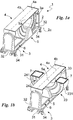
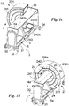
Figs. 1a - 1e show, in perspective, a radiological imaging device according to the invention in a possible operating sequence; -
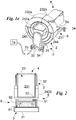
Fig. 2 illustrates, in a front view, a cross-section of the radiological imaging device in a step of the operating sequence inFigs. 1a-1e ; -
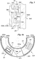
Fig. 3 shows a portion in cross-section of the radiological imaging device; -
Figs. 4a-4b show, in cross-section, an assembly of the radiological imaging device according to the invention in two different configurations; and -
Fig. 5 shows a portion of the radiological imaging device. - Herein, the measures, values, shapes and geometric references (such as perpendicularity and parallelism), when used with words like "about" or other similar terms such as "approximately" or "substantially", are to be understood as except for measurement errors or inaccuracies due to production and/or manufacturing errors and, above all, except for a slight divergence from the value, measure, shape or geometric reference which it is associated with. For example, said terms, if associated with a value, preferably indicate a divergence of not more than 10% of said value.
- In addition, where used terms such as "first", "second", "upper", "lower", "main" and "secondary" do not necessarily refer to an order, a priority relationship or relative position, but may simply be used to more clearly distinguish different components from each other.
- Except where specified otherwise, as evidenced by the discussions below, consider that terms such as "processing", "computer", "computing", "evaluation", or the like refer to the action and/or a processes of a computer or calculation system which handles and/or processes data represented as physical, such as electronic magnitudes of logs of a computer system and/or memories of other data similarly represented such as physical quantities inside computer systems, logs or other information storage, transmission or display devices.
- With reference to the drawings mentioned, reference numeral 1 globally denotes a radiological imaging device according to the invention.
- It is suitable for use in the medical (human/veterinary) field for performing radiological imaging of at least one portion of the internal anatomy of a patient. In particular, the radiological imaging device 1 is suitable for use in the medical field (human/veterinary) for performing X-rays, CAT scans, fluoroscopy and other radiological imaging examinations.
- The device 1 comprises a
gantry 2 suitable to perform the X-ray imaging; and acontrol unit 1a suitable to manage the operation of the device 1 and, to be precise, at least thegantry 2. - The
gantry 2 defines ananalysis area 2a suitable to contain at least a portion of the patient to be analysed and, appropriately, acircular extension trajectory 2b extending, and thus having its centre, on acentral axis 2c. - It is to be noted that in the present document the terms "axial", "axially" and similar identify a direction substantially parallel to the
central axis 2c, while the terms "radial", "radially" and similar identify a direction substantially perpendicular to thecentral axis 2c. - The
circular extension trajectory 2b lies on a plane substantially perpendicular to thecentral axis 2c. - The
gantry 2 comprises asource 21 suitable to emit a radiation, preferably X-rays, defining acentral propagation axis 21a preferably approximately perpendicular to thecentral axis 2c; adetector 22 suitable to receive the radiation after it has crossed theanalysis area 2a and, therefore, the portion of the patient in analysis; and acasing 23 defining a volume for housing at least thesource 21, thedetector 22 and extending substantially along thecircular extension trajectory 2b. - The
source 21 comprises an X-ray emitter defining thecentral axis 21a and, optionally, a tilt-system suitable to rotate, appropriately, with respect to thecasing 23, the X-ray emitter and, therefore, thepropagation axis 21a, preferably around a tilt-axis approximately parallel to thecentral axis 2c and, more preferably, passing through the focal spot of the emitter so as to maintain approximately stationary the focal spot. - The
detector 22 comprises at least one sensor defining a surface sensitive to X-rays and suitable to selectively perform, appropriately on the basis of a command given by the operator, tomographies, fluoroscopies and/or X-rays. It consequently defines at least one sensitive surface suitable to detect the radiation and, in particular, substantially perpendicular to the axis ofpropagation 21a. - The at least one sensor may comprise at least one between: a linear sensor and, preferably, two linear sensors defining sensitive surfaces substantially coplanar; a rectangular sensor, known as a flat panel, preferably suitable to vary the extension of the active sensitive surface; a direct photon count sensor; a dual energy sensor; a concavity sensor directed towards the
central axis 2c; a variable geometry sensor: flat or concave. - The
detector 22 may further comprise at least one lateral and/or vertical movement apparatus and, in detail, at least one waver suitable to translate along a waving axis and a lifting system suitable to move the sensor along a lifting axis approximately perpendicular to the waving axis. - The waver presents a slider connected to the sensor, a waving guide defining the waving axis and a motor, in detail electric, controlling the movement of the slider on the waving guide.
- The waving axis is substantially perpendicular to the
central propagation axis 21a and to thecentral axis 2c. - The lifting system comprises a linear actuator, preferably electric, suitable to move the sensor and, preferably, the waver along the lifting axis.
- The lifting axis is approximately parallel to the central axis of
propagation 21a and substantially perpendicular to thecentral axis 2c. - The
casing 23 constitutes the outer body of thegantry 2 and consequently, defines the overall dimensions and, in particular, the angular extension of thegantry 2 and thetrajectory 2b. - The
casing 23 and therefore thegantry 2 are of the telescopic type and, consequently, suitable to vary their angular extension along theextension trajectory 2b preferably defining at least a rest configuration and at least one working configuration for thegantry 2. - Advantageously, the
casing 23 and therefore thegantry 2 vary their angular extension and, therefore, the angular extension of the housing defined by thecasing 23, keeping thesource 21 anddetector 22 inside said housing volume. - In the rest configuration (
Figs. 1a-1b ,2 ,4a ) thecasing 23 and thegantry 2 are contracted and have a minimum angular extension. Consequently, thecasing 23, thegantry 2 and therefore thecircular extension trajectory 2b define an arc of circumference substantially centred on theaxis 2c and having an angular extension approximately less than 260°. In detail, in the rest configuration thetrajectory 2b has a minimum angular extension of angular amplitude approximately less than 210° and, in more detail, substantially equal to 190°. - In the at least one working configuration (
Figs. 1c-1e ,4b ), thecasing 23 and thegantry 2 have acircular extension trajectory 2b having a greater angular extension than said minimum angular extension so as to at least partially surround at least a major portion of theanalysis area 2a allowing thesource 21 and thedetector 22 to place themselves on opposite sides of theaxis 2c and thus thearea 2a. - In particular the
gantry 2 defines a working configuration of maximum extension (Figs. 1e ,4b ), in which thecasing 23 and therefore thegantry 2 are approximately closed and present thecircular extension trajectory 2b which presents an angular extension of 360° defining, accordingly, an O-shaped gantry 2 enclosing and, suitably, laterally delimiting theentire analysis area 2a. - It is to be noted how the
gantry 2 passes from one configuration to the other keeping thesource 21 anddetector 22 always inside the housing volume regardless of the angular extension of thecasing 23 and thus of thegantry 2 along thecircular extension trajectory 2b, as more fully described below. - Appropriately, in some cases, if the sensor is moved by the lifting system with a stroke of greater amplitude than a predefined threshold, the
detector 22 can come out and protrude at least partially from thecasing 23. - In fact, to allow the lifting system to move the sensor along the lifting axis, the
gantry 2 and, in particular, thecasing 23 may present a through window which faces theanalysis area 2a and allows thedetector 22 to protrude from thecasing 23 when translated along the lifting axis. - In order to have said configurations, the
casing 23 comprises at least two substantially hollow modules so as to define the housing volume. The modules have a preferred extension trajectory substantially coinciding with thecircular extension trajectory 2b, i.e. with the centre on thecentral axis 2c, and, advantageously, different cross-sections allowing for their mutual insertion/ overlapping. - In detail, the
casing 23 comprises at least one, preferably only one, bottomarched module 231 and at least one arched module mobile with respect to thebottom module 231 so as to vary the angular extension of thecasing 23 and of the gantry and, thus, the housing volume. - More in detail, the
casing 23 comprises a bottomarched module 231, a first mobilearched module 232a and a second mobilearched module 232b placed at the end of thebottom module 231 opposite thefirst module 232a and preferably substantially specular to saidfirst module 232a. - It is to be noted how the
mobile modules trajectory 2b, and independently of each other. - The
arched modules circular extension trajectory 2b. - In order to have, in the working configuration of maximum extension, an O-shaped
gantry 2, the sum of the angular amplitudes of themodules modules mobile modules bottom module 231 suitable to give greater structural stability to thegantry 2. - In particular, the bottom
arched module 231 has an angular extension approximately less than 240° and, more particularly, substantially less than 210° and, even more particularly, substantially comprised between 190° and 160°. Each mobilearched module bottom module 231 so that, when, the radiological imaging device is in the rest configuration, themobile modules bottom module 231 and spaced apart defining afree sector 231a of thebottom module 231. - Appropriately, the
mobile modules free sector 231a is appropriately placed in the middle of thebottom body 231, i.e. at the bisector of the angle of extension of thebottom body 231. - In particular, each mobile
arched module - The mobile
arched modules arched module 231 so as to at least partially overlap thebottom module 231 and, advantageously, vary the extension of the part of themobile module bottom module 231 during a change of configuration. Preferably, the mobilearched modules bottom module 231 so as to be housed inside it and, advantageously, vary the extension of the part of themobile module arched bottom module 231 during a change of configuration. Preferably, in the rest configuration each archedmobile module bottom module 231 so that the angular extension of thegantry 2 is substantially equal to that of thebottom module 231. More preferably, in the rest configuration the mobilearched modules arched bottom module 231. - In the at least one working configuration, at least one of the mobile
arched modules arched module bottom module 231 so that the angular extent of thegantry 2 is greater than that of thebottom module 231. In detail, in the at least one working configuration, the angular extension of thegantry 2 is approximately equal to the angular extension of thebottom module 231 plus the angular extension of each portion of mobilearched module arched bottom module 231. - It is to be noted how the
bottom module 231, having to contain inside it themobile modules mobile modules mobile modules bottom module 231. - The
modules - In order to move the at least one mobile
arched module 232a and/or 232b with respect to the bottomarched module 231 and, thus control the passage between the working and rest configurations, thegantry 2 comprises amovement apparatus 24 of at least the mobilearched modules 232a and/or 232b with respect to the bottomarched module 231. - Advantageously, the
movement apparatus 24 is suitable to move both themobile modules bottom module 231 allowing, in addition to said change of configuration, thesource 21 anddetector 22 to rotate around theanalysis area 2a and, thus thecentral axis 2c defining a rotation of maximum amplitude at least equal to 360°. - The
apparatus 24 includes at least abottom guide 241 integral with thearched bottom module 231 and defining abottom movement trajectory 241a, at least onemobile guide 242 integral with the at least one arched mobile module and defining amobile movement trajectory 242a, and at least onethrust assembly 243 suitable to engage at least one of theguides 241 and/or 242 controlling the rotation of the at least one correspondingarched module central axis 2c. - In particular, the
mobile guide 242 is integral with both mobilearched modules first sector 242b integral with the first archedmobile module 232a and defining a first portion of themobile trajectory 242a; and asecond sector 242c integral with the second archedmobile module 232b and defining a second portion of themobile trajectory 242a. - The
guides casing 23. Accordingly, themover 242 is also external to the housing volume and to thecasing 23. - The
bottom guide 241 is made on at least one of the outer faces of thearched bottom module 231 preferably not facing theanalysis area 2a. More preferably, it is made on at least one and, in particular, on only one of the outer faces of thearched bottom module 231 approximately perpendicular to thecentral axis 2c. - The
mobile guide 242 and, thus, thesectors arched modules analysis area 2a. Preferably, it is made on at least one and, in particular on only one of the external faces of the mobilearched modules central axis 2c. - Appropriately, the
guides arched modules mobile modules bottom module 231. - The
guides movement trajectories axis 2c. - Preferably, the
mobile guide 242 and themobile trajectory 242a are distinct from thebottom guide 241 and from thebottom trajectory 241a so that, when the archedmobile module arched bottom module 231, i.e. there is a change of configuration of thegantry 2, the surfaces of theguides trajectories mobile guide 242 overlapped on thebottom guide 241. - It is to be noted how the
mobile guide 242 and, consequently, themobile trajectory 242a are separate from thebottom guide 241 and from thebottom trajectory 241a by having a different radius, calculated with respect to theaxis 2c or a different position along thecentral axis 2c, i.e. the lying planes of thetrajectories central axis 2c in two separate points. Preferably, themobile guide 242 and themobile trajectory 242a have a different radius and, in particular smaller than that of thebottom guide 241 and of thebottom trajectory 241a. - The angular amplitude of the
mobile guide 242 and, to be precise, theindividual sectors bottom guide 241, may be approximately more than 360° so that thegantry 2 always has, even in the working configuration at maximum extension, at least one overlapping area between theguides mobile guide 242 and thebottom guide 241 are present so that thethrust unit 243 is simultaneously engageable to both of theguides - In detail, the sum of the angular extensions of the
guides movement trajectories - To be precise, the
bottom guide 241 has an angular extension approximately equal to that of thebottom module 231. In detail, it has approximately an angular extension approximately smaller than 240°, preferably 210° and, more preferably, substantially between 190° and 180°. - The
mobile guide 242 has an angular extension approximately less than 240°, preferably 210° and, more preferably, approximately comprised between 190° and 180°. In detail, eachsector mobile module sector - The
thrust assembly 243 is external to thecasing 23 and is suitable to engage, individually and/or simultaneously, theguides arched modules - As shown in
Fig. 3 , it comprises at least afirst engagement element 2431 to thebottom guide 241 suitable to control the rotation of at least thearched bottom module 231; at least onesecond engagement element 2432 to themobile guide 242 suitable to control the rotation of at least one archedmobile module support 2433 for saidelements - In order to allow the
thrust assembly 243 to always be in contact with at least one of theguides first engagement element 2431 and/or the at least onesecond engagement element 2432 may respectively define afirst engagement area 2431a and asecond engagement area 2432a at least partially overlapping one another radially, i.e. along a first approximately radial direction, suitably acircular extension trajectory 2b, and having a suitable angular amplitude. Said radial overlap identifies the fact that theengagement areas engagement area element respective guide several elements 2431 and/or 2432, it is identifiable in the arch enclosed between the areas of severalexternal elements respective guide thrust assembly 243 comprises severalfirst engagement elements 2431 mutually angularly spaced along thecircular extension trajectory 2b so as to engage to thebottom guide 241 in different points and, thus, have a broaderfirst engagement area 2431a. In detail, thefirst engagement elements 2431 have a mutual angular distance and, therefore, an amplitude of thefirst engagement area 2431a substantially at least equal to 10° and, to be precise, substantially comprised between 10° and 30°. - The
first engagement element 2431 is identifiable in a toothed wheel, motorised, suitably electrically, and thebottom guide 241 is identifiable in a rack. - Alternatively, the
bottom guide 241 is substantially smooth and, suitably, thefirst element 2431 is identifiable in a friction wheel (i.e. suitably coated or made of rubber or other high friction material) motorised, preferably, electrically, i.e. a wheel suitable to engage to thebottom guide 241 and to exploit the friction force between the wheel and thebottom guide 241 to move thebottom module 231. Appropriately, thethrust assembly 243 comprises severalsecond engagement elements 2432 mutually angularly spaced along thecircular extension trajectory 2b so as to engage to themobile guide 242 in different points and, thus, have a broadersecond engagement area 2432a. In detail, thesecond engagement elements 2432 have a mutual angular distance and, therefore, an amplitude of thesecond engagement area 2432a at least equal to 10° and, to be precise, substantially comprised between 10° and 30°. - Each
second engagement element 2432 is identifiable in at least one toothed wheel, motorised, suitably electrically, and themobile guide 242 is identifiable in a rack. - Alternatively, the
mobile guide 242 is approximately smooth and, suitably, coated in rubber or other high friction material and thesecond element 2432 is a friction wheel, motorised, preferably electrically. - Lastly, to allow the second engagement element of the 2432 to engage to the
mobile guide 242 even when themobile module 232a and/or 232b is inside thebottom module 231 themovement apparatus 24 comprises at least one throughslot 244 made on thebottom module 231 and suitable to overlap themobile guide 242 so as to appropriately put it into view through said bottomarched module 231 allowing an engagement between the second thrust means 2432, external to thecasing 23, and themobile guide 242 constrained to themobile modules casing 23. - In particular, the
movement apparatus 24 comprises a single throughslot 244 having an angular extension substantially equal to that of the bottomarched module 231 and extending substantially along thesecond trajectory 242a. Alternatively, it comprises two through slots 244 (Fig. 4b ) of which one having an angular extension approximately equal to thefirst sector 242b and the other having an angular extension approximately equal to thesecond sector 242c. Additionally, themovement apparatus 24, to allow themodules thrust assembly 243 and guides 241 and 242; and an axial constraint suitable to prevent a relative axial motion between thethrust assembly 243 and theguides movement apparatus 24 comprises both said radial constraint and said axial constraint. - The radial constraint, shown in
Fig. 3 , comprises at least afirst abutment 251 suitable to engage to thebottom guide 241 on the opposite side to thefirst engagement element 2431; and at least asecond abutment 252 suitable to engage themobile guide 242 on the side opposite thesecond element 2432. - The
abutments - The axial constraint, shown in
Fig. 3 , comprises afirst prominence 261 protruding radially from thebottom guide 241 and distal from thebottom module 231 so as to enclose thefirst engagement element 2431 between saidfirst prominence 261 and thebottom module 231; and asecond prominence 262 protruding radially from themobile guide 242 and distal from themobile module bottom module 231 so as to enclose thefirst engagement element 2431 between saidsecond prominence 262 and thebottom module 231. In order to stably reciprocally lock thearched modules bottom module 231 and, thus, thegantry 2 in any configuration, thegantry 2 comprises at least one lock, placed appropriately in the housing volume, suitable to selectively lock or prevent the relative sliding between saidarched modules modules modules - In particular, the gantry comprises a first lock suitable to stably constrain the first
mobile module 232a to the bottomarched module 231 and a second lock suitable to stably constrain thesecond module 232b to thebottom module 231. - To be precise, the first lock defines a first locking position in which it prevents the relative movement between the first arched
mobile module 232a and the bottomarched module 231 and a first release position in which it allows the relative movement between the first mobilearched module 232a and the bottomarched module 231. - The second lock defines a second locking position in which it prevents the relative movement between the second
mobile module 232b and the bottomarched module 231 and a second release position in which it allows the relative movement between the second archedmobile module 232b and the bottomarched module 231. - Each lock is identifiable in a linear actuator integral with the
mobile module bottom module 231 and suitable to vary its own length, suitably along a substantially radial direction with respect to thecircular trajectory 2b so that, in the locked position, the contact surface presses against thebottom module 231 mutually stably constraining themodules bottom module 231 allowing a mutual sliding between said modules. - Lastly, the
gantry 2 and, in particular, thecasing 23 comprise means ofconstraint 233 between the arched modules suitable to allow the modules to approximately exclusively slide substantially along thecircular extension trajectory 2b. - Said means of
constraint 233 are consequently suitable to prevent relative radial and axial movements between thearched modules - They comprise at least one circular engagement flap extending substantially along at least a portion of the through
slot 244 modules so as to reciprocally engage themodules - In particular, the means of
constraint 233 comprise, for each mobilearched module arched module 231 at the throughslot 244. More specifically, the means ofconstraint 233 comprise, for each mobilearched module slot 244. - Preferably, a circular flap has a first portion protruding axially from the mobile
arched module slot 244 and a second portion protruding radially from the first portion and, in detail, distal from the mobilearched module arched module 231 between said second portion and a mobilearched module - The
gantry 2 is suitable to vary its angular extension maintaining, appropriately always, thesource 21 and thedetector 22 inside the housing volume regardless of the angular extension of thecasing 23. It may consequently comprise at least a support suitable to constrain thesource 21 and thedetector 22 to thecasing 23 and, specifically, inside the housing volume. - Specifically, the support is suitable to constrain the
source 21 and thedetector 22 to at least onearched module - To allow the device 1 to pass from the rest configuration to the working configuration placing the
source 21 opposite thedetector 22 with respect to thecentral axis 2c, thegantry 2 comprises afirst support 27 for thesource 21 and asecond support 28 for thedetector 22. - Specifically, the
first support 27 is suitable to stably constrain thesource 21 to one between the bottomarched module 231 and amobile module second support 28 is suitable to stably constrain thedetector 21 to one between amobile module second support 28 are suitable to stably constrain thesource 21 and thedetector 22 respectively to abottom module 231 and to amobile module - In order to allow the passage into the rest configuration, the
first support 27 is suitable to constrain thesource 21 to the bottom arched module cantilevered, i.e. not in contact with any inner surface of thebottom module 231 so that a mobile module is able to position itself between thesource 21 and thebottom module 231. - To such purpose, the
first support 27, as shown inFig. 4a and4b , comprises aprop 271 integral with thebottom module 231 and suitable to support thesource 21 cantilevered so as to allow a mobilearched module source 21 and the bottomarched module 231; and, appropriately, at least oneretractable foot 272 suitable to rest on amodule source 21 on the distal side and, in detail, opposite theprop 271 and, more specifically, to the anchor point of theprop 271 to the bottom arched module 231 (i.e. at the cantilever end of theprop 271 and/orsource 21 and thus, at greater distance from the bottomarched module 231 as shown inFig. 4b ). - The
prop 271 is constrained to thebottom module 231 at thefree sector 231a so as not to interfere with themobile modules - The
retractable foot 272 is suitable to rest on the bottomarched module 231 at least in the fully extended configuration and on a mobilearched portion - It comprises a stand 2721 hinged to the
source 21 and elastic means 2722, appropriately a compression spring, suitable to retract the stand 2721 with respect to thesource 21. - Optionally, the
second support 28 may comprise a carriage for thedetector 22 and a rail integral with the secondmobile module 232b and suitable to define, for the carriage, a circular trajectory preferably substantially coincident with thetrajectory 2b. - Alternatively, the
first support 27 is suitable to constrain thesource 21 to the first mobilearched module 232a and thesecond support 28 is suitable to constrain thedetector 22 to the second mobilearched module 232b. - In this case, in order to allow the positioning of the
source 21 and thedetector 22 on opposite sides of the central axis, thefirst support 27 may comprise a first slider integral with thesource 21 and a first rail integral with thefirst module 232a and suitable to define, for the first slider, a first circular sliding trajectory approximately coincidental with theextension trajectory 2b; and thesecond support 28 may comprise a second slider integral with thedetector 22 and a second rail integral with the secondmobile module 232b and suitable to define, for the second slider, a second circular sliding trajectory preferably substantially coincident with thetrajectory 2b. - Said rails define for the relative sliders a stroke of substantially at least 10° and, in particular, substantially between 30° and 50°.
- In particular, said rails are suitable to place at least one between the
source 21 anddetector 22 cantilevered with respect to the relevantmobile module source 21 and thedetector 22 to be on opposite sides with respect to thecentral axis 2c. - The
control unit 1a is connected to the other components of the device 1 by awire 1b and/or via a wireless connection. It is suitable to control and command at least thegantry 2 and its movements. Theunit 1a comprises a control card able to automatically monitor and control the radiological imaging device 1; and interface components (touch-screen, keyboard, etc.) suitable to enable the operator to control the imaging device 1. - In particular, the
control unit 1a is suitable to control the operation of thethrust assembly 243 so as to define if and whichmodule - Appropriately, the
control unit 1a is suitable to control the operation of at least one lock and, specifically, their passage between the locked position and release position. More particularly, thecontrol unit 1a, placing the locks in the locked position causes thethrust assembly 243 to rotate theentire gantry 2 and placing at least one of the locks in the release position, makes thethrust assembly 243 perform a relative movement between at least onemobile module bottom module 231 and thus a change of configuration of thegantry 2. - In addition to the
gantry 2 and to theunit 1a, the radiological imaging device 1 may comprise abearing structure 3 suitable to support and move thegantry 2 and defining afree chamber 3a for thegantry 2; and in some cases, abed 4 suitable to be at least partially inserted in the area ofanalysis 2a and defining alongitudinal axis 4a and asupport surface 4b for the patient. - The
support surface 4b is substantially parallel to thecentral axis 2c and is suitable to position itself approximately parallel to the support surface of the imaging device 1. - The bearing
structure 3 comprises a base 31 suitable to support thegantry 2; at least onecolumn 32 suitable to sustain it in a raised position with respect to thebase 31, thebed 4; and, in some cases, 33 actuators suitable to move thebed 4 with respect to thebase 31. - Optionally, the radiological imaging device is portable and therefore the
structure 3 may comprise movement means 34 of the device 1, preferably castor wheels, suitable to position themselves between the ground andbase 31 enabling the movement of the device 1. - The
base 31 and at least onecolumn 32 define thechamber 3a. In detail, thechamber 3a is defined underneath, i.e. in the vicinity of the floor, by thebase 31; along a lateral side of thecolumn 32; if present, along a second lateral side opposite the first side of thesecond column 32; and optionally above thebed 4. Thefree chamber 3a has two open cross-sections for access to said chamber extending substantially parallel to thecentral axis 2c and, in particular, approximately perpendicular to thesupport surface 4b. - The
actuators 33 are placed between thebed 4 and eachcolumn 32 so as to change the extension of thechamber 3a by means of an approximately transverse translation and in particular perpendicular to thesupport surface 4b or, alternatively, independent of each other so to tilt thesurface 4b with respect to the gantry axis. - Alternatively, the
actuators 33 modify theinner chamber 3a by means of a rotation of thebed 2 around an axis substantially parallel to thecentral axis 2c. - Positioned between the base 31 and the
gantry 2, the radiological imaging device 1 has rotation means 5 defining an axis ofrotation 5a of thegantry 2; and translation means 6 defining atranslation axis 6a of thegantry 2. - The translation means 6 are placed between the base 31 and the
gantry 2 and comprise alinear guide 61, preferably motorised, suitable to control the translation along thetranslation axis 6a; atranslation element 62 joined to thegantry 2, in particular to thethrust assembly 243 and, more specifically, to thesupport 2433 and suitable to slide along thelinear guide 61 thereby translating saidgantry 2. - The
translation axis 6a is substantially parallel to thecentral axis 2c. - The means of
rotation 5 are positioned between the translation means 6 and thegantry 2 with respect to arotation axis 5a substantially transverse to theaxis 2c and, appropriately, to thesupport surface 4b so as to vary the mutual inclination between theaxes - The means of
rotation 5 comprise a fixedplate 51 suitable to be joined to thetranslation element 62; a mobile plate constrained to thecasing 23 and, to be precise, identifiable in thesupport 2433; pins, bearings or other similar elements defining therotation axis 5a; and a control lever 52suitable to be gripped by the operator and, thus, allow the operator to manually control the rotation around therotation axis 5a, of the mobile plate and thus of thegantry 2 with respect to the fixedplate 51. - The
control lever 52 is suitable to be associated with the holes on theplates 51 and thus define, for thegantry 2, a first rotational locked position wherein thecentral axis 2c is substantially parallel to thelongitudinal axis 4a, thetrajectory 2b lies on a plane substantially perpendicular to thelongitudinal axis 4a; and a second rotational locked position wherein thecentral axis 2c is approximately perpendicular to thelongitudinal axis 4a and theextension trajectory 2b lies in a plane approximately parallel to thelongitudinal axis 4a. In addition, thelever 52 defines a third rotational locked position wherein thecentral axis 2a is substantially parallel to thelongitudinal axis 4a, theextension trajectory 2b lies on a plane approximately perpendicular to thelongitudinal axis 4a, but thegantry 2 is rotated by 180° with respect to the first position. - As an alternative to the
lever 52, the rotation means 5 provide a motor suitable to control the aforesaid rotation of thegantry 2 and to define the first and second rotational locked positions and, if necessary, the third position. - Lastly, the imaging device 1 comprises one or more cover blocks 7, preferably two, suitable to seal the ends of the
casing 23 and in particular the mobilearched modules - The functioning of the radiological imaging device, described above in a structural sense, is as follows.
- Initially, the radiological imaging device 1 is in the rest configuration, i.e. with the
gantry 2 placed inside thefree chamber 3a and, therefore, thesupport surface 4b is approximately completely free and substantially accessible from any point. - In such rest configuration, the
gantry 2 has thecasing 23 with the mobilearched modules source 21 and thedetector 22 housed in the bottomarched module 231. - The operator places the patient on the
bed 4 and orders the passage into a desired working configuration (Fig. 1d ). - In particular, the
control unit 1a by means of the rotation means 5 rotates the gantry by about 90° thus placing theaxes - Now, the
casing 23 and thegantry 2 vary their extension along thecircular extension trajectory 2b until the desired angular extension is achieved. - It should be noted that during this configuration change, the mobile
arched modules circular extension trajectory 2b with opposite rotation directions from each other, placing themselves, in the working configuration of full extension, substantially in contact with each other. - The movements of the
first module 232a and of thesecond module 232b are respectively defined by at least one thrust assembly which initially rotates thebottom module 231 in order to engage thesecond engagement element 2432 to themobile guide 242 of the mobilearched modules - In detail, initially the
gantry 2 has the locks stably constraining the mobilearched modules bottom module 231; only thefirst engagement element 2431 engaged to thebottom guide 241 ; and thesecond element 2432 unengaged to themobile guide 242. - First of all, the
unit 1a and, in particular, thethrust assembly 243 drives thefirst engagement element 2431 so as to rotate theentire casing 23 up to engaging thesecond element 2432 in one of the sectors and, for example, to thefirst sector 242b. - At this point, the
unit 1a orders the first lock to pass into the release configuration, thus undoing the constraint between the first mobilearched module 232a and the bottomarched module 231 and thethrust assembly 243 drives thesecond element 2431 locking themodule 2432. Thesecond element 2432, acting on themobile guide 242 and, in particular, on thefirst sector 242b, makes the first mobilearched module 232a come out of the bottomarched module 231. - Moreover, such sliding of the first
mobile module 232a with respect to the bottomarched module 231 causes theretractable foot 272, initially resting on thefirst module 232a, to slide along saidfirst module 232a coming, finally to rest on the bottomarched module 231. - Once the portion of the first mobile
arched module 232a protruding from the bottom arched module has the desired angular extension, the first lock returns to the locked position and constrains the first mobilearched module 232a to the bottomarched module 231, thethrust assembly 243 drives thefirst engagement element 2431 so as to rotate, in the opposite direction to the previous, theentire casing 23 as far as engaging thesecond element 2432 to thesecond sector 242c. This in the condition in which the second module also needs to protrude from the bottomarched module 231. - At this point, the
unit 1a orders the second lock to release the constraint between the second mobilearched module 232b and the bottomarched module 231 and thethrust assembly 243 drives thesecond element 2431 locking thesecond element 2432. Thesecond element 2432, acting on thesecond sector 242c makes the second mobilearched module 232a come out of the bottomarched module 231. - Once the portion of the second mobile
arched module 232b protruding from the bottomarched module 231 has the desired angular extension, theunit 1a orders the second lock to constrain thesecond module 232b to the bottomarched module 231, i.e. to return to the locked position. - At this point the radiological imaging device has reached the desired working configuration and can begin scanning.
- It is to be noted how an appropriate alternative working configuration may be that in which only one of the two
modules arched module 231 so as to guarantee that thesource 21 is diametrically opposite thedetector 22 and to have a working configuration in which thegantry 2 has an angular extension of less than 360° and thus defines, between its ends of thecircular extension trajectory 2b, an access area during scanning. - It is to be noted how, if the
source 21 and the detector are not opposite with respect to thecentral axis 2c, at least one of thesupports detector 22 until it reaches said position. - At this point, the operator selects the type of radiological imaging and the portion of body to analyse.
- In response to such choice, the
control unit 1a defines the position whichsource 21 anddetector 22 must adopt and, as a result, thethrust assembly 243 drives at least one of the of theengagement elements 2431 and/or 2432 so as to rotate theentire casing 23 and move thesource 21 anddetector 22 into said position. - Once the
source 21 anddetector 22 have reached the desired position, either automatically or in response to a command given by the operator via thecontrol panel 1a, thesource 21 anddetector 22 perform the radiological imaging. - When the radiological imaging is completed, the operator can perform another scan or, alternatively, order the return of the device 1 to the rest configuration and, thus, perform surgery on the patient without ever moving the patient from the
bed 4 of said device. - The invention achieves important advantages.
- One of the most important advantages is that the imaging device 1, thanks to the possibility of varying the extension of the
gantry 2 and thus, placing it under thebed 4, makes it possible to perform a variety of operations/analyses on the patient without removed the same from thebed 4, even for long periods of time, without sacrificing the ability to perform scans from any angle. - Therefore, the innovative device allows the operator to leave the patient on the bed at all times without interruption performing on the same site both surgery and radiological scans of various types (X-rays, tomography and fluoroscopy) from all possible angles.
- In fact, in the rest configuration, the
gantry 2 being almost totally housed in thefree chamber 3a, the dimensions of the device 1 are defined exclusively by thebed 4 and by the bearingstructure 3 and, therefore, are substantially the same as those of an examination bed, i.e. a bed normally used to move the patient inside a hospital or to perform an operation on the patient. - As a result, the device 1 becomes a tool for continuous monitoring of the patient, i.e. able to perform, at any time, imaging of the patient which is utilisable in any part of a hospital (X-ray room, operating theatre, emergency room etc.) while at the same time allowing operations to be performed even in emergencies.
- The patient can, moreover, be transported from one place to another without ever leaving the device 1 according to the invention.
- In fact, in the rest configuration, the
gantry 2 being almost totally housed in thefree chamber 3a, the dimensions of the device 1 are defined exclusively by thebed 4 and by the bearingstructure 3. They are substantially the same as those of an examination bed, i.e. a bed normally used to move the patient inside a hospital or to perform an operation on the patient and such as to allow the device 1 to pass through doors, elevators or other openings normally found in a hospital. - This aspect is further increased by the fact that the imaging device 1, thanks to the
innovative gantry 2, does not need to be placed in shielded environments and/or provided with those special conditions characterising radiology rooms currently in use. - At the same time the innovative movement apparatus, defining a rotation path of the source and detector of angular amplitude 360° makes it possible to perform scans of 360° degrees or more without interruption.
- Another advantage is the fact that the radiological imaging device 1 has high structural simplicity thanks to the possibility of using a
single thrust assembly 243 to vary the configuration of the radiological imaging device 1 and to perform the scan. - A further advantage is the ease of assembly and maintenance of the
movement apparatus 24. - In fact, it is totally outside the
casing 23 and therefore easily accessible by an operator. - Another important advantage is determined by the fact that the
thrust apparatus 243, thanks to the presence of areas in which theguides 241 mutually overlap, is able to pass gradually from the engagement to thebottom guide 241 to themobile guide 242 and vice versa. - In addition, such smooth transition makes it possible to avoid creating vibrations or other similar noise determining unwanted oscillations of the
source 21 and/or of thedetector 22, detracting from the quality of the scan. - Another advantage of no less importance is given by the presence of
cover blocks 7 which sealing the ends of thegantry 2, prevent the entrance of blood, detritus or other materials that would damage the inner components of thegantry 2. - Another advantage is the fact that the
bed 4, thanks to theactuators 33 operable independently of each other, has two degrees of freedom with respect to thestructure 3 and thegantry 2. It is in fact, both translatable along an axis substantially perpendicular to thesupport surface 4b and tiltable/rotatable with respect to thecentral axis 2c. - Variations may be made to the invention without departing from the scope of the inventive concept described in the independent claims and in the relative technical equivalents. In said sphere all the details may be replaced with equivalent elements and the materials, shapes and dimensions may be as desired.
Claims (12)
- Radiological imaging device (1) comprising,- a gantry (2) defining an analysis area (2a) suitable to contain at least a portion of a patient to be analysed and a circular extension trajectory (2b) extending around a central axis (2c);- said gantry (2) comprisingsaid casing (23) comprising∘ a source (21) suitable to emit radiation;∘ a detector (22) suitable to receive said radiation after said radiation has passed through said analysis area (2a); and∘ a casing (23) defining a housing volume for at least said source (21) and said detector (22);- a bottom arched module (231),- at least one arched module mobile (232a, 232b) with respect to said bottom arched module (231) so as to vary the angular extension of said casing (23) and, thus, of said housing volume keeping said source (21) and said detector (22) in said housing volume;- said gantry (2) comprising, outside said housing volume, a movement apparatus (24) suitable to move said arched modules (231, 232a, 232b) and comprising- at least one bottom guide (241) integral with said bottom arched module (231) and defining a circular movement bottom trajectory (241a) substantially centred with respect to said central axis (2c);- at least one mobile guide (242) integral with said at least one mobile arched module (232a, 232b) and defining a circular movement mobile trajectory (242a) substantially centred with said central axis (2c);- at least one thrust assembly (243) suitable to engage said guides (241, 242), ordering the rotation of at least part of said arched modules (231, 232a, 232b) around said central axis (2c) so as to vary the angular extension of said casing (23) keeping said source (21) and said detector (22) in said housing volume; and- characterised in that said gantry (2) comprises a first support (27) constraining said source (21) to said bottom arched module (231) and a second support (28) constraining said detector (22) to one of said at least one arched mobile modules (232a, 232b).
- Radiological imaging device (1) according to the preceding claim, wherein said first support (27) constrains said source (21) to said bottom arched module (231) in a cantilever so that one of said at least one mobile arched modules (232a, 232b) can at least partially come between said source (22) and said bottom arched module (231).
- Radiological imaging device (1) according to the preceding claim, wherein said first support (27) comprises a prop (271) integral with said bottom arched module (231) and suitable to support said source (21) cantilevered; and at least a retractable foot (272) suitable to rest on one of said arched modules (231, 232a, 232b) and to support said source (21) on the opposite side to said prop (271).
- Radiological imaging device (1) according to one or more of the preceding claims wherein said at least one mobile arched module (232a 232b) has a substantially lesser cross-section to the cross-section of said bottom arched module (231) so that they can be housed inside said bottom arched module (231); and wherein said movement apparatus (24) comprises at least one through slot (244) made on said bottom arched module (231) and suitable to overlap said mobile guide (242) allowing an engagement between said at least one thrust assembly (243) and said mobile guide (242) when said at least one mobile arched module (232a 232b) is inside said bottom arched module (231).
- Radiological imaging device (1) according to one or more of the preceding claims, wherein said movement apparatus (24) comprises at least a first engagement element (2431) to said bottom guide (241) suitable to command the rotation of at least said bottom arched module (231); and at least a second engagement element (2432) to said mobile guide (242) suitable to command the rotation of said at least one mobile arched module (232a, 232b).
- Radiological imaging device (1) according to the preceding claim, wherein said at least one first engagement element (2431) and said at least one second engagement element (2432) define respectively a first engagement zone (2431a) and a second engagement zone (2432a) at least partly overlapping each other radially.
- Radiological imaging device (1) according to one or more of the preceding claims, wherein said thrust assembly (243) comprises a plurality of said at least one first engagement elements (2431); and wherein said first engagement elements (2431) are mutually angularly spaced along said circular extension trajectory (2b) so as to engage with said bottom guide (241) in distinct points.
- Radiological imaging device (1) according to the preceding claim, wherein said first engagement elements (2431) have a mutual angular distance substantially comprised between 10° and 30°.
- imaging device (1) according to one or more of the preceding claims, wherein said thrust assembly (243) comprises a plurality of said at least one second engagement elements (2432); and wherein said second engagement elements (2432) are mutually angularly spaced along said circular extension trajectory (2b) so as to engage with said mobile guide (242) in distinct points.
- Radiological imaging device (1) according to the preceding claim, wherein said second engagement elements (2432) have a mutual angular distance substantially comprised between 10° and 30°.
- Radiological imaging device (1) according to one or more of the preceding claims, wherein said gantry (2) comprises at least one lock suitable to block the relative sliding between said arched modules (231, 232a, 232b) defining a locked position in which it prevents the relative movement between said arched modules (231, 232a, 232b) and a release position in which it allows relative movement between said arched modules (231, 232a, 232b).
- Radiological imaging device (1) according to the preceding claim, comprising a control unit (1a) suitable to command the passage of said at least one lock into its locked position allowing said at least one thrust assembly (243) to rotate said gantry (2) around said central axis (2c); and wherein said control unit (1a) is suitable to control the passage of said at least one lock into the release position allowing said at least one thrust assembly (243) to reciprocally rotate said arched modules (231, 232a, 232b) defining a changed configuration of said gantry (2).
Applications Claiming Priority (2)
| Application Number | Priority Date | Filing Date | Title |
|---|---|---|---|
| ITUB2015A006291A ITUB20156291A1 (en) | 2015-12-04 | 2015-12-04 | RADIOLOGICAL IMAGE DEVICE |
| PCT/IB2016/056955 WO2017093841A1 (en) | 2015-12-04 | 2016-11-18 | Radiological imaging device |
Publications (2)
| Publication Number | Publication Date |
|---|---|
| EP3383274A1 EP3383274A1 (en) | 2018-10-10 |
| EP3383274B1 true EP3383274B1 (en) | 2019-09-18 |
Family
ID=55642572
Family Applications (1)
| Application Number | Title | Priority Date | Filing Date |
|---|---|---|---|
| EP16815646.1A Active EP3383274B1 (en) | 2015-12-04 | 2016-11-18 | Radiological imaging device |
Country Status (5)
| Country | Link |
|---|---|
| US (2) | US10758192B2 (en) |
| EP (1) | EP3383274B1 (en) |
| CN (1) | CN108601573A (en) |
| IT (1) | ITUB20156291A1 (en) |
| WO (1) | WO2017093841A1 (en) |
Families Citing this family (8)
| Publication number | Priority date | Publication date | Assignee | Title |
|---|---|---|---|---|
| US10653374B1 (en) * | 2017-01-30 | 2020-05-19 | Prescient Imaging, LLC | Portable positron emission tomography scanner having a rotatable detector ring which can be rotated 90 degrees for imaging a patient in a vertical or horizontal configuration |
| US11813098B2 (en) * | 2018-11-19 | 2023-11-14 | Siemens Medical Solutions Usa, Inc. | Translation drive system for an imaging system |
| EP3705048B1 (en) * | 2019-03-04 | 2021-04-21 | Boscherini, Duccio | A surgical table with an integrated imaging device |
| US11375962B2 (en) * | 2019-08-05 | 2022-07-05 | Linev Systems, Inc. | Fast foreign object scanner for scanning human bodies |
| US10987072B2 (en) * | 2019-09-18 | 2021-04-27 | Grigory Goldberg | Portable sterile C-arm cover |
| CN111543944B (en) * | 2020-04-21 | 2021-06-08 | 吉林大学 | An adjustment device for all-round inspection imaging in obstetrics and gynecology |
| US11534120B2 (en) | 2020-06-15 | 2022-12-27 | Medtronic Navigation, Inc. | Line scanner imaging device, system, and methods |
| CN111759336B (en) * | 2020-07-06 | 2022-12-30 | 南京安科医疗科技有限公司 | Automatic opening and closing device for O-shaped arm type CT and control method thereof |
Family Cites Families (12)
| Publication number | Priority date | Publication date | Assignee | Title |
|---|---|---|---|---|
| JPH02228946A (en) * | 1989-03-02 | 1990-09-11 | Toshiba Corp | X-ray ct scanner apparatus |
| JP3664462B2 (en) * | 1997-06-04 | 2005-06-29 | 株式会社東芝 | X-ray diagnostic equipment |
| US6619840B2 (en) * | 2001-10-15 | 2003-09-16 | Koninklijke Philips Electronics N.V. | Interventional volume scanner |
| EP1875866A3 (en) * | 2002-02-15 | 2008-07-30 | Breakaway Imaging, Llc | Gantry ring with detachable segment for multidimensional x-ray imaging |
| WO2006064402A2 (en) * | 2004-12-17 | 2006-06-22 | Koninklijke Philips Electronics, N.V. | Gantry system |
| US7840371B2 (en) * | 2006-05-22 | 2010-11-23 | Gaspardo & Associates, Inc. | Non-contact scanning system |
| DE102010020605A1 (en) * | 2010-05-14 | 2011-11-17 | Siemens Aktiengesellschaft | Medical examination device for CT imaging and nuclear medicine imaging |
| KR101095518B1 (en) * | 2010-06-29 | 2011-12-16 | 한국생산기술연구원 | Switchgear module, control method of switchgear module, and imaging device using the same |
| WO2014001835A1 (en) * | 2012-06-29 | 2014-01-03 | General Electric Company | Medical imaging system comprising a c-arm protection tunnel |
| JP6300795B2 (en) * | 2012-06-29 | 2018-03-28 | ゼネラル・エレクトリック・カンパニイ | Medical imaging system with C-arm and protective cover supported by two different vehicles |
| CN106879251B (en) * | 2014-07-16 | 2020-06-09 | 伊美姬艾利斯有限公司 | Radiographic equipment with a reduced footprint |
| WO2016020859A1 (en) * | 2014-08-07 | 2016-02-11 | Imaginalis S.R.L. | Radiological imaging device with improved manoeuvrability |
-
2015
- 2015-12-04 IT ITUB2015A006291A patent/ITUB20156291A1/en unknown
-
2016
- 2016-11-18 EP EP16815646.1A patent/EP3383274B1/en active Active
- 2016-11-18 US US15/781,117 patent/US10758192B2/en active Active
- 2016-11-18 WO PCT/IB2016/056955 patent/WO2017093841A1/en not_active Ceased
- 2016-11-18 CN CN201680081173.8A patent/CN108601573A/en active Pending
-
2020
- 2020-08-31 US US17/008,536 patent/US11723607B2/en active Active
Non-Patent Citations (1)
| Title |
|---|
| None * |
Also Published As
| Publication number | Publication date |
|---|---|
| US10758192B2 (en) | 2020-09-01 |
| CN108601573A (en) | 2018-09-28 |
| EP3383274A1 (en) | 2018-10-10 |
| ITUB20156291A1 (en) | 2017-06-04 |
| US20200397388A1 (en) | 2020-12-24 |
| WO2017093841A1 (en) | 2017-06-08 |
| US20180289339A1 (en) | 2018-10-11 |
| US11723607B2 (en) | 2023-08-15 |
Similar Documents
| Publication | Publication Date | Title |
|---|---|---|
| US11723607B2 (en) | Radiological imaging device | |
| US11202610B2 (en) | Radiological imaging system occupying a reduced space | |
| US10820869B2 (en) | Radiological imaging system with improved internal movement | |
| US10751012B2 (en) | Radiological imaging device with improved maneuverability | |
| EP3367901B1 (en) | Imaging device | |
| US20090082661A1 (en) | System and method to automatically assist mobile image acquisition | |
| US9301726B2 (en) | CT machine for multi-angle scanning of stationary patients | |
| US11083420B2 (en) | Robotic operating table and hybrid operating system | |
| US11707239B2 (en) | Radiological imaging device for lower limbs | |
| CN104968273A (en) | Extremity Imaging Setup for Cone Beam Computed Tomography | |
| CN106793988B (en) | Extremity imaging apparatus for cone beam computed tomography | |
| JP2019504680A (en) | Radiation imaging device | |
| JP4746270B2 (en) | Gantry ring for multidimensional X-ray imaging equipment with removable part | |
| EP3534795B1 (en) | Medical imaging device | |
| US9084582B2 (en) | Radiation imaging apparatus and method of controlling radiation imaging apparatus | |
| RU2573051C2 (en) | Patient table motion control apparatus | |
| CN102065767A (en) | Method and arrangement for mobile imaging system | |
| EP3442424B1 (en) | Mobile tomosynthesis system and method | |
| US20070140436A1 (en) | Dual telescoping support member digital radiography imaging system | |
| US20220104780A1 (en) | Radiological Filter | |
| JP2006284190A (en) | Scintillation camera device |
Legal Events
| Date | Code | Title | Description |
|---|---|---|---|
| STAA | Information on the status of an ep patent application or granted ep patent |
Free format text: STATUS: UNKNOWN |
|
| STAA | Information on the status of an ep patent application or granted ep patent |
Free format text: STATUS: THE INTERNATIONAL PUBLICATION HAS BEEN MADE |
|
| PUAI | Public reference made under article 153(3) epc to a published international application that has entered the european phase |
Free format text: ORIGINAL CODE: 0009012 |
|
| STAA | Information on the status of an ep patent application or granted ep patent |
Free format text: STATUS: REQUEST FOR EXAMINATION WAS MADE |
|
| 17P | Request for examination filed |
Effective date: 20180601 |
|
| AK | Designated contracting states |
Kind code of ref document: A1 Designated state(s): AL AT BE BG CH CY CZ DE DK EE ES FI FR GB GR HR HU IE IS IT LI LT LU LV MC MK MT NL NO PL PT RO RS SE SI SK SM TR |
|
| AX | Request for extension of the european patent |
Extension state: BA ME |
|
| DAV | Request for validation of the european patent (deleted) | ||
| DAX | Request for extension of the european patent (deleted) | ||
| REG | Reference to a national code |
Ref country code: DE Ref legal event code: R079 Ref document number: 602016021019 Country of ref document: DE Free format text: PREVIOUS MAIN CLASS: A61B0006030000 Ipc: A61B0006040000 |
|
| GRAP | Despatch of communication of intention to grant a patent |
Free format text: ORIGINAL CODE: EPIDOSNIGR1 |
|
| STAA | Information on the status of an ep patent application or granted ep patent |
Free format text: STATUS: GRANT OF PATENT IS INTENDED |
|
| RIC1 | Information provided on ipc code assigned before grant |
Ipc: A61B 6/04 20060101AFI20190322BHEP Ipc: A61B 6/00 20060101ALI20190322BHEP Ipc: A61B 6/03 20060101ALI20190322BHEP Ipc: A61B 6/10 20060101ALI20190322BHEP |
|
| INTG | Intention to grant announced |
Effective date: 20190417 |
|
| RIN1 | Information on inventor provided before grant (corrected) |
Inventor name: FORTUNA, DAMIANO Inventor name: DE SANTIS, GIOVANNI Inventor name: MANETTI, LEONARDO Inventor name: RAIMONDI, GIULIO |
|
| GRAS | Grant fee paid |
Free format text: ORIGINAL CODE: EPIDOSNIGR3 |
|
| GRAA | (expected) grant |
Free format text: ORIGINAL CODE: 0009210 |
|
| STAA | Information on the status of an ep patent application or granted ep patent |
Free format text: STATUS: THE PATENT HAS BEEN GRANTED |
|
| AK | Designated contracting states |
Kind code of ref document: B1 Designated state(s): AL AT BE BG CH CY CZ DE DK EE ES FI FR GB GR HR HU IE IS IT LI LT LU LV MC MK MT NL NO PL PT RO RS SE SI SK SM TR |
|
| REG | Reference to a national code |
Ref country code: GB Ref legal event code: FG4D |
|
| REG | Reference to a national code |
Ref country code: CH Ref legal event code: EP |
|
| REG | Reference to a national code |
Ref country code: DE Ref legal event code: R096 Ref document number: 602016021019 Country of ref document: DE |
|
| REG | Reference to a national code |
Ref country code: AT Ref legal event code: REF Ref document number: 1180358 Country of ref document: AT Kind code of ref document: T Effective date: 20191015 |
|
| REG | Reference to a national code |
Ref country code: IE Ref legal event code: FG4D |
|
| PGFP | Annual fee paid to national office [announced via postgrant information from national office to epo] |
Ref country code: LU Payment date: 20191125 Year of fee payment: 4 |
|
| REG | Reference to a national code |
Ref country code: NL Ref legal event code: MP Effective date: 20190918 |
|
| PG25 | Lapsed in a contracting state [announced via postgrant information from national office to epo] |
Ref country code: BG Free format text: LAPSE BECAUSE OF FAILURE TO SUBMIT A TRANSLATION OF THE DESCRIPTION OR TO PAY THE FEE WITHIN THE PRESCRIBED TIME-LIMIT Effective date: 20191218 Ref country code: NO Free format text: LAPSE BECAUSE OF FAILURE TO SUBMIT A TRANSLATION OF THE DESCRIPTION OR TO PAY THE FEE WITHIN THE PRESCRIBED TIME-LIMIT Effective date: 20191218 Ref country code: FI Free format text: LAPSE BECAUSE OF FAILURE TO SUBMIT A TRANSLATION OF THE DESCRIPTION OR TO PAY THE FEE WITHIN THE PRESCRIBED TIME-LIMIT Effective date: 20190918 Ref country code: LT Free format text: LAPSE BECAUSE OF FAILURE TO SUBMIT A TRANSLATION OF THE DESCRIPTION OR TO PAY THE FEE WITHIN THE PRESCRIBED TIME-LIMIT Effective date: 20190918 Ref country code: SE Free format text: LAPSE BECAUSE OF FAILURE TO SUBMIT A TRANSLATION OF THE DESCRIPTION OR TO PAY THE FEE WITHIN THE PRESCRIBED TIME-LIMIT Effective date: 20190918 Ref country code: HR Free format text: LAPSE BECAUSE OF FAILURE TO SUBMIT A TRANSLATION OF THE DESCRIPTION OR TO PAY THE FEE WITHIN THE PRESCRIBED TIME-LIMIT Effective date: 20190918 |
|
| PGFP | Annual fee paid to national office [announced via postgrant information from national office to epo] |
Ref country code: MC Payment date: 20191129 Year of fee payment: 4 |
|
| REG | Reference to a national code |
Ref country code: LT Ref legal event code: MG4D |
|
| PG25 | Lapsed in a contracting state [announced via postgrant information from national office to epo] |
Ref country code: AL Free format text: LAPSE BECAUSE OF FAILURE TO SUBMIT A TRANSLATION OF THE DESCRIPTION OR TO PAY THE FEE WITHIN THE PRESCRIBED TIME-LIMIT Effective date: 20190918 Ref country code: GR Free format text: LAPSE BECAUSE OF FAILURE TO SUBMIT A TRANSLATION OF THE DESCRIPTION OR TO PAY THE FEE WITHIN THE PRESCRIBED TIME-LIMIT Effective date: 20191219 Ref country code: RS Free format text: LAPSE BECAUSE OF FAILURE TO SUBMIT A TRANSLATION OF THE DESCRIPTION OR TO PAY THE FEE WITHIN THE PRESCRIBED TIME-LIMIT Effective date: 20190918 Ref country code: LV Free format text: LAPSE BECAUSE OF FAILURE TO SUBMIT A TRANSLATION OF THE DESCRIPTION OR TO PAY THE FEE WITHIN THE PRESCRIBED TIME-LIMIT Effective date: 20190918 |
|
| PGFP | Annual fee paid to national office [announced via postgrant information from national office to epo] |
Ref country code: MT Payment date: 20191128 Year of fee payment: 4 |
|
| REG | Reference to a national code |
Ref country code: AT Ref legal event code: MK05 Ref document number: 1180358 Country of ref document: AT Kind code of ref document: T Effective date: 20190918 |
|
| PG25 | Lapsed in a contracting state [announced via postgrant information from national office to epo] |
Ref country code: PT Free format text: LAPSE BECAUSE OF FAILURE TO SUBMIT A TRANSLATION OF THE DESCRIPTION OR TO PAY THE FEE WITHIN THE PRESCRIBED TIME-LIMIT Effective date: 20200120 Ref country code: NL Free format text: LAPSE BECAUSE OF FAILURE TO SUBMIT A TRANSLATION OF THE DESCRIPTION OR TO PAY THE FEE WITHIN THE PRESCRIBED TIME-LIMIT Effective date: 20190918 Ref country code: PL Free format text: LAPSE BECAUSE OF FAILURE TO SUBMIT A TRANSLATION OF THE DESCRIPTION OR TO PAY THE FEE WITHIN THE PRESCRIBED TIME-LIMIT Effective date: 20190918 Ref country code: EE Free format text: LAPSE BECAUSE OF FAILURE TO SUBMIT A TRANSLATION OF THE DESCRIPTION OR TO PAY THE FEE WITHIN THE PRESCRIBED TIME-LIMIT Effective date: 20190918 Ref country code: AT Free format text: LAPSE BECAUSE OF FAILURE TO SUBMIT A TRANSLATION OF THE DESCRIPTION OR TO PAY THE FEE WITHIN THE PRESCRIBED TIME-LIMIT Effective date: 20190918 Ref country code: ES Free format text: LAPSE BECAUSE OF FAILURE TO SUBMIT A TRANSLATION OF THE DESCRIPTION OR TO PAY THE FEE WITHIN THE PRESCRIBED TIME-LIMIT Effective date: 20190918 Ref country code: RO Free format text: LAPSE BECAUSE OF FAILURE TO SUBMIT A TRANSLATION OF THE DESCRIPTION OR TO PAY THE FEE WITHIN THE PRESCRIBED TIME-LIMIT Effective date: 20190918 |
|
| PG25 | Lapsed in a contracting state [announced via postgrant information from national office to epo] |
Ref country code: CZ Free format text: LAPSE BECAUSE OF FAILURE TO SUBMIT A TRANSLATION OF THE DESCRIPTION OR TO PAY THE FEE WITHIN THE PRESCRIBED TIME-LIMIT Effective date: 20190918 Ref country code: SM Free format text: LAPSE BECAUSE OF FAILURE TO SUBMIT A TRANSLATION OF THE DESCRIPTION OR TO PAY THE FEE WITHIN THE PRESCRIBED TIME-LIMIT Effective date: 20190918 Ref country code: SK Free format text: LAPSE BECAUSE OF FAILURE TO SUBMIT A TRANSLATION OF THE DESCRIPTION OR TO PAY THE FEE WITHIN THE PRESCRIBED TIME-LIMIT Effective date: 20190918 Ref country code: IS Free format text: LAPSE BECAUSE OF FAILURE TO SUBMIT A TRANSLATION OF THE DESCRIPTION OR TO PAY THE FEE WITHIN THE PRESCRIBED TIME-LIMIT Effective date: 20200224 |
|
| REG | Reference to a national code |
Ref country code: DE Ref legal event code: R097 Ref document number: 602016021019 Country of ref document: DE |
|
| PLBE | No opposition filed within time limit |
Free format text: ORIGINAL CODE: 0009261 |
|
| STAA | Information on the status of an ep patent application or granted ep patent |
Free format text: STATUS: NO OPPOSITION FILED WITHIN TIME LIMIT |
|
| PG2D | Information on lapse in contracting state deleted |
Ref country code: IS |
|
| PG25 | Lapsed in a contracting state [announced via postgrant information from national office to epo] |
Ref country code: DK Free format text: LAPSE BECAUSE OF FAILURE TO SUBMIT A TRANSLATION OF THE DESCRIPTION OR TO PAY THE FEE WITHIN THE PRESCRIBED TIME-LIMIT Effective date: 20190918 Ref country code: IS Free format text: LAPSE BECAUSE OF FAILURE TO SUBMIT A TRANSLATION OF THE DESCRIPTION OR TO PAY THE FEE WITHIN THE PRESCRIBED TIME-LIMIT Effective date: 20200119 |
|
| 26N | No opposition filed |
Effective date: 20200619 |
|
| PG25 | Lapsed in a contracting state [announced via postgrant information from national office to epo] |
Ref country code: SI Free format text: LAPSE BECAUSE OF FAILURE TO SUBMIT A TRANSLATION OF THE DESCRIPTION OR TO PAY THE FEE WITHIN THE PRESCRIBED TIME-LIMIT Effective date: 20190918 |
|
| PG25 | Lapsed in a contracting state [announced via postgrant information from national office to epo] |
Ref country code: CY Free format text: LAPSE BECAUSE OF FAILURE TO SUBMIT A TRANSLATION OF THE DESCRIPTION OR TO PAY THE FEE WITHIN THE PRESCRIBED TIME-LIMIT Effective date: 20190918 |
|
| PG25 | Lapsed in a contracting state [announced via postgrant information from national office to epo] |
Ref country code: MC Free format text: LAPSE BECAUSE OF NON-PAYMENT OF DUE FEES Effective date: 20201130 |
|
| PG25 | Lapsed in a contracting state [announced via postgrant information from national office to epo] |
Ref country code: LU Free format text: LAPSE BECAUSE OF NON-PAYMENT OF DUE FEES Effective date: 20201118 Ref country code: HU Free format text: LAPSE BECAUSE OF FAILURE TO SUBMIT A TRANSLATION OF THE DESCRIPTION OR TO PAY THE FEE WITHIN THE PRESCRIBED TIME-LIMIT; INVALID AB INITIO Effective date: 20161118 |
|
| PG25 | Lapsed in a contracting state [announced via postgrant information from national office to epo] |
Ref country code: TR Free format text: LAPSE BECAUSE OF FAILURE TO SUBMIT A TRANSLATION OF THE DESCRIPTION OR TO PAY THE FEE WITHIN THE PRESCRIBED TIME-LIMIT Effective date: 20190918 |
|
| PG25 | Lapsed in a contracting state [announced via postgrant information from national office to epo] |
Ref country code: MT Free format text: LAPSE BECAUSE OF NON-PAYMENT OF DUE FEES Effective date: 20201118 Ref country code: MK Free format text: LAPSE BECAUSE OF FAILURE TO SUBMIT A TRANSLATION OF THE DESCRIPTION OR TO PAY THE FEE WITHIN THE PRESCRIBED TIME-LIMIT Effective date: 20190918 |
|
| P01 | Opt-out of the competence of the unified patent court (upc) registered |
Effective date: 20230605 |
|
| PGFP | Annual fee paid to national office [announced via postgrant information from national office to epo] |
Ref country code: DE Payment date: 20241119 Year of fee payment: 9 |
|
| PGFP | Annual fee paid to national office [announced via postgrant information from national office to epo] |
Ref country code: BE Payment date: 20241119 Year of fee payment: 9 |
|
| PGFP | Annual fee paid to national office [announced via postgrant information from national office to epo] |
Ref country code: GB Payment date: 20241121 Year of fee payment: 9 |
|
| PGFP | Annual fee paid to national office [announced via postgrant information from national office to epo] |
Ref country code: FR Payment date: 20241128 Year of fee payment: 9 |
|
| PGFP | Annual fee paid to national office [announced via postgrant information from national office to epo] |
Ref country code: IE Payment date: 20241120 Year of fee payment: 9 |
|
| PGFP | Annual fee paid to national office [announced via postgrant information from national office to epo] |
Ref country code: IT Payment date: 20241108 Year of fee payment: 9 |
|
| PGFP | Annual fee paid to national office [announced via postgrant information from national office to epo] |
Ref country code: CH Payment date: 20241201 Year of fee payment: 9 |