EP3382904B1 - Effiziente strahlsuchverfahren zur dreidimensionalen strahlformung mit nicht vorcodierten referenzsignalen - Google Patents
Effiziente strahlsuchverfahren zur dreidimensionalen strahlformung mit nicht vorcodierten referenzsignalen Download PDFInfo
- Publication number
- EP3382904B1 EP3382904B1 EP17164097.2A EP17164097A EP3382904B1 EP 3382904 B1 EP3382904 B1 EP 3382904B1 EP 17164097 A EP17164097 A EP 17164097A EP 3382904 B1 EP3382904 B1 EP 3382904B1
- Authority
- EP
- European Patent Office
- Prior art keywords
- subspaces
- level
- subspace
- channel quality
- representative
- Prior art date
- Legal status (The legal status is an assumption and is not a legal conclusion. Google has not performed a legal analysis and makes no representation as to the accuracy of the status listed.)
- Active
Links
- 238000000034 method Methods 0.000 title claims description 133
- 238000013442 quality metrics Methods 0.000 claims description 196
- 238000012545 processing Methods 0.000 claims description 30
- 238000004891 communication Methods 0.000 description 25
- 230000006854 communication Effects 0.000 description 25
- 238000005516 engineering process Methods 0.000 description 16
- 238000010295 mobile communication Methods 0.000 description 13
- 238000013459 approach Methods 0.000 description 12
- 230000005540 biological transmission Effects 0.000 description 11
- 239000013598 vector Substances 0.000 description 11
- 239000011159 matrix material Substances 0.000 description 10
- 230000006870 function Effects 0.000 description 9
- 238000005259 measurement Methods 0.000 description 8
- 230000008569 process Effects 0.000 description 8
- 239000000872 buffer Substances 0.000 description 7
- 230000003044 adaptive effect Effects 0.000 description 5
- 230000001413 cellular effect Effects 0.000 description 5
- 238000013461 design Methods 0.000 description 4
- 238000010586 diagram Methods 0.000 description 4
- 239000007787 solid Substances 0.000 description 4
- 238000010276 construction Methods 0.000 description 3
- 230000009467 reduction Effects 0.000 description 3
- MOWXJLUYGFNTAL-DEOSSOPVSA-N (s)-[2-chloro-4-fluoro-5-(7-morpholin-4-ylquinazolin-4-yl)phenyl]-(6-methoxypyridazin-3-yl)methanol Chemical compound N1=NC(OC)=CC=C1[C@@H](O)C1=CC(C=2C3=CC=C(C=C3N=CN=2)N2CCOCC2)=C(F)C=C1Cl MOWXJLUYGFNTAL-DEOSSOPVSA-N 0.000 description 2
- ABDDQTDRAHXHOC-QMMMGPOBSA-N 1-[(7s)-5,7-dihydro-4h-thieno[2,3-c]pyran-7-yl]-n-methylmethanamine Chemical compound CNC[C@@H]1OCCC2=C1SC=C2 ABDDQTDRAHXHOC-QMMMGPOBSA-N 0.000 description 2
- BYHQTRFJOGIQAO-GOSISDBHSA-N 3-(4-bromophenyl)-8-[(2R)-2-hydroxypropyl]-1-[(3-methoxyphenyl)methyl]-1,3,8-triazaspiro[4.5]decan-2-one Chemical compound C[C@H](CN1CCC2(CC1)CN(C(=O)N2CC3=CC(=CC=C3)OC)C4=CC=C(C=C4)Br)O BYHQTRFJOGIQAO-GOSISDBHSA-N 0.000 description 2
- KCBWAFJCKVKYHO-UHFFFAOYSA-N 6-(4-cyclopropyl-6-methoxypyrimidin-5-yl)-1-[[4-[1-propan-2-yl-4-(trifluoromethyl)imidazol-2-yl]phenyl]methyl]pyrazolo[3,4-d]pyrimidine Chemical compound C1(CC1)C1=NC=NC(=C1C1=NC=C2C(=N1)N(N=C2)CC1=CC=C(C=C1)C=1N(C=C(N=1)C(F)(F)F)C(C)C)OC KCBWAFJCKVKYHO-UHFFFAOYSA-N 0.000 description 2
- 241000700159 Rattus Species 0.000 description 2
- 230000003321 amplification Effects 0.000 description 2
- 230000003993 interaction Effects 0.000 description 2
- 230000007774 longterm Effects 0.000 description 2
- 238000003199 nucleic acid amplification method Methods 0.000 description 2
- 230000002093 peripheral effect Effects 0.000 description 2
- 230000010363 phase shift Effects 0.000 description 2
- 238000012552 review Methods 0.000 description 2
- VCGRFBXVSFAGGA-UHFFFAOYSA-N (1,1-dioxo-1,4-thiazinan-4-yl)-[6-[[3-(4-fluorophenyl)-5-methyl-1,2-oxazol-4-yl]methoxy]pyridin-3-yl]methanone Chemical compound CC=1ON=C(C=2C=CC(F)=CC=2)C=1COC(N=C1)=CC=C1C(=O)N1CCS(=O)(=O)CC1 VCGRFBXVSFAGGA-UHFFFAOYSA-N 0.000 description 1
- MAYZWDRUFKUGGP-VIFPVBQESA-N (3s)-1-[5-tert-butyl-3-[(1-methyltetrazol-5-yl)methyl]triazolo[4,5-d]pyrimidin-7-yl]pyrrolidin-3-ol Chemical compound CN1N=NN=C1CN1C2=NC(C(C)(C)C)=NC(N3C[C@@H](O)CC3)=C2N=N1 MAYZWDRUFKUGGP-VIFPVBQESA-N 0.000 description 1
- ZGYIXVSQHOKQRZ-COIATFDQSA-N (e)-n-[4-[3-chloro-4-(pyridin-2-ylmethoxy)anilino]-3-cyano-7-[(3s)-oxolan-3-yl]oxyquinolin-6-yl]-4-(dimethylamino)but-2-enamide Chemical compound N#CC1=CN=C2C=C(O[C@@H]3COCC3)C(NC(=O)/C=C/CN(C)C)=CC2=C1NC(C=C1Cl)=CC=C1OCC1=CC=CC=N1 ZGYIXVSQHOKQRZ-COIATFDQSA-N 0.000 description 1
- APWRZPQBPCAXFP-UHFFFAOYSA-N 1-(1-oxo-2H-isoquinolin-5-yl)-5-(trifluoromethyl)-N-[2-(trifluoromethyl)pyridin-4-yl]pyrazole-4-carboxamide Chemical compound O=C1NC=CC2=C(C=CC=C12)N1N=CC(=C1C(F)(F)F)C(=O)NC1=CC(=NC=C1)C(F)(F)F APWRZPQBPCAXFP-UHFFFAOYSA-N 0.000 description 1
- HCDMJFOHIXMBOV-UHFFFAOYSA-N 3-(2,6-difluoro-3,5-dimethoxyphenyl)-1-ethyl-8-(morpholin-4-ylmethyl)-4,7-dihydropyrrolo[4,5]pyrido[1,2-d]pyrimidin-2-one Chemical compound C=1C2=C3N(CC)C(=O)N(C=4C(=C(OC)C=C(OC)C=4F)F)CC3=CN=C2NC=1CN1CCOCC1 HCDMJFOHIXMBOV-UHFFFAOYSA-N 0.000 description 1
- WNEODWDFDXWOLU-QHCPKHFHSA-N 3-[3-(hydroxymethyl)-4-[1-methyl-5-[[5-[(2s)-2-methyl-4-(oxetan-3-yl)piperazin-1-yl]pyridin-2-yl]amino]-6-oxopyridin-3-yl]pyridin-2-yl]-7,7-dimethyl-1,2,6,8-tetrahydrocyclopenta[3,4]pyrrolo[3,5-b]pyrazin-4-one Chemical compound C([C@@H](N(CC1)C=2C=NC(NC=3C(N(C)C=C(C=3)C=3C(=C(N4C(C5=CC=6CC(C)(C)CC=6N5CC4)=O)N=CC=3)CO)=O)=CC=2)C)N1C1COC1 WNEODWDFDXWOLU-QHCPKHFHSA-N 0.000 description 1
- SRVXSISGYBMIHR-UHFFFAOYSA-N 3-[3-[3-(2-amino-2-oxoethyl)phenyl]-5-chlorophenyl]-3-(5-methyl-1,3-thiazol-2-yl)propanoic acid Chemical compound S1C(C)=CN=C1C(CC(O)=O)C1=CC(Cl)=CC(C=2C=C(CC(N)=O)C=CC=2)=C1 SRVXSISGYBMIHR-UHFFFAOYSA-N 0.000 description 1
- KVCQTKNUUQOELD-UHFFFAOYSA-N 4-amino-n-[1-(3-chloro-2-fluoroanilino)-6-methylisoquinolin-5-yl]thieno[3,2-d]pyrimidine-7-carboxamide Chemical compound N=1C=CC2=C(NC(=O)C=3C4=NC=NC(N)=C4SC=3)C(C)=CC=C2C=1NC1=CC=CC(Cl)=C1F KVCQTKNUUQOELD-UHFFFAOYSA-N 0.000 description 1
- IRPVABHDSJVBNZ-RTHVDDQRSA-N 5-[1-(cyclopropylmethyl)-5-[(1R,5S)-3-(oxetan-3-yl)-3-azabicyclo[3.1.0]hexan-6-yl]pyrazol-3-yl]-3-(trifluoromethyl)pyridin-2-amine Chemical compound C1=C(C(F)(F)F)C(N)=NC=C1C1=NN(CC2CC2)C(C2[C@@H]3CN(C[C@@H]32)C2COC2)=C1 IRPVABHDSJVBNZ-RTHVDDQRSA-N 0.000 description 1
- CYJRNFFLTBEQSQ-UHFFFAOYSA-N 8-(3-methyl-1-benzothiophen-5-yl)-N-(4-methylsulfonylpyridin-3-yl)quinoxalin-6-amine Chemical compound CS(=O)(=O)C1=C(C=NC=C1)NC=1C=C2N=CC=NC2=C(C=1)C=1C=CC2=C(C(=CS2)C)C=1 CYJRNFFLTBEQSQ-UHFFFAOYSA-N 0.000 description 1
- AYCPARAPKDAOEN-LJQANCHMSA-N N-[(1S)-2-(dimethylamino)-1-phenylethyl]-6,6-dimethyl-3-[(2-methyl-4-thieno[3,2-d]pyrimidinyl)amino]-1,4-dihydropyrrolo[3,4-c]pyrazole-5-carboxamide Chemical compound C1([C@H](NC(=O)N2C(C=3NN=C(NC=4C=5SC=CC=5N=C(C)N=4)C=3C2)(C)C)CN(C)C)=CC=CC=C1 AYCPARAPKDAOEN-LJQANCHMSA-N 0.000 description 1
- IDRGFNPZDVBSSE-UHFFFAOYSA-N OCCN1CCN(CC1)c1ccc(Nc2ncc3cccc(-c4cccc(NC(=O)C=C)c4)c3n2)c(F)c1F Chemical compound OCCN1CCN(CC1)c1ccc(Nc2ncc3cccc(-c4cccc(NC(=O)C=C)c4)c3n2)c(F)c1F IDRGFNPZDVBSSE-UHFFFAOYSA-N 0.000 description 1
- LXRZVMYMQHNYJB-UNXOBOICSA-N [(1R,2S,4R)-4-[[5-[4-[(1R)-7-chloro-1,2,3,4-tetrahydroisoquinolin-1-yl]-5-methylthiophene-2-carbonyl]pyrimidin-4-yl]amino]-2-hydroxycyclopentyl]methyl sulfamate Chemical compound CC1=C(C=C(S1)C(=O)C1=C(N[C@H]2C[C@H](O)[C@@H](COS(N)(=O)=O)C2)N=CN=C1)[C@@H]1NCCC2=C1C=C(Cl)C=C2 LXRZVMYMQHNYJB-UNXOBOICSA-N 0.000 description 1
- 230000001154 acute effect Effects 0.000 description 1
- 230000006978 adaptation Effects 0.000 description 1
- 230000007175 bidirectional communication Effects 0.000 description 1
- 238000012937 correction Methods 0.000 description 1
- 238000001514 detection method Methods 0.000 description 1
- 238000011156 evaluation Methods 0.000 description 1
- 238000005562 fading Methods 0.000 description 1
- 230000002349 favourable effect Effects 0.000 description 1
- 230000009349 indirect transmission Effects 0.000 description 1
- 230000002452 interceptive effect Effects 0.000 description 1
- 230000004807 localization Effects 0.000 description 1
- 238000013507 mapping Methods 0.000 description 1
- 230000000116 mitigating effect Effects 0.000 description 1
- 238000012986 modification Methods 0.000 description 1
- 230000004048 modification Effects 0.000 description 1
- 230000003287 optical effect Effects 0.000 description 1
- 238000010845 search algorithm Methods 0.000 description 1
- XIIOFHFUYBLOLW-UHFFFAOYSA-N selpercatinib Chemical compound OC(COC=1C=C(C=2N(C=1)N=CC=2C#N)C=1C=NC(=CC=1)N1CC2N(C(C1)C2)CC=1C=NC(=CC=1)OC)(C)C XIIOFHFUYBLOLW-UHFFFAOYSA-N 0.000 description 1
- 230000011664 signaling Effects 0.000 description 1
- XGVXKJKTISMIOW-ZDUSSCGKSA-N simurosertib Chemical compound N1N=CC(C=2SC=3C(=O)NC(=NC=3C=2)[C@H]2N3CCC(CC3)C2)=C1C XGVXKJKTISMIOW-ZDUSSCGKSA-N 0.000 description 1
- 238000001228 spectrum Methods 0.000 description 1
- DZXKSFDSPBRJPS-UHFFFAOYSA-N tin(2+);sulfide Chemical compound [S-2].[Sn+2] DZXKSFDSPBRJPS-UHFFFAOYSA-N 0.000 description 1
Images


Classifications
-
- H—ELECTRICITY
- H04—ELECTRIC COMMUNICATION TECHNIQUE
- H04B—TRANSMISSION
- H04B7/00—Radio transmission systems, i.e. using radiation field
- H04B7/02—Diversity systems; Multi-antenna system, i.e. transmission or reception using multiple antennas
- H04B7/04—Diversity systems; Multi-antenna system, i.e. transmission or reception using multiple antennas using two or more spaced independent antennas
- H04B7/06—Diversity systems; Multi-antenna system, i.e. transmission or reception using multiple antennas using two or more spaced independent antennas at the transmitting station
- H04B7/0613—Diversity systems; Multi-antenna system, i.e. transmission or reception using multiple antennas using two or more spaced independent antennas at the transmitting station using simultaneous transmission
- H04B7/0615—Diversity systems; Multi-antenna system, i.e. transmission or reception using multiple antennas using two or more spaced independent antennas at the transmitting station using simultaneous transmission of weighted versions of same signal
- H04B7/0617—Diversity systems; Multi-antenna system, i.e. transmission or reception using multiple antennas using two or more spaced independent antennas at the transmitting station using simultaneous transmission of weighted versions of same signal for beam forming
-
- H—ELECTRICITY
- H04—ELECTRIC COMMUNICATION TECHNIQUE
- H04B—TRANSMISSION
- H04B7/00—Radio transmission systems, i.e. using radiation field
- H04B7/02—Diversity systems; Multi-antenna system, i.e. transmission or reception using multiple antennas
- H04B7/04—Diversity systems; Multi-antenna system, i.e. transmission or reception using multiple antennas using two or more spaced independent antennas
- H04B7/06—Diversity systems; Multi-antenna system, i.e. transmission or reception using multiple antennas using two or more spaced independent antennas at the transmitting station
- H04B7/0613—Diversity systems; Multi-antenna system, i.e. transmission or reception using multiple antennas using two or more spaced independent antennas at the transmitting station using simultaneous transmission
- H04B7/0615—Diversity systems; Multi-antenna system, i.e. transmission or reception using multiple antennas using two or more spaced independent antennas at the transmitting station using simultaneous transmission of weighted versions of same signal
- H04B7/0619—Diversity systems; Multi-antenna system, i.e. transmission or reception using multiple antennas using two or more spaced independent antennas at the transmitting station using simultaneous transmission of weighted versions of same signal using feedback from receiving side
- H04B7/0621—Feedback content
- H04B7/063—Parameters other than those covered in groups H04B7/0623 - H04B7/0634, e.g. channel matrix rank or transmit mode selection
-
- H—ELECTRICITY
- H04—ELECTRIC COMMUNICATION TECHNIQUE
- H04B—TRANSMISSION
- H04B7/00—Radio transmission systems, i.e. using radiation field
- H04B7/02—Diversity systems; Multi-antenna system, i.e. transmission or reception using multiple antennas
- H04B7/04—Diversity systems; Multi-antenna system, i.e. transmission or reception using multiple antennas using two or more spaced independent antennas
- H04B7/06—Diversity systems; Multi-antenna system, i.e. transmission or reception using multiple antennas using two or more spaced independent antennas at the transmitting station
- H04B7/0613—Diversity systems; Multi-antenna system, i.e. transmission or reception using multiple antennas using two or more spaced independent antennas at the transmitting station using simultaneous transmission
- H04B7/0615—Diversity systems; Multi-antenna system, i.e. transmission or reception using multiple antennas using two or more spaced independent antennas at the transmitting station using simultaneous transmission of weighted versions of same signal
- H04B7/0619—Diversity systems; Multi-antenna system, i.e. transmission or reception using multiple antennas using two or more spaced independent antennas at the transmitting station using simultaneous transmission of weighted versions of same signal using feedback from receiving side
- H04B7/0621—Feedback content
- H04B7/0632—Channel quality parameters, e.g. channel quality indicator [CQI]
-
- H—ELECTRICITY
- H04—ELECTRIC COMMUNICATION TECHNIQUE
- H04B—TRANSMISSION
- H04B7/00—Radio transmission systems, i.e. using radiation field
- H04B7/02—Diversity systems; Multi-antenna system, i.e. transmission or reception using multiple antennas
- H04B7/04—Diversity systems; Multi-antenna system, i.e. transmission or reception using multiple antennas using two or more spaced independent antennas
- H04B7/06—Diversity systems; Multi-antenna system, i.e. transmission or reception using multiple antennas using two or more spaced independent antennas at the transmitting station
- H04B7/0613—Diversity systems; Multi-antenna system, i.e. transmission or reception using multiple antennas using two or more spaced independent antennas at the transmitting station using simultaneous transmission
- H04B7/0615—Diversity systems; Multi-antenna system, i.e. transmission or reception using multiple antennas using two or more spaced independent antennas at the transmitting station using simultaneous transmission of weighted versions of same signal
- H04B7/0619—Diversity systems; Multi-antenna system, i.e. transmission or reception using multiple antennas using two or more spaced independent antennas at the transmitting station using simultaneous transmission of weighted versions of same signal using feedback from receiving side
- H04B7/0621—Feedback content
- H04B7/0634—Antenna weights or vector/matrix coefficients
-
- H—ELECTRICITY
- H04—ELECTRIC COMMUNICATION TECHNIQUE
- H04B—TRANSMISSION
- H04B7/00—Radio transmission systems, i.e. using radiation field
- H04B7/02—Diversity systems; Multi-antenna system, i.e. transmission or reception using multiple antennas
- H04B7/04—Diversity systems; Multi-antenna system, i.e. transmission or reception using multiple antennas using two or more spaced independent antennas
- H04B7/06—Diversity systems; Multi-antenna system, i.e. transmission or reception using multiple antennas using two or more spaced independent antennas at the transmitting station
- H04B7/0686—Hybrid systems, i.e. switching and simultaneous transmission
- H04B7/0695—Hybrid systems, i.e. switching and simultaneous transmission using beam selection
-
- H—ELECTRICITY
- H04—ELECTRIC COMMUNICATION TECHNIQUE
- H04L—TRANSMISSION OF DIGITAL INFORMATION, e.g. TELEGRAPHIC COMMUNICATION
- H04L25/00—Baseband systems
- H04L25/02—Details ; arrangements for supplying electrical power along data transmission lines
- H04L25/0202—Channel estimation
- H04L25/0204—Channel estimation of multiple channels
-
- H—ELECTRICITY
- H04—ELECTRIC COMMUNICATION TECHNIQUE
- H04L—TRANSMISSION OF DIGITAL INFORMATION, e.g. TELEGRAPHIC COMMUNICATION
- H04L25/00—Baseband systems
- H04L25/02—Details ; arrangements for supplying electrical power along data transmission lines
- H04L25/0202—Channel estimation
- H04L25/0224—Channel estimation using sounding signals
- H04L25/0228—Channel estimation using sounding signals with direct estimation from sounding signals
Definitions
- Various aspects described herein relate generally to methods and devices for three-dimensional beamforming, and more particularly to three-dimensional beamforming with non-precoded reference signals.
- Three-dimensional beamforming systems with non-precoded reference signals include the Third Generation Partnership Project (3GPP) Long Term Evolution (LTE) Full Dimensional Multiple Input Multiple Output (FD-MIMO) Class A configurations, where a codebook size for a given rank can reach up to 2,048 beam directions in Release-13 and even larger in later Releases. Therefore, the computational burden on a receiver can be sufficiently large enough to make an exhaustive search in determining a preferred beam direction impractical.
- 3GPP Third Generation Partnership Project
- LTE Long Term Evolution
- FD-MIMO Full Dimensional Multiple Input Multiple Output
- Each UE sends its SRS signal precoded in the spatial dimension corresponding to the chosen subspace, thus indirectly informing the BSs about that subspace.
- Steps performed at the Base Station Estimating main interference directions: Each BS must estimate (or compute, if possible) the precoded sounding sent by its own UE and estimate the covariance matrix of the interference based in signal received for interfering UEs. We will discuss how this can be performed later.
- any phrases explicitly invoking the aforementioned words expressly refers more than one of the said objects.
- the terms "proper subset,” “reduced subset,” and “lesser subset” refer to a subset of a set that is not equal to the set, i.e. a subset of a set that contains less elements than the set.
- references to a "vector” may refer to a vector of any size or orientation, e.g. including a 1x1 vector (e.g. a scalar), a 1xM vector (e.g. a row vector), and an Mx1 vector (e.g. a column vector).
- a 1x1 vector e.g. a scalar
- a 1xM vector e.g. a row vector
- Mx1 vector e.g. a column vector
- references to a "matrix” may refer to matrix of any size or orientation, e.g. including a 1x1 matrix (e.g. a scalar), a 1xM matrix (e.g. a row vector), and an Mx1 matrix (e.g. a column vector).
- a 1x1 matrix e.g. a scalar
- a 1xM matrix e.g. a row vector
- Mx1 matrix e.g. a column vector
- a “circuit” as user herein is understood as any kind of logic-implementing entity, which may include special-purpose hardware or a processor executing software.
- a circuit may thus be an analog circuit, digital circuit, mixed-signal circuit, logic circuit, processor, microprocessor, Central Processing Unit (“CPU”), Graphics Processing Unit (“GPU”), Digital Signal Processor (“DSP”), Field Programmable Gate Array (“FPGA”), integrated circuit, Application Specific Integrated Circuit (“ASIC”), etc., or any combination thereof.
- circuit Any other kind of implementation of the respective functions which will be described below in further detail may also be understood as a "circuit.” It is understood that any two (or more) of the circuits detailed herein may be realized as a single circuit with substantially equivalent functionality, and conversely that any single circuit detailed herein may be realized as two (or more) separate circuits with substantially equivalent functionality. Additionally, references to a "circuit" may refer to two or more circuits that collectively form a single circuit.
- memory may be understood as a non-transitory computer-readable medium in which data or information can be stored for retrieval. References to "memory” included herein may thus be understood as referring to volatile or non-volatile memory, including random access memory (“RAM”), read-only memory (“ROM”), flash memory, solid-state storage, magnetic tape, hard disk drive, optical drive, etc., or any combination thereof. Furthermore, it is appreciated that registers, shift registers, processor registers, data buffers, etc., are also embraced herein by the term memory.
- a single component referred to as "memory” or “a memory” may be composed of more than one different type of memory, and thus may refer to a collective component comprising one or more types of memory. It is readily understood that any single memory component may be separated into multiple collectively equivalent memory components, and vice versa. Furthermore, while memory may be depicted as separate from one or more other components (such as in the drawings), it is understood that memory may be integrated within another component, such as on a common integrated chip.
- base station used in reference to an access point of a mobile communication network may be understood as a macro base station, micro base station, Node B, evolved NodeB (eNB), Home eNodeB, Remote Radio Head (RRH), relay point, etc.
- a "cell” in the context of telecommunications may be understood as a sector served by a base station. Accordingly, a cell may be a set of geographically co-located antennas that correspond to a particular sectorization of a base station. A base station may thus serve one or more cells (or sectors), where each cell is characterized by a distinct communication channel.
- the term "cell” may be utilized to refer to any of a macrocell, microcell, femtocell, picocell, etc.
- radio communication technologies may be classified as one of a Short Range radio communication technology, Metropolitan Area System radio communication technology, or Cellular Wide Area radio communication technology.
- Short Range radio communication technologies include Bluetooth, WLAN (e.g. according to any IEEE 802.11 standard), and other similar radio communication technologies.
- Metropolitan Area System radio communication technologies include Worldwide Interoperability for Microwave Access (WiMax) (e.g. according to an IEEE 802.16 radio communication standard, e.g. WiMax fixed or WiMax mobile) and other similar radio communication technologies.
- WiMax Worldwide Interoperability for Microwave Access
- Cellular Wide Area radio communication technologies include Global System for Mobile Communications (GSM), Code Division Multiple Access 2000 (CDMA2000), Universal Mobile Telecommunications System (UMTS), Long Term Evolution (LTE), General Packet Radio Service (GPRS), Evolution-Data Optimized (EV-DO), Enhanced Data Rates for GSM Evolution (EDGE), High Speed Packet Access (HSPA), etc., and other similar radio communication technologies.
- GSM Global System for Mobile Communications
- CDMA2000 Code Division Multiple Access 2000
- UMTS Universal Mobile Telecommunications System
- LTE Long Term Evolution
- GPRS General Packet Radio Service
- EV-DO Evolution-Data Optimized
- EDGE Enhanced Data Rates for GSM Evolution
- HSPA High Speed Packet Access
- Cellular Wide Area radio communication technologies may be generally referred to herein as "cellular" communication technologies. It is understood that exemplary scenarios detailed herein are demonstrative in nature, and accordingly may be similarly applied to various other mobile communication technologies, both existing and not yet formulated, particularly in cases where such mobile communication technologies share
- network as utilized herein, e.g. in reference to a communication network such as a mobile communication network, encompasses both an access section of a network (e.g. a radio access network (RAN) section) and a core section of a network (e.g. a core network section).
- RAN radio access network
- core network section e.g. a core network section.
- radio idle mode or “radio idle state” used herein in reference to a terminal device refers to a radio control state in which the terminal device is not allocated at least one dedicated communication channel of a mobile communication network.
- radio connected mode or “radio connected state” used in reference to a terminal device refers to a radio control state in which the terminal device is allocated at least one dedicated uplink communication channel of a mobile communication network.
- the term “transmit” encompasses both direct (point-to-point) and indirect transmission (via one or more intermediary points).
- the term “receive” encompasses both direct and indirect reception.
- the term “communicate” encompasses one or both of transmitting and receiving, i.e. unidirectional or bidirectional communication in one or both of the incoming and outgoing directions.
- CSI channel state information
- MCS modulation and coding scheme
- beam direction beam direction
- precoding matrix precoding matrix
- the estimation of CSI at a receiver may be based on a reception performance prediction metric.
- a reception performance prediction metric is based on reference signals (e.g., pilot signals) that are provided by the transmitter.
- the form of the reference signals may vary from one communication system to another.
- these reference signals may be precoded (i.e., beamformed) or non-precoded (i.e., not beamformed).
- Precoded references signals may be designed to sweep through a set of predefined beams.
- non-precoded reference signals bear no beam specific information.
- a device such as a receiver (i.e., beamformee), of a particular beamforming system may estimate the CSI and convey the estimated CSI to another device, like a transmitter (i.e., beamformer) based on reference signals received therefrom.
- the CSI that is estimated by, for example, a receiver may include at least one indicator identifying one or more preferred beam directions, which correspond to a highest channel quality metric value or values.
- the determination of a preferred beam direction from among the number of candidate beam directions contributes to the computation burden at the receiver in a beamforming system.
- This challenge is especially acute in three-dimensional (3D) beamforming systems because a beam is associated with two spatial dimensions (i.e., azimuth and elevation) as opposed to one spatial dimension (i.e., azimuth) in conventional beamforming systems.
- 3D three-dimensional
- MIMO massive Multiple Input Multiple Output
- the computational burden of searching through the entire beam search space falls solely on the receiver. This is because any given observation for CSI estimation bears no beam-specific information.
- the receiver may conduct a global search over the beam space based on a codebook agreed between the transmitter and the receiver to uniquely identify each beam direction. This is in contrast to the beamforming systems that use precoded reference signals, where the receiver burden can be comparatively simplified since the reference signals are designed to sweep through a set of predefined beams, i.e. much of the beam search workload at receivers can be traded-off for reference signal overhead in the system.
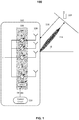
- FIG. 1 shows an exemplary three-dimensional beamforming system 100.
- the three-dimensional beamforming system 100 includes a wireless transmitter 102 and a terminal device 104.
- the wireless transmitter 102 may include a radio frequency (RF) phase shifter array 106, antenna array 108, and a control circuit 110.
- the phase shifter array 106 may include a codebook memory 112 having a set of codewords ⁇ stored therein.
- wireless transmitter 102 may utilize a codebook-based control approach in which control circuit 110 may provide the RF phase shifter array 104 with control signaling in the form of codeword (CW) indices.
- Control circuit 110 may select a codeword based on the direction or angle of a target point, such as by determining an optimal direction/angle estimation from a feedback signal 116 from a terminal device 104, and selecting the codeword that provides a direction or angle that most closely matches the preferred direction or angle indicated by the CSI of the received feedback signal 116.
- FIG. 1 depicts a specific implementation of a three-dimensional beamforming system 100, it should be noted that the disclosure is not limited to this illustrative system or the configuration therein.
- One of ordinary skill in the art will recognize that other types of beamforming systems having a different number of components, elements, architectures and/or arrangements thereof are contemplated by this disclosure.
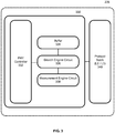
- FIG. 2 shows an exemplary configuration 200 of a terminal device 104.
- the terminal device 104 may include antenna system 222, RF transceiver 224, baseband modem 226, and application processor 228.
- Terminal device 102 may have one or more additional components not explicitly depicted in FIG. 2 , such as additional hardware, software, and/or firmware elements including processors, microprocessors, controllers, microcontrollers, memory, and/or other specialty or generic hardware, processors, circuits, etc., in order to support a variety of additional operations.
- Terminal device 104 may also include a variety of user input/output devices (display(s), keypad(s), touchscreen(s), speaker(s), external button(s), camera(s), microphone(s), etc.), peripheral device(s), memory, power supply, external device interface(s), subscriber identify module(s) ("SIM”), etc.
- user input/output devices display(s), keypad(s), touchscreen(s), speaker(s), external button(s), camera(s), microphone(s), etc.
- peripheral device(s) memory, power supply, external device interface(s), subscriber identify module(s) ("SIM”), etc.
- SIM subscriber identify module
- terminal device 104 may be configured to transmit and/or receive wireless signals according to one or more wireless access protocols or RATs, including any one or combination of 5G, LTE, WLAN, Wi-Fi, UMTS, GSM, Bluetooth, CDMA, WCDMA, etc.
- the RAT capabilities of terminal device 104 may be determined by one or more SIMs included in terminal device 104 (not explicitly shown).
- antenna system 222, RF transceiver 224, and baseband modem 226 may each respectively be an antenna system, RF transceiver system, and a baseband modem system composed of the individual dedicated components.
- one or more components of the terminal device 104 may be shared between different wireless access protocols, such as, e.g., by sharing antenna system 222 between multiple different wireless access protocols, e.g. by using a common RF transceiver 224 shared between multiple wireless access protocols, e.g. a common baseband modem 226 shared between multiple wireless access protocols, etc.
- RF transceiver 224 and/or baseband modem 226 may be operated according to multiple mobile communication access protocols (i.e., "multi-mode"), and thus may be configured to support one or more of LTE, UMTS, and/or GSM access protocols.
- RF transceiver 224 may receive radio frequency wireless signals via antenna system 222, which may be implemented as, e.g., a single antenna or an antenna array composed of multiple antennas.
- RF transceiver 224 may include various reception circuitry components, which may include analog circuitry configured to process externally received signals such as, e.g., mixing circuity to convert externally received RF signals to baseband and/or intermediate frequencies.
- RF transceiver 224 may also include amplification circuitry to amplify externally received signals, such as power amplifiers ("PA”s) and/or Low Noise Amplifiers ("LNA”s), although it is appreciated that such components may also be implemented separately from RF transceiver 224.
- RF transceiver 224 may additionally include various transmission circuitry components configured to transmit internally received signals, such as, e.g., baseband and/or intermediate frequency signals provided by baseband modem 226, which may include mixing circuitry to modulate internally received signals onto one or more radio frequency carrier waves and/or amplification circuitry to amplify internally received signals before transmission.
- RF transceiver 224 may provide such signals to antenna system 222 for wireless transmission.
- RF transceiver 224 may be additionally be connected to application processor 228.
- FIG. 3 shows an exemplary internal configuration of a baseband modem 226.
- baseband modem 226 may include a physical layer ("PHY," Layer 1) subsystem 330 and a protocol stack (Layers 2 and 3) subsystem 340.
- PHY physical layer
- Layer 3 protocol stack
- baseband modem 226 may additionally include various additional baseband processing circuitry, such as Analog to Digital Converters ("ADC”s) and/or Digital to Analog Converters (DACs), modulation/demodulation circuitry, encoding/decoding circuitry, audio codec circuitry, digital signal processing circuitry, etc.
- ADC Analog to Digital Converters
- DACs Digital to Analog Converters
- Baseband modem 226 may be responsible for mobile communication functions of terminal device 104, and may be configured to operate in conjunction with RF transceiver 224 and antenna system 222 to transmit and receive mobile communication signals in accordance with various mobile communication protocols.
- Baseband modem 226 may be responsible for various baseband signal processing operations for both uplink and downlink signal data. Accordingly, baseband modem 226 may obtain and buffer baseband downlink and uplink signals and subsequently provide the buffered downlink signals to various internal components of baseband modem 226 for respective processing operations.
- PHY subsystem 330 may be configured to perform control and processing of physical layer mobile communication functions, including error detection, forward error correction encoding/decoding, channel coding and interleaving, physical channel modulation/demodulation, physical channel mapping, radio measurement and search, frequency and time synchronization, antenna diversity processing, power control and weighting, rate matching, retransmission processing, etc.
- PHY subsystem 330 may include signal buffer 334, which may be a memory component configured to hold digital signal samples, e.g., as obtained via RF transceiver 224 or protocol stack subsystem 340.
- Search engine 336, measurement engine 338, and additional signal processing components of PHY subsystem 330 may be configured to access signal buffer 334 and process the baseband digital samples according to the corresponding signal processing functions of the respective components.
- Buffer 334 is represented as a single component in FIG. 3 for simplicity, and alternatively each component or given groups of components may have a dedicated buffer to hold digital signal samples for processing.
- the aforementioned functionality of PHY subsystem 330 may be realized as hardware and/or software (program code executed on a processor) components under the control of PHY controller 330. Skilled persons will appreciate the ability to implement the algorithmic, control, and I/O logic for such signal processing operations as either hardware or software logic with substantially equivalent functionality.
- PHY subsystem 330 may additionally include a non-transitory computer readable medium to store program code for retrieval by PHY controller 332, search engine circuit 336, measurement engine circuit 338, and other processors of PHY subsystem 330.
- PHY controller 332 may be implemented as a processor configured to execute physical layer control software and control the various components of PHY subsystem 330 under the direction of the control logic defined therein in order to provide the requisite physical layer functionality to terminal device 104.
- PHY controller 332 may be configured to control measurement engine 338 to perform cell search and measurement procedures.
- Baseband modem 226 may additionally include protocol stack subsystem 340, which may be responsible for the Layer 2 and Layer 3 functionality of the protocol stack.
- protocol stack subsystem 340 may be responsible for Medium Access Control (“MAC”), Radio Link Control (“RLC”), Packet Data Convergence Protocol (“PDCP”), Radio Resource Control (“RRC”), Non-Access Stratum (“NAS”), and Internet Protocol (“IP”) entity processes.
- MAC Medium Access Control
- RLC Radio Link Control
- PDCP Packet Data Convergence Protocol
- RRC Radio Resource Control
- NAS Non-Access Stratum
- IP Internet Protocol
- Protocol stack subsystem 340 may be implemented as a processor configured to execute protocol stack software and control mobile communication operations of terminal device 104 under the direction of control logic defined therein.
- Protocol stack subsystem 340 may interact with PHY subsystem 330, such as via an interface with PHY controller 332, to request physical layer services as specified by the protocol stack control logic including physical layer configuration and radio measurement.
- Protocol stack subsystem 340 may supply PHY subsystem 330 with downlink transport channel data (MAC data) scheduled for subsequent physical layer processing and transmission by PHY subsystem 330 (via RF transceiver 224 and antenna system 222 ).
- PHY subsystem 330 may conversely receive uplink physical channel data via (via RF transceiver 224 and antenna system 222 ) and perform subsequent physical layer processing on the received uplink physical channel data before providing the uplink physical channel data to protocol stack subsystem 340 as uplink transport channel data (MAC data).
- MAC data downlink transport channel data
- Baseband modem 226 may additionally interface with application processor 228.
- application processor 228 may be implemented as a Central Processing Unit ("CPU") and configured to execute various applications and/or programs of terminal device 104, such as, e.g., applications corresponding to program code stored in a memory component of terminal device 104 (not explicitly shown in FIG. 2 ).
- Application processor 228 may be configured to run an operating system ("OS") of terminal device 104, and may utilize the interface with baseband modem 226 in order to transmit and receive user data such as voice, video, application data, basic Internet/web access data, etc.
- OS operating system
- Application processor 228 may also be configured to control one or more further components of terminal device 104, such as user input/output devices (display(s), keypad(s), touchscreen(s), speaker(s), external button(s), camera(s), microphone(s), etc.), peripheral devices, memory, power supply, external device interfaces, etc.
- user input/output devices display(s), keypad(s), touchscreen(s), speaker(s), external button(s), camera(s), microphone(s), etc.
- peripheral devices memory, power supply, external device interfaces, etc.
- Terminal device 104 may transmit and receive data with various network cells, according to the protocol stack and physical layer operations directed by physical layer subsystem 330 and protocol stack subsystem 340.
- PHY controller 332 may be configured to control measurement engine 338 to perform cell measurement procedures including those related to channel quality.
- FIG. 4 shows an exemplary trend of channel quality metric variations in a three-dimensional beamforming system. More specifically, a surface graph 400 depicted therein illustrates a snapshot of the mutual information (MI) variation with respect to two orthogonal dimensions of a beam space of an exemplary LTE FD-MIMO Class A configuration.
- MI mutual information
- i 1,1 and i 1,2 represent two beam indexes corresponding to two orthogonal dimensions configured by the network.
- channel quality metric values can exhibit a degree of correlation over the beam space as the beam resolution becomes finer and the number of antenna elements increases.
- a first implementation of the disclosure relates to an efficient beam search operation at a receiver of a beamforming system.
- the beamforming system of the first implementation may be the three-dimensional beamforming system 100 of FIG. 1 , which includes the terminal device 104 as the receiver.
- the disclosure is not limited thereto.
- terminal device 104 may utilize a channel quality metric that is more computationally efficient for each individually tested beam candidate than other metrics, such as MI, in estimating a preferred beam direction for CSI feedback.
- channel quality metrics may include channel power and/or proximity to a unitary basis matrix of the channel. While these metrics may involve less computation than MI, which is better suited with respect to capacity, they do not necessarily correspond to reception performance.
- the approach of employing suboptimal metrics - while certainly useful - does not address the fundamental dependency of the computation load being based on the number of candidate beams. While the channel quality metrics of the first implementation may reduce the computation for each tested beam candidate, these channel quality metrics may be characterized as being less accurate than other metrics.
- the first implementation of the disclosure may be combined with the following class of beam search methods for devices in three-dimensional beamforming systems.
- the number of beam candidates may be reduced via coarse-to-fine subsampling of beam indices utilizing one or more aspects of the beam search techniques described herein.
- a multi-step subsampling and gradual localization of a beam space may be characterized as a branch-and-bound decision process.
- the branch-and-bound decision process may, in some aspects, include heuristics in conjunctions with the implementations discussed herein.
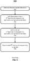
- FIG. 5 shows a flow diagram for a second implementation of the disclosure.
- the second implementation of the disclosure relates to a branching operation 550, which may be executed at a receiver of a three-dimensional beamforming system.
- the receiver such as terminal device 104, may be configured to estimate a channel spatial coherence of the beam space ⁇ using one of various methodologies.
- the channel spatial coherence is a correlation in a channel quality metric between two candidate beams. This correlation may provide a measure of the relationship between signals received by two antennas fed by the same source situated at different points in space.
- this correlation may be a modeled as a function of signal conditions, such as the angle of arrival, the power azimuth spectrum (PAS), antenna spacing and the system bandwidth.
- a pair of beams may exhibit a higher spatial coherence.
- an estimate of the channel spatial coherence may be used to determine parameters of both the branching and bounding procedure described herein. For instance, the resolutions of a 1 st level split and a final level split in branching and/or the number of survivors at each level in bounding may be derived from an estimated channel spatial coherence.
- the receiver may utilize a parametric approach.
- Parametric approaches generate a MIMO channel matrix based on a geometric description of the propagation environment (e.g., ray-tracing techniques).
- the receiver may utilize a non-parametric approach based on a given model (e.g., the Kronecker model).
- the spatial coherence of the beam space ⁇ may be characterized by one or more parameters, such as a "hill."
- a hill may be referred to as a distinct local region of the beam space ⁇ that includes a group of adjacent beams.
- Each of the beams of this distinct local region may have relatively higher channel quality values associated therewith.
- a beam that achieves the highest MCS within a distinct local rejection may thus be referred to as a channel quality "peak" herein, in each hill.
- the spatial coherence of the beam space ⁇ may be characterized by three parameters: (i) the average size of channel quality hills; (ii) the average number of distinct hills; and (iii) the average size of groups of adjacent beams in a hill, whose channel quality metric values lead to the same MCS as that of the peak of the hill.
- the set of these three parameters depends on the configuration of the beamforming system and the actual channel quality metric employed.
- these parameters may be deduced from empirical observations at a receiver.
- its parametric relationship with channel correlations may be established by modeling them as functions of an average pair-wise correlation of the selected channel quality metrics or, for an even simpler model, as functions of transmitter and receiver antenna correlations.
- the hills whose peak metric values correspond to a similar MCS as that of the global optimum may be considered of interest.
- the first and the third parameters may be used to determine the resolutions of the 1 st level split and/or the final level split, respectively, while the second parameter may be used as an upper bound on the number of survivors at each level.
- the channel spatial coherence may be estimated based on the non-precoded reference signals from the transmitter.
- the terminal device 104 may be configured to receive a plurality of non-precoded reference signals at antenna system 222.
- the terminal device 104 may be further configured to compute a variety of channel quality metrics from the non-precoded reference signals received therein. These channel quality metrics may be determined based on an instantaneous channel realization, a time-averaged channel realization, and/or updates thereof, which may be determined locally. Additionally or alternatively, one or more channel quality metrics may be forwarded by another device, such as over a D2D link to the terminal device 104 when they are within a predetermined proximity of each other.
- the terminal device 104 may be configured to estimate the channel spatial coherence of the beam space ⁇ based on angle of arrival information, the power PAS, receiver antenna spacing and/or system bandwidth.
- channel spatial coherence While various methodologies are described to estimate channel spatial coherence, other parametric and non-parametric approaches may be utilized. For instance, other estimates based on a minimum expected spatial coherence, the Kronecker model, the Weichselberger model, majorization, a uniform linear array, a uniform circular array, etc. may be employed at the terminal device 104 depending upon the design of a particular beamforming system.
- the branching procedure may execute in terminal device 104 to recursively construct or define N sets of subspaces of the beam space ⁇ , one set per level, so that there is a set S n of subspaces for the n th level, where n ⁇ ⁇ 1, ..., N ⁇ , N ⁇ 2 .
- the elements of S n are referred to herein as n th level subspaces.
- S ⁇ S n we have S ⁇ ⁇ .
- Branching may be performed by the terminal device 104 via a fixed construction or adaptive construction of S n .
- branching may be performed only once and independent of an instantaneous channel realization.
- branching may be based on a minimum expected spatial coherence for a given beamforming system, which is in some aspects may be determined by, or read from a memory of the terminal device 104.
- S n may be constructed by the terminal device 104 in adaptive manner, such as based on one or more time-varying spatial coherence estimates.
- the branching procedure may split the beam space ⁇ into a plurality of subspaces to construct S 1 .
- S 1 may recursively split into sets of smaller and smaller subspaces resulting in S n at 556, until in the N th iteration S N is reached at 558.
- Each iteration of the splitting and the resultant subspaces are associated with a level n ⁇ ⁇ 1, ... , N ⁇ .
- the first split yields a set of 1 st level subspaces
- the second split yields a set of 2 nd level subspaces, and so on.
- the size of the subspaces may be determined by parameters of the branching procedure.
- the size of 1 st level subspace and the size of a N th level subspace may be determined by the first and the third parameters of the branching procedure, respectively.
- the resolution of 1 st level split and the resolution of the final level split may be determined by design parameters of the branching procedure.
- the size of 1 st level subspace at 554 reflects a macroscopic trend of channel quality variation over the beam space ⁇ .
- the 1 st level split may employ the coarsest resolution that can still identify distinct local regions (i.e., groups of adjacent beams) of relatively higher channel quality values, i.e., hills.
- the N th level subspace size at 558 reflects a microscopic trend of channel quality variation over the beam space ⁇ .
- the final level split may employ the coarsest resolution that can still identify a beam that achieves the highest MCS, i.e., the channel quality peak in each hill.
- the identified beam does not have to be the true peak with the highest channel quality metric value. Rather, it is sufficient to have the identified beam as a beam whose associated channel quality metric value leads to the same MCS as that of the true peak.
- the number of branching iterations, or levels, can be derived by the terminal device 104 from two of the resolutions and the beam space ⁇ .
- each subspace S ⁇ S n for n ⁇ N is associated with a non-empty set F n +1 ( S ) ⁇ S n +1 of subspaces that will be considered when S is not pruned.
- the sets S n are constructed such that their subspaces are mutually disjoint ("non-overlapping"), then two different (and thus disjoint) subspaces S and S' ⁇ S n imply disjoint F ( S ) and F n +1 ( S' ) as well.
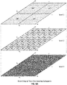
- FIGS. 6A - 6B respectively show branching procedures according to third and fourth implementations of the disclosure.
- FIG. 6A shows a branching procedure according to a third implementation of the disclosure.
- FIG. 6A relates to a branching procedure having non-overlapping subspaces of the beam space ⁇ .
- the illustrated branching procedure is a 3-level branching procedure producing 1 st level non-overlapping subspaces, 2 nd level non-overlapping subspaces, and 3 rd level non-overlapping subspaces of a beam space ⁇ .
- the indices b 1 and b 2 correspond to two orthogonal dimensions of the beam space ⁇ .
- a candidate beam may be uniquely identified as a distinct ( b 1 , b 2 ) ⁇ ⁇ and is represented by a dotted-line rectangle.
- a thick-solid rectangle represents a subspace comprising a dark-shaded beam as the representative beam of the subspace (i.e., node of the 3D tree).
- each subspace may further comprise at least one candidate beam.
- FIG. 6B it should be noted that each of the subspaces are shown in FIG. 6A .
- FIG. 6B shows a branching procedure according to a fourth implementation of the disclosure.
- FIG. 6B relates to a branching procedure having two overlapping 1 st level subspaces of the beam space ⁇ .
- the illustrated branching procedure is a 3-level branching procedure producing 1 st level overlapping subspaces, 2 nd level overlapping subspaces, and 3 rd level non-overlapping subspaces of a beam space ⁇ .
- the indices b 1 and b 2 correspond to two orthogonal dimensions of the beam space ⁇ .
- a candidate beam may be uniquely identified as a distinct ( b 1 , b 2 ) ⁇ ⁇ and is represented by a dotted-line rectangle.
- a thick-solid rectangle represents a first subspace whereas a thick-dashed line represents a second subspace in each level.
- Each of the first and second subspaces comprise a dark-shaded beam that is the representative beam of the subspace.
- each of the first and second subspaces may further comprise at least one candidate beam.
- FIG. 6A it should be noted that only two subspaces per level are shown in FIG. 6B to better illustrate the relationship between subspaces and how the size of the subspaces shrinks as branching level increases.
- the number of levels of branching, subspaces of each level, beams within a subspace, and/or number of levels having overlapping subspaces depicted in FIGS. 6A - 6B is purely illustrative in nature. Although the subspaces have been classified as either being overlapping or non-overlapping in each level, it further contemplated by the disclosure that some subspaces of an n th level may overlap, whereas other subspaces may not. In FIG. 6B , for instance, the first and second subspaces of the 2 nd level are non-overlapping. It further should be noted that while the 3 rd level or N th level subspaces illustrated in FIGS. 6A - 6B include one representative beam, this is not always the case. A subspace of the final level may include other beams in addition to the representative beam depending upon, for instance, the degree of channel spatial coherence. Stated differently, the granularity of the final level subspaces may vary with the channel spatial coherence.
- FIG. 7 shows a flow diagram for a fifth implementation of the disclosure.
- the fifth implementation of the disclosure relates to a bounding procedure 770, which may be executed at a receiver of a three-dimensional beamforming system.
- Bounding procedure 770 may be viewed herein as a search spanning N levels, which may be utilized to reduce the number of candidate beams tested. This search may comprise an M number of stages, where m ⁇ ⁇ 1 , ..., M ⁇ .
- the bounding procedure 770 may remove (i.e., prune) subspaces whose representative channel quality metric value is "out of bounds" (e.g., below a certain bound) for a respective level and/or stage.
- the bounding procedure 770 of FIG. 7 is implemented as a breadth-first search of a tree structure. Breadth-first searches may consider all surviving nodes of a given level before moving on to the next level. Surviving nodes may be referred herein as "survivors," which, at level n , are subspaces S ⁇ S n .
- the terminal device 104 may perform a channel observation procedure.
- the terminal device 104 may be configured to receive and measure a plurality of non-precoded reference signals at antenna system 222. These channel observations may be based on an instantaneous channel realization, a time-averaged channel realization, and/or updates thereof, which may be determined locally. Additionally or alternatively, one or more channel observations may be forwarded by another device, such as over a D2D link to the terminal device 104 when they are within a predetermined proximity of each other.
- the terminal device 104 may be configured to compute a channel quality metric from the non-precoded reference signals for each of the subspaces of the 1 st level and/or stage. One or more of these channel quality metrics may be computed and/or determined from the channel observations described in 771.
- the terminal device 104 may be configured to select at least one survivor subspace based on a bound for the 1 st level subspace and/or 1 st stage.
- the terminal device 104 may be configured to determine a channel quality metric from the non-precoded reference signals for each of the subspaces of the n th level and/or m th stage. One or more of these channel quality metrics may be computed and/or determined from the channel observations described in 771.
- the terminal device 104 may be configured to select at least one survivors based on a bound for the n th level subspace and/or m th stage.
- the terminal device 104 may be configured to determine a channel quality metric from the non-precoded reference signals for each of the subspaces of the N th level subspace and/or M th stage.
- One or more of the channel quality metrics may be computed and/or determined from the channel observations described in 771.
- the terminal device 104 may be configured to select a beam with the highest channel quality metric of the 1 st level - N th level subspace and/or 1 st - M th stage.
- the bounding procedure 770 of FIG. 7 may be better understood by way of comparison to the branching procedure 550 of FIG. 5 .
- the branching procedure 550 may be viewed as generating a three-dimensional N -level tree structure of beam candidates.
- Bounding procedure 770 may be viewed as an M -stage search over the tree, where a stage is defined as the evaluation of the subspaces in F n +1 ( S ) for a S ⁇ S n .
- the bounding procedure 770 of FIG. 7 is implemented as a breadth-first bounding procedure, it should be noted that other types of searches including best-first and depth-first searches are possible. Likewise, many graph search algorithms can be adapted in the bounding procedure, since the beam space ⁇ may be translated into a tree structure via the branching procedure 550.
- the number of stages M may be pre-determined or variable.
- a variable M may depend on the bound, and/or a limit on maximum M can be imposed by a variety of early stopping schemes.
- early stopping rules can be enforced for shorter searches, via a threshold on the current maximum metric, a threshold on the difference between the current maximum and other values, a fixed number of steps, etc.
- the bound itself may be pre-determined or adaptive.
- An adaptive bound for instance, may be updated with a new set of channel observations or updated at each stage of bounding.
- the bound may be referred to herein as a threshold channel quality metric.
- the threshold channel quality metric may be defined with respect to a particular level of the subspaces. For instance, a channel quality metric value that is representative of a candidate subspace may be compared to a threshold channel quality metric of a particular level of the subspaces. Additionally or alternatively, the threshold channel quality metric may be defined with respect to the particular stage of the bounding procedure 770. For example, the channel quality metric value that is representative of a candidate subspace may be compared to an adaptive threshold channel quality metric that is updated at each stage and/or is a fraction of the highest channel quality metric value found so far in the search.
- FIGS. 8A - 8B respectively show bounding procedures according to sixth and seventh implementations of the disclosure.
- FIG. 8A shows a bounding procedure according to a sixth implementation of the disclosure.
- FIG. 8A relates to a breadth-first bounding procedure, which may be executed in a receiver (e.g., terminal device 104 ) of a three-dimensional beamforming system. More specifically, the bounding procedure illustrated therein spans the 3-level three-dimensional tree with overlapping subspaces. In this case, the two subspaces outlined in bold for each level do not overlap with each other.
- the indices b 1 and b 2 correspond to two orthogonal dimensions of the beam space ⁇ .
- a candidate beam may be uniquely identified as a distinct ( b 1 , b 2 ) ⁇ ⁇ and is represented by a dotted-line rectangle.
- a thick-solid rectangle represents a subspace comprising a dark-shaded beam as the representative beam of the subspace.
- each subspace may further comprise at least one candidate beam. It should be noted that any two nodes with the same number indicators may be considered in any order.
- all subspaces in each level may be considered by the terminal device 104 before moving onto the next level. That is, the channel quality metrics m ( S 1 ) of all level 1 subspaces S 1 ⁇ S are computed. Then, a lower bound ⁇ . max ( m ( S 1 )), 0 ⁇ ⁇ ⁇ 1 , may be used to prune the level 1 subspaces, two of which survive in this example. Each survivor maps to nine level 2 subspaces S 2 ⁇ F 2 ( S 1 ), thus 18 channel quality metrics m ( S 2 ) are computed in the next stage.
- FIG. 8B shows a bounding procedure according to a seventh implementation of the disclosure.
- FIG. 8B relates to a best-first bounding procedure, which may be executed in a receiver (e.g., terminal device 104 ) of a three-dimensional beamforming system. More specifically, the bounding procedure illustrated therein spans the 3-level three-dimensional tree with overlapping subspaces. Like FIG. 8A , the two subspaces outlined in bold for each level do not overlap with each other.
- FIG. 8B The three-dimensional tree of FIG. 8B is the same as that described in FIG. 8A . Thus, its description is omitted. It, however, should be noted that any two nodes with the same number indicators may be considered in any order.
- the children subspaces of a parent subspace with higher channel quality metric value are considered by the terminal device 104 first, regardless of the level.
- the level 1 survivor S 1A indicated by 1A, is associated with higher channel quality metrics m ( S 1 ) than the survivor S 1B .
- the level 2 subspaces of S 1A are considered first. If max ( m ( S 2
- FIGS. 9A - 9B respectively show branching and bounding methods according to the eighth and ninth implementations of the disclosure.
- FIG. 9A shows a branching and bounding method according to the eighth implementation of the disclosure.
- the method comprises: estimating a channel spatial coherence for a beam space of a terminal device based on a plurality of non-precoded reference signals, the beam space comprising a plurality of beam subspaces based on the estimated channel spatial coherence, each of the beam subspaces including a beam direction that is representative of a respective beam subspace of the beam subspaces 992; and selecting, by the terminal device, a beam subspace of the beam subspaces based on a channel quality metric of the beam direction that is representative of the selected beam subspace 994.
- FIG. 9B shows a branching and bounding method according to the ninth implementation of the disclosure.
- the method comprises: estimating a channel spatial coherence for a beam space of a terminal device based on a plurality of non-precoded reference signals, the beam space comprising a plurality of beam subspaces based on the estimated channel spatial coherence, each of the beam subspaces including a beam direction that is representative of a respective beam subspace of the beam subspaces 996, selecting, by the terminal device, a beam subspace of the beam subspaces based on a channel quality metric of the beam direction that is representative of the selected beam subspace 997, and generating, by the terminal device, a feedback signal indicating the beam direction that is representative of the selected beam space 998.
- FIG. 10 shows a circuit configuration 1000 according to a tenth implementation of the disclosure.
- the circuit configuration may be implemented within a receiver of a three-dimensional beamforming system.
- the circuit configuration may include a channel observation circuit 1002, an estimation circuit 1004, a branching circuit 1006, a bounding circuit 1008, a selection circuit 1010, a processing circuit 1012, and memory 1014.
- a particular circuit configuration is illustrated, the present disclosure is not limited to this illustrative example.
- circuit configuration 1000 may optionally include one or more elements or functions described with respect to terminal device 104.
- the channel observation circuit 1002 may be configured to receive the non-precoded reference signals at a plurality of receiver antennas of the terminal device.
- the estimation circuit 1004 may be configured to estimate a channel spatial coherence for a beam space of a terminal device based on a plurality of non-precoded reference signals.
- the branching circuit 1006 may be configured to define each of the beam subspaces to comprise a plurality of beam directions including the beam direction that is representative of the respective beam subspace, each of the beam directions having a channel quality metric associated therewith that is within a threshold range of the respective beam subspace.
- the bounding circuit 1008 may be configured to reduce a number of the beam subspaces that may be selected by the selection circuit based on a comparison of the channel quality metric of the beam direction that is representative of the identified beam subspace and a threshold channel quality metric of the beam subspaces.
- the selection circuit 1010 may be configured to select a beam subspace of the beam subspaces based on a channel quality metric of the beam direction that is representative of the selected beam subspace.
- the processing circuit 1012 may be configured to generate a feedback signal indicating the beam direction that is representative of the selected beam space. Furthermore, one or more of the disclosed circuits 1002-1012 may be implemented by one or more the processors of the disclosure (e.g., application processor 228 ), whereas memory 1014 may be implemented by one or more the memory elements of the disclosure (e.g., buffer 334 ).
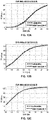
- FIGS. 11 - 13 show a comparison of the throughput performance for an illustrative beamforming system and an exhaustive search.
- FIGS. 11 -13 depict a comparison of the throughput performance of an LTE FD-MIMO Class A system achieved through (i) an exhaustive search of the beam space ⁇ and (ii) an illustrative implementation of the disclosure.
- CSI-RS Channel State Information-Reference Signal
- UE User Equipment
- FIGS. 11 - 13 depict throughput (TP) performance in Megabits per second (Mbps) with respect to the signal-to-noise ratio (SNR) in decibels (dB) for a respective multipath fading propagation condition.
- FIGS. 11A - 11C correspond to an Extended Pedestrian A (EPA) delay profile.
- FIGS. 12A - 12C correspond to an Extended Vehicular A (EVA) delay profile.
- FIGS. 12A - 12C correspond to an Extended Typical Urban (ETU) delay profile.
- FIGS. 11 - 13 also depict TP performance in Mbps with respect to the SNR in dB for a respective correlation levels between transmit and receive antennas.
- FIGS. 11B , 12B , and 13B correspond to a medium level of correlation having a MIMO channel correlation parameters of ( 0.2, 0.2, 0.6, 0.3 ).
- FIGS. 11C , 12C , and 13C correspond to a high level of correlation having a MIMO channel correlation parameters of ( 0.9, 0.9, 0.9, 0.3 ).
- FIGS. 11 - 13 further depict a dashed curve representing the exhaustive search of the beam space ⁇ and a solid curve representing the second aspect of the disclosure.
- the exhaustive search of the beam space ⁇ considers all 512 beam candidates, whereas the particular implementation of the disclosure considers up to 59 beam candidates.
- the illustrative implementation of the disclosure employs a branch-and-bound search method, in which the beam space ⁇ is translated into a 3 -level tree structure.
- the first implementation of the disclosure employs channel quality metrics that reduces the computation for each of the tested hypotheses.
- the branch-and-bound beam search methods may reduce the computational load at the receiver by directly reducing the number of tested beam hypotheses.
- the proposed subsampling approach may be used in conjunction with the approach detailed in the first implementation. Together, the receiver computation load can be reduced even further than what is achievable with only one of the methods.
- the branch-and-bound beam search methods are described as heuristic branch-and-bound, in the sense that they do not always find the true optimum, but rather aim to reach an approximate solution that may or may not be a local or a global optimum.
- This potential suboptimality of the proposed methods arises because, in general, the globally optimum channel quality metric can only be found via an exhaustive search over the whole beam space. That is, strictly speaking, the set of per-beam channel quality metrics cannot always be characterized by a smaller set. For instance, a beamforming system may be designed such that the minimum expected spatial coherence is zero. This is different from approach of the first implementation whose suboptimality comes from the channel quality metric itself.
- the suboptimality of the proposed methods can be insignificant over a wide range of operation scenarios. This is because in practice, (i) a beam space tends to exhibit significant spatial coherence, and (ii) the impact of a difference in channel quality metric on the observable performance is de-sensitized due to a system constraint on the number of MCS levels.
- three-dimensional beamforming systems by intention support narrow beamwidth via a large number of antenna elements, whose form factor constraints translate to higher antenna correlation than in traditional communication systems.
- the CSI corresponding to MCS can only be represented with a finite number of bits (e.g. 4 bits and 16 MCS levels in LTE), and thus a calculated estimate often achieves a similar link-adapted throughput performance as the optimum beam choice.
- the branch and bound implementations of the disclosure may be used to determine and provide CSI feedback by a receiver (e.g., terminal device 104 ) more efficiently than the first implementation of the disclosure. Together, however, the receiver computation load can be reduced even further than what is achievable with only one of the methods.
- a receiver e.g., terminal device 104
- the receiver computation load can be reduced even further than what is achievable with only one of the methods.
- an unrestricted beam space can span hundreds and even thousands of beam candidates in current and future-generation three-dimensional beamforming systems with non-precoded reference signals.
- the number of tested beam candidates in a global codebook sweep may be reduced by an order of magnitude.
- a reduction in associated hardware run-time, power consumption, and/or hardware size may be realized due to the reduction in number of beam candidates.
- a device corresponding to a method detailed herein may include one or more components configured to perform each aspect of the related method.
- first, second, third, etc. may be used herein to describe various elements, components, regions, layers and/or sections, these elements, components, regions, layers and/or sections should not be limited by these terms. These terms may be only used to distinguish one element, component, region, layer or section from another. Terms such as “first,” “second,” and other numerical terms when used herein do not imply a sequence or order unless clearly indicated by the context. Thus, a first element, component, region, layer or section discussed below could be termed a second element, component, region, layer or section without departing from the teachings of the example aspects.
Landscapes
- Engineering & Computer Science (AREA)
- Computer Networks & Wireless Communication (AREA)
- Signal Processing (AREA)
- Physics & Mathematics (AREA)
- Mathematical Physics (AREA)
- Power Engineering (AREA)
- Radio Transmission System (AREA)
- Mobile Radio Communication Systems (AREA)
Claims (12)
- Verfahren für dreidimensionale Strahlbildung, wobei das Verfahren Folgendes umfasst:Schätzen einer räumlichen Kanalkohärenz für einen Strahlraum einer Endgeräteinrichtung auf Grundlage einer Vielzahl nicht-vorcodierter Referenzsignale, wobei der Strahlraum eine Vielzahl von Strahlteilräumen umfasst,wobei jeder der Vielzahl von Strahlteilräumen eine einen jeweiligen Strahlteilraum der Vielzahl von Strahlteilräumen repräsentierende Strahlrichtung beinhaltet,durch die Endgeräteinrichtung erfolgendes Auswählen eines Strahlteilraums der Vielzahl von Strahlteilräumen auf Grundlage einer Kanalqualitätsmetrik der den Strahlteilraum repräsentierenden Strahlrichtung,Definieren der Vielzahl von Strahlteilräumen auf Grundlage der geschätzten räumlichen Kanalkohärenz und Durchführen einer Begrenzungsprozedur an der Vielzahl durch die Endgeräteinrichtung auswählbarer Strahlteilräume.
- Verfahren nach Anspruch 1, wobei das Definieren der Vielzahl von Strahlteilräumen aus dem Strahlraum Folgendes umfasst:Definieren jedes der Vielzahl von Strahlteilräumen so,dass sie eine Vielzahl jeweilige Strahlteilräume repräsentierender Strahlrichtungen umfassen,wobei jede der Vielzahl von Strahlrichtungen einer Kanalqualitätsmetrik innerhalb eines Grenzbereichs des jeweiligen Strahlteilraums zugeordnet wird.
- Verfahren nach einem der Ansprüche 1 oder 2, wobei das Definieren der Vielzahl von Strahlteilräumen aus dem Strahlraum Folgendes umfasst:
Definieren einer Vielzahl von Strahlteilräumen N-ten Grades aus jedem der Vielzahl von Strahlteilräumen auf Grundlage der geschätzten räumlichen Kanalkohärenz, wobei jeder der Vielzahl von Strahlteilräumen N-ten Grades eine einen jeweiligen Strahlteilraum N-ten Grades repräsentierende Strahlrichtung N-ten Grades beinhaltet. - Verfahren nach Anspruch 3, wobei das Definieren der Strahlteilräume N-ten Grades aus jedem der Vielzahl von Strahlteilräumen Folgendes umfasst:Definieren jedes der Vielzahl von Strahlteilräumen N-ten Grades so, dass er mindestens eine den jeweiligen Strahlteilraum N-ten Grades repräsentierende Strahlrichtung N-ten Grades umfasst,wobei jede der Vielzahl von Strahlrichtungen N-ten Grades einer Kanalqualitätsmetrik innerhalb eines Bereichs des jeweiligen Strahlteilraums N-ten Grades zugeordnet wird.
- Verfahren nach einem der Ansprüche 3 oder 4, ferner umfassend:
durch die Endgeräteinrichtung erfolgendes Auswählen eines Strahlteilraums N-ten Grades aus der Vielzahl von Strahlteilräumen N-ten Grades auf Grundlage einer Kanalqualitätsmetrik der den Strahlteilraum N-ten Grades repräsentierenden Strahlrichtung N-ten Grades. - Verfahren nach Anspruch 1, wobei das Durchführen der Begrenzungsprozedur Folgendes umfasst:
Identifizieren eines Strahlteilraums der Vielzahl von Strahlteilräumen auf Grundlage einer Kanalqualitätsmetrik der den identifizierten Strahlteilraum repräsentierenden Strahlrichtung. - Verfahren nach Anspruch 6, wobei das Durchführen der Begrenzungsprozedur Folgendes umfasst:
Vergleichen der Kanalqualitätsmetrik der den identifizierten Strahlteilraum repräsentierenden Strahlrichtung und einer Grenz-Kanalqualitätsmetrik der Vielzahl von Strahlteilräumen. - Verfahren nach Anspruch 7, wobei das Durchführen der Begrenzungsprozedur Folgendes umfasst:
Verringern einer Anzahl der Vielzahl durch die Endgeräteinrichtung auswählbarer Strahlteilräume auf Grundlage des Vergleichs. - Einrichtung für dreidimensionale Strahlbildung, wobei die Einrichtung Folgendes umfasst:eine Schätzschaltung, die dafür konfiguriert ist, eine räumliche Kanalkohärenz für einen Strahlraum einer Einrichtung auf Grundlage einer Vielzahl nicht-vorcodierter Referenzsignale zu schätzen, wobei der Strahlraum auf Grundlage der geschätzten räumlichen Kanalkohärenz eine Vielzahl von Strahlteilräumen umfasst, wobei jeder der Vielzahl von Strahlteilräumen eine einen jeweiligen Strahlteilraum repräsentierende Strahlrichtung beinhaltet,eine Auswahlschaltung, die dafür konfiguriert ist, einen Strahlteilraum der Vielzahl von Strahlteilräumen auf Grundlage einer Kanalqualitätsmetrik der den ausgewählten Strahlteilraum repräsentierenden Strahlrichtung auszuwählen,eine Verarbeitungsschaltung, die dafür konfiguriert ist, ein Rückkopplungssignal zu erzeugen, das die den Strahlraum repräsentierende Strahlrichtung anzeigt, undeine Begrenzungsschaltung, die konfiguriert ist, um eine Begrenzungsprozedur durchzuführen, die eine Anzahl der Vielzahl durch die Auswahlschaltung auswählbarer Strahlteilräume verringert.
- Einrichtung nach Anspruch 9, ferner umfassend:eine Verzweigungsschaltung, die dafür konfiguriert ist, jeden der Vielzahl von Strahlteilräumen so zu definieren, dass sie eine Vielzahl jeweilige Strahlteilräume repräsentierender Strahlrichtungen umfassen,wobei jede der Vielzahl von Strahlrichtungen einer Kanalqualitätsmetrik innerhalb eines Grenzbereichs des jeweiligen Strahlteilraums zugeordnet ist.
- Einrichtung nach Anspruch 10, wobei
die Verzweigungsschaltung ferner dafür konfiguriert ist, eine Vielzahl von Strahlteilräumen N-ten Grades aus jedem der Vielzahl von Strahlteilräumen auf Grundlage der geschätzten räumlichen Kanalkohärenz zu definieren, wobei jeder der Vielzahl von Strahlteilräumen N-ten Grades eine einen jeweiligen Strahlteilraum N-ten Grades repräsentierende Strahlrichtung N-ten Grades beinhaltet, und
die Auswahlschaltung ferner dafür konfiguriert ist, einen Strahlteilraum N-ten Grades aus der Vielzahl von Strahlteilräumen N-ten Grades auf Grundlage einer Kanalqualitätsmetrik der den Strahlteilraum N-ten Grades repräsentierenden Strahlrichtung N-ten Grades auszuwählen. - Einrichtung nach Anspruch 10, wobei der ausgewählte Strahlteilraum N-ten Grades aus der verringerten Anzahl der Vielzahl von Strahlteilräumen N-ten Grades ausgewählt ist.
Priority Applications (4)
| Application Number | Priority Date | Filing Date | Title |
|---|---|---|---|
| EP17164097.2A EP3382904B1 (de) | 2017-03-31 | 2017-03-31 | Effiziente strahlsuchverfahren zur dreidimensionalen strahlformung mit nicht vorcodierten referenzsignalen |
| CN201880022784.4A CN110476368A (zh) | 2017-03-31 | 2018-03-12 | 用于非预编码参考信号的三维波束赋形的有效波束搜索方法 |
| PCT/US2018/021912 WO2018182954A1 (en) | 2017-03-31 | 2018-03-12 | Efficient beam search methods for three-dimensional beamforming with non-precoded reference signals |
| US16/488,618 US11012132B2 (en) | 2017-03-31 | 2018-03-12 | Efficient beam search methods for three-dimensional beamforming with non-precoded reference signals |
Applications Claiming Priority (1)
| Application Number | Priority Date | Filing Date | Title |
|---|---|---|---|
| EP17164097.2A EP3382904B1 (de) | 2017-03-31 | 2017-03-31 | Effiziente strahlsuchverfahren zur dreidimensionalen strahlformung mit nicht vorcodierten referenzsignalen |
Publications (2)
| Publication Number | Publication Date |
|---|---|
| EP3382904A1 EP3382904A1 (de) | 2018-10-03 |
| EP3382904B1 true EP3382904B1 (de) | 2019-12-11 |
Family
ID=58464357
Family Applications (1)
| Application Number | Title | Priority Date | Filing Date |
|---|---|---|---|
| EP17164097.2A Active EP3382904B1 (de) | 2017-03-31 | 2017-03-31 | Effiziente strahlsuchverfahren zur dreidimensionalen strahlformung mit nicht vorcodierten referenzsignalen |
Country Status (4)
| Country | Link |
|---|---|
| US (1) | US11012132B2 (de) |
| EP (1) | EP3382904B1 (de) |
| CN (1) | CN110476368A (de) |
| WO (1) | WO2018182954A1 (de) |
Families Citing this family (2)
| Publication number | Priority date | Publication date | Assignee | Title |
|---|---|---|---|---|
| CN111093209B (zh) * | 2018-10-24 | 2023-03-10 | 深圳市太赫兹科技创新研究院 | 动态信号发射结构及波束赋形方法 |
| US20220399641A1 (en) * | 2021-02-09 | 2022-12-15 | The Johns Hopkins University | Phased array antenna with reduced node count |
Family Cites Families (6)
| Publication number | Priority date | Publication date | Assignee | Title |
|---|---|---|---|---|
| US5956642A (en) * | 1996-11-25 | 1999-09-21 | Telefonaktiebolaget L M Ericsson | Adaptive channel allocation method and apparatus for multi-slot, multi-carrier communication system |
| US8675748B2 (en) * | 2010-05-25 | 2014-03-18 | CSR Technology, Inc. | Systems and methods for intra communication system information transfer |
| US8923792B2 (en) * | 2012-07-05 | 2014-12-30 | Lg Electronics Inc. | Method for receiving radio signal and device therefor |
| CN103427893B (zh) * | 2013-08-31 | 2016-05-25 | 西安电子科技大学 | 一种两阶段码本搜索的三维波束赋形方法 |
| US9178588B2 (en) * | 2013-09-10 | 2015-11-03 | Intel IP Corporation | Method for determining a transmission direction for a communication, a method for determining a precoding matrix for a communication, and a device configured to do the same |
| US11082176B2 (en) * | 2016-11-04 | 2021-08-03 | Futurewei Technologies, Inc. | System and method for transmitting a sub-space selection |
-
2017
- 2017-03-31 EP EP17164097.2A patent/EP3382904B1/de active Active
-
2018
- 2018-03-12 US US16/488,618 patent/US11012132B2/en active Active
- 2018-03-12 WO PCT/US2018/021912 patent/WO2018182954A1/en active Application Filing
- 2018-03-12 CN CN201880022784.4A patent/CN110476368A/zh active Pending
Non-Patent Citations (1)
| Title |
|---|
| None * |
Also Published As
| Publication number | Publication date |
|---|---|
| CN110476368A (zh) | 2019-11-19 |
| US20200052755A1 (en) | 2020-02-13 |
| WO2018182954A1 (en) | 2018-10-04 |
| EP3382904A1 (de) | 2018-10-03 |
| US11012132B2 (en) | 2021-05-18 |
Similar Documents
| Publication | Publication Date | Title |
|---|---|---|
| KR102616419B1 (ko) | 무선 통신 시스템에서 안테나 구성에 기반한 빔 탐색 장치 및 방법 | |
| US11689261B2 (en) | Multiple beam multiple-input-multiple-output system | |
| US10014918B2 (en) | Systems and methods for beam selection for hybrid beamforming | |
| US10819414B2 (en) | Methods and devices for beam tracking | |
| KR101993967B1 (ko) | 안테나 배열체를 사용하는 빔 포밍 | |
| US10778294B2 (en) | Channel state information feedback method, terminal device, and network device | |
| US20220329289A1 (en) | Methods, distributed base station system, remote radio unit and base band unit system for handling uplink signals | |
| WO2018095305A1 (zh) | 一种波束训练方法及装置 | |
| US11190260B2 (en) | Beam estimation aided beam acquisition | |
| CN111587542A (zh) | 上报信道状态信息csi的方法和装置 | |
| WO2016183835A1 (zh) | 传输信号的方法和设备 | |
| CN111989876A (zh) | 用于无线通信系统的电子设备、方法和存储介质 | |
| US20200304194A1 (en) | Wireless communication apparatus for adaptive beamforming and method of operation thereof | |
| US8619612B2 (en) | Measurement and feedback calculation for wireless communication network | |
| US8929390B2 (en) | Methods and apparatuses for channel estimation in wireless networks | |
| US11012132B2 (en) | Efficient beam search methods for three-dimensional beamforming with non-precoded reference signals | |
| US10750547B2 (en) | Beamforming based on combined beams | |
| EP3526908B1 (de) | Relative uplink-kanalschätzung | |
| JP7003424B2 (ja) | 無線通信装置、方法及びプログラム | |
| US20230379193A1 (en) | Network node, user equipment, and methods in a wireless communications network | |
| US11245455B2 (en) | Wireless communication apparatus for low-complexity beamforming feedback and method of operating the apparatus | |
| WO2017193278A1 (zh) | Csi-rs的配置方法、csi的反馈方法、装置以及通信系统 | |
| CN117254889A (zh) | 波束信息的确定方法、装置及通信设备 |
Legal Events
| Date | Code | Title | Description |
|---|---|---|---|
| PUAI | Public reference made under article 153(3) epc to a published international application that has entered the european phase |
Free format text: ORIGINAL CODE: 0009012 |
|
| STAA | Information on the status of an ep patent application or granted ep patent |
Free format text: STATUS: REQUEST FOR EXAMINATION WAS MADE |
|
| 17P | Request for examination filed |
Effective date: 20170331 |
|
| AK | Designated contracting states |
Kind code of ref document: A1 Designated state(s): AL AT BE BG CH CY CZ DE DK EE ES FI FR GB GR HR HU IE IS IT LI LT LU LV MC MK MT NL NO PL PT RO RS SE SI SK SM TR |
|
| AX | Request for extension of the european patent |
Extension state: BA ME |
|
| RBV | Designated contracting states (corrected) |
Designated state(s): AL AT BE BG CH CY CZ DE DK EE ES FI FR GB GR HR HU IE IS IT LI LT LU LV MC MK MT NL NO PL PT RO RS SE SI SK SM TR |
|
| GRAP | Despatch of communication of intention to grant a patent |
Free format text: ORIGINAL CODE: EPIDOSNIGR1 |
|
| STAA | Information on the status of an ep patent application or granted ep patent |
Free format text: STATUS: GRANT OF PATENT IS INTENDED |
|
| INTG | Intention to grant announced |
Effective date: 20190704 |
|
| RIN1 | Information on inventor provided before grant (corrected) |
Inventor name: EDER, FRANZ Inventor name: JU, ZIYANG Inventor name: HWANG, YEONG-SUN YONGSUN |
|
| GRAS | Grant fee paid |
Free format text: ORIGINAL CODE: EPIDOSNIGR3 |
|
| GRAA | (expected) grant |
Free format text: ORIGINAL CODE: 0009210 |
|
| STAA | Information on the status of an ep patent application or granted ep patent |
Free format text: STATUS: THE PATENT HAS BEEN GRANTED |
|
| AK | Designated contracting states |
Kind code of ref document: B1 Designated state(s): AL AT BE BG CH CY CZ DE DK EE ES FI FR GB GR HR HU IE IS IT LI LT LU LV MC MK MT NL NO PL PT RO RS SE SI SK SM TR |
|
| REG | Reference to a national code |
Ref country code: GB Ref legal event code: FG4D |
|
| REG | Reference to a national code |
Ref country code: CH Ref legal event code: EP |
|
| REG | Reference to a national code |
Ref country code: AT Ref legal event code: REF Ref document number: 1213222 Country of ref document: AT Kind code of ref document: T Effective date: 20191215 |
|
| REG | Reference to a national code |
Ref country code: DE Ref legal event code: R096 Ref document number: 602017009504 Country of ref document: DE |
|
| REG | Reference to a national code |
Ref country code: IE Ref legal event code: FG4D |
|
| REG | Reference to a national code |
Ref country code: NL Ref legal event code: FP |
|
| REG | Reference to a national code |
Ref country code: LT Ref legal event code: MG4D |
|
| PG25 | Lapsed in a contracting state [announced via postgrant information from national office to epo] |
Ref country code: SE Free format text: LAPSE BECAUSE OF FAILURE TO SUBMIT A TRANSLATION OF THE DESCRIPTION OR TO PAY THE FEE WITHIN THE PRESCRIBED TIME-LIMIT Effective date: 20191211 Ref country code: LV Free format text: LAPSE BECAUSE OF FAILURE TO SUBMIT A TRANSLATION OF THE DESCRIPTION OR TO PAY THE FEE WITHIN THE PRESCRIBED TIME-LIMIT Effective date: 20191211 Ref country code: LT Free format text: LAPSE BECAUSE OF FAILURE TO SUBMIT A TRANSLATION OF THE DESCRIPTION OR TO PAY THE FEE WITHIN THE PRESCRIBED TIME-LIMIT Effective date: 20191211 Ref country code: NO Free format text: LAPSE BECAUSE OF FAILURE TO SUBMIT A TRANSLATION OF THE DESCRIPTION OR TO PAY THE FEE WITHIN THE PRESCRIBED TIME-LIMIT Effective date: 20200311 Ref country code: GR Free format text: LAPSE BECAUSE OF FAILURE TO SUBMIT A TRANSLATION OF THE DESCRIPTION OR TO PAY THE FEE WITHIN THE PRESCRIBED TIME-LIMIT Effective date: 20200312 Ref country code: BG Free format text: LAPSE BECAUSE OF FAILURE TO SUBMIT A TRANSLATION OF THE DESCRIPTION OR TO PAY THE FEE WITHIN THE PRESCRIBED TIME-LIMIT Effective date: 20200311 Ref country code: FI Free format text: LAPSE BECAUSE OF FAILURE TO SUBMIT A TRANSLATION OF THE DESCRIPTION OR TO PAY THE FEE WITHIN THE PRESCRIBED TIME-LIMIT Effective date: 20191211 |
|
| PG25 | Lapsed in a contracting state [announced via postgrant information from national office to epo] |
Ref country code: RS Free format text: LAPSE BECAUSE OF FAILURE TO SUBMIT A TRANSLATION OF THE DESCRIPTION OR TO PAY THE FEE WITHIN THE PRESCRIBED TIME-LIMIT Effective date: 20191211 Ref country code: HR Free format text: LAPSE BECAUSE OF FAILURE TO SUBMIT A TRANSLATION OF THE DESCRIPTION OR TO PAY THE FEE WITHIN THE PRESCRIBED TIME-LIMIT Effective date: 20191211 |
|
| REG | Reference to a national code |
Ref country code: DE Ref legal event code: R081 Ref document number: 602017009504 Country of ref document: DE Owner name: APPLE INC., CUPERTINO, US Free format text: FORMER OWNER: INTEL IP CORPORATION, SANTA CLARA, CALIF., US Ref country code: DE Ref legal event code: R081 Ref document number: 602017009504 Country of ref document: DE Owner name: APPLE INC., CUPERTINO, US Free format text: FORMER OWNER: INTEL IP CORPORATION, SANTA CLARA, CA, US |
|
| PG25 | Lapsed in a contracting state [announced via postgrant information from national office to epo] |
Ref country code: AL Free format text: LAPSE BECAUSE OF FAILURE TO SUBMIT A TRANSLATION OF THE DESCRIPTION OR TO PAY THE FEE WITHIN THE PRESCRIBED TIME-LIMIT Effective date: 20191211 |
|
| PG25 | Lapsed in a contracting state [announced via postgrant information from national office to epo] |
Ref country code: RO Free format text: LAPSE BECAUSE OF FAILURE TO SUBMIT A TRANSLATION OF THE DESCRIPTION OR TO PAY THE FEE WITHIN THE PRESCRIBED TIME-LIMIT Effective date: 20191211 Ref country code: CZ Free format text: LAPSE BECAUSE OF FAILURE TO SUBMIT A TRANSLATION OF THE DESCRIPTION OR TO PAY THE FEE WITHIN THE PRESCRIBED TIME-LIMIT Effective date: 20191211 Ref country code: PT Free format text: LAPSE BECAUSE OF FAILURE TO SUBMIT A TRANSLATION OF THE DESCRIPTION OR TO PAY THE FEE WITHIN THE PRESCRIBED TIME-LIMIT Effective date: 20200506 Ref country code: EE Free format text: LAPSE BECAUSE OF FAILURE TO SUBMIT A TRANSLATION OF THE DESCRIPTION OR TO PAY THE FEE WITHIN THE PRESCRIBED TIME-LIMIT Effective date: 20191211 Ref country code: ES Free format text: LAPSE BECAUSE OF FAILURE TO SUBMIT A TRANSLATION OF THE DESCRIPTION OR TO PAY THE FEE WITHIN THE PRESCRIBED TIME-LIMIT Effective date: 20191211 |
|
| PG25 | Lapsed in a contracting state [announced via postgrant information from national office to epo] |
Ref country code: SK Free format text: LAPSE BECAUSE OF FAILURE TO SUBMIT A TRANSLATION OF THE DESCRIPTION OR TO PAY THE FEE WITHIN THE PRESCRIBED TIME-LIMIT Effective date: 20191211 Ref country code: IS Free format text: LAPSE BECAUSE OF FAILURE TO SUBMIT A TRANSLATION OF THE DESCRIPTION OR TO PAY THE FEE WITHIN THE PRESCRIBED TIME-LIMIT Effective date: 20200411 Ref country code: SM Free format text: LAPSE BECAUSE OF FAILURE TO SUBMIT A TRANSLATION OF THE DESCRIPTION OR TO PAY THE FEE WITHIN THE PRESCRIBED TIME-LIMIT Effective date: 20191211 |
|
| REG | Reference to a national code |
Ref country code: DE Ref legal event code: R097 Ref document number: 602017009504 Country of ref document: DE |
|
| REG | Reference to a national code |
Ref country code: NL Ref legal event code: PD Owner name: APPLE INC.; US Free format text: DETAILS ASSIGNMENT: CHANGE OF OWNER(S), ASSIGNMENT; FORMER OWNER NAME: INTEL IP CORPORATION Effective date: 20200917 |
|
| REG | Reference to a national code |
Ref country code: AT Ref legal event code: MK05 Ref document number: 1213222 Country of ref document: AT Kind code of ref document: T Effective date: 20191211 |
|
| PLBE | No opposition filed within time limit |
Free format text: ORIGINAL CODE: 0009261 |
|
| STAA | Information on the status of an ep patent application or granted ep patent |
Free format text: STATUS: NO OPPOSITION FILED WITHIN TIME LIMIT |
|
| PG25 | Lapsed in a contracting state [announced via postgrant information from national office to epo] |
Ref country code: MC Free format text: LAPSE BECAUSE OF FAILURE TO SUBMIT A TRANSLATION OF THE DESCRIPTION OR TO PAY THE FEE WITHIN THE PRESCRIBED TIME-LIMIT Effective date: 20191211 Ref country code: DK Free format text: LAPSE BECAUSE OF FAILURE TO SUBMIT A TRANSLATION OF THE DESCRIPTION OR TO PAY THE FEE WITHIN THE PRESCRIBED TIME-LIMIT Effective date: 20191211 |
|
| REG | Reference to a national code |
Ref country code: CH Ref legal event code: PL |
|
| 26N | No opposition filed |
Effective date: 20200914 |
|
| PG25 | Lapsed in a contracting state [announced via postgrant information from national office to epo] |
Ref country code: AT Free format text: LAPSE BECAUSE OF FAILURE TO SUBMIT A TRANSLATION OF THE DESCRIPTION OR TO PAY THE FEE WITHIN THE PRESCRIBED TIME-LIMIT Effective date: 20191211 Ref country code: SI Free format text: LAPSE BECAUSE OF FAILURE TO SUBMIT A TRANSLATION OF THE DESCRIPTION OR TO PAY THE FEE WITHIN THE PRESCRIBED TIME-LIMIT Effective date: 20191211 |
|
| REG | Reference to a national code |
Ref country code: GB Ref legal event code: 732E Free format text: REGISTERED BETWEEN 20201105 AND 20201111 |
|
| REG | Reference to a national code |
Ref country code: BE Ref legal event code: MM Effective date: 20200331 |
|
| PG25 | Lapsed in a contracting state [announced via postgrant information from national office to epo] |
Ref country code: LU Free format text: LAPSE BECAUSE OF NON-PAYMENT OF DUE FEES Effective date: 20200331 |
|
| PG25 | Lapsed in a contracting state [announced via postgrant information from national office to epo] |
Ref country code: IT Free format text: LAPSE BECAUSE OF FAILURE TO SUBMIT A TRANSLATION OF THE DESCRIPTION OR TO PAY THE FEE WITHIN THE PRESCRIBED TIME-LIMIT Effective date: 20191211 Ref country code: CH Free format text: LAPSE BECAUSE OF NON-PAYMENT OF DUE FEES Effective date: 20200331 Ref country code: LI Free format text: LAPSE BECAUSE OF NON-PAYMENT OF DUE FEES Effective date: 20200331 Ref country code: IE Free format text: LAPSE BECAUSE OF NON-PAYMENT OF DUE FEES Effective date: 20200331 |
|
| PG25 | Lapsed in a contracting state [announced via postgrant information from national office to epo] |
Ref country code: PL Free format text: LAPSE BECAUSE OF FAILURE TO SUBMIT A TRANSLATION OF THE DESCRIPTION OR TO PAY THE FEE WITHIN THE PRESCRIBED TIME-LIMIT Effective date: 20191211 Ref country code: BE Free format text: LAPSE BECAUSE OF NON-PAYMENT OF DUE FEES Effective date: 20200331 |
|
| PGFP | Annual fee paid to national office [announced via postgrant information from national office to epo] |
Ref country code: GB Payment date: 20220210 Year of fee payment: 6 Ref country code: DE Payment date: 20220203 Year of fee payment: 6 |
|
| PG25 | Lapsed in a contracting state [announced via postgrant information from national office to epo] |
Ref country code: TR Free format text: LAPSE BECAUSE OF FAILURE TO SUBMIT A TRANSLATION OF THE DESCRIPTION OR TO PAY THE FEE WITHIN THE PRESCRIBED TIME-LIMIT Effective date: 20191211 Ref country code: MT Free format text: LAPSE BECAUSE OF FAILURE TO SUBMIT A TRANSLATION OF THE DESCRIPTION OR TO PAY THE FEE WITHIN THE PRESCRIBED TIME-LIMIT Effective date: 20191211 Ref country code: CY Free format text: LAPSE BECAUSE OF FAILURE TO SUBMIT A TRANSLATION OF THE DESCRIPTION OR TO PAY THE FEE WITHIN THE PRESCRIBED TIME-LIMIT Effective date: 20191211 |
|
| PGFP | Annual fee paid to national office [announced via postgrant information from national office to epo] |
Ref country code: NL Payment date: 20220215 Year of fee payment: 6 Ref country code: FR Payment date: 20220208 Year of fee payment: 6 |
|
| PG25 | Lapsed in a contracting state [announced via postgrant information from national office to epo] |
Ref country code: MK Free format text: LAPSE BECAUSE OF FAILURE TO SUBMIT A TRANSLATION OF THE DESCRIPTION OR TO PAY THE FEE WITHIN THE PRESCRIBED TIME-LIMIT Effective date: 20191211 |
|
| REG | Reference to a national code |
Ref country code: DE Ref legal event code: R119 Ref document number: 602017009504 Country of ref document: DE |
|
| REG | Reference to a national code |
Ref country code: NL Ref legal event code: MM Effective date: 20230401 |
|
| GBPC | Gb: european patent ceased through non-payment of renewal fee |
Effective date: 20230331 |
|
| PG25 | Lapsed in a contracting state [announced via postgrant information from national office to epo] |
Ref country code: NL Free format text: LAPSE BECAUSE OF NON-PAYMENT OF DUE FEES Effective date: 20230401 |
|
| PG25 | Lapsed in a contracting state [announced via postgrant information from national office to epo] |
Ref country code: GB Free format text: LAPSE BECAUSE OF NON-PAYMENT OF DUE FEES Effective date: 20230331 |
|
| PG25 | Lapsed in a contracting state [announced via postgrant information from national office to epo] |
Ref country code: GB Free format text: LAPSE BECAUSE OF NON-PAYMENT OF DUE FEES Effective date: 20230331 Ref country code: FR Free format text: LAPSE BECAUSE OF NON-PAYMENT OF DUE FEES Effective date: 20230331 Ref country code: DE Free format text: LAPSE BECAUSE OF NON-PAYMENT OF DUE FEES Effective date: 20231003 |