EP3382902A1 - Verfahren und system zur erfassung der frequenzreaktionsdifferenz eines kanals einer funkferneinheit (rru) und basisstation - Google Patents
Verfahren und system zur erfassung der frequenzreaktionsdifferenz eines kanals einer funkferneinheit (rru) und basisstation Download PDFInfo
- Publication number
- EP3382902A1 EP3382902A1 EP15910999.0A EP15910999A EP3382902A1 EP 3382902 A1 EP3382902 A1 EP 3382902A1 EP 15910999 A EP15910999 A EP 15910999A EP 3382902 A1 EP3382902 A1 EP 3382902A1
- Authority
- EP
- European Patent Office
- Prior art keywords
- frequency response
- rru channel
- signal
- rru
- channel
- Prior art date
- Legal status (The legal status is an assumption and is not a legal conclusion. Google has not performed a legal analysis and makes no representation as to the accuracy of the status listed.)
- Ceased
Links
Images


Classifications
-
- H—ELECTRICITY
- H04—ELECTRIC COMMUNICATION TECHNIQUE
- H04W—WIRELESS COMMUNICATION NETWORKS
- H04W88/00—Devices specially adapted for wireless communication networks, e.g. terminals, base stations or access point devices
- H04W88/08—Access point devices
- H04W88/085—Access point devices with remote components
-
- H—ELECTRICITY
- H04—ELECTRIC COMMUNICATION TECHNIQUE
- H04B—TRANSMISSION
- H04B17/00—Monitoring; Testing
- H04B17/10—Monitoring; Testing of transmitters
- H04B17/11—Monitoring; Testing of transmitters for calibration
- H04B17/14—Monitoring; Testing of transmitters for calibration of the whole transmission and reception path, e.g. self-test loop-back
-
- H—ELECTRICITY
- H04—ELECTRIC COMMUNICATION TECHNIQUE
- H04B—TRANSMISSION
- H04B17/00—Monitoring; Testing
- H04B17/20—Monitoring; Testing of receivers
- H04B17/21—Monitoring; Testing of receivers for calibration; for correcting measurements
-
- H—ELECTRICITY
- H04—ELECTRIC COMMUNICATION TECHNIQUE
- H04L—TRANSMISSION OF DIGITAL INFORMATION, e.g. TELEGRAPHIC COMMUNICATION
- H04L25/00—Baseband systems
- H04L25/02—Details ; arrangements for supplying electrical power along data transmission lines
- H04L25/0202—Channel estimation
- H04L25/0204—Channel estimation of multiple channels
-
- H—ELECTRICITY
- H04—ELECTRIC COMMUNICATION TECHNIQUE
- H04L—TRANSMISSION OF DIGITAL INFORMATION, e.g. TELEGRAPHIC COMMUNICATION
- H04L25/00—Baseband systems
- H04L25/02—Details ; arrangements for supplying electrical power along data transmission lines
- H04L25/0202—Channel estimation
- H04L25/022—Channel estimation of frequency response
-
- H—ELECTRICITY
- H04—ELECTRIC COMMUNICATION TECHNIQUE
- H04L—TRANSMISSION OF DIGITAL INFORMATION, e.g. TELEGRAPHIC COMMUNICATION
- H04L25/00—Baseband systems
- H04L25/02—Details ; arrangements for supplying electrical power along data transmission lines
- H04L25/0202—Channel estimation
- H04L25/0224—Channel estimation using sounding signals
-
- H—ELECTRICITY
- H04—ELECTRIC COMMUNICATION TECHNIQUE
- H04W—WIRELESS COMMUNICATION NETWORKS
- H04W16/00—Network planning, e.g. coverage or traffic planning tools; Network deployment, e.g. resource partitioning or cells structures
- H04W16/14—Spectrum sharing arrangements between different networks
-
- H—ELECTRICITY
- H04—ELECTRIC COMMUNICATION TECHNIQUE
- H04W—WIRELESS COMMUNICATION NETWORKS
- H04W24/00—Supervisory, monitoring or testing arrangements
- H04W24/08—Testing, supervising or monitoring using real traffic
-
- H—ELECTRICITY
- H04—ELECTRIC COMMUNICATION TECHNIQUE
- H04W—WIRELESS COMMUNICATION NETWORKS
- H04W72/00—Local resource management
- H04W72/04—Wireless resource allocation
- H04W72/044—Wireless resource allocation based on the type of the allocated resource
- H04W72/0453—Resources in frequency domain, e.g. a carrier in FDMA
-
- H—ELECTRICITY
- H04—ELECTRIC COMMUNICATION TECHNIQUE
- H04L—TRANSMISSION OF DIGITAL INFORMATION, e.g. TELEGRAPHIC COMMUNICATION
- H04L5/00—Arrangements affording multiple use of the transmission path
- H04L5/0001—Arrangements for dividing the transmission path
- H04L5/0003—Two-dimensional division
- H04L5/0005—Time-frequency
- H04L5/0007—Time-frequency the frequencies being orthogonal, e.g. OFDM(A), DMT
Definitions
- the present invention relates to the field of communications technologies, and in particular, to an RRU channel frequency response difference obtaining method and system, and a base station device.
- one BBU can support multiple RRUs, and the BBU can be communicatively connected to each RRU by using multiple channels (also referred to as RRU channels).
- RRU channels may be interconnected by using a bridge (also referred to as an association processing network) due to some technology requirements. Therefore, an output signal of interconnected RRU channels is a mixed signal. Consequently, it is difficult to accurately obtain a frequency response difference between the interconnected RRU channels.
- Embodiments of the present invention disclose an RRU channel frequency response difference obtaining method and system and a base station device, so that a frequency response difference between interconnected RRU channels can be accurately obtained.
- a first aspect of the embodiments of the present invention discloses an RRU channel frequency response difference obtaining method, where multiple RRU channel groups are obtained by means of division between a BBU and an RRU, all RRU channels in each RRU channel group are interconnected by using a same bridge, and the method includes:
- the separately obtaining, for a first RRU channel and a second RRU channel that are interconnected in any RRU channel group, a frequency response difference between the first RRU channel and a separate RRU channel and a frequency response difference between the second RRU channel and the separate RRU channel includes:
- Implementing the foregoing first possible implementation of the first aspect can reduce a design requirement for an RRU channel because a requirement for consistency between transmission frequency responses of all coupling signals can be saved.
- a longer transmission path of a coupling signal leads to greater difficulty in ensuring stability of a frequency response difference of paths during designing, and therefore the design requirement for an RRU channel is greatly reduced in this implementation.
- the combining the first coupling signal and the second coupling signal to obtain a combined signal includes:
- the collecting the combined signal to obtain a first component signal that is of a first calibration signal input from the first RRU channel and that is output from the end, a second component signal that is of a second calibration signal input from the second RRU channel and that is output from the end, and a third component signal that is of a third calibration signal input from the separate RRU channel and that is output from the end includes:
- the comparing the first component signal with the first calibration signal to obtain a first frequency response includes:
- a second aspect of the embodiments of the present invention discloses an RRU channel frequency response difference obtaining system, where multiple RRU channel groups are obtained by means of division between a BBU and an RRU, all RRU channels in each RRU channel group are interconnected by using a same bridge, and the system includes:
- the first obtaining unit includes:
- the combiner subunit is specifically configured to: process the first coupling signal by using a first transmission frequency response of the first coupling signal, process the second coupling signal by using a second transmission frequency response of the second coupling signal, and combine the processed first coupling signal and the processed second coupling signal to obtain the combined signal.
- the collection subunit is specifically configured to: process the combined signal by using a third transmission frequency response of the combined signal; and collect the processed combined signal to obtain the first component signal corresponding to the first calibration signal on the end that is input from the first RRU channel, the second component signal corresponding to the second calibration signal on the end that is input from the second RRU channel, and the third component signal corresponding to the third calibration signal on the end that is input from the separate RRU channel, where the first component signal is a product of the first calibration signal, a frequency response of the first RRU channel, the first transmission frequency response, and the third transmission frequency response, the second component signal is a product of the second calibration signal, a frequency response of the second RRU channel, the first transmission frequency response, and the third transmission frequency response, and the third component signal is a product of the third calibration signal, a frequency response of the separate RRU channel, the second transmission frequency response,
- the comparison subunit is specifically configured to: divide the first component signal by the first calibration signal to obtain a product of the frequency response of the first RRU channel, the first transmission frequency response, and the third transmission frequency response, and use the product as the first frequency response; divide the second component signal by the second calibration signal to obtain a product of the frequency response of the second RRU channel, the first transmission frequency response, and the third transmission frequency response, and use the product as the second frequency response; and divide the third component signal by the third calibration signal to obtain a product of the frequency response of the separate RRU channel, the second transmission frequency response, and the third transmission frequency response, and use the product as the third frequency response; and the second obtaining unit is specifically configured to divide the frequency response difference between the first RRU channel and the separate RRU channel by the frequency response difference between the second RRU channel and the separate RRU channel, to obtain the frequency response difference between the first RRU channel and the
- a third aspect of the embodiments of the present invention discloses a base station device, where multiple RRU channel groups are obtained by means of division between a BBU and an RRU, all RRU channels in each RRU channel group are interconnected by using a same bridge, and the base station device includes a circuit board, a processor, and a memory, where the processor and the memory are carried on the circuit board, and the processor is configured to invoke program code stored in the memory, to perform the following operations:
- the base station device further includes a first coupler, a second coupler, and a combiner that are carried on the circuit board, where the first coupler and the second coupler are separately electrically connected to the combiner, the combiner is electrically connected to the processor, and a manner in which the processor separately obtains, for the first RRU channel and the second RRU channel that are interconnected in the any RRU channel group, the frequency response difference between the first RRU channel and the separate RRU channel and the frequency response difference between the second RRU channel and the separate RRU channel is specifically:
- a manner in which the combiner combines the first coupling signal and the second coupling signal to obtain the combined signal is specifically: the combiner processes the first coupling signal by using a first transmission frequency response of the first coupling signal, the combiner processes the second coupling signal by using a second transmission frequency response of the second coupling signal, and the combiner combines the processed first coupling signal and the processed second coupling signal to obtain the combined signal.
- a manner in which the processor collects the combined signal to obtain the first component signal that is of the first calibration signal input from the first RRU channel and that is output from the end, the second component signal that is of the second calibration signal input from the second RRU channel and that is output from the end, and the third component signal that is of the third calibration signal input from the separate RRU channel and that is output from the end is specifically:
- a manner in which the processor compares the first component signal with the first calibration signal to obtain the first frequency response is specifically:
- the separate RRU channel that is not in the any RRU channel group may be introduced, the frequency response difference between the first RRU channel and the separate RRU channel and the frequency response difference between the second RRU channel and the separate RRU channel are separately obtained, and the frequency response difference between the first RRU channel and the second RRU channel is obtained according to the frequency response difference between the first RRU channel and the separate RRU channel and the frequency response difference between the second RRU channel and the separate RRU channel.
- an operation may be performed on the frequency response difference between the first RRU channel and the separate RRU channel and the frequency response difference between the second RRU channel and the separate RRU channel, to counteract impact exerted on a frequency response difference by interconnection between the first RRU channel and the second RRU channel, so that the frequency response difference between the interconnected RRU channels can be accurately obtained.
- FIG. 1 shows an RRU channel network architecture disclosed in an embodiment of the present invention.
- the RRU channel network architecture disclosed in the embodiments of the present invention may include multiple RRU channels, and some RRU channels are interconnected by using an association processing network (also referred to as a bridge).
- an RRU channel 1_1/an RRU channel 3_1 and an RRU channel 1_2/an RRU channel 3_1 are interconnected by using a bridge 1, and the RRU channel 1_1/an RRU channel 3 2 and the RRU channel 1_2/the RRU channel 3 2 are also interconnected by using the bridge 1.
- output signals of ends (same ends) of the RRU channel 1_1/the RRU channel 3_1 and the RRU channel 1_2/the RRU channel 3_1 and output signals of ends of the RRU channel 1_1/the RRU channel 3_2 and the RRU channel 1_2/the RRU channel 3 2 are mixed signals, and therefore it is difficult to accurately obtain a frequency response difference between the RRU channel 1_1/the RRU channel 3_1 and the RRU channel 1_2/the RRU channel 3_1 that are interconnected and a frequency response difference between the RRU channel 1_1/the RRU channel 3 2 and the RRU channel 1_2/the RRU channel 3 2 that are interconnected.
- the embodiments of the present invention disclose an RRU channel frequency response difference obtaining method and system and a base station device, so that a frequency response difference between interconnected RRU channels can be accurately obtained. Details are separately described below.
- FIG. 2 is a schematic flowchart of an RRU channel frequency response difference obtaining method disclosed in an embodiment of the present invention.
- multiple RRU channel groups may be obtained by means of division between a BBU and an RRU, and all RRU channels in each RRU channel group are interconnected by using a same bridge.
- FIG. 1 is used as an example. Because an RRU channel 1_1/an RRU channel 3_1 and an RRU channel 1_2/an RRU channel 3_1 are interconnected by using a bridge 1, the RRU channel 1_1/the RRU channel 3_1 and the RRU channel 1_2/the RRU channel 3_1 can be classified as one RRU channel group.
- FIG. 1 is used as an example. Because an RRU channel 1_1/an RRU channel 3_1 and an RRU channel 1_2/an RRU channel 3_1 are interconnected by using a bridge 1, the RRU channel 1_1/the RRU channel 3_1 and the RRU channel 1_2/the RRU channel 3_1 can be classified as one RRU channel group.
- the RRU channel 1_1/the RRU channel 3_1 is used as a first RRU channel and the RRU channel 1_2/the RRU channel 3_1 is used as a second RRU channel for description.
- the method may include the following steps.
- the RRU channel network architecture shown in FIG. 1 is used as an example.
- the RRU channel 1_3/the RRU channel 3_3 may be selected as the separate RRU channel, and the separate RRU channel is not in the RRU channel group in which the first RRU channel and the second RRU channel are located.
- a manner for separately obtaining, for the first RRU channel and the second RRU channel that are interconnected in the any RRU channel group, the frequency response difference between the first RRU channel and the separate RRU channel and the frequency response difference between the second RRU channel and the separate RRU channel may be as follows: Signal coupling is performed on ends of the first RRU channel and the second RRU channel for the first RRU channel and the second RRU channel that are interconnected in the any RRU channel group, to obtain a first coupling signal. Signal coupling is performed on an end of the separate RRU channel, to obtain a second coupling signal. The first coupling signal and the second coupling signal are combined, to obtain a combined signal.
- the combined signal is collected to obtain a first component signal that is of a first calibration signal input from the first RRU channel and that is output from the end, a second component signal that is of a second calibration signal input from the second RRU channel and that is output from the end, and a third component signal that is of a third calibration signal input from the separate RRU channel and that is output from the end.
- the first calibration signal, the second calibration signal, and the third calibration signal are known calibration signals that are pairwise orthogonal or unrelated.
- the first component signal is compared with the first calibration signal to obtain a first frequency response
- the second component signal is compared with the second calibration signal to obtain a second frequency response
- the third component signal is compared with the third calibration signal to obtain a third frequency response.
- a difference between the first frequency response and the third frequency response is obtained and used as the frequency response difference between the first RRU channel and the separate RRU channel.
- a difference between the second frequency response and the third frequency response is obtained and used as the frequency response difference between the second RRU channel and the separate RRU channel.
- that the combined signal is collected to obtain a first component signal that is of a first calibration signal input from the first RRU channel and that is output from the end, a second component signal that is of a second calibration signal input from the second RRU channel and that is output from the end, and a third component signal that is of a third calibration signal input from the separate RRU channel and that is output from the end may be as follows:
- the combined signal is processed by using a third transmission frequency response of the combined signal, and the processed combined signal is collected to obtain the first component signal corresponding to the first calibration signal on the end that is input from the first RRU channel, the second component signal corresponding to the second calibration signal on the end that is input from the second RRU channel, and the third component signal corresponding to the third calibration signal on the end that is input from the separate RRU channel.
- the first component signal is a product of the first calibration signal, a frequency response of the first RRU channel, the first transmission frequency response, and the third transmission frequency response
- the second component signal is a product of the second calibration signal, a frequency response of the second RRU channel, the first transmission frequency response, and the third transmission frequency response
- the third component signal is a product of the third calibration signal, a frequency response of the separate RRU channel, the second transmission frequency response, and the third transmission frequency response.
- the RRU channel network architecture shown in FIG. 1 is used as an example. It is assumed that the first calibration signal input from the first RRU channel is A1, the second calibration signal input from the second RRU channel is A2, and the third calibration signal input from the separate RRU channel is A3. A1, A2, and A3 are known calibration signals that are pairwise orthogonal or unrelated, or A1, A2, and A3 may be same calibration signals in time division inputting. This is not limited in this embodiment of the present invention. In addition, it is further assumed that the frequency response of the first RRU channel is H1 ⁇ F1 ⁇ Q1, the frequency response of the second RRU channel is H2 ⁇ F3 ⁇ Q1, and the frequency response of the separate RRU channel is H3 ⁇ F5 ⁇ Q3.
- the first coupling signal A1 ⁇ H1 ⁇ F1 ⁇ Q1+A2 ⁇ H2 ⁇ F3 ⁇ Q1 may be obtained by performing signal coupling on the ends of the first RRU channel and the second RRU channel
- the second coupling signal A3 ⁇ H3 ⁇ F5 ⁇ Q3 may be obtained by performing signal coupling on the end of the separate RRU channel.
- the first coupling signal A1 ⁇ H1 ⁇ F1 ⁇ Q1+A2 ⁇ H2 ⁇ F3 ⁇ Q1 may be processed by using the first transmission frequency response G1 of the first coupling signal A1 ⁇ H1 ⁇ F1 ⁇ Q1+A2 ⁇ H2 ⁇ F3 ⁇ Q1, that is, (A1 ⁇ H1 ⁇ F1 ⁇ Q1+A2 ⁇ H2 ⁇ F3 ⁇ Q1) ⁇ G1; and the second coupling signal A3 ⁇ H3 ⁇ F5 ⁇ Q3 is processed by using the second transmission frequency response G2 of the second coupling signal A3 ⁇ H3 ⁇ F5 ⁇ Q3, that is, (A3 ⁇ H3 ⁇ F5 ⁇ Q3) ⁇ G2.
- the processed first coupling signal (A1 ⁇ H1 ⁇ F1 ⁇ Q1+A2 ⁇ H2 ⁇ F3 ⁇ Q1) ⁇ G1 and the processed second coupling signal (A3 ⁇ H3 ⁇ F5 ⁇ Q3) ⁇ G2 are combined, to obtain the combined signal A1 ⁇ H1 ⁇ F1 ⁇ Q1 ⁇ G1+A2 ⁇ H2 ⁇ F3 ⁇ Q1 ⁇ G1+A3 ⁇ H3 ⁇ F5 ⁇ Q3 ⁇ G2.
- the combined signal A1 ⁇ H1 ⁇ F1 ⁇ Q1 ⁇ G1+A2 ⁇ H2 ⁇ F3 ⁇ Q1 ⁇ G1+A3 ⁇ H3 ⁇ F5 ⁇ Q3 ⁇ G2 may be processed by using the third transmission frequency response J1 of the combined signal A1 ⁇ H1 ⁇ F1 ⁇ Q1 ⁇ G1+A2 ⁇ H2 ⁇ F3 ⁇ Q1 ⁇ G1+A3 ⁇ H3 ⁇ F5 ⁇ Q3 ⁇ G2 (that is, (A)
- the first component signal A1 ⁇ H1 ⁇ F1 ⁇ Q1 ⁇ G1 ⁇ J1 is the product of the first calibration signal A1, the frequency response H1 ⁇ F1 ⁇ Q1 of the first RRU channel, the first transmission frequency response G1, and the third transmission frequency response J1
- the second component signal A2 ⁇ H2 ⁇ F3 ⁇ Q1 ⁇ G1 ⁇ J1 is the product of the second calibration signal A2
- the third component signal A3 ⁇ H3 ⁇ F5 ⁇ Q3 ⁇ G2 ⁇ J1 is the product of the third calibration signal A3, the frequency response H3 ⁇ F5 ⁇ Q3 of the separate RRU channel, the second transmission frequency response G2, and the third transmission frequency response J1.
- an operation may be performed on the first component signal A1 ⁇ H1 ⁇ F1 ⁇ Q1 ⁇ G1 ⁇ J1 and the first calibration signal A1 (for example, the first component signal A1 ⁇ H1 ⁇ F1 ⁇ Q1 ⁇ G1 ⁇ J1 is divided by the first calibration signal A1), to obtain a product of the frequency response H1 ⁇ F1 ⁇ Q1 of the first RRU channel, the first transmission frequency response G1, and the third transmission frequency response J1, and the product is used as the first frequency response, that is, the first frequency response is H1 ⁇ F1 ⁇ Q1 ⁇ G1 ⁇ J1.
- an operation may be performed on the second component signal A2 ⁇ H2 ⁇ F3 ⁇ Q1 ⁇ G1 ⁇ J1 and the second calibration signal A2 (for example, the second component signal A2 ⁇ H2 ⁇ F3 ⁇ Q1 ⁇ G1 ⁇ J1 is divided by the second calibration signal A2), to obtain a product of the frequency response H2 ⁇ F3 ⁇ Q1 of the second RRU channel, the first transmission frequency response G1, and the third transmission frequency response J1, and the product is used as the second frequency response, that is, the second frequency response is H2 ⁇ F3 ⁇ Q1 ⁇ G1 ⁇ J1.
- an operation may be performed on the third component signal A3 ⁇ H3 ⁇ F5 ⁇ Q3 ⁇ G2 ⁇ J1 and the third calibration signal A3 (for example, the third component signal A3 ⁇ H3 ⁇ F5 ⁇ Q3 ⁇ G2 ⁇ J1 is divided by the third calibration signal A3), to obtain a product of the frequency response H3 ⁇ F5 ⁇ Q3 of the separate RRU channel, the second transmission frequency response G2, and the third transmission frequency response J1, and the product is used as the third frequency response, that is, the third frequency response is H3 ⁇ F5 ⁇ Q3 ⁇ G2 ⁇ J1.
- the difference (H1 ⁇ F1 ⁇ Q1 ⁇ G1)/(H3 ⁇ F5 ⁇ Q3 ⁇ G2) between the first frequency response H1 ⁇ F1 ⁇ Q1 ⁇ G1 ⁇ J1 and the third frequency response H3 ⁇ F5 ⁇ Q3 ⁇ G2 ⁇ J1 maybe obtained and used as the frequency response difference between the first RRU channel and the separate RRU channel
- the difference (H2 ⁇ F3 ⁇ Q1 ⁇ G1)/(H3 ⁇ F5 ⁇ Q3 ⁇ G2) between the second frequency response H2 ⁇ F3 ⁇ Q1 ⁇ G1 ⁇ J1 and the third frequency response H3 ⁇ F5 ⁇ Q3 ⁇ G2 ⁇ J1 maybe obtained and used as the frequency response difference between the second RRU channel and the separate RRU channel.
- the frequency response difference (H1 ⁇ F1 ⁇ Q1 ⁇ G1)/(H3 ⁇ F5 ⁇ Q3 ⁇ G2) between the first RRU channel and the separate RRU channel may be divided by the frequency response difference (H2 ⁇ F3 ⁇ Q1 ⁇ G1)/(H3 ⁇ F5 ⁇ Q3 ⁇ G2) between the second RRU channel and the separate RRU channel to obtain the frequency response difference between the first RRU channel and the second RRU channel, that is, (H1 ⁇ F1 ⁇ Q1)/(H2 ⁇ F3 ⁇ Q1).
- the separate RRU channel that is not in the any RRU channel group may be introduced, the frequency response difference between the first RRU channel and the separate RRU channel and the frequency response difference between the second RRU channel and the separate RRU channel are separately obtained, and the frequency response difference between the first RRU channel and the second RRU channel is obtained according to the frequency response difference between the first RRU channel and the separate RRU channel and the frequency response difference between the second RRU channel and the separate RRU channel.
- an operation may be performed on the frequency response difference between the first RRU channel and the separate RRU channel and the frequency response difference between the second RRU channel and the separate RRU channel, to counteract impact exerted on a frequency response difference by interconnection between the first RRU channel and the second RRU channel, so that the frequency response difference between the interconnected RRU channels can be accurately obtained.
- FIG. 3 is a schematic structural diagram of an RRU channel frequency response difference obtaining system disclosed in an embodiment of the present invention.
- the RRU channel frequency response difference obtaining system shown in FIG. 3 may be applied to the RRU channel network architecture shown in FIG. 1 . That is, multiple RRU channel groups may be obtained by means of division between a BBU and an RRU, and all RRU channels in each RRU channel group are interconnected by using a same bridge.
- the system may include:
- FIG. 4 is a schematic structural diagram of another RRU channel frequency response difference obtaining system disclosed in an embodiment of the present invention.
- the another RRU channel frequency response difference obtaining system described in FIG. 4 is obtained by optimizing the RRU channel frequency response difference obtaining system shown in FIG. 3 .
- the first obtaining unit 301 includes:
- Implementing the first obtaining unit 301 described in FIG. 4 can reduce a design requirement for an RRU channel because a requirement for consistency between transmission frequency responses of all coupling signals can be saved. A transmission frequency response of each coupling signal changes with an environmental factor and is unstable, and therefore the design requirement for an RRU channel is greatly reduced in this implementation.
- the combiner subunit 3012 is specifically configured to: process the first coupling signal by using a first transmission frequency response of the first coupling signal, process the second coupling signal by using a second transmission frequency response of the second coupling signal, and combine the processed first coupling signal and the processed second coupling signal to obtain the combined signal.
- the collection subunit 3014 is specifically configured to: process the combined signal by using a third transmission frequency response of the combined signal; and collect the processed combined signal to obtain the first component signal corresponding to the first calibration signal on the end that is input from the first RRU channel, the second component signal corresponding to the second calibration signal on the end that is input from the second RRU channel, and the third component signal corresponding to the third calibration signal on the end that is input from the separate RRU channel, where the first component signal is a product of the first calibration signal, a frequency response of the first RRU channel, the first transmission frequency response, and the third transmission frequency response, the second component signal is a product of the second calibration signal, a frequency response of the second RRU channel, the first transmission frequency response, and the third transmission frequency response, and the third component signal is a product of the third calibration signal, a frequency response of the separate RRU channel, the second transmission frequency response, and the third transmission frequency response.
- the comparison subunit 3015 is specifically configured to: divide the first component signal by the first calibration signal, to obtain a product of the frequency response of the first RRU channel, the first transmission frequency response, and the third transmission frequency response, and use the product as the first frequency response; divide the second component signal by the second calibration signal, to obtain a product of the frequency response of the second RRU channel, the first transmission frequency response, and the third transmission frequency response, and use the product as the second frequency response; and divide the third component signal by the third calibration signal, to obtain a product of the frequency response of the separate RRU channel, the second transmission frequency response, and the third transmission frequency response, and use the product as the third frequency response.
- the second obtaining unit 301 is specifically configured to divide the frequency response difference between the first RRU channel and the separate RRU channel by the frequency response difference between the second RRU channel and the separate RRU channel, to obtain the frequency response difference between the first RRU channel and the second RRU channel.
- the RRU channel network architecture shown in FIG. 1 is used as an example. It is assumed that the first calibration signal input from the first RRU channel is A1, the second calibration signal input from the second RRU channel is A2, and the third calibration signal input from the separate RRU channel is A3. A1, A2, and A3 are known calibration signals that are pairwise orthogonal or unrelated, or A1, A2, and A3 may be same calibration signals in time division inputting. This is not limited in this embodiment of the present invention. In addition, it is further assumed that the frequency response of the first RRU channel is H1 ⁇ F1 ⁇ Q1, the frequency response of the second RRU channel is H2 ⁇ F3 ⁇ Q1, and the frequency response of the separate RRU channel is H3 ⁇ F5 ⁇ Q3.
- the first coupling subunit 3011 may obtain the first coupling signal A1 ⁇ H1 ⁇ F1 ⁇ Q1+A2 ⁇ H2 ⁇ F3 ⁇ Q1 by performing signal coupling on the ends of the first RRU channel and the second RRU channel
- the second coupling subunit 3012 may obtain the second coupling signal A3 ⁇ H3 ⁇ F5 ⁇ Q3 by performing signal coupling on the end of the separate RRU channel.
- the combiner subunit 3013 may process the first coupling signal A1 ⁇ H1 ⁇ F1 ⁇ Q1+A2 ⁇ H2 ⁇ F3 ⁇ Q1 by using the first transmission frequency response G1 of the first coupling signal A1 ⁇ H1 ⁇ F1 ⁇ Q1+A2 ⁇ H2 ⁇ F3 ⁇ Q1, that is, (A1 ⁇ H1 ⁇ F1 ⁇ Q1+A2 ⁇ H2 ⁇ F3 ⁇ Q1) ⁇ G1, process the second coupling signal A3 ⁇ H3 ⁇ F5 ⁇ Q3 by using the second transmission frequency response G2 of the second coupling signal A3 ⁇ H3 ⁇ F5 ⁇ Q3, that is, (A3 ⁇ H3 ⁇ F5 ⁇ Q3) ⁇ G2, and combine the processed first coupling signal (A1 ⁇ H1 ⁇ F1 ⁇ Q1+A2 ⁇ H2 ⁇ F3 ⁇ Q1) ⁇ G1 and the processed second
- the collection subunit 3014 may process the combined signal A1 ⁇ H1 ⁇ F1 ⁇ Q1 ⁇ G1+A2 ⁇ H2 ⁇ F3 ⁇ Q1 ⁇ G1+A3 ⁇ H3 ⁇ F5 ⁇ Q3 ⁇ G2 by using the third transmission frequency response J1 of the combined signal A1 ⁇ H1 ⁇ F1 ⁇ Q1 ⁇ G1+A2 ⁇ H2 ⁇ F3 ⁇ Q1 ⁇ G1+A3 ⁇ H3 ⁇ F5 ⁇ Q3 ⁇ G2 (
- the first component signal A1 ⁇ H1 ⁇ F1 ⁇ Q1 ⁇ G1 ⁇ J1 is the product of the first calibration signal A1, the frequency response H1 ⁇ F1 ⁇ Q1 of the first RRU channel, the first transmission frequency response G1, and the third transmission frequency response J1
- the second component signal A2 ⁇ H2 ⁇ F3 ⁇ Q1 ⁇ G1 ⁇ J1 is the product of the second calibration signal A2
- the third component signal A3 ⁇ H3 ⁇ F5 ⁇ Q3 ⁇ G2 ⁇ J1 is the product of the third calibration signal A3, the frequency response H3 ⁇ F5 ⁇ Q3 of the separate RRU channel, the second transmission frequency response G2, and the third transmission frequency response J1.
- the comparison subunit 3015 may perform an operation on the first component signal A1 ⁇ H1 ⁇ F1 ⁇ Q1 ⁇ G1 ⁇ J1 and the first calibration signal A1 (for example, divide the first component signal A1 ⁇ H1 ⁇ F1 ⁇ Q1 ⁇ G1 ⁇ J1 by the first calibration signal A1), to obtain a product of the frequency response H1 ⁇ F1 ⁇ Q1 of the first RRU channel, the first transmission frequency response G1, and the third transmission frequency response J1 and use the product as the first frequency response, that is, the first frequency response is H1 ⁇ F1 ⁇ Q1 ⁇ G1 ⁇ J1.
- the comparison subunit 3015 may perform an operation on the second component signal A2 ⁇ H2 ⁇ F3 ⁇ Q1 ⁇ G1 ⁇ J1 and the second calibration signal A2 (for example, divide the second component signal A2 ⁇ H2 ⁇ F3 ⁇ Q1 ⁇ G1 ⁇ J1 by the second calibration signal A2), to obtain a product of the frequency response H2 ⁇ F3 ⁇ Q1 of the second RRU channel, the first transmission frequency response G1, and the third transmission frequency response J1 and use the product as the second frequency response, that is, the second frequency response is H2 ⁇ F3 ⁇ Q1 ⁇ G1 ⁇ J1.
- the comparison subunit 3015 may perform an operation on the third component signal A3 ⁇ H3 ⁇ F5 ⁇ Q3 ⁇ G2 ⁇ J1 and the third calibration signal A3 (for example, divide the third component signal A3 ⁇ H3 ⁇ F5 ⁇ Q3 ⁇ G2 ⁇ J1 by the third calibration signal A3), to obtain a product of the frequency response H3 ⁇ F5 ⁇ Q3 of the separate RRU channel, the second transmission frequency response G2, and the third transmission frequency response J1 and use the product as the third frequency response, that is, the third frequency response is H3 ⁇ F5 ⁇ Q3 ⁇ G2 ⁇ J1.
- the obtaining subunit 3016 may obtain the difference (H1 ⁇ F1 ⁇ Q1 ⁇ G1)/(H3 ⁇ F5 ⁇ Q3 ⁇ G2) between the first frequency response H1 ⁇ F1 ⁇ Q1 ⁇ G1 ⁇ J1 and the third frequency response H3 ⁇ F5 ⁇ Q3 ⁇ G2 ⁇ J1 and use the difference as the frequency response difference between the first RRU channel and the separate RRU channel, and may obtain the difference (H2 ⁇ F3 ⁇ Q1 ⁇ G1)/(H3 ⁇ F5 ⁇ Q3 ⁇ G2) between the second frequency response H2 ⁇ F3 ⁇ Q1 ⁇ G1 ⁇ J1 and the third frequency response H3 ⁇ F5 ⁇ Q3 ⁇ G2 ⁇ J1 and use the difference as the frequency response difference between the second RRU channel and the separate RRU channel.
- the second obtaining unit 302 may divide the frequency response difference (H1 ⁇ F1 ⁇ Q1 ⁇ G1)/(H3 ⁇ F5 ⁇ Q3 ⁇ G2) between the first RRU channel and the separate RRU channel by the frequency response difference (H2 ⁇ F3 ⁇ Q1 ⁇ G1)/(H3 ⁇ F5 ⁇ Q3 ⁇ G2) between the second RRU channel and the separate RRU channel to obtain the frequency response difference between the first RRU channel and the second RRU channel, that is, (H1 ⁇ F1 ⁇ Q1)/(H2 ⁇ F3 ⁇ Q1).
- the foregoing system described in FIG. 4 may further include a selection switch unit, configured to select any one of multiple combined signals and provide the signal for the collection subunit 3014. This is not limited in this embodiment of the present invention.
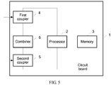
- FIG. 5 is a schematic structural diagram of a base station device disclosed in an embodiment of the present invention.
- the base station device described in FIG. 5 may be a separate device or board, or may be a part newly added to an RRU. This is not limited in this embodiment of the present invention.
- the base station device shown in FIG. 5 may be applied to a scenario in which multiple RRU channel groups are obtained by means of division between a BBU and an RRU and all RRU channels in each RRU channel group are interconnected by using a same bridge.
- the base station device may include a circuit board 1, a processor 2, and a memory 3.
- the processor 2 and the memory 3 are carried on the circuit board 1, and the processor 2 is configured to invoke program code stored in the memory 3, to perform the following operations:
- the base station device shown in FIG. 5 further includes a first coupler 4, a second coupler 5, and a combiner 6 that are carried on the circuit board 1.
- the first coupler 4 and the second coupler 5 are separately electrically connected to the combiner 6, and the combiner 6 is electrically connected to the processor 2.
- a manner in which the processor 2 separately obtains, for the first RRU channel and the second RRU channel that are interconnected in the any RRU channel group, the frequency response difference between the first RRU channel and the separate RRU channel and the frequency response difference between the second RRU channel and the separate RRU channel may be:
- a manner in which the combiner 6 combines the first coupling signal and the second coupling signal to obtain the combined signal is specifically: the combiner 6 processes the first coupling signal by using a first transmission frequency response of the first coupling signal, the combiner 6 processes the second coupling signal by using a second transmission frequency response of the second coupling signal, and the combiner 6 combines the processed first coupling signal and the processed second coupling signal to obtain the combined signal.
- a manner in which the processor 2 collects the combined signal to obtain the first component signal that is of the first calibration signal input from the first RRU channel and that is output from the end, the second component signal that is of the second calibration signal input from the second RRU channel and that is output from the end, and the third component signal that is of the third calibration signal input from the separate RRU channel and that is output from the end is specifically:
- a manner in which the processor 2 compares the first component signal with the first calibration signal to obtain the first frequency response is specifically:
- the foregoing first and second are only used to indicate two different RRU channels, but not to sort the RRU channels.
- the foregoing first transmission frequency response may be used to intuitively evaluate a capability of reproducing the first coupling signal by the system and a noise filtering feature of the system
- the second transmission frequency response may be used to intuitively evaluate a capability of reproducing the second coupling signal by the system and a noise filtering feature of the system
- the third transmission frequency response may be used to intuitively evaluate a capability of reproducing the combined signal by the system and a noise filtering feature of the system.
- the program may be stored in a computer readable storage medium.
- the storage medium includes a read-only memory (Read-Only Memory, ROM), a random access memory (Random Access Memory, RAM), a programmable read-only memory (Programmable Read-only Memory, PROM), an erasable programmable read-only memory (Erasable Programmable Read Only Memory, EPROM), a one-time programmable read-only memory (One-time Programmable Read-Only Memory, OTPROM), an electrically-erasable programmable read-only memory, (Electrically-Erasable Programmable Read-Only Memory, EEPROM), a compact disc read-only memory (Compact Disc Read-Only Memory, CD-ROM), or another optical disk memory, magnetic disk memory, magnetic tape memory, or any other computer readable medium that can be configured to carry or store data
Applications Claiming Priority (1)
| Application Number | Priority Date | Filing Date | Title |
|---|---|---|---|
| PCT/CN2015/098040 WO2017106999A1 (zh) | 2015-12-21 | 2015-12-21 | Rru通道频率响应差异的获取方法及系统、基站设备 |
Publications (2)
| Publication Number | Publication Date |
|---|---|
| EP3382902A1 true EP3382902A1 (de) | 2018-10-03 |
| EP3382902A4 EP3382902A4 (de) | 2018-12-19 |
Family
ID=59088781
Family Applications (1)
| Application Number | Title | Priority Date | Filing Date |
|---|---|---|---|
| EP15910999.0A Ceased EP3382902A4 (de) | 2015-12-21 | 2015-12-21 | Verfahren und system zur erfassung der frequenzreaktionsdifferenz eines kanals einer funkferneinheit (rru) und basisstation |
Country Status (4)
| Country | Link |
|---|---|
| US (1) | US10420172B2 (de) |
| EP (1) | EP3382902A4 (de) |
| CN (1) | CN108432150A (de) |
| WO (1) | WO2017106999A1 (de) |
Family Cites Families (21)
| Publication number | Priority date | Publication date | Assignee | Title |
|---|---|---|---|---|
| KR100487234B1 (ko) * | 2002-07-02 | 2005-05-03 | 삼성전자주식회사 | 이동통신 기지국 시스템 |
| CN102056184B (zh) * | 2009-10-30 | 2014-04-23 | 中兴通讯股份有限公司 | 射频拉远单元链路自适应方法及装置 |
| CN102065531B (zh) * | 2009-11-13 | 2014-06-11 | 中兴通讯股份有限公司 | 一种功率校准的方法及装置 |
| CN102340852B (zh) * | 2010-07-20 | 2015-02-18 | 电信科学技术研究院 | 移动通信系统基站节能方法及装置 |
| CN103001686B (zh) * | 2011-09-16 | 2015-04-29 | 普天信息技术研究院有限公司 | 一种分布式天线系统的上行接收方法 |
| CN103428825A (zh) * | 2012-05-15 | 2013-12-04 | 中国普天信息产业股份有限公司 | 一种射频拉远单元的选择方法 |
| EP2789107B1 (de) * | 2012-08-09 | 2017-02-15 | Axell Wireless Ltd. | Auf digitale kapazität zentriertes verteiltes antennensystem |
| CN103595665B (zh) * | 2012-08-14 | 2017-07-07 | 华为技术有限公司 | 通道校正方法、装置及无线接入系统 |
| CN102891708A (zh) * | 2012-09-17 | 2013-01-23 | 华为技术有限公司 | 收发通道响应的校正方法、装置、系统及bbu |
| CN103905345B (zh) * | 2012-12-27 | 2016-12-28 | 华为技术有限公司 | 通道校正装置、方法及系统 |
| US9432063B2 (en) * | 2013-01-16 | 2016-08-30 | Huawei Technologies Co., Ltd. | Radio frequency signal transceiving and processing method, device, and base station system |
| TWI611159B (zh) * | 2013-06-21 | 2018-01-11 | 吉運動管理公司 | 具有內建式內部投射體饋送機構的壓縮氣槍 |
| CN104378775B (zh) * | 2013-08-16 | 2018-01-05 | 普天信息技术研究院有限公司 | Rru间通道校准的方法 |
| CN106411378B (zh) * | 2013-09-02 | 2019-11-29 | 华为技术有限公司 | 通信设备、基带单元和通信方法 |
| WO2015037820A1 (en) * | 2013-09-13 | 2015-03-19 | Lg Electronics Inc. | Method for setting and updating tracking area in c-ran and apparatus therefor |
| US9716573B2 (en) * | 2014-06-13 | 2017-07-25 | Futurewei Technologies, Inc. | Aggregated touchless wireless fronthaul |
| US9806816B2 (en) * | 2014-10-10 | 2017-10-31 | Futurewei Technologies, Inc. | Re-modulation crosstalk and intensity noise cancellation in wavelength-division multiplexing (WDM) passive optical networks (PONs) |
| US10212611B2 (en) * | 2015-03-16 | 2019-02-19 | Telefonaktiebolaget Lm Ericsson (Publ) | Multipoint transmission and reception in a radio communication network |
| US10771120B2 (en) * | 2015-04-27 | 2020-09-08 | Apple Inc. | Base station front end preprocessing |
| US9793996B2 (en) * | 2015-09-14 | 2017-10-17 | Futurewei Technologies, Inc. | Sub-nyquist sampling for bandwidth- and hardware-efficient mobile fronthaul with MIMO processing |
| US20170188314A1 (en) * | 2015-12-24 | 2017-06-29 | Intel Corporation | Uplink interference management in shared spectrum networks |
-
2015
- 2015-12-21 WO PCT/CN2015/098040 patent/WO2017106999A1/zh active Application Filing
- 2015-12-21 EP EP15910999.0A patent/EP3382902A4/de not_active Ceased
- 2015-12-21 CN CN201580085345.4A patent/CN108432150A/zh active Pending
-
2018
- 2018-06-21 US US16/013,964 patent/US10420172B2/en not_active Expired - Fee Related
Also Published As
| Publication number | Publication date |
|---|---|
| US20180302950A1 (en) | 2018-10-18 |
| CN108432150A (zh) | 2018-08-21 |
| WO2017106999A1 (zh) | 2017-06-29 |
| US10420172B2 (en) | 2019-09-17 |
| EP3382902A4 (de) | 2018-12-19 |
Similar Documents
| Publication | Publication Date | Title |
|---|---|---|
| JP6473207B2 (ja) | 通信方法及びデバイス | |
| CN104753612A (zh) | 一种射频测试方法及系统 | |
| CN103888970A (zh) | 一种测试设备 | |
| CN103905345A (zh) | 通道校正装置、方法及系统 | |
| US10250674B2 (en) | Radio access method, apparatus, and system for implementing mutual transmission and processing of collaborative data between sites | |
| CN108880649B (zh) | 终端的天线配置方法、装置、设备及存储介质 | |
| US20240121038A1 (en) | Carrier configuration method and system for distributed antenna system, processing device, and chip | |
| CN112782567B (zh) | 芯片测试系统、方法、装置、介质及设备 | |
| US10420172B2 (en) | RRU channel frequency response difference obtaining method and system, and base station device | |
| WO2016086588A1 (zh) | 配置rru设备的方法、rru设备、中间设备及计算机存储介质 | |
| US10498388B1 (en) | Electronic device and non-transitory computer readable storage medium | |
| US8837946B2 (en) | Data transmission apparatus and method for use in separate-type base station | |
| CN109460379B (zh) | 一种串口选择的方法及切换装置 | |
| RU2540969C1 (ru) | Способ, базовая станция и система беспроводной связи для взаимной поддержки trx | |
| CN103067053B (zh) | 蓝牙节点处理的方法和装置 | |
| US10651997B2 (en) | Pilot signal configuration method and device | |
| CN109792302B (zh) | 射频系统 | |
| KR20200138738A (ko) | 정보 결정 및 구성 방법, 장치, 컴퓨터 저장 매체 | |
| US20200296610A1 (en) | Method for configuring user equipment measurement parameters and user equipment | |
| US20200274688A1 (en) | Method and apparatus for converting transmitting/receiving frequency signal in fdd communication | |
| CN111342858B (zh) | 信号处理方法及装置 | |
| US9264909B2 (en) | Access point apparatus for configuring next generation wireless communication network and method of operating the access point apparatus | |
| KR20200109357A (ko) | 주파수 포인트 구성 방법, 네트워크 기기, 단말 기기 및 컴퓨터 저장 매체 | |
| CN111404561B (zh) | 基于资源块分推的信号发射方法及相关产品 | |
| US11032820B1 (en) | Receiving wireless local area network (WLAN) packets from co-located access point radios and client device radios |
Legal Events
| Date | Code | Title | Description |
|---|---|---|---|
| PUAI | Public reference made under article 153(3) epc to a published international application that has entered the european phase |
Free format text: ORIGINAL CODE: 0009012 |
|
| 17P | Request for examination filed |
Effective date: 20180628 |
|
| AK | Designated contracting states |
Kind code of ref document: A1 Designated state(s): AL AT BE BG CH CY CZ DE DK EE ES FI FR GB GR HR HU IE IS IT LI LT LU LV MC MK MT NL NO PL PT RO RS SE SI SK SM TR |
|
| AX | Request for extension of the european patent |
Extension state: BA ME |
|
| A4 | Supplementary search report drawn up and despatched |
Effective date: 20181116 |
|
| RIC1 | Information provided on ipc code assigned before grant |
Ipc: H04B 17/12 20150101ALI20181112BHEP Ipc: H04B 7/04 20170101AFI20181112BHEP Ipc: H04B 7/022 20170101ALN20181112BHEP Ipc: H04L 25/02 20060101ALI20181112BHEP |
|
| DAV | Request for validation of the european patent (deleted) | ||
| DAX | Request for extension of the european patent (deleted) | ||
| 17Q | First examination report despatched |
Effective date: 20190813 |
|
| REG | Reference to a national code |
Ref country code: DE Ref legal event code: R003 |
|
| STAA | Information on the status of an ep patent application or granted ep patent |
Free format text: STATUS: THE APPLICATION HAS BEEN REFUSED |
|
| 18R | Application refused |
Effective date: 20200701 |