EP3382890B2 - Pump assembly and controlling method - Google Patents
Pump assembly and controlling method Download PDFInfo
- Publication number
- EP3382890B2 EP3382890B2 EP17164400.8A EP17164400A EP3382890B2 EP 3382890 B2 EP3382890 B2 EP 3382890B2 EP 17164400 A EP17164400 A EP 17164400A EP 3382890 B2 EP3382890 B2 EP 3382890B2
- Authority
- EP
- European Patent Office
- Prior art keywords
- voltage
- input voltage
- power consumption
- converter
- frequency converter
- Prior art date
- Legal status (The legal status is an assumption and is not a legal conclusion. Google has not performed a legal analysis and makes no representation as to the accuracy of the status listed.)
- Active
Links
Images

Classifications
-
- H—ELECTRICITY
- H02—GENERATION; CONVERSION OR DISTRIBUTION OF ELECTRIC POWER
- H02P—CONTROL OR REGULATION OF ELECTRIC MOTORS, ELECTRIC GENERATORS OR DYNAMO-ELECTRIC CONVERTERS; CONTROLLING TRANSFORMERS, REACTORS OR CHOKE COILS
- H02P27/00—Arrangements or methods for the control of AC motors characterised by the kind of supply voltage
- H02P27/04—Arrangements or methods for the control of AC motors characterised by the kind of supply voltage using variable-frequency supply voltage, e.g. inverter or converter supply voltage
- H02P27/047—V/F converter, wherein the voltage is controlled proportionally with the frequency
-
- F—MECHANICAL ENGINEERING; LIGHTING; HEATING; WEAPONS; BLASTING
- F04—POSITIVE - DISPLACEMENT MACHINES FOR LIQUIDS; PUMPS FOR LIQUIDS OR ELASTIC FLUIDS
- F04D—NON-POSITIVE-DISPLACEMENT PUMPS
- F04D13/00—Pumping installations or systems
- F04D13/02—Units comprising pumps and their driving means
- F04D13/06—Units comprising pumps and their driving means the pump being electrically driven
- F04D13/0606—Canned motor pumps
-
- F—MECHANICAL ENGINEERING; LIGHTING; HEATING; WEAPONS; BLASTING
- F04—POSITIVE - DISPLACEMENT MACHINES FOR LIQUIDS; PUMPS FOR LIQUIDS OR ELASTIC FLUIDS
- F04D—NON-POSITIVE-DISPLACEMENT PUMPS
- F04D15/00—Control, e.g. regulation, of pumps, pumping installations or systems
- F04D15/0066—Control, e.g. regulation, of pumps, pumping installations or systems by changing the speed, e.g. of the driving engine
-
- H—ELECTRICITY
- H02—GENERATION; CONVERSION OR DISTRIBUTION OF ELECTRIC POWER
- H02P—CONTROL OR REGULATION OF ELECTRIC MOTORS, ELECTRIC GENERATORS OR DYNAMO-ELECTRIC CONVERTERS; CONTROLLING TRANSFORMERS, REACTORS OR CHOKE COILS
- H02P27/00—Arrangements or methods for the control of AC motors characterised by the kind of supply voltage
- H02P27/04—Arrangements or methods for the control of AC motors characterised by the kind of supply voltage using variable-frequency supply voltage, e.g. inverter or converter supply voltage
- H02P27/06—Arrangements or methods for the control of AC motors characterised by the kind of supply voltage using variable-frequency supply voltage, e.g. inverter or converter supply voltage using dc to ac converters or inverters
- H02P27/08—Arrangements or methods for the control of AC motors characterised by the kind of supply voltage using variable-frequency supply voltage, e.g. inverter or converter supply voltage using dc to ac converters or inverters with pulse width modulation
-
- Y—GENERAL TAGGING OF NEW TECHNOLOGICAL DEVELOPMENTS; GENERAL TAGGING OF CROSS-SECTIONAL TECHNOLOGIES SPANNING OVER SEVERAL SECTIONS OF THE IPC; TECHNICAL SUBJECTS COVERED BY FORMER USPC CROSS-REFERENCE ART COLLECTIONS [XRACs] AND DIGESTS
- Y02—TECHNOLOGIES OR APPLICATIONS FOR MITIGATION OR ADAPTATION AGAINST CLIMATE CHANGE
- Y02B—CLIMATE CHANGE MITIGATION TECHNOLOGIES RELATED TO BUILDINGS, e.g. HOUSING, HOUSE APPLIANCES OR RELATED END-USER APPLICATIONS
- Y02B30/00—Energy efficient heating, ventilation or air conditioning [HVAC]
- Y02B30/70—Efficient control or regulation technologies, e.g. for control of refrigerant flow, motor or heating
Definitions
- the present disclosure relates generally to pump assemblies, in particular to speed controlled wet rotor centrifugal pumps, and a method for controlling an electrical drive motor for driving such a pump.
- Such pumps in the power range of 5W to 3kW are typically used in circulation pumps of house heating systems.
- Speed controlled wet rotor pumps usually comprise a frequency converter configured to drive the motor at a desired speed according to the required pumping power.
- the switching frequency of the frequency converter In order to drive the motor with a pulse width modulated signal having a sinusoidal shape, the switching frequency of the frequency converter must be high, which introduces switching losses in the frequency converter.
- EP 2 133 991 describes a speed controlled pump in which the input voltage to the frequency converter is adapted by a voltage converter to the required output voltage aiming for a maximum modulation index for minimising switching losses in the frequency converter.
- embodiments of the present disclosure provide a pump assembly with further reduced power consumption.
- a pump assembly comprising a pump unit, an electrical drive motor for driving the pump unit, and a control unit for controlling the drive motor.
- the control unit comprises a frequency converter, a voltage converter and a controller, wherein the voltage converter is configured to provide an input voltage U in to the frequency converter, the input voltage being adjustable within a voltage range between a minimum input voltage U min and and a maximum output voltage U max .
- the controller is configured to determine an actual power consumption of at least one of the drive motor, the frequency converter and the voltage converter during operation of the pump unit, and configured to tune the input voltage depending on the determined actual power consumption during operation of the pump unit.
- the controller may be part of the frequency converter or of the voltage converter or a separate component of the control unit.
- the controller may be configured to determine an actual combined power consumption of the drive motor, the frequency converter and the voltage converter, and to tune the input voltage depending on the determined actual combined power consumption.
- the controller may be configured to determine an actual combined power consumption of the drive motor, the frequency converter and the voltage converter, and to tune the input voltage depending on the determined actual combined power consumption.
- the controller may thus be configured to tune the input voltage so that the actual power consumption is minimised.
- a minimum power loss (MPL) algorithm may be applied to find the optimal input voltage for achieving the lowest power consumption of the combined system comprising the drive motor, the frequency converter and the voltage converter.
- the MPL algorithm may increase the input voltage from U 0 to U 1 and compares the power consumption P 0 for U 0 and the power consumption P 1 for U 1 . If the power consumption P 1 for U 1 is smaller than the power consumption P 0 for U 0 , the input voltage may be further increased to U 2 .
- the input voltage may be decreased from U 0 to U' 1 , and then further decreased to U' 2 if the power consumption has reduced by ⁇ P from U 0 to U' 1 .
- the controller is configured to determine a rate of change in actual power consumption in at least one of the drive motor, the frequency converter and the voltage converter during operation of the pump, wherein the controller is configured to tune the input voltage only if the positive rate of change of the actual power consumption is below a defined threshold, or if a parameter relating to the positive rate of change of the actual power consumption is below a defined threshold for that parameter.
- the MPL algorithm may be switched off when the power consumption is rising too quickly and switched on when the power consumption is stable within the defined threshold.
- the controller may be configured to increase the input voltage in a pre-defined manner if the positive rate of change of the actual power consumption is above the threshold. For instance, the input voltage may be increased at a constant rate or steps as long as the positive rate of change of the actual power consumption is above the defined threshold. If the power consumption is rising too quickly, an input voltage achieving a maximum modulation index may be applied.
- the controller may be configured to determine the actual electrical power consumption in pre-defined temporal intervals or in an essentially continuous manner to tune the input voltage accordingly.
- the controller may be configured to determine a power consumption differential ⁇ P between the power consumption when the input voltage is provided and the power consumption when another input voltage was previously provided, wherein tuning the input voltage includes changing the input voltage by a voltage differential ⁇ U, wherein the sign and/or the amount of the voltage differential ⁇ U is dependent on the determined power consumption differential ⁇ P.
- the drive motor may be operable in a field-weakening mode and a non-field-weakening mode, wherein the controller is configured to tune the input voltage within a voltage range between a minimum input voltage U min and a reference voltage U ref in the field weakening mode, and wherein the controller is configured to tune the input voltage within a voltage range between the reference voltage U ref and a maximum input voltage U max in the non-field-weakening mode, wherein U min ⁇ U ref ⁇ U max .
- field-weakening mode shall mean that the stator current partly reduces the total magnetic flux, because it is phase-shifted with respect to the rotor magnetic flux by more than 90°.
- non-field-weakening mode shall mean that a stator current has a phase-shift of 90° or less with respect to the rotor magnetic flux such that no component of the stator current reduces the total magnetic flux.
- the frequency converter and the voltage converter are located on separate circuit boards, preferably separated by a housing wall.
- the pump unit comprises a wet rotor circulation pump for a heating or cooling system.
- a method for controlling an electrical drive motor for driving a pump unit comprising a frequency converter and a voltage converter.
- the method comprises the following steps:
- the step of tuning the input voltage includes tuning the input voltage so that the actual power consumption is minimised.
- the method comprises a further step of determining a rate of change in actual power consumption in at least one of the drive motor, the frequency converter and the voltage converter during operation of the pump, and wherein tuning the input voltage includes the condition that the positive rate of change of the actual power consumption is below a defined threshold.
- the step of tuning the input voltage includes increasing the input voltage in a pre-defined manner if said condition is not fulfilled.
- the step of determining the actual electrical power consumption includes determining the actual electrical power consumption in pre-defined temporal intervals or in an essentially continuous manner for tuning the input voltage accordingly.
- the step of tuning the input voltage includes tuning the input voltage within a voltage range between the minimum input voltage U min and a reference voltage U ref when the drive motor is operated in a field-weakening mode, and wherein tuning the input voltage includes tuning the input voltage within a voltage range between the reference voltage U ref and the maximum input voltage U max when the drive motor is operated in a non-field-weakening mode, wherein U min ⁇ U ref ⁇ U max .
- the method may comprise a step of feeding back the reference voltage U ref from the frequency converter to the voltage converter.
- the voltage converter may then tune the input voltage to the reference voltage in non-field-weakening mode.
- the method may comprise a step of signalling the determined actual total power consumption to the frequency converter.
- the actual total power consumption may be the actual power consumption of the combined system of frequency converter, motor and voltage converter.
- the step of determining the actual total power consumption includes determining an approximate power consumption in the voltage converter based on a look-up table and/or a determined actual power consumption in the frequency converter and/or the input voltage.
- the method may comprise a step of determining a power consumption differential ⁇ P between the power consumption when the input voltage is provided and the power consumption when another input voltage was previously provided, wherein tuning the input voltage includes changing the input voltage by a voltage differential ⁇ U, wherein the sign and/or the amount of the voltage differential ⁇ U is dependent on the determined power consumption differential ⁇ P.
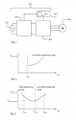
- Fig. 1 shows a pump assembly 1 with a centrifugal pump unit 2, an input port 3 and an output port 5, wherein the input port 3 and an output port 5 are coaxially arranged on a pipe axis A on opposing sides of the pump unit 2.
- the input port 3 and the output port 5 comprise connector flanges 7, 9 for a connection to pipes (not shown).
- the pump unit 2 comprises a rotor axis R essentially perpendicular to the pipe axis A.
- a pump housing 11 of the pump unit 2 is essentially arranged between the input port 3 and the output port 5.
- the pump housing 11 comprises an impeller (not shown) for rotating around the rotor axis R and pumping fluid from the input port 3 to the output port 5.
- the impeller is driven by a motor (not shown) located in a motor housing 13 extending from the pump housing 11 along the rotor axis R to an electronics housing 15.
- the electronics housing 15 comprises a control unit 201 (see Fig. 2 ) for controlling a three-phase synchronous permanent magnet drive motor 203.
- the control circuitry shown in Fig. 2 comprises the control unit 201 for controlling the three-phase synchronous permanent magnet drive motor 203.
- the control unit 201 receives an AC supply voltage 205.
- This AC supply voltage 205 may be a 230V/110V line voltage or it may be a low AC supply voltage, e.g. 60V, provided by an internal or an external power supply unit (not shown).
- the control unit 201 comprises a voltage converter 207 and a frequency converter 209, wherein the voltage converter 207 receives the AC supply voltage 203 and provides a DC input voltage U in to the frequency converter 209.
- the frequency converter 209 provides to each of the three phases of the drive motor 203 a pulse-width modulated AC output voltage U out for driving the motor 203.
- the three phases are phase-shifted by 120° with respect to each other.
- the control unit 201 further comprises a controller 211 controlling switches within the frequency converter 209.
- the controller 211 may be part of the frequency converter 209 or an extra circuitry.
- the controller 211 comprises a minimum power loss module 213 incorporating a minimum power loss (MPL) algorithm.
- the controller 201 is configured to determine an actual power consumption of at least one of the drive motor 203, the frequency converter 209 and the voltage converter 207, preferably an actual total power consumption of a combined system of motor 203, frequency converter 209 and voltage converter 207, during operation of the pump unit 2.
- the input voltage U in provided by the voltage converter 207 is adjustable within a voltage range between U min and U max , wherein the controller 211 is configured to tune the input voltage U in depending on the determined actual power consumption during operation of the pump unit 2.
- the power loss in the combined system of frequency converter 209 and motor 203 rises in non-field-weakening mode from a reference voltage U ref with the input voltage U in .
- the motor 203 may be operated in field-weakening mode.
- the combined system of frequency converter 209 and motor 203 shows a minimum power loss P loss,FC+M,min (see Fig. 4 ) at an input voltage U in that may differ from the reference voltage U ref .
- a minimum power loss P loss,FC+M,min may be in particular lower than the reference voltage U ref such that it may be advantageous to operate in field-weakening mode.
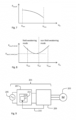
- the voltage converter 207 is in principle more efficient when outputting higher input voltages U in (see Fig.
- the combined system of frequency converter 209, motor 203 and voltage converter 207 shows a resulting minimum power loss P loss,FC+M+VC,min (see Fig. 8 ) at an input voltage U in that may differ from the reference voltage U ref .
- the controller 211 may be configured to tune the input voltage U in so that the power loss of the combined system of frequency converter 209, motor 203 and voltage converter 207 is at its minimum P loss,FC+M+VC,min as shown in Fig. 8 .
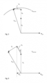
- the vector diagram in a rotating reference frame of Fig. 5 illustrates the phase relation between the main components in non-field weakening mode.
- a magnetic flux ⁇ pm of the permanent magnet is 90° phase-shifted with respect to a phase current I in a stator of the motor 203.
- the resistive voltage drop U R and the back EMF U E are in phase, and the inductive voltage drop U L is 90° phase-shifted with respect to the resistive voltage drop U R .
- the modulation index M is maximal so that the output voltage U out essentially equals a maximum output voltage U out,max illustrated by the circle.
- the input voltage U in may be decreased below the reference voltage U ref , which is possible in field-weakening mode as shown in Fig. 6 .
- the reduced magnetic flux in the motor ⁇ would result in less torque and hydraulic output power of the pump, which may be compensated at part load by a higher phase current I while still consuming less power in total.
- the motor 203 may be operated at full load where the phase current I cannot be increased any further, the field-weakening mode may be less efficient, but that may be rarely the case. Most of the time, the motor 203 may be operated at part load, when a selective operation in field-weakening mode or non-field weakening mode under appropriate tuning of the input voltage U in may be most efficient.
- full load means that the frequency converter is fed with the maximum input power
- part load means that the frequency converter is fed with less than the maximum input power.
- field-weakening mode means that the phase current partly reduces the total magnetic flux, because it is phase-shifted with respect to the rotor magnetic flux by more than 90°.
- the phase current has a phase-shift of 90° or less with respect to the rotor magnetic flux such that no component of the phase current reduces the total magnetic flux.
- position sensors may be used.
- the output voltage U out may be measured to determine whether a motor is running in field-weakening mode or non-field weakening mode.
- the controller 211 is part of the voltage converter 207 receiving the power loss in the frequency converter 209 and in the motor 203 via a feedback loop 215.
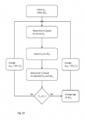
- Fig. 10 further describes the minimum power loss (MPL) algorithm of the minimum power loss (MPL) module 213 of the controller 211.
- MPL minimum power loss
- a first step an initial input voltage U in is provided to the frequency converter 209 by the voltage converter 207.
- the initial input voltage U in is adjustable by an initial voltage differential ⁇ U in so that U in is variably adjustable within a voltage range between U min and U max .
- an actual power consumption P 0 of at least one of the drive motor 203, the frequency converter 209 and the voltage converter 207 during operation of the pump unit 2 is determined and stored.
- the input voltage U in is then varied by the initial voltage differential ⁇ U in , and an actual power consumption P 1 of at least one of the drive motor 203, the frequency converter 209 and the voltage converter 207 during operation of the pump unit 2 is determined.
- the power consumptions P 1 and P 0 are then compared. If P 1 ⁇ P 0 the adjustment decreased the power consumption and the above steps may be repeated starting from the adjusted input voltage U in until P 1 ⁇ P 0 . If P 1 ⁇ P 0 , the sign of ⁇ U in may be changed to adjust U in in the other direction. Thereby, the input voltage U in is tuned depending on the determined actual power consumption during operation of the pump unit 2.
- the MPL algorithm may switch back to the initial voltage differential ⁇ U in once the total minimum power loss of the combined system of frequency converter 209, motor 203 and voltage converter 207 is reached at P loss,FC+M+VC,min .
- the controller 211 is further configured to determine a rate of change in actual power consumption in at least one of the drive motor 203, the frequency converter 209 and the voltage converter 207 during operation of the pump 1, wherein the controller 211 is configured to tune the input voltage U in only if the positive rate of change of the actual power consumption is below a defined threshold, i.e. the frequency converter 209 is operating in a steady power consumption within limits. If the actual power consumption is rising too quickly above limits, the MPL algorithm of Fig. 10 may be suspended until a steady power consumption within limits is reached. The controller 211 may then increase the input voltage U in in a pre-defined manner, e.g. at a constant rate or steps of ⁇ U in . The controller 211 may determine the actual electrical power consumption in pre-defined temporal intervals or in an essentially continuous manner to start tuning the input voltage U in once the power consumption is stable within limits.
Description
- The present disclosure relates generally to pump assemblies, in particular to speed controlled wet rotor centrifugal pumps, and a method for controlling an electrical drive motor for driving such a pump. Such pumps in the power range of 5W to 3kW are typically used in circulation pumps of house heating systems.
- It is a general goal of pump design to reduce the overall power consumption of a pump as much as possible. Speed controlled wet rotor pumps usually comprise a frequency converter configured to drive the motor at a desired speed according to the required pumping power. In order to drive the motor with a pulse width modulated signal having a sinusoidal shape, the switching frequency of the frequency converter must be high, which introduces switching losses in the frequency converter.
-
EP 2 133 991 - In contrast to such known pumps, embodiments of the present disclosure provide a pump assembly with further reduced power consumption.
- In accordance with a first aspect of the present disclosure, a pump assembly is provided comprising a pump unit, an electrical drive motor for driving the pump unit, and a control unit for controlling the drive motor. The control unit comprises a frequency converter, a voltage converter and a controller, wherein the voltage converter is configured to provide an input voltage Uin to the frequency converter, the input voltage being adjustable within a voltage range between a minimum input voltage Umin and and a maximum output voltage Umax. The controller is configured to determine an actual power consumption of at least one of the drive motor, the frequency converter and the voltage converter during operation of the pump unit, and configured to tune the input voltage depending on the determined actual power consumption during operation of the pump unit. The controller may be part of the frequency converter or of the voltage converter or a separate component of the control unit.
- Optionally, the controller may be configured to determine an actual combined power consumption of the drive motor, the frequency converter and the voltage converter, and to tune the input voltage depending on the determined actual combined power consumption. Thereby, not only the switching losses in the frequency converter can be minimised, but in addition the conversion losses in the voltage converter and the power losses in the motor.
- Optionally, the controller may thus be configured to tune the input voltage so that the actual power consumption is minimised. To achieve this, a minimum power loss (MPL) algorithm may be applied to find the optimal input voltage for achieving the lowest power consumption of the combined system comprising the drive motor, the frequency converter and the voltage converter. For instance, the MPL algorithm may increase the input voltage from U0 to U1 and compares the power consumption P0 for U0 and the power consumption P1 for U1. If the power consumption P1 for U1 is smaller than the power consumption P0 for U0, the input voltage may be further increased to U2. If the power consumption P1 for U1 is higher than the power consumption P0 for U0, the input voltage may be decreased from U0 to U'1, and then further decreased to U'2 if the power consumption has reduced by ΔP from U0 to U'1. This process may be iteratively repeated with constant ΔU=U0-U1=U1-U2=... or preferably variable ΔU=f(ΔP) to find the optimal input voltage with the least power consumption as quickly as possible.
- According to the present invention, the controller is configured to determine a rate of change in actual power consumption in at least one of the drive motor, the frequency converter and the voltage converter during operation of the pump, wherein the controller is configured to tune the input voltage only if the positive rate of change of the actual power consumption is below a defined threshold, or if a parameter relating to the positive rate of change of the actual power consumption is below a defined threshold for that parameter. For instance, the MPL algorithm may be switched off when the power consumption is rising too quickly and switched on when the power consumption is stable within the defined threshold.
- Optionally, the controller may be configured to increase the input voltage in a pre-defined manner if the positive rate of change of the actual power consumption is above the threshold. For instance, the input voltage may be increased at a constant rate or steps as long as the positive rate of change of the actual power consumption is above the defined threshold. If the power consumption is rising too quickly, an input voltage achieving a maximum modulation index may be applied. The modulation index M shall be defined herein as the ratio between the effective AC output voltage Uout, i.e. the output phase voltage relative to a neutral potential, of the frequency converter and the maximum effective AC output voltage Uout,max, which is limited by the frequency converter input DC voltage Uin, i.e.

- Optionally, the controller may be configured to determine the actual electrical power consumption in pre-defined temporal intervals or in an essentially continuous manner to tune the input voltage accordingly.
- Optionally, the controller may be configured to determine a power consumption differential ΔP between the power consumption when the input voltage is provided and the power consumption when another input voltage was previously provided, wherein tuning the input voltage includes changing the input voltage by a voltage differential ΔU, wherein the sign and/or the amount of the voltage differential ΔU is dependent on the determined power consumption differential ΔP.
- Optionally, the drive motor may be operable in a field-weakening mode and a non-field-weakening mode, wherein the controller is configured to tune the input voltage within a voltage range between a minimum input voltage Umin and a reference voltage Uref in the field weakening mode, and wherein the controller is configured to tune the input voltage within a voltage range between the reference voltage Uref and a maximum input voltage Umax in the non-field-weakening mode, wherein Umin < Uref < Umax. The reference voltage Uref may be defined herein as the input voltage Uin in non-field-weakening mode for which the modulation index M is maximal, i.e.

- Herein, the term "field-weakening mode" shall mean that the stator current partly reduces the total magnetic flux, because it is phase-shifted with respect to the rotor magnetic flux by more than 90°. The term "non-field-weakening mode" shall mean that a stator current has a phase-shift of 90° or less with respect to the rotor magnetic flux such that no component of the stator current reduces the total magnetic flux.
- Optionally, the frequency converter and the voltage converter are located on separate circuit boards, preferably separated by a housing wall.
- Optionally, the pump unit comprises a wet rotor circulation pump for a heating or cooling system.
- In accordance with a second aspect of the present disclosure, a method for controlling an electrical drive motor for driving a pump unit is provided, wherein a control unit of the electrical drive motor comprises a frequency converter and a voltage converter. The method comprises the following steps:
- providing an input voltage to the frequency converter by the voltage converter, wherein the input voltage is adjustable within a voltage range between Umin and Umax,
- determining an actual power consumption of at least one of the drive motor, the frequency converter and the voltage converter during operation of the pump unit, and
- tuning the input voltage depending on the determined actual power consumption during operation of the pump unit.
- Optionally, the step of tuning the input voltage includes tuning the input voltage so that the actual power consumption is minimised.
- According to the second aspect of the present invention, the method comprises a further step of determining a rate of change in actual power consumption in at least one of the drive motor, the frequency converter and the voltage converter during operation of the pump, and wherein tuning the input voltage includes the condition that the positive rate of change of the actual power consumption is below a defined threshold. Optionally, the step of tuning the input voltage includes increasing the input voltage in a pre-defined manner if said condition is not fulfilled.
- Optionally, the step of determining the actual electrical power consumption includes determining the actual electrical power consumption in pre-defined temporal intervals or in an essentially continuous manner for tuning the input voltage accordingly.
- Optionally, the step of tuning the input voltage includes tuning the input voltage within a voltage range between the minimum input voltage Umin and a reference voltage Uref when the drive motor is operated in a field-weakening mode, and wherein tuning the input voltage includes tuning the input voltage within a voltage range between the reference voltage Uref and the maximum input voltage Umax when the drive motor is operated in a non-field-weakening mode, wherein Umin < Uref < Umax.
- Optionally, the method may comprise a step of feeding back the reference voltage Uref from the frequency converter to the voltage converter. In case of high fluctuations of the power consumption, the voltage converter may then tune the input voltage to the reference voltage in non-field-weakening mode.
- Optionally, the method may comprise a step of signalling the determined actual total power consumption to the frequency converter. The actual total power consumption may be the actual power consumption of the combined system of frequency converter, motor and voltage converter.
- Optionally, the step of determining the actual total power consumption includes determining an approximate power consumption in the voltage converter based on a look-up table and/or a determined actual power consumption in the frequency converter and/or the input voltage.
- Optionally, the method may comprise a step of determining a power consumption differential ΔP between the power consumption when the input voltage is provided and the power consumption when another input voltage was previously provided, wherein tuning the input voltage includes changing the input voltage by a voltage differential ΔU, wherein the sign and/or the amount of the voltage differential ΔU is dependent on the determined power consumption differential ΔP.
- Embodiments of the present disclosure will now be described by way of example with reference to the following figures of which:
-
Fig. 1 shows a perspective view on an example of a pump assembly according to this disclosure; -
Fig. 2 shows a schematic view on a control circuitry of a first example of a pump assembly according to this disclosure; -
Fig. 3 shows a power loss in the combined system of frequency converter and motor operating in non-field-weakening mode as a function of an input voltage to the frequency converter of an example of a pump assembly according to this disclosure; -
Fig. 4 shows a power loss in the combined system of frequency converter and motor operating selectively in either field-weakening mode or non-field-weakening mode as a function of an input voltage to the frequency converter of an example of a pump assembly according to this disclosure; -
Fig. 5 shows a vector diagram for operating an example of a pump assembly disclosed herein in non-field-weakening mode; -
Fig. 6 shows a vector diagram for operating an example of a pump assembly disclosed herein in field-weakening mode; -
Fig. 7 shows a power loss in a voltage converter as a function of an input voltage to the frequency converter of an example of a pump assembly according to this disclosure; -
Fig. 8 shows a power loss in the combined system of frequency converter, motor and voltage converter as a function of an input voltage to the frequency converter of an example of a pump assembly according to this disclosure; -
Fig. 9 shows a schematic view on a control circuitry of a second example of a pump assembly according to this disclosure; and -
Fig. 10 shows a schematic view on a minimum power loss (MPL) algorithm of an example of a pump assembly according to this disclosure. -
Fig. 1 shows apump assembly 1 with acentrifugal pump unit 2, aninput port 3 and anoutput port 5, wherein theinput port 3 and anoutput port 5 are coaxially arranged on a pipe axis A on opposing sides of thepump unit 2. Theinput port 3 and theoutput port 5comprise connector flanges 7, 9 for a connection to pipes (not shown). Thepump unit 2 comprises a rotor axis R essentially perpendicular to the pipe axis A. Apump housing 11 of thepump unit 2 is essentially arranged between theinput port 3 and theoutput port 5. Thepump housing 11 comprises an impeller (not shown) for rotating around the rotor axis R and pumping fluid from theinput port 3 to theoutput port 5. The impeller is driven by a motor (not shown) located in amotor housing 13 extending from thepump housing 11 along the rotor axis R to anelectronics housing 15. Theelectronics housing 15 comprises a control unit 201 (seeFig. 2 ) for controlling a three-phase synchronous permanentmagnet drive motor 203. - The control circuitry shown in
Fig. 2 comprises thecontrol unit 201 for controlling the three-phase synchronous permanentmagnet drive motor 203. Thecontrol unit 201 receives anAC supply voltage 205. ThisAC supply voltage 205 may be a 230V/110V line voltage or it may be a low AC supply voltage, e.g. 60V, provided by an internal or an external power supply unit (not shown). Thecontrol unit 201 comprises avoltage converter 207 and afrequency converter 209, wherein thevoltage converter 207 receives theAC supply voltage 203 and provides a DC input voltage Uin to thefrequency converter 209. Thefrequency converter 209 provides to each of the three phases of the drive motor 203 a pulse-width modulated AC output voltage Uout for driving themotor 203. The three phases are phase-shifted by 120° with respect to each other. - The
control unit 201 further comprises acontroller 211 controlling switches within thefrequency converter 209. Thecontroller 211 may be part of thefrequency converter 209 or an extra circuitry. Thecontroller 211 comprises a minimumpower loss module 213 incorporating a minimum power loss (MPL) algorithm. Thecontroller 201 is configured to determine an actual power consumption of at least one of thedrive motor 203, thefrequency converter 209 and thevoltage converter 207, preferably an actual total power consumption of a combined system ofmotor 203,frequency converter 209 andvoltage converter 207, during operation of thepump unit 2. The input voltage Uin provided by thevoltage converter 207 is adjustable within a voltage range between Umin and Umax, wherein thecontroller 211 is configured to tune the input voltage Uin depending on the determined actual power consumption during operation of thepump unit 2. - As shown in
Fig. 3 , the power loss in the combined system offrequency converter 209 andmotor 203 rises in non-field-weakening mode from a reference voltage Uref with the input voltage Uin. The reference voltage Uref may be the input voltage Uin in non-field-weakening mode for which the modulation index

motor 203 may be operated in field-weakening mode. When selectively operated in field-weakening mode or non-field-weakening mode, the combined system offrequency converter 209 andmotor 203 shows a minimum power loss Ploss,FC+M,min (seeFig. 4 ) at an input voltage Uin that may differ from the reference voltage Uref. For certain load cases, such input voltage Uin resulting in a minimum power loss Ploss,FC+M,min may be in particular lower than the reference voltage Uref such that it may be advantageous to operate in field-weakening mode. Thevoltage converter 207 is in principle more efficient when outputting higher input voltages Uin (seeFig. 7 ), but the combined system offrequency converter 209,motor 203 andvoltage converter 207 shows a resulting minimum power loss Ploss,FC+M+VC,min (seeFig. 8 ) at an input voltage Uin that may differ from the reference voltage Uref. Thus, even including the power loss of the voltage converter, for certain load cases, such input voltage Uin resulting in a minimum power loss Ploss,FC+M,min may be in particular lower than the reference voltage Uref such that it may be advantageous to operate in field-weakening mode. Thecontroller 211 may be configured to tune the input voltage Uin so that the power loss of the combined system offrequency converter 209,motor 203 andvoltage converter 207 is at its minimum Ploss,FC+M+VC,min as shown inFig. 8 . - The vector diagram in a rotating reference frame of
Fig. 5 illustrates the phase relation between the main components in non-field weakening mode. A magnetic flux Ψpm of the permanent magnet is 90° phase-shifted with respect to a phase current I in a stator of themotor 203. An output voltage Uout of thefrequency converter 209 into the stator of themotor 203 results from a resistive voltage drop UR = R · I, a back EMF UE and an inductive voltage drop UL = ω · L · I, where an inductance L includes both a self-inductance and a phase-coupling inductance. The resistive voltage drop UR and the back EMF UE are in phase, and the inductive voltage drop UL is 90° phase-shifted with respect to the resistive voltage drop UR. In the example shown inFig. 5 , the modulation index M is maximal so that the output voltage Uout essentially equals a maximum output voltage Uout,max illustrated by the circle. In non-field weakening mode, thedrive motor 203 of thepump unit 2 disclosed herein may be operated at a maximum modulation index Mmax, wherein thevoltage converter 207 provides an input voltage Uin equal to the reference voltage Uref to thefrequency converter 209, i.e. Uin = Uref. - In order to further reduce the total power consumption, the input voltage Uin may be decreased below the reference voltage Uref, which is possible in field-weakening mode as shown in
Fig. 6 . Thefrequency converter 209 may shift the phase current I by an angle θ, whereby a magnetic flux Ψm = I · L · sinθ is induced by the stator windings weakening the resulting magnetic flux in the motor Ψ = Ψpm + Ψm. The reduced magnetic flux in the motor Ψ would result in less torque and hydraulic output power of the pump, which may be compensated at part load by a higher phase current I while still consuming less power in total. If themotor 203 is operated at full load where the phase current I cannot be increased any further, the field-weakening mode may be less efficient, but that may be rarely the case. Most of the time, themotor 203 may be operated at part load, when a selective operation in field-weakening mode or non-field weakening mode under appropriate tuning of the input voltage Uin may be most efficient. Herein, full load means that the frequency converter is fed with the maximum input power, whereas part load means that the frequency converter is fed with less than the maximum input power. - Thus, field-weakening mode means that the phase current partly reduces the total magnetic flux, because it is phase-shifted with respect to the rotor magnetic flux by more than 90°. In non-field-weakening mode, the phase current has a phase-shift of 90° or less with respect to the rotor magnetic flux such that no component of the phase current reduces the total magnetic flux. In order to measure such a phase shift, position sensors may be used. As an alternative or in addition to using position sensors measuring the phase shift angle θ, the output voltage Uout may be measured to determine whether a motor is running in field-weakening mode or non-field weakening mode. Having determined the magnetic flux Ψ, the resistance R, the inductance L, the motor speed ω and the phase current I, an output voltage Uout,calc may be calculated as

- In the embodiment of
Fig. 9 , thecontroller 211 is part of thevoltage converter 207 receiving the power loss in thefrequency converter 209 and in themotor 203 via afeedback loop 215.Fig. 10 further describes the minimum power loss (MPL) algorithm of the minimum power loss (MPL)module 213 of thecontroller 211. In a first step, an initial input voltage Uin is provided to thefrequency converter 209 by thevoltage converter 207. The initial input voltage Uin is adjustable by an initial voltage differential ΔUin so that Uin is variably adjustable within a voltage range between Umin and Umax. In a second step, an actual power consumption P0 of at least one of thedrive motor 203, thefrequency converter 209 and thevoltage converter 207 during operation of thepump unit 2 is determined and stored. The input voltage Uin is then varied by the initial voltage differential ΔUin, and an actual power consumption P1 of at least one of thedrive motor 203, thefrequency converter 209 and thevoltage converter 207 during operation of thepump unit 2 is determined. The power consumptions P1 and P0 are then compared. If P1 < P0 the adjustment decreased the power consumption and the above steps may be repeated starting from the adjusted input voltage Uin until P1 ≥ P0. If P1 ≥ P0, the sign of ΔUin may be changed to adjust Uin in the other direction. Thereby, the input voltage Uin is tuned depending on the determined actual power consumption during operation of thepump unit 2. - The voltage differential ΔUin may not be constant, but may be a function of the power consumption differential ΔP. So, the smaller the power consumption differential ΔP=|P1-P0| is, the smaller the voltage differential ΔUin may be chosen. The MPL algorithm may switch back to the initial voltage differential ΔUin once the total minimum power loss of the combined system of
frequency converter 209,motor 203 andvoltage converter 207 is reached at Ploss,FC+M+VC,min. - The
controller 211 is further configured to determine a rate of change in actual power consumption in at least one of thedrive motor 203, thefrequency converter 209 and thevoltage converter 207 during operation of thepump 1, wherein thecontroller 211 is configured to tune the input voltage Uin only if the positive rate of change of the actual power consumption is below a defined threshold, i.e. thefrequency converter 209 is operating in a steady power consumption within limits. If the actual power consumption is rising too quickly above limits, the MPL algorithm ofFig. 10 may be suspended until a steady power consumption within limits is reached. Thecontroller 211 may then increase the input voltage Uin in a pre-defined manner, e.g. at a constant rate or steps of ΔUin. Thecontroller 211 may determine the actual electrical power consumption in pre-defined temporal intervals or in an essentially continuous manner to start tuning the input voltage Uin once the power consumption is stable within limits.
Claims (17)
- A pump assembly (1) comprising- a pump unit (2),- an electrical drive motor (203) for driving the pump unit (2), and- a control unit (201) for controlling the drive motor (203),wherein the control unit (201) comprises a frequency converter (209), a voltage converter (207) and a controller (211),wherein the voltage converter (207) is configured to provide an input voltage (Uin) to the frequency converter (209), the input voltage (Uin) being adjustable within a voltage range between a minimum input voltage (Umin) and a maximum input voltage (Umax), characterized in thatthe controller (211) is configured to determine an actual power consumption of at least one of the drive motor (203), the frequency converter (209) and the voltage converter (207) during operation of the pump unit (2), andthe controller (211) is configured to tune the input voltage (Uin) depending on the determined actual power consumption during operation of the pump unit (2), wherein the controller (211) is configured to determine a rate of change in actual power consumption in at least one of the drive motor (203), the frequency converter (209) and the voltage converter (207) during operation of the pump unit (2), wherein the controller (211) is configured to tune the input voltage (Uin) only if the positive rate of change of the actual power consumption is below a defined threshold.
- The pump assembly (1) according to claim 1, wherein the controller (211) is configured to tune the input voltage (Uin) so that the actual power consumption is minimised.
- The pump assembly (1) according to claim 1 or 2, wherein the controller (211) is configured to increase the input voltage (Uin) in a pre-defined manner if the positive rate of change of the actual power consumption is above the threshold.
- The pump assembly (1) according to any of the preceding claims, wherein the controller (211) is configured to determine the actual electrical power consumption in pre-defined temporal intervals or in an essentially continuous manner to tune the input voltage (Uin) accordingly.
- The pump assembly (1) according to any of the preceding claims, wherein the controller (211) is configured to determine a power consumption differential (ΔP) between the power consumption when the input voltage (Uin) is provided and the power consumption when another input voltage (Uin) was previously provided, wherein tuning the input voltage (Uin) includes changing the input voltage by a voltage differential (ΔU), wherein the sign and/or the amount of the voltage differential (ΔU) is dependent on the determined power consumption differential (ΔP).
- The pump assembly (1) according to any of the preceding claims, wherein the drive motor (203) is operable in a field-weakening mode and a non-field-weakening mode, wherein the controller (211) is configured to tune the input voltage (Uin) within a voltage range between the minimum input voltage (Umin) and a reference voltage (Uref) in the field weakening mode, and wherein the controller (211) is configured to tune the input voltage (Uin) within a voltage range between the reference voltage (Uref) and the maximum input voltage (Umax) in the non-field-weakening mode, wherein Umin < Uref < Umax.
- The pump assembly (1) according to any of the preceding claims, wherein the frequency converter (209) and the voltage converter (207) are located on separate circuit boards, preferably separated by a housing wall.
- The pump assembly (1) according to any of the preceding claims, wherein the pump unit (2) comprises a wet rotor circulation pump for a heating or cooling system.
- A method for controlling an electrical drive motor (203) for driving a pump unit (2), wherein a control unit (211) of the electrical drive motor (203) comprises a frequency converter (209) and a voltage converter (207), the method comprising:- providing an input voltage (Uin) to the frequency converter (209) by the voltage converter (207), wherein the input voltage (Uin) is adjustable within a voltage range between a minimum input voltage (Umin) and a maximum input voltage (Umax),
characterized by- determining an actual power consumption of at least one of the drive motor (203), the frequency converter (209) and the voltage converter (207) during operation of the pump unit (2),- determining a rate of change in actual power consumption in at least one of the drive motor (203), the frequency converter (209) and the voltage converter (207) during operation of the pump unit (2), and- tuning the input voltage (Uin) depending on the determined actual power consumption during operation of the pump unit (2), wherein tuning the input voltage (Uin) includes the condition that the positive rate of change of the actual power consumption is below a defined threshold. - The method according to claim 9, wherein tuning the input voltage (Uin) includes tuning the input voltage (Uin) so that the actual power consumption is minimised.
- The method according to claim 9 or 10, wherein tuning the input voltage (Uin) includes increasing the input voltage (Uin) in a pre-defined manner if said condition is not fulfilled.
- The method according to any of the claims 9 to 11, determining the actual electrical power consumption includes determining the actual electrical power consumption in pre-defined temporal intervals or in an essentially continuous manner for tuning the input voltage (Uin) accordingly.
- The method according to any of the claims 9 to 12, wherein tuning the input voltage (Uin) includes tuning the input voltage (Uin) within a voltage range between the minimum input voltage (Umin) and a reference voltage (Uref) when the drive motor (203) is operated in a field-weakening mode, and wherein tuning the input voltage (Uin) includes tuning the input voltage (Uin) within a voltage range between the reference voltage (Uref) and the maximum input voltage (Umax) when the drive motor (203) is operated in a non-field-weakening mode, wherein Umin < Uref < Umax.
- The method according to claim 13, including feeding back the reference voltage (Uref) from the frequency converter (209) to the voltage converter (207).
- The method according to any of the claims 9 to 14, further comprising signalling a determined total actual power consumption of a combined system of frequency converter (209), motor (203) and voltage converter (209) to the frequency converter (209).
- The method according to any of the claims 9 to 15, wherein determining the actual power consumption includes determining a total actual power consumption of a combined system of frequency converter (209), motor (203) and voltage converter (209) using an approximate power consumption in the voltage converter (209) based on a look-up table and/or a determined actual power consumption in the frequency converter (209) and/or the input voltage (Uin).
- The method according to any of the claims 9 to 16, further including determining a power consumption differential (ΔP) between the power consumption when the input voltage (Uin) is provided and the power consumption when another input voltage (Uin) was previously provided, wherein tuning the input voltage (Uin) includes changing the input voltage (Uin) by a voltage differential (ΔU), wherein the sign and/or the amount of the voltage differential (ΔU) is dependent on the determined power consumption differential (ΔP).
Priority Applications (4)
| Application Number | Priority Date | Filing Date | Title |
|---|---|---|---|
| EP17164400.8A EP3382890B2 (en) | 2017-03-31 | 2017-03-31 | Pump assembly and controlling method |
| US15/938,302 US10361649B2 (en) | 2017-03-31 | 2018-03-28 | Pump assembly and controlling method |
| RU2018111032A RU2696723C1 (en) | 2017-03-31 | 2018-03-28 | Pump unit and control method |
| CN201810282017.9A CN108696227B (en) | 2017-03-31 | 2018-04-02 | Pump assembly and control method |
Applications Claiming Priority (1)
| Application Number | Priority Date | Filing Date | Title |
|---|---|---|---|
| EP17164400.8A EP3382890B2 (en) | 2017-03-31 | 2017-03-31 | Pump assembly and controlling method |
Publications (3)
| Publication Number | Publication Date |
|---|---|
| EP3382890A1 EP3382890A1 (en) | 2018-10-03 |
| EP3382890B1 EP3382890B1 (en) | 2020-07-22 |
| EP3382890B2 true EP3382890B2 (en) | 2023-05-24 |
Family
ID=58489521
Family Applications (1)
| Application Number | Title | Priority Date | Filing Date |
|---|---|---|---|
| EP17164400.8A Active EP3382890B2 (en) | 2017-03-31 | 2017-03-31 | Pump assembly and controlling method |
Country Status (4)
| Country | Link |
|---|---|
| US (1) | US10361649B2 (en) |
| EP (1) | EP3382890B2 (en) |
| CN (1) | CN108696227B (en) |
| RU (1) | RU2696723C1 (en) |
Families Citing this family (1)
| Publication number | Priority date | Publication date | Assignee | Title |
|---|---|---|---|---|
| US11286925B2 (en) * | 2019-04-23 | 2022-03-29 | Peopleflo Manufacturing, Inc. | Electronic apparatus and method for optimizing the use of motor-driven equipment in a control loop system |
Family Cites Families (16)
| Publication number | Priority date | Publication date | Assignee | Title |
|---|---|---|---|---|
| US4249120A (en) | 1979-07-26 | 1981-02-03 | Mcgraw-Edison Co. | Variable speed induction motor control system |
| US4473338A (en) * | 1980-09-15 | 1984-09-25 | Garmong Victor H | Controlled well pump and method of analyzing well production |
| US5092302A (en) * | 1990-12-26 | 1992-03-03 | Ford Motor Company | Fuel pump speed control by dc-dc converter |
| US5318409A (en) * | 1993-03-23 | 1994-06-07 | Westinghouse Electric Corp. | Rod pump flow rate determination from motor power |
| US6045333A (en) * | 1997-12-01 | 2000-04-04 | Camco International, Inc. | Method and apparatus for controlling a submergible pumping system |
| RU2157468C1 (en) | 1999-02-08 | 2000-10-10 | Самарская государственная архитектурно-строительная академия | Method for regulation of usage of rotary pump |
| US6414455B1 (en) * | 2000-04-03 | 2002-07-02 | Alvin J. Watson | System and method for variable drive pump control |
| EP1286458A1 (en) | 2001-08-22 | 2003-02-26 | Pumpenfabrik Ernst Vogel Gesellschaft m.b.H. | Method and device to control a rotary power unit |
| US7221121B2 (en) * | 2001-11-23 | 2007-05-22 | Danfoss Drives A/S | Frequency converter for different mains voltages |
| EP2133991B2 (en) | 2008-06-09 | 2021-08-25 | Grundfos Management A/S | Centrifugal pump assembly |
| TWI495256B (en) * | 2012-06-26 | 2015-08-01 | Asia Pacific Fuel Cell Tech | Motor power control system |
| EP2733358A1 (en) * | 2012-11-15 | 2014-05-21 | ABB Oy | Method for approximating the static head downstream of a pump |
| EP2750266B1 (en) | 2012-12-27 | 2021-10-20 | Grundfos Holding A/S | Pump power unit |
| EP2905888A1 (en) * | 2014-02-05 | 2015-08-12 | Grundfos Holding A/S | Inverter |
| JP6345135B2 (en) * | 2015-02-25 | 2018-06-20 | 東芝キヤリア株式会社 | Motor drive device |
| CN106026851A (en) * | 2016-07-13 | 2016-10-12 | 广州东芝白云菱机电力电子有限公司 | Motor inverter based on chopper for power compensation |
-
2017
- 2017-03-31 EP EP17164400.8A patent/EP3382890B2/en active Active
-
2018
- 2018-03-28 RU RU2018111032A patent/RU2696723C1/en active
- 2018-03-28 US US15/938,302 patent/US10361649B2/en active Active
- 2018-04-02 CN CN201810282017.9A patent/CN108696227B/en active Active
Also Published As
| Publication number | Publication date |
|---|---|
| CN108696227A (en) | 2018-10-23 |
| EP3382890A1 (en) | 2018-10-03 |
| EP3382890B1 (en) | 2020-07-22 |
| US10361649B2 (en) | 2019-07-23 |
| RU2696723C1 (en) | 2019-08-05 |
| US20180287542A1 (en) | 2018-10-04 |
| CN108696227B (en) | 2021-10-08 |
Similar Documents
| Publication | Publication Date | Title |
|---|---|---|
| CN101884164B (en) | Ac motor controller | |
| US6979967B2 (en) | Efficiency optimization control for permanent magnet motor drive | |
| JP4609078B2 (en) | Electric motor drive device and air conditioner using the same | |
| EP2151918A1 (en) | Operating a synchronous motor having a permanent magnet rotor | |
| US20040042904A1 (en) | Apparatus and method for controlling output of linear compressor | |
| US20090309525A1 (en) | Drive for motor | |
| EP3482491B1 (en) | Closed loop flux weakening for permanent magent synchronous motors | |
| US10756664B2 (en) | System for applying maximum driving efficiency point of load | |
| KR20070074623A (en) | Vsd control | |
| JP3806539B2 (en) | Control method of permanent magnet type synchronous motor | |
| EP3382890B2 (en) | Pump assembly and controlling method | |
| JP2015043682A (en) | Drive unit | |
| JP2006149097A (en) | Motor controller | |
| JP2017158280A (en) | Electric motor driving system | |
| JP4791319B2 (en) | Inverter device, compressor drive device and refrigeration / air-conditioning device | |
| US11005394B2 (en) | Control system and control method | |
| JP2018042315A (en) | Inverter controller | |
| WO2015011945A1 (en) | Drive device | |
| EP3382888B1 (en) | Pump assembly and controlling method | |
| JP2005229736A (en) | Motor drive unit and air conditioner using the same | |
| KR20040076789A (en) | Motor Control Apparatus and Motor Control Method | |
| CN112567620B (en) | Inverter device | |
| JP2006158141A (en) | Motor driving device and air-conditioner | |
| JP2004266904A (en) | Operation controller for motor | |
| KR101924400B1 (en) | Apparatus and method for controlling inverter |
Legal Events
| Date | Code | Title | Description |
|---|---|---|---|
| PUAI | Public reference made under article 153(3) epc to a published international application that has entered the european phase |
Free format text: ORIGINAL CODE: 0009012 |
|
| STAA | Information on the status of an ep patent application or granted ep patent |
Free format text: STATUS: THE APPLICATION HAS BEEN PUBLISHED |
|
| AK | Designated contracting states |
Kind code of ref document: A1 Designated state(s): AL AT BE BG CH CY CZ DE DK EE ES FI FR GB GR HR HU IE IS IT LI LT LU LV MC MK MT NL NO PL PT RO RS SE SI SK SM TR |
|
| AX | Request for extension of the european patent |
Extension state: BA ME |
|
| STAA | Information on the status of an ep patent application or granted ep patent |
Free format text: STATUS: REQUEST FOR EXAMINATION WAS MADE |
|
| 17P | Request for examination filed |
Effective date: 20190129 |
|
| RBV | Designated contracting states (corrected) |
Designated state(s): AL AT BE BG CH CY CZ DE DK EE ES FI FR GB GR HR HU IE IS IT LI LT LU LV MC MK MT NL NO PL PT RO RS SE SI SK SM TR |
|
| GRAP | Despatch of communication of intention to grant a patent |
Free format text: ORIGINAL CODE: EPIDOSNIGR1 |
|
| STAA | Information on the status of an ep patent application or granted ep patent |
Free format text: STATUS: GRANT OF PATENT IS INTENDED |
|
| INTG | Intention to grant announced |
Effective date: 20200218 |
|
| GRAS | Grant fee paid |
Free format text: ORIGINAL CODE: EPIDOSNIGR3 |
|
| GRAA | (expected) grant |
Free format text: ORIGINAL CODE: 0009210 |
|
| STAA | Information on the status of an ep patent application or granted ep patent |
Free format text: STATUS: THE PATENT HAS BEEN GRANTED |
|
| AK | Designated contracting states |
Kind code of ref document: B1 Designated state(s): AL AT BE BG CH CY CZ DE DK EE ES FI FR GB GR HR HU IE IS IT LI LT LU LV MC MK MT NL NO PL PT RO RS SE SI SK SM TR |
|
| REG | Reference to a national code |
Ref country code: GB Ref legal event code: FG4D |
|
| REG | Reference to a national code |
Ref country code: CH Ref legal event code: EP |
|
| REG | Reference to a national code |
Ref country code: DE Ref legal event code: R096 Ref document number: 602017020037 Country of ref document: DE |
|
| REG | Reference to a national code |
Ref country code: AT Ref legal event code: REF Ref document number: 1294341 Country of ref document: AT Kind code of ref document: T Effective date: 20200815 |
|
| REG | Reference to a national code |
Ref country code: IE Ref legal event code: FG4D |
|
| REG | Reference to a national code |
Ref country code: LT Ref legal event code: MG4D |
|
| REG | Reference to a national code |
Ref country code: AT Ref legal event code: MK05 Ref document number: 1294341 Country of ref document: AT Kind code of ref document: T Effective date: 20200722 |
|
| PG25 | Lapsed in a contracting state [announced via postgrant information from national office to epo] |
Ref country code: FI Free format text: LAPSE BECAUSE OF FAILURE TO SUBMIT A TRANSLATION OF THE DESCRIPTION OR TO PAY THE FEE WITHIN THE PRESCRIBED TIME-LIMIT Effective date: 20200722 Ref country code: LT Free format text: LAPSE BECAUSE OF FAILURE TO SUBMIT A TRANSLATION OF THE DESCRIPTION OR TO PAY THE FEE WITHIN THE PRESCRIBED TIME-LIMIT Effective date: 20200722 Ref country code: PT Free format text: LAPSE BECAUSE OF FAILURE TO SUBMIT A TRANSLATION OF THE DESCRIPTION OR TO PAY THE FEE WITHIN THE PRESCRIBED TIME-LIMIT Effective date: 20201123 Ref country code: BG Free format text: LAPSE BECAUSE OF FAILURE TO SUBMIT A TRANSLATION OF THE DESCRIPTION OR TO PAY THE FEE WITHIN THE PRESCRIBED TIME-LIMIT Effective date: 20201022 Ref country code: AT Free format text: LAPSE BECAUSE OF FAILURE TO SUBMIT A TRANSLATION OF THE DESCRIPTION OR TO PAY THE FEE WITHIN THE PRESCRIBED TIME-LIMIT Effective date: 20200722 Ref country code: ES Free format text: LAPSE BECAUSE OF FAILURE TO SUBMIT A TRANSLATION OF THE DESCRIPTION OR TO PAY THE FEE WITHIN THE PRESCRIBED TIME-LIMIT Effective date: 20200722 Ref country code: NO Free format text: LAPSE BECAUSE OF FAILURE TO SUBMIT A TRANSLATION OF THE DESCRIPTION OR TO PAY THE FEE WITHIN THE PRESCRIBED TIME-LIMIT Effective date: 20201022 Ref country code: GR Free format text: LAPSE BECAUSE OF FAILURE TO SUBMIT A TRANSLATION OF THE DESCRIPTION OR TO PAY THE FEE WITHIN THE PRESCRIBED TIME-LIMIT Effective date: 20201023 Ref country code: HR Free format text: LAPSE BECAUSE OF FAILURE TO SUBMIT A TRANSLATION OF THE DESCRIPTION OR TO PAY THE FEE WITHIN THE PRESCRIBED TIME-LIMIT Effective date: 20200722 Ref country code: SE Free format text: LAPSE BECAUSE OF FAILURE TO SUBMIT A TRANSLATION OF THE DESCRIPTION OR TO PAY THE FEE WITHIN THE PRESCRIBED TIME-LIMIT Effective date: 20200722 |
|
| PG25 | Lapsed in a contracting state [announced via postgrant information from national office to epo] |
Ref country code: RS Free format text: LAPSE BECAUSE OF FAILURE TO SUBMIT A TRANSLATION OF THE DESCRIPTION OR TO PAY THE FEE WITHIN THE PRESCRIBED TIME-LIMIT Effective date: 20200722 Ref country code: PL Free format text: LAPSE BECAUSE OF FAILURE TO SUBMIT A TRANSLATION OF THE DESCRIPTION OR TO PAY THE FEE WITHIN THE PRESCRIBED TIME-LIMIT Effective date: 20200722 Ref country code: LV Free format text: LAPSE BECAUSE OF FAILURE TO SUBMIT A TRANSLATION OF THE DESCRIPTION OR TO PAY THE FEE WITHIN THE PRESCRIBED TIME-LIMIT Effective date: 20200722 Ref country code: IS Free format text: LAPSE BECAUSE OF FAILURE TO SUBMIT A TRANSLATION OF THE DESCRIPTION OR TO PAY THE FEE WITHIN THE PRESCRIBED TIME-LIMIT Effective date: 20201122 |
|
| PG25 | Lapsed in a contracting state [announced via postgrant information from national office to epo] |
Ref country code: NL Free format text: LAPSE BECAUSE OF FAILURE TO SUBMIT A TRANSLATION OF THE DESCRIPTION OR TO PAY THE FEE WITHIN THE PRESCRIBED TIME-LIMIT Effective date: 20200722 |
|
| REG | Reference to a national code |
Ref country code: DE Ref legal event code: R026 Ref document number: 602017020037 Country of ref document: DE |
|
| PG25 | Lapsed in a contracting state [announced via postgrant information from national office to epo] |
Ref country code: EE Free format text: LAPSE BECAUSE OF FAILURE TO SUBMIT A TRANSLATION OF THE DESCRIPTION OR TO PAY THE FEE WITHIN THE PRESCRIBED TIME-LIMIT Effective date: 20200722 Ref country code: SM Free format text: LAPSE BECAUSE OF FAILURE TO SUBMIT A TRANSLATION OF THE DESCRIPTION OR TO PAY THE FEE WITHIN THE PRESCRIBED TIME-LIMIT Effective date: 20200722 Ref country code: RO Free format text: LAPSE BECAUSE OF FAILURE TO SUBMIT A TRANSLATION OF THE DESCRIPTION OR TO PAY THE FEE WITHIN THE PRESCRIBED TIME-LIMIT Effective date: 20200722 Ref country code: CZ Free format text: LAPSE BECAUSE OF FAILURE TO SUBMIT A TRANSLATION OF THE DESCRIPTION OR TO PAY THE FEE WITHIN THE PRESCRIBED TIME-LIMIT Effective date: 20200722 Ref country code: DK Free format text: LAPSE BECAUSE OF FAILURE TO SUBMIT A TRANSLATION OF THE DESCRIPTION OR TO PAY THE FEE WITHIN THE PRESCRIBED TIME-LIMIT Effective date: 20200722 |
|
| PLBI | Opposition filed |
Free format text: ORIGINAL CODE: 0009260 |
|
| PLAX | Notice of opposition and request to file observation + time limit sent |
Free format text: ORIGINAL CODE: EPIDOSNOBS2 |
|
| PG25 | Lapsed in a contracting state [announced via postgrant information from national office to epo] |
Ref country code: AL Free format text: LAPSE BECAUSE OF FAILURE TO SUBMIT A TRANSLATION OF THE DESCRIPTION OR TO PAY THE FEE WITHIN THE PRESCRIBED TIME-LIMIT Effective date: 20200722 |
|
| 26 | Opposition filed |
Opponent name: KSB SE & CO. KGAA Effective date: 20210422 Opponent name: WILO SE Effective date: 20210422 |
|
| PG25 | Lapsed in a contracting state [announced via postgrant information from national office to epo] |
Ref country code: SK Free format text: LAPSE BECAUSE OF FAILURE TO SUBMIT A TRANSLATION OF THE DESCRIPTION OR TO PAY THE FEE WITHIN THE PRESCRIBED TIME-LIMIT Effective date: 20200722 |
|
| PG25 | Lapsed in a contracting state [announced via postgrant information from national office to epo] |
Ref country code: SI Free format text: LAPSE BECAUSE OF FAILURE TO SUBMIT A TRANSLATION OF THE DESCRIPTION OR TO PAY THE FEE WITHIN THE PRESCRIBED TIME-LIMIT Effective date: 20200722 |
|
| PLBB | Reply of patent proprietor to notice(s) of opposition received |
Free format text: ORIGINAL CODE: EPIDOSNOBS3 |
|
| REG | Reference to a national code |
Ref country code: NL Ref legal event code: MP Effective date: 20200722 |
|
| PG25 | Lapsed in a contracting state [announced via postgrant information from national office to epo] |
Ref country code: MC Free format text: LAPSE BECAUSE OF FAILURE TO SUBMIT A TRANSLATION OF THE DESCRIPTION OR TO PAY THE FEE WITHIN THE PRESCRIBED TIME-LIMIT Effective date: 20200722 |
|
| REG | Reference to a national code |
Ref country code: CH Ref legal event code: PL |
|
| REG | Reference to a national code |
Ref country code: BE Ref legal event code: MM Effective date: 20210331 |
|
| PG25 | Lapsed in a contracting state [announced via postgrant information from national office to epo] |
Ref country code: LI Free format text: LAPSE BECAUSE OF NON-PAYMENT OF DUE FEES Effective date: 20210331 Ref country code: LU Free format text: LAPSE BECAUSE OF NON-PAYMENT OF DUE FEES Effective date: 20210331 Ref country code: CH Free format text: LAPSE BECAUSE OF NON-PAYMENT OF DUE FEES Effective date: 20210331 Ref country code: IE Free format text: LAPSE BECAUSE OF NON-PAYMENT OF DUE FEES Effective date: 20210331 |
|
| PG25 | Lapsed in a contracting state [announced via postgrant information from national office to epo] |
Ref country code: BE Free format text: LAPSE BECAUSE OF NON-PAYMENT OF DUE FEES Effective date: 20210331 |
|
| REG | Reference to a national code |
Ref country code: DE Ref legal event code: R082 Ref document number: 602017020037 Country of ref document: DE |
|
| PUAH | Patent maintained in amended form |
Free format text: ORIGINAL CODE: 0009272 |
|
| STAA | Information on the status of an ep patent application or granted ep patent |
Free format text: STATUS: PATENT MAINTAINED AS AMENDED |
|
| PGFP | Annual fee paid to national office [announced via postgrant information from national office to epo] |
Ref country code: FR Payment date: 20230327 Year of fee payment: 7 |
|
| 27A | Patent maintained in amended form |
Effective date: 20230524 |
|
| AK | Designated contracting states |
Kind code of ref document: B2 Designated state(s): AL AT BE BG CH CY CZ DE DK EE ES FI FR GB GR HR HU IE IS IT LI LT LU LV MC MK MT NL NO PL PT RO RS SE SI SK SM TR |
|
| REG | Reference to a national code |
Ref country code: DE Ref legal event code: R102 Ref document number: 602017020037 Country of ref document: DE |
|
| PGFP | Annual fee paid to national office [announced via postgrant information from national office to epo] |
Ref country code: IT Payment date: 20230328 Year of fee payment: 7 Ref country code: GB Payment date: 20230322 Year of fee payment: 7 Ref country code: DE Payment date: 20230321 Year of fee payment: 7 |
|
| PG25 | Lapsed in a contracting state [announced via postgrant information from national office to epo] |
Ref country code: CY Free format text: LAPSE BECAUSE OF FAILURE TO SUBMIT A TRANSLATION OF THE DESCRIPTION OR TO PAY THE FEE WITHIN THE PRESCRIBED TIME-LIMIT Effective date: 20200722 |
|
| PG25 | Lapsed in a contracting state [announced via postgrant information from national office to epo] |
Ref country code: HU Free format text: LAPSE BECAUSE OF FAILURE TO SUBMIT A TRANSLATION OF THE DESCRIPTION OR TO PAY THE FEE WITHIN THE PRESCRIBED TIME-LIMIT; INVALID AB INITIO Effective date: 20170331 |