EP3382487B1 - Work vehicle and automatic stop system of work vehicle - Google Patents
Work vehicle and automatic stop system of work vehicle Download PDFInfo
- Publication number
- EP3382487B1 EP3382487B1 EP18154336.4A EP18154336A EP3382487B1 EP 3382487 B1 EP3382487 B1 EP 3382487B1 EP 18154336 A EP18154336 A EP 18154336A EP 3382487 B1 EP3382487 B1 EP 3382487B1
- Authority
- EP
- European Patent Office
- Prior art keywords
- communication
- tractor
- communication system
- vehicle body
- travel
- Prior art date
- Legal status (The legal status is an assumption and is not a legal conclusion. Google has not performed a legal analysis and makes no representation as to the accuracy of the status listed.)
- Active
Links
Images


Classifications
-
- G—PHYSICS
- G05—CONTROLLING; REGULATING
- G05D—SYSTEMS FOR CONTROLLING OR REGULATING NON-ELECTRIC VARIABLES
- G05D1/00—Control of position, course, altitude or attitude of land, water, air or space vehicles, e.g. using automatic pilots
- G05D1/0055—Control of position, course, altitude or attitude of land, water, air or space vehicles, e.g. using automatic pilots with safety arrangements
-
- E—FIXED CONSTRUCTIONS
- E02—HYDRAULIC ENGINEERING; FOUNDATIONS; SOIL SHIFTING
- E02F—DREDGING; SOIL-SHIFTING
- E02F9/00—Component parts of dredgers or soil-shifting machines, not restricted to one of the kinds covered by groups E02F3/00 - E02F7/00
- E02F9/20—Drives; Control devices
- E02F9/2025—Particular purposes of control systems not otherwise provided for
- E02F9/205—Remotely operated machines, e.g. unmanned vehicles
-
- B—PERFORMING OPERATIONS; TRANSPORTING
- B60—VEHICLES IN GENERAL
- B60T—VEHICLE BRAKE CONTROL SYSTEMS OR PARTS THEREOF; BRAKE CONTROL SYSTEMS OR PARTS THEREOF, IN GENERAL; ARRANGEMENT OF BRAKING ELEMENTS ON VEHICLES IN GENERAL; PORTABLE DEVICES FOR PREVENTING UNWANTED MOVEMENT OF VEHICLES; VEHICLE MODIFICATIONS TO FACILITATE COOLING OF BRAKES
- B60T7/00—Brake-action initiating means
- B60T7/12—Brake-action initiating means for automatic initiation; for initiation not subject to will of driver or passenger
- B60T7/22—Brake-action initiating means for automatic initiation; for initiation not subject to will of driver or passenger initiated by contact of vehicle, e.g. bumper, with an external object, e.g. another vehicle, or by means of contactless obstacle detectors mounted on the vehicle
-
- G—PHYSICS
- G05—CONTROLLING; REGULATING
- G05D—SYSTEMS FOR CONTROLLING OR REGULATING NON-ELECTRIC VARIABLES
- G05D1/00—Control of position, course, altitude or attitude of land, water, air or space vehicles, e.g. using automatic pilots
- G05D1/0011—Control of position, course, altitude or attitude of land, water, air or space vehicles, e.g. using automatic pilots associated with a remote control arrangement
-
- G—PHYSICS
- G05—CONTROLLING; REGULATING
- G05D—SYSTEMS FOR CONTROLLING OR REGULATING NON-ELECTRIC VARIABLES
- G05D1/00—Control of position, course, altitude or attitude of land, water, air or space vehicles, e.g. using automatic pilots
- G05D1/0011—Control of position, course, altitude or attitude of land, water, air or space vehicles, e.g. using automatic pilots associated with a remote control arrangement
- G05D1/0022—Control of position, course, altitude or attitude of land, water, air or space vehicles, e.g. using automatic pilots associated with a remote control arrangement characterised by the communication link
-
- G—PHYSICS
- G08—SIGNALLING
- G08G—TRAFFIC CONTROL SYSTEMS
- G08G1/00—Traffic control systems for road vehicles
- G08G1/16—Anti-collision systems
- G08G1/166—Anti-collision systems for active traffic, e.g. moving vehicles, pedestrians, bikes
Definitions
- the embodiment discussed herein is directed to a work vehicle and an automatic stop system of the work vehicle.
- a sensor for detecting an obstacle is provided in a work vehicle, which is able not only to travel automatically but also to travel by a remote operation by using a transmitter, and the vehicle automatically stops when the sensor detects an obstacle.
- Literature related to the conventional technique is Japanese Laid-open Patent Publication No. 62-297909 , for example.
- the detection is to be performed in all directions, and thus a plurality of sensors is to be provided in the work vehicle. Moreover, there exists a fear for failing to detect an obstacle in some cases.
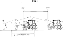
- FIG. 1 is a diagram illustrating an automatic stop system of the tractor 1 according to the embodiment.
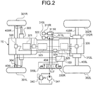
- FIG. 2 is a diagram illustrating the tractor 1.
- FIG. 3 is a diagram illustrating a power transmitting path of the tractor 1.
- FIG. 4 is a control block diagram mainly illustrating a vehicle controller 100 in the automatic stop system of the tractor 1.
- the automatic stop system of the tractor 1 includes the tractor 1, a communication unit 110 that is provided in the tractor 1, a portable communication terminal 3 that is carried by a first worker M1, and the vehicle controller 100 that functions as a travel stopping unit.
- the communication unit 110 receives a signal from the portable communication terminal 3, the travel stopping unit is able to stop a travel of the tractor 1 even when the tractor 1 is unmanned.
- the system includes a remote controller 2 that is able to perform a remote operation on the tractor 1.
- a second worker M2 is assumed to carry the remote controller 2.
- the workers may be collectively referred to as "workers M".
- the communication unit 110 of this automatic stop system includes a first communication unit 111, a second communication unit 112, and a third communication unit 113.
- the communication unit 110 is able to communicate with the portable communication terminal 3 by using a first communication system R1 via the first communication unit 111 and by using a second communication system R2 via the second communication unit 112.
- the communication unit 110 is able to communicate with the remote controller 2 by using a third communication system R3 via the third communication unit 113.
- the portable communication terminal 3 is able to communicate with the tractor 1 by using a plurality of communication systems R including the first communication system R1 and the second communication system R2 (see FIG. 4 ).
- the first communication system R1 is able to transmit a stop signal.
- a communication area of the second communication system R2 is smaller than that of the first communication system R1, and is able to receive a detection signal indicating that the portable communication terminal 3 exists in a predetermined area.
- a communication area of the third communication system R3, which connects the remote controller 2 and the communication unit 110, is defined to be larger than at least of that of the second communication system R2, and the second worker M2 is able to perform a remote operation by using the remote controller 2 with respect to a travel, a work, etc. of the tractor 1.
- a short-distance radio communication standard is employed for the second communication system R2 among the plurality of communication systems R that connect the tractor 1 and the portable communication terminal 3.
- the vehicle controller 100 of the tractor 1 When receiving a second signal indicating that the portable communication terminal 3 exists in an automatic stop area S during travelling of a travelling vehicle body 10, the vehicle controller 100 of the tractor 1 is configured to cause the travelling vehicle body 10 to stop travelling. It is needless to say that the length of the automatic stop area S is approximate to that of a communicable area of the second communication system R2.
- a wireless communication standard which has a larger communication area than that of the short-distance radio communication standard employed for the second communication system R2, is employed for the first communication system R1.
- a remote operation is able to be performed on the tractor 1 with respect to a travel or a travel stop by using a signal transmitted from the remote controller 2, moreover, the travel stop is performed by a signal from not only the remote controller 2 but also the portable communication terminal 3.
- the vehicle controller 100 performs an urgent stop when the communication unit 110 receives the first signal or the second signal.
- the tractor 1 advances to reach the automatic stop area S.
- the unmanned tractor 1 is automatically stopped.
- the unmanned tractor 1 is able to be automatically stopped when receiving the second signal sent from the portable communication terminal 3.
- the travel stopping system of the tractor 1 is able to detect the fact that the portable communication terminal 3 exists in the near distance, in addition to a signal transmitted from the remote controller 2 that is for stopping the tractor 1 by using a remote operation. Therefore, when the tractor 1 is caused to automatically travel in a field etc., a risk in the neighborhood of the travelling vehicle body 10 is able to be previously detected by the tractor 1 side so as to cause the tractor 1 to automatically stop, so that it is possible to contribute to improvement in the safety of the automatically-travelling tractor 1.
- the tractor 1 including the travelling vehicle body 10 further includes the vehicle controller 100 and the communication unit 110 as illustrated in FIG. 4 .
- the travelling vehicle body 10 includes a steering handle (not illustrated), an operation pedal (not illustrated), and a maneuvering part provided with various instruments, and is configured so that a rear part of the travelling vehicle body 10 is able to be connected with a work part including a working machine or a working device (not illustrated).
- a Differential Global Positioning System (DGPS) antenna 6 (see FIG. 1 ), which receives radio waves transmitted from a plurality of navigation satellites, is placed on a ceiling part of the travelling vehicle body 10.
- DGPS Differential Global Positioning System
- the vehicle controller 100 is constituted of a computer, and is able to control, by using electronic control, various units of the tractor 1 such as an automatic travelling unit 160.
- the communication unit 110 is able to communicate with the remote controller 2 and the portable communication terminal 3 in a wireless manner.
- the tractor 1 includes various mechanisms such as power transmitting mechanisms illustrated in FIGS. 2 and 3 .
- the tractor 1 includes, on the respective left and right sides of the travelling vehicle body 10, (i) front wheels 301L and 301R that are attached to left and right front axles 406L and 406R and (ii) left and right rear wheels 302L and 302R that are attached to left and right rear axles 405L and 405R.
- the left side is indicated by the reference symbol represented with "L”
- the right side is indicated by the reference symbol represented with "R”
- the reference symbol is to be described as, for example, a front wheel 301, a rear wheel 302, etc.
- the tractor 1 On a front part of the travelling vehicle body 10, an engine 321 as a power source is mounted, and the power is transmitted from this engine 321 to the front wheels 301 and the rear wheels 302 via the power transmitting mechanism.
- the tractor 1 includes a 4-wheel-drive (4WD) clutch 324, and is configured to be able to switch between (i) a 2-wheel-drive (2WD) type in which only the rear wheels 302 are driven and (ii) a 4WD type in which the front wheels 301 along with the rear wheels 302 are driven, caused by switching of the 4WD clutch 324.
- a main transmission unit 323 is arranged in a subsequent stage of the engine 321 while placing an advance/reverse clutch 322 therebetween, a sub-transmission unit 325 is arranged in a subsequent stage of the main transmission unit 323, and a rear-wheel differential gear device 326 is arranged in a subsequent stage of the sub-transmission unit 325.
- Brake devices 312 are arranged in bases of the rear axles 405 that connect the rear-wheel differential gear device 326 and the rear wheels 302 with one another.
- a transmission shaft 404 is arranged in the subsequent stage of the sub-transmission unit 325.
- the power is transmitted to the transmission shaft 404 via idle gears.
- the power transmitting mechanism is configured so that the power is transmitted from the transmission shaft 404 to the front wheels 301 via the 4WD clutch 324 and a front-wheel differential gear device 320.
- the tractor 1 includes the automatic travelling unit 160 (see FIG. 4 ), which is controlled by the vehicle controller 100, so as to travel automatically.
- a steering-angle sensor 304 which detects a steering angle of the front wheels 301, is connected to the vehicle controller 100.
- the vehicle controller 100 controls, during automatic travelling, a steering cylinder 303 while feed-backing the detected actual steering angle of the front wheels 301 so that the tractor 1 performs steering.
- brake cylinders 311 When an operator depresses a brake pedal 310 that is provided in a machine body, brake cylinders 311 are driven by hydraulic pressure, and the brake devices 312 functions that are provided to the rear wheels 302.
- the left brake device 312L arranged in the base of the left rear axle 405L is connected with the left brake cylinder 311L
- the right brake device 312R arranged in the base of the right rear axle 405R is connected with the right brake cylinder 311R.
- the left and right brake cylinders 311L, 311R are connected with left and right brake solenoids 330L, 330R that are connected with the vehicle controller 100.
- the vehicle controller 100 drives at least one of the brake solenoids 330 to operate one or both of the left and right brake devices 312L, 312R.
- the brake solenoid 330 constitutes a hydraulic circuit along with, for example, a hydraulic pump 341, a relief valve 340, etc.
- an output shaft of the engine 321 is connected with a power transmitting shaft via the advance/reverse clutch 322 for switching between advance and reverse. Therefore, the tractor 1 switches the advance/reverse clutch 322 to be able to selectively rotate the power transmitting shaft in a normal or reverse direction.
- the power transmitting shaft is connected with the main transmission unit 323 and the sub-transmission unit 325.
- the main transmission unit 323 is provided with (i) a 1-speed/3-speed switching clutch 402 including a first clutch gear 361 and a third clutch gear 363 and (ii) a 2-speed/4-speed switching clutch 403 including a second clutch gear 362 and a fourth clutch gear 364 to be able to change the power that is output from the engine 321 into any one of the 1-speed to the 4-speed and output the changed power.
- the main transmission unit 323 is provided with a high/low clutch 365.
- the main transmission unit 323 is able to switch each of the 1-speed to the 4-speed into a fast or low speed.
- the sub-transmission unit 325 to which the power of the main transmission unit 323 is input, includes a first shifter 381 and a second shifter 382 of double-sequential sub-transmission clutches to be operated by using a sub-transmission lever (not illustrated), and a plurality of transmission gears. With which transmission gear the first shifter 381 and the second shifter 382 engage changes the speed into any one of a super-low speed, a low speed, a middle speed, and a high speed. Rotation of an output shaft of the sub-transmission unit 325 is transmitted to the rear wheels 302 from the rear-wheel differential gear device 326 via the axles and a rear-wheel planetary-gear mechanism 391.
- the power which is input from the main transmission unit 323 to the sub-transmission unit 325, is input via the idle gears to the transmission shaft 404 provided with the 4WD clutch 324, whereby transmission of a driving force to the front wheels 301 is performed.
- Switching into an accelerated front-wheel drive from a common front-wheel drive is able to be performed by effects of the 4WD clutch 324.
- the 4WD clutch 324 is put into neutral, drive of the front wheels 301 is severed and only the rear wheels are driven (namely, 2WD).
- the power transmitted to subsequent-stage parts of the 4WD clutch 324 is transmitted to the front wheels 301 via the front-wheel differential gear device 320 and a front-wheel planetary-gear mechanism 390.
- the tractor 1 as a work vehicle includes a Power Take Off (PTO) clutch 366.
- the tractor 1 connects the PTO clutch 366 to be able to transmit the power output from the engine 321 into a PTO shaft 392.
- PTO Power Take Off
- a first PTO-transmission shifter 371 and a second PTO-transmission shifter 372 are arranged in a prior stage of the PTO shaft 392.
- the PTO shaft 392 is able to be rotated in the normal direction at a speed from a low speed to a high speed, moreover, is able to be rotated in the reverse direction.
- the tractor 1 is able to control the units by using an electronic control, and includes the vehicle controller 100 that is the core of the control system.
- the vehicle controller 100 receives an instruction signal sent from, for example, the remote controller 2 or the portable communication terminal 3 via the communication unit 110, and controls the automatic travelling unit 160 to be able to perform an automatic travel.
- the vehicle controller 100 included in the tractor 1 includes a storage 140, and a plurality of controllers 120, 130, 150.
- the storage 140 is constituted of a hard disk, a Read Only Memory (ROM), a Random Access Memory (RAM), etc., in which various programs and needed data are stored.
- Each of the controllers 120, 130, 150 is constituted of a processing unit including a Central Processing Unit (CPU) etc., in addition to the ROM, the RAM, etc.
- CPU Central Processing Unit
- controllers 120, 130, 150 for example, the travelling system controller 120 for controlling a travel system, the engine controller 130 for controlling the engine 321, the working system controller 150 for controlling a work part such as a tiller to be connected with a rear part of the machine body, etc.
- a processing unit that includes a CPU; a storage that includes a ROM for storing control programs, a RAM for a work region, etc.; and an input/output unit are provided to any of the travelling system controller 120, the engine controller 130, and the working system controller 150.
- the processing unit, the corresponding storage, and the corresponding input/output unit are connected with each other to be able to send and receive a signal to and from each other.
- the control programs etc. according to a controlling target of each of the controllers 120, 130, 150 are stored in the ROM of the corresponding storage.
- an emergency stop switch 210 To the vehicle controller 100, an emergency stop switch 210, a motor (not illustrated) for steering drive, and a travel driving apparatus 220 including the transmission mechanisms illustrated in FIGS. 2 and 3 are connected. Furthermore, to the vehicle controller 100, a group of obstacle detecting sensors such as (i) front and rear cameras (not illustrated) mounted on the tractor 1 and (ii) a corner detecting sonar; and various travel-system sensors 230 such as a steering-angle detecting sensor (not illustrated) for detecting a turning angle of the steering handle are connected. Furthermore, to the vehicle controller 100, a navigation system including the DGPS antenna 6 (see FIG. 1 ), a direction sensor, a vehicle-speed sensor, etc. are connected.
- the DGPS antenna 6 see FIG. 1
- a direction sensor To the vehicle controller 100, an emergency stop switch 210, a motor (not illustrated) for steering drive, and a travel driving apparatus 220 including the transmission mechanisms illustrated in FIGS. 2 and 3 are connected.
- a group of obstacle detecting sensors
- a working-machine up-and-down driving apparatus 240 that includes a working-machine up-and-down device (not illustrated) etc. and a PTO ON/OFF operating switch 250 for performing an operation of turning ON and OFF on the PTO clutch 366 are connected.
- various working machine system/PTO driving sensors 260 for controlling a work part or a device associated with the PTO, an engine driving apparatus 270, various sensors 280 for driving the engine, etc. are connected.
- a worker gets on the machine body to cause the tractor 1 to perform a predetermined work while travelling by the tractor 1, moreover, for example, operates the remote controller 2 so as to cause the vehicle controller 100 to control the driving of the automatic travelling unit 160, whereby the tractor 1 is able to perform a predetermined work while travelling automatically.
- a scheduled traveling route according to work contents is preliminary decided for each field, for example, and the corresponding route is digitized to be stored in the storage 140.
- This scheduled traveling route is set in accordance with a shape and the size of a field; the width, the length, and the number of ridges formed in the field; a type of a crop; etc.
- the automatic travel of the tractor 1 may be appropriately set in other than the case where the vehicle controller 100 is caused to perform the automatic travel via the remote controller 2 as described in the present embodiment.
- the portable communication terminal 3 which is connected to the vehicle controller 100 of the tractor 1 by using the plurality of communication systems R, includes a storage 31, a display 32, and an operation unit 33.
- the storage 31 is constituted of, for example, a ROM (Read Only Memory), a RAM (Random Access Memory), etc. and the display 32 and the operation unit 33 are constituted of, for example, a touch panel.
- the operation unit 33 may be provided with various keys and buttons etc.
- the plurality of communication systems R which is able to transmit and receive signals between the portable communication terminal 3 and the vehicle controller 100, includes the first communication system R1 for transmitting and receiving the first signal and the second communication system R2 for transmitting and receiving the second signal.
- the short-distance radio communication standard is used in the second communication system R2, which has a smaller communication area than at least that of the first communication system R1.
- the vehicle controller 100 is configured to stop travelling of the travelling vehicle body 10 and further to stop driving of the PTO shaft 392 that extracts the power to the work part from the engine 321 when receiving the second signal during travelling of the travelling vehicle body 10.
- the portable communication terminal 3 exists in the neighborhood of the tractor 1, the travel of the tractor 1 is able to be automatically stopped and the drive of the PTO shaft 392 is also able to be stopped. Thus, it is possible to improve the safety in the automatic travel of the tractor 1.
- the vehicle controller 100 when receiving the first signal sent from the portable communication terminal 3 that is carried by the worker M existing out of the automatic stop area S, the vehicle controller 100 also stops the travel of the travelling vehicle body 10. The vehicle controller 100 simultaneously stops the drive of the PTO shaft 392 that extracts the power to the work part from the engine 321.
- the worker M is able to operate, by using the portable communication terminal 3, with respect to the stop of the tractor 1 even from a position that is comparatively far away from the tractor 1. Moreover, in this case, the work part is also stopped, and thus it is possible to more improve the safety.
- the remote controller 2 includes an operation unit.
- the operation unit includes an advance "ON/OFF" switch 21 and reverse “ON/OFF” switch 22 that are for causing the tractor 1 to travel, an ENG rotation-speed switch 24 for switching rotation speeds of the engine 321, and a vehicle stopping switch 26 by which the tractor 1 is able to be urgently stopped.
- the remote controller 2 includes a PTO "ON/OFF” switch 23 and a working machine “UP/DOWN” switch 25 for operating a work part.
- the worker M operates the remote controller 2 to be able to cause the tractor 1 to advance or reverse at a predetermined speed and further to stop, moreover, to be able to raise a work part and cause the work part to work at a predetermined power.
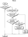
- FIG. 5 is a flowchart illustrating one example of a processing procedure for automatic stopping processes of the tractor 1. It is assumed that, when receiving the first signal sent from the portable communication terminal 3 via the first communication system R1 or a travel instruction signal sent from the remote controller 2 via the third communication system R3, the vehicle controller 100 according to the present embodiment sets a travel instruction flag.
- the vehicle controller 100 first determines whether or not there exists the above travel instruction flag (Step S110). When determining that there exists no travel instruction flag (Step S110: No), the vehicle controller 100 terminates the process. On the other hand, when determining that there exists the travel instruction flag (Step S110: Yes), the vehicle controller 100 outputs a travel instruction (Step S120). In other words, the vehicle controller 100 drives the automatic travelling unit 160 so as to cause the tractor 1 to start.
- the vehicle controller 100 determines whether or not there exists a detection signal by the second communication system R2 (Step S130).
- existence of a detection signal by the second communication system R2 indicates the fact that the possibility that the worker M carrying the portable communication terminal 3 exists in the automatic stop area S illustrated in FIG. 1 is high.
- Step S130 when determining that there exists a detection signal by the second communication system R2 (Step S130: Yes), the vehicle controller 100 shifts the process to Step S170, executes a vehicle stopping process, and stops the travel of the tractor 1. Specifically, the vehicle controller 100 drives the brake solenoids 330 so as to drive the brake cylinders 311, and operates the brake devices 312 (see FIG. 2 ).
- Step S130 when determining that there exists no detection signal by the second communication system R2 (Step S130: No), the vehicle controller 100 determines whether or not there exist various instructions by another communication system (Step S140). For example, the vehicle controller 100 determines whether or not there exists a vehicle stopping signal sent from the portable communication terminal 3 via the first communication system R1, or there exists various instruction signals sent from the remote controller 2 via the third communication system R3.
- Step S140 When determining that there exist no various instruction signals sent from another communication system (Step S140: No), the vehicle controller 100 terminates the process. On the other hand, when determining that there exist various instruction signals sent from another communication system (Step S140: Yes), the vehicle controller 100 determines whether or not the signals includes a stop instructing signal (Step S150).
- Step S150 when the received signals do not include a stop instructing signal (Step S150: No), the vehicle controller 100 executes processes according to the received instruction signals (Step S160).
- the vehicle controller 100 changes an output of the engine 321
- the vehicle controller 100 increases or decreases the rotation speed of the PTO shaft 392, for example, and terminates the process.
- Step S150 when the received signals include a stop instructing signal (Step S150: Yes), the vehicle controller 100 shifts the process to Step S170 so as to execute a vehicle stopping process, and stops the tractor 1 at once.
- Step S170 a stopping process of the work part may be executed simultaneously with the vehicle stopping process.
- the drive of the PTO shaft 392 is stopped that extracts the power to the work part from the engine 321.
- the drive stopping process of the PTO shaft 392 may be sequentially executed just after the vehicle stopping process, not simultaneously with a vehicle stop.
- the safety of the tractor 1 according to the present embodiment is able to be highly improved even when the automatic drive is performed.
- Step S130 the order of the process of Step S130 and that of Step S140 may be exchanged.
- tractor 1 work vehicle
- automatic stop system of the tractor 1 are realized.
- a work vehicle includes: (i) the travelling vehicle body 10 that includes the engine 321 as a power source to a work part and a travel part; (ii) the communication unit 110 that is able to transmit and receive signals to and from the portable communication terminal 3; (iii) the vehicle controller 100 that is able to control the travel part on the basis of a signal transmitted from the portable communication terminal 3 and received by the communication unit 110.
- the plurality of communication systems R is provided between the communication unit 110 and the portable communication terminal 3.
- the plurality of communication systems R includes: (i) the first communication system R1 that is able to transmit a first signal from the portable communication terminal 3; and (ii) the second communication system R2 that has a smaller communication area than that of the first communication system R1 and is able to receive a second signal.
- the second signal indicates that the portable communication terminal 3 exists in the predetermined area S.
- a work vehicle includes: (i) the travelling vehicle body 10 that includes the engine 321 as a power source to a work part and a travel part; (ii) the communication unit 110 that is able to transmit and receive signals to and from the portable communication terminal 3 so as to receive a first signal based on a remote operation of the portable communication terminal 3, and to receive a second signal indicating that the portable communication terminal 3 exists in a predetermined area; and (iii) the vehicle controller 100 that is able to control the travel part on the basis of one of the first and second signals transmitted from the portable communication terminal 3 and received by the communication unit 110.
- An automatic stop system of a work vehicle includes: (i) a work vehicle that includes a travel part, such as the tractor 1; (ii) the portable communication terminal 3; (iii) the communication unit 110 that is able to transmit and receive signals to and from the portable communication terminal 3 via the plurality of communication systems R; and (iv) the travelling system controller 120 as a travel stopping unit that stops a travel of the work vehicle on the basis of a signal transmitted from the portable communication terminal 3 and received by the communication unit 110.
- the plurality of communication systems R includes: (i) the first communication system R1 that is able to transmit a first signal, which is for stopping a travel of the work vehicle, from the portable communication terminal 3 to the work vehicle; and (ii) the second communication system R2 that has a smaller communication area than that of the first communication system R1 and is able to receive a second signal indicating that the portable communication terminal 3 exists in the predetermined area S.
- An automatic stop system of a work vehicle includes: (i) the travelling vehicle body 10 that includes the engine 321 as a power source to a work part and a travel part; (ii) the portable communication terminal 3; (iii) the communication unit 110 that is able to transmit and receive signals to and from the portable communication terminal 3; and (iv) the vehicle controller 100 that includes the travelling system controller 120.
- the travelling system controller 120 is able to control the travel part on the basis of a signal transmitted from the portable communication terminal 3 and received by the communication unit 110, performs a control for stopping the travelling vehicle body 10 on the basis of a first signal based on a remote operation of the portable communication terminal 3, and performs a control for stopping the travelling vehicle body 10 on the basis of a reception of a second signal indicating that the portable communication terminal 3 exists in a predetermined area.
Landscapes
- Engineering & Computer Science (AREA)
- General Physics & Mathematics (AREA)
- Physics & Mathematics (AREA)
- Aviation & Aerospace Engineering (AREA)
- Automation & Control Theory (AREA)
- Remote Sensing (AREA)
- Radar, Positioning & Navigation (AREA)
- Mechanical Engineering (AREA)
- Transportation (AREA)
- Structural Engineering (AREA)
- General Engineering & Computer Science (AREA)
- Civil Engineering (AREA)
- Mining & Mineral Resources (AREA)
- Control Of Position, Course, Altitude, Or Attitude Of Moving Bodies (AREA)
- Guiding Agricultural Machines (AREA)
- Agricultural Machines (AREA)
Description
- The embodiment discussed herein is directed to a work vehicle and an automatic stop system of the work vehicle.
- Conventionally, there is known a configuration in which a sensor for detecting an obstacle is provided in a work vehicle, which is able not only to travel automatically but also to travel by a remote operation by using a transmitter, and the vehicle automatically stops when the sensor detects an obstacle.
- Literature related to the conventional technique is Japanese Laid-open Patent Publication No.
62-297909 - However, for reliably detecting an obstacle by using the sensor, the detection is to be performed in all directions, and thus a plurality of sensors is to be provided in the work vehicle. Moreover, there exists a fear for failing to detect an obstacle in some cases.
- Further literature is disclosed in document
US 2006/0271263 A1 describing a determination of remote control operator position. Further literature is disclosed in documentUS 2010/ 063652 A1 describing garment for use near autonomous machines and in documentUS 2010/ 106344 A1 describing unmanned land vehicle having universal interfaces for attachments and autonomous operation capabilities and method of operation thereof. - It is an object of the present disclosure to at least partially solve the problems in the conventional technology. The present invention is described in the independent claim and further developed in the corresponding sub-claims.
- A more complete appreciation of the present disclosure and many of the attendant advantages thereof will be readily obtained as the same becomes better understood by reference to the following detailed description when considered in connection with the accompanying drawings, wherein:
-
FIG. 1 is a diagram illustrating an automatic stop system of a work vehicle according to an embodiment; -
FIG. 2 is a diagram illustrating the work vehicle according to the embodiment; -
FIG. 3 is a diagram illustrating a power transmitting path of the work vehicle; -
FIG. 4 is a control block diagram mainly illustrating a vehicle controller in the automatic stop system of the work vehicle according to the embodiment; and -
FIG. 5 is a flowchart illustrating one example of a processing procedure for automatic stopping processes of the work vehicle according to the embodiment. - Hereinafter, an embodiment of the present disclosure will be described in detail with reference to the accompanying drawings. In the following embodiment, a work vehicle will be explained to be a tractor 1. The components in the following embodiment include ones that can easily be envisioned by those skilled in the art, substantially the same ones, and ones in what is called a range of equivalents. The present invention is not limited by the following embodiment.
-
FIG. 1 is a diagram illustrating an automatic stop system of the tractor 1 according to the embodiment.FIG. 2 is a diagram illustrating the tractor 1.FIG. 3 is a diagram illustrating a power transmitting path of the tractor 1.FIG. 4 is a control block diagram mainly illustrating avehicle controller 100 in the automatic stop system of the tractor 1. - As illustrated in
FIG. 1 , the automatic stop system of the tractor 1 according to the embodiment includes the tractor 1, acommunication unit 110 that is provided in the tractor 1, aportable communication terminal 3 that is carried by a first worker M1, and thevehicle controller 100 that functions as a travel stopping unit. When thecommunication unit 110 receives a signal from theportable communication terminal 3, the travel stopping unit is able to stop a travel of the tractor 1 even when the tractor 1 is unmanned. In the present embodiment, the system includes aremote controller 2 that is able to perform a remote operation on the tractor 1. A second worker M2 is assumed to carry theremote controller 2. Hereinafter, the workers may be collectively referred to as "workers M". - The
communication unit 110 of this automatic stop system includes afirst communication unit 111, asecond communication unit 112, and athird communication unit 113. Thecommunication unit 110 is able to communicate with theportable communication terminal 3 by using a first communication system R1 via thefirst communication unit 111 and by using a second communication system R2 via thesecond communication unit 112. Thecommunication unit 110 is able to communicate with theremote controller 2 by using a third communication system R3 via thethird communication unit 113. - In other words, the
portable communication terminal 3 is able to communicate with the tractor 1 by using a plurality of communication systems R including the first communication system R1 and the second communication system R2 (seeFIG. 4 ). The first communication system R1 is able to transmit a stop signal. A communication area of the second communication system R2 is smaller than that of the first communication system R1, and is able to receive a detection signal indicating that theportable communication terminal 3 exists in a predetermined area. - A communication area of the third communication system R3, which connects the
remote controller 2 and thecommunication unit 110, is defined to be larger than at least of that of the second communication system R2, and the second worker M2 is able to perform a remote operation by using theremote controller 2 with respect to a travel, a work, etc. of the tractor 1. - A short-distance radio communication standard is employed for the second communication system R2 among the plurality of communication systems R that connect the tractor 1 and the
portable communication terminal 3. When receiving a second signal indicating that theportable communication terminal 3 exists in an automatic stop area S during travelling of atravelling vehicle body 10, thevehicle controller 100 of the tractor 1 is configured to cause thetravelling vehicle body 10 to stop travelling. It is needless to say that the length of the automatic stop area S is approximate to that of a communicable area of the second communication system R2. - In this manner, a wireless communication standard, which has a larger communication area than that of the short-distance radio communication standard employed for the second communication system R2, is employed for the first communication system R1. When the
first communication unit 111 of thecommunication unit 110 receives a first signal during travelling of the tractor 1, thevehicle controller 100 stops the travelling. - In other words, by employing a travel stopping system of the tractor 1 according to the present embodiment, a remote operation is able to be performed on the tractor 1 with respect to a travel or a travel stop by using a signal transmitted from the
remote controller 2, moreover, the travel stop is performed by a signal from not only theremote controller 2 but also theportable communication terminal 3. In other words, thevehicle controller 100 performs an urgent stop when thecommunication unit 110 receives the first signal or the second signal. - Hereinafter, functions of the travel stopping system of the tractor 1 according to the present embodiment will be simply explained. As illustrated in
FIG. 1 , it is assumed that the worker M2 operates theremote controller 2 in a position exceeding at least the automatic stop area S so as to cause the unmanned tractor 1 to start at a predetermined speed, for example. - It is assumed that the tractor 1 advances to reach the automatic stop area S. In a case where the first worker M1 that carries the
portable communication terminal 3 is in the automatic stop area S, when receiving the second signal sent from theportable communication terminal 3, the unmanned tractor 1 is automatically stopped. In other words, even when the second worker M2 carrying theremote controller 2 does not find the existence of the first worker M1, the unmanned tractor 1 is able to be automatically stopped when receiving the second signal sent from theportable communication terminal 3. - In this manner, the travel stopping system of the tractor 1 according to the present embodiment is able to detect the fact that the
portable communication terminal 3 exists in the near distance, in addition to a signal transmitted from theremote controller 2 that is for stopping the tractor 1 by using a remote operation. Therefore, when the tractor 1 is caused to automatically travel in a field etc., a risk in the neighborhood of thetravelling vehicle body 10 is able to be previously detected by the tractor 1 side so as to cause the tractor 1 to automatically stop, so that it is possible to contribute to improvement in the safety of the automatically-travelling tractor 1. - A configuration of the tractor 1 according to the present embodiment will be explained. The tractor 1 including the
travelling vehicle body 10 further includes thevehicle controller 100 and thecommunication unit 110 as illustrated inFIG. 4 . Thetravelling vehicle body 10 includes a steering handle (not illustrated), an operation pedal (not illustrated), and a maneuvering part provided with various instruments, and is configured so that a rear part of thetravelling vehicle body 10 is able to be connected with a work part including a working machine or a working device (not illustrated). A Differential Global Positioning System (DGPS) antenna 6 (seeFIG. 1 ), which receives radio waves transmitted from a plurality of navigation satellites, is placed on a ceiling part of thetravelling vehicle body 10. - The
vehicle controller 100 is constituted of a computer, and is able to control, by using electronic control, various units of the tractor 1 such as anautomatic travelling unit 160. Thecommunication unit 110 is able to communicate with theremote controller 2 and theportable communication terminal 3 in a wireless manner. - The tractor 1 includes various mechanisms such as power transmitting mechanisms illustrated in
FIGS. 2 and3 . In other words, as illustrated inFIG. 2 , the tractor 1 includes, on the respective left and right sides of thetravelling vehicle body 10, (i)front wheels front axles rear wheels rear axles front wheel 301, arear wheel 302, etc. - On a front part of the
travelling vehicle body 10, anengine 321 as a power source is mounted, and the power is transmitted from thisengine 321 to thefront wheels 301 and therear wheels 302 via the power transmitting mechanism. The tractor 1 according to the present embodiment includes a 4-wheel-drive (4WD)clutch 324, and is configured to be able to switch between (i) a 2-wheel-drive (2WD) type in which only therear wheels 302 are driven and (ii) a 4WD type in which thefront wheels 301 along with therear wheels 302 are driven, caused by switching of the4WD clutch 324. - In the power transmitting mechanism to the
rear wheels 302, amain transmission unit 323 is arranged in a subsequent stage of theengine 321 while placing an advance/reverse clutch 322 therebetween, asub-transmission unit 325 is arranged in a subsequent stage of themain transmission unit 323, and a rear-wheeldifferential gear device 326 is arranged in a subsequent stage of thesub-transmission unit 325. Brake devices 312 are arranged in bases of the rear axles 405 that connect the rear-wheeldifferential gear device 326 and therear wheels 302 with one another. - In the power transmitting mechanism to the
front wheels 301, atransmission shaft 404 is arranged in the subsequent stage of thesub-transmission unit 325. The power is transmitted to thetransmission shaft 404 via idle gears. The power transmitting mechanism is configured so that the power is transmitted from thetransmission shaft 404 to thefront wheels 301 via the4WD clutch 324 and a front-wheeldifferential gear device 320. - The tractor 1 according to the present embodiment includes the automatic travelling unit 160 (see
FIG. 4 ), which is controlled by thevehicle controller 100, so as to travel automatically. A steering-angle sensor 304, which detects a steering angle of thefront wheels 301, is connected to thevehicle controller 100. Thevehicle controller 100 controls, during automatic travelling, asteering cylinder 303 while feed-backing the detected actual steering angle of thefront wheels 301 so that the tractor 1 performs steering. - When an operator depresses a brake pedal 310 that is provided in a machine body, brake cylinders 311 are driven by hydraulic pressure, and the brake devices 312 functions that are provided to the
rear wheels 302. In other words, theleft brake device 312L arranged in the base of the leftrear axle 405L is connected with theleft brake cylinder 311L and theright brake device 312R arranged in the base of the rightrear axle 405R is connected with theright brake cylinder 311R. - As illustrated in
FIG. 2 , the left andright brake cylinders right brake solenoids vehicle controller 100. Thus, when a predetermined brake signal is input to thevehicle controller 100, thevehicle controller 100 drives at least one of the brake solenoids 330 to operate one or both of the left andright brake devices hydraulic pump 341, arelief valve 340, etc. - Next, with reference to
FIG. 3 , the power transmitting path of the tractor 1 from theengine 321 to thefront wheels 301 and therear wheels 302 will be explained. As illustrated inFIG. 3 , an output shaft of theengine 321 is connected with a power transmitting shaft via the advance/reverse clutch 322 for switching between advance and reverse. Therefore, the tractor 1 switches the advance/reverse clutch 322 to be able to selectively rotate the power transmitting shaft in a normal or reverse direction. - The power transmitting shaft is connected with the
main transmission unit 323 and thesub-transmission unit 325. Themain transmission unit 323 is provided with (i) a 1-speed/3-speed switching clutch 402 including a firstclutch gear 361 and a thirdclutch gear 363 and (ii) a 2-speed/4-speed switching clutch 403 including a secondclutch gear 362 and a fourthclutch gear 364 to be able to change the power that is output from theengine 321 into any one of the 1-speed to the 4-speed and output the changed power. - Moreover, the
main transmission unit 323 is provided with a high/low clutch 365. Thus, themain transmission unit 323 is able to switch each of the 1-speed to the 4-speed into a fast or low speed. - The
sub-transmission unit 325, to which the power of themain transmission unit 323 is input, includes afirst shifter 381 and asecond shifter 382 of double-sequential sub-transmission clutches to be operated by using a sub-transmission lever (not illustrated), and a plurality of transmission gears. With which transmission gear thefirst shifter 381 and thesecond shifter 382 engage changes the speed into any one of a super-low speed, a low speed, a middle speed, and a high speed. Rotation of an output shaft of thesub-transmission unit 325 is transmitted to therear wheels 302 from the rear-wheeldifferential gear device 326 via the axles and a rear-wheel planetary-gear mechanism 391. - The power, which is input from the
main transmission unit 323 to thesub-transmission unit 325, is input via the idle gears to thetransmission shaft 404 provided with the4WD clutch 324, whereby transmission of a driving force to thefront wheels 301 is performed. Switching into an accelerated front-wheel drive from a common front-wheel drive is able to be performed by effects of the4WD clutch 324. When the4WD clutch 324 is put into neutral, drive of thefront wheels 301 is severed and only the rear wheels are driven (namely, 2WD). - The power transmitted to subsequent-stage parts of the
4WD clutch 324 is transmitted to thefront wheels 301 via the front-wheeldifferential gear device 320 and a front-wheel planetary-gear mechanism 390. - The tractor 1 as a work vehicle includes a Power Take Off (PTO)
clutch 366. The tractor 1 connects the PTO clutch 366 to be able to transmit the power output from theengine 321 into aPTO shaft 392. - A first PTO-
transmission shifter 371 and a second PTO-transmission shifter 372 are arranged in a prior stage of thePTO shaft 392. When the first PTO-transmission shifter 371 and the second PTO-transmission shifter 372 are operated, thePTO shaft 392 is able to be rotated in the normal direction at a speed from a low speed to a high speed, moreover, is able to be rotated in the reverse direction. - Next, with reference to
FIG. 4 , a control system of the automatic stop system of the tractor 1 will be explained. As illustrated inFIG. 4 , the tractor 1 according to the present embodiment is able to control the units by using an electronic control, and includes thevehicle controller 100 that is the core of the control system. Thevehicle controller 100 receives an instruction signal sent from, for example, theremote controller 2 or theportable communication terminal 3 via thecommunication unit 110, and controls the automatic travellingunit 160 to be able to perform an automatic travel. - The
vehicle controller 100 included in the tractor 1 includes astorage 140, and a plurality ofcontrollers storage 140 is constituted of a hard disk, a Read Only Memory (ROM), a Random Access Memory (RAM), etc., in which various programs and needed data are stored. Each of thecontrollers - There exist, as the
controllers system controller 120 for controlling a travel system, theengine controller 130 for controlling theengine 321, the workingsystem controller 150 for controlling a work part such as a tiller to be connected with a rear part of the machine body, etc. - A processing unit that includes a CPU; a storage that includes a ROM for storing control programs, a RAM for a work region, etc.; and an input/output unit are provided to any of the travelling
system controller 120, theengine controller 130, and the workingsystem controller 150. The processing unit, the corresponding storage, and the corresponding input/output unit are connected with each other to be able to send and receive a signal to and from each other. The control programs etc. according to a controlling target of each of thecontrollers - To the
vehicle controller 100, anemergency stop switch 210, a motor (not illustrated) for steering drive, and atravel driving apparatus 220 including the transmission mechanisms illustrated inFIGS. 2 and3 are connected. Furthermore, to thevehicle controller 100, a group of obstacle detecting sensors such as (i) front and rear cameras (not illustrated) mounted on the tractor 1 and (ii) a corner detecting sonar; and various travel-system sensors 230 such as a steering-angle detecting sensor (not illustrated) for detecting a turning angle of the steering handle are connected. Furthermore, to thevehicle controller 100, a navigation system including the DGPS antenna 6 (seeFIG. 1 ), a direction sensor, a vehicle-speed sensor, etc. are connected. - To the
vehicle controller 100, a working-machine up-and-downdriving apparatus 240 that includes a working-machine up-and-down device (not illustrated) etc. and a PTO ON/OFF operating switch 250 for performing an operation of turning ON and OFF on the PTO clutch 366 are connected. To thevehicle controller 100, various working machine system/PTO driving sensors 260 for controlling a work part or a device associated with the PTO, anengine driving apparatus 270,various sensors 280 for driving the engine, etc. are connected. - In this manner, a worker gets on the machine body to cause the tractor 1 to perform a predetermined work while travelling by the tractor 1, moreover, for example, operates the
remote controller 2 so as to cause thevehicle controller 100 to control the driving of the automatic travellingunit 160, whereby the tractor 1 is able to perform a predetermined work while travelling automatically. - When causing the tractor 1 to travel automatically, a scheduled traveling route according to work contents is preliminary decided for each field, for example, and the corresponding route is digitized to be stored in the
storage 140. This scheduled traveling route is set in accordance with a shape and the size of a field; the width, the length, and the number of ridges formed in the field; a type of a crop; etc. - The automatic travel of the tractor 1 may be appropriately set in other than the case where the
vehicle controller 100 is caused to perform the automatic travel via theremote controller 2 as described in the present embodiment. - The
portable communication terminal 3, which is connected to thevehicle controller 100 of the tractor 1 by using the plurality of communication systems R, includes astorage 31, adisplay 32, and anoperation unit 33. Thestorage 31 is constituted of, for example, a ROM (Read Only Memory), a RAM (Random Access Memory), etc. and thedisplay 32 and theoperation unit 33 are constituted of, for example, a touch panel. Theoperation unit 33 may be provided with various keys and buttons etc. - The plurality of communication systems R, which is able to transmit and receive signals between the
portable communication terminal 3 and thevehicle controller 100, includes the first communication system R1 for transmitting and receiving the first signal and the second communication system R2 for transmitting and receiving the second signal. The short-distance radio communication standard is used in the second communication system R2, which has a smaller communication area than at least that of the first communication system R1. - The
vehicle controller 100 is configured to stop travelling of the travellingvehicle body 10 and further to stop driving of thePTO shaft 392 that extracts the power to the work part from theengine 321 when receiving the second signal during travelling of the travellingvehicle body 10. - Therefore, when the
portable communication terminal 3 exists in the neighborhood of the tractor 1, the travel of the tractor 1 is able to be automatically stopped and the drive of thePTO shaft 392 is also able to be stopped. Thus, it is possible to improve the safety in the automatic travel of the tractor 1. - In a case where the travelling
vehicle body 10 is travelling, when receiving the first signal sent from theportable communication terminal 3 that is carried by the worker M existing out of the automatic stop area S, thevehicle controller 100 also stops the travel of the travellingvehicle body 10. Thevehicle controller 100 simultaneously stops the drive of thePTO shaft 392 that extracts the power to the work part from theengine 321. - Moreover, the worker M is able to operate, by using the
portable communication terminal 3, with respect to the stop of the tractor 1 even from a position that is comparatively far away from the tractor 1. Moreover, in this case, the work part is also stopped, and thus it is possible to more improve the safety. - Next, a configuration of the
remote controller 2 that is able to perform a remote operation on the tractor 1 will be explained. As illustrated inFIG. 4 , theremote controller 2 is able to communicate with thethird communication unit 113 of the tractor 1 in a wireless manner by using the third communication system R3. Theremote controller 2 includes an operation unit. The operation unit includes an advance "ON/OFF"switch 21 and reverse "ON/OFF"switch 22 that are for causing the tractor 1 to travel, an ENG rotation-speed switch 24 for switching rotation speeds of theengine 321, and avehicle stopping switch 26 by which the tractor 1 is able to be urgently stopped. - The
remote controller 2 includes a PTO "ON/OFF"switch 23 and a working machine "UP/DOWN"switch 25 for operating a work part. - In this manner, the worker M operates the
remote controller 2 to be able to cause the tractor 1 to advance or reverse at a predetermined speed and further to stop, moreover, to be able to raise a work part and cause the work part to work at a predetermined power. - A stopping process of the tractor 1 and the automatic stop system of the tractor 1 having the above configurations will be explained with reference to
FIG. 5. FIG. 5 is a flowchart illustrating one example of a processing procedure for automatic stopping processes of the tractor 1. It is assumed that, when receiving the first signal sent from theportable communication terminal 3 via the first communication system R1 or a travel instruction signal sent from theremote controller 2 via the third communication system R3, thevehicle controller 100 according to the present embodiment sets a travel instruction flag. - As illustrated in
FIG. 5 , thevehicle controller 100 first determines whether or not there exists the above travel instruction flag (Step S110). When determining that there exists no travel instruction flag (Step S110: No), thevehicle controller 100 terminates the process. On the other hand, when determining that there exists the travel instruction flag (Step S110: Yes), thevehicle controller 100 outputs a travel instruction (Step S120). In other words, thevehicle controller 100 drives the automatic travellingunit 160 so as to cause the tractor 1 to start. - Next, the
vehicle controller 100 determines whether or not there exists a detection signal by the second communication system R2 (Step S130). In other words, existence of a detection signal by the second communication system R2 indicates the fact that the possibility that the worker M carrying theportable communication terminal 3 exists in the automatic stop area S illustrated inFIG. 1 is high. - Therefore, when determining that there exists a detection signal by the second communication system R2 (Step S130: Yes), the
vehicle controller 100 shifts the process to Step S170, executes a vehicle stopping process, and stops the travel of the tractor 1. Specifically, thevehicle controller 100 drives the brake solenoids 330 so as to drive the brake cylinders 311, and operates the brake devices 312 (seeFIG. 2 ). - On the other hand, in Step S130, when determining that there exists no detection signal by the second communication system R2 (Step S130: No), the
vehicle controller 100 determines whether or not there exist various instructions by another communication system (Step S140). For example, thevehicle controller 100 determines whether or not there exists a vehicle stopping signal sent from theportable communication terminal 3 via the first communication system R1, or there exists various instruction signals sent from theremote controller 2 via the third communication system R3. - When determining that there exist no various instruction signals sent from another communication system (Step S140: No), the
vehicle controller 100 terminates the process. On the other hand, when determining that there exist various instruction signals sent from another communication system (Step S140: Yes), thevehicle controller 100 determines whether or not the signals includes a stop instructing signal (Step S150). - In Step S150, when the received signals do not include a stop instructing signal (Step S150: No), the
vehicle controller 100 executes processes according to the received instruction signals (Step S160). In other words, when the instruction signals include an acceleration or deceleration instruction, thevehicle controller 100 changes an output of theengine 321, when the instruction signals include an instruction signal associated with an output of the work part, thevehicle controller 100 increases or decreases the rotation speed of thePTO shaft 392, for example, and terminates the process. - In Step S150, when the received signals include a stop instructing signal (Step S150: Yes), the
vehicle controller 100 shifts the process to Step S170 so as to execute a vehicle stopping process, and stops the tractor 1 at once. - Although omitted in
FIG. 5 , in Step S170, a stopping process of the work part may be executed simultaneously with the vehicle stopping process. In other words, the drive of thePTO shaft 392 is stopped that extracts the power to the work part from theengine 321. - The drive stopping process of the
PTO shaft 392 may be sequentially executed just after the vehicle stopping process, not simultaneously with a vehicle stop. - By executing the above processes, the safety of the tractor 1 according to the present embodiment is able to be highly improved even when the automatic drive is performed.
- Among the above processes, the order of the process of Step S130 and that of Step S140 may be exchanged.
- According to the above embodiment, the following tractor 1 (work vehicle) and the automatic stop system of the tractor 1 are realized.
- (1) A work vehicle includes: (i) the travelling
vehicle body 10 that includes theengine 321 as a power source to a work part and a travel part; (ii) thecommunication unit 110 that is able to transmit and receive signals to and from theportable communication terminal 3; (iii) thevehicle controller 100 that is able to control the travel part on the basis of a signal transmitted from theportable communication terminal 3 and received by thecommunication unit 110. The plurality of communication systems R is provided between thecommunication unit 110 and theportable communication terminal 3. The plurality of communication systems R includes: (i) the first communication system R1 that is able to transmit a first signal from theportable communication terminal 3; and (ii) the second communication system R2 that has a smaller communication area than that of the first communication system R1 and is able to receive a second signal. The second signal indicates that theportable communication terminal 3 exists in the predetermined area S. - By employing the work vehicle (tractor 1) in (1), it is possible to detect the fact that the
portable communication terminal 3 exists in the near distance, in addition to the signal transmitted by the remote operation. It is accordingly possible to previously detect a risk in the neighborhood of the vehicle to be able to contribute to improvement in the safety. - (2) The work vehicle in (1), in which a short-distance radio communication standard is employed for the second communication system R2, and the
vehicle controller 100 stops a travel of the travellingvehicle body 10 when receiving the second signal during the travel of the travellingvehicle body 10. - By employing the work vehicle (tractor 1) in (2), it is possible to cause the tractor 1 to automatically stop when the
portable communication terminal 3 exists in the near distance. It is accordingly possible to more improve the safety, in addition to an effect of the work vehicle in (1). - (3) The work vehicle in (2), in which the
vehicle controller 100 stops a drive of thePTO shaft 392 that extracts a power to the work part from theengine 321, when receiving the second signal. - By employing the work vehicle (tractor 1) in (3), it is possible to stop driving the PTO shaft when the vehicle is automatically stopped, for example, to be able to stop operation of the work part. It is accordingly possible to more improve the safety, in addition to an effect of the work vehicle in (2).
- (4) The work vehicle in (2) or (3), in which a communication standard, which has a larger communication area than that of the short-distance radio communication standard, is employed for the first communication system R1, and the
vehicle controller 100 stops the travel of the travellingvehicle body 10 when receiving the first signal during the travel of the travellingvehicle body 10. - By employing the work vehicle in (tractor 1) (4), it is possible to cause the work vehicle to stop by using the remote operation even when the worker M1 does not approach the work vehicle (tractor 1), for example, in addition to an effect of the work vehicle in (2) and (3).
- (5) The work vehicle in (4), in which the
vehicle controller 100 stops a drive of thePTO shaft 392 that extracts a power to the work part from theengine 321, when receiving the first signal. - By employing the work vehicle (tractor 1) in (5), it is possible to stop the operation of the work part when the vehicle is stopped by the remote operation. It is accordingly possible to more improve the safety, in addition to an effect of the work vehicle in (4).
- (6) A work vehicle includes: (i) the travelling
vehicle body 10 that includes theengine 321 as a power source to a work part and a travel part; (ii) thecommunication unit 110 that is able to transmit and receive signals to and from theportable communication terminal 3 so as to receive a first signal based on a remote operation of theportable communication terminal 3, and to receive a second signal indicating that theportable communication terminal 3 exists in a predetermined area; and (iii) thevehicle controller 100 that is able to control the travel part on the basis of one of the first and second signals transmitted from theportable communication terminal 3 and received by thecommunication unit 110. - By employing the work vehicle (tractor 1) in (6), it is possible to secure the safety even when the worker M1 carrying the
portable communication terminal 3 is in the neighborhood of the tractor 1, and to control the tractor 1 by using the remote control when the worker M1 is far from the tractor 1. - (7) An automatic stop system of a work vehicle includes: (i) a work vehicle that includes a travel part, such as the tractor 1; (ii) the
portable communication terminal 3; (iii) thecommunication unit 110 that is able to transmit and receive signals to and from theportable communication terminal 3 via the plurality of communication systems R; and (iv) the travellingsystem controller 120 as a travel stopping unit that stops a travel of the work vehicle on the basis of a signal transmitted from theportable communication terminal 3 and received by thecommunication unit 110. The plurality of communication systems R includes: (i) the first communication system R1 that is able to transmit a first signal, which is for stopping a travel of the work vehicle, from theportable communication terminal 3 to the work vehicle; and (ii) the second communication system R2 that has a smaller communication area than that of the first communication system R1 and is able to receive a second signal indicating that theportable communication terminal 3 exists in the predetermined area S. - By employing the work vehicle (tractor 1) in (7), it is possible to detect the fact that the portable communication terminal exists in the near distance, in addition to the signal transmitted by the remote operation. It is accordingly possible to previously detect a risk in the periphery and neighborhood of the vehicle to be able to contribute to improvement in the safety.
- (8) An automatic stop system of a work vehicle includes: (i) the travelling
vehicle body 10 that includes theengine 321 as a power source to a work part and a travel part; (ii) theportable communication terminal 3; (iii) thecommunication unit 110 that is able to transmit and receive signals to and from theportable communication terminal 3; and (iv) thevehicle controller 100 that includes the travellingsystem controller 120. The travellingsystem controller 120 is able to control the travel part on the basis of a signal transmitted from theportable communication terminal 3 and received by thecommunication unit 110, performs a control for stopping the travellingvehicle body 10 on the basis of a first signal based on a remote operation of theportable communication terminal 3, and performs a control for stopping the travellingvehicle body 10 on the basis of a reception of a second signal indicating that theportable communication terminal 3 exists in a predetermined area. - By employing the automatic stop system of the work vehicle (tractor 1) in (7), it is possible to secure the safety even when the worker M1 carrying the
portable communication terminal 3 is in the neighborhood of the tractor 1, and to control the tractor 1 by using the remote control when the worker M1 is far from the tractor 1.
Claims (6)
- A work vehicle (1) comprising:a travelling vehicle body (10) that includes a power source to a work part and a travel part; anda communication unit (110) that is mounted on the travelling vehicle body (10),the communication unit (110) comprising:directly receiving signals from a portable communication terminal (3) carried by a worker through a first communication system (R1) and a second communication system (R2) having smaller communication area than that of the first communication system (R1); andcontrolling the travelling vehicle body (10) based on the received signals from the portable communication terminal (3), whereinthe first communication system (R1) is for receiving the signals transmitted to the travelling vehicle body (10) from the portable communication terminal (3) based on the worker's input at the communication unit (110), and the second communication system (R2) is for automatically transmitting from the portable communication terminal (3) and receiving a detection signal by the communication unit (110) indicating that the portable communication terminal (3) exists in the communication area, anda short-distance radio communication standard is employed for the second communication system (R2),
characterized in thata control unit (100) automatically stops a travel of the travelling vehicle body (10) when receiving the second signal from said portable communication terminal (3) during the travel of the travelling vehicle body (10). - The work vehicle (1) according to claim 1, wherein
the control unit (100) stops a drive of a Power-Take-Off (PTO) shaft that extracts a power to the work part from the power source, when receiving the second signal. - The work vehicle (1) according to claim 1, wherein
a communication standard, which has a larger communication area than that of the short-distance radio communication standard, is employed for the first communication system (R1), and
the control unit (100) stops the travel of the travelling vehicle body (10) when receiving a signal from the portable communication terminal (3) via the first communication system (R1) during the travel of the travelling vehicle body (10). - The work vehicle (1) according to any one of claims 1 to 3, wherein
stopping signals transmitted depending on the worker's input from the portable communication terminal (3) through the first communication system (R1) are received, and the travelling vehicle body (10) is stopped when either the stopping signal or the detection signal is detected. - The work vehicle (1) according to any one of claims 1 to 4, wherein
a remote controller (2) for operating forward movement, backward movement and stopping of the travelling vehicle body (1) can wirelessly communicate with the communication unit (110) by the third communication system (R3), and processes are executed by the remote controller (2) through the third communication system (R3) when determining that there exists no detection signal by the second communication system (R2). - The work vehicle (1) according to any one of claims 1 to 5, wherein
the control unit (100) stops a drive of a Power-Take-Off (PTO) shaft that extracts a power to the work part from the power source after the travelling vehicle body (10) is stopped.
Applications Claiming Priority (1)
| Application Number | Priority Date | Filing Date | Title |
|---|---|---|---|
| JP2017063940A JP6880914B2 (en) | 2017-03-28 | 2017-03-28 | Work vehicle and automatic stop system for work vehicle |
Publications (2)
| Publication Number | Publication Date |
|---|---|
| EP3382487A1 EP3382487A1 (en) | 2018-10-03 |
| EP3382487B1 true EP3382487B1 (en) | 2020-10-28 |
Family
ID=61163494
Family Applications (1)
| Application Number | Title | Priority Date | Filing Date |
|---|---|---|---|
| EP18154336.4A Active EP3382487B1 (en) | 2017-03-28 | 2018-01-31 | Work vehicle and automatic stop system of work vehicle |
Country Status (3)
| Country | Link |
|---|---|
| US (1) | US10407873B2 (en) |
| EP (1) | EP3382487B1 (en) |
| JP (1) | JP6880914B2 (en) |
Families Citing this family (9)
| Publication number | Priority date | Publication date | Assignee | Title |
|---|---|---|---|---|
| US12143893B2 (en) | 2013-12-03 | 2024-11-12 | Sfara, Inc. | System and method for determining when smartphone is in vehicle |
| US11222534B2 (en) | 2013-12-20 | 2022-01-11 | Sfara, Inc. | System and method for smartphone communication during vehicle mode |
| US10919574B2 (en) * | 2015-11-10 | 2021-02-16 | Hyundai Motor Company | Automatic parking system and automatic parking method |
| FI131330B1 (en) * | 2017-11-24 | 2025-02-24 | Novatron Oy | Earthmoving machinery control |
| JP6919531B2 (en) * | 2017-11-30 | 2021-08-18 | 井関農機株式会社 | Work vehicle |
| JP7149205B2 (en) * | 2019-03-05 | 2022-10-06 | 日立建機株式会社 | self-driving work machine |
| US12353210B2 (en) | 2019-07-25 | 2025-07-08 | Ag Leader Technology | Apparatus, systems and methods for automated navigation of agricultural equipment |
| US12583509B1 (en) | 2020-05-18 | 2026-03-24 | Ag Leader Technology | Assisted steering apparatus and associated systems and methods |
| US12403950B2 (en) | 2021-04-19 | 2025-09-02 | Ag Leader Technology | Automatic steering systems and methods |
Family Cites Families (9)
| Publication number | Priority date | Publication date | Assignee | Title |
|---|---|---|---|---|
| JPS62297909A (en) | 1986-06-17 | 1987-12-25 | Kubota Ltd | Drive controller for automatic traveling truck |
| JP2000339029A (en) * | 1999-05-31 | 2000-12-08 | Komatsu Ltd | Vehicle interference prevention device |
| JP4036194B2 (en) * | 2004-01-15 | 2008-01-23 | トヨタ自動車株式会社 | Car alarm system and vehicle alarm system |
| DE602006006821D1 (en) * | 2005-05-27 | 2009-06-25 | Charles Machine Works | DETERMINING THE POSITION OF A REMOTE CONTROL USER |
| US20100063652A1 (en) * | 2008-09-11 | 2010-03-11 | Noel Wayne Anderson | Garment for Use Near Autonomous Machines |
| US20100106344A1 (en) * | 2008-10-27 | 2010-04-29 | Edwards Dean B | Unmanned land vehicle having universal interfaces for attachments and autonomous operation capabilities and method of operation thereof |
| JP5269578B2 (en) * | 2008-12-25 | 2013-08-21 | 京セラ株式会社 | Alarm device for vehicle, alarm method, and program |
| JP5580606B2 (en) * | 2010-01-13 | 2014-08-27 | 株式会社クボタ | PTO control system |
| JP2016095661A (en) * | 2014-11-13 | 2016-05-26 | ヤンマー株式会社 | Unmanned operation system |
-
2017
- 2017-03-28 JP JP2017063940A patent/JP6880914B2/en active Active
- 2017-11-13 US US15/810,216 patent/US10407873B2/en active Active
-
2018
- 2018-01-31 EP EP18154336.4A patent/EP3382487B1/en active Active
Non-Patent Citations (1)
| Title |
|---|
| None * |
Also Published As
| Publication number | Publication date |
|---|---|
| JP2018165969A (en) | 2018-10-25 |
| US20180282973A1 (en) | 2018-10-04 |
| JP6880914B2 (en) | 2021-06-02 |
| EP3382487A1 (en) | 2018-10-03 |
| US10407873B2 (en) | 2019-09-10 |
Similar Documents
| Publication | Publication Date | Title |
|---|---|---|
| US10407873B2 (en) | Work vehicle and automatic stop system of work vehicle | |
| EP3352036B1 (en) | Work vehicle wireless management system and method for controlling work traveling of a plurality of work vehicles | |
| US10939605B2 (en) | Controller for work machine, control method for work machine, and work machine | |
| US12457913B2 (en) | Automatic traveling system, automatic traveling method, and automatic traveling program | |
| JP2024174918A (en) | Autonomous driving system and method | |
| KR20220099533A (en) | Automated driving systems for work vehicles | |
| EP3410247B1 (en) | Master work vehicle performing work in cooperation with slave work vehicle | |
| EP3918894B1 (en) | Autonomous travel system for work vehicle | |
| EP3918893A1 (en) | Work vehicle automated travel system | |
| JP2023126466A (en) | Automatic traveling method and automatic traveling system | |
| JP2024053067A (en) | Autonomous driving system and method | |
| US20210207707A1 (en) | Operating device for a shift by wire assembly | |
| JP7094833B2 (en) | Travel route display device | |
| US11292484B2 (en) | Vehicle control device, vehicle, and vehicle control method | |
| JP7626822B2 (en) | Work vehicle wireless management system | |
| JP7484626B2 (en) | Braking system for work vehicles | |
| JP2020198789A (en) | Autonomously traveling work vehicle | |
| JP2019041619A (en) | Tilling work vehicle | |
| JP2019045975A (en) | Tilling work vehicle | |
| JP2024005901A (en) | Work vehicle management system |
Legal Events
| Date | Code | Title | Description |
|---|---|---|---|
| PUAI | Public reference made under article 153(3) epc to a published international application that has entered the european phase |
Free format text: ORIGINAL CODE: 0009012 |
|
| STAA | Information on the status of an ep patent application or granted ep patent |
Free format text: STATUS: REQUEST FOR EXAMINATION WAS MADE |
|
| 17P | Request for examination filed |
Effective date: 20180131 |
|
| AK | Designated contracting states |
Kind code of ref document: A1 Designated state(s): AL AT BE BG CH CY CZ DE DK EE ES FI FR GB GR HR HU IE IS IT LI LT LU LV MC MK MT NL NO PL PT RO RS SE SI SK SM TR |
|
| AX | Request for extension of the european patent |
Extension state: BA ME |
|
| STAA | Information on the status of an ep patent application or granted ep patent |
Free format text: STATUS: EXAMINATION IS IN PROGRESS |
|
| 17Q | First examination report despatched |
Effective date: 20190726 |
|
| REG | Reference to a national code |
Ref country code: DE Ref legal event code: R079 Ref document number: 602018009017 Country of ref document: DE Free format text: PREVIOUS MAIN CLASS: G05D0001000000 Ipc: B60T0007220000 |
|
| GRAP | Despatch of communication of intention to grant a patent |
Free format text: ORIGINAL CODE: EPIDOSNIGR1 |
|
| RIC1 | Information provided on ipc code assigned before grant |
Ipc: B60T 7/22 20060101AFI20200402BHEP Ipc: G05D 1/00 20060101ALI20200402BHEP |
|
| STAA | Information on the status of an ep patent application or granted ep patent |
Free format text: STATUS: GRANT OF PATENT IS INTENDED |
|
| INTG | Intention to grant announced |
Effective date: 20200507 |
|
| GRAS | Grant fee paid |
Free format text: ORIGINAL CODE: EPIDOSNIGR3 |
|
| GRAA | (expected) grant |
Free format text: ORIGINAL CODE: 0009210 |
|
| STAA | Information on the status of an ep patent application or granted ep patent |
Free format text: STATUS: THE PATENT HAS BEEN GRANTED |
|
| AK | Designated contracting states |
Kind code of ref document: B1 Designated state(s): AL AT BE BG CH CY CZ DE DK EE ES FI FR GB GR HR HU IE IS IT LI LT LU LV MC MK MT NL NO PL PT RO RS SE SI SK SM TR |
|
| REG | Reference to a national code |
Ref country code: GB Ref legal event code: FG4D |
|
| REG | Reference to a national code |
Ref country code: CH Ref legal event code: EP |
|
| REG | Reference to a national code |
Ref country code: AT Ref legal event code: REF Ref document number: 1327913 Country of ref document: AT Kind code of ref document: T Effective date: 20201115 |
|
| REG | Reference to a national code |
Ref country code: DE Ref legal event code: R096 Ref document number: 602018009017 Country of ref document: DE |
|
| REG | Reference to a national code |
Ref country code: IE Ref legal event code: FG4D |
|
| REG | Reference to a national code |
Ref country code: AT Ref legal event code: MK05 Ref document number: 1327913 Country of ref document: AT Kind code of ref document: T Effective date: 20201028 |
|
| REG | Reference to a national code |
Ref country code: NL Ref legal event code: MP Effective date: 20201028 |
|
| PG25 | Lapsed in a contracting state [announced via postgrant information from national office to epo] |
Ref country code: PT Free format text: LAPSE BECAUSE OF FAILURE TO SUBMIT A TRANSLATION OF THE DESCRIPTION OR TO PAY THE FEE WITHIN THE PRESCRIBED TIME-LIMIT Effective date: 20210301 Ref country code: RS Free format text: LAPSE BECAUSE OF FAILURE TO SUBMIT A TRANSLATION OF THE DESCRIPTION OR TO PAY THE FEE WITHIN THE PRESCRIBED TIME-LIMIT Effective date: 20201028 Ref country code: FI Free format text: LAPSE BECAUSE OF FAILURE TO SUBMIT A TRANSLATION OF THE DESCRIPTION OR TO PAY THE FEE WITHIN THE PRESCRIBED TIME-LIMIT Effective date: 20201028 Ref country code: NO Free format text: LAPSE BECAUSE OF FAILURE TO SUBMIT A TRANSLATION OF THE DESCRIPTION OR TO PAY THE FEE WITHIN THE PRESCRIBED TIME-LIMIT Effective date: 20210128 Ref country code: GR Free format text: LAPSE BECAUSE OF FAILURE TO SUBMIT A TRANSLATION OF THE DESCRIPTION OR TO PAY THE FEE WITHIN THE PRESCRIBED TIME-LIMIT Effective date: 20210129 |
|
| REG | Reference to a national code |
Ref country code: LT Ref legal event code: MG4D |
|
| PG25 | Lapsed in a contracting state [announced via postgrant information from national office to epo] |
Ref country code: BG Free format text: LAPSE BECAUSE OF FAILURE TO SUBMIT A TRANSLATION OF THE DESCRIPTION OR TO PAY THE FEE WITHIN THE PRESCRIBED TIME-LIMIT Effective date: 20210128 Ref country code: IS Free format text: LAPSE BECAUSE OF FAILURE TO SUBMIT A TRANSLATION OF THE DESCRIPTION OR TO PAY THE FEE WITHIN THE PRESCRIBED TIME-LIMIT Effective date: 20210228 Ref country code: LV Free format text: LAPSE BECAUSE OF FAILURE TO SUBMIT A TRANSLATION OF THE DESCRIPTION OR TO PAY THE FEE WITHIN THE PRESCRIBED TIME-LIMIT Effective date: 20201028 Ref country code: PL Free format text: LAPSE BECAUSE OF FAILURE TO SUBMIT A TRANSLATION OF THE DESCRIPTION OR TO PAY THE FEE WITHIN THE PRESCRIBED TIME-LIMIT Effective date: 20201028 Ref country code: SE Free format text: LAPSE BECAUSE OF FAILURE TO SUBMIT A TRANSLATION OF THE DESCRIPTION OR TO PAY THE FEE WITHIN THE PRESCRIBED TIME-LIMIT Effective date: 20201028 Ref country code: ES Free format text: LAPSE BECAUSE OF FAILURE TO SUBMIT A TRANSLATION OF THE DESCRIPTION OR TO PAY THE FEE WITHIN THE PRESCRIBED TIME-LIMIT Effective date: 20201028 Ref country code: AT Free format text: LAPSE BECAUSE OF FAILURE TO SUBMIT A TRANSLATION OF THE DESCRIPTION OR TO PAY THE FEE WITHIN THE PRESCRIBED TIME-LIMIT Effective date: 20201028 |
|
| PG25 | Lapsed in a contracting state [announced via postgrant information from national office to epo] |
Ref country code: HR Free format text: LAPSE BECAUSE OF FAILURE TO SUBMIT A TRANSLATION OF THE DESCRIPTION OR TO PAY THE FEE WITHIN THE PRESCRIBED TIME-LIMIT Effective date: 20201028 Ref country code: NL Free format text: LAPSE BECAUSE OF FAILURE TO SUBMIT A TRANSLATION OF THE DESCRIPTION OR TO PAY THE FEE WITHIN THE PRESCRIBED TIME-LIMIT Effective date: 20201028 |
|
| REG | Reference to a national code |
Ref country code: DE Ref legal event code: R097 Ref document number: 602018009017 Country of ref document: DE |
|
| PG25 | Lapsed in a contracting state [announced via postgrant information from national office to epo] |
Ref country code: SK Free format text: LAPSE BECAUSE OF FAILURE TO SUBMIT A TRANSLATION OF THE DESCRIPTION OR TO PAY THE FEE WITHIN THE PRESCRIBED TIME-LIMIT Effective date: 20201028 Ref country code: RO Free format text: LAPSE BECAUSE OF FAILURE TO SUBMIT A TRANSLATION OF THE DESCRIPTION OR TO PAY THE FEE WITHIN THE PRESCRIBED TIME-LIMIT Effective date: 20201028 Ref country code: SM Free format text: LAPSE BECAUSE OF FAILURE TO SUBMIT A TRANSLATION OF THE DESCRIPTION OR TO PAY THE FEE WITHIN THE PRESCRIBED TIME-LIMIT Effective date: 20201028 Ref country code: EE Free format text: LAPSE BECAUSE OF FAILURE TO SUBMIT A TRANSLATION OF THE DESCRIPTION OR TO PAY THE FEE WITHIN THE PRESCRIBED TIME-LIMIT Effective date: 20201028 Ref country code: CZ Free format text: LAPSE BECAUSE OF FAILURE TO SUBMIT A TRANSLATION OF THE DESCRIPTION OR TO PAY THE FEE WITHIN THE PRESCRIBED TIME-LIMIT Effective date: 20201028 Ref country code: LT Free format text: LAPSE BECAUSE OF FAILURE TO SUBMIT A TRANSLATION OF THE DESCRIPTION OR TO PAY THE FEE WITHIN THE PRESCRIBED TIME-LIMIT Effective date: 20201028 |
|
| PG25 | Lapsed in a contracting state [announced via postgrant information from national office to epo] |
Ref country code: MC Free format text: LAPSE BECAUSE OF FAILURE TO SUBMIT A TRANSLATION OF THE DESCRIPTION OR TO PAY THE FEE WITHIN THE PRESCRIBED TIME-LIMIT Effective date: 20201028 Ref country code: DK Free format text: LAPSE BECAUSE OF FAILURE TO SUBMIT A TRANSLATION OF THE DESCRIPTION OR TO PAY THE FEE WITHIN THE PRESCRIBED TIME-LIMIT Effective date: 20201028 |
|
| REG | Reference to a national code |
Ref country code: CH Ref legal event code: PL |
|
| PLBE | No opposition filed within time limit |
Free format text: ORIGINAL CODE: 0009261 |
|
| STAA | Information on the status of an ep patent application or granted ep patent |
Free format text: STATUS: NO OPPOSITION FILED WITHIN TIME LIMIT |
|
| PG25 | Lapsed in a contracting state [announced via postgrant information from national office to epo] |
Ref country code: LU Free format text: LAPSE BECAUSE OF NON-PAYMENT OF DUE FEES Effective date: 20210131 |
|
| 26N | No opposition filed |
Effective date: 20210729 |
|
| PG25 | Lapsed in a contracting state [announced via postgrant information from national office to epo] |
Ref country code: AL Free format text: LAPSE BECAUSE OF FAILURE TO SUBMIT A TRANSLATION OF THE DESCRIPTION OR TO PAY THE FEE WITHIN THE PRESCRIBED TIME-LIMIT Effective date: 20201028 Ref country code: IT Free format text: LAPSE BECAUSE OF FAILURE TO SUBMIT A TRANSLATION OF THE DESCRIPTION OR TO PAY THE FEE WITHIN THE PRESCRIBED TIME-LIMIT Effective date: 20201028 |
|
| PG25 | Lapsed in a contracting state [announced via postgrant information from national office to epo] |
Ref country code: SI Free format text: LAPSE BECAUSE OF FAILURE TO SUBMIT A TRANSLATION OF THE DESCRIPTION OR TO PAY THE FEE WITHIN THE PRESCRIBED TIME-LIMIT Effective date: 20201028 Ref country code: CH Free format text: LAPSE BECAUSE OF NON-PAYMENT OF DUE FEES Effective date: 20210131 Ref country code: LI Free format text: LAPSE BECAUSE OF NON-PAYMENT OF DUE FEES Effective date: 20210131 |
|
| PG25 | Lapsed in a contracting state [announced via postgrant information from national office to epo] |
Ref country code: IE Free format text: LAPSE BECAUSE OF NON-PAYMENT OF DUE FEES Effective date: 20210131 |
|
| PG25 | Lapsed in a contracting state [announced via postgrant information from national office to epo] |
Ref country code: IS Free format text: LAPSE BECAUSE OF FAILURE TO SUBMIT A TRANSLATION OF THE DESCRIPTION OR TO PAY THE FEE WITHIN THE PRESCRIBED TIME-LIMIT Effective date: 20210228 |
|
| PG25 | Lapsed in a contracting state [announced via postgrant information from national office to epo] |
Ref country code: CY Free format text: LAPSE BECAUSE OF FAILURE TO SUBMIT A TRANSLATION OF THE DESCRIPTION OR TO PAY THE FEE WITHIN THE PRESCRIBED TIME-LIMIT Effective date: 20201028 |
|
| PG25 | Lapsed in a contracting state [announced via postgrant information from national office to epo] |
Ref country code: HU Free format text: LAPSE BECAUSE OF FAILURE TO SUBMIT A TRANSLATION OF THE DESCRIPTION OR TO PAY THE FEE WITHIN THE PRESCRIBED TIME-LIMIT; INVALID AB INITIO Effective date: 20180131 |
|
| PG25 | Lapsed in a contracting state [announced via postgrant information from national office to epo] |
Ref country code: MK Free format text: LAPSE BECAUSE OF FAILURE TO SUBMIT A TRANSLATION OF THE DESCRIPTION OR TO PAY THE FEE WITHIN THE PRESCRIBED TIME-LIMIT Effective date: 20201028 |
|
| PGFP | Annual fee paid to national office [announced via postgrant information from national office to epo] |
Ref country code: BE Payment date: 20240122 Year of fee payment: 7 |
|
| PG25 | Lapsed in a contracting state [announced via postgrant information from national office to epo] |
Ref country code: MT Free format text: LAPSE BECAUSE OF FAILURE TO SUBMIT A TRANSLATION OF THE DESCRIPTION OR TO PAY THE FEE WITHIN THE PRESCRIBED TIME-LIMIT Effective date: 20201028 |
|
| PG25 | Lapsed in a contracting state [announced via postgrant information from national office to epo] |
Ref country code: BE Free format text: LAPSE BECAUSE OF NON-PAYMENT OF DUE FEES Effective date: 20250131 |
|
| REG | Reference to a national code |
Ref country code: BE Ref legal event code: MM Effective date: 20250131 |
|
| PG25 | Lapsed in a contracting state [announced via postgrant information from national office to epo] |
Ref country code: TR Free format text: LAPSE BECAUSE OF FAILURE TO SUBMIT A TRANSLATION OF THE DESCRIPTION OR TO PAY THE FEE WITHIN THE PRESCRIBED TIME-LIMIT Effective date: 20201028 |
|
| PGFP | Annual fee paid to national office [announced via postgrant information from national office to epo] |
Ref country code: GB Payment date: 20260122 Year of fee payment: 9 |
|
| PGFP | Annual fee paid to national office [announced via postgrant information from national office to epo] |
Ref country code: DE Payment date: 20260128 Year of fee payment: 9 |
|
| PGFP | Annual fee paid to national office [announced via postgrant information from national office to epo] |
Ref country code: FR Payment date: 20260127 Year of fee payment: 9 |