EP3382442A1 - Display apparatus - Google Patents
Display apparatus Download PDFInfo
- Publication number
- EP3382442A1 EP3382442A1 EP18163704.2A EP18163704A EP3382442A1 EP 3382442 A1 EP3382442 A1 EP 3382442A1 EP 18163704 A EP18163704 A EP 18163704A EP 3382442 A1 EP3382442 A1 EP 3382442A1
- Authority
- EP
- European Patent Office
- Prior art keywords
- laser
- display apparatus
- low output
- current
- output laser
- Prior art date
- Legal status (The legal status is an assumption and is not a legal conclusion. Google has not performed a legal analysis and makes no representation as to the accuracy of the status listed.)
- Withdrawn
Links
- 230000002207 retinal effect Effects 0.000 claims abstract description 13
- 230000003287 optical effect Effects 0.000 description 24
- 229920005994 diacetyl cellulose Polymers 0.000 description 18
- 238000001514 detection method Methods 0.000 description 11
- 238000000034 method Methods 0.000 description 8
- 239000004065 semiconductor Substances 0.000 description 8
- 230000008859 change Effects 0.000 description 6
- 238000010586 diagram Methods 0.000 description 6
- 210000001508 eye Anatomy 0.000 description 6
- 230000000052 comparative effect Effects 0.000 description 5
- SOFRHZUTPGJWAM-UHFFFAOYSA-N 3-hydroxy-4-[(2-methoxy-5-nitrophenyl)diazenyl]-N-(3-nitrophenyl)naphthalene-2-carboxamide Chemical compound COc1ccc(cc1N=Nc1c(O)c(cc2ccccc12)C(=O)Nc1cccc(c1)[N+]([O-])=O)[N+]([O-])=O SOFRHZUTPGJWAM-UHFFFAOYSA-N 0.000 description 2
- 230000005540 biological transmission Effects 0.000 description 2
- 238000006243 chemical reaction Methods 0.000 description 2
- 238000006073 displacement reaction Methods 0.000 description 2
- 210000003128 head Anatomy 0.000 description 2
- 238000012544 monitoring process Methods 0.000 description 2
- 239000013307 optical fiber Substances 0.000 description 2
- 230000008901 benefit Effects 0.000 description 1
- 210000005252 bulbus oculi Anatomy 0.000 description 1
- 239000003086 colorant Substances 0.000 description 1
- 238000007796 conventional method Methods 0.000 description 1
- 238000012937 correction Methods 0.000 description 1
- 230000000694 effects Effects 0.000 description 1
- 230000006872 improvement Effects 0.000 description 1
- 238000012986 modification Methods 0.000 description 1
- 230000004048 modification Effects 0.000 description 1
- 230000010355 oscillation Effects 0.000 description 1
- 230000008569 process Effects 0.000 description 1
- 230000001131 transforming effect Effects 0.000 description 1
Images


Classifications
-
- G—PHYSICS
- G02—OPTICS
- G02B—OPTICAL ELEMENTS, SYSTEMS OR APPARATUS
- G02B27/00—Optical systems or apparatus not provided for by any of the groups G02B1/00 - G02B26/00, G02B30/00
- G02B27/01—Head-up displays
- G02B27/017—Head mounted
-
- H—ELECTRICITY
- H01—ELECTRIC ELEMENTS
- H01S—DEVICES USING THE PROCESS OF LIGHT AMPLIFICATION BY STIMULATED EMISSION OF RADIATION [LASER] TO AMPLIFY OR GENERATE LIGHT; DEVICES USING STIMULATED EMISSION OF ELECTROMAGNETIC RADIATION IN WAVE RANGES OTHER THAN OPTICAL
- H01S5/00—Semiconductor lasers
- H01S5/02—Structural details or components not essential to laser action
- H01S5/026—Monolithically integrated components, e.g. waveguides, monitoring photo-detectors, drivers
- H01S5/0261—Non-optical elements, e.g. laser driver components, heaters
-
- G—PHYSICS
- G02—OPTICS
- G02B—OPTICAL ELEMENTS, SYSTEMS OR APPARATUS
- G02B27/00—Optical systems or apparatus not provided for by any of the groups G02B1/00 - G02B26/00, G02B30/00
- G02B27/01—Head-up displays
- G02B27/017—Head mounted
- G02B27/0172—Head mounted characterised by optical features
-
- H—ELECTRICITY
- H01—ELECTRIC ELEMENTS
- H01S—DEVICES USING THE PROCESS OF LIGHT AMPLIFICATION BY STIMULATED EMISSION OF RADIATION [LASER] TO AMPLIFY OR GENERATE LIGHT; DEVICES USING STIMULATED EMISSION OF ELECTROMAGNETIC RADIATION IN WAVE RANGES OTHER THAN OPTICAL
- H01S3/00—Lasers, i.e. devices using stimulated emission of electromagnetic radiation in the infrared, visible or ultraviolet wave range
- H01S3/10—Controlling the intensity, frequency, phase, polarisation or direction of the emitted radiation, e.g. switching, gating, modulating or demodulating
- H01S3/10038—Amplitude control
-
- H—ELECTRICITY
- H01—ELECTRIC ELEMENTS
- H01S—DEVICES USING THE PROCESS OF LIGHT AMPLIFICATION BY STIMULATED EMISSION OF RADIATION [LASER] TO AMPLIFY OR GENERATE LIGHT; DEVICES USING STIMULATED EMISSION OF ELECTROMAGNETIC RADIATION IN WAVE RANGES OTHER THAN OPTICAL
- H01S3/00—Lasers, i.e. devices using stimulated emission of electromagnetic radiation in the infrared, visible or ultraviolet wave range
- H01S3/10—Controlling the intensity, frequency, phase, polarisation or direction of the emitted radiation, e.g. switching, gating, modulating or demodulating
- H01S3/13—Stabilisation of laser output parameters, e.g. frequency or amplitude
- H01S3/1306—Stabilisation of the amplitude
-
- H—ELECTRICITY
- H01—ELECTRIC ELEMENTS
- H01S—DEVICES USING THE PROCESS OF LIGHT AMPLIFICATION BY STIMULATED EMISSION OF RADIATION [LASER] TO AMPLIFY OR GENERATE LIGHT; DEVICES USING STIMULATED EMISSION OF ELECTROMAGNETIC RADIATION IN WAVE RANGES OTHER THAN OPTICAL
- H01S5/00—Semiconductor lasers
- H01S5/04—Processes or apparatus for excitation, e.g. pumping, e.g. by electron beams
- H01S5/042—Electrical excitation ; Circuits therefor
- H01S5/0427—Electrical excitation ; Circuits therefor for applying modulation to the laser
-
- H—ELECTRICITY
- H01—ELECTRIC ELEMENTS
- H01S—DEVICES USING THE PROCESS OF LIGHT AMPLIFICATION BY STIMULATED EMISSION OF RADIATION [LASER] TO AMPLIFY OR GENERATE LIGHT; DEVICES USING STIMULATED EMISSION OF ELECTROMAGNETIC RADIATION IN WAVE RANGES OTHER THAN OPTICAL
- H01S5/00—Semiconductor lasers
- H01S5/06—Arrangements for controlling the laser output parameters, e.g. by operating on the active medium
- H01S5/068—Stabilisation of laser output parameters
- H01S5/0683—Stabilisation of laser output parameters by monitoring the optical output parameters
- H01S5/06832—Stabilising during amplitude modulation
-
- H—ELECTRICITY
- H01—ELECTRIC ELEMENTS
- H01S—DEVICES USING THE PROCESS OF LIGHT AMPLIFICATION BY STIMULATED EMISSION OF RADIATION [LASER] TO AMPLIFY OR GENERATE LIGHT; DEVICES USING STIMULATED EMISSION OF ELECTROMAGNETIC RADIATION IN WAVE RANGES OTHER THAN OPTICAL
- H01S5/00—Semiconductor lasers
- H01S5/40—Arrangement of two or more semiconductor lasers, not provided for in groups H01S5/02 - H01S5/30
- H01S5/4025—Array arrangements, e.g. constituted by discrete laser diodes or laser bar
- H01S5/4087—Array arrangements, e.g. constituted by discrete laser diodes or laser bar emitting more than one wavelength
- H01S5/4093—Red, green and blue [RGB] generated directly by laser action or by a combination of laser action with nonlinear frequency conversion
-
- H—ELECTRICITY
- H04—ELECTRIC COMMUNICATION TECHNIQUE
- H04N—PICTORIAL COMMUNICATION, e.g. TELEVISION
- H04N9/00—Details of colour television systems
- H04N9/12—Picture reproducers
- H04N9/31—Projection devices for colour picture display, e.g. using electronic spatial light modulators [ESLM]
- H04N9/3129—Projection devices for colour picture display, e.g. using electronic spatial light modulators [ESLM] scanning a light beam on the display screen
- H04N9/3135—Driving therefor
-
- H—ELECTRICITY
- H04—ELECTRIC COMMUNICATION TECHNIQUE
- H04N—PICTORIAL COMMUNICATION, e.g. TELEVISION
- H04N9/00—Details of colour television systems
- H04N9/12—Picture reproducers
- H04N9/31—Projection devices for colour picture display, e.g. using electronic spatial light modulators [ESLM]
- H04N9/3141—Constructional details thereof
- H04N9/315—Modulator illumination systems
- H04N9/3155—Modulator illumination systems for controlling the light source
-
- H—ELECTRICITY
- H04—ELECTRIC COMMUNICATION TECHNIQUE
- H04N—PICTORIAL COMMUNICATION, e.g. TELEVISION
- H04N9/00—Details of colour television systems
- H04N9/12—Picture reproducers
- H04N9/31—Projection devices for colour picture display, e.g. using electronic spatial light modulators [ESLM]
- H04N9/3141—Constructional details thereof
- H04N9/315—Modulator illumination systems
- H04N9/3161—Modulator illumination systems using laser light sources
-
- H—ELECTRICITY
- H04—ELECTRIC COMMUNICATION TECHNIQUE
- H04N—PICTORIAL COMMUNICATION, e.g. TELEVISION
- H04N9/00—Details of colour television systems
- H04N9/12—Picture reproducers
- H04N9/31—Projection devices for colour picture display, e.g. using electronic spatial light modulators [ESLM]
- H04N9/3141—Constructional details thereof
- H04N9/315—Modulator illumination systems
- H04N9/3164—Modulator illumination systems using multiple light sources
-
- G—PHYSICS
- G02—OPTICS
- G02B—OPTICAL ELEMENTS, SYSTEMS OR APPARATUS
- G02B27/00—Optical systems or apparatus not provided for by any of the groups G02B1/00 - G02B26/00, G02B30/00
- G02B27/01—Head-up displays
- G02B27/0101—Head-up displays characterised by optical features
- G02B2027/0118—Head-up displays characterised by optical features comprising devices for improving the contrast of the display / brillance control visibility
-
- G—PHYSICS
- G02—OPTICS
- G02B—OPTICAL ELEMENTS, SYSTEMS OR APPARATUS
- G02B27/00—Optical systems or apparatus not provided for by any of the groups G02B1/00 - G02B26/00, G02B30/00
- G02B27/01—Head-up displays
- G02B27/0101—Head-up displays characterised by optical features
- G02B2027/0147—Head-up displays characterised by optical features comprising a device modifying the resolution of the displayed image
-
- G—PHYSICS
- G02—OPTICS
- G02B—OPTICAL ELEMENTS, SYSTEMS OR APPARATUS
- G02B27/00—Optical systems or apparatus not provided for by any of the groups G02B1/00 - G02B26/00, G02B30/00
- G02B27/01—Head-up displays
- G02B27/017—Head mounted
- G02B2027/0178—Eyeglass type
-
- H—ELECTRICITY
- H01—ELECTRIC ELEMENTS
- H01S—DEVICES USING THE PROCESS OF LIGHT AMPLIFICATION BY STIMULATED EMISSION OF RADIATION [LASER] TO AMPLIFY OR GENERATE LIGHT; DEVICES USING STIMULATED EMISSION OF ELECTROMAGNETIC RADIATION IN WAVE RANGES OTHER THAN OPTICAL
- H01S5/00—Semiconductor lasers
- H01S5/06—Arrangements for controlling the laser output parameters, e.g. by operating on the active medium
- H01S5/068—Stabilisation of laser output parameters
- H01S5/06825—Protecting the laser, e.g. during switch-on/off, detection of malfunctioning or degradation
-
- H—ELECTRICITY
- H04—ELECTRIC COMMUNICATION TECHNIQUE
- H04N—PICTORIAL COMMUNICATION, e.g. TELEVISION
- H04N9/00—Details of colour television systems
- H04N9/12—Picture reproducers
- H04N9/31—Projection devices for colour picture display, e.g. using electronic spatial light modulators [ESLM]
- H04N9/3179—Video signal processing therefor
- H04N9/3182—Colour adjustment, e.g. white balance, shading or gamut
Definitions
- the present invention relates to a display apparatus.
- a semiconductor laser In a display apparatus that is used for causing a user to view a predetermined video, there is a case in which a semiconductor laser is used as a light source.
- characteristics of a semiconductor laser vary greatly according to temperature and the emission power may change even when the semiconductor laser is driven by the same electric current value. Therefore, an APC (Auto Power Control) is used that maintains the emission power at a constant level (refer to, e.g., Patent Document 1).
- a laser is used whose emission power is about several ten mW, and the laser is driven by a dedicated drive circuit that is capable of adjusting the electric current value on a discrete basis in the whole range of the operational current corresponding to the emission power.
- Patent Document 1 Japanese Unexamined Patent Application Publication No. 2001-257420
- a display apparatus that is used for causing a user to view a predetermined video
- a retinal scanning type display apparatus that is attached to the user's head, and that is used for causing the user to view an image by directly scanning the light on the retinal of the user to form an image.
- the retinal scanning type display apparatus taking safety into consideration, there is a case in which a low output laser (whose emission power is equal to or less than about 10 mW) is used, whose emission power is less than that of a typical laser (whose emission power is about 10 mW).
- the low output laser is used still in combination with a drive IC that is used for a laser with a typical output.
- the operational current of a low output laser is about a fifth of the operational current of a laser with a typical output. Therefore, when the low output laser is used in combination with a drive IC that is used for a laser with a typical output, only adjustable current values on the low current side, which is only a part of the whole range, can be used. Therefore, there is a problem that the sufficient current value adjustment resolution cannot be obtained.
- An object of the present invention is to improve the current value adjustment resolution in the case where a low output laser, which is mounted on a retinal scanning type display apparatus, is driven by not using a dedicated drive IC.
- the display apparatus (1) is a retinal scanning type display apparatus (1), and includes a low output laser (211R) whose operational current is less than that of a standard output laser; a shunting element (212R) that is connected in parallel with the low output laser (211R); and a drive circuit (26) that supplies a current to the low output laser (211R) and the shunting element (212R), wherein the drive circuit (26) is a drive circuit for the standard output laser capable of adjusting the current value on a discrete basis in a range of the operational current that is higher than the operational current of the low output laser (211R).
- the drive circuit (26) is a drive circuit for the standard output laser capable of adjusting the current value on a discrete basis in a range of the operational current that is higher than the operational current of the low output laser (211R).
- Fig. 1 is a perspective view illustrating an example of an appearance of a display apparatus 1 according to an embodiment of the present invention.
- Fig. 2 is a schematic diagram illustrating an example of a projection optical system of a display apparatus 1 according to an embodiment of the present invention.
- the display apparatus 1 illustrated in Fig. 1 and Fig. 2 is a retinal scanning type head-mount display that directly projects an image on the retinal of an eye of the user.
- the display apparatus 1 can be used, for example, as an apparatus for causing a user to view information for work assistance, which has been recorded beforehand in a database, etc.
- a camera module may be included in the display apparatus 1, and the display apparatus 1 may be used as an apparatus for causing a user to view information obtained by the camera module.
- the display apparatus 1 may be an apparatus that has functions of both of the above-described apparatuses.
- the display apparatus 1 includes, as main elements, an attachment unit 10 that can be attached to the head of a user (a person to whom the display apparatus 1 is attached), and a control box 20B in which a control apparatus 20 (described below) that controls the attachment unit 10 is built (included).
- the control box 20B is, for example, a rectangular housing, and may include various types of switches, a display unit, etc., if necessary.
- the attachment unit 10 is connected to the control apparatus 20 in the control box 20B via a transmission cable 30 that includes an optical fiber or an electric wire.
- the attachment unit 10 is, as an example, an eyeglass type, which includes two sets of a front part 10f and a side (temple) part 10t, the sets being provided substantially symmetrically on the left and right.
- the front part 10f includes a lens (including a lens without optical correction).
- an optical scanning unit 15 and a projection optical system 16 including a lens 161 and a half mirror 162 illustrated in Fig. 2 are installed.
- the optical scanning unit 15 and the projection optical system 16 are installed only in a temple part 10t on one eye side.
- the optical scanning unit 15 and the projection optical system 16 may be arranged on the right eye side or the left eye side, and have a function of projecting a video on the retinal of the eye on whose side the optical scanning unit 15 and the projection optical system 16 are arranged.
- the optical scanning unit 15 scans an incident laser beam in two dimensions.
- the scanned laser beam is used for projecting a two-dimensional video image directly on the retinal of an eyeball 500 of the user of the display apparatus 1 via the lens 161 and the half mirror 162.
- the optical scanning unit 15 includes, for example, a mirror that swings (vibrates) with respect to two axes orthogonal to each other.
- the optical scanning unit 15 may be, for example, a MEMS (Micro Electro Mechanical Systems) made by a semiconductor process, etc.
- the mirror of the optical scanning unit 15 may be driven by, for example, an actuator that uses deforming forces of piezoelectric elements as drive forces.
- the projection optical system 16 may include optical parts, etc., other than the lens 161 and the half mirror 162.
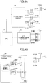
- Fig. 3 is an example of a block diagram illustrating a control apparatus according to an embodiment of the present invention. It should be noted that a section surrounded by a one-dot chain line in Fig. 3 indicates a part related to an APC control.
- a laser module 21 includes lasers 211R, 211G, and 211B, which emit laser beams having light amounts corresponding to a current value, and a light amount detection sensor 215 that monitors the immediate light amount of each of the lasers 211R, 211G, and 211B.
- the laser 211R is, for example, a red semiconductor laser, and is capable of emitting light with a wavelength ⁇ R (e.g., 640 nm).
- the laser 211G is, for example, a green semiconductor laser, and is capable of emitting light with a wavelength ⁇ G (e.g., 530 nm).
- the laser 211B is, for example, a blue semiconductor laser, and is capable of emitting light with a wavelength ⁇ B (e.g., 445 nm).
- the light amount detection sensor 2115 for example, a photodiode, etc., may be used.
- the light amount detection sensor 215 may be arranged at any position as long as it can detect the laser beam amount before entering the optical scanning unit 15.
- the system controller 23 is capable of, for example, controlling a swing angle of the mirror (not shown) of the optical scanning unit 15.
- the system controller 23 is capable of monitoring, for example, a tilt of the mirror in the horizontal direction and vertical direction obtained by a horizontal displacement sensor (not shown) and a vertical displacement sensor (not shown), included in the optical scanning unit 15, via a buffer circuit 24, and is capable of providing an angle control signal to a mirror drive circuit 25. Further, based on the angle control signal from the system controller 23, the mirror drive circuit 25 is capable of driving (for scanning the beam) the mirror of the optical scanning unit 15 for a predetermined angle.
- the system controller 23 is capable of providing, to the laser drive circuit 26, a drive signal corresponding to a digital video signal that is input from outside the control apparatus 20.
- outside the control apparatus 20 refers to, for example, a personal computer, a camera module, etc.
- the laser drive circuit 26 supplies predetermined electric currents to the lasers 211R, 211G, and 211B of the laser module 21 based on the drive signal from the system controller 23. According to the above operations, it is possible for the lasers 211R, 211G, and 211B to emit red light, green light, and blue light, respectively, whose light amounts are controlled based on the video signal, and it is possible to generate a color image, corresponding to the digital video signal that is input from outside the control apparatus 20, by mixing the red light, green light, and blue light.
- a CPU 27 is capable of providing a light amount control signal to the laser module 21 by, for example, monitoring originally emitted light amounts of the lasers 211R, 211G, and 211B based on a signal obtained by converting a current output of the light amount detection sensor 215 into a voltage by using an I/V conversion circuit 28. Electric currents to the lasers 211R, 211G, and 211B are controlled based on the light amount control signal from the CPU 27 so as to achieve predetermined outputs (light amounts).
- the predetermined outputs are target light amounts that are determined based on the light amount of external light detected by the light amount detection sensor 215, and an amount deviated from the determined target light amount is feedback-controlled based on the output of the light amount detection sensor 215.
- the light amount detection sensor 215 may include three sensors that independently detect the light amounts emitted from the corresponding lasers 211R, 211G, and 211B.
- the light amount detection sensor 215 may include only a single sensor. In this case, it is possible to control the light amounts emitted from the lasers 211R, 211G, and 211B by causing the lasers 211R, 211G, and 211B to sequentially emit light and by sequentially detecting the light amounts with the single sensor.
- the laser beams having corresponding wavelengths emitted from the lasers 211R, 211G, and 211B are mixed by a dichroic mirror, etc.
- the mixed result is emitted onto the mirror of the optical scanning unit 15 of the attachment unit 10 via an optical fiber (not shown) in the transmission cable 30, and the light is scanned by the mirror.
- the laser beam, which has been scanned by the mirror of the optical scanning unit 15, is used for directly projecting a video image on the retinal of the user of the attachment unit 10 via the projection optical system 16, and it is possible for the user to view the video image with a predetermined brightness.
- the CPU 27 is connected to the system controller 23, the buffer circuit 24, the mirror drive circuit 25, and the laser drive circuit 26, and it is specified that the initial settings of the system controller 23, the buffer circuit 24, the mirror drive circuit 25, and the laser drive circuit 26 (settings of output voltage value range, etc.,) are performed by the CPU 27.
- Figs. 4A and 4B are drawings illustrating an APC control according to an embodiment of the present invention.
- Fig. 4A is a block diagram illustrating the portion surrounded by the one-dot chain line in Fig. 3 in detail.
- Fig. 4B is a block diagram illustrating the inside of the laser drive circuit 26 in a simple manner.
- Fig. 5 is an example of I-L characteristics of a laser.
- the laser 211R, the laser 211 G, and the laser 211B that are used in the display apparatus 1 are low output lasers.
- the low output laser is a laser whose emission power is less than that of a laser with a typical output (emission power is about several ten mW).
- a laser, whose maximum emission power is equal to or less than 10 mW is referred to as a low output laser.
- a standard output laser there is a case in which a laser with a typical output, whose emission power is about several tens mW.
- An operational current of the low output laser is less than that of the standard output laser, and is, for example, about a fifth of the operational current of the standard output laser.
- an anode side of each of the lasers 211R, laser 211G, and the laser 211B is connected to a laser power supply VLD, and each cathode side is connected to the laser drive circuit 26.
- a resistor 212R is connected in parallel with the laser 211R.
- a resistor 212G is connected in parallel with the laser 211G, and a resistor 212B is connected in parallel with the laser 211B.
- the resistors 212R, 212G, and 212B are representative examples of a shunting element according to an embodiment of the present invention.
- the laser drive circuit 26 has a function of supplying currents to the lasers 211R, 211G, and 211B, and the resistors 212R, 212G, and 212B.
- the laser drive circuit 26 is not a dedicated drive circuit that is dedicatedly (exclusively) designed for a low output laser, but is a drive circuit designed for the standard output laser. Therefore, the laser drive circuit 26 is designed in such a way that the current value can be adjusted on a discrete basis in an operational current range that is higher than an operational current of the low output laser (i.e., in an operational current range for the standard output laser).
- the light amount detection sensor 215 includes sensors 215R, 215G, and 215B for independently detecting the light amounts emitted from the lasers 211R, 211G, and 211B.
- the sensors 215R, 215G, and 215B are, for example, photodiodes.
- the laser drive circuit 26 includes a VIDEO DAC A 262, a current source 263, a VIDEO DAC B 264, and a current source 265 for generating currents representing video images.
- the VIDEO DAC A 262 and the current source 263 supply a current in an I gain region in the I-L characteristics in Fig. 5 to a laser
- the VIDEO DAC B 264 and the current source 265 supply a current in an I th region in the I-L characteristics illustrated in Fig. 5 .
- a VIDEO SIGNAL 261 allocates video data input from the system controller 23 to the I gain region and the I th region, and provides the allocated video data to the VIDEO DAC A262 and the VIDEO DAC B 264. It should be noted that the circuit illustrated in Fig. 4B is provided with respect to each of the lasers 211R, 211G, and 211B.
- a maximum adjustment value of the VIDEO DAC A 262 is 320 mA
- a maximum adjustment value of the VIDEO DAC B 264 is 80 mA
- the video signal has 256 tones
- the resolution of the VIDEO DAC A 262 is 1.25 mA
- the resolution of the VIDEO DAC B 264 is 0.313 mA.
- Fig. 6 is an example of a flowchart of the APC control.
- the light amount detection sensor 215 obtains a light amount of each tone as a current value.
- the I/V conversion circuit 28 converts the current value obtained by the light amount detection sensor 215 to a voltage value that can be processed by the CPU 27, and provides the converted voltage value to the CPU 27.
- step S103 the CPU 27 calculates a target value of the light amount of each laser and a control amount.
- step S104 and step S105 the laser drive circuit 26 controls each laser in such a way that each laser emits light with the adjusted light amount based on the target value and the control amount calculated by the CPU 27.
- an I gain region control is performed by the VIDEO DAC A 262 and the current source 263
- an I th region control is performed by the VIDEO DAC B 264 and the current source 265.
- I out (xxh/FFh)* (yyh/FFh)*a.
- (xxh/FFh) is the video data (color tone)
- (yyh/FFh)” is laser current gain register setting
- "a” is a maximum adjustment value (rated current) of each of the VIDEO DACs of the laser drive circuit 26.
- Fig. 7A illustrates the relationship between the video data and I out in the case where a resistor 212 R equivalent to the laser 211R is not connected in parallel with the laser 211R.
- Fig. 7B illustrates the relationship between the video data and I out in the case where a resistor 212 R equivalent to the laser 211R is connected in parallel with the laser 211R.
- the resolution of the register setting is improved when a resistor 212R is connected in parallel with the laser 211R.
- the resolution of the register setting is doubled. It is possible to improve the resolution of the register setting to a predetermined value by adjusting the value of the resistor 212R.
- the method of calculating the resistor 212R that is connected in parallel with the laser 211R is the same as the method of calculating the resistor 212G that is connected in parallel with the laser 211G, and is the same as the method of calculating the resistor 212B that is connected in parallel with the laser 211B. Therefore, here, as illustrated in Fig. 8 , the method of calculating a resistor 212R in the case where the resistor 212R that is connected in parallel with the laser 211R will be described.
- I out is a current supplied from a laser power supply VLD
- i 1 is a current that flows through the laser 211R
- i 2 is a current that flows through the resistor 212R
- VI is a voltage across the laser 211R
- V2 is a voltage across the resistor 212R.
- the I-V characteristics of the laser 211R are, for example, as shown in Fig. 9 , which is referred to as a function f i (V).
- I out 2fi(V).
- Fig. 8 compared with the circuit of a comparative example illustrated in Fig. 10 , when outputting the same power P, the I out is doubled as illustrated in Fig. 11 .
- Fig. 11 compared with a case without a resistor, the I th region in a case with a resistor is doubled, and the inclination (slope) of the I-L characteristics in the I gain region is 1/2.
- a maximum adjustment value of the VIDEO DAC A 262 is 320 mA
- a maximum adjustment value of the VIDEO DAC B 264 is 80 mA
- the video signal has 256 tones
- the resolution of the VIDEO DAC A 262 is 1.25 mA
- the resolution of the VIDEO DAC B 264 is 0.313 mA.
- I th , I op , and a resolution per level, in a case of a conventional circuit of the comparative example illustrated in Fig. 10 are illustrated in Table 2. It should be noted that “I th “ illustrated in Table 2 is a current at which each of the lasers starts oscillation, and “I op " is an operational current at the time of a standard output of each of the lasers. “I op " belongs to the I gain region.
- Table 2 in order to compare with a case of a laser with a typical output (i.e., standard output laser), example values of a case of a laser with a typical output are also illustrated.
- Table 2 in case of the conventional circuit of the comparative example illustrated in Fig. 10 , when a laser with a typical output is compared with a low output laser for each color, the resolution with a low output laser is five times rougher than the resolution with a laser with a typical output.
- the resolution per level is a resolution of the register setting in a case where a resistor is not connected in parallel with the laser (i.e., the value illustrated in Table 2). It is known from Table 2 that the resolution of register setting for each color is doubled by connecting a resistor in parallel with the laser. It is also possible to increase the resolution of register setting further by changing the ratio between i 1 and i 2 by adjusting the value of the resistor that is connected in parallel with the laser.
- a semiconductor laser is characterized in that the characteristics change according to external factors such as the temperature.
- the change of the characteristics has a big impact on the color tone of the video to be projected. Therefore, in the video projection method that uses a laser as a light source, it is necessary to control the light amount according to the characteristics change. This control is automatically provided by the automatic power control (APC) of the white balance.
- APC automatic power control
- the accuracy of the white balance APC adjustment is improved. According to the above, compared with the conventional technique, it is possible to maintain the quality of video image without causing the quality to be degraded from the conventional quality. In other words, it is possible to cause the adjustment width of the laser current to be finer (smaller) by increasing the resolution of register setting by connecting a resistor in parallel with the laser, and thus, it is possible to increase the accuracy of the white balance APC adjustment.
- Fig. 12A and Fig. 12B are drawings illustrating the white balance adjustment.
- Fig. 12A illustrates a case in which the resolution of the register setting is low and the adjustment width of the laser current is rough (large) (a case of Fig. 10 ).
- Fig. 12B illustrates a case in which the resolution of the register setting is high and the adjustment width of the laser current is fine (small) (a case of Fig. 8 ).
- pictures next to each other indicate a case in which the laser current is changed by one adjustment width.
- the adjustment width is not sufficient (is too large) (in this example, there are only three adjustable current levels), and, when the laser current is changed by one adjustment width, the brightness changes greatly. In particular, it is difficult to control the white balance with the low output laser whose I gain region is small.
- the adjustment width is sufficient (is small enough) (in this example, there are six adjustable current levels), and, when the laser current is changed by one adjustment width, the brightness changes slightly. According to the above, it becomes easy to control the white balance with the low output laser whose I gain region is small.
- the fineness of the adjustment width of the laser current is related to the adjustment accuracy of the brightness (white balance) of the video image projected by the display apparatus 1. Further, it becomes possible to improve the adjustment resolution of the current value of the laser current by increasing the resolution of register setting by connecting a resistor in parallel with the laser, and thus, it is possible to increase the white balance APC adjustment accuracy. As a result, in a display apparatus 1 in which the low output laser is driven by a drive circuit for the standard output laser, it becomes possible to project a video image with a stable image quality and without depending on the temperature change.
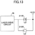
- a shunting element other than a resistor, is connected in parallel with the laser. It should be noted that, in the modified example of the first embodiment, descriptions related to the same structure as the first embodiment may be omitted.
- Fig. 13 is a drawing illustrating an example in which a shunting element, other than a resistor, is connected in parallel with the laser.
- a shunting element other than a resistor
- a laser 219R is connected in parallel with the laser 211R.
- the similar circuits are used for the lasers 211G and 211B (drawings are omitted).
- a diode other than a laser instead of the laser 219R, a diode other than a laser, a variable resistor, etc., may be used.
- a variable resistor it is possible to cause the resolution of the register setting to be variable, which is preferable,
- the CPU 27 may adjust the setting of the variable resistor (resistance value).
Abstract
Description
- The present invention relates to a display apparatus.
- In a display apparatus that is used for causing a user to view a predetermined video, there is a case in which a semiconductor laser is used as a light source. In general, characteristics of a semiconductor laser vary greatly according to temperature and the emission power may change even when the semiconductor laser is driven by the same electric current value. Therefore, an APC (Auto Power Control) is used that maintains the emission power at a constant level (refer to, e.g., Patent Document 1).
- In general, in a display apparatus as described above, a laser is used whose emission power is about several ten mW, and the laser is driven by a dedicated drive circuit that is capable of adjusting the electric current value on a discrete basis in the whole range of the operational current corresponding to the emission power.
- [Patent Document 1] Japanese Unexamined Patent Application Publication No.
2001-257420 - Here, as such a display apparatus that is used for causing a user to view a predetermined video, there is a retinal scanning type display apparatus that is attached to the user's head, and that is used for causing the user to view an image by directly scanning the light on the retinal of the user to form an image. In the retinal scanning type display apparatus, taking safety into consideration, there is a case in which a low output laser (whose emission power is equal to or less than about 10 mW) is used, whose emission power is less than that of a typical laser (whose emission power is about 10 mW).
- Because of the fact that a dedicated drive IC that is dedicated to drive a low output laser does not exist at the moment, even in the case of using a low output laser, it is assumed that the low output laser is used still in combination with a drive IC that is used for a laser with a typical output. However, the operational current of a low output laser is about a fifth of the operational current of a laser with a typical output. Therefore, when the low output laser is used in combination with a drive IC that is used for a laser with a typical output, only adjustable current values on the low current side, which is only a part of the whole range, can be used. Therefore, there is a problem that the sufficient current value adjustment resolution cannot be obtained.
- In view of the above, the present invention has been made. An object of the present invention is to improve the current value adjustment resolution in the case where a low output laser, which is mounted on a retinal scanning type display apparatus, is driven by not using a dedicated drive IC.
- A display apparatus (1) is provided. The display apparatus (1) is a retinal scanning type display apparatus (1), and includes a low output laser (211R) whose operational current is less than that of a standard output laser; a shunting element (212R) that is connected in parallel with the low output laser (211R); and a drive circuit (26) that supplies a current to the low output laser (211R) and the shunting element (212R), wherein the drive circuit (26) is a drive circuit for the standard output laser capable of adjusting the current value on a discrete basis in a range of the operational current that is higher than the operational current of the low output laser (211R).
- It should be noted that reference numerals in the above parentheses are provided in order to facilitate easy understanding, are just examples, and are not limited to aspects illustrated in the drawings.
- According to an embodiment of the present invention, it is possible to improve the current value adjustment resolution in the case where a low output laser mounted on a retinal scanning type display apparatus is driven by not using a dedicated drive IC.
-
-
Fig. 1 is a perspective view illustrating an example of an appearance of a display apparatus according to an embodiment of the present invention. -
Fig. 2 is a schematic diagram illustrating an example of a projection optical system of a display apparatus according to an embodiment of the present invention. -
Fig. 3 is an example of a block diagram illustrating a control apparatus according to an embodiment of the present invention. -
Figs. 4A and 4B are drawings illustrating an APC control according to an embodiment of the present invention. -
Fig. 5 is an example of I-L characteristics of a laser. -
Fig. 6 is an example of a flowchart of the APC control. -
Figs. 7A and 7B are drawings illustrating resolution improvement of register setting. -
Fig. 8 is a drawing illustrating a method of calculating a resistor (resistance) that is connected in parallel with a laser. -
Fig. 9 is an example of I-L characteristics of a laser. -
Fig. 10 is a conventional circuit as a comparative example. -
Fig. 11 is a drawing illustrating comparison of I-L characteristics between a case with a resistor and a case without a resistor. -
Figs. 12A and 12B are drawings illustrating white balance adjustment. -
Fig. 13 is a drawing illustrating an example in which a shunting element, other than the resistor, is connected in parallel with a laser. - In the following, embodiments of the present invention will be described while making reference to the drawings. Throughout the drawings, a same reference numeral is given to a same element, and duplicated descriptions may be omitted.
-
Fig. 1 is a perspective view illustrating an example of an appearance of adisplay apparatus 1 according to an embodiment of the present invention.Fig. 2 is a schematic diagram illustrating an example of a projection optical system of adisplay apparatus 1 according to an embodiment of the present invention. - The
display apparatus 1 illustrated inFig. 1 andFig. 2 is a retinal scanning type head-mount display that directly projects an image on the retinal of an eye of the user. - The
display apparatus 1 can be used, for example, as an apparatus for causing a user to view information for work assistance, which has been recorded beforehand in a database, etc. Alternatively, a camera module may be included in thedisplay apparatus 1, and thedisplay apparatus 1 may be used as an apparatus for causing a user to view information obtained by the camera module. Alternatively, thedisplay apparatus 1 may be an apparatus that has functions of both of the above-described apparatuses. - The
display apparatus 1 includes, as main elements, anattachment unit 10 that can be attached to the head of a user (a person to whom thedisplay apparatus 1 is attached), and acontrol box 20B in which a control apparatus 20 (described below) that controls theattachment unit 10 is built (included). Thecontrol box 20B is, for example, a rectangular housing, and may include various types of switches, a display unit, etc., if necessary. Theattachment unit 10 is connected to thecontrol apparatus 20 in thecontrol box 20B via atransmission cable 30 that includes an optical fiber or an electric wire. - According to an embodiment of the present invention, the
attachment unit 10 is, as an example, an eyeglass type, which includes two sets of afront part 10f and a side (temple)part 10t, the sets being provided substantially symmetrically on the left and right. Thefront part 10f includes a lens (including a lens without optical correction). - In one of the
temple parts 10t on the left and right (thetemple part 10t on the left eye side inFig. 1 ), anoptical scanning unit 15 and a projectionoptical system 16 including alens 161 and ahalf mirror 162 illustrated inFig. 2 are installed. In other words, in thedisplay apparatus 1, theoptical scanning unit 15 and the projectionoptical system 16 are installed only in atemple part 10t on one eye side. Theoptical scanning unit 15 and the projectionoptical system 16 may be arranged on the right eye side or the left eye side, and have a function of projecting a video on the retinal of the eye on whose side theoptical scanning unit 15 and the projectionoptical system 16 are arranged. - The
optical scanning unit 15 scans an incident laser beam in two dimensions. The scanned laser beam is used for projecting a two-dimensional video image directly on the retinal of aneyeball 500 of the user of thedisplay apparatus 1 via thelens 161 and thehalf mirror 162. - The
optical scanning unit 15 includes, for example, a mirror that swings (vibrates) with respect to two axes orthogonal to each other. Theoptical scanning unit 15 may be, for example, a MEMS (Micro Electro Mechanical Systems) made by a semiconductor process, etc. The mirror of theoptical scanning unit 15 may be driven by, for example, an actuator that uses deforming forces of piezoelectric elements as drive forces. It should be noted that the projectionoptical system 16 may include optical parts, etc., other than thelens 161 and thehalf mirror 162. -
Fig. 3 is an example of a block diagram illustrating a control apparatus according to an embodiment of the present invention. It should be noted that a section surrounded by a one-dot chain line inFig. 3 indicates a part related to an APC control. - As illustrated in
Fig. 3 , in thecontrol apparatus 20, alaser module 21 includeslasers amount detection sensor 215 that monitors the immediate light amount of each of thelasers - The
laser 211R is, for example, a red semiconductor laser, and is capable of emitting light with a wavelength λR (e.g., 640 nm). Thelaser 211G is, for example, a green semiconductor laser, and is capable of emitting light with a wavelength λG (e.g., 530 nm). Thelaser 211B is, for example, a blue semiconductor laser, and is capable of emitting light with a wavelength λB (e.g., 445 nm). - As the light
amount detection sensor 215, for example, a photodiode, etc., may be used. The lightamount detection sensor 215 may be arranged at any position as long as it can detect the laser beam amount before entering theoptical scanning unit 15. - The
system controller 23 is capable of, for example, controlling a swing angle of the mirror (not shown) of theoptical scanning unit 15. Thesystem controller 23 is capable of monitoring, for example, a tilt of the mirror in the horizontal direction and vertical direction obtained by a horizontal displacement sensor (not shown) and a vertical displacement sensor (not shown), included in theoptical scanning unit 15, via abuffer circuit 24, and is capable of providing an angle control signal to amirror drive circuit 25. Further, based on the angle control signal from thesystem controller 23, themirror drive circuit 25 is capable of driving (for scanning the beam) the mirror of theoptical scanning unit 15 for a predetermined angle. - Further, for example, the
system controller 23 is capable of providing, to thelaser drive circuit 26, a drive signal corresponding to a digital video signal that is input from outside thecontrol apparatus 20. It should be noted that "outside thecontrol apparatus 20" refers to, for example, a personal computer, a camera module, etc. - The
laser drive circuit 26 supplies predetermined electric currents to thelasers laser module 21 based on the drive signal from thesystem controller 23. According to the above operations, it is possible for thelasers control apparatus 20, by mixing the red light, green light, and blue light. - Further, a
CPU 27 is capable of providing a light amount control signal to thelaser module 21 by, for example, monitoring originally emitted light amounts of thelasers amount detection sensor 215 into a voltage by using an I/V conversion circuit 28. Electric currents to thelasers CPU 27 so as to achieve predetermined outputs (light amounts). Here, the predetermined outputs are target light amounts that are determined based on the light amount of external light detected by the lightamount detection sensor 215, and an amount deviated from the determined target light amount is feedback-controlled based on the output of the lightamount detection sensor 215. - It should be noted that the light
amount detection sensor 215 may include three sensors that independently detect the light amounts emitted from the correspondinglasers amount detection sensor 215 may include only a single sensor. In this case, it is possible to control the light amounts emitted from thelasers lasers - The laser beams having corresponding wavelengths emitted from the
lasers optical scanning unit 15 of theattachment unit 10 via an optical fiber (not shown) in thetransmission cable 30, and the light is scanned by the mirror. The laser beam, which has been scanned by the mirror of theoptical scanning unit 15, is used for directly projecting a video image on the retinal of the user of theattachment unit 10 via the projectionoptical system 16, and it is possible for the user to view the video image with a predetermined brightness. - It should be noted that some of the arrows are omitted in
Fig. 3 . TheCPU 27 is connected to thesystem controller 23, thebuffer circuit 24, themirror drive circuit 25, and thelaser drive circuit 26, and it is specified that the initial settings of thesystem controller 23, thebuffer circuit 24, themirror drive circuit 25, and the laser drive circuit 26 (settings of output voltage value range, etc.,) are performed by theCPU 27. -
Figs. 4A and 4B are drawings illustrating an APC control according to an embodiment of the present invention.Fig. 4A is a block diagram illustrating the portion surrounded by the one-dot chain line inFig. 3 in detail.Fig. 4B is a block diagram illustrating the inside of thelaser drive circuit 26 in a simple manner.Fig. 5 is an example of I-L characteristics of a laser. - The
laser 211R, thelaser 211 G, and thelaser 211B that are used in thedisplay apparatus 1 are low output lasers. The low output laser is a laser whose emission power is less than that of a laser with a typical output (emission power is about several ten mW). In the present specification, a laser, whose maximum emission power is equal to or less than 10 mW, is referred to as a low output laser. Further, there is a case in which a laser with a typical output, whose emission power is about several tens mW, is referred to as a standard output laser. - An operational current of the low output laser is less than that of the standard output laser, and is, for example, about a fifth of the operational current of the standard output laser.
- As illustrated in
Fig. 4A , an anode side of each of thelasers 211R,laser 211G, and thelaser 211B is connected to a laser power supply VLD, and each cathode side is connected to thelaser drive circuit 26. Further, aresistor 212R is connected in parallel with thelaser 211R. Similarly, aresistor 212G is connected in parallel with thelaser 211G, and aresistor 212B is connected in parallel with thelaser 211B. Theresistors - The
laser drive circuit 26 has a function of supplying currents to thelasers resistors laser drive circuit 26 is not a dedicated drive circuit that is dedicatedly (exclusively) designed for a low output laser, but is a drive circuit designed for the standard output laser. Therefore, thelaser drive circuit 26 is designed in such a way that the current value can be adjusted on a discrete basis in an operational current range that is higher than an operational current of the low output laser (i.e., in an operational current range for the standard output laser). - The light
amount detection sensor 215 includessensors lasers sensors - As illustrated in
Fig. 4B , thelaser drive circuit 26 includes aVIDEO DAC A 262, acurrent source 263, aVIDEO DAC B 264, and acurrent source 265 for generating currents representing video images. TheVIDEO DAC A 262 and thecurrent source 263 supply a current in an Igain region in the I-L characteristics inFig. 5 to a laser, and theVIDEO DAC B 264 and thecurrent source 265 supply a current in an Ith region in the I-L characteristics illustrated inFig. 5 . - A
VIDEO SIGNAL 261 allocates video data input from thesystem controller 23 to the Igain region and the Ith region, and provides the allocated video data to the VIDEO DAC A262 and theVIDEO DAC B 264. It should be noted that the circuit illustrated inFig. 4B is provided with respect to each of thelasers - For example, when a maximum adjustment value of the
VIDEO DAC A 262 is 320 mA, a maximum adjustment value of theVIDEO DAC B 264 is 80 mA, and the video signal has 256 tones, the resolution of theVIDEO DAC A 262 is 1.25 mA, and the resolution of theVIDEO DAC B 264 is 0.313 mA. -
Fig. 6 is an example of a flowchart of the APC control. First, in step S101, the lightamount detection sensor 215 obtains a light amount of each tone as a current value. Next, in step S102, the I/V conversion circuit 28 converts the current value obtained by the lightamount detection sensor 215 to a voltage value that can be processed by theCPU 27, and provides the converted voltage value to theCPU 27. - Next, in step S103, the
CPU 27 calculates a target value of the light amount of each laser and a control amount. - Next, in step S104 and step S105, the
laser drive circuit 26 controls each laser in such a way that each laser emits light with the adjusted light amount based on the target value and the control amount calculated by theCPU 27. At this time, an Igain region control is performed by theVIDEO DAC A 262 and thecurrent source 263, and an Ith region control is performed by theVIDEO DAC B 264 and thecurrent source 265. - The calculation of the control amount will be described below. An Iout in
Figs. 4A and 4B can be calculated according to Iout= (xxh/FFh)* (yyh/FFh)*a. Here, "(xxh/FFh)" is the video data (color tone), "(yyh/FFh)" is laser current gain register setting, and "a" is a maximum adjustment value (rated current) of each of the VIDEO DACs of thelaser drive circuit 26. - The relationship between the gain register value and Iout changes according to whether or not a
resistor 212 R equivalent to thelaser 211R is connected in parallel with thelaser 211R.Fig. 7A illustrates the relationship between the video data and Iout in the case where aresistor 212 R equivalent to thelaser 211R is not connected in parallel with thelaser 211R.Fig. 7B illustrates the relationship between the video data and Iout in the case where aresistor 212 R equivalent to thelaser 211R is connected in parallel with thelaser 211R. - In either case of
Fig. 7A or Fig. 7B , when the gain register setting is changed, the inclination (slope) with respect to the video data is changed. However, in the case where aresistor 212 R equivalent to thelaser 211R is connected in parallel with thelaser 211R, as illustrated inFig. 7B , it is possible to cause the set gain value to be half. In other words, when the same gain register setting is applied to the same video data, an obtained Iout inFig. 7B is a half of the Iout inFig. 7A . - This means that the resolution of the register setting is improved when a
resistor 212R is connected in parallel with thelaser 211R. In the case where aresistor 212 R equivalent to thelaser 211R is connected in parallel with thelaser 211R, the resolution of the register setting is doubled. It is possible to improve the resolution of the register setting to a predetermined value by adjusting the value of theresistor 212R. - Next, a method of calculating the value of the resistor that is connected in parallel with each laser will be described. The method of calculating the
resistor 212R that is connected in parallel with thelaser 211R is the same as the method of calculating theresistor 212G that is connected in parallel with thelaser 211G, and is the same as the method of calculating theresistor 212B that is connected in parallel with thelaser 211B. Therefore, here, as illustrated inFig. 8 , the method of calculating aresistor 212R in the case where theresistor 212R that is connected in parallel with thelaser 211R will be described. - In
Fig. 8 , "Iout" is a current supplied from a laser power supply VLD, "i1" is a current that flows through thelaser 211R, "i2" is a current that flows through theresistor 212R, "VI" is a voltage across thelaser 211R, and "V2" is a voltage across theresistor 212R. - In
Fig. 8 , Iout=i1+i2, and V=V1=V2. Therefore, when the resistance value of theresistor 212R is referred to as "R", i2=V/R. - Further, the I-V characteristics of the
laser 211R are, for example, as shown inFig. 9 , which is referred to as a function fi(V). A unique "I" can be obtained from a given "V" according to fi(V). Therefore, i1=fi(V). Considering the fact that Iout=i1+i2 and i2=V/R, the followingformula 1 is obtained. Iout=fi(V)+V/R ... (formula 1) - Here, a case is considered in which the resolution is doubled. In this case, ii=i2.
Iout=i1+i2=V/R+V/R=2V/R. According to the above, together with theformula 1, an equation fi(V)=V/R is obtained. By transforming the equation, the followingformula 2 can be derived. R=V/fi(V) ... (formula 2) According to theformula 2, the value of a resistor that is connected in parallel with each color of the lasers, and that is used for doubling the resolution, is shown in Table 1. As illustrated in Table 1, resistors with different resistance values are connected in parallel with the corresponding lasers having different emission wavelengths (having different colors).[Table 1] LOW OUTPUT LD i2 [mA] fi (V) [V] R [Ω] RED 35 2.28 65 GREEN 40 5.02 126 BLUE 20 4.24 212 - Here, as a comparative example, a case will be considered (described) in which the
resistor 212R is not connected in parallel with thelaser 211R. As illustrated inFig. 10 , in the case where theresistor 212R is not connected in parallel with thelaser 211R,
Iout=i1, and V=V1. Therefore, according to theformula 1, Iout=fi (V) . - On the other hand, in the case where the
resistor 212R is connected in parallel with thelaser 211R, according to theformula 1 and theformula 2, Iout=2fi(V). The above descriptions mean that, in the circuit illustrated inFig. 8 , compared with the circuit of a comparative example illustrated inFig. 10 , when outputting the same power P, the Iout is doubled as illustrated inFig. 11 . It should be noted that, inFig. 11 , compared with a case without a resistor, the Ith region in a case with a resistor is doubled, and the inclination (slope) of the I-L characteristics in the Igain region is 1/2. - Similar to the previous case, when a maximum adjustment value of the
VIDEO DAC A 262 is 320 mA, a maximum adjustment value of theVIDEO DAC B 264 is 80 mA, and the video signal has 256 tones, the resolution of theVIDEO DAC A 262 is 1.25 mA, and the resolution of theVIDEO DAC B 264 is 0.313 mA. - Ith, Iop, and a resolution per level, in a case of a conventional circuit of the comparative example illustrated in
Fig. 10 , are illustrated in Table 2. It should be noted that "Ith" illustrated in Table 2 is a current at which each of the lasers starts oscillation, and "Iop" is an operational current at the time of a standard output of each of the lasers. "Iop" belongs to the Igain region. - In Table 2, in order to compare with a case of a laser with a typical output (i.e., standard output laser), example values of a case of a laser with a typical output are also illustrated. According to Table 2, in case of the conventional circuit of the comparative example illustrated in
Fig. 10 , when a laser with a typical output is compared with a low output laser for each color, the resolution with a low output laser is five times rougher than the resolution with a laser with a typical output.[Table 2] Ith [mA] Iop [mA] RESOLUTION PER LEVEL (%) LD WITH TYPICAL OUTPUT RED 70 190 0.66 GREEN 40 220 0.57 BLUE 30 110 1.14 LOW OUTPUT LD RED 23 35 3.57 GREEN 28 40 3.13 BLUE 10 20 6.25 - Next, regarding the circuit illustrated in
Fig. 8 , the resolution for each color in the case where ii=i2 as shown in Table 1 will be calculated as follows. In case of red color, according to Table 1, i1=i2=35 mA. Therefore, Iout=i1+i2=70 mA. The resolution 1.25 mA of theVIDEO DAC A 262 is translated as an adjustment width (a unit of adjustment) 1.79% for 70 mA. Similarly, calculation results of resolutions (adjustment widths) in case of green color and blue color are illustrated in Table 3.[Table 3] Ith [mA] Iop [mA] RESOLUTION PER LEVEL (%) RESOLUTION AFTER RESISTOR CONNECTION (%) RED 23 35 3.57 1.79 GREEN 28 40 3.13 1.56 BLUE 10 20 6.25 3.13 - In Table 3, the resolution per level is a resolution of the register setting in a case where a resistor is not connected in parallel with the laser (i.e., the value illustrated in Table 2). It is known from Table 2 that the resolution of register setting for each color is doubled by connecting a resistor in parallel with the laser. It is also possible to increase the resolution of register setting further by changing the ratio between i1 and i2 by adjusting the value of the resistor that is connected in parallel with the laser.
- A semiconductor laser is characterized in that the characteristics change according to external factors such as the temperature. The change of the characteristics has a big impact on the color tone of the video to be projected. Therefore, in the video projection method that uses a laser as a light source, it is necessary to control the light amount according to the characteristics change. This control is automatically provided by the automatic power control (APC) of the white balance.
- As described above, when the resolution of the register setting is improved, the accuracy of the white balance APC adjustment is improved. According to the above, compared with the conventional technique, it is possible to maintain the quality of video image without causing the quality to be degraded from the conventional quality. In other words, it is possible to cause the adjustment width of the laser current to be finer (smaller) by increasing the resolution of register setting by connecting a resistor in parallel with the laser, and thus, it is possible to increase the accuracy of the white balance APC adjustment.
-
Fig. 12A and Fig. 12B are drawings illustrating the white balance adjustment.Fig. 12A illustrates a case in which the resolution of the register setting is low and the adjustment width of the laser current is rough (large) (a case ofFig. 10 ).Fig. 12B illustrates a case in which the resolution of the register setting is high and the adjustment width of the laser current is fine (small) (a case ofFig. 8 ). Further, inFig. 12A and Fig. 12B , pictures next to each other indicate a case in which the laser current is changed by one adjustment width. - As illustrated in
Fig. 12A , in the case where the resolution of register setting is low and the adjustment width of the laser current is coarse, the adjustment width is not sufficient (is too large) (in this example, there are only three adjustable current levels), and, when the laser current is changed by one adjustment width, the brightness changes greatly. In particular, it is difficult to control the white balance with the low output laser whose Igain region is small. - On the other hand, as illustrated in
Fig. 12B , in the case where the resolution of register setting is high and the adjustment width of the laser current is fine, the adjustment width is sufficient (is small enough) (in this example, there are six adjustable current levels), and, when the laser current is changed by one adjustment width, the brightness changes slightly. According to the above, it becomes easy to control the white balance with the low output laser whose Igain region is small. - As described above, the fineness of the adjustment width of the laser current is related to the adjustment accuracy of the brightness (white balance) of the video image projected by the
display apparatus 1. Further, it becomes possible to improve the adjustment resolution of the current value of the laser current by increasing the resolution of register setting by connecting a resistor in parallel with the laser, and thus, it is possible to increase the white balance APC adjustment accuracy. As a result, in adisplay apparatus 1 in which the low output laser is driven by a drive circuit for the standard output laser, it becomes possible to project a video image with a stable image quality and without depending on the temperature change. - In a modified example of the first embodiment, an example is shown in which a shunting element, other than a resistor, is connected in parallel with the laser. It should be noted that, in the modified example of the first embodiment, descriptions related to the same structure as the first embodiment may be omitted.
-
Fig. 13 is a drawing illustrating an example in which a shunting element, other than a resistor, is connected in parallel with the laser. In a circuit illustrated inFig. 13 , alaser 219R is connected in parallel with thelaser 211R. The similar circuits are used for thelasers - In the circuit illustrated in
Fig. 13 , it is possible to cause the currents that respectively flow through thelaser 211R and thelaser 219R to be substantially the same by using, as thelaser 219R, a laser that has the same specification as thelaser 211R. Therefore, similar to the case in which theresistor 212R that is equivalent to thelaser 211R is connected in parallel with thelaser 211R, it is possible to cause the set gain value to be half. - According to the above, similar to the first embodiment, it becomes possible to improve the adjustment resolution of the current value of the laser current, and it becomes possible to increase the white balance APC adjustment accuracy. As a result, in a
display apparatus 1 in which the low output laser is driven by a drive circuit for the standard output laser, it becomes possible to project a video image with a stable image quality and without depending on the temperature change. - Further, it is also possible to further increase the resolution of register setting by changing the ratio between i1 and i2 by connecting a laser with an appropriate specification in parallel with the
laser 211R. It should be noted that thelaser 219R is used for the current value adjustment, and is not intended to be used for forming an image. Therefore, it is necessary to provide measures for preventing the emitted light of thelaser 219R from affecting the images. - In the circuit in
Fig. 13 , instead of thelaser 219R, a diode other than a laser, a variable resistor, etc., may be used. In the case where a variable resistor is used, it is possible to cause the resolution of the register setting to be variable, which is preferable, TheCPU 27 may adjust the setting of the variable resistor (resistance value). - As described above, preferable embodiments have been described. However, the present invention is not limited to the above-described embodiments. Various modifications and replacements can be applied to the above-described embodiments without departing from the scope of the claims.
- The present application is based on and claims the benefit of priority of Japanese Priority Application No.
2017-069782 filed on March 31, 2017
Claims (5)
- A retinal scanning type display apparatus, the display apparatus comprising:a low output laser whose operational current is lower than a standard output laser;a shunting element that is connected in parallel with the low output laser; anda drive circuit that supplies a current to the low output laser and the shunting element, whereinthe drive circuit is a standard output laser drive circuit that is capable of adjusting a current value on a discrete basis in a range of an operational current higher than the operational current of the low output laser.
- The display apparatus according to claim 1, wherein
the low output laser includes a plurality of the low output lasers having different emission light wavelengths, and
the shunting elements having different characteristics are connected in parallel with the corresponding low output lasers. - The display apparatus according to claim 1, wherein
the shunting element is a resistor. - The display apparatus according to claim 2, wherein
the shunting elements having different characteristics are resistors having different resistance values. - The display apparatus according to any one of claims 1 to 4, wherein
the low output laser is a laser that is used with emission power equal to or less than 10 mW.
Applications Claiming Priority (1)
| Application Number | Priority Date | Filing Date | Title |
|---|---|---|---|
| JP2017069782A JP6853477B2 (en) | 2017-03-31 | 2017-03-31 | Display device |
Publications (1)
| Publication Number | Publication Date |
|---|---|
| EP3382442A1 true EP3382442A1 (en) | 2018-10-03 |
Family
ID=61768098
Family Applications (1)
| Application Number | Title | Priority Date | Filing Date |
|---|---|---|---|
| EP18163704.2A Withdrawn EP3382442A1 (en) | 2017-03-31 | 2018-03-23 | Display apparatus |
Country Status (4)
| Country | Link |
|---|---|
| US (1) | US10396526B2 (en) |
| EP (1) | EP3382442A1 (en) |
| JP (1) | JP6853477B2 (en) |
| CN (1) | CN108693649B (en) |
Cited By (1)
| Publication number | Priority date | Publication date | Assignee | Title |
|---|---|---|---|---|
| WO2020102132A1 (en) * | 2018-11-13 | 2020-05-22 | Facebook Technologies, Llc | Pupil steering: combiner actuation systems |
Families Citing this family (4)
| Publication number | Priority date | Publication date | Assignee | Title |
|---|---|---|---|---|
| WO2023067927A1 (en) * | 2021-10-18 | 2023-04-27 | 住友電気工業株式会社 | Light source module, glasses-like head-mounted display, and optical module |
| WO2023198607A1 (en) * | 2022-04-12 | 2023-10-19 | Ams Sensors Belgium Bvba | Laser circuit with two supply terminals and method for operating a laser circuit |
| WO2023198604A1 (en) * | 2022-04-12 | 2023-10-19 | Ams Sensors Belgium Bvba | Laser circuit with switched-capacitor circuit and method for operating a laser circuit |
| WO2023198606A1 (en) * | 2022-04-12 | 2023-10-19 | Ams Sensors Belgium Bvba | Laser circuit with two converters and method for operating a laser circuit |
Citations (5)
| Publication number | Priority date | Publication date | Assignee | Title |
|---|---|---|---|---|
| US4177436A (en) * | 1977-12-05 | 1979-12-04 | Bell Telephone Laboratories, Incorporated | Circuit for controlling the differential output power of a semiconductor laser |
| US5371755A (en) * | 1992-05-22 | 1994-12-06 | Hitachi, Ltd. | Optical transmission module |
| JP2001257420A (en) | 2000-03-09 | 2001-09-21 | Toshiba Tec Corp | Image forming apparatus and its control method |
| DE102009004117A1 (en) * | 2009-01-08 | 2010-07-15 | Osram Gesellschaft mit beschränkter Haftung | projection module |
| US20120188623A1 (en) * | 2011-01-24 | 2012-07-26 | Brother Kogyo Kabushiki Kaisha | Scanning image display device and method of controlling the same |
Family Cites Families (15)
| Publication number | Priority date | Publication date | Assignee | Title |
|---|---|---|---|---|
| JPH06151958A (en) * | 1992-11-02 | 1994-05-31 | Eastman Kodak Japan Kk | Light emitting device |
| US5920583A (en) * | 1994-02-22 | 1999-07-06 | Lucent Technologies Inc. | Dual laser with thermoelectric cooling |
| JP3632392B2 (en) * | 1997-08-14 | 2005-03-23 | 富士ゼロックス株式会社 | Retina display device |
| JP2001102680A (en) * | 1999-09-20 | 2001-04-13 | Lucent Technol Inc | Laser module and control module for laser |
| JP2003101127A (en) * | 2001-09-21 | 2003-04-04 | Hitachi Koki Co Ltd | Semiconductor laser driver |
| US7079460B2 (en) * | 2002-02-21 | 2006-07-18 | Mitsumi Electric Co., Ltd. | Optical power level-controlling device for stable oscillation of laser diode |
| JP2005032808A (en) * | 2003-07-08 | 2005-02-03 | Ntt Electornics Corp | Photoelectric conversion device |
| JP2005345748A (en) * | 2004-06-03 | 2005-12-15 | Brother Ind Ltd | Mirror driving apparatus and retina scanning display with same |
| US9083781B2 (en) * | 2004-11-15 | 2015-07-14 | Bascule Development Ag Llc | Portable image-capturing device with embedded projector |
| JP5316346B2 (en) * | 2009-09-30 | 2013-10-16 | ブラザー工業株式会社 | Retina scanning image display device |
| US9054488B2 (en) * | 2010-12-06 | 2015-06-09 | Maxim Integrated Products, Inc. | Speckle reduction for laser projection displays |
| US20140226688A1 (en) * | 2013-02-11 | 2014-08-14 | Raytheon Company | Multiple output diode driver with independent current control and output current modulation |
| JP2015031703A (en) * | 2013-07-31 | 2015-02-16 | セイコーエプソン株式会社 | Display device, head-mounted display device, display system, and control method of display device |
| JP2015103638A (en) * | 2013-11-25 | 2015-06-04 | セイコーエプソン株式会社 | Light-emitting device and image display device |
| JP2016004195A (en) * | 2014-06-18 | 2016-01-12 | 株式会社Jvcケンウッド | Light source drive device and image display device |
-
2017
- 2017-03-31 JP JP2017069782A patent/JP6853477B2/en active Active
-
2018
- 2018-03-13 US US15/919,420 patent/US10396526B2/en active Active
- 2018-03-23 EP EP18163704.2A patent/EP3382442A1/en not_active Withdrawn
- 2018-03-30 CN CN201810279431.4A patent/CN108693649B/en active Active
Patent Citations (5)
| Publication number | Priority date | Publication date | Assignee | Title |
|---|---|---|---|---|
| US4177436A (en) * | 1977-12-05 | 1979-12-04 | Bell Telephone Laboratories, Incorporated | Circuit for controlling the differential output power of a semiconductor laser |
| US5371755A (en) * | 1992-05-22 | 1994-12-06 | Hitachi, Ltd. | Optical transmission module |
| JP2001257420A (en) | 2000-03-09 | 2001-09-21 | Toshiba Tec Corp | Image forming apparatus and its control method |
| DE102009004117A1 (en) * | 2009-01-08 | 2010-07-15 | Osram Gesellschaft mit beschränkter Haftung | projection module |
| US20120188623A1 (en) * | 2011-01-24 | 2012-07-26 | Brother Kogyo Kabushiki Kaisha | Scanning image display device and method of controlling the same |
Cited By (2)
| Publication number | Priority date | Publication date | Assignee | Title |
|---|---|---|---|---|
| WO2020102132A1 (en) * | 2018-11-13 | 2020-05-22 | Facebook Technologies, Llc | Pupil steering: combiner actuation systems |
| EP3881124A1 (en) * | 2018-11-13 | 2021-09-22 | Facebook Technologies, LLC. | Pupil steering: combiner actuation systems |
Also Published As
| Publication number | Publication date |
|---|---|
| CN108693649B (en) | 2021-08-24 |
| JP2018173452A (en) | 2018-11-08 |
| US10396526B2 (en) | 2019-08-27 |
| CN108693649A (en) | 2018-10-23 |
| JP6853477B2 (en) | 2021-03-31 |
| US20180284442A1 (en) | 2018-10-04 |
Similar Documents
| Publication | Publication Date | Title |
|---|---|---|
| US10396526B2 (en) | Display apparatus | |
| US8164621B2 (en) | Image display device | |
| US20120188623A1 (en) | Scanning image display device and method of controlling the same | |
| US9462244B2 (en) | Image display apparatus and optical component | |
| JP5640420B2 (en) | Projection-type image display device | |
| JP5956949B2 (en) | Image display device | |
| US8767023B2 (en) | Scanning image display device and method of controlling the same | |
| US8540373B2 (en) | Retinal scanning display | |
| US11146764B2 (en) | Control device, optical scanning device, display apparatus, and control method | |
| WO2017183446A1 (en) | Display device | |
| CN110488488B (en) | Control device, optical scanning device, display device, and control method | |
| CA3044475A1 (en) | Speckle reduced laser projection with color gamut optimization | |
| US10523908B2 (en) | Light projection device | |
| JP2011075948A (en) | Image display | |
| US20090041488A1 (en) | Image forming apparatus and control method thereof | |
| JP2005242035A (en) | Picture projection device, and control method therefor | |
| JP2014059522A (en) | Image display device | |
| US20210176441A1 (en) | Display apparatus | |
| JP2019077100A (en) | Laser driving device, light source device, optical scanner, image forming device, image display device, and laser driving method | |
| CN110488487B (en) | Control device, optical scanning device, display device, and control method | |
| WO2016158098A1 (en) | Light scan control apparatus | |
| JP2017167197A (en) | Optical axis correction device, control method, program, and storage medium |
Legal Events
| Date | Code | Title | Description |
|---|---|---|---|
| PUAI | Public reference made under article 153(3) epc to a published international application that has entered the european phase |
Free format text: ORIGINAL CODE: 0009012 |
|
| STAA | Information on the status of an ep patent application or granted ep patent |
Free format text: STATUS: THE APPLICATION HAS BEEN PUBLISHED |
|
| AK | Designated contracting states |
Kind code of ref document: A1 Designated state(s): AL AT BE BG CH CY CZ DE DK EE ES FI FR GB GR HR HU IE IS IT LI LT LU LV MC MK MT NL NO PL PT RO RS SE SI SK SM TR |
|
| AX | Request for extension of the european patent |
Extension state: BA ME |
|
| STAA | Information on the status of an ep patent application or granted ep patent |
Free format text: STATUS: REQUEST FOR EXAMINATION WAS MADE |
|
| STAA | Information on the status of an ep patent application or granted ep patent |
Free format text: STATUS: REQUEST FOR EXAMINATION WAS MADE |
|
| 17P | Request for examination filed |
Effective date: 20190321 |
|
| RBV | Designated contracting states (corrected) |
Designated state(s): AL AT BE BG CH CY CZ DE DK EE ES FI FR GB GR HR HU IE IS IT LI LT LU LV MC MK MT NL NO PL PT RO RS SE SI SK SM TR |
|
| STAA | Information on the status of an ep patent application or granted ep patent |
Free format text: STATUS: EXAMINATION IS IN PROGRESS |
|
| 17Q | First examination report despatched |
Effective date: 20210317 |
|
| STAA | Information on the status of an ep patent application or granted ep patent |
Free format text: STATUS: THE APPLICATION HAS BEEN WITHDRAWN |
|
| 18W | Application withdrawn |
Effective date: 20210707 |