EP3382164B1 - Abtriebsanordnung für ein hilfsgetriebe eines gasturbinenmotors - Google Patents
Abtriebsanordnung für ein hilfsgetriebe eines gasturbinenmotors Download PDFInfo
- Publication number
- EP3382164B1 EP3382164B1 EP17425038.1A EP17425038A EP3382164B1 EP 3382164 B1 EP3382164 B1 EP 3382164B1 EP 17425038 A EP17425038 A EP 17425038A EP 3382164 B1 EP3382164 B1 EP 3382164B1
- Authority
- EP
- European Patent Office
- Prior art keywords
- output assembly
- rotating member
- accessory
- torque
- turbine engine
- Prior art date
- Legal status (The legal status is an assumption and is not a legal conclusion. Google has not performed a legal analysis and makes no representation as to the accuracy of the status listed.)
- Active
Links
Images


Classifications
-
- F—MECHANICAL ENGINEERING; LIGHTING; HEATING; WEAPONS; BLASTING
- F16—ENGINEERING ELEMENTS AND UNITS; GENERAL MEASURES FOR PRODUCING AND MAINTAINING EFFECTIVE FUNCTIONING OF MACHINES OR INSTALLATIONS; THERMAL INSULATION IN GENERAL
- F16D—COUPLINGS FOR TRANSMITTING ROTATION; CLUTCHES; BRAKES
- F16D9/00—Couplings with safety member for disconnecting, e.g. breaking or melting member
- F16D9/06—Couplings with safety member for disconnecting, e.g. breaking or melting member by breaking due to shear stress
- F16D9/08—Couplings with safety member for disconnecting, e.g. breaking or melting member by breaking due to shear stress over a single area encircling the axis of rotation, e.g. shear necks on shafts
-
- F—MECHANICAL ENGINEERING; LIGHTING; HEATING; WEAPONS; BLASTING
- F01—MACHINES OR ENGINES IN GENERAL; ENGINE PLANTS IN GENERAL; STEAM ENGINES
- F01D—NON-POSITIVE DISPLACEMENT MACHINES OR ENGINES, e.g. STEAM TURBINES
- F01D25/00—Component parts, details, or accessories, not provided for in, or of interest apart from, other groups
- F01D25/34—Turning or inching gear
- F01D25/36—Turning or inching gear using electric motors
-
- F—MECHANICAL ENGINEERING; LIGHTING; HEATING; WEAPONS; BLASTING
- F02—COMBUSTION ENGINES; HOT-GAS OR COMBUSTION-PRODUCT ENGINE PLANTS
- F02C—GAS-TURBINE PLANTS; AIR INTAKES FOR JET-PROPULSION PLANTS; CONTROLLING FUEL SUPPLY IN AIR-BREATHING JET-PROPULSION PLANTS
- F02C7/00—Features, components parts, details or accessories, not provided for in, or of interest apart form groups F02C1/00 - F02C6/00; Air intakes for jet-propulsion plants
- F02C7/32—Arrangement, mounting, or driving, of auxiliaries
-
- F—MECHANICAL ENGINEERING; LIGHTING; HEATING; WEAPONS; BLASTING
- F02—COMBUSTION ENGINES; HOT-GAS OR COMBUSTION-PRODUCT ENGINE PLANTS
- F02C—GAS-TURBINE PLANTS; AIR INTAKES FOR JET-PROPULSION PLANTS; CONTROLLING FUEL SUPPLY IN AIR-BREATHING JET-PROPULSION PLANTS
- F02C7/00—Features, components parts, details or accessories, not provided for in, or of interest apart form groups F02C1/00 - F02C6/00; Air intakes for jet-propulsion plants
- F02C7/36—Power transmission arrangements between the different shafts of the gas turbine plant, or between the gas-turbine plant and the power user
-
- F—MECHANICAL ENGINEERING; LIGHTING; HEATING; WEAPONS; BLASTING
- F16—ENGINEERING ELEMENTS AND UNITS; GENERAL MEASURES FOR PRODUCING AND MAINTAINING EFFECTIVE FUNCTIONING OF MACHINES OR INSTALLATIONS; THERMAL INSULATION IN GENERAL
- F16D—COUPLINGS FOR TRANSMITTING ROTATION; CLUTCHES; BRAKES
- F16D41/00—Freewheels or freewheel clutches
- F16D41/18—Freewheels or freewheel clutches with non-hinged detent
- F16D41/185—Freewheels or freewheel clutches with non-hinged detent the engaging movement having an axial component
-
- F—MECHANICAL ENGINEERING; LIGHTING; HEATING; WEAPONS; BLASTING
- F16—ENGINEERING ELEMENTS AND UNITS; GENERAL MEASURES FOR PRODUCING AND MAINTAINING EFFECTIVE FUNCTIONING OF MACHINES OR INSTALLATIONS; THERMAL INSULATION IN GENERAL
- F16H—GEARING
- F16H35/00—Gearings or mechanisms with other special functional features
- F16H35/10—Arrangements or devices for absorbing overload or preventing damage by overload
-
- F—MECHANICAL ENGINEERING; LIGHTING; HEATING; WEAPONS; BLASTING
- F02—COMBUSTION ENGINES; HOT-GAS OR COMBUSTION-PRODUCT ENGINE PLANTS
- F02C—GAS-TURBINE PLANTS; AIR INTAKES FOR JET-PROPULSION PLANTS; CONTROLLING FUEL SUPPLY IN AIR-BREATHING JET-PROPULSION PLANTS
- F02C3/00—Gas-turbine plants characterised by the use of combustion products as the working fluid
- F02C3/04—Gas-turbine plants characterised by the use of combustion products as the working fluid having a turbine driving a compressor
-
- F—MECHANICAL ENGINEERING; LIGHTING; HEATING; WEAPONS; BLASTING
- F05—INDEXING SCHEMES RELATING TO ENGINES OR PUMPS IN VARIOUS SUBCLASSES OF CLASSES F01-F04
- F05D—INDEXING SCHEME FOR ASPECTS RELATING TO NON-POSITIVE-DISPLACEMENT MACHINES OR ENGINES, GAS-TURBINES OR JET-PROPULSION PLANTS
- F05D2220/00—Application
- F05D2220/30—Application in turbines
- F05D2220/32—Application in turbines in gas turbines
- F05D2220/323—Application in turbines in gas turbines for aircraft propulsion, e.g. jet engines
-
- F—MECHANICAL ENGINEERING; LIGHTING; HEATING; WEAPONS; BLASTING
- F05—INDEXING SCHEMES RELATING TO ENGINES OR PUMPS IN VARIOUS SUBCLASSES OF CLASSES F01-F04
- F05D—INDEXING SCHEME FOR ASPECTS RELATING TO NON-POSITIVE-DISPLACEMENT MACHINES OR ENGINES, GAS-TURBINES OR JET-PROPULSION PLANTS
- F05D2260/00—Function
- F05D2260/30—Retaining components in desired mutual position
- F05D2260/31—Retaining bolts or nuts
- F05D2260/311—Retaining bolts or nuts of the frangible or shear type
-
- F—MECHANICAL ENGINEERING; LIGHTING; HEATING; WEAPONS; BLASTING
- F05—INDEXING SCHEMES RELATING TO ENGINES OR PUMPS IN VARIOUS SUBCLASSES OF CLASSES F01-F04
- F05D—INDEXING SCHEME FOR ASPECTS RELATING TO NON-POSITIVE-DISPLACEMENT MACHINES OR ENGINES, GAS-TURBINES OR JET-PROPULSION PLANTS
- F05D2260/00—Function
- F05D2260/40—Transmission of power
- F05D2260/403—Transmission of power through the shape of the drive components
- F05D2260/4031—Transmission of power through the shape of the drive components as in toothed gearing
-
- F—MECHANICAL ENGINEERING; LIGHTING; HEATING; WEAPONS; BLASTING
- F16—ENGINEERING ELEMENTS AND UNITS; GENERAL MEASURES FOR PRODUCING AND MAINTAINING EFFECTIVE FUNCTIONING OF MACHINES OR INSTALLATIONS; THERMAL INSULATION IN GENERAL
- F16D—COUPLINGS FOR TRANSMITTING ROTATION; CLUTCHES; BRAKES
- F16D41/00—Freewheels or freewheel clutches
- F16D41/06—Freewheels or freewheel clutches with intermediate wedging coupling members between an inner and an outer surface
- F16D41/069—Freewheels or freewheel clutches with intermediate wedging coupling members between an inner and an outer surface the intermediate members wedging by pivoting or rocking, e.g. sprags
-
- F—MECHANICAL ENGINEERING; LIGHTING; HEATING; WEAPONS; BLASTING
- F16—ENGINEERING ELEMENTS AND UNITS; GENERAL MEASURES FOR PRODUCING AND MAINTAINING EFFECTIVE FUNCTIONING OF MACHINES OR INSTALLATIONS; THERMAL INSULATION IN GENERAL
- F16H—GEARING
- F16H1/00—Toothed gearings for conveying rotary motion
- F16H1/02—Toothed gearings for conveying rotary motion without gears having orbital motion
- F16H1/20—Toothed gearings for conveying rotary motion without gears having orbital motion involving more than two intermeshing members
- F16H1/22—Toothed gearings for conveying rotary motion without gears having orbital motion involving more than two intermeshing members with a plurality of driving or driven shafts; with arrangements for dividing torque between two or more intermediate shafts
- F16H1/222—Toothed gearings for conveying rotary motion without gears having orbital motion involving more than two intermeshing members with a plurality of driving or driven shafts; with arrangements for dividing torque between two or more intermediate shafts with non-parallel axes
-
- F—MECHANICAL ENGINEERING; LIGHTING; HEATING; WEAPONS; BLASTING
- F16—ENGINEERING ELEMENTS AND UNITS; GENERAL MEASURES FOR PRODUCING AND MAINTAINING EFFECTIVE FUNCTIONING OF MACHINES OR INSTALLATIONS; THERMAL INSULATION IN GENERAL
- F16H—GEARING
- F16H35/00—Gearings or mechanisms with other special functional features
- F16H35/10—Arrangements or devices for absorbing overload or preventing damage by overload
- F16H2035/103—Arrangements or devices for absorbing overload or preventing damage by overload with drive interruption by structural failure of overload preventing means, e.g. using shear pins
Definitions
- the present subject matter relates generally to an output assembly for an accessory system of a gas turbine engine, and a method of using the same.
- Typical aircraft propulsion systems include one or more gas turbine engines.
- the gas turbine engines generally include a fan and a core arranged in flow communication with one another.
- the core of the gas turbine engine generally includes, in serial flow order, a compressor section, a combustion section, a turbine section, and an exhaust section.
- air is provided from the fan to an inlet of the compressor section where one or more axial compressors progressively compress the air until it reaches the combustion section.
- Fuel is mixed with the compressed air and burned within the combustion section to provide combustion gases.
- the combustion gases are routed from the combustion section to the turbine section.
- the flow of combustion gases through the turbine section drives the turbine section and is then routed through the exhaust section, e.g., to atmosphere.
- Gas turbine engines conventionally include an accessory gearbox to run various accessory systems of the gas turbine engine.
- the accessory gearbox may provide power to, or receive power from, a lubrication oil system, an electric starter/generator, etc.
- these accessory systems are rigidly coupled to an accessory gear of the accessory gearbox, such that rotation of the accessory gear necessarily rotates the accessory system.
- a means for attaching an accessory system to an accessory gearbox to ensure power and/or torque over a desired threshold is not transferred back to the accessory system would be useful.
- US 5 319 989 describes a gas turbine starter comprising a wear-resistant slip clutch.
- Documents US 4 871 296 , and US 6 059 085 describe further output assemblies for an accessory gearbox of a gas turbine engine.
- Claim 1 defines an assembly
- claim 10 defines a gas turbine engine
- claim 11 defines a method.
- apparatus and/or methods referred to as embodiments that nevertheless do not fall within the scope of the claims should be understood as examples useful for understanding the invention. Aspects and advantages of the invention will be set forth in part in the following description, or may be obvious from the description, or may be learned through practice of the invention.
- Approximating language is applied to modify any quantitative representation that could permissibly vary without resulting in a change in the basic function to which it is related. Accordingly, a value modified by a term or terms, such as “about”, “approximately”, and “substantially”, are not to be limited to the precise value specified. In at least some instances, the approximating language may correspond to the precision of an instrument for measuring the value, or the precision of the methods or machines for constructing or manufacturing the components and/or systems. For example, the approximating language may refer to being within a 10% margin.
- range limitations are combined and interchanged, such ranges are identified and include all the sub-ranges contained therein unless context or language indicates otherwise.
- processor and “computer,” and related terms, e.g., "processing device,” “computing device,” and “controller”, are not limited to just those integrated circuits referred to in the art as a computer, but further broadly refers to one or more processing devices including one or more of a microcontroller, a microcomputer, a programmable logic controller (PLC), an application specific integrated circuit, and other programmable circuits, and these terms are used interchangeably herein.
- PLC programmable logic controller
- the computer or controller may additionally include memory.
- the memory may include, but is not limited to, a computer-readable medium, such as a random access memory (RAM), a computer-readable non-volatile medium, such as a flash memory.
- the computer or controller may include one or more input channels and/or one or more output channels.
- the input channels may be, but are not limited to, computer peripherals associated with an operator interface such as a mouse and a keyboard, or sensors, such as engine sensors associated with an engine, such as a gas turbine engine, for determining operating parameters of the engine.
- the output channels may include, but are not limited to, an operator interface monitor.
- the exemplary turbofan engine 10 further includes an accessory gearbox 45 attached to the gas turbine engine and mechanically coupled to a spool of the gas turbine engine. More specifically, the accessory gearbox 45 is attached to the core turbine engine 16 of the turbofan engine 10, and is mechanically coupled to the LP spool 36 of the turbofan engine 10 through a transfer gearbox 46 and transfer shaft 47.
- an electric machine i.e., a starter motor/generator
- the accessory gearbox 45 may instead be coupled to any other suitable section of the gas turbine engine, such as to the HP spool 34 of the turbine turbofan engine 10 depicted.
- the exemplary fan section 14 includes an annular fan casing or outer nacelle 50 that circumferentially surrounds the fan 38 and/or at least a portion of the core turbine engine 16.
- the nacelle 50 is supported relative to the core turbine engine 16 by a plurality of circumferentially-spaced outlet guide vanes 52. Additionally, a downstream section 54 of the nacelle 50 extends over an outer portion of the core turbine engine 16 so as to define a bypass airflow passage 56 therebetween.
- the combustion gases 66 are routed through the HP turbine 28 where a portion of thermal and/or kinetic energy from the combustion gases 66 is extracted via sequential stages of HP turbine stator vanes 68 that are coupled to the outer casing 18 and HP turbine rotor blades 70 that are coupled to the HP shaft or spool 34, thus causing the HP shaft or spool 34 to rotate, thereby supporting operation of the HP compressor 24.
- the combustion gases 66 are then routed through the LP turbine 30 where a second portion of thermal and kinetic energy is extracted from the combustion gases 66 via sequential stages of LP turbine stator vanes 72 that are coupled to the outer casing 18 and LP turbine rotor blades 74 that are coupled to the LP shaft or spool 36, thus causing the LP shaft or spool 36 to rotate, thereby supporting operation of the LP compressor 22 and/or rotation of the fan 38.
- the combustion gases 66 are subsequently routed through the jet exhaust nozzle section 32 of the core turbine engine 16 to provide propulsive thrust. Simultaneously, the pressure of the first portion of air 62 is substantially increased as the first portion of air 62 is routed through the bypass airflow passage 56 before it is exhausted from a fan nozzle exhaust section 76 of the turbofan 10, also providing propulsive thrust.
- the HP turbine 28, the LP turbine 30, and the jet exhaust nozzle section 32 at least partially define a hot gas path 78 for routing the combustion gases 66 through the core turbine engine 16.
- the exemplary turbofan engine 10 depicted in FIG. 1 is by way of example only, and that in other exemplary embodiments, the turbofan engine 10 may have any other suitable configuration.
- the turbofan engine 10 may be configured as a geared turbofan engine (i.e., including a reduction gearbox); may not include variable-pitch fan blades; may include any other suitable number of spools, compressors, or turbines; etc.
- the turbofan engine 10 may instead be configured as any other suitable aeronautical gas turbine engine, such as a turboshaft engine, turboprop engine, turbojet engine, etc.
- the turbofan engine 10 may instead be configured as an aeroderivative gas turbine engine (e.g., for nautical applications), an industrial gas turbine engine, or as any other suitable gas turbine engine.
- the accessory gearbox 100 may additionally be used to startup the gas turbine engine.
- at least one of the accessory pads 104 and accessory gears 106 is a starter gear 106A and starter pad 104A.
- a starter motor/generator 116 is attached to the starter pad 104A and generally includes a driveshaft 118 that extends through the accessory gearbox 100 and mechanically couples to the starter gear 106A through a splined connection 120.
- the driveshaft 118 of the starter motor/generator 116 includes a splined end 122 that couples to a transfer gearbox 46 (depicted in phantom).
- the transfer gearbox 46 is, in turn, mechanically coupled to the core turbine engine 16 (see, e.g., FIG. 1 ).
- the outer casing 208 surrounds and encloses the electric motor 202.
- the electric motor 202 is configured as an in-runner electric motor including a stator 210 and a rotor 212, the rotor 212 rotatable relative to the stator 210 and positioned at a location radially inward of the stator 210.
- the electric motor 202 may instead be configured as an out-runner electric motor with the stator 210 instead positioned radially inward of the rotor 212.
- the turning unit 200 additionally includes a reduction gearbox 218 and a primary one-way clutch 220.
- a second shaft 222 is provided within the outer casing 208, extending from the reduction gearbox 218 to the primary one-way clutch 220.
- the primary one-way clutch 220 is, in turn, connected to the output assembly 204. Accordingly, as will be appreciated, the output assembly 204 is rotatable by the electric motor 202 across the reduction gearbox 218, and further the electric motor 202 is mechanically connected to the output assembly 204 through the primary one-way clutch 220.
- the reduction gearbox 218 may have any suitable configuration for reducing a rotational speed of the second shaft 222 relative to the electric motor drive shaft 214.
- the reduction gearbox 218 may include an epicyclic gear set, such as a planetary gear set.
- the reduction gearbox 218 therefore allows for the electric motor 202 to rotate at a relatively high rotational speed, while turning the second shaft 222 and the various components of the gas turbine engine at a relatively low rotational speed.
- the reduction gearbox 218 has a gear ratio at least about 100:1 (i.e., for every 100 rotations of the electric motor drive shaft 214, the second shaft 222 rotates once).
- the primary one-way clutch 220 is configured as a sprag clutch.
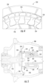
- FIG. 4 a schematic, axial view of the exemplary primary one-way clutch 220 is provided.
- the exemplary sprag clutch depicted includes a plurality of sprags 224 positioned between an inner race 226 and an outer race 228.
- the inner race 226 is fixed to, or formed integrally with, the second shaft 222 and the outer race 228 is coupled to the output assembly 204.
- the plurality of sprags 224 provide substantially no resistance to such movement.
- inclusion of the primary one-way clutch 220 within the turning unit 200 may allow for the electric motor 202 to rotate one or more accessory gears 106 of the accessory gearbox 100 (and, in turn, rotate one or more components of a compressor section or a turbine section of a gas turbine engine) when the gas turbine engine is in a shutdown operating condition. Additionally, inclusion of the primary one-way clutch 220 within the turning unit 200 prevents a rotation of the accessory gears 106 of the accessory gearbox 100 from being transferred back through the turning unit 200 to the electric machine 202, e.g., during flight operations of the gas turbine engine wherein such components of the accessory gearbox 100 are rotating much more quickly than is desirable for the electric motor 202. Such a configuration may therefore increase a useful life of the turning unit 200.
- the lubrication oil system includes a lubrication oil delivery cavity 234 defined within the outer race 228 of the primary one-way clutch 220.
- a supply line 236 is also included providing lubrication oil to the lubrication oil delivery cavity 234 through a stationary to rotating connection member 238.
- the connection member 238 is a stationery member (i.e., stationary relative to the outer race 228) defining an opening 240 configured to align with the lubrication oil delivery cavity 234 defined within the outer race 228 and provide the lubrication oil thereto during operation.
- the supply line 236 may receive lubrication oil from a lubrication oil jet (not shown) within the accessory gearbox 100 of the gas turbine engine.
- the outer race 228 of the primary one-way clutch 220 further defines an outlet channel 244 configured to receive at least a portion of the flow 245 of lubrication oil and expel it to an outer cavity 246 within the turning assembly.
- the outer cavity 246 may in turn, provide such flow 245 of lubrication oil to an outlet line 248, which may return the lubrication oil to the accessory gearbox 100.
- a lubrication oil system in accordance with the present disclosure may ensure the plurality of bearings, including the forward and aft bearings 230, 232, of the primary one-way clutch 220 are provided with a desired amount of lubrication oil during operation. It should be appreciated, however, that in other exemplary embodiments, any other suitable lubrication oil system may be provided.
- the exemplary turning unit 200 depicted further includes a controller 282.
- the controller 282 is operably connected to the motor 202 of the turning unit 200, and is further operably connected to the power source for the motor 202, such as the ground power source 206.
- the controller 282 is operably connected to the motor 202 via a wired connection 284, and similarly, the ground power source 206 is electrically connected to the motor 202 via a wired connection 286.
- the turning unit 200 includes a temperature sensor 288 positioned in or around the electric motor 202 for determining a temperature in or around the electric motor 202 ( FIG. 3 ).
- the temperature sensor 288 is similarly operably connected to the controller 282 via, for the embodiment depicted, a wired connection 290.
- the electric motor 202 is operable to rotate, through the output assembly 204, one or more components of the compressor section or the turbine section of the gas turbine engine at a relatively low rotational speed during a shutdown condition of the gas turbine engine. More specifically, for the embodiment depicted, the controller 282 is configured to operate the electric motor 202, such that the electric motor 202 is operable in such a manner.
- rotating the gas turbine engine at the relatively low rotational speed during the shutdown condition of the gas turbine engine may include rotating the gas turbine engine substantially continuously for at least a predetermined amount of time (e.g., at least about one hour, such as at least about two hours, such as at least about five hours).
- the controller 282 may determine the gas turbine engine is in a shutdown condition based on a torque applied by the electric motor 202 through the turning unit 200 to the accessory gearbox 100. For example, if an amount of torque applied by the electric motor 202 is below a predetermined minimum threshold, the controller 282 may also determine that either the gas turbine engine is operating and rotating more quickly than would otherwise be rotated by the electric motor 202, or alternatively that there has been a failure. Similarly, if an amount of torque applied by the electric motor 202 is above a predetermined maximum threshold, the controller 282 may also determine that there has been a failure.
- the controller 282 may determine the turning unit 200 is operating as desired to rotate the gas turbine engine at a relatively low rotational speed during a shutdown condition of the gas turbine engine.
- a turning unit in accordance with one or more exemplary embodiments of the present disclosure may therefore increase a useful life of a gas turbine engine with which it is installed, by reducing a likelihood of certain components deforming subsequent to flight operations due to the relatively high temperatures to which the components are exposed and the weight of the components being supported.
- the turning unit 200 is described herein as a device to prevent or minimize a likelihood of certain components deforming subsequent to flight operations, in certain exemplary embodiments, the turning unit may additionally, or alternatively, be used during inspection of the gas turbine engine through its borescope holes. With such a configuration, the turning unit may instead be permanently installed on the accessory gearbox at any suitably location on the accessory gearbox (such as a dedicated crank point).
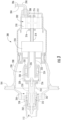
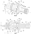
- FIGS. 6 and 7 an output assembly 204 is provided in accordance with an exemplary embodiment of the present disclosure.
- FIG. 6 provides a perspective view of the exemplary output assembly 204
- FIG. 7 provides a side, cross-sectional view of the output assembly 204.
- the exemplary output assembly 204 may be configured in substantially the same manner as the exemplary output assembly 204 described above with reference to, e.g., FIGS. 2 , 3 , and 5 . Accordingly, the exemplary output assembly 204 may be configured to transfer a rotational torque and power provided by an accessory system of the gas turbine engine to an accessory gearbox 100 of the gas turbine engine, or more particularly, to an accessory gear 106 of the accessory gearbox 100 of the gas turbine engine.
- the accessory system may be the exemplary turning unit 200 described above, in which case, the output assembly 204 may be configured to transfer rotational torque and power provided by the electric motor 202 (across the reduction gearbox 218 and the primary one-way clutch 220) to the gas turbine engine via the accessory gearbox 100.
- the exemplary output assembly 204 of FIGS. 6 and 7 may be utilized with any other suitable accessory system (such as a starter motor, etc.).
- the exemplary output assembly 204 depicted generally defines an axial direction A2 extending along an axis 251 of the output assembly 204, a radial direction R2, and a circumferential direction C2.
- the output assembly 204 generally includes a first rotating member 250 extending along the axis 251 and a second rotating member 252 also extending along the axis 251.
- the first rotating member 250 includes a mechanical connector for coupling the output assembly 204 to the accessory system.
- the mechanical connector is configured as a spline 254 configured to mesh with a spline, or splined coupling, of the accessory system.
- the spline 254 of the first rotating member 250 is configured to mesh with a splined coupling 256 rigidly connected to the outer race 228 of the primary one-way clutch 220 (see FIG. 3 ).
- the second rotating member 252 includes a mechanical connector for coupling the output assembly 204 to the accessory gearbox, or more specifically, to an accessory gear 106 of the accessory gearbox 100.
- the mechanical connector of the second rotating member 252 is configured as a spline 258 configured to mesh with a spline, or splined coupling 260, of the accessory gear 106 of the accessory gearbox 100 (see, e.g., FIG. 3 ).
- the first rotating member 250 is configured to mechanically couple the output assembly 204 to the accessory system
- the second rotating member 252 is configured to mechanically couple the output assembly 204 to the accessory gearbox.
- the second rotating member 252 is coupled to the first rotating member 250 at a first axial position 259 and at a second axial position 261.
- the first and second axial positions 259, 261 are spaced from one another along the axial direction A2 of the output assembly 204.
- the second rotating member 252 is slidably coupled to the first rotating member 250 at the first axial position 259, such that the connection permits movement of the second rotating member 252 relative to the first rotating member 250 along the axial direction A2 of the output assembly 204.
- the connection may be a splined connection, or any other suitable connection allowing for relative movement along the axial direction A2.
- connection allows for movement along the axial direction, A2
- the connection restricts any movement of the first rotating member 250 relative to the second rotating member 252 along the circumferential direction C2. Therefore, a rotational torque and power may be transferred from the second rotating member 252 to the first rotating member 250 (and vice versa) through the connection at the first axial position 259.
- the second rotating member 252 is coupled to the first rotating member 250 at the second axial position 261 through a one-way clutch 262.
- the one-way clutch 262 is formed at least in part by the first rotating member 250 and at least in part by the second rotating member 252. More specifically, for the embodiment depicted, the one-way clutch 262 is configured as a one-way dog clutch, also referred to simply as a "dog clutch". More specifically, for the embodiment depicted the auxiliary one-way clutch 262 is formed of a plurality of teeth 264 of the first rotating member 250 and a plurality of teeth 266 of the second rotating member 252.
- Each of these plurality of teeth 264, 266 include a first, active engagement end 268 and a second, passive end 270.
- the first and second ends 268, 270 are positioned at opposite sides of the respective teeth 264, 266 along the circumferential direction C2 of the output assembly 204.
- the first, active engagement ends 268 are each substantially aligned with the axial direction A2 of the output assembly 204 (i.e., with a plane defined by the axial direction A2 and the radial direction R2), such that the first end 268 of a tooth 264 on the first rotating member 250 may transfer power and torque to the first end 268 of a tooth 266 on the second rotating member 252.
- the second, passive ends 270 are slanted with respect to the axial direction A2 of the output assembly 204 (i.e., define an angle with a plane defined by the axial direction A2 and the radial direction R2, such as an angle greater than about twenty degrees), such that the second end 270 of a tooth 264 on the first rotating member 250 may not transfer any substantial amount of power or torque to the second end 270 of a tooth 266 of the second rotating member 252. Or, more notably, the second end 270 of a tooth 266 on the second rotating member 252 may not transfer any substantial amount of power or torque to the second end 270 of a tooth 264 on the first rotating member 250.
- the output assembly 204 defines a first rotational direction RD1 along the circumferential direction C2 and a second (and opposite) rotational direction RD2 along the circumferential direction C2.
- the first rotational direction RD2 may be a clockwise rotational direction (as viewed from an end of the first rotating member 250) and the second rotational direction RD2 may be a counterclockwise rotational direction, each being opposite one another along the circumferential direction C2.
- the accessory system may rotate the first rotating member 250 in the second rotational direction RD2, such that the spline 254 is the driving member and the spline 258 is the driven member.
- the accessory gearbox 100 may rotate the second rotating member 252 in the second rotational direction RD2, such that the spline 258 is the driving member, and the spline 254 is the driven member.
- the passive ends 270 of the teeth 264, 266 of the one-way clutch 262 are pressed against one another, and may move past one another, such that no substantial amount of power and/or torque may be transferred between the first and second rotating members 250, 252 (e.g., less than about 1 Newton-meter).
- the exemplary output assembly 204 further includes a spring member 272, which for the embodiment depicted, is coupled (or more specifically, is rigidly coupled) to the first rotating member 250. More specifically, for the embodiment depicted, the second rotating member 252 defines an opening 274 along the axial direction A2 at the first axial position 259. Additionally, the first rotating member 250 includes an extension member 278 extending from a body section 279 and generally along the axial direction A2 at least partially between the first axial position 259 and the second axial position 261. Further, for the embodiment depicted, the extension member 278 further extends through the opening 274 defined by the second rotating member 252.
- the spring member 272 of the output assembly 204 is attached to the extension member 278 at a third axial position 280, the third axial position 280 being spaced from the first axial position 259 along the axial direction A2.
- the spring member 272 extends to the second rotating member 252 at a distal end 276 of the second rotating member 252, pressing the teeth 266 of the second rotating member 252 towards the teeth 264 of the first rotating member 250.
- the second rotating member 252 is, for the embodiment depicted, slidably attached to the first rotating member 250 at the first axial position 259, such that the spring member 272 presses together the one-way clutch 262 formed by the first and second rotating members 250, 252.
- the spring member 272 creates a resistance for the one-way clutch 262 when moved in a passive direction (e.g., when the second rotating member 252 is moved in the second rotational direction RD2 by the accessory gearbox 100).
- each of the teeth 264, 266 include a distal end surface 282 configured to contact a recessed surface 284 of the opposing side of the one-way dog clutch 262. The pressing of these two surfaces 282, 284 together by, e.g., the spring member 272, creates a resistance that must be overcome in order to rotate the first rotating member 250 relative to the second rotating member 252 in the passive direction.
- the output assembly 204 further includes a designed fail point 285. More particularly, the extension member 278 includes the designed fail point 285.
- the designed fail point 285 is, for the embodiment depicted, configured as a shear neck.
- shear neck refers to a position on the extension member 278 defining a minimum diameter.
- a diameter 289 of the shear neck is at least about ten percent less than a diameter 291 of a body portion 292 of the extension member 278.
- the diameter 289 of the shear neck may be at least about fifteen percent less, such as at least about twenty percent less, such as at least about twenty-five percent less, and up to about ninety percent less than the diameter 291 of the body portion 292 of the extension member 278.
- the designed fail point 285 may instead have any other suitable configuration.
- designed fail point 285 may instead be a position on the extension member 278 having a plurality of holes or voids therein to reduce a torque limit of such portion of the extension member 278.
- the output assembly 204 is designed to allow for relatively high amount of torque to be transferred when rotated in one manner (e.g., when the accessory system rotates the first rotating member 250 in the second rotational direction RD2), while preventing such high amount of torque to be transferred when rotated in another manner (e.g., when the accessory gearbox 100 rotates the second rotating member 252 in second rotational direction RD2).
- the exemplary output assembly 204 depicted defines two separate torque paths when rotating in the second rotational direction RD2-a first in which the spline 254 is the driving member and a second in which the spline 258 is the driving member. More specifically, the first torque path extends from the spline 254 of the first rotating member 250, through the one-way clutch 262 to the second rotating member 252 (more specifically, through the engagement ends 268 of the teeth 264, 266 of the one-way clutch 262), and through spline 258 of the second rotating member 252.
- the second torque path extends primarily from the spline 254 of the first rotating member 250, through the extension member 278 of the first rotating member 250 (and through the designed fail point 285), through the connection of the first and second rotating members 250, 252 at the first axial position 259 to the second rotating member 252, and through the spline 258 of the second rotating member 252.
- a portion of the second torque path also extends through the one-way clutch in the form of friction resistance between the surfaces 282, 284 described above.
- the output assembly 204 defines a first torque limit through the first torque path and a second torque limit through the second torque path.
- the second torque limit is set mainly by the designed fail point 285.
- the output assembly 204 may accommodate a torque transfer in an amount up to the first torque limit when the first rotating member 250 is rotated in the second rotational direction RD2 by the accessory system (in which the spline 254 is the driving member) and may accommodate a torque transfer an amount up to the second torque limit when the second rotating member 252 is rotated in the second rotational direction RD2 by an accessory gear 106 of an accessory gearbox 100 (in which the spline 258 is the driving member).
- the first torque limit is greater than the second torque limit.
- the second torque limit may be at least about twenty-five percent lower than the first torque limit, such as at least about thirty-five percent lower, such as at least about fifty percent lower, such as at least about sixty percent lower, and up to about ninety-nine percent lower than the first torque limit.
- the second torque limit is set mainly by the designed fail point 285. More specifically, the second torque limit is set by the designed fail point 285 and the friction between the surfaces 282, 284.
- the designed fail point 285 defines a torque limit between about thirty (30) Newton-meters and about one (1) Newton-meter.
- the designed fail point 285 may define a torque limit less than about twenty-five Newton-meters, such as less than about twenty Newton-meters.
- the overall second torque limit may be within about one Newton-meter of the torque limit of the designed fail point 285.
- the first torque limit may be greater than the second torque limit.
- the first torque limit may be greater than thirty Newton-meters, such as greater than about fifty Newton-meters, such as greater than about seventy-five Newton-meters, such as greater than about one hundred Newton-meters, and up to about 5,000 Newton-meters.
- Inclusion of an output assembly to mechanically couple the accessory system to an accessory gearbox of the gas turbine engine in accordance with an embodiment of the present disclosure may ensure that undesirable, relatively high rotational speeds and/or torques of the accessory gearbox are not transferred to the accessory system. Such may increase a longevity of the accessory system.
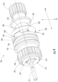
- FIGS. 8 and 9 an output assembly 204 in accordance with another exemplary embodiment of the present disclosure is depicted.
- FIG. 8 provides an exploded view of the exemplary output assembly 204
- FIG. 9 provides an assembled view of the exemplary output assembly 204.
- the exemplary output assembly 204 of FIGS. 8 and 9 may be configured in substantially the same manner as the exemplary output assembly 204 of FIGS. 6 and 7 . Accordingly, the same numbering may refer to the same similar parts.
- the exemplary output assembly 204 of FIGS. 8 and 9 generally includes a first rotating member 250 and a second rotating member 252.
- the second rotating member 252 is coupled to the first rotating member 250 at a first axial position 259 and at a second axial position 261.
- the second rotating member 252 is coupled to the first rotating member 250 at the second axial position 261 through a one-way clutch 262.
- the second rotating member 252 is slidably coupled to the first rotating member 250 at the first axial position 259, such that the connection permits movement of the second rotating member 252 relative to the first rotating member 250 along the axial direction A2 of the output assembly 204.
- the slidable connection between the second rotating member 252 and the first rotating member 250 is provided by an extension member 278 including two opposing substantially flat surfaces 294 and an opening 274 at a distal end 226 of the second rotating member 252 being an elongated opening having a shape corresponding to the opposing substantially flat surfaces 294 of the extension member 278 of the first rotating member 250.
- the first rotating member 250 may be slidable relative to the second rotating member 254 along the axial direction A2, without being rotatable relative to one another at the first axial position 259.
- the output assembly 204 of FIGS. 8 and 9 is depicted without a spring member 272 for clarity.
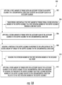
- the gas turbine engine may generally include a compressor section, a combustion section, a turbine section, an accessory gearbox, an accessory system, and an output assembly.
- the accessory gearbox may be attached to, e.g., a core turbine engine of the gas turbine engine.
- the exemplary method generally includes at (302) applying a first amount of torque with an accessory system to an output assembly in a circumferential direction to rotate an accessory gear of an accessory gearbox.
- applying the first amount of torque with the accessory system to the output assembly at (302) includes at (304) transferring substantially the first amount of torque from a second rotating member of the output assembly to a first rotating member of the output assembly through a one-way clutch.
- the exemplary method 300 additionally includes at (306) applying a second amount of torque with the accessory gear of the accessory gearbox to the output assembly in the circumferential direction (i.e., the same rotational direction as at step (302), such as a second circumferential direction; see FIGS. 6 and 7 ).
- the first and second amounts of torque are each greater than or equal to a torque limit, and more specifically, are each greater than or equal to a torque limit of a designed fail point of an extension member of the first rotating member. Additionally, for the embodiment depicted, the first amount of torque is greater than the second amount of torque.
- the exemplary method 300 additionally includes at (308) shearing a portion of the output assembly in response to the application of the second amount of torque to the output assembly in the circumferential direction at (306). More particularly, for the exemplary aspect depicted, shearing the portion of the output assembly in response to the application of the second amount of torque with the accessory gear to the output assembly in the circumferential direction at (308) includes at (310) shearing the extension member of the first rotating member at the designed fail point.
- the designed fail point may be a shear neck.
- the exemplary method 300 includes at (312) applying a third amount of torque with the accessory gear of the accessory gearbox to the output assembly in the circumferential direction subsequent to shearing the portion of the output assembly at (308) such that a second rotating member of the output assembly rotates in the circumferential direction relative to the first rotating member of the output assembly.
Landscapes
- Engineering & Computer Science (AREA)
- General Engineering & Computer Science (AREA)
- Mechanical Engineering (AREA)
- Chemical & Material Sciences (AREA)
- Combustion & Propulsion (AREA)
- Connection Of Motors, Electrical Generators, Mechanical Devices, And The Like (AREA)
- Retarders (AREA)
- Structures Of Non-Positive Displacement Pumps (AREA)
Claims (13)
- Abtriebsanordnung (204) für ein Hilfsgerätesystem eines Gasturbinentriebwerks, wobei das Gasturbinentriebwerk ein Hilfsgerätegetriebe (100) umfasst, wobei die Abtriebsanordnung (204) eine Achse (251) definiert und umfasst:ein erstes rotierendes Element (250), das sich entlang der Achse (251) erstreckt und einen mechanischen Verbinder zum Koppeln der Abtriebsanordnung (204) mit dem Hilfsgerätesystem umfasst;ein zweites rotierendes Element (252), das sich entlang der Achse (251) erstreckt und ein gegenüberliegendes erstes Ende und zweites Ende umfasst, wobei das erste Ende eine Öffnung (274) umfasst, das zweite rotierende Element (252) an einer ersten axialen Position (259) an der Öffnung (274) des ersten Endes und an einer zweiten axialen Position (261) an dem zweiten Ende mit dem ersten rotierenden Element (250) gekoppelt ist;eine Freilaufkupplung (262), wobei das zweite rotierende Element (252) durch die Freilaufkupplung (262) an der zweiten axialen Position (261) mit dem ersten rotierenden Element (250) gekoppelt ist;wobei das erste rotierende Element (250) ferner ein Verlängerungselement umfasst, das sich mindestens teilweise zwischen der ersten axialen Position (259) und der zweiten axialen Position (261) und durch die Öffnung (274) des ersten Endes an der ersten axialen Position erstreckt, wobei das Verlängerungselement eine vorgesehene Ausfallstelle (285) umfasst, wobei der Abtrieb ferner umfasst;ein Federelement (272), das an dem Verlängerungselement angebracht ist und die Freilaufkupplung zusammendrückt,wobei die Freilaufkupplung mindestens teilweise über das erste rotierende Element (25) und mindestens teilweise über das zweite rotierende Element (252) ausgebildet wird,das Federelement (272) an einer dritten axialen Position (259) entlang einer axialen Richtung A2, die sich entlang einer Achse (251) der Abtriebsanordnung (204) erstreckt, an dem Verlängerungselement angebracht ist,und das Federelement (272) sich bis zu dem zweiten rotierenden Element (252) an dem ersten Ende erstreckt.
- Abtriebsanordnung (204) nach Anspruch 1, wobei die vorgesehene Bruchstelle (285) ein Scherhals ist.
- Abtriebsanordnung (204) nach Anspruch 1, wobei die Freilaufkupplung (262) als eine Klauenkupplung konfiguriert ist.
- Abtriebsanordnung (204) nach Anspruch 1, wobei das zweite rotierende Element (252) einen mechanischen Verbinder zum Koppeln der Abtriebsanordnung (204) mit dem Hilfsgerätegetriebe (100) umfasst.
- Abtriebsanordnung (204) nach Anspruch 4, wobei der mechanische Verbinder des ersten rotierenden Elements (250) als eine Keilwelle ausgebildet ist und wobei der mechanische Verbinder des zweiten rotierenden Elements (252) ebenso als eine Keilwelle ausgebildet ist.
- Abtriebsanordnung (204) nach Anspruch 1, wobei die vorgesehene Bruchstelle (285) eine Drehmomentgrenze von kleiner als etwa dreißig Newtonmeter definiert.
- Abtriebsanordnung nach Anspruch 1, wobei die Abtriebsanordnung (204) eine erste Drehmomentgrenze definiert, wenn das erste rotierende Element (250) über das Hilfsgerätesystem in eine erste Umfangsrichtung rotiert wird, wobei die Abtriebsanordnung (204) eine zweite Drehmomentgrenze definiert, wenn das zweite rotierende Element (252) über ein Hilfsgerätezahnrad des Hilfsgerätegetriebes (100) in die erste Umfangsrichtung rotiert wird, und wobei die erste Drehmomentgrenze größer als die zweite Drehmomentgrenze ist.
- Abtriebsanordnung nach Anspruch 6, wobei die erste Drehmomentgrenze größer als dreißig Newtonmeter ist und wobei die zweite Drehmomentgrenze kleiner als dreißig Newtonmeter ist.
- Ausgangsanordnung nach Anspruch 1, wobei das zweite rotierende Element (252) an der ersten axialen Position (259) entlang der Achse (251) mit dem ersten rotierenden Element (250) verschieblich gekoppelt ist.
- Gasturbinentriebwerk, umfassend:einen Kompressorabschnitt und einen Turbinenabschnitt;ein Hilfsgerätegetriebe (100), das mit einer oder mehreren Komponenten des Kompressorabschnitts oder des Turbinenabschnitts mechanisch gekoppelt ist; undeine Abtriebsanordnung (204) nach einem der vorstehenden Ansprüche.
- Verfahren zum Betreiben eines Hilfsgerätesystems eines Gasturbinentriebwerks, umfassend:Anwenden einer ersten Menge an Drehmoment mit einem Hilfsgerätesystem auf eine Abtriebsanordnung (204) in einer Umfangsrichtung, um ein Hilfsgerätezahnrad eines Hilfsgerätegetriebes (100) zu rotieren, wobei die Abtriebsanordnung (204) mit einem der Ansprüche 1 bis 9 übereinstimmt;Anwenden einer zweiten Menge an Drehmoment mit dem Hilfsgerätezahnrad des Hilfsgerätegetriebes (100) auf die Abtriebsanordnung (204) in der Umfangsrichtung, wobei die erste und die zweite Menge an Drehmoment jeweils größer als oder gleich einer Drehmomentgrenze sind; undAbscheren eines Stücks der Abtriebsanordnung (204) als Reaktion auf die Anwendung der zweiten Menge an Drehmoment auf die Abtriebsanordnung (204) in der Umfangsrichtung.
- Verfahren nach Anspruch 11, wobei die erste Menge an Drehmoment größer als die zweite Menge an Drehmoment ist.
- Verfahren nach Anspruch 11, wobei das Anwenden der ersten Menge an Drehmoment mit dem Hilfsgerätesystem auf die Abtriebsanordnung ein Übertragen im Wesentlichen der ersten Menge an Drehmoment von einem zweiten rotierenden Element (252) der Abtriebsanordnung auf ein erstes rotierendes Element (250) der Abtriebsanordnung durch die Freilaufkupplung (262) umfasst.
Priority Applications (3)
| Application Number | Priority Date | Filing Date | Title |
|---|---|---|---|
| EP17425038.1A EP3382164B1 (de) | 2017-03-28 | 2017-03-28 | Abtriebsanordnung für ein hilfsgetriebe eines gasturbinenmotors |
| US15/906,278 US11002318B2 (en) | 2017-03-28 | 2018-02-27 | Output assembly for an accessory gearbox of a gas turbine engine |
| CN201810265420.0A CN108661807B (zh) | 2017-03-28 | 2018-03-28 | 用于燃气涡轮发动机的附件变速箱的输出组件 |
Applications Claiming Priority (1)
| Application Number | Priority Date | Filing Date | Title |
|---|---|---|---|
| EP17425038.1A EP3382164B1 (de) | 2017-03-28 | 2017-03-28 | Abtriebsanordnung für ein hilfsgetriebe eines gasturbinenmotors |
Publications (2)
| Publication Number | Publication Date |
|---|---|
| EP3382164A1 EP3382164A1 (de) | 2018-10-03 |
| EP3382164B1 true EP3382164B1 (de) | 2024-12-25 |
Family
ID=58632322
Family Applications (1)
| Application Number | Title | Priority Date | Filing Date |
|---|---|---|---|
| EP17425038.1A Active EP3382164B1 (de) | 2017-03-28 | 2017-03-28 | Abtriebsanordnung für ein hilfsgetriebe eines gasturbinenmotors |
Country Status (3)
| Country | Link |
|---|---|
| US (1) | US11002318B2 (de) |
| EP (1) | EP3382164B1 (de) |
| CN (1) | CN108661807B (de) |
Families Citing this family (25)
| Publication number | Priority date | Publication date | Assignee | Title |
|---|---|---|---|---|
| US10465611B2 (en) | 2016-09-15 | 2019-11-05 | Pratt & Whitney Canada Corp. | Reverse flow multi-spool gas turbine engine with aft-end accessory gearbox drivingly connected to both high pressure spool and low pressure spool |
| US10794216B2 (en) * | 2018-06-19 | 2020-10-06 | Raytheon Technologies Corporation | Fan drive gear system DC motor and generator |
| FR3087424B1 (fr) * | 2018-10-22 | 2021-01-22 | Safran Trans Systems | Systeme de couplage/decouplage de boitiers d'accessoires |
| US10995675B2 (en) | 2019-02-19 | 2021-05-04 | Pratt & Whitney Canada Corp. | Gas turbine engine with accessory gearbox |
| US10954863B2 (en) * | 2019-04-09 | 2021-03-23 | General Electric Company | Phasing gearbox |
| CN110107667B (zh) * | 2019-04-28 | 2021-05-07 | 中国航发湖南动力机械研究所 | 涡轮发动机附件传动机构及其使用方法和涡轮发动机 |
| CN110043578A (zh) * | 2019-05-14 | 2019-07-23 | 许占欣 | 一种大扭矩单向传动装置 |
| WO2021051399A1 (zh) | 2019-09-20 | 2021-03-25 | 烟台杰瑞石油装备技术有限公司 | 一种利用涡轮发动机驱动柱塞泵的水力压裂系统 |
| US12540575B2 (en) | 2019-09-06 | 2026-02-03 | Yantai Jereh Petroleum Equipment & Technologies Co., Ltd. | Hydraulic fracturing system for driving a plunger pump with a turbine engine and noise reduction thereof |
| US11702919B2 (en) | 2019-09-20 | 2023-07-18 | Yantai Jereh Petroleum Equipment & Technologies Co., Ltd. | Adaptive mobile power generation system |
| US11519395B2 (en) | 2019-09-20 | 2022-12-06 | Yantai Jereh Petroleum Equipment & Technologies Co., Ltd. | Turbine-driven fracturing system on semi-trailer |
| US12264568B2 (en) | 2019-09-20 | 2025-04-01 | Yantai Jereh Petroleum Equipment & Technologies Co., Ltd. | Fracturing devices |
| CN112901292B (zh) | 2021-03-30 | 2025-12-09 | 烟台杰瑞石油装备技术有限公司 | 排气装置及其安装方法、涡轮压裂设备 |
| US12234712B2 (en) | 2019-09-20 | 2025-02-25 | Yantai Jereh Petroleum Equipment & Technologies Co., Ltd. | Adaptive mobile power generation system |
| US12163514B2 (en) | 2019-09-20 | 2024-12-10 | Yantai Jereh Petroleum Equipment & Technologies Co., Ltd. | Connecting structure, plunger pump device and generator device |
| CN113047916A (zh) | 2021-01-11 | 2021-06-29 | 烟台杰瑞石油装备技术有限公司 | 可切换设备、井场及其控制方法、设备以及存储介质 |
| CN110485982A (zh) | 2019-09-20 | 2019-11-22 | 烟台杰瑞石油装备技术有限公司 | 一种涡轮压裂设备 |
| US12410695B2 (en) | 2019-09-20 | 2025-09-09 | Yantai Jereh Petroleum Equipment & Technologies Co., Ltd. | Turbine fracturing equipment |
| US12065916B2 (en) | 2019-09-20 | 2024-08-20 | Yantai Jereh Petroleum Equipment & Technologies Co., Ltd. | Hydraulic fracturing system for driving a plunger pump with a turbine engine |
| PL433297A1 (pl) * | 2020-03-19 | 2021-09-20 | Unison Industries, Llc | Odsprzęgacz dla rozrusznika silnika |
| US12006056B2 (en) * | 2020-10-29 | 2024-06-11 | Hybrid Project Llc | Dual drive hybrid electric power plant for aircraft |
| US12571438B2 (en) * | 2021-03-11 | 2026-03-10 | General Electric Company | Turboshaft engine clutch configuration |
| US11788427B2 (en) * | 2021-06-10 | 2023-10-17 | Pratt & Whitney Canada Corp. | Lubricant pump system and method for aircraft engine |
| US11821372B2 (en) * | 2021-06-11 | 2023-11-21 | Rtx Corporation | Hybrid electric engine with electric tip clearance mechanism |
| US20260022669A1 (en) * | 2024-07-22 | 2026-01-22 | The Boeing Company | Accessory Gearbox with Accessories with a Stacked Configuration |
Citations (3)
| Publication number | Priority date | Publication date | Assignee | Title |
|---|---|---|---|---|
| US4871296A (en) * | 1988-11-07 | 1989-10-03 | Allied-Signal Inc. | Decoupler shaft and air turbine starter having such a decoupler |
| US6059085A (en) * | 1998-12-17 | 2000-05-09 | Alliedsignal Inc. | Shaft decoupler |
| US20070000746A1 (en) * | 2005-06-30 | 2007-01-04 | Microturbo Sa | Decoupling sleeve |
Family Cites Families (22)
| Publication number | Priority date | Publication date | Assignee | Title |
|---|---|---|---|---|
| US2964931A (en) * | 1958-06-20 | 1960-12-20 | Garrett Corp | Reversible shear output shaft |
| US2951570A (en) * | 1958-11-25 | 1960-09-06 | Gen Electric | Starter decoupling means |
| US2942481A (en) * | 1959-01-08 | 1960-06-28 | Bendix Aviat Corp | Starter having reverse torque release |
| US3220218A (en) * | 1963-12-30 | 1965-11-30 | Gen Electric | Device for disconnecting engine driven aircraft accessories |
| US3365614A (en) | 1965-05-06 | 1968-01-23 | Westinghouse Electric Corp | Apparatus for detecting substantially zero speed of a rotatable device |
| FR2529976B1 (fr) * | 1982-07-08 | 1986-11-28 | Hispano Suiza Sa | Dispositif de desaccouplage de deux machines tournantes |
| US4768634A (en) * | 1986-12-22 | 1988-09-06 | Sundstrand Corporation | Backdrive overload release clutch |
| US5210704A (en) | 1990-10-02 | 1993-05-11 | Technology International Incorporated | System for prognosis and diagnostics of failure and wearout monitoring and for prediction of life expectancy of helicopter gearboxes and other rotating equipment |
| US5319989A (en) * | 1992-08-20 | 1994-06-14 | Allied-Signal Inc. | Gas turbine starter incorporating wear-resistant slip clutch |
| FR2735239B1 (fr) | 1995-06-08 | 1997-08-08 | Eurocopter France | Systeme pour la detection et la surveillance de la vitesse de rotation d'au moins un rotor et de la vitesse de rotation d'au moins un moteur d'un aeronef a voilure tournante, tel qu'un helicoptere |
| GB9616577D0 (en) | 1996-08-07 | 1996-09-25 | Lucas Ind Plc | Improvements relating to gearboxes |
| DE19653962A1 (de) | 1996-12-21 | 1998-06-25 | Bosch Gmbh Robert | Vorrichtung zum Erfassen von Drehmomenten |
| FR2920382B1 (fr) | 2007-08-31 | 2009-10-30 | Renault Sas | Dispositif et procede de determination d'une cartographie du couple transmis par un embrayage equipant un vehicule automobile. |
| US8105018B2 (en) * | 2008-02-13 | 2012-01-31 | Honeywell International Inc. | Decoupler devices to prevent backdrive in air turbine starters |
| US8568089B2 (en) * | 2010-06-03 | 2013-10-29 | Hamilton Sundstrand Corporation | Gear arrangement |
| US8364424B2 (en) | 2010-07-30 | 2013-01-29 | General Electric Company | System and method for monitoring a wind turbine gearbox |
| US8876476B2 (en) * | 2010-11-16 | 2014-11-04 | Hamilton Sundstrand Corporation | Integrated accessory gearbox and engine starter |
| CN202500908U (zh) * | 2012-03-08 | 2012-10-24 | 中国南方航空工业(集团)有限公司 | 传动装置及具有该传动装置的燃气轮机 |
| CA2965272A1 (en) * | 2014-10-22 | 2016-04-28 | Paolo Altamura | Accessory assembly of a turbine engine |
| US20160178464A1 (en) | 2014-12-19 | 2016-06-23 | Rolls-Royce Corporation | Torque sensor monitoring for gas turbine engine |
| US9897010B2 (en) * | 2015-03-30 | 2018-02-20 | Honeywell International Inc. | Air turbine starter systems including gearbox-integrated clutch modules and gas turbine engines employing the same |
| US10473164B2 (en) * | 2016-07-05 | 2019-11-12 | Hamilton Sundstrand Corporation | Mechanical shear fuse for engine motoring system |
-
2017
- 2017-03-28 EP EP17425038.1A patent/EP3382164B1/de active Active
-
2018
- 2018-02-27 US US15/906,278 patent/US11002318B2/en active Active
- 2018-03-28 CN CN201810265420.0A patent/CN108661807B/zh active Active
Patent Citations (3)
| Publication number | Priority date | Publication date | Assignee | Title |
|---|---|---|---|---|
| US4871296A (en) * | 1988-11-07 | 1989-10-03 | Allied-Signal Inc. | Decoupler shaft and air turbine starter having such a decoupler |
| US6059085A (en) * | 1998-12-17 | 2000-05-09 | Alliedsignal Inc. | Shaft decoupler |
| US20070000746A1 (en) * | 2005-06-30 | 2007-01-04 | Microturbo Sa | Decoupling sleeve |
Also Published As
| Publication number | Publication date |
|---|---|
| CN108661807B (zh) | 2021-08-24 |
| CN108661807A (zh) | 2018-10-16 |
| US11002318B2 (en) | 2021-05-11 |
| EP3382164A1 (de) | 2018-10-03 |
| US20180283464A1 (en) | 2018-10-04 |
Similar Documents
| Publication | Publication Date | Title |
|---|---|---|
| EP3382164B1 (de) | Abtriebsanordnung für ein hilfsgetriebe eines gasturbinenmotors | |
| US11536202B2 (en) | Gas turbine engine turning system | |
| CA2987227C (en) | Hybrid-electric drive system | |
| US11473441B2 (en) | Embedded electric machine | |
| EP3282093B1 (de) | Getriebeturbolüfter mit niederdruckleistungsextraktion | |
| US9970352B2 (en) | Turbomachine fan clutch | |
| EP2961970B1 (de) | Gasturbinenanordnung sowie verfahren zur steuerung der rotation eines gasturbinenfans | |
| US11506067B2 (en) | Gas turbine engine with clutch assembly | |
| US10006520B2 (en) | System for regulating stresses in ring gears | |
| US20260028919A1 (en) | Lubrication system for a turbine engine | |
| US12560101B2 (en) | Lubrication system for a turbine engine | |
| US20250020070A1 (en) | Lubrication system for a turbine engine | |
| CN119801728A (zh) | 用于涡轮发动机的润滑系统 | |
| CN120444140A (zh) | 用于涡轮发动机的齿轮箱组件 | |
| US12516627B2 (en) | Gas turbine engine | |
| CN117469347A (zh) | 周转齿轮箱中的行星齿轮间隙 |
Legal Events
| Date | Code | Title | Description |
|---|---|---|---|
| STAA | Information on the status of an ep patent application or granted ep patent |
Free format text: STATUS: UNKNOWN |
|
| PUAI | Public reference made under article 153(3) epc to a published international application that has entered the european phase |
Free format text: ORIGINAL CODE: 0009012 |
|
| STAA | Information on the status of an ep patent application or granted ep patent |
Free format text: STATUS: THE APPLICATION HAS BEEN PUBLISHED |
|
| AK | Designated contracting states |
Kind code of ref document: A1 Designated state(s): AL AT BE BG CH CY CZ DE DK EE ES FI FR GB GR HR HU IE IS IT LI LT LU LV MC MK MT NL NO PL PT RO RS SE SI SK SM TR |
|
| AX | Request for extension of the european patent |
Extension state: BA ME |
|
| STAA | Information on the status of an ep patent application or granted ep patent |
Free format text: STATUS: REQUEST FOR EXAMINATION WAS MADE |
|
| 17P | Request for examination filed |
Effective date: 20190403 |
|
| RBV | Designated contracting states (corrected) |
Designated state(s): AL AT BE BG CH CY CZ DE DK EE ES FI FR GB GR HR HU IE IS IT LI LT LU LV MC MK MT NL NO PL PT RO RS SE SI SK SM TR |
|
| STAA | Information on the status of an ep patent application or granted ep patent |
Free format text: STATUS: EXAMINATION IS IN PROGRESS |
|
| 17Q | First examination report despatched |
Effective date: 20210903 |
|
| GRAP | Despatch of communication of intention to grant a patent |
Free format text: ORIGINAL CODE: EPIDOSNIGR1 |
|
| STAA | Information on the status of an ep patent application or granted ep patent |
Free format text: STATUS: GRANT OF PATENT IS INTENDED |
|
| INTG | Intention to grant announced |
Effective date: 20240717 |
|
| GRAS | Grant fee paid |
Free format text: ORIGINAL CODE: EPIDOSNIGR3 |
|
| GRAA | (expected) grant |
Free format text: ORIGINAL CODE: 0009210 |
|
| STAA | Information on the status of an ep patent application or granted ep patent |
Free format text: STATUS: THE PATENT HAS BEEN GRANTED |
|
| AK | Designated contracting states |
Kind code of ref document: B1 Designated state(s): AL AT BE BG CH CY CZ DE DK EE ES FI FR GB GR HR HU IE IS IT LI LT LU LV MC MK MT NL NO PL PT RO RS SE SI SK SM TR |
|
| REG | Reference to a national code |
Ref country code: GB Ref legal event code: FG4D |
|
| REG | Reference to a national code |
Ref country code: CH Ref legal event code: EP |
|
| REG | Reference to a national code |
Ref country code: DE Ref legal event code: R096 Ref document number: 602017086930 Country of ref document: DE |
|
| REG | Reference to a national code |
Ref country code: IE Ref legal event code: FG4D |
|
| P01 | Opt-out of the competence of the unified patent court (upc) registered |
Free format text: CASE NUMBER: APP_65776/2024 Effective date: 20241212 |
|
| REG | Reference to a national code |
Ref country code: LT Ref legal event code: MG9D |
|
| PG25 | Lapsed in a contracting state [announced via postgrant information from national office to epo] |
Ref country code: HR Free format text: LAPSE BECAUSE OF FAILURE TO SUBMIT A TRANSLATION OF THE DESCRIPTION OR TO PAY THE FEE WITHIN THE PRESCRIBED TIME-LIMIT Effective date: 20241225 |
|
| PG25 | Lapsed in a contracting state [announced via postgrant information from national office to epo] |
Ref country code: FI Free format text: LAPSE BECAUSE OF FAILURE TO SUBMIT A TRANSLATION OF THE DESCRIPTION OR TO PAY THE FEE WITHIN THE PRESCRIBED TIME-LIMIT Effective date: 20241225 |
|
| PG25 | Lapsed in a contracting state [announced via postgrant information from national office to epo] |
Ref country code: BG Free format text: LAPSE BECAUSE OF FAILURE TO SUBMIT A TRANSLATION OF THE DESCRIPTION OR TO PAY THE FEE WITHIN THE PRESCRIBED TIME-LIMIT Effective date: 20241225 |
|
| PG25 | Lapsed in a contracting state [announced via postgrant information from national office to epo] |
Ref country code: NO Free format text: LAPSE BECAUSE OF FAILURE TO SUBMIT A TRANSLATION OF THE DESCRIPTION OR TO PAY THE FEE WITHIN THE PRESCRIBED TIME-LIMIT Effective date: 20250325 |
|
| PG25 | Lapsed in a contracting state [announced via postgrant information from national office to epo] |
Ref country code: GR Free format text: LAPSE BECAUSE OF FAILURE TO SUBMIT A TRANSLATION OF THE DESCRIPTION OR TO PAY THE FEE WITHIN THE PRESCRIBED TIME-LIMIT Effective date: 20250326 Ref country code: LV Free format text: LAPSE BECAUSE OF FAILURE TO SUBMIT A TRANSLATION OF THE DESCRIPTION OR TO PAY THE FEE WITHIN THE PRESCRIBED TIME-LIMIT Effective date: 20241225 |
|
| PG25 | Lapsed in a contracting state [announced via postgrant information from national office to epo] |
Ref country code: RS Free format text: LAPSE BECAUSE OF FAILURE TO SUBMIT A TRANSLATION OF THE DESCRIPTION OR TO PAY THE FEE WITHIN THE PRESCRIBED TIME-LIMIT Effective date: 20250325 |
|
| REG | Reference to a national code |
Ref country code: NL Ref legal event code: MP Effective date: 20241225 |
|
| PG25 | Lapsed in a contracting state [announced via postgrant information from national office to epo] |
Ref country code: NL Free format text: LAPSE BECAUSE OF FAILURE TO SUBMIT A TRANSLATION OF THE DESCRIPTION OR TO PAY THE FEE WITHIN THE PRESCRIBED TIME-LIMIT Effective date: 20241225 |
|
| REG | Reference to a national code |
Ref country code: AT Ref legal event code: MK05 Ref document number: 1754325 Country of ref document: AT Kind code of ref document: T Effective date: 20241225 |
|
| PG25 | Lapsed in a contracting state [announced via postgrant information from national office to epo] |
Ref country code: SM Free format text: LAPSE BECAUSE OF FAILURE TO SUBMIT A TRANSLATION OF THE DESCRIPTION OR TO PAY THE FEE WITHIN THE PRESCRIBED TIME-LIMIT Effective date: 20241225 |
|
| PG25 | Lapsed in a contracting state [announced via postgrant information from national office to epo] |
Ref country code: PL Free format text: LAPSE BECAUSE OF FAILURE TO SUBMIT A TRANSLATION OF THE DESCRIPTION OR TO PAY THE FEE WITHIN THE PRESCRIBED TIME-LIMIT Effective date: 20241225 |
|
| PG25 | Lapsed in a contracting state [announced via postgrant information from national office to epo] |
Ref country code: ES Free format text: LAPSE BECAUSE OF FAILURE TO SUBMIT A TRANSLATION OF THE DESCRIPTION OR TO PAY THE FEE WITHIN THE PRESCRIBED TIME-LIMIT Effective date: 20241225 |
|
| PG25 | Lapsed in a contracting state [announced via postgrant information from national office to epo] |
Ref country code: IS Free format text: LAPSE BECAUSE OF FAILURE TO SUBMIT A TRANSLATION OF THE DESCRIPTION OR TO PAY THE FEE WITHIN THE PRESCRIBED TIME-LIMIT Effective date: 20250425 |
|
| PG25 | Lapsed in a contracting state [announced via postgrant information from national office to epo] |
Ref country code: PT Free format text: LAPSE BECAUSE OF FAILURE TO SUBMIT A TRANSLATION OF THE DESCRIPTION OR TO PAY THE FEE WITHIN THE PRESCRIBED TIME-LIMIT Effective date: 20250428 |
|
| PG25 | Lapsed in a contracting state [announced via postgrant information from national office to epo] |
Ref country code: EE Free format text: LAPSE BECAUSE OF FAILURE TO SUBMIT A TRANSLATION OF THE DESCRIPTION OR TO PAY THE FEE WITHIN THE PRESCRIBED TIME-LIMIT Effective date: 20241225 |
|
| PG25 | Lapsed in a contracting state [announced via postgrant information from national office to epo] |
Ref country code: AT Free format text: LAPSE BECAUSE OF FAILURE TO SUBMIT A TRANSLATION OF THE DESCRIPTION OR TO PAY THE FEE WITHIN THE PRESCRIBED TIME-LIMIT Effective date: 20241225 Ref country code: RO Free format text: LAPSE BECAUSE OF FAILURE TO SUBMIT A TRANSLATION OF THE DESCRIPTION OR TO PAY THE FEE WITHIN THE PRESCRIBED TIME-LIMIT Effective date: 20241225 |
|
| PG25 | Lapsed in a contracting state [announced via postgrant information from national office to epo] |
Ref country code: SK Free format text: LAPSE BECAUSE OF FAILURE TO SUBMIT A TRANSLATION OF THE DESCRIPTION OR TO PAY THE FEE WITHIN THE PRESCRIBED TIME-LIMIT Effective date: 20241225 |
|
| PG25 | Lapsed in a contracting state [announced via postgrant information from national office to epo] |
Ref country code: CZ Free format text: LAPSE BECAUSE OF FAILURE TO SUBMIT A TRANSLATION OF THE DESCRIPTION OR TO PAY THE FEE WITHIN THE PRESCRIBED TIME-LIMIT Effective date: 20241225 |
|
| PG25 | Lapsed in a contracting state [announced via postgrant information from national office to epo] |
Ref country code: IT Free format text: LAPSE BECAUSE OF FAILURE TO SUBMIT A TRANSLATION OF THE DESCRIPTION OR TO PAY THE FEE WITHIN THE PRESCRIBED TIME-LIMIT Effective date: 20241225 |
|
| PG25 | Lapsed in a contracting state [announced via postgrant information from national office to epo] |
Ref country code: SE Free format text: LAPSE BECAUSE OF FAILURE TO SUBMIT A TRANSLATION OF THE DESCRIPTION OR TO PAY THE FEE WITHIN THE PRESCRIBED TIME-LIMIT Effective date: 20241225 |
|
| REG | Reference to a national code |
Ref country code: DE Ref legal event code: R097 Ref document number: 602017086930 Country of ref document: DE |
|
| PG25 | Lapsed in a contracting state [announced via postgrant information from national office to epo] |
Ref country code: DK Free format text: LAPSE BECAUSE OF FAILURE TO SUBMIT A TRANSLATION OF THE DESCRIPTION OR TO PAY THE FEE WITHIN THE PRESCRIBED TIME-LIMIT Effective date: 20241225 |
|
| PG25 | Lapsed in a contracting state [announced via postgrant information from national office to epo] |
Ref country code: MC Free format text: LAPSE BECAUSE OF FAILURE TO SUBMIT A TRANSLATION OF THE DESCRIPTION OR TO PAY THE FEE WITHIN THE PRESCRIBED TIME-LIMIT Effective date: 20241225 |
|
| REG | Reference to a national code |
Ref country code: CH Ref legal event code: H13 Free format text: ST27 STATUS EVENT CODE: U-0-0-H10-H13 (AS PROVIDED BY THE NATIONAL OFFICE) Effective date: 20251023 |
|
| PLBE | No opposition filed within time limit |
Free format text: ORIGINAL CODE: 0009261 |
|
| STAA | Information on the status of an ep patent application or granted ep patent |
Free format text: STATUS: NO OPPOSITION FILED WITHIN TIME LIMIT |
|
| PG25 | Lapsed in a contracting state [announced via postgrant information from national office to epo] |
Ref country code: LU Free format text: LAPSE BECAUSE OF NON-PAYMENT OF DUE FEES Effective date: 20250328 |
|
| 26N | No opposition filed |
Effective date: 20250926 |
|
| REG | Reference to a national code |
Ref country code: BE Ref legal event code: MM Effective date: 20250331 |
|
| PG25 | Lapsed in a contracting state [announced via postgrant information from national office to epo] |
Ref country code: BE Free format text: LAPSE BECAUSE OF NON-PAYMENT OF DUE FEES Effective date: 20250331 |
|
| PG25 | Lapsed in a contracting state [announced via postgrant information from national office to epo] |
Ref country code: CH Free format text: LAPSE BECAUSE OF NON-PAYMENT OF DUE FEES Effective date: 20250331 |
|
| PG25 | Lapsed in a contracting state [announced via postgrant information from national office to epo] |
Ref country code: IE Free format text: LAPSE BECAUSE OF NON-PAYMENT OF DUE FEES Effective date: 20250328 |
|
| PGFP | Annual fee paid to national office [announced via postgrant information from national office to epo] |
Ref country code: GB Payment date: 20260219 Year of fee payment: 10 |
|
| PGFP | Annual fee paid to national office [announced via postgrant information from national office to epo] |
Ref country code: DE Payment date: 20260219 Year of fee payment: 10 |
|
| PGFP | Annual fee paid to national office [announced via postgrant information from national office to epo] |
Ref country code: FR Payment date: 20260219 Year of fee payment: 10 |