EP3382154A1 - Rotating unit and steam turbine including the same - Google Patents
Rotating unit and steam turbine including the same Download PDFInfo
- Publication number
- EP3382154A1 EP3382154A1 EP18164952.6A EP18164952A EP3382154A1 EP 3382154 A1 EP3382154 A1 EP 3382154A1 EP 18164952 A EP18164952 A EP 18164952A EP 3382154 A1 EP3382154 A1 EP 3382154A1
- Authority
- EP
- European Patent Office
- Prior art keywords
- bucket
- rotor
- dovetail
- rotating unit
- keyway
- Prior art date
- Legal status (The legal status is an assumption and is not a legal conclusion. Google has not performed a legal analysis and makes no representation as to the accuracy of the status listed.)
- Granted
Links
- 230000008878 coupling Effects 0.000 claims abstract description 19
- 238000010168 coupling process Methods 0.000 claims abstract description 19
- 238000005859 coupling reaction Methods 0.000 claims abstract description 19
- 239000012530 fluid Substances 0.000 claims abstract description 5
- 238000003780 insertion Methods 0.000 claims description 24
- 230000037431 insertion Effects 0.000 claims description 24
- 238000013459 approach Methods 0.000 claims description 12
- 238000003466 welding Methods 0.000 claims description 11
- 230000002093 peripheral effect Effects 0.000 claims description 7
- 239000000463 material Substances 0.000 claims description 6
- 238000006243 chemical reaction Methods 0.000 description 4
- 230000000694 effects Effects 0.000 description 4
- 238000004519 manufacturing process Methods 0.000 description 4
- 238000000926 separation method Methods 0.000 description 3
- XLYOFNOQVPJJNP-UHFFFAOYSA-N water Substances O XLYOFNOQVPJJNP-UHFFFAOYSA-N 0.000 description 3
- 230000001154 acute effect Effects 0.000 description 2
- 230000000295 complement effect Effects 0.000 description 2
- 230000002265 prevention Effects 0.000 description 2
- 210000001015 abdomen Anatomy 0.000 description 1
- 230000002411 adverse Effects 0.000 description 1
- 238000012986 modification Methods 0.000 description 1
- 230000004048 modification Effects 0.000 description 1
Images


Classifications
-
- F—MECHANICAL ENGINEERING; LIGHTING; HEATING; WEAPONS; BLASTING
- F01—MACHINES OR ENGINES IN GENERAL; ENGINE PLANTS IN GENERAL; STEAM ENGINES
- F01D—NON-POSITIVE DISPLACEMENT MACHINES OR ENGINES, e.g. STEAM TURBINES
- F01D5/00—Blades; Blade-carrying members; Heating, heat-insulating, cooling or antivibration means on the blades or the members
- F01D5/30—Fixing blades to rotors; Blade roots ; Blade spacers
- F01D5/3023—Fixing blades to rotors; Blade roots ; Blade spacers of radial insertion type, e.g. in individual recesses
- F01D5/303—Fixing blades to rotors; Blade roots ; Blade spacers of radial insertion type, e.g. in individual recesses in a circumferential slot
- F01D5/3038—Fixing blades to rotors; Blade roots ; Blade spacers of radial insertion type, e.g. in individual recesses in a circumferential slot the slot having inwardly directed abutment faces on both sides
-
- F—MECHANICAL ENGINEERING; LIGHTING; HEATING; WEAPONS; BLASTING
- F01—MACHINES OR ENGINES IN GENERAL; ENGINE PLANTS IN GENERAL; STEAM ENGINES
- F01D—NON-POSITIVE DISPLACEMENT MACHINES OR ENGINES, e.g. STEAM TURBINES
- F01D5/00—Blades; Blade-carrying members; Heating, heat-insulating, cooling or antivibration means on the blades or the members
- F01D5/02—Blade-carrying members, e.g. rotors
-
- F—MECHANICAL ENGINEERING; LIGHTING; HEATING; WEAPONS; BLASTING
- F01—MACHINES OR ENGINES IN GENERAL; ENGINE PLANTS IN GENERAL; STEAM ENGINES
- F01D—NON-POSITIVE DISPLACEMENT MACHINES OR ENGINES, e.g. STEAM TURBINES
- F01D5/00—Blades; Blade-carrying members; Heating, heat-insulating, cooling or antivibration means on the blades or the members
- F01D5/12—Blades
- F01D5/26—Antivibration means not restricted to blade form or construction or to blade-to-blade connections or to the use of particular materials
-
- F—MECHANICAL ENGINEERING; LIGHTING; HEATING; WEAPONS; BLASTING
- F01—MACHINES OR ENGINES IN GENERAL; ENGINE PLANTS IN GENERAL; STEAM ENGINES
- F01D—NON-POSITIVE DISPLACEMENT MACHINES OR ENGINES, e.g. STEAM TURBINES
- F01D5/00—Blades; Blade-carrying members; Heating, heat-insulating, cooling or antivibration means on the blades or the members
- F01D5/30—Fixing blades to rotors; Blade roots ; Blade spacers
- F01D5/3061—Fixing blades to rotors; Blade roots ; Blade spacers by welding, brazing
-
- F—MECHANICAL ENGINEERING; LIGHTING; HEATING; WEAPONS; BLASTING
- F01—MACHINES OR ENGINES IN GENERAL; ENGINE PLANTS IN GENERAL; STEAM ENGINES
- F01D—NON-POSITIVE DISPLACEMENT MACHINES OR ENGINES, e.g. STEAM TURBINES
- F01D5/00—Blades; Blade-carrying members; Heating, heat-insulating, cooling or antivibration means on the blades or the members
- F01D5/30—Fixing blades to rotors; Blade roots ; Blade spacers
- F01D5/32—Locking, e.g. by final locking blades or keys
-
- F—MECHANICAL ENGINEERING; LIGHTING; HEATING; WEAPONS; BLASTING
- F01—MACHINES OR ENGINES IN GENERAL; ENGINE PLANTS IN GENERAL; STEAM ENGINES
- F01D—NON-POSITIVE DISPLACEMENT MACHINES OR ENGINES, e.g. STEAM TURBINES
- F01D5/00—Blades; Blade-carrying members; Heating, heat-insulating, cooling or antivibration means on the blades or the members
- F01D5/12—Blades
- F01D5/22—Blade-to-blade connections, e.g. for damping vibrations
- F01D5/225—Blade-to-blade connections, e.g. for damping vibrations by shrouding
-
- F—MECHANICAL ENGINEERING; LIGHTING; HEATING; WEAPONS; BLASTING
- F05—INDEXING SCHEMES RELATING TO ENGINES OR PUMPS IN VARIOUS SUBCLASSES OF CLASSES F01-F04
- F05D—INDEXING SCHEME FOR ASPECTS RELATING TO NON-POSITIVE-DISPLACEMENT MACHINES OR ENGINES, GAS-TURBINES OR JET-PROPULSION PLANTS
- F05D2220/00—Application
- F05D2220/30—Application in turbines
- F05D2220/31—Application in turbines in steam turbines
-
- F—MECHANICAL ENGINEERING; LIGHTING; HEATING; WEAPONS; BLASTING
- F05—INDEXING SCHEMES RELATING TO ENGINES OR PUMPS IN VARIOUS SUBCLASSES OF CLASSES F01-F04
- F05D—INDEXING SCHEME FOR ASPECTS RELATING TO NON-POSITIVE-DISPLACEMENT MACHINES OR ENGINES, GAS-TURBINES OR JET-PROPULSION PLANTS
- F05D2230/00—Manufacture
- F05D2230/20—Manufacture essentially without removing material
- F05D2230/23—Manufacture essentially without removing material by permanently joining parts together
- F05D2230/232—Manufacture essentially without removing material by permanently joining parts together by welding
-
- F—MECHANICAL ENGINEERING; LIGHTING; HEATING; WEAPONS; BLASTING
- F05—INDEXING SCHEMES RELATING TO ENGINES OR PUMPS IN VARIOUS SUBCLASSES OF CLASSES F01-F04
- F05D—INDEXING SCHEME FOR ASPECTS RELATING TO NON-POSITIVE-DISPLACEMENT MACHINES OR ENGINES, GAS-TURBINES OR JET-PROPULSION PLANTS
- F05D2240/00—Components
- F05D2240/80—Platforms for stationary or moving blades
Definitions
- Exemplary embodiments of the present invention relate to a rotating unit and a steam turbine including the same, and more particularly, to a rotating unit in which a pre-twisted type continuous coupled bucket (CCB) structure is applied for a turbine wheel, and to a steam turbine including the same.
- a bucket is inserted into a rotor in the rotational direction and is then coupled to the rotor in a state in which the bucket is twisted at a predetermined angle.
- a turbine is a machine that converts the energy of a fluid such as water, gas, or steam into mechanical work
- a turbomachine in which many vanes or blades are mounted to the circumference of a rotating unit and steam or gas is injected into the blades to rotate the rotating unit at high speed
- the turbine examples include a water turbine using the energy of falling water, a steam turbine using the energy of steam, a gas turbine using the energy of high-temperature and high-pressure gas, and an air turbine using the energy of high-pressure compressed air.
- the steam turbine rotates a rotating unit by injecting steam from a nozzle toward a plurality of blades to convert the energy of the steam into mechanical work.
- the steam turbine includes a casing that forms the turbine's external appearance and frame, a rotating unit that is rotatably installed in the casing, and a nozzle that injects steam into the rotating unit.
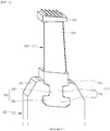
- FIG. 1 illustrates a portion of a rotating unit in a contemporary steam turbine.
- a rotating unit includes a rotatable rotor 200, and a bucket 300 coupled to the rotor 200 to convert the energy of steam injected from a nozzle (not shown) into mechanical work.
- the bucket 300 is twisted at a predetermined angle and is coupled to the rotor 200 to suppress vibration and prevent a leakage of steam, as disclosed in Japanese Patent Application Publication No. 2015-72017 .
- the bucket 300 consists of a plurality of buckets, and each of the buckets includes a root 310 coupled to the rotor 200, a blade 320 protruding in the radial direction of the rotor 200 from the root 310, and a cover 330 protruding in the rotational direction of the rotor 200 from the blade tip of the blade 320.
- the root 310 of one of the plurality of buckets 300 is supported by the rotor 200, and the cover 330 of the bucket 300 is pressure-welded to a cover 330 formed on a bucket 300 adjacent to the bucket 300, so that the blade 320 of each bucket 300 is twisted at a predetermined angle.
- the cover 330 of the bucket 300 overlaps the cover 330 of an adjacent bucket 300, and the adjacent covers 330 are pressure-welded to each other while the bucket 300 is twisted when it is coupled to the rotor 200.
- the related art rotating unit and the steam turbine including the same is problematic in that the twisting of the bucket 300 is released (untwisted) since the bucket 300 is not supported by the rotor 200 during operation.
- the root 310 includes a platform 312 formed at the blade root of the blade 320, and a dovetail protrusion 318 located opposite the blade 320 with respect to the platform 312.
- the dovetail protrusion 318 includes a first dovetail protrusion 314 that extends toward the center of rotation of the rotor 200 from the platform 312, and a second dovetail protrusion 316 that extends in the axial direction of the rotor 200 from the first dovetail protrusion 314.
- the dovetail protrusion 318 has a "T" shape for a reduction in cost of manufacture through shape simplification, and the "T" shape of the dovetail protrusion 318 is generally configured by extending toward a center of rotation of the rotor 200 from the platform 312.
- the rotor 200 coupled to the root 310 includes a seating groove 210 in which the platform 312 is seated, and a dovetail groove 240 that has a first dovetail groove 220 engaged with the first dovetail protrusion 314 and a second dovetail groove 230 engaged with the second dovetail protrusion 316.
- the bucket 300 may be twisted at a predetermined angle only when the dovetail protrusion 318 is supported by the dovetail groove 240.
- the pressure welding of the cover 330 enables the twisted state the blade 320 to persist as long as the first dovetail protrusion 314 remains pressure-welded in the axial direction of the rotor 200 by the first dovetail groove 220 and the second dovetail protrusion 316 remains pressure-welded in the axial direction of the rotor 200 by the second dovetail groove 230.
- the dovetail groove 240 is splayed in the axial direction of the rotor 200 by centrifugal force.
- the pressure welding of the first dovetail protrusion 314 in the axial direction of the rotor 200 by the first dovetail groove 220 is released, and the pressure welding of the second dovetail protrusion 316 in the axial direction of the rotor 200 by the second dovetail groove 230 is released. That is, the twisting of the bucket 300 is released, since the dovetail protrusion 318 is not supported by the dovetail groove 240 and the reaction caused by the twisting of the bucket 300 does not act on the root 310 of the bucket 300. Hence, vibration occurring during operation is increased.
- An object of the present invention is to provide a rotating unit capable of maintaining the twisting of a bucket even during operation, and a steam turbine including the same.
- a rotating unit may include a rotor; a bucket coupled to the rotor to convert fluid energy into mechanical work, the coupled bucket being pre-twisted at a predetermined angle, the bucket having a base surface facing a point of coupling between the rotor and the bucket; and bucket support means, provided at the point of coupling between the rotor and the bucket, for supporting a twisted state of the bucket based on the coupling between the rotor and the bucket.
- the bucket support means may include a keyway recessed in the base surface of the bucket, and a key inserted into the keyway.
- the bucket may be one of a plurality of buckets, and each bucket may include a root coupled to the rotor and supported by at least one of the rotor and the bucket support means; a blade protruding, in a radial direction of the rotor, from the root to a blade tip of the blade; and a cover protruding, in a rotational direction of the rotor, from the blade tip to a cover of an adjacent bucket of the plurality of buckets, the adjacent covers being pressure-welded to each other to fix the predetermined angle of the twisting of the blade of the bucket.
- the root may include a platform formed at a blade root of the blade, and a dovetail protrusion extending toward a center of rotation of the rotor from the platform, and the rotor may include a seating groove in which the platform is seated, and a dovetail groove engaged with the dovetail protrusion of the root.
- the bucket support means may be formed between the base surface of the second dovetail protrusion and the base surface of the second dovetail groove.
- the bucket support means may include a keyway recessed in the base surface of the second dovetail protrusion, and a key inserted into the keyway.
- a pressure welding of the first dovetail protrusion in the axial direction of the rotor by the first dovetail groove may be released, and a pressure welding of the second dovetail protrusion in the axial direction of the rotor by the second dovetail groove may be released, but the second dovetail protrusion remains pressure-welded in the axial direction of the rotor by the bucket support means.
- the key may be formed separately from the rotor and the bucket and may be made of a material different from the bucket, which may be a material having higher strength and a higher coefficient of thermal expansion than the bucket.
- the keyway and the key may extend in the rotational direction of the rotor.
- the keyway of one of the plurality of buckets may communicate with a keyway of an adjacent bucket, and the key may have a length in a rotational direction of the rotor that is longer than the keyway such that the key engages with at least two of the plurality of buckets.
- the keyway may have a width that is reduced as the keyway approaches the center of rotation of the rotor, and the key may engage with the keyway when inserted.
- the bucket support means may further include an auxiliary keyway recessed in the base surface of the bucket, and the key may include a first insertion portion inserted into the keyway and a second insertion portion inserted into the auxiliary keyway while protruding from the first insertion portion.
- the auxiliary keyway may have a width that is increased as the auxiliary keyway approaches the center of rotation of the rotor, and the second insertion portion of the key may engage with the auxiliary keyway when inserted.
- the rotating unit and a steam turbine of the present invention may further provide means to prevent the splaying of the dovetail groove during operation, to more effectively maintain the twisting of the bucket, which is in addition to the bucket support means.
- the root may include a platform formed at a blade root of the blade, and a dovetail protrusion having a first dovetail protrusion extending to a center of rotation of the rotor from the platform and a second dovetail protrusion surface extending in an axial direction of the rotor from the first dovetail protrusion, the second dovetail protrusion surface forming an acute angle with the first dovetail protrusion
- the rotor may include a seating groove to which the platform is seated, and a dovetail groove having a first dovetail groove engaged with the first dovetail protrusion and a second dovetail groove surface engaged with the second dovetail protrusion surface.
- a distance between the second dovetail protrusion surface and the center of rotation of the rotor increases with an increasing distance of the second dovetail protrusion surface from the first dovetail protrusion.
- a rib may protrude from an outer peripheral surface of the rotor and extend in the radial direction of the rotor over a region of the seating groove and the dovetail groove.
- a steam turbine may include a casing; the above-described rotating unit rotatably provided in the casing; and a nozzle for injecting steam into the rotating unit.
- a rotating unit of a steam turbine includes a rotor; a bucket coupled to the rotor to convert fluid energy into mechanical work, the coupled bucket being pre-twisted at a predetermined angle, the bucket having a base surface facing a point of coupling between the rotor and the bucket; and bucket support means, provided at the point of coupling between the rotor and the bucket, for supporting a twisted state of the bucket based on the coupling between the rotor and the bucket, wherein the bucket support means may include a keyway recessed in the base surface of the bucket, and a key inserted into the keyway, thereby enabling the twisting of the bucket to be maintained during operation.
- the bucket support means may include a keyway recessed in the base surface of the bucket, and a key inserted into the keyway, thereby enabling the twisting of the bucket to be maintained during operation.
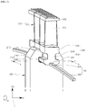
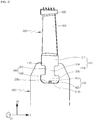
- FIGS. 2 and 3 illustrate a portion of a rotating unit in a steam turbine according to an embodiment of the present invention.
- the steam turbine may include a casing (not shown) that forms the external appearance and frame thereof, a rotating unit that is rotatably installed in the casing, and a nozzle (not shown) that injects steam into the rotating unit.
- the rotating unit may include a rotatable rotor 200, which may have a disk shape, and a bucket 300 coupled to the rotor 200 to convert the energy of steam injected from the nozzle into mechanical work.
- the rotary shaft (not shown) of the rotor 200 passes through the center (not shown) of the rotor 200.
- the rotor 200 may have a seating groove 210 and a dovetail groove 240, which are formed in the outer peripheral portion thereof, such that the rotor 200 is coupled with the bucket 300.
- the coupling is achieved by seating a platform 312 (to be described later) of the bucket 300 in the seating groove 210 and by engaging a dovetail protrusion 318 (to be described later) of the bucket 300 with the dovetail groove 240. Pressure welding (to be described later) completes the coupling.
- the seating groove 210 may be recessed from an outer peripheral surface of the rotor 200 toward the center of rotation of the rotor 200 in the radial direction of the rotor 200.
- the dovetail groove 240 may be further recessed from the seating groove 210 toward the center of rotation of the rotor 200 in the radial direction of the rotor 200.
- the dovetail groove 240 may include a first dovetail groove 220 that has a shape corresponding to a first dovetail protrusion 314 (to be described later) of the dovetail protrusion 318 and engages with the first dovetail protrusion 314, and a second dovetail groove 230 that has a shape corresponding to a second dovetail protrusion 316 (to be described later) of the dovetail protrusion 318 and engages with the second dovetail protrusion 316.
- the seating groove 210 and the dovetail groove 240 may extend in the rotational direction of the rotor 200 such that the bucket 300 is inserted into and is coupled to the rotor 200 in the rotational direction of the rotor 200.
- the axial direction of the rotor 200 will be referred to as a first direction D1
- the rotational direction of the rotor 200 will be referred to as a second direction D2
- the radial direction of the rotor 200 will be referred to as a third direction D3.
- the indicated axial or radial "direction" may be assumed to be either of opposite directions along a corresponding line
- the indicated rotational "direction” may be assumed to be either of opposite rotational directions.
- the bucket 300 may consist of a plurality of buckets.
- the bucket 300 of the drawings is one of the plurality of buckets 300, which may be arranged adjacent to each other in the second direction D2.
- Each of the buckets 300 may include a root 310 coupled to the rotor 200, a blade 320 protruding in the third direction D3 (more precisely, in the centrifugal direction of the rotor 200) from the root 310, and a cover 330 protruding bidirectionally along the second direction D2 from the blade tip of the blade 320.
- the blade tip forms the end of the blade 320 opposite from the root 310.
- the root 310 may include a platform 312 formed at the blade root of the blade 320, and a dovetail protrusion 318 located opposite the blade 320 with respect to the platform 312.
- the blade root forms the base of the blade 320 opposite from the blade tip.
- the first direction length of the platform 312 may be shorter than the first direction length of the rotor such that the platform 312 is inserted into the seating groove 210 of the rotor
- the second direction length of the platform may be shorter than the second direction length of the cover 330 such that the cover 330 is pressure-welded to another cover 330 by overlapping therewith
- the third direction length of the platform may be longer than the third direction depth of the seating groove 210 such that the blade 320 protrudes outward of the seating groove 210.
- the dovetail protrusion 318 is engageable with the rotor 200, and may have a "T" shape for a reduction in cost of manufacture through shape simplification. That is, the dovetail protrusion 318 may include a first dovetail protrusion 314 that extends toward the center of rotation of the rotor 200 in the third direction D3 from the platform 312, and a second dovetail protrusion 316 that extends bidirectionally along the first direction D1 from the tip of the first dovetail protrusion 314.
- the first direction length of the first dovetail protrusion 314 may be shorter than the first direction length of the platform 312, the second direction length of the first dovetail protrusion 314 may be substantially equal to the second direction length of the platform 312, and the third direction length of the first dovetail protrusion 314 may be substantially equal to the third direction length of the platform 312.
- the first direction length of the second dovetail protrusion 316 may be longer than the first direction length of the platform 312 and the first direction length of the first dovetail protrusion 314, the second direction length of the second dovetail protrusion 316 may be substantially equal to the second direction length of the platform 312 and the second direction length of the first dovetail protrusion 314, and the third direction length of the second dovetail protrusion 316 may be substantially equal to the third direction length of the platform 312 and the third direction length of the first dovetail protrusion 314.
- the platform 312 and the dovetail protrusion 318 may extend in the second direction D2 such that the bucket 300 is inserted into and coupled to the rotor 200 in the second direction D2.
- the blade 320 may have an airfoil profile in which a blade back and a blade belly are located on opposite sides of the blade 320 along the second direction D2.
- the cover 330 may be configured such that a cover 330 of a sample bucket 300 of the plurality of buckets 300 is pressure-welded to a cover 330 formed on a bucket 300 adjacent to the sample bucket 300.
- Each cover 330 is configured to have a second direction length that is longer than a reference length, where the reference length is the length of an arc obtained by dividing the circumference of a circle having a known radius by the number of buckets.
- the radius of the circle is set as the distance between the rotary shaft of the rotor 200 and the cover 330.
- these covers 330 may be pressure-welded to each other by overlapping and tilting when the buckets 300 are coupled to the rotor 200.
- the rotating unit may be configured such that the bucket 300 is twisted at a predetermined angle and is then coupled to the rotor 200 to suppress vibration and prevent a leakage of steam. That is, the root 310 of one of the plurality of buckets 300 is supported by the rotor 200 and the cover 330 of the bucket 300 is pressure-welded to the cover 330 of an adjacent bucket 300, thereby enabling the blade 320 of the bucket 300 to be twisted at a predetermined angle.
- the bucket 300 may be configured such that, when the root 310 is fixedly supported at the time when the cover 330 is pressure-welded to another cover 330, the blade 320 is twisted. That is, when the first dovetail protrusion 314 is pressure-welded in the first direction D1 by the first dovetail groove 220 and the second dovetail protrusion 316 is pressure-welded in the first direction D1 by the second dovetail groove 230, the blade 320 may be twisted by the pressure welding of the cover 330.
- the twisting of the bucket can affect the natural frequency of the rotating unit to reduce vibration, and it is possible to enhance the efficiency of the steam turbine by the tight contact between the cover 330 and another cover 330 to prevent a leakage of steam due to the gap therebetween.
- the twisting of the bucket 300 may be released during operation. That is, the root 310 is well supported by the rotor 200 when the rotational speed of the rotating unit is kept below a predetermined speed, to include a stopped state of the rotating unit, but the root 310 may not be well supported by the rotor 200 when the rotating unit exceeds the predetermined speed such that the dovetail groove 240 is splayed in the first direction D1 by centrifugal force.
- the rotating unit may further include a bucket support means 400 for supporting the bucket 300 at a coupling portion between the rotor 200 and the bucket 300 and for supporting a twisted state of the bucket 300 based on the coupling between the rotor 200 and the bucket 300.
- the bucket support means 400 may include a keyway 410 recessed in a base surface 316a of the second dovetail protrusion 316, and a key 420 inserted into the keyway 410.
- the base surface 316a is provided to the bucket 300 at the coupling portion and faces a point of coupling between the rotor 200 and the bucket 300.
- the bucket support means 400 may be formed, at the coupling portion, between the base surface 316a of the second dovetail protrusion 316 of the dovetail protrusion 318 and a base surface 230a of the second dovetail groove 230 of the dovetail groove 240, so as to prevent the key 420 from being separated from the keyway 410 by centrifugal force.
- the base surface 316a of the second dovetail protrusion 316 is a surface facing the center of rotation of the rotor 200
- the base surface 230a of the second dovetail groove 230 is a surface facing the base surface 316a of the second dovetail protrusion 316.
- the bucket support means 400 may be formed at the center of the base surface 316a of the second dovetail protrusion 316 of the dovetail protrusion 318 and the center of the base surface 230a of the second dovetail groove 230 of the dovetail groove 240 in order to prevent the bucket support means 400 from adversely affecting the rotational balance of the rotating unit.
- the key 420 may be formed separately from the rotor 200 and the bucket 300 to more stably support the bucket 300 and prevent damage to the key 420.
- the key 420 may be formed integrally with the rotor 200. That is, a protrusion in the shape of key 420 may be formed to protrude from the base surface 230a of the second dovetail groove 230 toward the keyway 410, to reduce manufacturing costs associated with a separate manufacture and assembly of the key 420.
- the integrally formed key 420 may be easily damaged. That is, since the torsional reaction of the bucket 300 and the centrifugal force of the rotating unit are concentrated on a relatively small device, i.e., the key 420 or the above key-shaped protrusion, it is difficult to improve the stiffness of a key 420 formed integrally with the rotor 200.
- the key 420 When, as in the present embodiment, the key 420 is formed separately from the rotor 200 and the bucket 300, the key 420 may be made of a material having higher strength than the rotor 200 and the bucket 300. Therefore, it is possible to prevent damage to the key 420.
- the key 420 when the key 420 is formed separately from the rotor 200 and the bucket 300, the key 420 may be made of a material having a higher coefficient of thermal expansion than the bucket 300.
- the key 420 since the key 420 is more strongly pressure-welded to the keyway 410 when the rotating unit is thermally expanded by heat generated during operation, it is possible to more stably support the twisting of the bucket 300.
- the key 420 when the key 420 is formed separately from the rotor 200 and the bucket 300, the key 420 may be configured such that the second direction length thereof differs from the second direction length of the keyway 410. That is, the keyway 410 and the key 420 extend in the second direction D2, in which case the keyway 410 formed in one of the plurality of buckets 300 may communicate with a keyway 410 formed in a bucket 300 adjacent to the bucket 300 and the second direction length of the key 420 may be longer than the second direction length of the keyway 410 such that the key 420 is engaged with at least two of the plurality of buckets 300.
- a plurality of keyways 410 simultaneously engaged with the same key 420 may be affected by one another through a single key 420, thereby causing the key 420 to provide a stronger reaction to the plurality of buckets 300 supported by the key 420. Therefore, it is possible to more stably support the twisted state of the plurality of buckets 300. Besides, it is possible to prevent the key 420 from rotating relative to the rotor 200 and the bucket 300 when the rotating unit rotates.
- the steam injected from the nozzle may be introduced into the bucket 300 in the first direction D1, and the steam introduced into the bucket 300 may pass through the bucket 300 while the direction of flow of the steam is changed by the bucket 300.
- impulsive force may act on the bucket 300 by the steam, so that the bucket 300 may convert the energy of steam into mechanical work while rotating in the second direction D2 together with the rotor 200.
- the rotating unit according to the present embodiment since the bucket 300 is twisted at the predetermined angle and then coupled to the rotor 200, the natural frequency of the rotating unit is changed to suppress vibration and prevent a leakage of steam between adjacent covers 330. Therefore, it is possible to enhance energy efficiency.
- the rotating unit further includes the bucket support means 400, the twisting of the bucket 300 may be maintained even during operation. That is, provided that the rotational speed of the rotating unit does not exceed the predetermined speed, the first dovetail protrusion 314 may be pressure-welded in the first direction D1 by the first dovetail groove 220 and the second dovetail protrusion 316 may be pressure-welded in the first direction D1 by the second dovetail groove 230 and the bucket support means 400.
- the dovetail groove 240 is splayed in the first direction D1 so that the pressure welding of the first dovetail protrusion 314 in the first direction D1 by the first dovetail groove 220 is released and the pressure welding of the second dovetail protrusion 316 in the first direction D1 by the second dovetail groove 230 is released.
- the second dovetail protrusion 316 of the dovetail protrusion 318 may still be pressure-welded in the first direction D1 by the bucket support means 400.
- the keyway 410 and the key 420 have a uniform first direction length (width) in the present embodiment, they may have a variable first direction length as in an embodiment illustrated in FIG. 4 . That is, the first direction length of the keyway 410 may be reduced as the keyway 410 approaches the center of rotation of the rotor 200, or as the keyway 410 approaches the base surface 230a, in the third direction D3.
- the key 420 may have a shape corresponding to the shape of the keyway 410 so as to be engaged to the keyway 410. That is, the first direction length of the key 420 may likewise be reduced as the key 420 approaches the center of rotation of the rotor 200, or as the key 420 approaches the base surface 316a, in the third direction D3. In this case, the effect of this embodiment may be substantially the same as that of the above embodiment. However, since the opening of the keyway 410 is relatively small in this case, it is possible to previously prevent the separation of the key 420 from the keyway 410 during operation.
- the key 420 may also be inserted into the rotor 200 as in an embodiment illustrated in FIG. 5 . That is, the bucket support means 400 may further include an auxiliary keyway 430 recessed to the center of rotation of the rotor 200 in the third direction D3 from the base surface 230a of the second dovetail groove 230.
- the key 420 may include a first insertion portion 422 that is inserted into the keyway 410, and a second insertion portion 424 that protruding toward the center of rotation of the rotor 200 in the third direction D3 from the first insertion portion 422 and is inserted into the auxiliary keyway 430.
- the auxiliary keyway 430 and the second insertion portion 424 may extend in the second direction D2.
- the effect of this embodiment may be substantially the same as that of the above embodiment.
- the bucket 300 is coupled to the rotor 200 and the key 420 in the state in which the position of the key 420 is guided by the auxiliary keyway 430 when the key 420 is assembled to the rotating unit, it is possible to easily assembly the rotating unit.
- the key 420 is simultaneously supported by the keyway 410 and the auxiliary keyway 430, it is possible to more effectively prevent the key 420 from rotating relative to the rotor 200 and the bucket 300 during operation and to more stably support the bucket 300.
- the keyway 410 and the first insertion portion 422 of the key 420 may be formed as in the embodiment of FIG. 4 and the auxiliary keyway 430 and the second insertion portion 424 of the key 420 may be formed similarly to the keyway 410 and the first insertion portion 422 of the key 420.
- the first direction length of the keyway 410 may be reduced as the keyway 410 approaches the center of rotation of the rotor 200 in the third direction D3.
- the first insertion portion 422 of the key 420 may have a shape corresponding to the shape of the keyway 410 so as to engage with the keyway 410. That is, the first direction length of the first insertion portion 422 of the key 420 may be reduced as the first insertion portion 422 approaches the center of rotation of the rotor 200 in the third direction D3.
- the first direction length of the auxiliary keyway 430 may be increased as the auxiliary keyway 430 approaches the center of rotation of the rotor 200 in the third direction D3.
- the second insertion portion 424 of the key 420 may have a shape corresponding to the shape of the auxiliary keyway 430 so as to engage with the auxiliary keyway 430. That is, the first direction length of the second insertion portion 424 of the key 420 may be increased as the second insertion portion 424 approaches the center of rotation of the rotor 200 in the third direction D3.
- the effect of this embodiment may be substantially the same as that of the above embodiment.
- the opening of the auxiliary keyway 430 is relatively small in this case, it is possible to previously prevent the separation of the key 420 from the keyway 410 and the auxiliary keyway 430 during operation.
- the movement of the bucket 300 in the third direction D3 is suppressed during operation by the second insertion portion 424 serving to prevent the separation of the key 420 from the auxiliary keyway 430 in the third direction D3, thereby reducing the force of the bucket 300 applied to the dovetail groove 240 of the rotor 200.
- the second insertion portion 424 serving to prevent the separation of the key 420 from the auxiliary keyway 430 in the third direction D3, thereby reducing the force of the bucket 300 applied to the dovetail groove 240 of the rotor 200.
- the rotating unit may also include a dovetail groove splaying prevention means as in an embodiment illustrated in FIGS. 6 and 7 .
- the dovetail groove splaying prevention means prevents the splaying of the dovetail groove 240 during operation, to more effectively maintain the twisting of the bucket 300.
- the second dovetail protrusion 316 may include a second dovetail protrusion surface 316b that forms an acute angle with the first dovetail protrusion 314, and the second dovetail groove 230 may include a second dovetail groove surface 230b that forms a complementary angle to engage with the second dovetail protrusion surface 316b.
- the second dovetail protrusion surface 316b and the second dovetail groove surface 230b overlap in the first direction D1.
- the third direction distance between the second dovetail protrusion surface 316b and the center of rotation of the rotor 200 may increase with an increasing distance of the second dovetail protrusion surface 316b from the first dovetail protrusion 314 in the first direction D1, and the second dovetail groove surface 230b and the second dovetail protrusion surface 316b have corresponding and complementary shapes with respect to each other. That is, the third direction distance between the second dovetail groove surface 230b and the center of rotation of the rotor 200 may likewise increase with an increasing distance of the second dovetail groove surface 230b from the first dovetail protrusion 314 in the first direction D1.
- the second dovetail protrusion surface 316b prevents the second dovetail groove surface 230b from moving away from the bucket 300 in the first direction D1. As a result, it is possible to prevent the splaying of the dovetail groove 220/230 during operation.
- the rotor 200 may have a rib 250 protruding from the outer peripheral surface of the rotor 200, and the rib 250 may extend in the third direction D3 over an outer peripheral portion of the rotor 200 that is structurally adjacent to the region of the seating groove 210 and the dovetail groove 240. Since the rib 250 serves to enhance the stiffness of the outer peripheral portion of the rotor 200 forming the dovetail groove 240, it is possible to prevent the splaying of the dovetail groove 240.
- the root 310 of the bucket 300 is pressure-welded in the first direction D1 by the rotor 200 as well as the key 420. Therefore, it is possible to more securely support the root 310 and more effectively maintain the twisting of the bucket 300.
Landscapes
- Engineering & Computer Science (AREA)
- Mechanical Engineering (AREA)
- General Engineering & Computer Science (AREA)
- Turbine Rotor Nozzle Sealing (AREA)
Abstract
Description
- This application claims priority to Korean Patent Application No(s).
10-2017-0042044, filed on March 31, 2017 - Exemplary embodiments of the present invention relate to a rotating unit and a steam turbine including the same, and more particularly, to a rotating unit in which a pre-twisted type continuous coupled bucket (CCB) structure is applied for a turbine wheel, and to a steam turbine including the same. In the rotating unit of the present invention, a bucket is inserted into a rotor in the rotational direction and is then coupled to the rotor in a state in which the bucket is twisted at a predetermined angle.
- In general, a turbine is a machine that converts the energy of a fluid such as water, gas, or steam into mechanical work, and a turbomachine, in which many vanes or blades are mounted to the circumference of a rotating unit and steam or gas is injected into the blades to rotate the rotating unit at high speed, is typically referred to as the turbine. Examples of the turbine include a water turbine using the energy of falling water, a steam turbine using the energy of steam, a gas turbine using the energy of high-temperature and high-pressure gas, and an air turbine using the energy of high-pressure compressed air.
- Among these, the steam turbine rotates a rotating unit by injecting steam from a nozzle toward a plurality of blades to convert the energy of the steam into mechanical work. Specifically, the steam turbine includes a casing that forms the turbine's external appearance and frame, a rotating unit that is rotatably installed in the casing, and a nozzle that injects steam into the rotating unit.
-
FIG. 1 illustrates a portion of a rotating unit in a contemporary steam turbine. - Referring to
FIG. 1 , a rotating unit includes arotatable rotor 200, and abucket 300 coupled to therotor 200 to convert the energy of steam injected from a nozzle (not shown) into mechanical work. - The
bucket 300 is twisted at a predetermined angle and is coupled to therotor 200 to suppress vibration and prevent a leakage of steam, as disclosed in Japanese Patent Application Publication No.2015-72017 - In more detail, the
bucket 300 consists of a plurality of buckets, and each of the buckets includes aroot 310 coupled to therotor 200, ablade 320 protruding in the radial direction of therotor 200 from theroot 310, and acover 330 protruding in the rotational direction of therotor 200 from the blade tip of theblade 320. Theroot 310 of one of the plurality ofbuckets 300 is supported by therotor 200, and thecover 330 of thebucket 300 is pressure-welded to acover 330 formed on abucket 300 adjacent to thebucket 300, so that theblade 320 of eachbucket 300 is twisted at a predetermined angle. Here, thecover 330 of thebucket 300 overlaps thecover 330 of anadjacent bucket 300, and theadjacent covers 330 are pressure-welded to each other while thebucket 300 is twisted when it is coupled to therotor 200. - However, the related art rotating unit and the steam turbine including the same is problematic in that the twisting of the
bucket 300 is released (untwisted) since thebucket 300 is not supported by therotor 200 during operation. - Specifically, the
root 310 includes aplatform 312 formed at the blade root of theblade 320, and adovetail protrusion 318 located opposite theblade 320 with respect to theplatform 312. Thedovetail protrusion 318 includes afirst dovetail protrusion 314 that extends toward the center of rotation of therotor 200 from theplatform 312, and asecond dovetail protrusion 316 that extends in the axial direction of therotor 200 from thefirst dovetail protrusion 314. Here, thedovetail protrusion 318 has a "T" shape for a reduction in cost of manufacture through shape simplification, and the "T" shape of thedovetail protrusion 318 is generally configured by extending toward a center of rotation of therotor 200 from theplatform 312. - Meanwhile, the
rotor 200 coupled to theroot 310 includes aseating groove 210 in which theplatform 312 is seated, and adovetail groove 240 that has afirst dovetail groove 220 engaged with thefirst dovetail protrusion 314 and asecond dovetail groove 230 engaged with thesecond dovetail protrusion 316. In this case, thebucket 300 may be twisted at a predetermined angle only when thedovetail protrusion 318 is supported by thedovetail groove 240. That is, the pressure welding of thecover 330 enables the twisted state theblade 320 to persist as long as thefirst dovetail protrusion 314 remains pressure-welded in the axial direction of therotor 200 by thefirst dovetail groove 220 and thesecond dovetail protrusion 316 remains pressure-welded in the axial direction of therotor 200 by thesecond dovetail groove 230. - However, in the related art, if the rotation of the rotating unit exceeds a predetermined speed, the
dovetail groove 240 is splayed in the axial direction of therotor 200 by centrifugal force. Thereby, the pressure welding of thefirst dovetail protrusion 314 in the axial direction of therotor 200 by thefirst dovetail groove 220 is released, and the pressure welding of thesecond dovetail protrusion 316 in the axial direction of therotor 200 by thesecond dovetail groove 230 is released. That is, the twisting of thebucket 300 is released, since thedovetail protrusion 318 is not supported by thedovetail groove 240 and the reaction caused by the twisting of thebucket 300 does not act on theroot 310 of thebucket 300. Hence, vibration occurring during operation is increased. In addition, steam leaks between the adjacent covers 330 due to a reduction in contact force between thecovers 330. - An object of the present invention is to provide a rotating unit capable of maintaining the twisting of a bucket even during operation, and a steam turbine including the same.
- Other objects and advantages of the present invention can be understood by the following description, and become apparent with reference to the embodiments of the present invention. Also, it is obvious to those skilled in the art to which the present invention pertains that the objects and advantages of the present invention can be realized by the means as claimed and combinations thereof.
- In accordance with one aspect of the present invention, a rotating unit may include a rotor; a bucket coupled to the rotor to convert fluid energy into mechanical work, the coupled bucket being pre-twisted at a predetermined angle, the bucket having a base surface facing a point of coupling between the rotor and the bucket; and bucket support means, provided at the point of coupling between the rotor and the bucket, for supporting a twisted state of the bucket based on the coupling between the rotor and the bucket.
- The bucket support means may include a keyway recessed in the base surface of the bucket, and a key inserted into the keyway.
- The bucket may be one of a plurality of buckets, and each bucket may include a root coupled to the rotor and supported by at least one of the rotor and the bucket support means; a blade protruding, in a radial direction of the rotor, from the root to a blade tip of the blade; and a cover protruding, in a rotational direction of the rotor, from the blade tip to a cover of an adjacent bucket of the plurality of buckets, the adjacent covers being pressure-welded to each other to fix the predetermined angle of the twisting of the blade of the bucket.
- The root may include a platform formed at a blade root of the blade, and a dovetail protrusion extending toward a center of rotation of the rotor from the platform, and the rotor may include a seating groove in which the platform is seated, and a dovetail groove engaged with the dovetail protrusion of the root. Assuming that the surface facing the center of rotation of the rotor in the second dovetail protrusion is a base surface of the second dovetail protrusion and the surface facing the base surface of the second dovetail protrusion in the second dovetail groove is a base surface of the second dovetail groove, the bucket support means may be formed between the base surface of the second dovetail protrusion and the base surface of the second dovetail groove. In this case, the bucket support means may include a keyway recessed in the base surface of the second dovetail protrusion, and a key inserted into the keyway.
- When the rotating unit exceeds a predetermined speed, a pressure welding of the first dovetail protrusion in the axial direction of the rotor by the first dovetail groove may be released, and a pressure welding of the second dovetail protrusion in the axial direction of the rotor by the second dovetail groove may be released, but the second dovetail protrusion remains pressure-welded in the axial direction of the rotor by the bucket support means.
- The key may be formed separately from the rotor and the bucket and may be made of a material different from the bucket, which may be a material having higher strength and a higher coefficient of thermal expansion than the bucket.
- The keyway and the key may extend in the rotational direction of the rotor. Thus, when the bucket is one of a plurality of buckets, the keyway of one of the plurality of buckets may communicate with a keyway of an adjacent bucket, and the key may have a length in a rotational direction of the rotor that is longer than the keyway such that the key engages with at least two of the plurality of buckets.
- The keyway may have a width that is reduced as the keyway approaches the center of rotation of the rotor, and the key may engage with the keyway when inserted.
- The bucket support means may further include an auxiliary keyway recessed in the base surface of the bucket, and the key may include a first insertion portion inserted into the keyway and a second insertion portion inserted into the auxiliary keyway while protruding from the first insertion portion. The auxiliary keyway may have a width that is increased as the auxiliary keyway approaches the center of rotation of the rotor, and the second insertion portion of the key may engage with the auxiliary keyway when inserted.
- The rotating unit and a steam turbine of the present invention may further provide means to prevent the splaying of the dovetail groove during operation, to more effectively maintain the twisting of the bucket, which is in addition to the bucket support means. Here, the root may include a platform formed at a blade root of the blade, and a dovetail protrusion having a first dovetail protrusion extending to a center of rotation of the rotor from the platform and a second dovetail protrusion surface extending in an axial direction of the rotor from the first dovetail protrusion, the second dovetail protrusion surface forming an acute angle with the first dovetail protrusion, and the rotor may include a seating groove to which the platform is seated, and a dovetail groove having a first dovetail groove engaged with the first dovetail protrusion and a second dovetail groove surface engaged with the second dovetail protrusion surface. In this configuration, a distance between the second dovetail protrusion surface and the center of rotation of the rotor increases with an increasing distance of the second dovetail protrusion surface from the first dovetail protrusion. Also, a rib may protrude from an outer peripheral surface of the rotor and extend in the radial direction of the rotor over a region of the seating groove and the dovetail groove.
- In accordance with another aspect of the present invention, a steam turbine may include a casing; the above-described rotating unit rotatably provided in the casing; and a nozzle for injecting steam into the rotating unit.
- As is apparent from the above description, the present invention provides a rotating unit and a steam turbine including the same. A rotating unit of a steam turbine includes a rotor; a bucket coupled to the rotor to convert fluid energy into mechanical work, the coupled bucket being pre-twisted at a predetermined angle, the bucket having a base surface facing a point of coupling between the rotor and the bucket; and bucket support means, provided at the point of coupling between the rotor and the bucket, for supporting a twisted state of the bucket based on the coupling between the rotor and the bucket, wherein the bucket support means may include a keyway recessed in the base surface of the bucket, and a key inserted into the keyway, thereby enabling the twisting of the bucket to be maintained during operation. Thus, it is possible to reduce vibration occurring during operation and increase the contact force between a cover formed at the blade tip of the bucket and a cover of another bucket to prevent a leakage of steam between adjacent covers.
- It is to be understood that both the foregoing general description and the following detailed description of the present invention are exemplary and explanatory and are intended to provide further explanation of the invention as claimed.
- The above and other objects, features and other advantages of the present invention will be more clearly understood from the following detailed description taken in conjunction with the accompanying drawings, in which:
-
FIG. 1 is a perspective view illustrating a portion of a rotating unit in a contemporary steam turbine; -
FIG. 2 is a perspective view illustrating a portion of a rotating unit in a steam turbine according to a first embodiment of the present invention; -
FIG. 3 is a cross-sectional view taken along line A-A ofFIG. 2 ; -
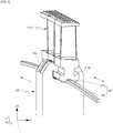
FIG. 4 is a cross-sectional view illustrating a portion of a rotating unit in a steam turbine according to a second embodiment of the present invention; -
FIG. 5 is a cross-sectional view illustrating a portion of a rotating unit in a steam turbine according to still a third embodiment of the present invention; -
FIG. 6 is a perspective view illustrating a portion of a rotating unit in a steam turbine according to a fourth embodiment of the present invention; and -
FIG. 7 is a cross-sectional view taken along line B-B ofFIG. 6 . - Reference will now be made in detail to exemplary embodiments of the present invention, examples of which are illustrated in the accompanying drawings. The present invention may, however, be embodied in different forms and should not be construed as limited to the embodiments set forth herein. Rather, these embodiments are provided so that this disclosure will be thorough and complete, and will fully convey the scope of the present invention to those skilled in the art. Throughout the disclosure, like reference numerals refer to like parts throughout the various figures and embodiments of the present invention.
- Hereinafter, a rotating unit and a steam turbine including the same according to exemplary embodiments of the present invention will be described in detail with reference to the accompanying drawings.
-
FIGS. 2 and3 illustrate a portion of a rotating unit in a steam turbine according to an embodiment of the present invention. - Referring to
FIGS. 2 and3 , the steam turbine according to the embodiment of the present invention may include a casing (not shown) that forms the external appearance and frame thereof, a rotating unit that is rotatably installed in the casing, and a nozzle (not shown) that injects steam into the rotating unit. The rotating unit may include arotatable rotor 200, which may have a disk shape, and abucket 300 coupled to therotor 200 to convert the energy of steam injected from the nozzle into mechanical work. The rotary shaft (not shown) of therotor 200 passes through the center (not shown) of therotor 200. - The
rotor 200 may have aseating groove 210 and adovetail groove 240, which are formed in the outer peripheral portion thereof, such that therotor 200 is coupled with thebucket 300. The coupling is achieved by seating a platform 312 (to be described later) of thebucket 300 in theseating groove 210 and by engaging a dovetail protrusion 318 (to be described later) of thebucket 300 with thedovetail groove 240. Pressure welding (to be described later) completes the coupling. - The
seating groove 210 may be recessed from an outer peripheral surface of therotor 200 toward the center of rotation of therotor 200 in the radial direction of therotor 200. Thedovetail groove 240 may be further recessed from theseating groove 210 toward the center of rotation of therotor 200 in the radial direction of therotor 200. Thedovetail groove 240 may include afirst dovetail groove 220 that has a shape corresponding to a first dovetail protrusion 314 (to be described later) of thedovetail protrusion 318 and engages with thefirst dovetail protrusion 314, and asecond dovetail groove 230 that has a shape corresponding to a second dovetail protrusion 316 (to be described later) of thedovetail protrusion 318 and engages with thesecond dovetail protrusion 316. - The
seating groove 210 and thedovetail groove 240 may extend in the rotational direction of therotor 200 such that thebucket 300 is inserted into and is coupled to therotor 200 in the rotational direction of therotor 200. - For the sake of convenience, in the following description, the axial direction of the
rotor 200 will be referred to as a first direction D1, the rotational direction of therotor 200 will be referred to as a second direction D2, and the radial direction of therotor 200 will be referred to as a third direction D3. As the case may warrant, the indicated axial or radial "direction" may be assumed to be either of opposite directions along a corresponding line, and the indicated rotational "direction" may be assumed to be either of opposite rotational directions. - The
bucket 300 may consist of a plurality of buckets. In other words, thebucket 300 of the drawings is one of the plurality ofbuckets 300, which may be arranged adjacent to each other in the second direction D2. - Each of the
buckets 300 may include aroot 310 coupled to therotor 200, ablade 320 protruding in the third direction D3 (more precisely, in the centrifugal direction of the rotor 200) from theroot 310, and acover 330 protruding bidirectionally along the second direction D2 from the blade tip of theblade 320. Here, the blade tip forms the end of theblade 320 opposite from theroot 310. - The
root 310 may include aplatform 312 formed at the blade root of theblade 320, and adovetail protrusion 318 located opposite theblade 320 with respect to theplatform 312. Here, the blade root forms the base of theblade 320 opposite from the blade tip. - The first direction length of the
platform 312 may be shorter than the first direction length of the rotor such that theplatform 312 is inserted into theseating groove 210 of the rotor, the second direction length of the platform may be shorter than the second direction length of thecover 330 such that thecover 330 is pressure-welded to anothercover 330 by overlapping therewith, and the third direction length of the platform may be longer than the third direction depth of theseating groove 210 such that theblade 320 protrudes outward of theseating groove 210. - The
dovetail protrusion 318 is engageable with therotor 200, and may have a "T" shape for a reduction in cost of manufacture through shape simplification. That is, thedovetail protrusion 318 may include afirst dovetail protrusion 314 that extends toward the center of rotation of therotor 200 in the third direction D3 from theplatform 312, and asecond dovetail protrusion 316 that extends bidirectionally along the first direction D1 from the tip of thefirst dovetail protrusion 314. - The first direction length of the
first dovetail protrusion 314 may be shorter than the first direction length of theplatform 312, the second direction length of thefirst dovetail protrusion 314 may be substantially equal to the second direction length of theplatform 312, and the third direction length of thefirst dovetail protrusion 314 may be substantially equal to the third direction length of theplatform 312. - The first direction length of the
second dovetail protrusion 316 may be longer than the first direction length of theplatform 312 and the first direction length of thefirst dovetail protrusion 314, the second direction length of thesecond dovetail protrusion 316 may be substantially equal to the second direction length of theplatform 312 and the second direction length of thefirst dovetail protrusion 314, and the third direction length of thesecond dovetail protrusion 316 may be substantially equal to the third direction length of theplatform 312 and the third direction length of thefirst dovetail protrusion 314. - Meanwhile, the
platform 312 and thedovetail protrusion 318 may extend in the second direction D2 such that thebucket 300 is inserted into and coupled to therotor 200 in the second direction D2. - The
blade 320 may have an airfoil profile in which a blade back and a blade belly are located on opposite sides of theblade 320 along the second direction D2. - The
cover 330 may be configured such that acover 330 of asample bucket 300 of the plurality ofbuckets 300 is pressure-welded to acover 330 formed on abucket 300 adjacent to thesample bucket 300. Eachcover 330 is configured to have a second direction length that is longer than a reference length, where the reference length is the length of an arc obtained by dividing the circumference of a circle having a known radius by the number of buckets. Here, the radius of the circle is set as the distance between the rotary shaft of therotor 200 and thecover 330. Thus, thesecovers 330 may be pressure-welded to each other by overlapping and tilting when thebuckets 300 are coupled to therotor 200. - Here, the rotating unit may be configured such that the
bucket 300 is twisted at a predetermined angle and is then coupled to therotor 200 to suppress vibration and prevent a leakage of steam. That is, theroot 310 of one of the plurality ofbuckets 300 is supported by therotor 200 and thecover 330 of thebucket 300 is pressure-welded to thecover 330 of anadjacent bucket 300, thereby enabling theblade 320 of thebucket 300 to be twisted at a predetermined angle. - The
bucket 300 may be configured such that, when theroot 310 is fixedly supported at the time when thecover 330 is pressure-welded to anothercover 330, theblade 320 is twisted. That is, when thefirst dovetail protrusion 314 is pressure-welded in the first direction D1 by thefirst dovetail groove 220 and thesecond dovetail protrusion 316 is pressure-welded in the first direction D1 by thesecond dovetail groove 230, theblade 320 may be twisted by the pressure welding of thecover 330. The twisting of the bucket can affect the natural frequency of the rotating unit to reduce vibration, and it is possible to enhance the efficiency of the steam turbine by the tight contact between thecover 330 and anothercover 330 to prevent a leakage of steam due to the gap therebetween. - However, the twisting of the
bucket 300 may be released during operation. That is, theroot 310 is well supported by therotor 200 when the rotational speed of the rotating unit is kept below a predetermined speed, to include a stopped state of the rotating unit, but theroot 310 may not be well supported by therotor 200 when the rotating unit exceeds the predetermined speed such that thedovetail groove 240 is splayed in the first direction D1 by centrifugal force. - In view of this, the rotating unit according to the present embodiment may further include a bucket support means 400 for supporting the
bucket 300 at a coupling portion between therotor 200 and thebucket 300 and for supporting a twisted state of thebucket 300 based on the coupling between therotor 200 and thebucket 300. The bucket support means 400 may include akeyway 410 recessed in abase surface 316a of thesecond dovetail protrusion 316, and a key 420 inserted into thekeyway 410. Thus, thebase surface 316a is provided to thebucket 300 at the coupling portion and faces a point of coupling between therotor 200 and thebucket 300. - The bucket support means 400 may be formed, at the coupling portion, between the
base surface 316a of thesecond dovetail protrusion 316 of thedovetail protrusion 318 and abase surface 230a of thesecond dovetail groove 230 of thedovetail groove 240, so as to prevent the key 420 from being separated from thekeyway 410 by centrifugal force. In this case, thebase surface 316a of thesecond dovetail protrusion 316 is a surface facing the center of rotation of therotor 200, and thebase surface 230a of thesecond dovetail groove 230 is a surface facing thebase surface 316a of thesecond dovetail protrusion 316. - The bucket support means 400 may be formed at the center of the
base surface 316a of thesecond dovetail protrusion 316 of thedovetail protrusion 318 and the center of thebase surface 230a of thesecond dovetail groove 230 of thedovetail groove 240 in order to prevent the bucket support means 400 from adversely affecting the rotational balance of the rotating unit. - Meanwhile, according to the present embodiment, the key 420 may be formed separately from the
rotor 200 and thebucket 300 to more stably support thebucket 300 and prevent damage to the key 420. - Alternatively, the key 420 may be formed integrally with the
rotor 200. That is, a protrusion in the shape ofkey 420 may be formed to protrude from thebase surface 230a of thesecond dovetail groove 230 toward thekeyway 410, to reduce manufacturing costs associated with a separate manufacture and assembly of the key 420. However, the integrally formed key 420 may be easily damaged. That is, since the torsional reaction of thebucket 300 and the centrifugal force of the rotating unit are concentrated on a relatively small device, i.e., the key 420 or the above key-shaped protrusion, it is difficult to improve the stiffness of a key 420 formed integrally with therotor 200. - When, as in the present embodiment, the key 420 is formed separately from the
rotor 200 and thebucket 300, the key 420 may be made of a material having higher strength than therotor 200 and thebucket 300. Therefore, it is possible to prevent damage to the key 420. - In addition, when the key 420 is formed separately from the
rotor 200 and thebucket 300, the key 420 may be made of a material having a higher coefficient of thermal expansion than thebucket 300. Thus, since the key 420 is more strongly pressure-welded to thekeyway 410 when the rotating unit is thermally expanded by heat generated during operation, it is possible to more stably support the twisting of thebucket 300. - Furthermore, when the key 420 is formed separately from the
rotor 200 and thebucket 300, the key 420 may be configured such that the second direction length thereof differs from the second direction length of thekeyway 410. That is, thekeyway 410 and the key 420 extend in the second direction D2, in which case thekeyway 410 formed in one of the plurality ofbuckets 300 may communicate with akeyway 410 formed in abucket 300 adjacent to thebucket 300 and the second direction length of the key 420 may be longer than the second direction length of thekeyway 410 such that the key 420 is engaged with at least two of the plurality ofbuckets 300. Thus, a plurality ofkeyways 410 simultaneously engaged with thesame key 420 may be affected by one another through asingle key 420, thereby causing the key 420 to provide a stronger reaction to the plurality ofbuckets 300 supported by the key 420. Therefore, it is possible to more stably support the twisted state of the plurality ofbuckets 300. Besides, it is possible to prevent the key 420 from rotating relative to therotor 200 and thebucket 300 when the rotating unit rotates. - The operation and effect of the rotating unit according to the present embodiment and the steam turbine including the same will be described below.
- The steam injected from the nozzle may be introduced into the
bucket 300 in the first direction D1, and the steam introduced into thebucket 300 may pass through thebucket 300 while the direction of flow of the steam is changed by thebucket 300. In this case, impulsive force may act on thebucket 300 by the steam, so that thebucket 300 may convert the energy of steam into mechanical work while rotating in the second direction D2 together with therotor 200. - In the rotating unit according to the present embodiment and the steam turbine including the same, since the
bucket 300 is twisted at the predetermined angle and then coupled to therotor 200, the natural frequency of the rotating unit is changed to suppress vibration and prevent a leakage of steam betweenadjacent covers 330. Therefore, it is possible to enhance energy efficiency. - Since the rotating unit further includes the bucket support means 400, the twisting of the
bucket 300 may be maintained even during operation. That is, provided that the rotational speed of the rotating unit does not exceed the predetermined speed, thefirst dovetail protrusion 314 may be pressure-welded in the first direction D1 by thefirst dovetail groove 220 and thesecond dovetail protrusion 316 may be pressure-welded in the first direction D1 by thesecond dovetail groove 230 and the bucket support means 400. When the rotating unit exceeds the predetermined speed, thedovetail groove 240 is splayed in the first direction D1 so that the pressure welding of thefirst dovetail protrusion 314 in the first direction D1 by thefirst dovetail groove 220 is released and the pressure welding of thesecond dovetail protrusion 316 in the first direction D1 by thesecond dovetail groove 230 is released. However, thesecond dovetail protrusion 316 of thedovetail protrusion 318 may still be pressure-welded in the first direction D1 by the bucket support means 400. Thus, it is possible to maintain the torsional reaction acting on theroot 310, maintain the contact force betweenadjacent covers 330, and maintain the twisting of theblade 320. Therefore, it is possible to further suppress vibration occurring during operation, increase the contact force between theadjacent covers 330 to further prevent a leakage of steam through gaps betweenadjacent covers 330, and further enhance energy efficiency. - Meanwhile, although the
keyway 410 and the key 420 have a uniform first direction length (width) in the present embodiment, they may have a variable first direction length as in an embodiment illustrated inFIG. 4 . That is, the first direction length of thekeyway 410 may be reduced as thekeyway 410 approaches the center of rotation of therotor 200, or as thekeyway 410 approaches thebase surface 230a, in the third direction D3. The key 420 may have a shape corresponding to the shape of thekeyway 410 so as to be engaged to thekeyway 410. That is, the first direction length of the key 420 may likewise be reduced as the key 420 approaches the center of rotation of therotor 200, or as the key 420 approaches thebase surface 316a, in the third direction D3. In this case, the effect of this embodiment may be substantially the same as that of the above embodiment. However, since the opening of thekeyway 410 is relatively small in this case, it is possible to previously prevent the separation of the key 420 from thekeyway 410 during operation. - Meanwhile, although the key 420 is inserted into only the bucket 300 (more precisely, the keyway 410) in the present embodiment, the key 420 may also be inserted into the
rotor 200 as in an embodiment illustrated inFIG. 5 . That is, the bucket support means 400 may further include anauxiliary keyway 430 recessed to the center of rotation of therotor 200 in the third direction D3 from thebase surface 230a of thesecond dovetail groove 230. The key 420 may include afirst insertion portion 422 that is inserted into thekeyway 410, and asecond insertion portion 424 that protruding toward the center of rotation of therotor 200 in the third direction D3 from thefirst insertion portion 422 and is inserted into theauxiliary keyway 430. Here, theauxiliary keyway 430 and thesecond insertion portion 424 may extend in the second direction D2. In this case, the effect of this embodiment may be substantially the same as that of the above embodiment. However, in this case, since thebucket 300 is coupled to therotor 200 and the key 420 in the state in which the position of the key 420 is guided by theauxiliary keyway 430 when the key 420 is assembled to the rotating unit, it is possible to easily assembly the rotating unit. Besides, in this case, since the key 420 is simultaneously supported by thekeyway 410 and theauxiliary keyway 430, it is possible to more effectively prevent the key 420 from rotating relative to therotor 200 and thebucket 300 during operation and to more stably support thebucket 300. - In addition, when the key 420 is simultaneously inserted into the
bucket 300 and therotor 200, thekeyway 410 and thefirst insertion portion 422 of the key 420 may be formed as in the embodiment ofFIG. 4 and theauxiliary keyway 430 and thesecond insertion portion 424 of the key 420 may be formed similarly to thekeyway 410 and thefirst insertion portion 422 of the key 420. Specifically, the first direction length of thekeyway 410 may be reduced as thekeyway 410 approaches the center of rotation of therotor 200 in the third direction D3. Thefirst insertion portion 422 of the key 420 may have a shape corresponding to the shape of thekeyway 410 so as to engage with thekeyway 410. That is, the first direction length of thefirst insertion portion 422 of the key 420 may be reduced as thefirst insertion portion 422 approaches the center of rotation of therotor 200 in the third direction D3. - Meanwhile, as the
auxiliary keyway 430 and thesecond insertion portion 424 are mirror images of thekeyway 410 and thefirst insertion portion 422, the first direction length of theauxiliary keyway 430 may be increased as theauxiliary keyway 430 approaches the center of rotation of therotor 200 in the third direction D3. Similarly, thesecond insertion portion 424 of the key 420 may have a shape corresponding to the shape of theauxiliary keyway 430 so as to engage with theauxiliary keyway 430. That is, the first direction length of thesecond insertion portion 424 of the key 420 may be increased as thesecond insertion portion 424 approaches the center of rotation of therotor 200 in the third direction D3. In this case, the effect of this embodiment may be substantially the same as that of the above embodiment. However, since the opening of theauxiliary keyway 430 is relatively small in this case, it is possible to previously prevent the separation of the key 420 from thekeyway 410 and theauxiliary keyway 430 during operation. In addition, the movement of thebucket 300 in the third direction D3 is suppressed during operation by thesecond insertion portion 424 serving to prevent the separation of the key 420 from theauxiliary keyway 430 in the third direction D3, thereby reducing the force of thebucket 300 applied to thedovetail groove 240 of therotor 200. Thus, it is possible to prevent a phenomenon in which thedovetail groove 240 is splayed. Therefore, it is possible to more securely support theroot 310 by therotor 200 and more stably maintain the twisting of thebucket 300 during operation. - Meanwhile, in addition to the bucket support means 400 supporting
root 310 to maintain the twisting of thebucket 300 even when thedovetail groove 240 is splayed by centrifugal force during operation as in the embodiments described above, the rotating unit may also include a dovetail groove splaying prevention means as in an embodiment illustrated inFIGS. 6 and7 . The dovetail groove splaying prevention means prevents the splaying of thedovetail groove 240 during operation, to more effectively maintain the twisting of thebucket 300. - Specifically, the
second dovetail protrusion 316 may include a seconddovetail protrusion surface 316b that forms an acute angle with thefirst dovetail protrusion 314, and thesecond dovetail groove 230 may include a seconddovetail groove surface 230b that forms a complementary angle to engage with the seconddovetail protrusion surface 316b. In this configuration, the seconddovetail protrusion surface 316b and the seconddovetail groove surface 230b overlap in the first direction D1. In more detail, the third direction distance between the seconddovetail protrusion surface 316b and the center of rotation of therotor 200 may increase with an increasing distance of the seconddovetail protrusion surface 316b from thefirst dovetail protrusion 314 in the first direction D1, and the seconddovetail groove surface 230b and the seconddovetail protrusion surface 316b have corresponding and complementary shapes with respect to each other. That is, the third direction distance between the seconddovetail groove surface 230b and the center of rotation of therotor 200 may likewise increase with an increasing distance of the seconddovetail groove surface 230b from thefirst dovetail protrusion 314 in the first direction D1. In this case, the seconddovetail protrusion surface 316b prevents the seconddovetail groove surface 230b from moving away from thebucket 300 in the first direction D1. As a result, it is possible to prevent the splaying of thedovetail groove 220/230 during operation. - In addition, the
rotor 200 may have arib 250 protruding from the outer peripheral surface of therotor 200, and therib 250 may extend in the third direction D3 over an outer peripheral portion of therotor 200 that is structurally adjacent to the region of theseating groove 210 and thedovetail groove 240. Since therib 250 serves to enhance the stiffness of the outer peripheral portion of therotor 200 forming thedovetail groove 240, it is possible to prevent the splaying of thedovetail groove 240. - In this case, when the rotating unit rotates at a higher speed than the predetermined speed, the
root 310 of thebucket 300 is pressure-welded in the first direction D1 by therotor 200 as well as the key 420. Therefore, it is possible to more securely support theroot 310 and more effectively maintain the twisting of thebucket 300. - While the present invention has been described with respect to the specific embodiments, it will be apparent to those skilled in the art that various changes and modifications may be made without departing from the spirit and scope of the invention as defined in the following claims.
Claims (15)
- A rotating unit comprising:a rotor(200);a bucket(300) coupled to the rotor(200) to convert fluid energy into mechanical work, the coupled bucket(300) being pre-twisted at a predetermined angle, the bucket(300) having a base surface facing a point of coupling between the rotor(200) and the bucket(300); andbucket support means(400), provided at the point of coupling between the rotor(200) and the bucket(300), for supporting a twisted state of the bucket(300) based on the coupling between the rotor(200) and the bucket(300).
- The rotating unit according to claim 1, wherein the bucket(300) is one of a plurality of buckets(300), each bucket(300) comprising:a root(310) coupled to the rotor(200) and supported by at least one of the rotor(200) and the bucket support means(400);a blade(320) protruding, in a radial direction of the rotor(200), from the root(310) to a blade tip of the blade(320); anda cover(330) protruding, in a rotational direction of the rotor(200), from the blade tip to a cover(330) of an adjacent bucket(300) of the plurality of buckets(300), the adjacent covers(330) being pressure-welded to each other to fix the predetermined angle of the twisting of the blade(320) of the bucket(300).
- The rotating unit according to claim 2, wherein the root(310) comprises a platform(312) formed at a blade root(310) of the blade(320), and a dovetail protrusion(318) extending toward a center of rotation of the rotor(200) from the platform(312),
wherein the rotor(200) comprises a seating groove(210) in which the platform(312) is seated, and a dovetail groove(240) engaged with the dovetail protrusion(318) of the root(310),
wherein the dovetail protrusion(318) has a first dovetail protrusion(314) and a second dovetail protrusion(316), wherein the dovetail goove(240) has a first dovetail groove(220) and a second dovetail groove(230), and
wherein, assuming that the surface facing the center of rotation of the rotor(200) in the second dovetail protrusion(316) is a base surface(316a) of the second dovetail protrusion(316) and the surface facing the base surface(316a) of the second dovetail protrusion(316) in the second dovetail groove(230) is a base surface(230a) of the second dovetail groove(230), the bucket support means(400) is formed between the base surface(316a) of the second dovetail protrusion(316) and the base surface(230a) of the second dovetail groove(23 0). - The rotating unit according to claim 3, wherein, when the rotating unit exceeds a predetermined speed, a pressure welding of the first dovetail protrusion(314) in the axial direction of the rotor(200) by the first dovetail groove(240) is released, a pressure welding of the second dovetail protrusion(316) in the axial direction of the rotor(200) by the second dovetail groove(230) is released, and the second dovetail protrusion(316) remains pressure-welded in the axial direction of the rotor(200) by the bucket support means(400).
- The rotating unit according to claim 3 or 4, wherein the bucket support means(400) comprises a keyway(410) recessed in the base surface(316a) of the second dovetail protrusion(316), and a key(420) inserted into the keyway(410).
- The rotating unit according to claim 5, wherein the key(420) is formed separately from the rotor(200) and the bucket(300).
- The rotating unit according to claim 5 or 6, wherein the key(420) is made of a material different from the bucket(300).
- The rotating unit according to any one of claims 5 to 7, wherein the key(420) is made of a material having higher strength and a higher coefficient of thermal expansion than the bucket(300).
- The rotating unit according to any one of claims 5 to 8, wherein the keyway(410) and the key(420) extend in the rotational direction of the rotor(200), and
wherein the bucket(300) is one of a plurality of buckets(300), the keyway(410) of one of the plurality of buckets(300) communicates with a keyway(410) of an adjacent bucket(300), and the key(420) has a length in a rotational direction of the rotor(200) that is longer than the keyway(410) such that the key(420) engages with at least two of the plurality of buckets(300). - The rotating unit according to any one of claims 5 to 9, wherein the keyway(410) has a width that is reduced as the keyway(410) approaches the center of rotation of the rotor(200), and the key(420) engages with the keyway(410) when inserted.
- The rotating unit according to any one of claims 5 to 10, wherein the bucket support means(400) further comprises an auxiliary keyway(430) recessed in the base surface(230a) of the second dovetail groove(230), and
wherein the key(420) comprises a first insertion portion(422) inserted into the keyway(410), and a second insertion portion(424) inserted into the auxiliary keyway(430) while protruding from the first insertion portion(422). - The rotating unit according to claim 11, wherein the auxiliary keyway(430) has a width that is increased as the auxiliary keyway(430) approaches the center of rotation of the rotor(200), and the second insertion portion(424) of the key(420) engages with the auxiliary keyway(430) when inserted.
- The rotating unit according to any one of claims 3 to 12, wherein the second dovetail protrusion(316) has a second dovetail protrusion surface(316b) extending in an axial direction of the rotor(200) from the first dovetail protrusion(314),
wherein the second dovetail groove(230) has a second dovetail groove surface(230b) engaged with the second dovetail protrusion(316) surface, and
wherein a distance between the second dovetail protrusion surface(316b) and the center of rotation of the rotor(200) increases with an increasing distance of the second dovetail protrusion surface(316b) from the first dovetail protrusion(314). - The rotating unit according to any one of claims 3 to 13, wherein the rotor(200) further comprises
a rib(250) protruding from an outer peripheral surface of the rotor(200) and extending in the radial direction of the rotor(200) over a region of the seating groove(210) and the dovetail groove(240). - A steam turbine comprising:a casing;the rotating unit, according to any one of claims 1 to 14, rotatably provided in the casing; anda nozzle for injecting steam into the rotating unit.
Applications Claiming Priority (1)
| Application Number | Priority Date | Filing Date | Title |
|---|---|---|---|
| KR1020170042044A KR101892389B1 (en) | 2017-03-31 | 2017-03-31 | Rotating parts and steam turbine including the same |
Publications (2)
| Publication Number | Publication Date |
|---|---|
| EP3382154A1 true EP3382154A1 (en) | 2018-10-03 |
| EP3382154B1 EP3382154B1 (en) | 2022-02-16 |
Family
ID=61868208
Family Applications (1)
| Application Number | Title | Priority Date | Filing Date |
|---|---|---|---|
| EP18164952.6A Active EP3382154B1 (en) | 2017-03-31 | 2018-03-29 | Anti-untwist coupling for a bucket-rotor connection and corresponding steam turbine |
Country Status (3)
| Country | Link |
|---|---|
| US (1) | US10871076B2 (en) |
| EP (1) | EP3382154B1 (en) |
| KR (1) | KR101892389B1 (en) |
Families Citing this family (2)
| Publication number | Priority date | Publication date | Assignee | Title |
|---|---|---|---|---|
| US10641111B2 (en) * | 2018-08-31 | 2020-05-05 | Rolls-Royce Corporation | Turbine blade assembly with ceramic matrix composite components |
| KR102388988B1 (en) * | 2020-08-25 | 2022-04-20 | 두산중공업 주식회사 | rotor and turbo-machine comprising the same |
Citations (6)
| Publication number | Priority date | Publication date | Assignee | Title |
|---|---|---|---|---|
| US2809801A (en) * | 1952-04-18 | 1957-10-15 | Ingersoll Rand Co | Turbine rotor construction |
| EP1959098A1 (en) * | 2005-12-01 | 2008-08-20 | Kabushiki Kaisha Toshiba | Turbine rotor blade, turbine rotor and steam turbine comprising them |
| US20090220345A1 (en) * | 2006-01-02 | 2009-09-03 | Siemens Aktiengesellschaft | Closing Assembly for a Blade Ring of Turbomachinery |
| EP2532835A2 (en) * | 2011-06-09 | 2012-12-12 | General Electric Company | Turbomachine blade locking system |
| JP2014214605A (en) * | 2013-04-22 | 2014-11-17 | 株式会社東芝 | Turbine rotor blade, and turbine |
| JP2016070095A (en) * | 2014-09-26 | 2016-05-09 | 新日本造機株式会社 | Turbine |
Family Cites Families (8)
| Publication number | Priority date | Publication date | Assignee | Title |
|---|---|---|---|---|
| JPS63168201U (en) * | 1987-04-24 | 1988-11-01 | ||
| US5100292A (en) | 1990-03-19 | 1992-03-31 | General Electric Company | Gas turbine engine blade |
| US5509784A (en) * | 1994-07-27 | 1996-04-23 | General Electric Co. | Turbine bucket and wheel assembly with integral bucket shroud |
| US7261518B2 (en) * | 2005-03-24 | 2007-08-28 | Siemens Demag Delaval Turbomachinery, Inc. | Locking arrangement for radial entry turbine blades |
| JP5372685B2 (en) * | 2009-09-30 | 2013-12-18 | 株式会社日立製作所 | Turbine blade fixed structure |
| US8651820B2 (en) * | 2010-07-14 | 2014-02-18 | General Electric Company | Dovetail connection for turbine rotating blade and rotor wheel |
| EP2669477B1 (en) | 2012-05-31 | 2017-04-05 | General Electric Technology GmbH | Shroud for airfoils |
| FR3031136B1 (en) * | 2014-12-26 | 2019-11-01 | Safran Aircraft Engines | TURBOMACHINE ROTOR WITH OPTIMIZED SUPPORT SURFACES |
-
2017
- 2017-03-31 KR KR1020170042044A patent/KR101892389B1/en active IP Right Grant
-
2018
- 2018-03-22 US US15/928,120 patent/US10871076B2/en active Active
- 2018-03-29 EP EP18164952.6A patent/EP3382154B1/en active Active
Patent Citations (6)
| Publication number | Priority date | Publication date | Assignee | Title |
|---|---|---|---|---|
| US2809801A (en) * | 1952-04-18 | 1957-10-15 | Ingersoll Rand Co | Turbine rotor construction |
| EP1959098A1 (en) * | 2005-12-01 | 2008-08-20 | Kabushiki Kaisha Toshiba | Turbine rotor blade, turbine rotor and steam turbine comprising them |
| US20090220345A1 (en) * | 2006-01-02 | 2009-09-03 | Siemens Aktiengesellschaft | Closing Assembly for a Blade Ring of Turbomachinery |
| EP2532835A2 (en) * | 2011-06-09 | 2012-12-12 | General Electric Company | Turbomachine blade locking system |
| JP2014214605A (en) * | 2013-04-22 | 2014-11-17 | 株式会社東芝 | Turbine rotor blade, and turbine |
| JP2016070095A (en) * | 2014-09-26 | 2016-05-09 | 新日本造機株式会社 | Turbine |
Also Published As
| Publication number | Publication date |
|---|---|
| KR101892389B1 (en) | 2018-08-27 |
| EP3382154B1 (en) | 2022-02-16 |
| US10871076B2 (en) | 2020-12-22 |
| US20180283188A1 (en) | 2018-10-04 |
Similar Documents
| Publication | Publication Date | Title |
|---|---|---|
| RU2663784C2 (en) | Axial turbomachine compressor stage and axial turbomachine comprising said compressor stage | |
| CN101131101A (en) | Angel wing abradable seal and sealing method | |
| JP2005155620A (en) | Seal assembly for turbine, bucket/turbine containing seal assembly, and method of sealing interfaces between rotary and stationary components of turbine | |
| JP5651459B2 (en) | System and apparatus for compressor operation in a turbine engine | |
| EP2776682B1 (en) | Turbomachinery seal | |
| JP5681384B2 (en) | Rotor blade for turbine engine | |
| CN108474260B (en) | Flexible damper for turbine buckets | |
| KR102095667B1 (en) | Sealing device and rotating machine | |
| KR101985093B1 (en) | Structure for sealing of blade tip and gas turbine having the same | |
| US10871076B2 (en) | Rotating unit and steam turbine including the same | |
| US11162378B2 (en) | Turbine apparatus | |
| JP2015129512A (en) | Steam turbine and methods of assembling the same | |
| WO2015137393A1 (en) | Shroud, moving blade element, and rotary machine | |
| US11365646B2 (en) | Rotary machine and seal member | |
| KR101484879B1 (en) | A device for sealing in a Turbo machine | |
| JP7269029B2 (en) | Blades and rotating machinery | |
| JP6485658B2 (en) | Rotating body cooling structure and rotor and turbomachine including the same | |
| JP5693292B2 (en) | Shaft seal mechanism | |
| EP3184753B1 (en) | Sealing structure for turbine | |
| KR101874242B1 (en) | Turbine rotating parts and steam turbine including the same | |
| US11525405B2 (en) | Turbine apparatus | |
| KR20160059731A (en) | Turbomachinery for supercritical high density working fluid | |
| KR102199477B1 (en) | Sealing structure for rotary machine | |
| JP2003097216A (en) | Damping mechanism of rotor blade | |
| KR200325733Y1 (en) | Sealing device between rotor and fixztion |
Legal Events
| Date | Code | Title | Description |
|---|---|---|---|
| PUAI | Public reference made under article 153(3) epc to a published international application that has entered the european phase |
Free format text: ORIGINAL CODE: 0009012 |
|
| STAA | Information on the status of an ep patent application or granted ep patent |
Free format text: STATUS: REQUEST FOR EXAMINATION WAS MADE |
|
| 17P | Request for examination filed |
Effective date: 20180329 |
|
| AK | Designated contracting states |
Kind code of ref document: A1 Designated state(s): AL AT BE BG CH CY CZ DE DK EE ES FI FR GB GR HR HU IE IS IT LI LT LU LV MC MK MT NL NO PL PT RO RS SE SI SK SM TR |
|
| AX | Request for extension of the european patent |
Extension state: BA ME |
|
| RBV | Designated contracting states (corrected) |
Designated state(s): AL AT BE BG CH CY CZ DE DK EE ES FI FR GB GR HR HU IE IS IT LI LT LU LV MC MK MT NL NO PL PT RO RS SE SI SK SM TR |
|
| STAA | Information on the status of an ep patent application or granted ep patent |
Free format text: STATUS: EXAMINATION IS IN PROGRESS |
|
| RIC1 | Information provided on ipc code assigned before grant |
Ipc: F01D 5/22 20060101ALN20190801BHEP Ipc: F01D 5/30 20060101ALI20190801BHEP Ipc: F01D 5/26 20060101AFI20190801BHEP Ipc: F01D 5/32 20060101ALI20190801BHEP |
|
| 17Q | First examination report despatched |
Effective date: 20190812 |
|
| STAA | Information on the status of an ep patent application or granted ep patent |
Free format text: STATUS: EXAMINATION IS IN PROGRESS |
|
| RIC1 | Information provided on ipc code assigned before grant |
Ipc: F01D 5/22 20060101ALN20210503BHEP Ipc: F01D 5/32 20060101ALI20210503BHEP Ipc: F01D 5/30 20060101ALI20210503BHEP Ipc: F01D 5/26 20060101AFI20210503BHEP |
|
| RIC1 | Information provided on ipc code assigned before grant |
Ipc: F01D 5/22 20060101ALN20210628BHEP Ipc: F01D 5/32 20060101ALI20210628BHEP Ipc: F01D 5/30 20060101ALI20210628BHEP Ipc: F01D 5/26 20060101AFI20210628BHEP |
|
| RIC1 | Information provided on ipc code assigned before grant |
Ipc: F01D 5/22 20060101ALN20210819BHEP Ipc: F01D 5/32 20060101ALI20210819BHEP Ipc: F01D 5/30 20060101ALI20210819BHEP Ipc: F01D 5/26 20060101AFI20210819BHEP |
|
| GRAP | Despatch of communication of intention to grant a patent |
Free format text: ORIGINAL CODE: EPIDOSNIGR1 |
|
| STAA | Information on the status of an ep patent application or granted ep patent |
Free format text: STATUS: GRANT OF PATENT IS INTENDED |
|
| INTG | Intention to grant announced |
Effective date: 20211004 |
|
| GRAS | Grant fee paid |
Free format text: ORIGINAL CODE: EPIDOSNIGR3 |
|
| GRAA | (expected) grant |
Free format text: ORIGINAL CODE: 0009210 |
|
| STAA | Information on the status of an ep patent application or granted ep patent |
Free format text: STATUS: THE PATENT HAS BEEN GRANTED |
|
| AK | Designated contracting states |
Kind code of ref document: B1 Designated state(s): AL AT BE BG CH CY CZ DE DK EE ES FI FR GB GR HR HU IE IS IT LI LT LU LV MC MK MT NL NO PL PT RO RS SE SI SK SM TR |
|
| REG | Reference to a national code |
Ref country code: GB Ref legal event code: FG4D |
|
| REG | Reference to a national code |
Ref country code: CH Ref legal event code: EP |
|
| REG | Reference to a national code |
Ref country code: DE Ref legal event code: R096 Ref document number: 602018030802 Country of ref document: DE |
|
| REG | Reference to a national code |
Ref country code: AT Ref legal event code: REF Ref document number: 1469002 Country of ref document: AT Kind code of ref document: T Effective date: 20220315 |
|
| REG | Reference to a national code |
Ref country code: IE Ref legal event code: FG4D |
|
| REG | Reference to a national code |
Ref country code: LT Ref legal event code: MG9D |
|
| REG | Reference to a national code |
Ref country code: NL Ref legal event code: MP Effective date: 20220216 |
|
| REG | Reference to a national code |
Ref country code: AT Ref legal event code: MK05 Ref document number: 1469002 Country of ref document: AT Kind code of ref document: T Effective date: 20220216 |
|
| PG25 | Lapsed in a contracting state [announced via postgrant information from national office to epo] |
Ref country code: SE Free format text: LAPSE BECAUSE OF FAILURE TO SUBMIT A TRANSLATION OF THE DESCRIPTION OR TO PAY THE FEE WITHIN THE PRESCRIBED TIME-LIMIT Effective date: 20220216 Ref country code: RS Free format text: LAPSE BECAUSE OF FAILURE TO SUBMIT A TRANSLATION OF THE DESCRIPTION OR TO PAY THE FEE WITHIN THE PRESCRIBED TIME-LIMIT Effective date: 20220216 Ref country code: PT Free format text: LAPSE BECAUSE OF FAILURE TO SUBMIT A TRANSLATION OF THE DESCRIPTION OR TO PAY THE FEE WITHIN THE PRESCRIBED TIME-LIMIT Effective date: 20220616 Ref country code: NO Free format text: LAPSE BECAUSE OF FAILURE TO SUBMIT A TRANSLATION OF THE DESCRIPTION OR TO PAY THE FEE WITHIN THE PRESCRIBED TIME-LIMIT Effective date: 20220516 Ref country code: NL Free format text: LAPSE BECAUSE OF FAILURE TO SUBMIT A TRANSLATION OF THE DESCRIPTION OR TO PAY THE FEE WITHIN THE PRESCRIBED TIME-LIMIT Effective date: 20220216 Ref country code: LT Free format text: LAPSE BECAUSE OF FAILURE TO SUBMIT A TRANSLATION OF THE DESCRIPTION OR TO PAY THE FEE WITHIN THE PRESCRIBED TIME-LIMIT Effective date: 20220216 Ref country code: HR Free format text: LAPSE BECAUSE OF FAILURE TO SUBMIT A TRANSLATION OF THE DESCRIPTION OR TO PAY THE FEE WITHIN THE PRESCRIBED TIME-LIMIT Effective date: 20220216 Ref country code: ES Free format text: LAPSE BECAUSE OF FAILURE TO SUBMIT A TRANSLATION OF THE DESCRIPTION OR TO PAY THE FEE WITHIN THE PRESCRIBED TIME-LIMIT Effective date: 20220216 Ref country code: BG Free format text: LAPSE BECAUSE OF FAILURE TO SUBMIT A TRANSLATION OF THE DESCRIPTION OR TO PAY THE FEE WITHIN THE PRESCRIBED TIME-LIMIT Effective date: 20220516 |
|
| PG25 | Lapsed in a contracting state [announced via postgrant information from national office to epo] |
Ref country code: PL Free format text: LAPSE BECAUSE OF FAILURE TO SUBMIT A TRANSLATION OF THE DESCRIPTION OR TO PAY THE FEE WITHIN THE PRESCRIBED TIME-LIMIT Effective date: 20220216 Ref country code: LV Free format text: LAPSE BECAUSE OF FAILURE TO SUBMIT A TRANSLATION OF THE DESCRIPTION OR TO PAY THE FEE WITHIN THE PRESCRIBED TIME-LIMIT Effective date: 20220216 Ref country code: GR Free format text: LAPSE BECAUSE OF FAILURE TO SUBMIT A TRANSLATION OF THE DESCRIPTION OR TO PAY THE FEE WITHIN THE PRESCRIBED TIME-LIMIT Effective date: 20220517 Ref country code: FI Free format text: LAPSE BECAUSE OF FAILURE TO SUBMIT A TRANSLATION OF THE DESCRIPTION OR TO PAY THE FEE WITHIN THE PRESCRIBED TIME-LIMIT Effective date: 20220216 Ref country code: AT Free format text: LAPSE BECAUSE OF FAILURE TO SUBMIT A TRANSLATION OF THE DESCRIPTION OR TO PAY THE FEE WITHIN THE PRESCRIBED TIME-LIMIT Effective date: 20220216 |
|
| PG25 | Lapsed in a contracting state [announced via postgrant information from national office to epo] |
Ref country code: IS Free format text: LAPSE BECAUSE OF FAILURE TO SUBMIT A TRANSLATION OF THE DESCRIPTION OR TO PAY THE FEE WITHIN THE PRESCRIBED TIME-LIMIT Effective date: 20220617 |
|
| PG25 | Lapsed in a contracting state [announced via postgrant information from national office to epo] |
Ref country code: SM Free format text: LAPSE BECAUSE OF FAILURE TO SUBMIT A TRANSLATION OF THE DESCRIPTION OR TO PAY THE FEE WITHIN THE PRESCRIBED TIME-LIMIT Effective date: 20220216 Ref country code: SK Free format text: LAPSE BECAUSE OF FAILURE TO SUBMIT A TRANSLATION OF THE DESCRIPTION OR TO PAY THE FEE WITHIN THE PRESCRIBED TIME-LIMIT Effective date: 20220216 Ref country code: RO Free format text: LAPSE BECAUSE OF FAILURE TO SUBMIT A TRANSLATION OF THE DESCRIPTION OR TO PAY THE FEE WITHIN THE PRESCRIBED TIME-LIMIT Effective date: 20220216 Ref country code: EE Free format text: LAPSE BECAUSE OF FAILURE TO SUBMIT A TRANSLATION OF THE DESCRIPTION OR TO PAY THE FEE WITHIN THE PRESCRIBED TIME-LIMIT Effective date: 20220216 Ref country code: DK Free format text: LAPSE BECAUSE OF FAILURE TO SUBMIT A TRANSLATION OF THE DESCRIPTION OR TO PAY THE FEE WITHIN THE PRESCRIBED TIME-LIMIT Effective date: 20220216 |
|
| REG | Reference to a national code |
Ref country code: CH Ref legal event code: PL |
|
| REG | Reference to a national code |
Ref country code: DE Ref legal event code: R097 Ref document number: 602018030802 Country of ref document: DE |
|
| PG25 | Lapsed in a contracting state [announced via postgrant information from national office to epo] |
Ref country code: MC Free format text: LAPSE BECAUSE OF FAILURE TO SUBMIT A TRANSLATION OF THE DESCRIPTION OR TO PAY THE FEE WITHIN THE PRESCRIBED TIME-LIMIT Effective date: 20220216 Ref country code: AL Free format text: LAPSE BECAUSE OF FAILURE TO SUBMIT A TRANSLATION OF THE DESCRIPTION OR TO PAY THE FEE WITHIN THE PRESCRIBED TIME-LIMIT Effective date: 20220216 |
|
| REG | Reference to a national code |
Ref country code: BE Ref legal event code: MM Effective date: 20220331 |
|
| PLBE | No opposition filed within time limit |
Free format text: ORIGINAL CODE: 0009261 |
|
| STAA | Information on the status of an ep patent application or granted ep patent |
Free format text: STATUS: NO OPPOSITION FILED WITHIN TIME LIMIT |
|
| 26N | No opposition filed |
Effective date: 20221117 |
|
| GBPC | Gb: european patent ceased through non-payment of renewal fee |
Effective date: 20220516 |
|
| PG25 | Lapsed in a contracting state [announced via postgrant information from national office to epo] |
Ref country code: LU Free format text: LAPSE BECAUSE OF NON-PAYMENT OF DUE FEES Effective date: 20220329 Ref country code: LI Free format text: LAPSE BECAUSE OF NON-PAYMENT OF DUE FEES Effective date: 20220331 Ref country code: IE Free format text: LAPSE BECAUSE OF NON-PAYMENT OF DUE FEES Effective date: 20220329 Ref country code: FR Free format text: LAPSE BECAUSE OF NON-PAYMENT OF DUE FEES Effective date: 20220416 Ref country code: CH Free format text: LAPSE BECAUSE OF NON-PAYMENT OF DUE FEES Effective date: 20220331 |
|
| PG25 | Lapsed in a contracting state [announced via postgrant information from national office to epo] |
Ref country code: SI Free format text: LAPSE BECAUSE OF FAILURE TO SUBMIT A TRANSLATION OF THE DESCRIPTION OR TO PAY THE FEE WITHIN THE PRESCRIBED TIME-LIMIT Effective date: 20220216 Ref country code: BE Free format text: LAPSE BECAUSE OF NON-PAYMENT OF DUE FEES Effective date: 20220331 |
|
| PG25 | Lapsed in a contracting state [announced via postgrant information from national office to epo] |
Ref country code: GB Free format text: LAPSE BECAUSE OF NON-PAYMENT OF DUE FEES Effective date: 20220516 |
|
| PG25 | Lapsed in a contracting state [announced via postgrant information from national office to epo] |
Ref country code: IT Free format text: LAPSE BECAUSE OF FAILURE TO SUBMIT A TRANSLATION OF THE DESCRIPTION OR TO PAY THE FEE WITHIN THE PRESCRIBED TIME-LIMIT Effective date: 20220216 |
|
| PG25 | Lapsed in a contracting state [announced via postgrant information from national office to epo] |
Ref country code: HU Free format text: LAPSE BECAUSE OF FAILURE TO SUBMIT A TRANSLATION OF THE DESCRIPTION OR TO PAY THE FEE WITHIN THE PRESCRIBED TIME-LIMIT; INVALID AB INITIO Effective date: 20180329 |
|
| PG25 | Lapsed in a contracting state [announced via postgrant information from national office to epo] |
Ref country code: MK Free format text: LAPSE BECAUSE OF FAILURE TO SUBMIT A TRANSLATION OF THE DESCRIPTION OR TO PAY THE FEE WITHIN THE PRESCRIBED TIME-LIMIT Effective date: 20220216 Ref country code: CY Free format text: LAPSE BECAUSE OF FAILURE TO SUBMIT A TRANSLATION OF THE DESCRIPTION OR TO PAY THE FEE WITHIN THE PRESCRIBED TIME-LIMIT Effective date: 20220216 |
|
| PGFP | Annual fee paid to national office [announced via postgrant information from national office to epo] |
Ref country code: DE Payment date: 20240130 Year of fee payment: 7 Ref country code: CZ Payment date: 20240319 Year of fee payment: 7 |