EP2532835A2 - Turbomachine blade locking system - Google Patents
Turbomachine blade locking system Download PDFInfo
- Publication number
- EP2532835A2 EP2532835A2 EP12170316A EP12170316A EP2532835A2 EP 2532835 A2 EP2532835 A2 EP 2532835A2 EP 12170316 A EP12170316 A EP 12170316A EP 12170316 A EP12170316 A EP 12170316A EP 2532835 A2 EP2532835 A2 EP 2532835A2
- Authority
- EP
- European Patent Office
- Prior art keywords
- locking
- axial
- insert
- blade
- rotor
- Prior art date
- Legal status (The legal status is an assumption and is not a legal conclusion. Google has not performed a legal analysis and makes no representation as to the accuracy of the status listed.)
- Granted
Links
- 239000000463 material Substances 0.000 claims description 3
- 229910000851 Alloy steel Inorganic materials 0.000 claims description 2
- 238000005260 corrosion Methods 0.000 claims description 2
- 230000007797 corrosion Effects 0.000 claims description 2
- 239000003779 heat-resistant material Substances 0.000 claims description 2
- 229910000990 Ni alloy Inorganic materials 0.000 claims 1
- 230000002708 enhancing effect Effects 0.000 abstract 1
- 238000013461 design Methods 0.000 description 5
- 239000007789 gas Substances 0.000 description 5
- 230000000903 blocking effect Effects 0.000 description 4
- 239000000567 combustion gas Substances 0.000 description 4
- 239000000446 fuel Substances 0.000 description 4
- 238000003780 insertion Methods 0.000 description 4
- 230000037431 insertion Effects 0.000 description 4
- 239000000203 mixture Substances 0.000 description 3
- PXHVJJICTQNCMI-UHFFFAOYSA-N Nickel Chemical compound [Ni] PXHVJJICTQNCMI-UHFFFAOYSA-N 0.000 description 2
- 238000011161 development Methods 0.000 description 2
- 238000010586 diagram Methods 0.000 description 2
- 239000012530 fluid Substances 0.000 description 2
- 238000004519 manufacturing process Methods 0.000 description 2
- 238000000034 method Methods 0.000 description 2
- 230000000717 retained effect Effects 0.000 description 2
- 238000003466 welding Methods 0.000 description 2
- 229910045601 alloy Inorganic materials 0.000 description 1
- 239000000956 alloy Substances 0.000 description 1
- 238000001816 cooling Methods 0.000 description 1
- 230000000694 effects Effects 0.000 description 1
- 230000007246 mechanism Effects 0.000 description 1
- 229910052759 nickel Inorganic materials 0.000 description 1
- -1 steam Substances 0.000 description 1
- 238000012546 transfer Methods 0.000 description 1
- XLYOFNOQVPJJNP-UHFFFAOYSA-N water Substances O XLYOFNOQVPJJNP-UHFFFAOYSA-N 0.000 description 1
Images

Classifications
-
- F—MECHANICAL ENGINEERING; LIGHTING; HEATING; WEAPONS; BLASTING
- F01—MACHINES OR ENGINES IN GENERAL; ENGINE PLANTS IN GENERAL; STEAM ENGINES
- F01D—NON-POSITIVE DISPLACEMENT MACHINES OR ENGINES, e.g. STEAM TURBINES
- F01D5/00—Blades; Blade-carrying members; Heating, heat-insulating, cooling or antivibration means on the blades or the members
- F01D5/30—Fixing blades to rotors; Blade roots ; Blade spacers
- F01D5/32—Locking, e.g. by final locking blades or keys
- F01D5/323—Locking of axial insertion type blades by means of a key or the like parallel to the axis of the rotor
-
- F—MECHANICAL ENGINEERING; LIGHTING; HEATING; WEAPONS; BLASTING
- F01—MACHINES OR ENGINES IN GENERAL; ENGINE PLANTS IN GENERAL; STEAM ENGINES
- F01D—NON-POSITIVE DISPLACEMENT MACHINES OR ENGINES, e.g. STEAM TURBINES
- F01D5/00—Blades; Blade-carrying members; Heating, heat-insulating, cooling or antivibration means on the blades or the members
- F01D5/30—Fixing blades to rotors; Blade roots ; Blade spacers
- F01D5/3007—Fixing blades to rotors; Blade roots ; Blade spacers of axial insertion type
-
- F—MECHANICAL ENGINEERING; LIGHTING; HEATING; WEAPONS; BLASTING
- F05—INDEXING SCHEMES RELATING TO ENGINES OR PUMPS IN VARIOUS SUBCLASSES OF CLASSES F01-F04
- F05D—INDEXING SCHEME FOR ASPECTS RELATING TO NON-POSITIVE-DISPLACEMENT MACHINES OR ENGINES, GAS-TURBINES OR JET-PROPULSION PLANTS
- F05D2260/00—Function
- F05D2260/30—Retaining components in desired mutual position
Definitions
- the disclosed subject matter relates to turbomachines and, more particularly, a locking system for blades.
- turbomachines transfer energy between a fluid and rotating blades.
- a compressor is driven to rotate blades to compress a gas, such as air.
- a turbine includes blades, which are driven to rotate by a fluid flow, such as water, steam, or combustion gases.
- a typical turbomachine includes a large number of blades coupled to a rotor.
- the rotor may be deformed during the attachment of the blades.
- the blades may be staked or welded directly to the rotor, which deforms the rotor in the vicinity of the blades.
- the blades may be removed and replaced with new blades.
- the rotor may be repeatedly deformed during each successive blade replacement, eventually leading to problems attaching a new blade to the rotor. Therefore, a need exists to secure turbomachine blades to the rotor without repeatedly deforming the rotor.
- the present invention resides in a system including a turbomachine blade that has a blade portion extending from a base portion.
- the base portion includes an axial rail configured to extend into an axial groove disposed in a rotor of a turbomachine.
- the axial rail includes a first locking recess configured to align with a second locking recess along the axial groove.
- the system also includes a blade locking assembly having a first locking insert and a second locking insert.
- the first locking insert is configured to be inserted in both the first and second locking recesses.
- the second locking insert is configured to be inserted in the first or second locking recess adjacent the first locking insert.
- the invention further resides in a system including a turbomachine having a rotor with a first axial groove.
- the turbomachine also includes a first blade having a first axial rail disposed in the first axial groove and a locking space extending into the first axial groove and the first axial rail.
- the turbomachine includes at least one locking insert disposed in the locking space. At least one locking insert blocks movement of the first axial rail relative to the first axial groove in an axial direction.
- the invention also resides in a system including a compressor having a first blade with a first axial mount.
- the compressor also includes a rotor having a second axial mount.
- the first and second axial mounts couple together in an axial direction to block movement of the first axial mount relative to the second axial mount in a radial direction and a circumferential direction.
- the compressor includes a locking space extending into the first axial mount and the second axial mount.
- the compressor also includes at least one locking insert disposed in the locking space. The at least one locking insert blocks movement of the first axial mount relative to the second axial mount in the axial direction.
- the disclosed embodiments include a blade locking assembly configured to lock a blade to a rotor of a turbomachine without directly staking or otherwise deforming the rotor.
- the turbomachine may include a turbine, a compressor, or a combination thereof.
- the blade locking assembly may be used to secure compressor blades in one or more stages of a compressor in a gas turbine engine.
- each blade is coupled to the rotor along a sliding joint, such as an axial rail and an axial groove.
- the sliding joint may include a dovetail joint with a male portion and a female portion, which slide together in an axial direction relative to a rotational axis of the rotor.
- the blade locking assembly may include a plurality of inserts, which interface with one another between each blade and the rotor (e.g., along the sliding joint), thereby blocking axial movement of the blade relative to the rotor.
- the disclosed embodiments of the blade locking assembly may deform at least one of the inserts to hold the blade to the rotor along the sliding joint.
- first and second inserts may be deformed relative to one another (e.g., by staking one of the inserts) to lock the inserts together, thereby blocking axial movement of the blade relative to the sliding joint.
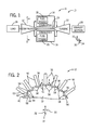
- FIG. 1 is a schematic block diagram of an embodiment of a turbomachine system 10 having a blade locking assembly to secure rotary blades.
- the system 10 includes a gas turbine engine 11 having a compressor 12, combustors 14 and 16 with respective fuel nozzles 18 and 20, a turbine 22, a shaft 24, a driven load 26, and an exhaust section 28.
- a gas turbine engine 11 having a compressor 12, combustors 14 and 16 with respective fuel nozzles 18 and 20, a turbine 22, a shaft 24, a driven load 26, and an exhaust section 28.
- FIGS. 1-13 reference may be made to a circumferential direction or axis 30, a radial direction or axis 32, and an axial direction or axis 34.
- the axial direction or axis 34 corresponds to a rotational axis of the system 10, while the circumferential direction 30 extends around the axis 34, and the radial direction 32 extends away from the axis 34.
- the compressor 12 and the turbine 22 each include one or more stages, wherein each stage includes a plurality of rotary blades that may be secured to a respective rotor by a blade locking assembly as discussed in detail below.
- the compressor 12 receives and compresses an air flow through one or more stages of rotary compressor blades.
- the fuel nozzles 18 and 20 mix fuel with the compressed air flow to generate an air-fuel mixture in the combustors 14 and 16, which then combust the mixture to generate hot combustion gases.
- the compressed airflow also may provide cooling for the combustors 14 and 16 and other components of the gas turbine engine 11.
- the hot combustion gases then flow through the turbine 22, thereby driving one or more stages of rotary turbine blades.
- the rotation of the turbine 22 causes rotation of the shaft 24, which in turn drives the compressor 12 and the load 26 (e.g., an electrical generator). Finally, the combustion gases pass through the exhaust section 28.
- the compressor 12 and/or the turbine 22 may include a blade locking assembly configured to secure blades to a respective rotor without deforming the rotor (e.g., without staking or welding).
- a blade locking assembly configured to secure blades to a respective rotor without deforming the rotor (e.g., without staking or welding).
- at least one insert may be deformed to serve as a blockage or lock, thereby holding the blade in place relative to the rotor.
- removal and replacement of the blade may be achieved by severing the deformed insert, discarding the insert, and using a new insert that can be deformed in a similar manner to secure the new blade.
- the deformation is performed on a removable, disposable insert, rather on the more expensive, robust rotor.
- the inserts may be used to secure a blade on a rotor of any turbomachine, the inserts of the disclosed blade locking assembly may be particularly well suited for mounting rotary blades on a compressor.
- FIG. 2 is a partial cross-sectional view of an embodiment of the compressor 12 of FIG. 1 , taken along line 2-2, illustrating an embodiment of a blade mounting system 40 having a sliding joint system 42 and a blade locking system 44.
- the compressor 12 includes a plurality of compressor blades 50 coupled to a rotor 52 about a circumference of the rotor 52.
- Each blade 50 includes a base mounting portion 54 (e.g., a sliding joint portion) that mates with the rotor 52 along a corresponding mounting portion 56 (e.g., a sliding joint portion).
- the base mounting portion 54 is a male sliding joint portion
- the mounting portion 56 is a female sliding joint portion.
- the base mounting portion 54 is a female sliding joint portion, while the mounting portion 56 is a male sliding joint portion.
- the mounting or sliding joint portions 54 and 56 may engage and disengage from one another in the axial direction 34 along the rotational axis of the system 10.
- the sliding joint portions 54 and 56 are configured to hold the blade 50 to the rotor 52 in the circumferential direction 30 and the radial direction 32, while allowing movement in the axial direction 34.
- the blade locking system 44 is configured to block movement of the blade 50 in the axial direction 34, thereby locking the blade 50 in place relative to the rotor 52.
- the blade locking system 44 includes a blade locking assembly 58 configured to interface with the sliding joint portions 54 and 56, and lock the joint portions 54 and 56 together without deforming the rotor 52.
- the sliding joint portions 54 and 56 may have any suitable shape or configuration
- the following discussion of the blade locking assembly 44 refers to the sliding joint portion 54 as an axial rail 54 (e.g., a dovetail shaped axial rail), and refers to the sliding joint portion 56 as an axial groove 56 (e.g., a dovetail shaped axial groove).
- the locking assembly 58 itself is subjected to deformation, such as staking, to hold the locking assembly 58 in the axial groove 56 to block removal of the axial rail 56.
- the locking assembly 58 may include a plurality of inserts, which are sequentially inserted and then staked together along the axial groove 56. Once staked together, the inserts are held in place along the axial groove 56 to block movement of the axial rail 56.
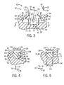
- FIG. 3 is a partial cross-sectional view of an embodiment of the blade mounting system 40 of FIG. 2 , taken within line 3-3, further illustrating details of the sliding joint system 42 and the blade locking system 44.
- the illustrated sliding joint system 42 includes the axial rail 54 of the blade 50 disposed in the axial groove 56 of the rotor 52.
- the configuration may be reversed such that the blade 50 includes the axial groove 56 and the rotor 52 includes the axial rail 54.
- the axial rail 54 may include a neck portion 60 and an enlarged head portion 62, which generally diverges away from the neck portion 60 to form a substantially triangular shaped head portion 62.
- the axial rail 54 may have a T-shaped structure, an L-shaped structure, or the like.
- the axial groove 56 may include an opening 64 along an exterior 66 of the rotor 52, wherein the opening 64 leads into an enlarged cavity 68.
- the enlarged cavity 68 similar to the enlarged head portion 62, generally diverges away from the opening 64 to form a substantially triangular shaped cavity 68.
- the illustrated geometry of the axial rail 54 and axial groove 56 is not intended to be limited, and may be replaced with a variety of other axial joint 54 and 56.
- the blade locking system 44 includes the locking assembly 58 disposed in opposite recesses 71 and 73 in the blade 50 and the rotor 52, respectively.
- the recess 71 is disposed in the axial rail 54 of the blade 50
- the recess 73 is disposed in the axial groove 56 of the rotor 52.
- the recess 71 has a height 70 in the radial direction 32
- the recess 73 has a height 72 in the radial direction 32.
- the height 70 of the recess 71 may be approximately 1 to 50, 2 to 25, or 5 to 10 mm
- the height 72 of the recess 73 may be approximately 1 to 50, 2 to 25, or 5 to 10 mm
- the heights 70 and 72 may be the same or different from one another.
- the height 70 may be approximately 5 to 500, 10 to 250, 20 to 100, or 30 to 50 percent greater than the height 72, or vice versa.
- the different heights 70 and 72 may facilitate operation of the locking assembly 58, as discussed in further detail below.
- the locking assembly 58 includes a first locking insert 74 with a height 76 in the radial direction 32, and a second locking insert 78 with a height 80 in the radial direction 32.
- the first and second locking inserts 74 and 78 are coupled together via a deformation (e.g., staking) 82 of at least one of the inserts 74 or 78.
- the staking 82 is disposed on the first locking insert 74 to secure the second locking insert 78.
- the first locking insert 74 is inserted into the recess 71 in the radial direction 32.
- the blade is coupled to the rotor 52 by axially sliding the axial rail 54 into the axial groove 56 until the recesses 71 and 73 are aligned with one another (i.e., same axial position).
- This is followed by lowering the first locking insert 74 from the recess 71 into the recess 73 in the rotor 52 in the radial direction 32.
- the first locking insert 74 is unable to move in the axial direction 34 and the circumferential direction 30, although the insert 74 can still move in the radial direction 32.
- the height 76 of the first locking insert 74 is greater than the height 72 of the recess 73, such that the first locking insert 74 overlaps both recesses 71 and 73 in the radial direction 32.
- the first locking insert 74 blocks axial movement 34 of the axial rail 54 relative to the axial groove 56 while overlapping the first and second recesses 71 and 73. Nevertheless, the first locking insert 74 is not yet secured in the recesses 71 and 73, as it can still move in the radial direction 32.
- the second locking insert 78 may be inserted into the recess 71 in the axial rail 54 in the axial direction 34, thereby blocking radial movement 32 of the first locking insert 74.
- the sum of the heights 72 and 74 of the recesses 71 and 73 is substantially equal to the sum of the heights 76 and 80 of the first and second locking inserts 74 and 78.
- the inserts 74 and 78 are substantially blocked from moving in the radial direction 32 within the recesses 71 and 73.
- the inserts 74 and 78 are also secured to one another to block axial movement 34.
- the second locking insert 78 may be secured to the first locking insert 74 by deformation of one insert relative to the other.
- the illustrated embodiment depicts the deformation (e.g., staking) 82 disposed on the first locking insert 74, causing a portion 84 of the first locking insert 74 to deform in the radial direction 32 overlapping the second locking insert 78.
- the overlapping portion 84 associated with the deformation (e.g., staking) 82 blocks axial movement 34 of the second locking insert 78, such that the insert 78 remains in place to secure the first locking insert 74.
- the first and second locking inserts 74 and 78 may be coupled together by other mechanisms, such as a welded joint.
- the first and second locking inserts 74 and 78 may be made of a heat resistant material, a corrosion resistant material, a wear resistant material, or a combination thereof.
- the inserts 74 and 78 may be made of various alloys, such as nickel-based steel alloys.
- the inserts 74 and 78 may be used at one or both ends of the sliding joint system 42 for each blade 50.
- the recesses 71 and 73 and the inserts 74 and 78 may have a variety of shapes configured to lock the sliding joint system 42.
- FIG. 4 is a partial cross-sectional view of an embodiment of the blade mounting system 40 of FIG. 3 , taken along line 4-4, further illustrating details of the blade locking system 44 in the sliding joint system 42 (e.g., between the rail 54 and groove 56).
- the first locking insert 74 is depicted within the recess 73 of the rotor 52 after radially 32 lowering the insert 74 from the recess 71 to the recess 73 as discussed above.
- the illustrated recess 73 and first locking insert 74 are shaped to block movement of the insert 74 in the axial direction 34.
- the recess 73 and the insert 74 have a nonuniform width (e.g., variable width) in the axial direction 34, such that the insert 74 cannot be removed from the recess 73 in the axial direction 34.
- the recess 73 and the first locking insert 74 have a first diameter 100 and a second diameter 102 at an axial offset 104 from one another in the axial direction 34, wherein the first diameter 100 is greater than the second diameter 102.
- the first diameter 100 may be approximately 5 to 200, 10 to 100, or 20 to 50 percent greater than the second diameter 102.
- the first and second diameters 100 and 102 may be disposed at a variety of axial locations 34 along the recess 73 and the first locking insert 74.
- the first diameter 100 may be disposed at a generally central or intermediate portion 90 of the recess 73 and the first locking insert 74, while the second diameter 100 may be disposed along an edge portion 92 of the recess 73 and the first locking insert 74.
- the second diameter 102 is disposed along an axial edge 94 of the rotor 52, such that the edge portion 92 of the recess 73 and the first locking insert 74 is disposed along the axial edge 94.
- the recess 73 includes an opening 96 disposed along the axial edge 94 of the rotor 52, and an enlarged cavity 98 disposed within the rotor 52 in an axial inward direction 34 away from the axial edge 94.
- the enlarged cavity 98 has the second diameter 102, while the opening 96 has the first diameter 100.
- the first locking insert 74 includes a neck portion 106 disposed along the axial edge 94 of the rotor 52, and an enlarged body portion 108 disposed within the rotor 52 in an axial inward direction 34 away from the axial edge 94.
- the enlarged body portion 108 has the second diameter 102, while the neck portion 106 has the first diameter 100.
- the recess 73 is a truncated cylindrical recess
- the first locking insert 74 is a truncated cylindrical insert.
- any other shapes may be employed for the recess 73 and insert 74, provided the shapes block axial withdrawal 34 of the insert 74 from the recess 73.
- FIG. 5 is a partial cross-sectional view of an embodiment of the blade mounting system 40 of FIG. 3 , taken along line 5-5, further illustrating details of the blade locking system 44 in the sliding joint system 42 (e.g., between the rail 54 and groove 56).
- the second locking insert 78 is depicted within the recess 71 of the axial rail 54. As illustrated, the second locking insert 78 has a generally rectangular shape, which has a width 110 in the circumferential dimension 30.
- the recess 71 has an opening 112 and an enlarged cavity 114, wherein the opening 112 is disposed along an axial edge 116 of the rail 54 and the cavity 114 is disposed axially inward 34 away from the axial edge 116.
- the illustrated recess 71 is a truncated cylindrical recess with first and second diameters 118 and 120, wherein the second diameter 120 is greater than the first diameter 118.
- the opening 112 of the recess 71 has the first diameter 118, while the enlarged cavity 114 has the second diameter 120.
- the width 110 of the second locking insert 78 is less than the first diameter 118 of the recess 71, thereby enabling insertion and removal of the second locking insert 78 in the axial direction 34.
- the first diameter 118 may be approximately 0 to 20 or 5 to 10 percent larger than the width 110.
- the first locking insert 74 may be deformed (e.g., staked) 82 to extend the portion 84 radially 32 overlapping the second locking insert 78.
- the second locking insert 78 may be axially 34 retained within the recess 71, thereby securing the first locking insert 74.
- the first and second locking inserts 74 and 78 are secured together to block axial movement 34 of the axial rail 54 relative to the axial groove 56.
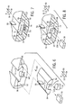
- FIGS. 6 through 9 are partial perspective views of an embodiment of the blade mounting system 40 of FIG. 3 , further illustrating steps of mounting the blade 50 to the rotor 52 using the sliding joint system 42 and the blade locking system 44.
- FIG. 6 is a partial exploded perspective view illustrating an embodiment of the blade 50 having the axial rail 54, the first locking insert 74, and second locking insert 78 exploded from the axial groove 56 in the rotor 52.
- the first locking insert 74 and the recess 71 (similar to the recess 73) have a truncated cylindrical shape, such that the locking insert 74 cannot be inserted or removed in the axial direction 34 relative to the recess 71.
- the first locking insert 74 is inserted into the recess 71 in the radial direction 32, as indicated by arrow 130.
- the axial rail 54 of the blade 50 may be installed in the axial direction 34 into the axial groove 56, as indicated by arrow 132.
- the axial rail 54 is moved axially 34 along the axial groove 56 until the recess 71 of the blade 50 is axially aligned with the recess 73 of the rotor 52, as illustrated in FIG. 7 .
- the first locking insert 74 is lowered from the recess 71 into the recess 73 as indicated by arrow 134.
- the insert 74 may automatically drop into the recess 73 upon axial alignment of the recesses 71 and 73.
- the first locking insert 74 radially overlaps 32 both recesses 71 and 73 in the lowered position of the insert 74, thereby blocking axial movement 34 of the axial rail 54 relative to the axial groove 56.
- the first locking insert 74 is still capable of moving in the radial direction 32, and thus the axial rail 54 is not completely secured to the axial groove 56 at this stage.
- the second locking insert 78 is inserted axially 34 into the recess 71 on top of the first locking insert 74, as indicated by arrow 136.
- FIG. 9 illustrates a deformation (e.g., staking) 82 in the first locking insert 74, which causes the portion 84 of the insert 74 to radially 32 overlap the second locking insert 78.
- the first locking insert 74 blocks axial movement 34 of the axial rail 54 relative to the axial groove 56
- the second locking insert 78 blocks radial movement 32 of the first locking insert 74
- the deformation (e.g., staking) 82 blocks axial movement 34 of the second locking insert 78 relative to the axial rail 54.
- the inserts 74 and 78 completely secure the axial rail 54 to the axial groove 56 without directly staking the rotor 52 or the blade 50.
- FIGS. 10 through 13 are partial cross-sectional views of embodiments of the blade locking system 44 of FIG. 3 , taken along line 4-4; illustrating different locking interfaces between the recess 73 and the first locking insert 74.
- recess 71 of FIG. 3 may have any of the geometric shapes depicted in FIGS. 10 through 13 .
- FIG. 10 illustrates a T-shaped locking interface 140, wherein the recess 73 and the first locking insert 74 both have a T-shaped geometry.
- FIG. 11 illustrates a wedge-shaped locking interface 150, wherein the recess 73 and the first locking insert 74 both have a wedge-shaped geometry.
- FIG. 10 illustrates a T-shaped locking interface 140, wherein the recess 73 and the first locking insert 74 both have a T-shaped geometry.
- FIG. 11 illustrates a wedge-shaped locking interface 150, wherein the recess 73 and the first locking insert 74 both have a wedge-shaped geometry.
- FIG. 10 illustrates a
- FIG. 12 illustrates a bulb-shaped locking interface 160, wherein the recess 73 and the first locking insert 74 both have a bulb-shaped geometry.
- FIG. 13 illustrates an L-shaped locking interface 170, wherein the recess 73 and the first locking insert 74 both have an L-shaped geometry.
- the locking interfaces 140, 150, 160, and 170 block axial movement 34 of the insert 74 relative to the recess 73, while allowing radial movement 32 of the insert 74 relative to the recess 73.
- the second locking insert 78 is subsequently installed to block the radial movement 32 of the first locking insert 74.
- a variety of other shapes may be used for the insert 74 and recess 73 (and recess 71 depicted in FIG. 3 ), provided that the shapes block axial movement 34.
- the disclosed blade locking system 44 enables blades 50 to be installed and secured on a turbomachine 10, such as a compressor.
- a turbomachine 10 such as a compressor.
- the improved design incorporated into the blade locking system enables the turbomachine rotor 52 to retain its supporting shape and not be deformed, even with multiple blade 50 replacements.
- the locking assembly 58 may be deformed.
- the locking assembly 58 may be generally easier to install and cost less than a turbomachine rotor 52.
- the improved design enables the turbomachine rotor 52 to have an increased usable life and reduced costs associated therewith.
- the improved design enables turbomachine blades 50 to be replaced when needed.
Landscapes
- Engineering & Computer Science (AREA)
- Mechanical Engineering (AREA)
- General Engineering & Computer Science (AREA)
- Turbine Rotor Nozzle Sealing (AREA)
- Structures Of Non-Positive Displacement Pumps (AREA)
Abstract
Description
- The disclosed subject matter relates to turbomachines and, more particularly, a locking system for blades.
- In general, turbomachines transfer energy between a fluid and rotating blades. For example, a compressor is driven to rotate blades to compress a gas, such as air. By further example, a turbine includes blades, which are driven to rotate by a fluid flow, such as water, steam, or combustion gases. A typical turbomachine includes a large number of blades coupled to a rotor. Unfortunately, the rotor may be deformed during the attachment of the blades. For example, the blades may be staked or welded directly to the rotor, which deforms the rotor in the vicinity of the blades. At some point during the life of the turbomachine, the blades may be removed and replaced with new blades. As a result, the rotor may be repeatedly deformed during each successive blade replacement, eventually leading to problems attaching a new blade to the rotor. Therefore, a need exists to secure turbomachine blades to the rotor without repeatedly deforming the rotor.
- Certain embodiments commensurate in scope with the originally claimed invention are summarized below. These embodiments are not intended to limit the scope of the claimed invention, but rather these embodiments are intended only to provide a brief summary of possible forms of the invention. Indeed, the invention may encompass a variety of forms that may be similar to or different from the embodiments set forth below.
- The present invention resides in a system including a turbomachine blade that has a blade portion extending from a base portion. The base portion includes an axial rail configured to extend into an axial groove disposed in a rotor of a turbomachine. The axial rail includes a first locking recess configured to align with a second locking recess along the axial groove. The system also includes a blade locking assembly having a first locking insert and a second locking insert. The first locking insert is configured to be inserted in both the first and second locking recesses. The second locking insert is configured to be inserted in the first or second locking recess adjacent the first locking insert.
- The invention further resides in a system including a turbomachine having a rotor with a first axial groove. The turbomachine also includes a first blade having a first axial rail disposed in the first axial groove and a locking space extending into the first axial groove and the first axial rail. The turbomachine includes at least one locking insert disposed in the locking space. At least one locking insert blocks movement of the first axial rail relative to the first axial groove in an axial direction.
- The invention also resides in a system including a compressor having a first blade with a first axial mount. The compressor also includes a rotor having a second axial mount. The first and second axial mounts couple together in an axial direction to block movement of the first axial mount relative to the second axial mount in a radial direction and a circumferential direction. The compressor includes a locking space extending into the first axial mount and the second axial mount. The compressor also includes at least one locking insert disposed in the locking space. The at least one locking insert blocks movement of the first axial mount relative to the second axial mount in the axial direction.
- Embodiments of the present invention will now be described, by way of example only, with reference to the accompanying drawings in which:
-
FIG. 1 is a schematic block diagram of an embodiment of a turbomachine system, illustrating a gas turbine engine having a compressor and a turbine; -
FIG. 2 is a partial cross-sectional view of an embodiment of the compressor ofFIG. 1 , taken along line 2-2, illustrating an embodiment of a blade locking system; -
FIG. 3 is a partial cross-sectional view of an embodiment of the blade locking system ofFIG. 2 , taken within line 3-3; -
FIG. 4 is a partial cross-sectional view of an embodiment of the blade locking system ofFIG. 3 , taken along line 4-4; -
FIG. 5 is a partial cross-sectional view of an embodiment of the blade locking system ofFIG. 3 , taken along line 5-5; -
FIG. 6 is a partial exploded perspective view of an embodiment of the blade locking system ofFIG. 2 , illustrating a blade, first locking insert, and second locking insert exploded from a groove in a rotor; -
FIG. 7 is a partial cutaway perspective view of an embodiment of the blade locking system ofFIG. 6 , illustrating the blade and the first locking insert disposed in the groove in the rotor, with the first locking insert in a first position; -
FIG. 8 is a partial cutaway perspective view of an embodiment of the blade locking system ofFIGS. 6-7 , illustrating the blade and the first locking insert disposed in the groove in the rotor, with the first locking insert in a second position; -
FIG. 9 is a partial cutaway perspective view of an embodiment of the blade locking system ofFIGS. 6-8 , illustrating the blade, the first locking insert, and the second locking insert disposed in the groove in the rotor, with the first locking insert in a second position secured by the second locking insert; -
FIG. 10 is a partial cross-sectional view of an embodiment of the blade locking system ofFIG. 3 , taken along line 4-4; illustrating a T-shaped locking interface of the blade locking system ofFIG. 2 ; -
FIG. 11 is a partial cross-sectional view of an embodiment of the blade locking system ofFIG. 3 , taken along line 4-4; illustrating a wedge-shaped locking interface of the blade locking system ofFIG. 2 ; -
FIG. 12 is a partial cross-sectional view of an embodiment of the blade locking system ofFIG. 3 , taken along line 4-4; illustrating a bulb-shaped locking interface of the blade locking system ofFIG. 2 ; and -
FIG. 13 is a partial cross-sectional view of an embodiment of the blade locking system ofFIG. 3 , taken along line 4-4; illustrating an L-shaped locking interface of the blade locking system ofFIG. 2 . - One or more specific embodiments of the present invention will be described below. In an effort to provide a concise description of these embodiments, all features of an actual implementation may not be described in the specification. It should be appreciated that in the development of any such actual implementation, as in any engineering or design project, numerous implementation-specific decisions must be made to achieve the developers' specific goals, such as compliance with system-related and business-related constraints, which may vary from one implementation to another. Moreover, it should be appreciated that such a development effort might be complex and time consuming, but would nevertheless be a routine undertaking of design, fabrication, and manufacture for those of ordinary skill having the benefit of this disclosure.
- When introducing elements of various embodiments of the present invention, the articles "a," "an," "the," and "said" are intended to mean that there are one or more of the elements. The terms "comprising," "including," and "having" are intended to be inclusive and mean that there may be additional elements other than the listed elements.
- As discussed in detail below, the disclosed embodiments include a blade locking assembly configured to lock a blade to a rotor of a turbomachine without directly staking or otherwise deforming the rotor. The turbomachine may include a turbine, a compressor, or a combination thereof. For example, the blade locking assembly may be used to secure compressor blades in one or more stages of a compressor in a gas turbine engine. In certain embodiments, each blade is coupled to the rotor along a sliding joint, such as an axial rail and an axial groove. For example, the sliding joint may include a dovetail joint with a male portion and a female portion, which slide together in an axial direction relative to a rotational axis of the rotor. Furthermore, the blade locking assembly may include a plurality of inserts, which interface with one another between each blade and the rotor (e.g., along the sliding joint), thereby blocking axial movement of the blade relative to the rotor. In particular, rather than staking, welding, or otherwise deforming the rotor, the disclosed embodiments of the blade locking assembly may deform at least one of the inserts to hold the blade to the rotor along the sliding joint. For example, first and second inserts may be deformed relative to one another (e.g., by staking one of the inserts) to lock the inserts together, thereby blocking axial movement of the blade relative to the sliding joint. Although the disclosed embodiments are discussed in context of a compressor, any application involving attachment of a blade to a rotor may employ the blade locking assembly discussed in detail below.
- Turning to the figures,
FIG. 1 is a schematic block diagram of an embodiment of aturbomachine system 10 having a blade locking assembly to secure rotary blades. As illustrated, thesystem 10 includes agas turbine engine 11 having acompressor 12,combustors respective fuel nozzles turbine 22, ashaft 24, a drivenload 26, and anexhaust section 28. In the following discussion ofFIGS. 1-13 , reference may be made to a circumferential direction oraxis 30, a radial direction oraxis 32, and an axial direction oraxis 34. The axial direction oraxis 34 corresponds to a rotational axis of thesystem 10, while thecircumferential direction 30 extends around theaxis 34, and theradial direction 32 extends away from theaxis 34. In the illustrated embodiment, thecompressor 12 and theturbine 22 each include one or more stages, wherein each stage includes a plurality of rotary blades that may be secured to a respective rotor by a blade locking assembly as discussed in detail below. - In operation, the
compressor 12 receives and compresses an air flow through one or more stages of rotary compressor blades. The fuel nozzles 18 and 20 mix fuel with the compressed air flow to generate an air-fuel mixture in thecombustors combustors gas turbine engine 11. The hot combustion gases then flow through theturbine 22, thereby driving one or more stages of rotary turbine blades. The rotation of theturbine 22 causes rotation of theshaft 24, which in turn drives thecompressor 12 and the load 26 (e.g., an electrical generator). Finally, the combustion gases pass through theexhaust section 28. - As noted above, the
compressor 12 and/or theturbine 22 may include a blade locking assembly configured to secure blades to a respective rotor without deforming the rotor (e.g., without staking or welding). For example, rather than staking the rotor, at least one insert may be deformed to serve as a blockage or lock, thereby holding the blade in place relative to the rotor. Subsequently, removal and replacement of the blade may be achieved by severing the deformed insert, discarding the insert, and using a new insert that can be deformed in a similar manner to secure the new blade. In other words, the deformation is performed on a removable, disposable insert, rather on the more expensive, robust rotor. Although the inserts may be used to secure a blade on a rotor of any turbomachine, the inserts of the disclosed blade locking assembly may be particularly well suited for mounting rotary blades on a compressor. -
FIG. 2 is a partial cross-sectional view of an embodiment of thecompressor 12 ofFIG. 1 , taken along line 2-2, illustrating an embodiment of ablade mounting system 40 having a slidingjoint system 42 and ablade locking system 44. In the illustrated embodiment, thecompressor 12 includes a plurality ofcompressor blades 50 coupled to arotor 52 about a circumference of therotor 52. Eachblade 50 includes a base mounting portion 54 (e.g., a sliding joint portion) that mates with therotor 52 along a corresponding mounting portion 56 (e.g., a sliding joint portion). For example, in the illustrated embodiment, thebase mounting portion 54 is a male sliding joint portion, while the mountingportion 56 is a female sliding joint portion. In other embodiments, thebase mounting portion 54 is a female sliding joint portion, while the mountingportion 56 is a male sliding joint portion. In either configuration, the mounting or slidingjoint portions axial direction 34 along the rotational axis of thesystem 10. The slidingjoint portions blade 50 to therotor 52 in thecircumferential direction 30 and theradial direction 32, while allowing movement in theaxial direction 34. Accordingly, theblade locking system 44 is configured to block movement of theblade 50 in theaxial direction 34, thereby locking theblade 50 in place relative to therotor 52. In particular, as discussed in detail below, theblade locking system 44 includes ablade locking assembly 58 configured to interface with the slidingjoint portions joint portions rotor 52. - Although the sliding
joint portions blade locking assembly 44 refers to the slidingjoint portion 54 as an axial rail 54 (e.g., a dovetail shaped axial rail), and refers to the slidingjoint portion 56 as an axial groove 56 (e.g., a dovetail shaped axial groove). In certain embodiments, the lockingassembly 58 itself is subjected to deformation, such as staking, to hold the lockingassembly 58 in theaxial groove 56 to block removal of theaxial rail 56. For example, the lockingassembly 58 may include a plurality of inserts, which are sequentially inserted and then staked together along theaxial groove 56. Once staked together, the inserts are held in place along theaxial groove 56 to block movement of theaxial rail 56. -
FIG. 3 is a partial cross-sectional view of an embodiment of theblade mounting system 40 ofFIG. 2 , taken within line 3-3, further illustrating details of the slidingjoint system 42 and theblade locking system 44. The illustrated slidingjoint system 42 includes theaxial rail 54 of theblade 50 disposed in theaxial groove 56 of therotor 52. However, the configuration may be reversed such that theblade 50 includes theaxial groove 56 and therotor 52 includes theaxial rail 54. In either configuration, theaxial rail 54 may include aneck portion 60 and anenlarged head portion 62, which generally diverges away from theneck portion 60 to form a substantially triangular shapedhead portion 62. In another embodiment, theaxial rail 54 may have a T-shaped structure, an L-shaped structure, or the like. Similarly, theaxial groove 56 may include anopening 64 along anexterior 66 of therotor 52, wherein theopening 64 leads into anenlarged cavity 68. Theenlarged cavity 68, similar to theenlarged head portion 62, generally diverges away from theopening 64 to form a substantially triangular shapedcavity 68. Again, the illustrated geometry of theaxial rail 54 andaxial groove 56 is not intended to be limited, and may be replaced with a variety of other axial joint 54 and 56. - The
blade locking system 44 includes the lockingassembly 58 disposed inopposite recesses blade 50 and therotor 52, respectively. In particular, therecess 71 is disposed in theaxial rail 54 of theblade 50, while therecess 73 is disposed in theaxial groove 56 of therotor 52. Therecess 71 has aheight 70 in theradial direction 32, while therecess 73 has aheight 72 in theradial direction 32. In certain embodiments, theheight 70 of therecess 71 may be approximately 1 to 50, 2 to 25, or 5 to 10 mm, and theheight 72 of therecess 73 may be approximately 1 to 50, 2 to 25, or 5 to 10 mm Furthermore, theheights height 70 may be approximately 5 to 500, 10 to 250, 20 to 100, or 30 to 50 percent greater than theheight 72, or vice versa. Thedifferent heights assembly 58, as discussed in further detail below. - The locking
assembly 58 includes afirst locking insert 74 with aheight 76 in theradial direction 32, and asecond locking insert 78 with aheight 80 in theradial direction 32. Within therecesses inserts first locking insert 74 to secure thesecond locking insert 78. Once locked in place in therecesses assembly 58 blockaxial movement 34 of theaxial rail 54 relative to theaxial groove 56. - During the assembly process, the
first locking insert 74 is inserted into therecess 71 in theradial direction 32. After insertion of theinsert 74 into therecess 71, the blade is coupled to therotor 52 by axially sliding theaxial rail 54 into theaxial groove 56 until therecesses first locking insert 74 from therecess 71 into therecess 73 in therotor 52 in theradial direction 32. Once inside therecess 73, thefirst locking insert 74 is unable to move in theaxial direction 34 and thecircumferential direction 30, although theinsert 74 can still move in theradial direction 32. Furthermore, theheight 76 of thefirst locking insert 74 is greater than theheight 72 of therecess 73, such that thefirst locking insert 74 overlaps bothrecesses radial direction 32. As a result, thefirst locking insert 74 blocksaxial movement 34 of theaxial rail 54 relative to theaxial groove 56 while overlapping the first andsecond recesses first locking insert 74 is not yet secured in therecesses radial direction 32. - Accordingly, the
second locking insert 78 may be inserted into therecess 71 in theaxial rail 54 in theaxial direction 34, thereby blockingradial movement 32 of thefirst locking insert 74. As illustrated, the sum of theheights recesses heights inserts radial direction 32 within therecesses inserts axial movement 34. For example, thesecond locking insert 78 may be secured to thefirst locking insert 74 by deformation of one insert relative to the other. Again, the illustrated embodiment depicts the deformation (e.g., staking) 82 disposed on thefirst locking insert 74, causing aportion 84 of thefirst locking insert 74 to deform in theradial direction 32 overlapping thesecond locking insert 78. Thus, the overlappingportion 84 associated with the deformation (e.g., staking) 82 blocksaxial movement 34 of thesecond locking insert 78, such that theinsert 78 remains in place to secure thefirst locking insert 74. Furthermore, the first and second locking inserts 74 and 78 may be coupled together by other mechanisms, such as a welded joint. - The first and second locking inserts 74 and 78 may be made of a heat resistant material, a corrosion resistant material, a wear resistant material, or a combination thereof. For example, the
inserts inserts joint system 42 for eachblade 50. As discussed below, therecesses inserts joint system 42. -
FIG. 4 is a partial cross-sectional view of an embodiment of theblade mounting system 40 ofFIG. 3 , taken along line 4-4, further illustrating details of theblade locking system 44 in the sliding joint system 42 (e.g., between therail 54 and groove 56). As illustrated, thefirst locking insert 74 is depicted within therecess 73 of therotor 52 after radially 32 lowering theinsert 74 from therecess 71 to therecess 73 as discussed above. The illustratedrecess 73 and first lockinginsert 74 are shaped to block movement of theinsert 74 in theaxial direction 34. In particular, therecess 73 and theinsert 74 have a nonuniform width (e.g., variable width) in theaxial direction 34, such that theinsert 74 cannot be removed from therecess 73 in theaxial direction 34. - The
recess 73 and thefirst locking insert 74 have afirst diameter 100 and asecond diameter 102 at an axial offset 104 from one another in theaxial direction 34, wherein thefirst diameter 100 is greater than thesecond diameter 102. For example, thefirst diameter 100 may be approximately 5 to 200, 10 to 100, or 20 to 50 percent greater than thesecond diameter 102. The first andsecond diameters axial locations 34 along therecess 73 and thefirst locking insert 74. For example, thefirst diameter 100 may be disposed at a generally central orintermediate portion 90 of therecess 73 and thefirst locking insert 74, while thesecond diameter 100 may be disposed along anedge portion 92 of therecess 73 and thefirst locking insert 74. As illustrated, thesecond diameter 102 is disposed along anaxial edge 94 of therotor 52, such that theedge portion 92 of therecess 73 and thefirst locking insert 74 is disposed along theaxial edge 94. - In other words, the
recess 73 includes anopening 96 disposed along theaxial edge 94 of therotor 52, and anenlarged cavity 98 disposed within therotor 52 in an axialinward direction 34 away from theaxial edge 94. Theenlarged cavity 98 has thesecond diameter 102, while theopening 96 has thefirst diameter 100. Similarly, thefirst locking insert 74 includes aneck portion 106 disposed along theaxial edge 94 of therotor 52, and anenlarged body portion 108 disposed within therotor 52 in an axialinward direction 34 away from theaxial edge 94. Theenlarged body portion 108 has thesecond diameter 102, while theneck portion 106 has thefirst diameter 100. In the illustrated embodiment, therecess 73 is a truncated cylindrical recess, and thefirst locking insert 74 is a truncated cylindrical insert. However, any other shapes may be employed for therecess 73 andinsert 74, provided the shapes blockaxial withdrawal 34 of theinsert 74 from therecess 73. -
FIG. 5 is a partial cross-sectional view of an embodiment of theblade mounting system 40 ofFIG. 3 , taken along line 5-5, further illustrating details of theblade locking system 44 in the sliding joint system 42 (e.g., between therail 54 and groove 56). Thesecond locking insert 78 is depicted within therecess 71 of theaxial rail 54. As illustrated, thesecond locking insert 78 has a generally rectangular shape, which has awidth 110 in thecircumferential dimension 30. Therecess 71 has anopening 112 and anenlarged cavity 114, wherein theopening 112 is disposed along anaxial edge 116 of therail 54 and thecavity 114 is disposed axially inward 34 away from theaxial edge 116. Similar to therecess 73, the illustratedrecess 71 is a truncated cylindrical recess with first andsecond diameters second diameter 120 is greater than thefirst diameter 118. In the illustrated embodiment, theopening 112 of therecess 71 has thefirst diameter 118, while theenlarged cavity 114 has thesecond diameter 120. Thewidth 110 of thesecond locking insert 78 is less than thefirst diameter 118 of therecess 71, thereby enabling insertion and removal of thesecond locking insert 78 in theaxial direction 34. For example, thefirst diameter 118 may be approximately 0 to 20 or 5 to 10 percent larger than thewidth 110. After insertion of theinsert 78 into therecess 71, thefirst locking insert 74 may be deformed (e.g., staked) 82 to extend theportion 84 radially 32 overlapping thesecond locking insert 78. As a result of the overlappingportion 84, thesecond locking insert 78 may be axially 34 retained within therecess 71, thereby securing thefirst locking insert 74. Thus, the first and second locking inserts 74 and 78 are secured together to blockaxial movement 34 of theaxial rail 54 relative to theaxial groove 56. -
FIGS. 6 through 9 are partial perspective views of an embodiment of theblade mounting system 40 ofFIG. 3 , further illustrating steps of mounting theblade 50 to therotor 52 using the slidingjoint system 42 and theblade locking system 44.FIG. 6 is a partial exploded perspective view illustrating an embodiment of theblade 50 having theaxial rail 54, thefirst locking insert 74, and second lockinginsert 78 exploded from theaxial groove 56 in therotor 52. As discussed above, thefirst locking insert 74 and the recess 71 (similar to the recess 73) have a truncated cylindrical shape, such that the lockinginsert 74 cannot be inserted or removed in theaxial direction 34 relative to therecess 71. - Accordingly, the
first locking insert 74 is inserted into therecess 71 in theradial direction 32, as indicated byarrow 130. After insertion of theinsert 74 into therecess 71, theaxial rail 54 of theblade 50 may be installed in theaxial direction 34 into theaxial groove 56, as indicated by arrow 132. Theaxial rail 54 is moved axially 34 along theaxial groove 56 until therecess 71 of theblade 50 is axially aligned with therecess 73 of therotor 52, as illustrated inFIG. 7 . At this stage, as further illustrated inFIG. 7 , thefirst locking insert 74 is lowered from therecess 71 into therecess 73 as indicated byarrow 134. For example, theinsert 74 may automatically drop into therecess 73 upon axial alignment of therecesses FIG. 8 , thefirst locking insert 74 radially overlaps 32 bothrecesses insert 74, thereby blockingaxial movement 34 of theaxial rail 54 relative to theaxial groove 56. However, thefirst locking insert 74 is still capable of moving in theradial direction 32, and thus theaxial rail 54 is not completely secured to theaxial groove 56 at this stage. As further illustrated inFIG. 8 , thesecond locking insert 78 is inserted axially 34 into therecess 71 on top of thefirst locking insert 74, as indicated byarrow 136. Once theinsert 78 is disposed above theinsert 74, theinserts axial rail 54 within theaxial groove 56.FIG. 9 illustrates a deformation (e.g., staking) 82 in thefirst locking insert 74, which causes theportion 84 of theinsert 74 to radially 32 overlap thesecond locking insert 78. At this stage, thefirst locking insert 74 blocksaxial movement 34 of theaxial rail 54 relative to theaxial groove 56, thesecond locking insert 78 blocksradial movement 32 of thefirst locking insert 74, and the deformation (e.g., staking) 82 blocksaxial movement 34 of thesecond locking insert 78 relative to theaxial rail 54. In this manner, theinserts axial rail 54 to theaxial groove 56 without directly staking therotor 52 or theblade 50. -
FIGS. 10 through 13 are partial cross-sectional views of embodiments of theblade locking system 44 ofFIG. 3 , taken along line 4-4; illustrating different locking interfaces between therecess 73 and thefirst locking insert 74. Furthermore, although not depicted in these figures,recess 71 ofFIG. 3 may have any of the geometric shapes depicted inFIGS. 10 through 13 . For example,FIG. 10 illustrates a T-shapedlocking interface 140, wherein therecess 73 and thefirst locking insert 74 both have a T-shaped geometry.FIG. 11 illustrates a wedge-shapedlocking interface 150, wherein therecess 73 and thefirst locking insert 74 both have a wedge-shaped geometry.FIG. 12 illustrates a bulb-shapedlocking interface 160, wherein therecess 73 and thefirst locking insert 74 both have a bulb-shaped geometry.FIG. 13 illustrates an L-shapedlocking interface 170, wherein therecess 73 and thefirst locking insert 74 both have an L-shaped geometry. In each of the embodiments ofFIGS. 10 through 13 , the lockinginterfaces axial movement 34 of theinsert 74 relative to therecess 73, while allowingradial movement 32 of theinsert 74 relative to therecess 73. Thus, thesecond locking insert 78 is subsequently installed to block theradial movement 32 of thefirst locking insert 74. In other embodiments, a variety of other shapes may be used for theinsert 74 and recess 73 (andrecess 71 depicted inFIG. 3 ), provided that the shapes blockaxial movement 34. - Technical effects of the disclosed embodiments include providing systems for improving the longevity of a
turbomachine rotor 52. The disclosedblade locking system 44 enablesblades 50 to be installed and secured on aturbomachine 10, such as a compressor. When theblades 50 are secured, the improved design incorporated into the blade locking system enables theturbomachine rotor 52 to retain its supporting shape and not be deformed, even withmultiple blade 50 replacements. Instead of deforming therotor 52, the lockingassembly 58 may be deformed. The lockingassembly 58 may be generally easier to install and cost less than aturbomachine rotor 52. Thus, the improved design enables theturbomachine rotor 52 to have an increased usable life and reduced costs associated therewith. Likewise, the improved design enablesturbomachine blades 50 to be replaced when needed. - This written description uses examples to disclose the invention, including the best mode, and also to enable any person skilled in the art to practice the invention, including making and using any devices or systems and performing any incorporated methods. The patentable scope of the invention is defined by the claims, and may include other examples that occur to those skilled in the art. Such other examples are intended to be within the scope of the claims if they have structural elements that do not differ from the literal language of the claims, or if they include equivalent structural elements with insubstantial differences from the literal languages of the claims.
- Various aspects and embodiments of the present invention are defined by the following numbered clauses:
- 1. A system, comprising:
- a turbomachine, comprising:
- a rotor having a first axial groove;
- a first blade having a first axial rail disposed in the first axial groove;
- a locking space extending into the first axial groove and the first axial rail; and
- at least one locking insert disposed in the locking space, wherein the at least one locking insert blocks movement of the first axial rail relative to the first axial groove in an axial direction.
- a turbomachine, comprising:
- 2. The system of clause 1, wherein the at least one locking insert comprises a first locking insert and a second locking insert.
- 3. The system of
clause 2, wherein the first and second locking inserts are staked relative to one another. - 4. The system of
clause 2, wherein the second locking insert retains the first locking insert within the locking space, and the first locking insert blocks movement of the first axial rail relative to the first axial groove in the axial direction while retained in the locking space. - 5. The system of clause 1, wherein the locking space comprises a first locking recess extending radially into the first axial rail and a second locking recess extending radially into the first axial groove, and the first and second locking recesses have different radial depths than one another.
- 6. The system of
clause 5, comprising a lateral opening extending into the locking space in the axial direction, wherein the locking space is sized greater than the lateral opening in a direction crosswise to the axial direction. - 7. A system, comprising:
- a compressor, comprising:
- a first blade having a first axial mount;
- a rotor having a second axial mount, wherein the first and second axial mounts couple together in an axial direction to block movement of the first axial mount relative to the second axial mount in a radial direction and a circumferential direction;
- a locking space extending into the first axial mount and the second axial mount; and
- at least one locking insert disposed in the locking space, wherein the at least one locking insert blocks movement of the first axial mount relative to the second axial mount in the axial direction.
- a compressor, comprising:
- 8. The system of clause 7, wherein the at least one locking insert comprises a first locking insert and a second locking insert, and the first and second locking inserts are staked relative to one another.
- 9. The system of clause 7, comprising a lateral opening extending into the locking space in the axial direction, wherein the locking space comprises a first locking recess extending radially into the first axial mount and a second locking recess extending radially into the second axial mount.
Claims (11)
- A system, comprising:a turbomachine blade (50) comprising a blade portion (60) extending from a base portion (54), wherein the base portion (54) comprises an axial rail (62) configured to extend into an axial groove (64) disposed in a rotor (52) of a turbomachine (10), and the axial rail (62) comprising a first locking recess (71) configured to align with a second locking recess (73) along the axial groove (64); anda blade locking assembly (58) comprising a first locking insert (74) and a second locking insert (78), wherein the first locking insert (74) is configured to be inserted in both the first (71) and second (73) locking recesses, and the second locking insert (78) is configured to be inserted in the first (71) or second (73) locking recess adjacent the first locking insert (74).
- The system of claim 1, wherein the first (74) and second (78) locking inserts are staked (82) relative to one another.
- The system of claim 1 or 2, wherein the axial rail (62) is configured to extend into the axial groove (64) to block movement of the turbomachine blade (50) relative to the rotor (52) in a radial direction (32) and a circumferential direction (30) relative to a rotational axis of the rotor (52).
- The system of claim 3, wherein the blade locking assembly (58) is configured to block movement of the turbomachine blade (50) relative to the rotor (52) in an axial direction (34) relative to the rotational axis of the rotor (52).
- The system of claim 3 or 4, wherein the axial rail (62) comprises a dovetail shaped rail (62) configured to mount in a corresponding dovetail shape (68) of the axial groove (64).
- The system of any preceding claim, wherein the first locking recess (71) extends into the axial rail (62) in a radial direction (32) relative to a rotational axis of the rotor (52).
- The system of claim 6, wherein the axial rail (62) comprises a first lateral opening (112) extending into the first locking recess (71) in an axial direction (34), the axial rail (62) blocks movement of the first locking insert (74) through the first lateral opening (112) in the axial direction (34), and the axial rail (62) enables movement of the second locking insert (78) through the first lateral opening (112) in the axial direction (34).
- The system of claim 7, wherein the first locking insert (74) has a first radial dimension (76) and a first circumferential dimension (120) relative to the rotational axis of the rotor (52), the second locking insert (78) has a second radial dimension (80) and a second circumferential dimension (118) relative to the rotational axis of the rotor (52), the first radial dimension (76) is greater than the second radial dimension (80), and the first circumferential dimension (120) is greater than the second circumferential dimension (118).
- The system of any preceding claim, wherein the first locking insert (74) comprises a cylindrical insert (74), and the second locking insert (78) comprises a rectangular insert (78).
- The system of any of claims 1 to 8, wherein the first locking insert (74) comprises a wedge-shaped (150), T-shaped (140), L-shaped (170), or bulb-shaped (160) insert.
- The system of any preceding claim, wherein the first and second locking inserts comprise an alloy steel, nickel alloy, a heat resistant material, or a corrosion resistant material.
Applications Claiming Priority (1)
| Application Number | Priority Date | Filing Date | Title |
|---|---|---|---|
| US13/157,241 US8764402B2 (en) | 2011-06-09 | 2011-06-09 | Turbomachine blade locking system |
Publications (3)
| Publication Number | Publication Date |
|---|---|
| EP2532835A2 true EP2532835A2 (en) | 2012-12-12 |
| EP2532835A3 EP2532835A3 (en) | 2013-08-07 |
| EP2532835B1 EP2532835B1 (en) | 2016-05-25 |
Family
ID=46208334
Family Applications (1)
| Application Number | Title | Priority Date | Filing Date |
|---|---|---|---|
| EP12170316.9A Active EP2532835B1 (en) | 2011-06-09 | 2012-05-31 | Turbomachine blade locking system |
Country Status (3)
| Country | Link |
|---|---|
| US (1) | US8764402B2 (en) |
| EP (1) | EP2532835B1 (en) |
| CN (2) | CN102817640B (en) |
Cited By (2)
| Publication number | Priority date | Publication date | Assignee | Title |
|---|---|---|---|---|
| EP3375979A1 (en) * | 2017-03-16 | 2018-09-19 | Doosan Heavy Industries & Construction Co., Ltd. | Apparatus for axial locking of bucket and bucket assembly and gas turbine having the same |
| EP3382154A1 (en) * | 2017-03-31 | 2018-10-03 | Doosan Heavy Industries & Construction Co., Ltd. | Rotating unit and steam turbine including the same |
Families Citing this family (12)
| Publication number | Priority date | Publication date | Assignee | Title |
|---|---|---|---|---|
| FR2963383B1 (en) * | 2010-07-27 | 2016-09-09 | Snecma | DUST OF TURBOMACHINE, ROTOR, LOW PRESSURE TURBINE AND TURBOMACHINE EQUIPPED WITH SUCH A DAWN |
| JP5922370B2 (en) * | 2011-10-20 | 2016-05-24 | 三菱日立パワーシステムズ株式会社 | Rotor blade support structure |
| US9624780B2 (en) * | 2013-12-17 | 2017-04-18 | General Electric Company | System and method for securing axially inserted buckets to a rotor assembly |
| FR3031136B1 (en) * | 2014-12-26 | 2019-11-01 | Safran Aircraft Engines | TURBOMACHINE ROTOR WITH OPTIMIZED SUPPORT SURFACES |
| US10400784B2 (en) * | 2015-05-27 | 2019-09-03 | United Technologies Corporation | Fan blade attachment root with improved strain response |
| US9506357B1 (en) | 2015-12-08 | 2016-11-29 | General Electric Company | Turbomachine staking tool |
| US20180030882A1 (en) * | 2016-07-26 | 2018-02-01 | Caterpillar Inc. | Coupling mechanism |
| US20180058247A1 (en) * | 2016-08-23 | 2018-03-01 | Borgwarner Inc. | Vane actuator and method of making and using the same |
| KR102095033B1 (en) * | 2017-05-30 | 2020-03-30 | 두산중공업 주식회사 | Vane ring assembly and compressor and gas turbine including the same |
| US11339674B2 (en) | 2018-08-14 | 2022-05-24 | Rolls-Royce North American Technologies Inc. | Blade retainer for gas turbine engine |
| CN110397625A (en) * | 2019-08-15 | 2019-11-01 | 上海电气燃气轮机有限公司 | A kind of new blade locking device |
| KR102454379B1 (en) * | 2020-09-08 | 2022-10-14 | 두산에너빌리티 주식회사 | rotor and turbo-machine comprising the same |
Family Cites Families (16)
| Publication number | Priority date | Publication date | Assignee | Title |
|---|---|---|---|---|
| US3383095A (en) * | 1967-09-12 | 1968-05-14 | Gen Electric | Lock for turbomachinery blades |
| FR2507679A1 (en) | 1981-06-12 | 1982-12-17 | Snecma | DEVICE FOR LOCKING A TURBOMACHINE ROTOR BLADE |
| US4820127A (en) | 1988-01-29 | 1989-04-11 | Westinghouse Electric Corp. | Blade support and blade assembly |
| US4836749A (en) * | 1988-02-19 | 1989-06-06 | Westinghouse Electric Corp. | Pre-load device for a turbomachine rotor |
| DE4430636C2 (en) * | 1994-08-29 | 1997-01-23 | Mtu Muenchen Gmbh | Device for fixing the rotor blades and eliminating rotor imbalances in compressors or turbines of gas turbine engines with axial flow |
| US5713721A (en) | 1996-05-09 | 1998-02-03 | General Electric Co. | Retention system for the blades of a rotary machine |
| US5720596A (en) | 1997-01-03 | 1998-02-24 | Westinghouse Electric Corporation | Apparatus and method for locking blades into a rotor |
| DE102004017193A1 (en) | 2004-04-07 | 2005-10-27 | Rolls-Royce Deutschland Ltd & Co Kg | Turbinenschaufelarretiervorrichtung |
| EP1584791A1 (en) | 2004-04-07 | 2005-10-12 | Siemens Aktiengesellschaft | Turbo-machine and rotor therefor |
| EP1752611B1 (en) * | 2005-08-12 | 2008-04-09 | Siemens Aktiengesellschaft | Turbine for a thermal power plant comprising a locking device |
| EP1803899A1 (en) * | 2006-01-02 | 2007-07-04 | Siemens Aktiengesellschaft | Blade locking assembly for a turbomachine |
| EP1860280A1 (en) * | 2006-04-07 | 2007-11-28 | Siemens Aktiengesellschaft | Locking device of a turbine blade with a locking element |
| DE602006006452D1 (en) * | 2006-09-25 | 2009-06-04 | Siemens Ag | Turbine rotor with closure plates and corresponding assembly process |
| US20080273982A1 (en) | 2007-03-12 | 2008-11-06 | Honeywell International, Inc. | Blade attachment retention device |
| US8142161B2 (en) | 2007-09-20 | 2012-03-27 | General Electric Company | Replaceable staking insert |
| US8061995B2 (en) * | 2008-01-10 | 2011-11-22 | General Electric Company | Machine component retention |
-
2011
- 2011-06-09 US US13/157,241 patent/US8764402B2/en active Active
-
2012
- 2012-05-31 EP EP12170316.9A patent/EP2532835B1/en active Active
- 2012-06-08 CN CN201210189630.9A patent/CN102817640B/en active Active
- 2012-06-08 CN CN201510949684.4A patent/CN105525950B/en active Active
Non-Patent Citations (1)
| Title |
|---|
| None |
Cited By (4)
| Publication number | Priority date | Publication date | Assignee | Title |
|---|---|---|---|---|
| EP3375979A1 (en) * | 2017-03-16 | 2018-09-19 | Doosan Heavy Industries & Construction Co., Ltd. | Apparatus for axial locking of bucket and bucket assembly and gas turbine having the same |
| US10934864B2 (en) | 2017-03-16 | 2021-03-02 | DOOSAN Heavy Industries Construction Co., LTD | Apparatus for axial locking of bucket and bucket assembly and gas turbine having the same |
| EP3382154A1 (en) * | 2017-03-31 | 2018-10-03 | Doosan Heavy Industries & Construction Co., Ltd. | Rotating unit and steam turbine including the same |
| US10871076B2 (en) | 2017-03-31 | 2020-12-22 | DOOSAN Heavy Industries Construction Co., LTD | Rotating unit and steam turbine including the same |
Also Published As
| Publication number | Publication date |
|---|---|
| CN105525950B (en) | 2017-08-29 |
| US8764402B2 (en) | 2014-07-01 |
| EP2532835B1 (en) | 2016-05-25 |
| EP2532835A3 (en) | 2013-08-07 |
| US20120315144A1 (en) | 2012-12-13 |
| CN105525950A (en) | 2016-04-27 |
| CN102817640B (en) | 2016-02-24 |
| CN102817640A (en) | 2012-12-12 |
Similar Documents
| Publication | Publication Date | Title |
|---|---|---|
| US8764402B2 (en) | Turbomachine blade locking system | |
| EP3121379A1 (en) | Ceramic matrix composite airfoil assembly | |
| EP2613000B1 (en) | System for axial retention of rotating segments of a turbine and corresponding method | |
| JP6141871B2 (en) | High temperature gas expansion device inlet casing assembly and method | |
| US20120036857A1 (en) | Combustion liner stop blocks having insertable wear features and related methods | |
| CN105781625B (en) | Fixture and method for mounting turbine buckets | |
| US8776347B2 (en) | Tool for rotor assembly and disassembly | |
| EP3144481A1 (en) | Turbine shroud retention assembly and gas turbine | |
| EP3168424A1 (en) | Turbine blade attachment mechanism | |
| JP2011137447A (en) | Fixture and method for mounting articulated turbine buckets | |
| EP2904241B1 (en) | Combustor seal mistake-proofing for a gas turbine engine | |
| WO2009058629A1 (en) | Compressor stator vane repair with pin | |
| EP2447475A2 (en) | Airfoil attachment arrangement | |
| EP3421408B1 (en) | Turbomachine component handling assembly | |
| EP3179046A1 (en) | Cmc thermal clamps | |
| US20100064516A1 (en) | Stator Ring Configuration | |
| EP2581559A2 (en) | Adaptor assembly for coupling turbine blades to rotor disks | |
| EP3144488A1 (en) | Turbine shroud assembly for gas turbine | |
| EP3144482A1 (en) | Ceramic matrix composite ring shroud retention methods - cmc pin-head | |
| US9470092B2 (en) | System and method for attaching a rotating blade in a turbine | |
| US20140030083A1 (en) | Article of manufacture for turbomachine | |
| EP3795803A1 (en) | Self-centering seal and method of using same | |
| US20130108449A1 (en) | System for coupling a segment to a rotor of a turbomachine | |
| US20240318562A1 (en) | Turbine tip shroud removal feature | |
| EP4198266A1 (en) | Blade tip shroud for gas turbine |
Legal Events
| Date | Code | Title | Description |
|---|---|---|---|
| PUAI | Public reference made under article 153(3) epc to a published international application that has entered the european phase |
Free format text: ORIGINAL CODE: 0009012 |
|
| AK | Designated contracting states |
Kind code of ref document: A2 Designated state(s): AL AT BE BG CH CY CZ DE DK EE ES FI FR GB GR HR HU IE IS IT LI LT LU LV MC MK MT NL NO PL PT RO RS SE SI SK SM TR |
|
| AX | Request for extension of the european patent |
Extension state: BA ME |
|
| PUAL | Search report despatched |
Free format text: ORIGINAL CODE: 0009013 |
|
| AK | Designated contracting states |
Kind code of ref document: A3 Designated state(s): AL AT BE BG CH CY CZ DE DK EE ES FI FR GB GR HR HU IE IS IT LI LT LU LV MC MK MT NL NO PL PT RO RS SE SI SK SM TR |
|
| AX | Request for extension of the european patent |
Extension state: BA ME |
|
| RIC1 | Information provided on ipc code assigned before grant |
Ipc: F01D 5/30 20060101ALI20130702BHEP Ipc: F01D 5/32 20060101AFI20130702BHEP |
|
| 17P | Request for examination filed |
Effective date: 20140207 |
|
| RBV | Designated contracting states (corrected) |
Designated state(s): AL AT BE BG CH CY CZ DE DK EE ES FI FR GB GR HR HU IE IS IT LI LT LU LV MC MK MT NL NO PL PT RO RS SE SI SK SM TR |
|
| 17Q | First examination report despatched |
Effective date: 20140321 |
|
| GRAP | Despatch of communication of intention to grant a patent |
Free format text: ORIGINAL CODE: EPIDOSNIGR1 |
|
| INTG | Intention to grant announced |
Effective date: 20160111 |
|
| GRAS | Grant fee paid |
Free format text: ORIGINAL CODE: EPIDOSNIGR3 |
|
| GRAA | (expected) grant |
Free format text: ORIGINAL CODE: 0009210 |
|
| AK | Designated contracting states |
Kind code of ref document: B1 Designated state(s): AL AT BE BG CH CY CZ DE DK EE ES FI FR GB GR HR HU IE IS IT LI LT LU LV MC MK MT NL NO PL PT RO RS SE SI SK SM TR |
|
| REG | Reference to a national code |
Ref country code: GB Ref legal event code: FG4D |
|
| REG | Reference to a national code |
Ref country code: CH Ref legal event code: EP |
|
| REG | Reference to a national code |
Ref country code: IE Ref legal event code: FG4D Ref country code: AT Ref legal event code: REF Ref document number: 802508 Country of ref document: AT Kind code of ref document: T Effective date: 20160615 |
|
| REG | Reference to a national code |
Ref country code: FR Ref legal event code: PLFP Year of fee payment: 5 |
|
| REG | Reference to a national code |
Ref country code: DE Ref legal event code: R096 Ref document number: 602012018882 Country of ref document: DE |
|
| REG | Reference to a national code |
Ref country code: LT Ref legal event code: MG4D |
|
| REG | Reference to a national code |
Ref country code: NL Ref legal event code: MP Effective date: 20160525 |
|
| PG25 | Lapsed in a contracting state [announced via postgrant information from national office to epo] |
Ref country code: FI Free format text: LAPSE BECAUSE OF FAILURE TO SUBMIT A TRANSLATION OF THE DESCRIPTION OR TO PAY THE FEE WITHIN THE PRESCRIBED TIME-LIMIT Effective date: 20160525 Ref country code: NO Free format text: LAPSE BECAUSE OF FAILURE TO SUBMIT A TRANSLATION OF THE DESCRIPTION OR TO PAY THE FEE WITHIN THE PRESCRIBED TIME-LIMIT Effective date: 20160825 Ref country code: LT Free format text: LAPSE BECAUSE OF FAILURE TO SUBMIT A TRANSLATION OF THE DESCRIPTION OR TO PAY THE FEE WITHIN THE PRESCRIBED TIME-LIMIT Effective date: 20160525 Ref country code: NL Free format text: LAPSE BECAUSE OF FAILURE TO SUBMIT A TRANSLATION OF THE DESCRIPTION OR TO PAY THE FEE WITHIN THE PRESCRIBED TIME-LIMIT Effective date: 20160525 |
|
| REG | Reference to a national code |
Ref country code: AT Ref legal event code: MK05 Ref document number: 802508 Country of ref document: AT Kind code of ref document: T Effective date: 20160525 |
|
| PG25 | Lapsed in a contracting state [announced via postgrant information from national office to epo] |
Ref country code: GR Free format text: LAPSE BECAUSE OF FAILURE TO SUBMIT A TRANSLATION OF THE DESCRIPTION OR TO PAY THE FEE WITHIN THE PRESCRIBED TIME-LIMIT Effective date: 20160826 Ref country code: ES Free format text: LAPSE BECAUSE OF FAILURE TO SUBMIT A TRANSLATION OF THE DESCRIPTION OR TO PAY THE FEE WITHIN THE PRESCRIBED TIME-LIMIT Effective date: 20160525 Ref country code: PT Free format text: LAPSE BECAUSE OF FAILURE TO SUBMIT A TRANSLATION OF THE DESCRIPTION OR TO PAY THE FEE WITHIN THE PRESCRIBED TIME-LIMIT Effective date: 20160926 Ref country code: SE Free format text: LAPSE BECAUSE OF FAILURE TO SUBMIT A TRANSLATION OF THE DESCRIPTION OR TO PAY THE FEE WITHIN THE PRESCRIBED TIME-LIMIT Effective date: 20160525 Ref country code: LV Free format text: LAPSE BECAUSE OF FAILURE TO SUBMIT A TRANSLATION OF THE DESCRIPTION OR TO PAY THE FEE WITHIN THE PRESCRIBED TIME-LIMIT Effective date: 20160525 Ref country code: RS Free format text: LAPSE BECAUSE OF FAILURE TO SUBMIT A TRANSLATION OF THE DESCRIPTION OR TO PAY THE FEE WITHIN THE PRESCRIBED TIME-LIMIT Effective date: 20160525 |
|
| PG25 | Lapsed in a contracting state [announced via postgrant information from national office to epo] |
Ref country code: BE Free format text: LAPSE BECAUSE OF NON-PAYMENT OF DUE FEES Effective date: 20160531 |
|
| PG25 | Lapsed in a contracting state [announced via postgrant information from national office to epo] |
Ref country code: RO Free format text: LAPSE BECAUSE OF FAILURE TO SUBMIT A TRANSLATION OF THE DESCRIPTION OR TO PAY THE FEE WITHIN THE PRESCRIBED TIME-LIMIT Effective date: 20160525 Ref country code: DK Free format text: LAPSE BECAUSE OF FAILURE TO SUBMIT A TRANSLATION OF THE DESCRIPTION OR TO PAY THE FEE WITHIN THE PRESCRIBED TIME-LIMIT Effective date: 20160525 Ref country code: EE Free format text: LAPSE BECAUSE OF FAILURE TO SUBMIT A TRANSLATION OF THE DESCRIPTION OR TO PAY THE FEE WITHIN THE PRESCRIBED TIME-LIMIT Effective date: 20160525 Ref country code: SK Free format text: LAPSE BECAUSE OF FAILURE TO SUBMIT A TRANSLATION OF THE DESCRIPTION OR TO PAY THE FEE WITHIN THE PRESCRIBED TIME-LIMIT Effective date: 20160525 Ref country code: CZ Free format text: LAPSE BECAUSE OF FAILURE TO SUBMIT A TRANSLATION OF THE DESCRIPTION OR TO PAY THE FEE WITHIN THE PRESCRIBED TIME-LIMIT Effective date: 20160525 |
|
| REG | Reference to a national code |
Ref country code: IE Ref legal event code: MM4A |
|
| PG25 | Lapsed in a contracting state [announced via postgrant information from national office to epo] |
Ref country code: BE Free format text: LAPSE BECAUSE OF FAILURE TO SUBMIT A TRANSLATION OF THE DESCRIPTION OR TO PAY THE FEE WITHIN THE PRESCRIBED TIME-LIMIT Effective date: 20160525 Ref country code: AT Free format text: LAPSE BECAUSE OF FAILURE TO SUBMIT A TRANSLATION OF THE DESCRIPTION OR TO PAY THE FEE WITHIN THE PRESCRIBED TIME-LIMIT Effective date: 20160525 Ref country code: PL Free format text: LAPSE BECAUSE OF FAILURE TO SUBMIT A TRANSLATION OF THE DESCRIPTION OR TO PAY THE FEE WITHIN THE PRESCRIBED TIME-LIMIT Effective date: 20160525 Ref country code: SM Free format text: LAPSE BECAUSE OF FAILURE TO SUBMIT A TRANSLATION OF THE DESCRIPTION OR TO PAY THE FEE WITHIN THE PRESCRIBED TIME-LIMIT Effective date: 20160525 |
|
| REG | Reference to a national code |
Ref country code: DE Ref legal event code: R097 Ref document number: 602012018882 Country of ref document: DE |
|
| PG25 | Lapsed in a contracting state [announced via postgrant information from national office to epo] |
Ref country code: MC Free format text: LAPSE BECAUSE OF FAILURE TO SUBMIT A TRANSLATION OF THE DESCRIPTION OR TO PAY THE FEE WITHIN THE PRESCRIBED TIME-LIMIT Effective date: 20160525 |
|
| PLBE | No opposition filed within time limit |
Free format text: ORIGINAL CODE: 0009261 |
|
| STAA | Information on the status of an ep patent application or granted ep patent |
Free format text: STATUS: NO OPPOSITION FILED WITHIN TIME LIMIT |
|
| GBPC | Gb: european patent ceased through non-payment of renewal fee |
Effective date: 20160825 |
|
| 26N | No opposition filed |
Effective date: 20170228 |
|
| REG | Reference to a national code |
Ref country code: FR Ref legal event code: PLFP Year of fee payment: 6 |
|
| PG25 | Lapsed in a contracting state [announced via postgrant information from national office to epo] |
Ref country code: IE Free format text: LAPSE BECAUSE OF NON-PAYMENT OF DUE FEES Effective date: 20160531 Ref country code: SI Free format text: LAPSE BECAUSE OF FAILURE TO SUBMIT A TRANSLATION OF THE DESCRIPTION OR TO PAY THE FEE WITHIN THE PRESCRIBED TIME-LIMIT Effective date: 20160525 |
|
| PG25 | Lapsed in a contracting state [announced via postgrant information from national office to epo] |
Ref country code: GB Free format text: LAPSE BECAUSE OF NON-PAYMENT OF DUE FEES Effective date: 20160825 |
|
| REG | Reference to a national code |
Ref country code: FR Ref legal event code: PLFP Year of fee payment: 7 |
|
| PG25 | Lapsed in a contracting state [announced via postgrant information from national office to epo] |
Ref country code: CY Free format text: LAPSE BECAUSE OF FAILURE TO SUBMIT A TRANSLATION OF THE DESCRIPTION OR TO PAY THE FEE WITHIN THE PRESCRIBED TIME-LIMIT Effective date: 20160525 Ref country code: HU Free format text: LAPSE BECAUSE OF FAILURE TO SUBMIT A TRANSLATION OF THE DESCRIPTION OR TO PAY THE FEE WITHIN THE PRESCRIBED TIME-LIMIT; INVALID AB INITIO Effective date: 20120531 |
|
| PG25 | Lapsed in a contracting state [announced via postgrant information from national office to epo] |
Ref country code: LU Free format text: LAPSE BECAUSE OF NON-PAYMENT OF DUE FEES Effective date: 20160531 Ref country code: TR Free format text: LAPSE BECAUSE OF FAILURE TO SUBMIT A TRANSLATION OF THE DESCRIPTION OR TO PAY THE FEE WITHIN THE PRESCRIBED TIME-LIMIT Effective date: 20160525 Ref country code: MT Free format text: LAPSE BECAUSE OF NON-PAYMENT OF DUE FEES Effective date: 20160531 Ref country code: MK Free format text: LAPSE BECAUSE OF FAILURE TO SUBMIT A TRANSLATION OF THE DESCRIPTION OR TO PAY THE FEE WITHIN THE PRESCRIBED TIME-LIMIT Effective date: 20160525 Ref country code: IS Free format text: LAPSE BECAUSE OF FAILURE TO SUBMIT A TRANSLATION OF THE DESCRIPTION OR TO PAY THE FEE WITHIN THE PRESCRIBED TIME-LIMIT Effective date: 20160525 Ref country code: HR Free format text: LAPSE BECAUSE OF FAILURE TO SUBMIT A TRANSLATION OF THE DESCRIPTION OR TO PAY THE FEE WITHIN THE PRESCRIBED TIME-LIMIT Effective date: 20160525 |
|
| PG25 | Lapsed in a contracting state [announced via postgrant information from national office to epo] |
Ref country code: BG Free format text: LAPSE BECAUSE OF FAILURE TO SUBMIT A TRANSLATION OF THE DESCRIPTION OR TO PAY THE FEE WITHIN THE PRESCRIBED TIME-LIMIT Effective date: 20160525 |
|
| PG25 | Lapsed in a contracting state [announced via postgrant information from national office to epo] |
Ref country code: AL Free format text: LAPSE BECAUSE OF FAILURE TO SUBMIT A TRANSLATION OF THE DESCRIPTION OR TO PAY THE FEE WITHIN THE PRESCRIBED TIME-LIMIT Effective date: 20160525 |
|
| PGFP | Annual fee paid to national office [announced via postgrant information from national office to epo] |
Ref country code: CH Payment date: 20190419 Year of fee payment: 8 |
|
| PGFP | Annual fee paid to national office [announced via postgrant information from national office to epo] |
Ref country code: FR Payment date: 20200422 Year of fee payment: 9 |
|
| PG25 | Lapsed in a contracting state [announced via postgrant information from national office to epo] |
Ref country code: LI Free format text: LAPSE BECAUSE OF NON-PAYMENT OF DUE FEES Effective date: 20200531 Ref country code: CH Free format text: LAPSE BECAUSE OF NON-PAYMENT OF DUE FEES Effective date: 20200531 |
|
| PG25 | Lapsed in a contracting state [announced via postgrant information from national office to epo] |
Ref country code: FR Free format text: LAPSE BECAUSE OF NON-PAYMENT OF DUE FEES Effective date: 20210531 |
|
| REG | Reference to a national code |
Ref country code: DE Ref legal event code: R081 Ref document number: 602012018882 Country of ref document: DE Owner name: GENERAL ELECTRIC TECHNOLOGY GMBH, CH Free format text: FORMER OWNER: GENERAL ELECTRIC COMPANY, SCHENECTADY, NY, US |
|
| PGFP | Annual fee paid to national office [announced via postgrant information from national office to epo] |
Ref country code: DE Payment date: 20240418 Year of fee payment: 13 |
|
| PGFP | Annual fee paid to national office [announced via postgrant information from national office to epo] |
Ref country code: IT Payment date: 20240418 Year of fee payment: 13 |