EP3381775A1 - Winker - Google Patents
Winker Download PDFInfo
- Publication number
- EP3381775A1 EP3381775A1 EP18160527.0A EP18160527A EP3381775A1 EP 3381775 A1 EP3381775 A1 EP 3381775A1 EP 18160527 A EP18160527 A EP 18160527A EP 3381775 A1 EP3381775 A1 EP 3381775A1
- Authority
- EP
- European Patent Office
- Prior art keywords
- winker
- holder
- vehicle body
- side connector
- height
- Prior art date
- Legal status (The legal status is an assumption and is not a legal conclusion. Google has not performed a legal analysis and makes no representation as to the accuracy of the status listed.)
- Granted
Links
Images

Classifications
-
- B—PERFORMING OPERATIONS; TRANSPORTING
- B60—VEHICLES IN GENERAL
- B60Q—ARRANGEMENT OF SIGNALLING OR LIGHTING DEVICES, THE MOUNTING OR SUPPORTING THEREOF OR CIRCUITS THEREFOR, FOR VEHICLES IN GENERAL
- B60Q1/00—Arrangement of optical signalling or lighting devices, the mounting or supporting thereof or circuits therefor
- B60Q1/0088—Details of electrical connections
-
- B—PERFORMING OPERATIONS; TRANSPORTING
- B60—VEHICLES IN GENERAL
- B60Q—ARRANGEMENT OF SIGNALLING OR LIGHTING DEVICES, THE MOUNTING OR SUPPORTING THEREOF OR CIRCUITS THEREFOR, FOR VEHICLES IN GENERAL
- B60Q1/00—Arrangement of optical signalling or lighting devices, the mounting or supporting thereof or circuits therefor
- B60Q1/26—Arrangement of optical signalling or lighting devices, the mounting or supporting thereof or circuits therefor the devices being primarily intended to indicate the vehicle, or parts thereof, or to give signals, to other traffic
- B60Q1/2657—Arrangement of optical signalling or lighting devices, the mounting or supporting thereof or circuits therefor the devices being primarily intended to indicate the vehicle, or parts thereof, or to give signals, to other traffic mounted on a shaft, e.g. telescopic
-
- B—PERFORMING OPERATIONS; TRANSPORTING
- B60—VEHICLES IN GENERAL
- B60Q—ARRANGEMENT OF SIGNALLING OR LIGHTING DEVICES, THE MOUNTING OR SUPPORTING THEREOF OR CIRCUITS THEREFOR, FOR VEHICLES IN GENERAL
- B60Q1/00—Arrangement of optical signalling or lighting devices, the mounting or supporting thereof or circuits therefor
- B60Q1/26—Arrangement of optical signalling or lighting devices, the mounting or supporting thereof or circuits therefor the devices being primarily intended to indicate the vehicle, or parts thereof, or to give signals, to other traffic
- B60Q1/34—Arrangement of optical signalling or lighting devices, the mounting or supporting thereof or circuits therefor the devices being primarily intended to indicate the vehicle, or parts thereof, or to give signals, to other traffic for indicating change of drive direction
- B60Q1/38—Arrangement of optical signalling or lighting devices, the mounting or supporting thereof or circuits therefor the devices being primarily intended to indicate the vehicle, or parts thereof, or to give signals, to other traffic for indicating change of drive direction using immovably-mounted light sources, e.g. fixed flashing lamps
-
- B—PERFORMING OPERATIONS; TRANSPORTING
- B62—LAND VEHICLES FOR TRAVELLING OTHERWISE THAN ON RAILS
- B62J—CYCLE SADDLES OR SEATS; AUXILIARY DEVICES OR ACCESSORIES SPECIALLY ADAPTED TO CYCLES AND NOT OTHERWISE PROVIDED FOR, e.g. ARTICLE CARRIERS OR CYCLE PROTECTORS
- B62J11/00—Supporting arrangements specially adapted for fastening specific devices to cycles, e.g. supports for attaching maps
- B62J11/10—Supporting arrangements specially adapted for fastening specific devices to cycles, e.g. supports for attaching maps for mechanical cables, hoses, pipes or electric wires, e.g. cable guides
- B62J11/19—Supporting arrangements specially adapted for fastening specific devices to cycles, e.g. supports for attaching maps for mechanical cables, hoses, pipes or electric wires, e.g. cable guides specially adapted for electric wires
-
- B—PERFORMING OPERATIONS; TRANSPORTING
- B62—LAND VEHICLES FOR TRAVELLING OTHERWISE THAN ON RAILS
- B62J—CYCLE SADDLES OR SEATS; AUXILIARY DEVICES OR ACCESSORIES SPECIALLY ADAPTED TO CYCLES AND NOT OTHERWISE PROVIDED FOR, e.g. ARTICLE CARRIERS OR CYCLE PROTECTORS
- B62J6/00—Arrangement of optical signalling or lighting devices on cycles; Mounting or supporting thereof; Circuits therefor
- B62J6/05—Direction indicators
- B62J6/055—Electrical means, e.g. lamps
Definitions
- the present invention relates to a winker, and particularly, to a winker of a saddle-type vehicle.
- JP-A-2005-82051 discloses a structure in which a holder is attached to each of left and right front forks, and a winker is attached to a vehicle body via this holder.
- JP-A-2011-255725 discloses a structure in which a cable for supplying electric power to a direction indicator is inserted into a holder (stay) and a resistor for adjusting the electric power supplied to the direction indicator is accommodated in the holder.
- a wire harness extending from a winker extends through a holder. Therefore, a connector part provided at a tip of the wire harness is disposed at a position away from the winker. Therefore, in the structures described in JP-A-2005-82051 and JP-A-2011-255725 , a dedicated member is required to hold and protect the connector part on a vehicle body side by some means, so that the number of parts increases. Further, the connector part has to be disposed at a predetermined position of the vehicle body, which causes a problem that wiring becomes long and arrangement of the wiring becomes complicated.
- the present invention has been made in view of the above circumstances, and an object of the present invention is to provide a winker which can eliminate the need for a dedicated member for protecting a connector part for the winker and can reduce the number of parts.
- the harness at the winker side can be shortened and a dedicated member for protecting these connector parts is not necessary and thus the number of parts can be reduced. Further, since the connector parts are not exposed, the appearance design of the winker can be improved.
- the holder since the holder is formed with the opening at the end portion opposite to the attachment part to which the support base part of the winker body is attached, connection of the connector parts accommodated in the hollow part is easier. Further, since the opening is closed by the lid member, the waterproof property can be enhanced and the appearance design can be improved.
- the winker of (3) since the holder is formed with the lower hole at the lowermost part in the vehicle mounted state, from which the vehicle body side harness including the vehicle body side connector part is led out, the moisture accumulated in the space can be discharged from this lower hole. Further, since the lead-out position of the vehicle body side harness is provided at a lower part of the holder, the exposure of the vehicle body side harness can be suppressed and the appearance can be improved.
- the winker body since the winker body includes the LED light source in the indicating part and the width thereof is longer than the height thereof, and the height of the hollow part of the holder is substantially the same as the height of the winker body, the appearance is uniform and the design can be improved. Further, air resistance during running can be kept constant and the handling can be satisfactorily performed.
- the width of the attachment part can be increased, and the appearance design can be improved with good fastening to the front fork.
- a winker of a saddle-type vehicle according to an embodiment of the present invention will be described with reference to Figs. 1 and 2 .
- the drawings should be seen based on a direction of reference numerals.
- the front side of the vehicle is denoted as Fr
- the rear side is denoted as Rr
- the left side is denoted as L
- the right side is denoted as R
- the upper side is denoted as U
- D the lower side
- a winker 10 is provided on each of left and right front forks 4 (in Fig. 1 , only one at the left side is shown) for supporting a front wheel (not shown).
- the winker 10 is attached to each of the left and right front forks 4 so as to extend outward in a vehicle width direction.
- the winker 10 includes a holder 20 which is attached to a front fork 4, a winker body 30 which is attached to one end portion of the holder 20 via a support base part 30a and includes an indicating part 30b configured to emit light to indicate a turning direction of the vehicle and a harness 40 which is led out from the winker body 30.
- the winker body 30 an LED light source is used for the indicating part 30b.
- the winker body 30 has a width Ww longer than a height Wh thereof and is provided to extend in the vehicle width direction.
- the winker body 30 is fixed to the holder 20 by pushing the support base part 30a into an attachment part 20e of the holder 20.
- the harness 40 includes a vehicle body side harness 40b and a winker side harness 40w.
- the vehicle body side harness 40b includes a vehicle body side connector part 8a
- the winker side harness 40w includes a winker side connector part 8b.
- the winker side harness 40w led out from the support base part 30a on a side of the winker body 30 is formed to be short, and the winker side connector part 8b is accommodated in a hollow part 20b (described later).
- the indicating part 30b of the winker 10 is connected to a vehicle power supply system by connecting the vehicle body side connector part 8a with the winker side connector part 8b.
- the vehicle body side connector part 8a and the winker side connector part 8b may be referred to as a connector part 8.
- the holder 20 is formed with an annular attachment part 20a attached to the front fork 4, and the hollow part 20b extends in a direction substantially tangential to the attachment part 20a.
- the hollow part 20b includes a space 20sp penetrating in a longitudinal direction of the hollow part 20b (substantially the tangential direction of the attachment part 20a).
- the vehicle body side connector part 8a and the winker side connector part 8b are accommodated in the space 20sp of the hollow part 20b of the holder 20.
- the hollow part 20b of the holder 20 is formed with an opening 20h at an end portion opposite to the attachment part 20e to which the support base part 30a of the winker body 30 is attached.
- the opening 20h is closed by a lid member 20c.
- the lid member 20c includes a lid body part 20cu having a shape corresponding to the opening shape of the opening 20h and a substantially elliptical cylindrical engagement leg 20ci extending from an inner surface side of the lid body part 20cu to an inner side of the space 20sp of the hollow part 20b.
- a projection strip part 20cj is formed over the entire outer peripheral surface on a distal end side of the engagement leg 20ci.
- An annular groove 20ig is formed on an inner periphery of an inner wall surface 20iw of the hollow part 20b.
- the lid body part 20cu closes the opening 20h, and the projection strip part 20cj is engaged in the groove 20ig to be sealed.
- the holder 20 is formed with a lower hole 20k in the hollow part 20b.
- the lower hole 20k is formed at a lowermost part in a state where the winker 10 is mounted on the vehicle.
- the lower hole 20k is a part from which the vehicle body side harness 40b including the vehicle body side connector part 8a is led out.
- the lower hole 20k is formed as a notch structure at an edge part of the opening 20h.
- a notch-shaped lower hole 20k is also formed in the engagement leg 20ci of the lid member 20c. That is, the lower hole 20k is formed by joining a notch on a side of the hollow part 20b and a notch on a side of the lid member 20c.
- the attachment part 20a for attaching the winker 10 to the front fork 4 has an annular shape as a whole, in which a first annular part 20ab and a second annular part 20ac are configured to approach and separate from each other in a circumferential direction.
- the attachment part 20a is fastened to an outer periphery of the front fork 4 by screwing a fastening bolt 50 to a joint part 20m extending radially from the first annular part 20ab and the second annular part 20ac. Accordingly, the holder 20 is fixed to the front fork 4.
- the attachment part 20a has a height Fh substantially equal to a height Hh of the hollow part 20b. That is, the holder 20 has substantially the same height.
- the hollow part 20b of the holder 20 has the height Hh substantially equal to a height Wh of the winker body 30. Therefore, the winker 10 is formed into a straight line shape having substantially the same height from the holder 20 to the winker body 30.
- the harness 40 at the winker side can be shortened and a dedicated member for protecting these connector parts 8 is not necessary and thus the number of parts can be reduced. Further, since the connector parts 8 are not exposed, the appearance design of the winker 10 can be improved.
- the holder 20 is formed with the opening 20h at the end portion opposite to the attachment part 20e to which the support base part 30a of the winker body 30 is attached, connection of the connector parts 8 accommodated in the hollow part 20b is easier. Further, since the opening 20h is closed by the lid member 20c, the waterproof property can be enhanced and the appearance design can be improved.
- the holder 20 is formed with the lower hole 20k at the lowermost part in the vehicle mounted state, through which the vehicle body side harness 40b including the vehicle body side connector part 8a is led out, the moisture accumulated in the space 20sp can be discharged from this lower hole 20k. Further, since the lead-out position of the vehicle body side harness 40b is provided at a lower part of the holder 20, the exposure of the vehicle body side harness 40b can be suppressed and the appearance can be improved.
- the winker body 30 includes the LED light source in the indicating part 30b and the width Ww thereof is longer than the height Wh thereof, and the height Hh of the hollow part 20b of the holder 20 is substantially the same as the height Wh of the winker body 30, the appearance is uniform and the design can be improved. Further, air resistance during running can be kept constant and the handling can be satisfactorily performed.
- the holder 20 is formed such that the height Hh of the hollow part 20b is substantially the same as the height Fh of the annular attachment part 20a which is fastened and fixed to the outer periphery of the front fork 4, the width of the attachment part 20a can be increased, and the appearance design can be improved with good fastening to the front fork 4.
- the winker on the front part of the motorcycle is exemplified, but the present invention is not limited thereto, and a winker at the rear part of the motorcycle can also be applicable. Also, a saddle-type vehicle other than motorcycles or the like can be applicable.
- the holder 20 is configured to be attached to the front fork 4, the present invention is not limited thereto, and the holder 20 may be attached to any position of the vehicle body 2.
- the lower hole 20k has a separated structure formed in both the hollow part 20b and the lid member 20c, but the present invention is not limited thereto, and a through hole may be formed in either the hollow part 20b or the lid member 20c.
- the attaching structure of the hollow part 20b and the lid member 20c and the attaching structure of the hollow part 20b and the winker body 30 are not limited to the structures shown the drawings.
- a winker (10) includes a holder (20) which is attached to a vehicle body (2), a winker body (30) which is attached to one end portion of the holder (20) via a support base part (30a) and includes an indicating part (30b) configured to emit light to indicate a turning direction of a vehicle, and a harness (40) which is led out from the winker body (30).
- the harness (40) includes a winker side connector part (8b) coupled to a vehicle body side connector part (8a).
- the holder (20) includes a hollow part (20b) having a space (20sp) therein. The vehicle body side connector part (8a) and the winker side connector part (8b) are accommodated in the hollow part (20b) in a state of being coupled to each other.
Landscapes
- Engineering & Computer Science (AREA)
- Mechanical Engineering (AREA)
- Motorcycle And Bicycle Frame (AREA)
- Non-Portable Lighting Devices Or Systems Thereof (AREA)
- Lighting Device Outwards From Vehicle And Optical Signal (AREA)
Abstract
Description
- The present invention relates to a winker, and particularly, to a winker of a saddle-type vehicle.
- As a related-art winker of a saddle-type vehicle, for example,
JP-A-2005-82051 -
JP-A-2011-255725 - In both
JP-A-2005-82051 JP-A-2011-255725 JP-A-2005-82051 JP-A-2011-255725 - The present invention has been made in view of the above circumstances, and an object of the present invention is to provide a winker which can eliminate the need for a dedicated member for protecting a connector part for the winker and can reduce the number of parts.
- (1) In order to achieve the above object, a winker includes:
- a holder which is attached to a vehicle body;
- a winker body which is attached to one end portion of the holder via a support base part and includes an indicating part configured to emit light to indicate a turning direction of a vehicle; and
- a harness which is led out from the winker body,
- wherein the harness includes a winker side connector part coupled to a vehicle body side connector part,
- wherein the holder includes a hollow part having a space therein, and
- wherein the vehicle body side connector part and the winker side connector part are accommodated in the hollow part in a state of being coupled to each other.
- (2) In the winker of (1),
the holder may be formed with an opening at an end portion opposite to an attachment part to which the support base part of the winker body is attached, and
the opening may be closed by a lid member. - (3) In the winker of (2),
the holder may be formed with a lower hole at a lowermost part in a vehicle mounted state, through which a vehicle body side harness including the vehicle body side connector part is led out. - (4) In the winker of any one of (1) to (3),
the winker body may include an LED light source in the indicating part and has a width longer than a height thereof, and
the hollow part of the holder may have a height substantially equal to the height of the winker body. - (5) In the winker of (4),
the holder may be formed with an annular attachment part which is fastened and fixed to an outer periphery of a front fork, and
the attachment part may have a height substantially equal to a height of the hollow part. - According to the winker of (1), since the vehicle body side connector part and the winker side connector part are accommodated in the hollow part formed in the holder in a state of being coupled to each other, the harness at the winker side can be shortened and a dedicated member for protecting these connector parts is not necessary and thus the number of parts can be reduced. Further, since the connector parts are not exposed, the appearance design of the winker can be improved.
- According to the winker of (2), since the holder is formed with the opening at the end portion opposite to the attachment part to which the support base part of the winker body is attached, connection of the connector parts accommodated in the hollow part is easier. Further, since the opening is closed by the lid member, the waterproof property can be enhanced and the appearance design can be improved.
- According to the winker of (3), since the holder is formed with the lower hole at the lowermost part in the vehicle mounted state, from which the vehicle body side harness including the vehicle body side connector part is led out, the moisture accumulated in the space can be discharged from this lower hole. Further, since the lead-out position of the vehicle body side harness is provided at a lower part of the holder, the exposure of the vehicle body side harness can be suppressed and the appearance can be improved.
- According to the winker of (4), since the winker body includes the LED light source in the indicating part and the width thereof is longer than the height thereof, and the height of the hollow part of the holder is substantially the same as the height of the winker body, the appearance is uniform and the design can be improved. Further, air resistance during running can be kept constant and the handling can be satisfactorily performed.
- According to the winker of (5), since the holder is formed such that the height of the hollow part is substantially the same as the height of the annular attachment part which is fastened and fixed to the outer periphery of the front fork, the width of the attachment part can be increased, and the appearance design can be improved with good fastening to the front fork.
-
-
Fig. 1 is a cross-sectional view of a main part of a winker of a saddle-type vehicle according to an embodiment of the present invention. -
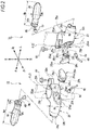
Fig. 2 is an exploded perspective view of the winker shown inFig. 1 . - Hereinafter, a winker of a saddle-type vehicle according to an embodiment of the present invention will be described with reference to
Figs. 1 and2 . The drawings should be seen based on a direction of reference numerals. In the drawings, the front side of the vehicle is denoted as Fr, the rear side is denoted as Rr, the left side is denoted as L, the right side is denoted as R, the upper side is denoted as U, and the lower side is denoted as D. - A vehicle body 2 (only a
front fork 4 is shown) of a motorcycle (not shown) which is an example of the saddle-type vehicle, is generally provided with a total of fourwinkers 10 for emitting light to indicate a turning direction of the vehicle on both left and right sides at front and rear of the vehicle. As shown inFigs. 1 and2 , in the front side of the vehicle, awinker 10 is provided on each of left and right front forks 4 (inFig. 1 , only one at the left side is shown) for supporting a front wheel (not shown). - The
winker 10 is attached to each of the left and rightfront forks 4 so as to extend outward in a vehicle width direction. Thewinker 10 includes aholder 20 which is attached to afront fork 4, awinker body 30 which is attached to one end portion of theholder 20 via asupport base part 30a and includes an indicatingpart 30b configured to emit light to indicate a turning direction of the vehicle and aharness 40 which is led out from thewinker body 30. - In the
winker body 30, an LED light source is used for the indicatingpart 30b. Thewinker body 30 has a width Ww longer than a height Wh thereof and is provided to extend in the vehicle width direction. - The
winker body 30 is fixed to theholder 20 by pushing thesupport base part 30a into anattachment part 20e of theholder 20. - The
harness 40 includes a vehiclebody side harness 40b and awinker side harness 40w. The vehiclebody side harness 40b includes a vehicle bodyside connector part 8a, and thewinker side harness 40w includes a winkerside connector part 8b. Herein, thewinker side harness 40w led out from thesupport base part 30a on a side of thewinker body 30 is formed to be short, and the winkerside connector part 8b is accommodated in ahollow part 20b (described later). The indicatingpart 30b of thewinker 10 is connected to a vehicle power supply system by connecting the vehicle bodyside connector part 8a with the winkerside connector part 8b. In the following description, the vehicle bodyside connector part 8a and the winkerside connector part 8b may be referred to as aconnector part 8. - The
holder 20 is formed with anannular attachment part 20a attached to thefront fork 4, and thehollow part 20b extends in a direction substantially tangential to theattachment part 20a. Thehollow part 20b includes a space 20sp penetrating in a longitudinal direction of thehollow part 20b (substantially the tangential direction of theattachment part 20a). The vehicle bodyside connector part 8a and the winkerside connector part 8b are accommodated in the space 20sp of thehollow part 20b of theholder 20. - The
hollow part 20b of theholder 20 is formed with an opening 20h at an end portion opposite to theattachment part 20e to which thesupport base part 30a of thewinker body 30 is attached. The opening 20h is closed by alid member 20c. - The
lid member 20c includes a lid body part 20cu having a shape corresponding to the opening shape of the opening 20h and a substantially elliptical cylindrical engagement leg 20ci extending from an inner surface side of the lid body part 20cu to an inner side of the space 20sp of thehollow part 20b. A projection strip part 20cj is formed over the entire outer peripheral surface on a distal end side of the engagement leg 20ci. An annular groove 20ig is formed on an inner periphery of an inner wall surface 20iw of thehollow part 20b. - Therefore, as the engagement leg 20ci is pushed into the space 20sp of the
hollow part 20b, the lid body part 20cu closes theopening 20h, and the projection strip part 20cj is engaged in the groove 20ig to be sealed. - The
holder 20 is formed with alower hole 20k in thehollow part 20b. Thelower hole 20k is formed at a lowermost part in a state where thewinker 10 is mounted on the vehicle. Thelower hole 20k is a part from which the vehiclebody side harness 40b including the vehicle bodyside connector part 8a is led out. Thelower hole 20k is formed as a notch structure at an edge part of theopening 20h. A notch-shapedlower hole 20k is also formed in the engagement leg 20ci of thelid member 20c. That is, thelower hole 20k is formed by joining a notch on a side of thehollow part 20b and a notch on a side of thelid member 20c. - The
attachment part 20a for attaching thewinker 10 to thefront fork 4 has an annular shape as a whole, in which a first annular part 20ab and a second annular part 20ac are configured to approach and separate from each other in a circumferential direction. Theattachment part 20a is fastened to an outer periphery of thefront fork 4 by screwing afastening bolt 50 to ajoint part 20m extending radially from the first annular part 20ab and the second annular part 20ac. Accordingly, theholder 20 is fixed to thefront fork 4. Theattachment part 20a has a height Fh substantially equal to a height Hh of thehollow part 20b. That is, theholder 20 has substantially the same height. - The
hollow part 20b of theholder 20 has the height Hh substantially equal to a height Wh of thewinker body 30. Therefore, thewinker 10 is formed into a straight line shape having substantially the same height from theholder 20 to thewinker body 30. - Accordingly, in this embodiment, since the vehicle body
side connector part 8a and the winkerside connector part 8b are accommodated in thehollow part 20b formed in theholder 20 in a state of being coupled to each other, theharness 40 at the winker side can be shortened and a dedicated member for protecting theseconnector parts 8 is not necessary and thus the number of parts can be reduced. Further, since theconnector parts 8 are not exposed, the appearance design of thewinker 10 can be improved. - In this embodiment, since the
holder 20 is formed with theopening 20h at the end portion opposite to theattachment part 20e to which thesupport base part 30a of thewinker body 30 is attached, connection of theconnector parts 8 accommodated in thehollow part 20b is easier. Further, since theopening 20h is closed by thelid member 20c, the waterproof property can be enhanced and the appearance design can be improved. - In this embodiment, since the
holder 20 is formed with thelower hole 20k at the lowermost part in the vehicle mounted state, through which the vehiclebody side harness 40b including the vehicle bodyside connector part 8a is led out, the moisture accumulated in the space 20sp can be discharged from thislower hole 20k. Further, since the lead-out position of the vehiclebody side harness 40b is provided at a lower part of theholder 20, the exposure of the vehiclebody side harness 40b can be suppressed and the appearance can be improved. - In this embodiment, since the
winker body 30 includes the LED light source in the indicatingpart 30b and the width Ww thereof is longer than the height Wh thereof, and the height Hh of thehollow part 20b of theholder 20 is substantially the same as the height Wh of thewinker body 30, the appearance is uniform and the design can be improved. Further, air resistance during running can be kept constant and the handling can be satisfactorily performed. - In this embodiment, since the
holder 20 is formed such that the height Hh of thehollow part 20b is substantially the same as the height Fh of theannular attachment part 20a which is fastened and fixed to the outer periphery of thefront fork 4, the width of theattachment part 20a can be increased, and the appearance design can be improved with good fastening to thefront fork 4. - Although an embodiment of the present invention has been described above, the present invention is not limited to this embodiment but can be modified as appropriate.
- For example, in the above embodiment, the winker on the front part of the motorcycle is exemplified, but the present invention is not limited thereto, and a winker at the rear part of the motorcycle can also be applicable. Also, a saddle-type vehicle other than motorcycles or the like can be applicable.
- Although the
holder 20 is configured to be attached to thefront fork 4, the present invention is not limited thereto, and theholder 20 may be attached to any position of thevehicle body 2. - In addition, in the above embodiment, the
lower hole 20k has a separated structure formed in both thehollow part 20b and thelid member 20c, but the present invention is not limited thereto, and a through hole may be formed in either thehollow part 20b or thelid member 20c. The attaching structure of thehollow part 20b and thelid member 20c and the attaching structure of thehollow part 20b and thewinker body 30 are not limited to the structures shown the drawings. - A winker (10) includes a holder (20) which is attached to a vehicle body (2), a winker body (30) which is attached to one end portion of the holder (20) via a support base part (30a) and includes an indicating part (30b) configured to emit light to indicate a turning direction of a vehicle, and a harness (40) which is led out from the winker body (30). The harness (40) includes a winker side connector part (8b) coupled to a vehicle body side connector part (8a). The holder (20) includes a hollow part (20b) having a space (20sp) therein. The vehicle body side connector part (8a) and the winker side connector part (8b) are accommodated in the hollow part (20b) in a state of being coupled to each other.
Claims (5)
- A winker (10) comprising:a holder (20) which is attached to a vehicle body (2);a winker body (30) which is attached to one end portion of the holder (20) via a support base part (30a) and includes an indicating part (30b) configured to emit light to indicate a turning direction of a vehicle; anda harness (40) which is led out from the winker body (30),wherein the harness (40) includes a winker side connector part (8b) coupled to a vehicle body side connector part (8a),wherein the holder (20) includes a hollow part (20b) having a space (20sp) therein, andwherein the vehicle body side connector part (8a) and the winker side connector part (8b) are accommodated in the hollow part (20b) in a state of being coupled to each other.
- The winker (10) according to claim 1,
wherein the holder (20) is formed with an opening (20h) at an end portion opposite to an attachment part (20e) to which the support base part (30a) of the winker body (30) is attached; and
wherein the opening (20h) is closed by a lid member (20c). - The winker (10) according to claim 2,
wherein the holder (20) is formed with a lower hole (20k) at a lowermost part in a vehicle mounted state, though which a vehicle body side harness (40b) including the vehicle body side connector part (8a) is led out. - The winker (10) according to any one of claims 1 to 3,
wherein the winker body (30) includes an LED light source in the indicating part (30b) and has a width (Ww) longer than a height (Wh) thereof, and
wherein the hollow part (20b) of the holder (20) has a height (Hh) substantially equal to the height (Wh) of the winker body (30). - The winker (10) according to claim 4,
wherein the holder (20) includes an annular attachment part (20a) which is fastened and fixed to an outer periphery of a front fork (4), and
wherein the attachment part (20a) has a height (Fh) substantially equal to a height (Hh) of the hollow part (20b).
Applications Claiming Priority (1)
| Application Number | Priority Date | Filing Date | Title |
|---|---|---|---|
| JP2017063245A JP6482588B2 (en) | 2017-03-28 | 2017-03-28 | Winka |
Publications (2)
| Publication Number | Publication Date |
|---|---|
| EP3381775A1 true EP3381775A1 (en) | 2018-10-03 |
| EP3381775B1 EP3381775B1 (en) | 2021-01-27 |
Family
ID=61626908
Family Applications (1)
| Application Number | Title | Priority Date | Filing Date |
|---|---|---|---|
| EP18160527.0A Active EP3381775B1 (en) | 2017-03-28 | 2018-03-07 | Winker |
Country Status (2)
| Country | Link |
|---|---|
| EP (1) | EP3381775B1 (en) |
| JP (1) | JP6482588B2 (en) |
Citations (8)
| Publication number | Priority date | Publication date | Assignee | Title |
|---|---|---|---|---|
| JPS57114785U (en) * | 1981-01-09 | 1982-07-16 | ||
| US5499169A (en) * | 1995-05-16 | 1996-03-12 | Chen; Chun-Ming | Rearview mirror lamp circuit assembly |
| US5820254A (en) * | 1996-01-16 | 1998-10-13 | Duenas; Mark | Removable motorcycle light |
| US5938322A (en) * | 1998-08-19 | 1999-08-17 | Whelen Engineering Company, Inc. | Rear-view mirror with forward facing warning light |
| JP2005082051A (en) | 2003-09-09 | 2005-03-31 | Honda Motor Co Ltd | Turn signal equipment |
| US20090237231A1 (en) * | 2008-03-19 | 2009-09-24 | Honda Motor Co., Ltd. | Turn signal indicator lamp apparatus for a motorcycle, and motorcycle including same |
| JP2011255725A (en) | 2010-06-07 | 2011-12-22 | Kawasaki Heavy Ind Ltd | Wiring structure of vehicle |
| JP2014065444A (en) * | 2012-09-27 | 2014-04-17 | Stanley Electric Co Ltd | Directional light for motor cycle |
Family Cites Families (6)
| Publication number | Priority date | Publication date | Assignee | Title |
|---|---|---|---|---|
| JPS5715100Y2 (en) * | 1977-10-13 | 1982-03-29 | ||
| JPS5868447U (en) * | 1981-11-02 | 1983-05-10 | 本田技研工業株式会社 | Motorcycle light assembly |
| JP5465557B2 (en) * | 2010-03-11 | 2014-04-09 | 本田技研工業株式会社 | Vehicle lighting |
| JP5799078B2 (en) * | 2013-12-24 | 2015-10-21 | 本田技研工業株式会社 | Turn signal equipment |
| JP6231921B2 (en) * | 2014-03-26 | 2017-11-15 | 本田技研工業株式会社 | Front cowl structure for saddle-ride type vehicles |
| JP6356627B2 (en) * | 2015-03-31 | 2018-07-11 | 本田技研工業株式会社 | A saddle-ride type vehicle equipped with a blinker |
-
2017
- 2017-03-28 JP JP2017063245A patent/JP6482588B2/en active Active
-
2018
- 2018-03-07 EP EP18160527.0A patent/EP3381775B1/en active Active
Patent Citations (8)
| Publication number | Priority date | Publication date | Assignee | Title |
|---|---|---|---|---|
| JPS57114785U (en) * | 1981-01-09 | 1982-07-16 | ||
| US5499169A (en) * | 1995-05-16 | 1996-03-12 | Chen; Chun-Ming | Rearview mirror lamp circuit assembly |
| US5820254A (en) * | 1996-01-16 | 1998-10-13 | Duenas; Mark | Removable motorcycle light |
| US5938322A (en) * | 1998-08-19 | 1999-08-17 | Whelen Engineering Company, Inc. | Rear-view mirror with forward facing warning light |
| JP2005082051A (en) | 2003-09-09 | 2005-03-31 | Honda Motor Co Ltd | Turn signal equipment |
| US20090237231A1 (en) * | 2008-03-19 | 2009-09-24 | Honda Motor Co., Ltd. | Turn signal indicator lamp apparatus for a motorcycle, and motorcycle including same |
| JP2011255725A (en) | 2010-06-07 | 2011-12-22 | Kawasaki Heavy Ind Ltd | Wiring structure of vehicle |
| JP2014065444A (en) * | 2012-09-27 | 2014-04-17 | Stanley Electric Co Ltd | Directional light for motor cycle |
Also Published As
| Publication number | Publication date |
|---|---|
| JP2018165102A (en) | 2018-10-25 |
| JP6482588B2 (en) | 2019-03-13 |
| EP3381775B1 (en) | 2021-01-27 |
Similar Documents
| Publication | Publication Date | Title |
|---|---|---|
| JP5083895B2 (en) | Motorcycle winker equipment | |
| US9975593B2 (en) | Blinker device | |
| EP2159140B1 (en) | Bicycle wire holding arrangement | |
| US11628904B2 (en) | Grip for a bike | |
| US9050929B2 (en) | LED whip light assembly | |
| EP3263432B1 (en) | Straddled vehicle | |
| US8328399B2 (en) | Turn signal device for saddle-ride type vehicle | |
| EP2949557A1 (en) | Saddle-straddling type motor vehicle | |
| EP3381775B1 (en) | Winker | |
| CN100404356C (en) | Direction indicator light device | |
| CN111164003A (en) | Bicycle stem comprising an electrical device | |
| US6089738A (en) | Lamp unit with an external power supply terminal | |
| EP3333055B1 (en) | Straddled vehicle | |
| US11919598B2 (en) | Bicycle frame lighting system | |
| JP5955722B2 (en) | Direction indicator lamps for motorcycles | |
| JP6167074B2 (en) | Bicycle and battery mounting method | |
| JP2010135110A (en) | Lighting fixture for vehicle | |
| EP2599695B1 (en) | Saddle riding type vehicle | |
| CN100465508C (en) | headlight structure | |
| EP1683714B1 (en) | Structure of front fork and outer foot | |
| CN210235173U (en) | Basket device and vehicle | |
| JP7508046B2 (en) | Lighting equipment | |
| JPH0226082Y2 (en) | ||
| JPS645779Y2 (en) | ||
| KR200389559Y1 (en) | bulb holder for cars |
Legal Events
| Date | Code | Title | Description |
|---|---|---|---|
| PUAI | Public reference made under article 153(3) epc to a published international application that has entered the european phase |
Free format text: ORIGINAL CODE: 0009012 |
|
| STAA | Information on the status of an ep patent application or granted ep patent |
Free format text: STATUS: REQUEST FOR EXAMINATION WAS MADE |
|
| 17P | Request for examination filed |
Effective date: 20180307 |
|
| AK | Designated contracting states |
Kind code of ref document: A1 Designated state(s): AL AT BE BG CH CY CZ DE DK EE ES FI FR GB GR HR HU IE IS IT LI LT LU LV MC MK MT NL NO PL PT RO RS SE SI SK SM TR |
|
| AX | Request for extension of the european patent |
Extension state: BA ME |
|
| REG | Reference to a national code |
Ref country code: DE Ref legal event code: R079 Ref document number: 602018012155 Country of ref document: DE Free format text: PREVIOUS MAIN CLASS: B62J0006000000 Ipc: B62J0006050000 |
|
| GRAP | Despatch of communication of intention to grant a patent |
Free format text: ORIGINAL CODE: EPIDOSNIGR1 |
|
| STAA | Information on the status of an ep patent application or granted ep patent |
Free format text: STATUS: GRANT OF PATENT IS INTENDED |
|
| RIC1 | Information provided on ipc code assigned before grant |
Ipc: B60Q 1/34 20060101ALI20200811BHEP Ipc: B62J 6/05 20200101AFI20200811BHEP |
|
| INTG | Intention to grant announced |
Effective date: 20200915 |
|
| RAP1 | Party data changed (applicant data changed or rights of an application transferred) |
Owner name: HONDA MOTOR CO., LTD. |
|
| GRAS | Grant fee paid |
Free format text: ORIGINAL CODE: EPIDOSNIGR3 |
|
| GRAA | (expected) grant |
Free format text: ORIGINAL CODE: 0009210 |
|
| STAA | Information on the status of an ep patent application or granted ep patent |
Free format text: STATUS: THE PATENT HAS BEEN GRANTED |
|
| AK | Designated contracting states |
Kind code of ref document: B1 Designated state(s): AL AT BE BG CH CY CZ DE DK EE ES FI FR GB GR HR HU IE IS IT LI LT LU LV MC MK MT NL NO PL PT RO RS SE SI SK SM TR |
|
| REG | Reference to a national code |
Ref country code: GB Ref legal event code: FG4D |
|
| REG | Reference to a national code |
Ref country code: CH Ref legal event code: EP |
|
| REG | Reference to a national code |
Ref country code: AT Ref legal event code: REF Ref document number: 1358114 Country of ref document: AT Kind code of ref document: T Effective date: 20210215 |
|
| REG | Reference to a national code |
Ref country code: IE Ref legal event code: FG4D |
|
| REG | Reference to a national code |
Ref country code: DE Ref legal event code: R096 Ref document number: 602018012155 Country of ref document: DE |
|
| REG | Reference to a national code |
Ref country code: NL Ref legal event code: MP Effective date: 20210127 |
|
| REG | Reference to a national code |
Ref country code: LT Ref legal event code: MG9D |
|
| REG | Reference to a national code |
Ref country code: AT Ref legal event code: MK05 Ref document number: 1358114 Country of ref document: AT Kind code of ref document: T Effective date: 20210127 |
|
| PG25 | Lapsed in a contracting state [announced via postgrant information from national office to epo] |
Ref country code: PT Free format text: LAPSE BECAUSE OF FAILURE TO SUBMIT A TRANSLATION OF THE DESCRIPTION OR TO PAY THE FEE WITHIN THE PRESCRIBED TIME-LIMIT Effective date: 20210527 Ref country code: NO Free format text: LAPSE BECAUSE OF FAILURE TO SUBMIT A TRANSLATION OF THE DESCRIPTION OR TO PAY THE FEE WITHIN THE PRESCRIBED TIME-LIMIT Effective date: 20210427 Ref country code: HR Free format text: LAPSE BECAUSE OF FAILURE TO SUBMIT A TRANSLATION OF THE DESCRIPTION OR TO PAY THE FEE WITHIN THE PRESCRIBED TIME-LIMIT Effective date: 20210127 Ref country code: GR Free format text: LAPSE BECAUSE OF FAILURE TO SUBMIT A TRANSLATION OF THE DESCRIPTION OR TO PAY THE FEE WITHIN THE PRESCRIBED TIME-LIMIT Effective date: 20210428 Ref country code: FI Free format text: LAPSE BECAUSE OF FAILURE TO SUBMIT A TRANSLATION OF THE DESCRIPTION OR TO PAY THE FEE WITHIN THE PRESCRIBED TIME-LIMIT Effective date: 20210127 Ref country code: BG Free format text: LAPSE BECAUSE OF FAILURE TO SUBMIT A TRANSLATION OF THE DESCRIPTION OR TO PAY THE FEE WITHIN THE PRESCRIBED TIME-LIMIT Effective date: 20210427 Ref country code: LT Free format text: LAPSE BECAUSE OF FAILURE TO SUBMIT A TRANSLATION OF THE DESCRIPTION OR TO PAY THE FEE WITHIN THE PRESCRIBED TIME-LIMIT Effective date: 20210127 |
|
| REG | Reference to a national code |
Ref country code: DE Ref legal event code: R084 Ref document number: 602018012155 Country of ref document: DE |
|
| PG25 | Lapsed in a contracting state [announced via postgrant information from national office to epo] |
Ref country code: RS Free format text: LAPSE BECAUSE OF FAILURE TO SUBMIT A TRANSLATION OF THE DESCRIPTION OR TO PAY THE FEE WITHIN THE PRESCRIBED TIME-LIMIT Effective date: 20210127 Ref country code: LV Free format text: LAPSE BECAUSE OF FAILURE TO SUBMIT A TRANSLATION OF THE DESCRIPTION OR TO PAY THE FEE WITHIN THE PRESCRIBED TIME-LIMIT Effective date: 20210127 Ref country code: PL Free format text: LAPSE BECAUSE OF FAILURE TO SUBMIT A TRANSLATION OF THE DESCRIPTION OR TO PAY THE FEE WITHIN THE PRESCRIBED TIME-LIMIT Effective date: 20210127 Ref country code: AT Free format text: LAPSE BECAUSE OF FAILURE TO SUBMIT A TRANSLATION OF THE DESCRIPTION OR TO PAY THE FEE WITHIN THE PRESCRIBED TIME-LIMIT Effective date: 20210127 Ref country code: SE Free format text: LAPSE BECAUSE OF FAILURE TO SUBMIT A TRANSLATION OF THE DESCRIPTION OR TO PAY THE FEE WITHIN THE PRESCRIBED TIME-LIMIT Effective date: 20210127 |
|
| PG25 | Lapsed in a contracting state [announced via postgrant information from national office to epo] |
Ref country code: IS Free format text: LAPSE BECAUSE OF FAILURE TO SUBMIT A TRANSLATION OF THE DESCRIPTION OR TO PAY THE FEE WITHIN THE PRESCRIBED TIME-LIMIT Effective date: 20210527 |
|
| REG | Reference to a national code |
Ref country code: DE Ref legal event code: R097 Ref document number: 602018012155 Country of ref document: DE |
|
| PG25 | Lapsed in a contracting state [announced via postgrant information from national office to epo] |
Ref country code: SM Free format text: LAPSE BECAUSE OF FAILURE TO SUBMIT A TRANSLATION OF THE DESCRIPTION OR TO PAY THE FEE WITHIN THE PRESCRIBED TIME-LIMIT Effective date: 20210127 Ref country code: EE Free format text: LAPSE BECAUSE OF FAILURE TO SUBMIT A TRANSLATION OF THE DESCRIPTION OR TO PAY THE FEE WITHIN THE PRESCRIBED TIME-LIMIT Effective date: 20210127 Ref country code: CZ Free format text: LAPSE BECAUSE OF FAILURE TO SUBMIT A TRANSLATION OF THE DESCRIPTION OR TO PAY THE FEE WITHIN THE PRESCRIBED TIME-LIMIT Effective date: 20210127 Ref country code: MC Free format text: LAPSE BECAUSE OF FAILURE TO SUBMIT A TRANSLATION OF THE DESCRIPTION OR TO PAY THE FEE WITHIN THE PRESCRIBED TIME-LIMIT Effective date: 20210127 |
|
| REG | Reference to a national code |
Ref country code: CH Ref legal event code: PL |
|
| PG25 | Lapsed in a contracting state [announced via postgrant information from national office to epo] |
Ref country code: SK Free format text: LAPSE BECAUSE OF FAILURE TO SUBMIT A TRANSLATION OF THE DESCRIPTION OR TO PAY THE FEE WITHIN THE PRESCRIBED TIME-LIMIT Effective date: 20210127 Ref country code: DK Free format text: LAPSE BECAUSE OF FAILURE TO SUBMIT A TRANSLATION OF THE DESCRIPTION OR TO PAY THE FEE WITHIN THE PRESCRIBED TIME-LIMIT Effective date: 20210127 Ref country code: RO Free format text: LAPSE BECAUSE OF FAILURE TO SUBMIT A TRANSLATION OF THE DESCRIPTION OR TO PAY THE FEE WITHIN THE PRESCRIBED TIME-LIMIT Effective date: 20210127 |
|
| PLBE | No opposition filed within time limit |
Free format text: ORIGINAL CODE: 0009261 |
|
| STAA | Information on the status of an ep patent application or granted ep patent |
Free format text: STATUS: NO OPPOSITION FILED WITHIN TIME LIMIT |
|
| REG | Reference to a national code |
Ref country code: BE Ref legal event code: MM Effective date: 20210331 |
|
| 26N | No opposition filed |
Effective date: 20211028 |
|
| PG25 | Lapsed in a contracting state [announced via postgrant information from national office to epo] |
Ref country code: ES Free format text: LAPSE BECAUSE OF FAILURE TO SUBMIT A TRANSLATION OF THE DESCRIPTION OR TO PAY THE FEE WITHIN THE PRESCRIBED TIME-LIMIT Effective date: 20210127 Ref country code: FR Free format text: LAPSE BECAUSE OF NON-PAYMENT OF DUE FEES Effective date: 20210327 Ref country code: IE Free format text: LAPSE BECAUSE OF NON-PAYMENT OF DUE FEES Effective date: 20210307 Ref country code: LI Free format text: LAPSE BECAUSE OF NON-PAYMENT OF DUE FEES Effective date: 20210331 Ref country code: LU Free format text: LAPSE BECAUSE OF NON-PAYMENT OF DUE FEES Effective date: 20210307 Ref country code: AL Free format text: LAPSE BECAUSE OF FAILURE TO SUBMIT A TRANSLATION OF THE DESCRIPTION OR TO PAY THE FEE WITHIN THE PRESCRIBED TIME-LIMIT Effective date: 20210127 Ref country code: CH Free format text: LAPSE BECAUSE OF NON-PAYMENT OF DUE FEES Effective date: 20210331 |
|
| PG25 | Lapsed in a contracting state [announced via postgrant information from national office to epo] |
Ref country code: SI Free format text: LAPSE BECAUSE OF FAILURE TO SUBMIT A TRANSLATION OF THE DESCRIPTION OR TO PAY THE FEE WITHIN THE PRESCRIBED TIME-LIMIT Effective date: 20210127 |
|
| PG25 | Lapsed in a contracting state [announced via postgrant information from national office to epo] |
Ref country code: IT Free format text: LAPSE BECAUSE OF FAILURE TO SUBMIT A TRANSLATION OF THE DESCRIPTION OR TO PAY THE FEE WITHIN THE PRESCRIBED TIME-LIMIT Effective date: 20210127 |
|
| PG25 | Lapsed in a contracting state [announced via postgrant information from national office to epo] |
Ref country code: IS Free format text: LAPSE BECAUSE OF FAILURE TO SUBMIT A TRANSLATION OF THE DESCRIPTION OR TO PAY THE FEE WITHIN THE PRESCRIBED TIME-LIMIT Effective date: 20210527 |
|
| PG25 | Lapsed in a contracting state [announced via postgrant information from national office to epo] |
Ref country code: BE Free format text: LAPSE BECAUSE OF NON-PAYMENT OF DUE FEES Effective date: 20210331 |
|
| GBPC | Gb: european patent ceased through non-payment of renewal fee |
Effective date: 20220307 |
|
| PG25 | Lapsed in a contracting state [announced via postgrant information from national office to epo] |
Ref country code: GB Free format text: LAPSE BECAUSE OF NON-PAYMENT OF DUE FEES Effective date: 20220307 |
|
| PG25 | Lapsed in a contracting state [announced via postgrant information from national office to epo] |
Ref country code: NL Free format text: LAPSE BECAUSE OF NON-PAYMENT OF DUE FEES Effective date: 20210127 Ref country code: CY Free format text: LAPSE BECAUSE OF FAILURE TO SUBMIT A TRANSLATION OF THE DESCRIPTION OR TO PAY THE FEE WITHIN THE PRESCRIBED TIME-LIMIT Effective date: 20210127 |
|
| PG25 | Lapsed in a contracting state [announced via postgrant information from national office to epo] |
Ref country code: HU Free format text: LAPSE BECAUSE OF FAILURE TO SUBMIT A TRANSLATION OF THE DESCRIPTION OR TO PAY THE FEE WITHIN THE PRESCRIBED TIME-LIMIT; INVALID AB INITIO Effective date: 20180307 |
|
| PG25 | Lapsed in a contracting state [announced via postgrant information from national office to epo] |
Ref country code: MK Free format text: LAPSE BECAUSE OF FAILURE TO SUBMIT A TRANSLATION OF THE DESCRIPTION OR TO PAY THE FEE WITHIN THE PRESCRIBED TIME-LIMIT Effective date: 20210127 |
|
| PG25 | Lapsed in a contracting state [announced via postgrant information from national office to epo] |
Ref country code: TR Free format text: LAPSE BECAUSE OF FAILURE TO SUBMIT A TRANSLATION OF THE DESCRIPTION OR TO PAY THE FEE WITHIN THE PRESCRIBED TIME-LIMIT Effective date: 20210127 |
|
| PG25 | Lapsed in a contracting state [announced via postgrant information from national office to epo] |
Ref country code: MT Free format text: LAPSE BECAUSE OF FAILURE TO SUBMIT A TRANSLATION OF THE DESCRIPTION OR TO PAY THE FEE WITHIN THE PRESCRIBED TIME-LIMIT Effective date: 20210127 |
|
| PGFP | Annual fee paid to national office [announced via postgrant information from national office to epo] |
Ref country code: DE Payment date: 20260219 Year of fee payment: 9 |