EP3381742A1 - Seating sensor - Google Patents
Seating sensor Download PDFInfo
- Publication number
- EP3381742A1 EP3381742A1 EP17189881.0A EP17189881A EP3381742A1 EP 3381742 A1 EP3381742 A1 EP 3381742A1 EP 17189881 A EP17189881 A EP 17189881A EP 3381742 A1 EP3381742 A1 EP 3381742A1
- Authority
- EP
- European Patent Office
- Prior art keywords
- fall
- positioning
- preventing
- holder
- base portion
- Prior art date
- Legal status (The legal status is an assumption and is not a legal conclusion. Google has not performed a legal analysis and makes no representation as to the accuracy of the status listed.)
- Granted
Links
Images


Classifications
-
- B—PERFORMING OPERATIONS; TRANSPORTING
- B60—VEHICLES IN GENERAL
- B60N—SEATS SPECIALLY ADAPTED FOR VEHICLES; VEHICLE PASSENGER ACCOMMODATION NOT OTHERWISE PROVIDED FOR
- B60N2/00—Seats specially adapted for vehicles; Arrangement or mounting of seats in vehicles
- B60N2/70—Upholstery springs ; Upholstery
- B60N2/7094—Upholstery springs
-
- B—PERFORMING OPERATIONS; TRANSPORTING
- B60—VEHICLES IN GENERAL
- B60N—SEATS SPECIALLY ADAPTED FOR VEHICLES; VEHICLE PASSENGER ACCOMMODATION NOT OTHERWISE PROVIDED FOR
- B60N2/00—Seats specially adapted for vehicles; Arrangement or mounting of seats in vehicles
- B60N2/002—Seats provided with an occupancy detection means mounted therein or thereon
- B60N2/0021—Seats provided with an occupancy detection means mounted therein or thereon characterised by the type of sensor or measurement
- B60N2/003—Seats provided with an occupancy detection means mounted therein or thereon characterised by the type of sensor or measurement characterised by the sensor mounting location in or on the seat
- B60N2/0031—Seats provided with an occupancy detection means mounted therein or thereon characterised by the type of sensor or measurement characterised by the sensor mounting location in or on the seat mounted on the frame
-
- B—PERFORMING OPERATIONS; TRANSPORTING
- B60—VEHICLES IN GENERAL
- B60N—SEATS SPECIALLY ADAPTED FOR VEHICLES; VEHICLE PASSENGER ACCOMMODATION NOT OTHERWISE PROVIDED FOR
- B60N2210/00—Sensor types, e.g. for passenger detection systems or for controlling seats
- B60N2210/40—Force or pressure sensors
- B60N2210/46—Electric switches
Definitions
- This invention relates to a seating sensor.
- the seating sensor includes a holder that is placed on a support member (S-shaped spring) disposed under a cushion member of a seat cushion of a vehicle to support the cushion member, and a sheet-shaped sensor body that is placed on the holder and detects information of a load applied from the cushion member.
- the sensor body is fixed to the holder by a pin-like rivet or clip that penetrates the sensor body in the thickness direction thereof.
- the object of the invention is achieved by a seating sensor having the features of claim 1.
- a seating sensor includes: a holder including a first fall-off preventing portion and a first positioning portion, and being mountable on a seat cushion of a vehicle; and a sensor body mounted on the holder and including a second fall-off preventing portion engaged with the first fall-off preventing portion and configured to restrain fall-off of the first fall-off preventing portion from the holder in a predetermined fall-off preventing direction and a second positioning portion engaged with the first positioning portion and configured to restrain a positional deviation of the first positioning portion relative to the holder in a direction intersecting with the fall-off preventing direction, the sensor body being configured to detect information of a load applied to the seat cushion.
- engagement of the first fall-off preventing portion with the second fall-off preventing portion may suppress the sensor body from falling off from the holder in the fall-off preventing direction
- engagement of the first positioning portion with the second positioning portion may suppress the sensor body from being positionally deviated relative to the holder in a direction intersecting with the fall-off preventing direction
- the seating sensor includes a plurality of sets, each of which is formed by the first positioning portion and the second positioning portion.
- a plurality of pairs of the first positioning portion and the second positioning portion restrain the positional deviation of the sensor body relative to the holder so that, for example, the rotation of the sensor body relative to the holder around one set of the first positioning portion and the second positioning portion may be restrained.
- the first fall-off preventing portion is a base portion and a lid portion which are provided in parallel in the fall-off preventing direction
- the second fall-off preventing portion is an interposing portion sandwiched between the base portion and the lid portion in the fall-off preventing direction.
- the sensor body may be suppressed from falling off from the holder with a very simple structure in which the interposing portion is sandwiched between the base portion and the lid portion.
- the first positioning portion is a positioning projection provided to protrude from any one of the base portion and the lid portion in the fall-off preventing direction
- the second positioning portion is a positioning recess which is formed through the interposing portion in the fall-off preventing direction to face the positioning projection and into which the positioning projection is inserted.
- the sensor body may be suppressed from being positionally deviated relative to the holder with a very simple structure in which the positioning projection is inserted into the positioning recess.
- the base portion is fixedly provided on the holder, the lid portion is rotatably connected to the base portion via a flexible portion, and the seating sensor includes a fitting claw provided to protrude from one of the base portion and the lid portion, and a fitting receiving portion provided on the other one of the base portion and the lid portion and having a fitting hole formed therein so as to enable the fitting claw to be fitted thereto at a rotational position where the base portion and the lid portion are arranged in parallel in the fall-off preventing direction.
- the sensor body when the sensor body is assembled to the holder, the sensor body is positioned relative to the holder by engaging the first positioning portion with the second positioning portion at the rotational position where the lid portion is detached from the base portion in the fall-off preventing direction. Then, by rotating the lid portion around the flexible portion up to the rotational position where the base portion and the lid portion are arranged in parallel in the fall-off preventing direction so as to fit the fitting claw into the fitting hole, the lid portion is fixed at the corresponding rotational position so that the interposing portion is sandwiched between the lid portion and the base portion. As a result, the sensor body is suppressed from falling off from the holder in the fall-off preventing direction. In this manner, the assembly of the sensor body to the holder may be further facilitated.
- the other one of the base portion and the lid portion, which is not provided with the positioning projection has a relief hole formed therein, into which a tip end portion of the positioning projection penetrating the positioning recess is inserted.
- the tip end portion of the positioning projection penetrating the positioning recess may be inserted into the relief hole while the base portion or the lid portion may be brought into close contact with the interposing portion.
- the sensor body may be suppressed from being positionally deviated relative to the holder in the fall-off preventing direction.
- the base portion and the lid portion are integrally provided in the holder.
- an increase in the number of components may be suppressed since the base portion and the lid portion are integrally provided in the holder.
- This invention is effective in suppressing a sensor body from falling off from a holder.
- a seating sensor An exemplary embodiment of a seating sensor will be described below. Further, the forward and rearward direction of a vehicle will be referred to as a "longitudinal direction.”
- a lower rail 2 is fixed to a floor 1 of the vehicle in a state of extending in the longitudinal direction and an upper rail 3 is connected to the lower rail 2 to be movable in the longitudinal direction with respect to the lower rail 2.
- both the lower rails 2 and the upper rails 3 are arranged in pairs in the width direction (the direction orthogonal to the plane of the sheet of Fig. 1).
- FIG. 1 illustrates the pair arranged on the right side in the state of facing the front direction.
- a seat 5 is fixed to and supported on the opposite upper rails 3 to form a seating portion for an occupant.
- the seat 5 includes a seat cushion 6 that forms a seating surface and a seat back 7 that is tiltably (pivotally) supported at the rear end portion of the sheet cushion 6.
- the seat cushion 6 includes a cushion frame 10 that forms the frame of the seat cushion 6 and a cushion member 20 that covers the cushion frame 10.
- the cushion frame 10 includes a pair of cushion side frames 11 that are arranged side by side in the width direction to be placed on the opposite upper rails 3 in the width direction and made of, for example, a metal plate.
- the cushion frame 10 includes a substantially cylindrical front connection rod 12 that extends in the width direction and connects the front portions of the opposite cushion side frames 11 to each other, and a substantially cylindrical rear connection rod 13 that extends in the width direction and connects the rear portions of the opposite cushion side frames 11 to each other.
- a plurality of S-shaped springs 14 basically extending in the longitudinal direction are suspended between the front connection rod 12 and the rear connection rod 13 in a state of being spaced apart from each other in the width direction.
- the plurality of S-shaped springs 14 constitute a support member SU.
- the cushion member 20 is supported by the support member SU in a state of covering the entire cushion frame 10 from above.
- a seating sensor 30 is mounted (mountable) on the support member SU.
- the seating sensor 30 includes a holder 31 mounted on the support member SU in a state of being sandwiched between the cushion member 20 and the support member SU.
- the holder 31 is provided with a substantially rectangular dish-shaped pedestal portion 32 extending in the longitudinal direction.
- the holder 31 is also provided with a substantially rectangular plate-shaped base portion 33 that protrudes rearward from the rear end of the pedestal portion 32.
- the dimension in the width direction of the base portion 33 is set to be equal to the width of an opening in the pedestal portion 32 in the width direction.
- the upper surface of the base portion 33 is widened rearward in a state where the upper surface of the base portion is connected to an opening end surface of the pedestal portion 32 to be substantially flush with the opening end surface.
- the holder 31 is provided with positioning projections 34 having a substantially columnar shape as a pair of front and rear first positioning portions that protrude upward (fall-off preventing direction) on each of both widthwise edges of the base portion 33.
- a substantially triangular fitting claw 35 protrudes at an intermediate portion in the longitudinal direction of an end face on one side (the right side in the figure) in the width direction of the base portion 33.
- a substantially rectangular plate-shaped lid portion 37 is connected to an end face of the other side (the left side in the figure) in the width direction of the base portion 33 via a thin flexible portion 36 that forms a hinge.
- the dimension in the width direction of the lid portion 37 is set to be equal to the dimension in the width direction of the base portion 33 including the fitting claw 35, and the dimension in the longitudinal direction of the lid portion 37 is set to be equal to the dimension in the longitudinal direction of the base portion 33.
- a pair of front and rear relief holes 37a having a substantially circular shape are formed through the opposite widthwise edges of the lid portion 37.
- the inner diameter of each of the relief holes 37a is set to be slightly larger than the diameter of each of the positioning projections 34.
- the lid portion 37 when the lid portion 37 is rotated around the flexible portion 36 until the lid portion is positioned above the base portion 33, the positioning projections 34 are respectively loosely fitted into the relief holes 37a and the fitting receiving portion 38 is elastically deformed so that the fitting receiving portion 38 rides over the fitting claw 35 and the fitting claw 35 is fitted into the fitting hole 38a (so-called snap fit).
- the lid portion 37 is arranged above the base portion 33 (in the fall-off preventing direction) in parallel to the base portion 33 in a state of being fixed to the base portion 33.
- the base portion 33 and the lid portion 37 constitute a first fall-off preventing portion.
- a sensor body 40 that extends in the longitudinal direction along the pedestal portion 32 is placed on the holder 31.
- the sensor body 40 is configured with a membrane switch obtained by laminating, via an insulating spacer (e.g., a polyester film), a pair of contact sheets, each of which is obtained by printing a conductive ink (e.g., silver paste or carbon paste) on an insulating film (e.g., a polyester film).
- an insulating spacer e.g., a polyester film
- a pair of contact sheets each of which is obtained by printing a conductive ink (e.g., silver paste or carbon paste) on an insulating film (e.g., a polyester film).
- a detection unit 41 in a shape of substantially continuous multi-circles is provided in the sensor body 40 to extend in the longitudinal direction in the pedestal portion 32.
- the sensor body 40 detects information of a load applied from the cushion member 20 by the detection unit 41.
- the pedestal portion 32 functions as a pressure receiving surface of the load.
- the sensor body 40 is provided with a substantially band-shaped connection portion 42 that is connected to the rear end of the detection unit 41 and extends rearward.
- a connector 43 to be connected to, for example, a control device is provided at the tip end of the side that is located away from the detection unit 41 of the connection portion 42.
- the sensor body 40 is provided with an interposing portion 44 serving as a second fall-off preventing portion.
- the interposing portion 44 is formed by widening the width of the connection portion 42 at a position in the longitudinal direction on the base portion 33.
- the dimensions in the width direction and the longitudinal direction of the interposing portion 44 are set to be equal to the dimensions in the width direction and the longitudinal direction of the base portion 33, respectively.
- substantially circular positioning recesses 44a serving as a pair of front and rear second positioning portions are formed to penetrate therethrough.
- Each of the positioning recesses 44a is formed to penetrate in the vertical direction (fall-off preventing direction) to face each of the positioning projections 34, and the diameter of the positioning recesses 44a is set to be equal to the diameter of the positioning projections 34.
- the interposing portion 44 is sandwiched between the base portion 33 and the lid portion 37 arranged in parallel in the vertical direction, fall-off of the sensor body 40 from the holder 31 in the corresponding direction is restrained.
- the positional deviation of the sensor body 40 relative to the holder 31 in an arbitrary direction (a direction intersecting with the fall-off preventing direction) along the base portion 33 is restrained by inserting (fitting) the positioning projections 34 into the positioning recesses 44a.
- a cushion member 49 made of, for example, an elastic material is interposed between the pedestal portion 32 and the detection portion 41 so as to form a shape of substantially continuous multi-circles in conformity with the detection portion 41.
- the thickness of the cushion member 49 is set to be equal to the depth of the pedestal portion 32.
- substantially quadrangular prism-shaped positioning projections 52 serving as the first positioning portion may be provided to protrude upward (fall-off preventing direction) on each of the widthwise opposite edges of a base portion 51 of a holder 50 similar to the holder 31.
- a pair of positioning recesses 56a which are opposite each other and are cut out in a substantially quadrangular shape in the width direction to be matched with the opposite positioning projections 52, may be formed in the interposing portion 56 of a sensor body 55 similar to the sensor body 40. Even in this case, the sensor body 55 may be suppressed from being positionally deviated relative to the holder 50 with a very simple structure in which the positioning projections 52 are inserted into the positioning recesses 56a.
- the cushion member 49 may be bonded to the upper surface of the pedestal portion 32 or may be bonded to the lower surface of the detection portion 41, for example, by an adhesive.
- the cushion member 49 may be omitted.
- the base portion 33 and the lid portion 37 may be a separate member (separate component) from the holder 31.
- the base portion 33 may be fixed to the holder 31 by a proper fixing member.
- the lid portion 37 may be connected to the base portion 33 by a separate flexible portion 36.
- the fitting claw 35 and the fitting receiving portion 38 may be separate members from the base portion 33 and the lid portion 37, respectively.
- the base portion 33 and the lid portion 37 may be integrally formed and arranged in parallel in the vertical direction (fall-off preventing direction). That is, a connection portion that integrally connects the base portion 33 and the lid portion 37 to each other may be provided instead of the flexible portion 36, and a connection portion that integrally connects the base portion 33 and the lid portion 37 to each other may be provided, instead of the fitting claw 35 and the fitting receiving portion 38.
- the positioning projections 34 and the relief holes 37a are provided in the base portion 33 and the lid portion 37, respectively, but the relationship therebetween may be reversed. That is, the relief holes and the positioning projections may be provided in the base portion 33 and the lid portion 37, respectively.
- the relief hole 37a of the lid portion 37 may be omitted as long as the parallel arrangement of the base portion 33 and the lid portion 37 are not hindered.
- the fitting claw 35 and the fitting receiving portion 38 are provided in the base portion 33 and the lid portion 37, respectively, but the relationship therebetween may be reversed. That is, the fitting receiving portion and the fitting claw may be provided in the base portion 33 and the lid portion 37, respectively.
- the interposing portion 44 obtained by widening the width of the connection portion 42 is adopted, but, for example, the interposing portion in which the width dimension of the connection portion 42 is maintained may be adopted.
- the positioning projections may have a polygonal pillar shape or a pyramidal shape.
- positioning recesses may be formed to correspond to the shape of the positioning projections.
- the number of pairs of positioning projections 34 and positioning recesses 44a to be inserted is arbitrary. However, it may be more desirable to provide a plurality of sets of positioning projections 34 and positioning recesses 44a. Further, the relief holes 37a may be formed in the lid portion 37 in the number corresponding to the number of sets of positioning projections 34 and positioning recesses 44a.
- the fall-off preventing direction is made to coincide with the vertical direction, but may be any other direction.
- the lid portion 37 and the peripheral structure thereof may be omitted. Further, a positioning projection provided with a turn-back portion for preventing the fall-off of the positioning recesses 44a at the tip end may be adopted. In this case, since the interposing portion 44 is sandwiched between the base portion and the turn-back portion of the positioning projection, the sensor body 40 is suppressed from falling off from the holder. By using the positioning projection as a first fall-off preventing portion in this manner, the structure may be further simplified.
- the seating sensor may be a seating sensor mounted on the upper portion of the cushion member 30.
- the sensor body is a membrane switch formed in a film shape.
- the sensor body is a membrane switch formed in a film shape, it is possible to make the sensor body thinner and to further improve drip-proof performance and dust-proof performance.
- a seating sensor (30) includes: a holder (31, 50) including a first fall-off preventing portion (33, 51) and a first positioning portion (34, 52), and being mountable on a seat cushion (6) of a vehicle; and a sensor body (40, 55) mounted on the holder and including a second fall-off preventing portion (44, 56) engaged with the first fall-off preventing portion and configured to restrain fall-off of the first fall-off preventing portion from the holder in a predetermined fall-off preventing direction and a second positioning portion (44a, 56a) engaged with the first positioning portion and configured to restrain a positional deviation of the first positioning portion relative to the holder in a direction intersecting with the fall-off preventing direction, the sensor body being configured to detect information of a load applied to the seat cushion.
Landscapes
- Engineering & Computer Science (AREA)
- Aviation & Aerospace Engineering (AREA)
- Transportation (AREA)
- Mechanical Engineering (AREA)
- Seats For Vehicles (AREA)
- Chair Legs, Seat Parts, And Backrests (AREA)
Description
- This invention relates to a seating sensor.
- As a seating sensor, for example, the seating sensor disclosed in
CN 203331881 U (seeFig. 3 thereof) has been known in the related art. The seating sensor includes a holder that is placed on a support member (S-shaped spring) disposed under a cushion member of a seat cushion of a vehicle to support the cushion member, and a sheet-shaped sensor body that is placed on the holder and detects information of a load applied from the cushion member. The sensor body is fixed to the holder by a pin-like rivet or clip that penetrates the sensor body in the thickness direction thereof. - In
CN 203331881 U , since a substantially cylindrical rivet or clip only penetrates the sensor body, there is a possibility that the sensor body may come out of the rivet or clip and fall off from the holder. - Thus, a need exists for a seating sensor capable of suppressing a sensor body from falling off from a holder.
- It is therefore the object of the invention to provide a seating sensor whose mountability is improved.
- The object of the invention is achieved by a seating sensor having the features of claim 1.
- Further advantageous developments of the invention are defined in the dependent claims.
- A seating sensor according to an aspect of this invention includes: a holder including a first fall-off preventing portion and a first positioning portion, and being mountable on a seat cushion of a vehicle; and a sensor body mounted on the holder and including a second fall-off preventing portion engaged with the first fall-off preventing portion and configured to restrain fall-off of the first fall-off preventing portion from the holder in a predetermined fall-off preventing direction and a second positioning portion engaged with the first positioning portion and configured to restrain a positional deviation of the first positioning portion relative to the holder in a direction intersecting with the fall-off preventing direction, the sensor body being configured to detect information of a load applied to the seat cushion.
- According to this configuration, engagement of the first fall-off preventing portion with the second fall-off preventing portion may suppress the sensor body from falling off from the holder in the fall-off preventing direction, and engagement of the first positioning portion with the second positioning portion may suppress the sensor body from being positionally deviated relative to the holder in a direction intersecting with the fall-off preventing direction.
- It is preferable that the seating sensor includes a plurality of sets, each of which is formed by the first positioning portion and the second positioning portion.
- According to this preferred configuration, a plurality of pairs of the first positioning portion and the second positioning portion restrain the positional deviation of the sensor body relative to the holder so that, for example, the rotation of the sensor body relative to the holder around one set of the first positioning portion and the second positioning portion may be restrained.
- In the seating sensor, it is preferable that the first fall-off preventing portion is a base portion and a lid portion which are provided in parallel in the fall-off preventing direction, and the second fall-off preventing portion is an interposing portion sandwiched between the base portion and the lid portion in the fall-off preventing direction.
- According to this preferred configuration, the sensor body may be suppressed from falling off from the holder with a very simple structure in which the interposing portion is sandwiched between the base portion and the lid portion.
- In the seating sensor, it is preferable that the first positioning portion is a positioning projection provided to protrude from any one of the base portion and the lid portion in the fall-off preventing direction, and the second positioning portion is a positioning recess which is formed through the interposing portion in the fall-off preventing direction to face the positioning projection and into which the positioning projection is inserted.
- According to this preferred configuration, the sensor body may be suppressed from being positionally deviated relative to the holder with a very simple structure in which the positioning projection is inserted into the positioning recess.
- In the seating sensor, it is preferable that the base portion is fixedly provided on the holder, the lid portion is rotatably connected to the base portion via a flexible portion, and the seating sensor includes a fitting claw provided to protrude from one of the base portion and the lid portion, and a fitting receiving portion provided on the other one of the base portion and the lid portion and having a fitting hole formed therein so as to enable the fitting claw to be fitted thereto at a rotational position where the base portion and the lid portion are arranged in parallel in the fall-off preventing direction.
- According to this preferred configuration, when the sensor body is assembled to the holder, the sensor body is positioned relative to the holder by engaging the first positioning portion with the second positioning portion at the rotational position where the lid portion is detached from the base portion in the fall-off preventing direction. Then, by rotating the lid portion around the flexible portion up to the rotational position where the base portion and the lid portion are arranged in parallel in the fall-off preventing direction so as to fit the fitting claw into the fitting hole, the lid portion is fixed at the corresponding rotational position so that the interposing portion is sandwiched between the lid portion and the base portion. As a result, the sensor body is suppressed from falling off from the holder in the fall-off preventing direction. In this manner, the assembly of the sensor body to the holder may be further facilitated.
- In the seating sensor, it is preferable that the other one of the base portion and the lid portion, which is not provided with the positioning projection, has a relief hole formed therein, into which a tip end portion of the positioning projection penetrating the positioning recess is inserted.
- According to this preferred configuration, when the interposing portion is sandwiched between the base portion and the lid portion by rotating the lid portion around the flexible portion up to the rotational position in which the base portion and the lid portion are arranged in parallel in the fall-off preventing direction, the tip end portion of the positioning projection penetrating the positioning recess may be inserted into the relief hole while the base portion or the lid portion may be brought into close contact with the interposing portion. As a result, the sensor body may be suppressed from being positionally deviated relative to the holder in the fall-off preventing direction.
- In the seating sensor, it is preferable that the base portion and the lid portion are integrally provided in the holder.
- According to this preferred configuration, an increase in the number of components may be suppressed since the base portion and the lid portion are integrally provided in the holder.
- This invention is effective in suppressing a sensor body from falling off from a holder.
- The foregoing, additional features, effects and advantages of this invention will become more apparent from the following detailed description considered with the reference to the accompanying drawings, wherein:
-
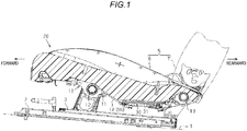
Fig. 1 is a vertical sectional view illustrating the structure of an exemplary embodiment of a seating sensor; -
Fig. 2 is a perspective view illustrating the structure of the seating sensor according to the exemplary embodiment; -
Figs. 3A and 3B are perspective views illustrating the operation of the seating sensor according to the exemplary embodiment; and -
Fig. 4 is a perspective view illustrating the structure of a modification of a seating sensor. - An exemplary embodiment of a seating sensor will be described below. Further, the forward and rearward direction of a vehicle will be referred to as a "longitudinal direction."
- As illustrated in
Fig. 1 , alower rail 2 is fixed to a floor 1 of the vehicle in a state of extending in the longitudinal direction and an upper rail 3 is connected to thelower rail 2 to be movable in the longitudinal direction with respect to thelower rail 2. - In addition, both the
lower rails 2 and the upper rails 3 are arranged in pairs in the width direction (the direction orthogonal to the plane of the sheet ofFig. 1). FIG. 1 illustrates the pair arranged on the right side in the state of facing the front direction. Further, aseat 5 is fixed to and supported on the opposite upper rails 3 to form a seating portion for an occupant. - The
seat 5 includes a seat cushion 6 that forms a seating surface and a seat back 7 that is tiltably (pivotally) supported at the rear end portion of the sheet cushion 6. In addition, the seat cushion 6 includes a cushion frame 10 that forms the frame of the seat cushion 6 and acushion member 20 that covers the cushion frame 10. The cushion frame 10 includes a pair of cushion side frames 11 that are arranged side by side in the width direction to be placed on the opposite upper rails 3 in the width direction and made of, for example, a metal plate. Further, the cushion frame 10 includes a substantially cylindricalfront connection rod 12 that extends in the width direction and connects the front portions of the opposite cushion side frames 11 to each other, and a substantially cylindricalrear connection rod 13 that extends in the width direction and connects the rear portions of the opposite cushion side frames 11 to each other. A plurality of S-shaped springs 14 basically extending in the longitudinal direction are suspended between thefront connection rod 12 and therear connection rod 13 in a state of being spaced apart from each other in the width direction. The plurality of S-shaped springs 14 constitute a support member SU. - The
cushion member 20 is supported by the support member SU in a state of covering the entire cushion frame 10 from above. - A
seating sensor 30 is mounted (mountable) on the support member SU. Theseating sensor 30 includes aholder 31 mounted on the support member SU in a state of being sandwiched between thecushion member 20 and the support member SU. - As illustrated in
Figs. 2 ,3A, and 3B , theholder 31 is provided with a substantially rectangular dish-shaped pedestal portion 32 extending in the longitudinal direction. Theholder 31 is also provided with a substantially rectangular plate-shaped base portion 33 that protrudes rearward from the rear end of thepedestal portion 32. The dimension in the width direction of thebase portion 33 is set to be equal to the width of an opening in thepedestal portion 32 in the width direction. Further, the upper surface of thebase portion 33 is widened rearward in a state where the upper surface of the base portion is connected to an opening end surface of thepedestal portion 32 to be substantially flush with the opening end surface. In addition, theholder 31 is provided withpositioning projections 34 having a substantially columnar shape as a pair of front and rear first positioning portions that protrude upward (fall-off preventing direction) on each of both widthwise edges of thebase portion 33. - A substantially
triangular fitting claw 35 protrudes at an intermediate portion in the longitudinal direction of an end face on one side (the right side in the figure) in the width direction of thebase portion 33. Further, a substantially rectangular plate-shaped lid portion 37 is connected to an end face of the other side (the left side in the figure) in the width direction of thebase portion 33 via a thinflexible portion 36 that forms a hinge. The dimension in the width direction of thelid portion 37 is set to be equal to the dimension in the width direction of thebase portion 33 including thefitting claw 35, and the dimension in the longitudinal direction of thelid portion 37 is set to be equal to the dimension in the longitudinal direction of thebase portion 33. Also, a pair of front andrear relief holes 37a having a substantially circular shape are formed through the opposite widthwise edges of thelid portion 37. The inner diameter of each of therelief holes 37a is set to be slightly larger than the diameter of each of thepositioning projections 34. When thelid portion 37 is rotated about theflexible portion 36 until thelid portion 37 is positioned above thebase portion 33, therelief holes 37a respectively face thepositioning projections 34 and thepositioning projections 34 respectively penetrate therelief holes 37a in the vertical direction (fall-off preventing direction). Further, a substantially door-shapedfitting receiving portion 38 is formed to protrude from an intermediate portion in the longitudinal direction of the edge on the side that is located away from theflexible portion 36 of thelid portion 37. In the fitting receivingportion 38, afitting hole 38a is formed to penetrate the fitting receivingportion 38 in the width direction to face thefitting claw 35 when thelid portion 37 is rotated around theflexible portion 36 to be positioned above thebase portion 33. - Thus, when the
lid portion 37 is rotated around theflexible portion 36 until the lid portion is positioned above thebase portion 33, thepositioning projections 34 are respectively loosely fitted into therelief holes 37a and the fitting receivingportion 38 is elastically deformed so that the fitting receivingportion 38 rides over thefitting claw 35 and thefitting claw 35 is fitted into thefitting hole 38a (so-called snap fit). Thus, thelid portion 37 is arranged above the base portion 33 (in the fall-off preventing direction) in parallel to thebase portion 33 in a state of being fixed to thebase portion 33. Thebase portion 33 and thelid portion 37 constitute a first fall-off preventing portion. - A
sensor body 40 that extends in the longitudinal direction along thepedestal portion 32 is placed on theholder 31. Thesensor body 40 is configured with a membrane switch obtained by laminating, via an insulating spacer (e.g., a polyester film), a pair of contact sheets, each of which is obtained by printing a conductive ink (e.g., silver paste or carbon paste) on an insulating film (e.g., a polyester film). - A
detection unit 41 in a shape of substantially continuous multi-circles is provided in thesensor body 40 to extend in the longitudinal direction in thepedestal portion 32. Thesensor body 40 detects information of a load applied from thecushion member 20 by thedetection unit 41. At this time, thepedestal portion 32 functions as a pressure receiving surface of the load. Further, thesensor body 40 is provided with a substantially band-shapedconnection portion 42 that is connected to the rear end of thedetection unit 41 and extends rearward. For example, aconnector 43 to be connected to, for example, a control device, is provided at the tip end of the side that is located away from thedetection unit 41 of theconnection portion 42. - In addition, the
sensor body 40 is provided with an interposingportion 44 serving as a second fall-off preventing portion. The interposingportion 44 is formed by widening the width of theconnection portion 42 at a position in the longitudinal direction on thebase portion 33. The dimensions in the width direction and the longitudinal direction of the interposingportion 44 are set to be equal to the dimensions in the width direction and the longitudinal direction of thebase portion 33, respectively. Further, in each of the opposite side edges of the interposingportion 44 in the width direction, substantiallycircular positioning recesses 44a serving as a pair of front and rear second positioning portions are formed to penetrate therethrough. Each of thepositioning recesses 44a is formed to penetrate in the vertical direction (fall-off preventing direction) to face each of thepositioning projections 34, and the diameter of thepositioning recesses 44a is set to be equal to the diameter of thepositioning projections 34. - In the
sensor body 40, since the interposingportion 44 is sandwiched between thebase portion 33 and thelid portion 37 arranged in parallel in the vertical direction, fall-off of thesensor body 40 from theholder 31 in the corresponding direction is restrained. In this case, the positional deviation of thesensor body 40 relative to theholder 31 in an arbitrary direction (a direction intersecting with the fall-off preventing direction) along thebase portion 33 is restrained by inserting (fitting) thepositioning projections 34 into the positioning recesses 44a. - Further, a
cushion member 49 made of, for example, an elastic material is interposed between thepedestal portion 32 and thedetection portion 41 so as to form a shape of substantially continuous multi-circles in conformity with thedetection portion 41. The thickness of thecushion member 49 is set to be equal to the depth of thepedestal portion 32. - Next, the action of the exemplary embodiment disclosed here and the effect thereof will be described.
- (1) In the exemplary embodiment, the engagement of the
base portion 33 and thelid portion 37 with the interposingportion 44 may suppress thesensor body 40 from falling off from theholder 31 in the vertical direction (fall-off preventing direction), and the engagement of thepositioning projections 34 with the positioning recesses 44a may suppress thesensor body 40 from being positionally deviated relative to theholder 31 in a direction intersecting with the vertical direction (fall-off preventing direction). Further, for example, the initial positional deviation during the assembly of thesensor body 40 to theholder 31 may be suppressed. The positional deviation and fall-off of thesensor body 40 from theholder 31 may also be suppressed when a tensile force is applied to thesensor body 40. - (2) In the exemplary embodiment, since a plurality of sets of
positioning projections 34 andpositioning recesses 44a restrain the positional deviation of thesensor body 40 relative to theholder 31, for example, the rotation of thesensor body 40 relative to theholder 31 around one set ofpositioning projection 34 andpositioning recess 44a may be restrained. - (3) In the exemplary embodiment, the
sensor body 40 may be suppressed from falling off from theholder 31 with a very simple structure in which the interposingportion 44 is sandwiched between thebase portion 33 and thelid portion 37. - (4) In the exemplary embodiment, the
sensor body 40 may be suppressed from being positionally deviated relative to theholder 31 with a very simple structure in which thepositioning projections 34 is inserted into the positioning recesses 44a. - (5) In the exemplary embodiment, when assembling the
sensor body 40 to theholder 31, thesensor body 40 is positioned relative to theholder 31 by engaging thepositioning projections 34 with the positioning recesses 44a at a rotational position where thelid portion 37 is detached from thebase portion 33 in the vertical direction (fall-off preventing direction), as illustrated inFig. 3A . Then, as illustrated inFig. 3B , thelid portion 37 is rotated around theflexible portion 36 up to a rotational position where thebase portion 33 and thelid portion 37 are arranged in parallel in the vertical direction, and thefitting claw 35 is fitted into thefitting hole 38a, so that thelid portion 37 is fixed at the rotational position and the interposingportion 44 is sandwiched between thelid portion 37 and thebase portion 33. As a result, thesensor body 40 is suppressed from falling off from theholder 31 in the vertical direction. In this manner, the assembly of thesensor body 40 to theholder 31 may be further facilitated. - (6) In the exemplary embodiment, the
lid portion 37 is formed withrelief holes 37a where the tip ends portion of thepositioning projections 34 penetrating the positioning recesses 44a are inserted. Thus, when the interposingportion 44 is sandwiched between thebase portion 33 and thelid portion 37 by rotating thelid portion 37 around theflexible portion 36 up to the rotational position where thebase portion 33 and thelid portion 37 are arranged in parallel in the vertical direction (fall-off preventing direction), the tip end portions of thepositioning projections 34 penetrating the positioning recesses 44a may be inserted into therelief holes 37a, while thelid portion 37 may be brought into close contact with the interposingportion 44. As a result, thesensor body 40 may be suppressed from being positionally deviated in the vertical direction relative to theholder 31. - (7) In the exemplary embodiment, the
base portion 33 and thelid portion 37 are integrally provided in theholder 31 so that an increase in the number of components may be suppressed. - (8) In the exemplary embodiment, since the
lid portion 37, which is on the movable side with respect to thepedestal portion 32 or the like, is arranged above thebase portion 33, the possibility that thesensor body 40 may fall off from theholder 31 may be reduced, even when thelid portion 37 is detached from thebase portion 33. Further, by inserting thepositioning projections 34 protruding from thebase portion 33 into the positioning recesses 44a in the interposingportion 44 from the underside, the possibility that thesensor body 40 may be positionally deviated relative to theholder 31 may be reduced, even when thelid portion 37 is detached from thebase portion 33. - (9) In the exemplary embodiment, by fixing the
sensor body 40 to theholder 31 only with the engagement relationship between theholder 31 and thesensor body 40, for example, other fixing components (a rivet, a clip, an adhesive, and the like) may be omitted, and the number of the components and the cost may be reduced. - (10) In the exemplary embodiment, since the
sensor body 40 is a membrane switch formed in a film shape, it is possible to make thesensor body 40 thinner and to further improve drip-proof performance and dust-proof performance. - Further, the above-described exemplary embodiment may be modified as follows.
- As illustrated in
Fig. 4 , substantially quadrangular prism-shapedpositioning projections 52 serving as the first positioning portion may be provided to protrude upward (fall-off preventing direction) on each of the widthwise opposite edges of abase portion 51 of aholder 50 similar to theholder 31. Further, a pair ofpositioning recesses 56a, which are opposite each other and are cut out in a substantially quadrangular shape in the width direction to be matched with theopposite positioning projections 52, may be formed in the interposingportion 56 of asensor body 55 similar to thesensor body 40. Even in this case, thesensor body 55 may be suppressed from being positionally deviated relative to theholder 50 with a very simple structure in which thepositioning projections 52 are inserted into the positioning recesses 56a. - In the above-described exemplary embodiment, the
cushion member 49 may be bonded to the upper surface of thepedestal portion 32 or may be bonded to the lower surface of thedetection portion 41, for example, by an adhesive. - In the above-described exemplary embodiment, the
cushion member 49 may be omitted. - In the above-described exemplary embodiment, at least one of the
base portion 33 and thelid portion 37 may be a separate member (separate component) from theholder 31. For example, thebase portion 33 may be fixed to theholder 31 by a proper fixing member. Alternatively, thelid portion 37 may be connected to thebase portion 33 by a separateflexible portion 36. Also, thefitting claw 35 and the fitting receivingportion 38 may be separate members from thebase portion 33 and thelid portion 37, respectively. - In the above-described exemplary embodiment, the
base portion 33 and thelid portion 37 may be integrally formed and arranged in parallel in the vertical direction (fall-off preventing direction). That is, a connection portion that integrally connects thebase portion 33 and thelid portion 37 to each other may be provided instead of theflexible portion 36, and a connection portion that integrally connects thebase portion 33 and thelid portion 37 to each other may be provided, instead of thefitting claw 35 and the fitting receivingportion 38. - In the above-described exemplary embodiment, the
positioning projections 34 and therelief holes 37a are provided in thebase portion 33 and thelid portion 37, respectively, but the relationship therebetween may be reversed. That is, the relief holes and the positioning projections may be provided in thebase portion 33 and thelid portion 37, respectively. - In the above-described exemplary embodiment, the
relief hole 37a of thelid portion 37 may be omitted as long as the parallel arrangement of thebase portion 33 and thelid portion 37 are not hindered. - In the above-described exemplary embodiment, the
fitting claw 35 and the fitting receivingportion 38 are provided in thebase portion 33 and thelid portion 37, respectively, but the relationship therebetween may be reversed. That is, the fitting receiving portion and the fitting claw may be provided in thebase portion 33 and thelid portion 37, respectively. - In the above-described exemplary embodiment, the interposing
portion 44 obtained by widening the width of theconnection portion 42 is adopted, but, for example, the interposing portion in which the width dimension of theconnection portion 42 is maintained may be adopted. - In the above-described exemplary embodiment, the positioning projections may have a polygonal pillar shape or a pyramidal shape. In this case, positioning recesses may be formed to correspond to the shape of the positioning projections.
- In the above-described exemplary embodiment, the number of pairs of
positioning projections 34 andpositioning recesses 44a to be inserted is arbitrary. However, it may be more desirable to provide a plurality of sets ofpositioning projections 34 andpositioning recesses 44a. Further, therelief holes 37a may be formed in thelid portion 37 in the number corresponding to the number of sets ofpositioning projections 34 andpositioning recesses 44a. - In the above-described exemplary embodiment, the fall-off preventing direction is made to coincide with the vertical direction, but may be any other direction.
- The
lid portion 37 and the peripheral structure thereof may be omitted. Further, a positioning projection provided with a turn-back portion for preventing the fall-off of the positioning recesses 44a at the tip end may be adopted. In this case, since the interposingportion 44 is sandwiched between the base portion and the turn-back portion of the positioning projection, thesensor body 40 is suppressed from falling off from the holder. By using the positioning projection as a first fall-off preventing portion in this manner, the structure may be further simplified. - The seating sensor may be a seating sensor mounted on the upper portion of the
cushion member 30. - The technical concept that may be understood from the above-described exemplary embodiment and the other examples will be added below.
- In the above-described seating sensor, the sensor body is a membrane switch formed in a film shape.
- According to this configuration, since the sensor body is a membrane switch formed in a film shape, it is possible to make the sensor body thinner and to further improve drip-proof performance and dust-proof performance.
- The principles, preferred embodiment and mode of operation of the present invention have been described in the foregoing specification; however, the invention which is intended to be protected is not to be construed as limited to the particular embodiments disclosed, i.e. all such variations, changes and equivalents which fall under the scope of the present invention as defined in the appended claims are embraced thereby.
- A seating sensor (30) includes: a holder (31, 50) including a first fall-off preventing portion (33, 51) and a first positioning portion (34, 52), and being mountable on a seat cushion (6) of a vehicle; and a sensor body (40, 55) mounted on the holder and including a second fall-off preventing portion (44, 56) engaged with the first fall-off preventing portion and configured to restrain fall-off of the first fall-off preventing portion from the holder in a predetermined fall-off preventing direction and a second positioning portion (44a, 56a) engaged with the first positioning portion and configured to restrain a positional deviation of the first positioning portion relative to the holder in a direction intersecting with the fall-off preventing direction, the sensor body being configured to detect information of a load applied to the seat cushion.
Claims (7)
- A seating sensor (30) comprising:a holder (31, 50) including a first fall-off preventing portion (33, 51) and a first positioning portion (34, 52), and being mountable on a seat cushion (6) of a vehicle; anda sensor body (40, 55) mounted on the holder (31, 50) and including a second fall-off preventing portion (44, 56) engaged with the first fall-off preventing portion (33, 51) and configured to restrain fall-off of the first fall-off preventing portion (33, 51) from the holder (31, 50) in a predetermined fall-off preventing direction and a second positioning portion (44a, 56a) engaged with the first positioning portion (34, 52) and configured to restrain a positional deviation of the first positioning portion (34, 52) relative to the holder (31, 50) in a direction intersecting with the fall-off preventing direction, the sensor body (40, 55) being configured to detect information of a load applied to the seat cushion (6).
- The seating sensor (30) according to claim 1, comprising:a plurality of sets, each of which is formed by the first positioning portion (34, 52) and the second positioning portion (44a, 56a).
- The seating sensor (30) according to claim 1 or 2,
wherein the first fall-off preventing portion (33, 51) is a base portion (33) and a lid portion (37) which are provided in parallel in the fall-off preventing direction, and
the second fall-off preventing portion (44, 56) is an interposing portion (44) sandwiched between the base portion (33) and the lid portion (37) in the fall-off preventing direction. - The seating sensor (30) according to claim 3,
wherein the first positioning portion (34, 52) is a positioning projection (34) provided to protrude from any one of the base portion (33) and the lid portion (37) in the fall-off preventing direction, and
the second positioning portion (44a, 56a) is a positioning recess (44a) which is formed through the interposing portion (44) in the fall-off preventing direction to face the positioning projection (34) and into which the positioning projection (34) is inserted. - The seating sensor (30) according to claim 4,
wherein the base portion (33) is fixedly provided on the holder (31, 50),
the lid portion (37) is rotatably connected to the base portion (33) via a flexible portion (36), and
the seating sensor (30) further comprises
a fitting claw (35) provided to protrude from one of the base portion (33) and the lid portion (37), and
a fitting receiving portion (38) provided on the other one of the base portion (33) and the lid portion (37) and having a fitting hole (38a) formed therein so as to enable the fitting claw (35) to be fitted thereto at a rotational position where the base portion (33) and the lid portion (37) are arranged in parallel in the fall-off preventing direction. - The seating sensor (30) according to claim 5,
wherein the other one of the base portion (33) and the lid portion (37), which is not provided with the positioning projection (34), has a relief hole (37a) formed therein, into which a tip end portion of the positioning projection (34) penetrating the positioning recess (44a) is inserted. - The seating sensor (30) according to any one of claims 3 to 6,
wherein the base portion (33) and the lid portion (37) are integrally provided in the holder (31,50).
Applications Claiming Priority (1)
| Application Number | Priority Date | Filing Date | Title |
|---|---|---|---|
| JP2017063608A JP2018165120A (en) | 2017-03-28 | 2017-03-28 | Seating sensor |
Publications (2)
| Publication Number | Publication Date |
|---|---|
| EP3381742A1 true EP3381742A1 (en) | 2018-10-03 |
| EP3381742B1 EP3381742B1 (en) | 2021-12-22 |
Family
ID=59811222
Family Applications (1)
| Application Number | Title | Priority Date | Filing Date |
|---|---|---|---|
| EP17189881.0A Active EP3381742B1 (en) | 2017-03-28 | 2017-09-07 | Seating sensor |
Country Status (3)
| Country | Link |
|---|---|
| EP (1) | EP3381742B1 (en) |
| JP (1) | JP2018165120A (en) |
| CN (1) | CN108657026A (en) |
Citations (5)
| Publication number | Priority date | Publication date | Assignee | Title |
|---|---|---|---|---|
| JP2005203282A (en) * | 2004-01-16 | 2005-07-28 | Aisin Seiki Co Ltd | Seating detection device |
| EP2450229A2 (en) * | 2010-11-04 | 2012-05-09 | Mayser GmbH & Co. KG | Seat occupation switch and vehicle seat |
| DE202012005666U1 (en) * | 2012-06-12 | 2013-09-13 | I.G. Bauerhin Gmbh | Pressure sensor module for detecting the occupancy state of a seat |
| CN203331881U (en) | 2013-02-20 | 2013-12-11 | 廊坊市金色时光科技发展有限公司 | Car seat |
| DE202015001912U1 (en) * | 2015-03-12 | 2015-04-22 | Iee International Electronics & Engineering S.A. | Seat occupancy sensor unit and seat |
Family Cites Families (3)
| Publication number | Priority date | Publication date | Assignee | Title |
|---|---|---|---|---|
| JP4434259B2 (en) * | 2007-10-31 | 2010-03-17 | 株式会社デンソー | Seating sensor |
| CN203611816U (en) * | 2013-11-15 | 2014-05-28 | 廊坊市金色时光科技发展有限公司 | Foil type human body occupation heat sensing device |
| CN204870604U (en) * | 2015-06-28 | 2015-12-16 | 吉林省方舟电子科技有限公司 | Shell fragment formula car seat occupy -place pressure sensor |
-
2017
- 2017-03-28 JP JP2017063608A patent/JP2018165120A/en active Pending
- 2017-09-07 EP EP17189881.0A patent/EP3381742B1/en active Active
- 2017-09-13 CN CN201710821509.6A patent/CN108657026A/en active Pending
Patent Citations (5)
| Publication number | Priority date | Publication date | Assignee | Title |
|---|---|---|---|---|
| JP2005203282A (en) * | 2004-01-16 | 2005-07-28 | Aisin Seiki Co Ltd | Seating detection device |
| EP2450229A2 (en) * | 2010-11-04 | 2012-05-09 | Mayser GmbH & Co. KG | Seat occupation switch and vehicle seat |
| DE202012005666U1 (en) * | 2012-06-12 | 2013-09-13 | I.G. Bauerhin Gmbh | Pressure sensor module for detecting the occupancy state of a seat |
| CN203331881U (en) | 2013-02-20 | 2013-12-11 | 廊坊市金色时光科技发展有限公司 | Car seat |
| DE202015001912U1 (en) * | 2015-03-12 | 2015-04-22 | Iee International Electronics & Engineering S.A. | Seat occupancy sensor unit and seat |
Also Published As
| Publication number | Publication date |
|---|---|
| EP3381742B1 (en) | 2021-12-22 |
| CN108657026A (en) | 2018-10-16 |
| JP2018165120A (en) | 2018-10-25 |
Similar Documents
| Publication | Publication Date | Title |
|---|---|---|
| US9174577B2 (en) | Mount interface to slide on windscreen button | |
| US4890888A (en) | Seat back attachment | |
| EP2262250B1 (en) | Flat panel display device | |
| CN110871715A (en) | Seating Sensor | |
| WO2008145671A3 (en) | Upholstered seat element | |
| JP2010065836A (en) | Sealing structure and seal ring | |
| EP3381742B1 (en) | Seating sensor | |
| JPWO2014171195A1 (en) | Seat belt buckle | |
| JP5890161B2 (en) | Seat device | |
| CN107851410B (en) | Sheet material unfolding device | |
| JP6398701B2 (en) | Seating detection device | |
| JP4281536B2 (en) | Load sensor and load sensor placement jig | |
| JP2004009910A (en) | Door outer pad | |
| EP3381740A1 (en) | Seating sensor | |
| CN222451726U (en) | Elastic component and printer | |
| JP6751539B2 (en) | Load detection sensor, load detection sensor unit | |
| JP6014492B2 (en) | Terminal connection structure for vehicles | |
| JP2015134535A (en) | Seating detection device | |
| JP5250957B2 (en) | Display mounting structure | |
| JP5435816B2 (en) | Mobile device | |
| JP5527008B2 (en) | Vehicle seat | |
| EP3381741A1 (en) | Seating sensor | |
| KR20190001794U (en) | Springy Connecter and the chair having it | |
| JP2025136204A (en) | Cover member mounting structure and display device | |
| JP6706590B2 (en) | Seating sensor |
Legal Events
| Date | Code | Title | Description |
|---|---|---|---|
| PUAI | Public reference made under article 153(3) epc to a published international application that has entered the european phase |
Free format text: ORIGINAL CODE: 0009012 |
|
| STAA | Information on the status of an ep patent application or granted ep patent |
Free format text: STATUS: REQUEST FOR EXAMINATION WAS MADE |
|
| 17P | Request for examination filed |
Effective date: 20180312 |
|
| AK | Designated contracting states |
Kind code of ref document: A1 Designated state(s): AL AT BE BG CH CY CZ DE DK EE ES FI FR GB GR HR HU IE IS IT LI LT LU LV MC MK MT NL NO PL PT RO RS SE SI SK SM TR |
|
| AX | Request for extension of the european patent |
Extension state: BA ME |
|
| STAA | Information on the status of an ep patent application or granted ep patent |
Free format text: STATUS: EXAMINATION IS IN PROGRESS |
|
| 17Q | First examination report despatched |
Effective date: 20200207 |
|
| GRAP | Despatch of communication of intention to grant a patent |
Free format text: ORIGINAL CODE: EPIDOSNIGR1 |
|
| STAA | Information on the status of an ep patent application or granted ep patent |
Free format text: STATUS: GRANT OF PATENT IS INTENDED |
|
| INTG | Intention to grant announced |
Effective date: 20210716 |
|
| GRAS | Grant fee paid |
Free format text: ORIGINAL CODE: EPIDOSNIGR3 |
|
| GRAA | (expected) grant |
Free format text: ORIGINAL CODE: 0009210 |
|
| STAA | Information on the status of an ep patent application or granted ep patent |
Free format text: STATUS: THE PATENT HAS BEEN GRANTED |
|
| AK | Designated contracting states |
Kind code of ref document: B1 Designated state(s): AL AT BE BG CH CY CZ DE DK EE ES FI FR GB GR HR HU IE IS IT LI LT LU LV MC MK MT NL NO PL PT RO RS SE SI SK SM TR |
|
| REG | Reference to a national code |
Ref country code: GB Ref legal event code: FG4D |
|
| REG | Reference to a national code |
Ref country code: CH Ref legal event code: EP |
|
| REG | Reference to a national code |
Ref country code: DE Ref legal event code: R096 Ref document number: 602017051177 Country of ref document: DE |
|
| REG | Reference to a national code |
Ref country code: AT Ref legal event code: REF Ref document number: 1456851 Country of ref document: AT Kind code of ref document: T Effective date: 20220115 |
|
| REG | Reference to a national code |
Ref country code: IE Ref legal event code: FG4D |
|
| REG | Reference to a national code |
Ref country code: LT Ref legal event code: MG9D |
|
| PG25 | Lapsed in a contracting state [announced via postgrant information from national office to epo] |
Ref country code: RS Free format text: LAPSE BECAUSE OF FAILURE TO SUBMIT A TRANSLATION OF THE DESCRIPTION OR TO PAY THE FEE WITHIN THE PRESCRIBED TIME-LIMIT Effective date: 20211222 Ref country code: LT Free format text: LAPSE BECAUSE OF FAILURE TO SUBMIT A TRANSLATION OF THE DESCRIPTION OR TO PAY THE FEE WITHIN THE PRESCRIBED TIME-LIMIT Effective date: 20211222 Ref country code: FI Free format text: LAPSE BECAUSE OF FAILURE TO SUBMIT A TRANSLATION OF THE DESCRIPTION OR TO PAY THE FEE WITHIN THE PRESCRIBED TIME-LIMIT Effective date: 20211222 Ref country code: BG Free format text: LAPSE BECAUSE OF FAILURE TO SUBMIT A TRANSLATION OF THE DESCRIPTION OR TO PAY THE FEE WITHIN THE PRESCRIBED TIME-LIMIT Effective date: 20220322 |
|
| REG | Reference to a national code |
Ref country code: NL Ref legal event code: MP Effective date: 20211222 |
|
| REG | Reference to a national code |
Ref country code: AT Ref legal event code: MK05 Ref document number: 1456851 Country of ref document: AT Kind code of ref document: T Effective date: 20211222 |
|
| PG25 | Lapsed in a contracting state [announced via postgrant information from national office to epo] |
Ref country code: SE Free format text: LAPSE BECAUSE OF FAILURE TO SUBMIT A TRANSLATION OF THE DESCRIPTION OR TO PAY THE FEE WITHIN THE PRESCRIBED TIME-LIMIT Effective date: 20211222 Ref country code: NO Free format text: LAPSE BECAUSE OF FAILURE TO SUBMIT A TRANSLATION OF THE DESCRIPTION OR TO PAY THE FEE WITHIN THE PRESCRIBED TIME-LIMIT Effective date: 20220322 Ref country code: LV Free format text: LAPSE BECAUSE OF FAILURE TO SUBMIT A TRANSLATION OF THE DESCRIPTION OR TO PAY THE FEE WITHIN THE PRESCRIBED TIME-LIMIT Effective date: 20211222 Ref country code: HR Free format text: LAPSE BECAUSE OF FAILURE TO SUBMIT A TRANSLATION OF THE DESCRIPTION OR TO PAY THE FEE WITHIN THE PRESCRIBED TIME-LIMIT Effective date: 20211222 Ref country code: GR Free format text: LAPSE BECAUSE OF FAILURE TO SUBMIT A TRANSLATION OF THE DESCRIPTION OR TO PAY THE FEE WITHIN THE PRESCRIBED TIME-LIMIT Effective date: 20220323 |
|
| PG25 | Lapsed in a contracting state [announced via postgrant information from national office to epo] |
Ref country code: NL Free format text: LAPSE BECAUSE OF FAILURE TO SUBMIT A TRANSLATION OF THE DESCRIPTION OR TO PAY THE FEE WITHIN THE PRESCRIBED TIME-LIMIT Effective date: 20211222 |
|
| PG25 | Lapsed in a contracting state [announced via postgrant information from national office to epo] |
Ref country code: SM Free format text: LAPSE BECAUSE OF FAILURE TO SUBMIT A TRANSLATION OF THE DESCRIPTION OR TO PAY THE FEE WITHIN THE PRESCRIBED TIME-LIMIT Effective date: 20211222 Ref country code: SK Free format text: LAPSE BECAUSE OF FAILURE TO SUBMIT A TRANSLATION OF THE DESCRIPTION OR TO PAY THE FEE WITHIN THE PRESCRIBED TIME-LIMIT Effective date: 20211222 Ref country code: RO Free format text: LAPSE BECAUSE OF FAILURE TO SUBMIT A TRANSLATION OF THE DESCRIPTION OR TO PAY THE FEE WITHIN THE PRESCRIBED TIME-LIMIT Effective date: 20211222 Ref country code: PT Free format text: LAPSE BECAUSE OF FAILURE TO SUBMIT A TRANSLATION OF THE DESCRIPTION OR TO PAY THE FEE WITHIN THE PRESCRIBED TIME-LIMIT Effective date: 20220422 Ref country code: ES Free format text: LAPSE BECAUSE OF FAILURE TO SUBMIT A TRANSLATION OF THE DESCRIPTION OR TO PAY THE FEE WITHIN THE PRESCRIBED TIME-LIMIT Effective date: 20211222 Ref country code: EE Free format text: LAPSE BECAUSE OF FAILURE TO SUBMIT A TRANSLATION OF THE DESCRIPTION OR TO PAY THE FEE WITHIN THE PRESCRIBED TIME-LIMIT Effective date: 20211222 Ref country code: CZ Free format text: LAPSE BECAUSE OF FAILURE TO SUBMIT A TRANSLATION OF THE DESCRIPTION OR TO PAY THE FEE WITHIN THE PRESCRIBED TIME-LIMIT Effective date: 20211222 |
|
| PG25 | Lapsed in a contracting state [announced via postgrant information from national office to epo] |
Ref country code: PL Free format text: LAPSE BECAUSE OF FAILURE TO SUBMIT A TRANSLATION OF THE DESCRIPTION OR TO PAY THE FEE WITHIN THE PRESCRIBED TIME-LIMIT Effective date: 20211222 Ref country code: AT Free format text: LAPSE BECAUSE OF FAILURE TO SUBMIT A TRANSLATION OF THE DESCRIPTION OR TO PAY THE FEE WITHIN THE PRESCRIBED TIME-LIMIT Effective date: 20211222 |
|
| REG | Reference to a national code |
Ref country code: DE Ref legal event code: R097 Ref document number: 602017051177 Country of ref document: DE |
|
| PG25 | Lapsed in a contracting state [announced via postgrant information from national office to epo] |
Ref country code: IS Free format text: LAPSE BECAUSE OF FAILURE TO SUBMIT A TRANSLATION OF THE DESCRIPTION OR TO PAY THE FEE WITHIN THE PRESCRIBED TIME-LIMIT Effective date: 20220422 |
|
| PLBE | No opposition filed within time limit |
Free format text: ORIGINAL CODE: 0009261 |
|
| STAA | Information on the status of an ep patent application or granted ep patent |
Free format text: STATUS: NO OPPOSITION FILED WITHIN TIME LIMIT |
|
| PG25 | Lapsed in a contracting state [announced via postgrant information from national office to epo] |
Ref country code: DK Free format text: LAPSE BECAUSE OF FAILURE TO SUBMIT A TRANSLATION OF THE DESCRIPTION OR TO PAY THE FEE WITHIN THE PRESCRIBED TIME-LIMIT Effective date: 20211222 Ref country code: AL Free format text: LAPSE BECAUSE OF FAILURE TO SUBMIT A TRANSLATION OF THE DESCRIPTION OR TO PAY THE FEE WITHIN THE PRESCRIBED TIME-LIMIT Effective date: 20211222 |
|
| 26N | No opposition filed |
Effective date: 20220923 |
|
| PG25 | Lapsed in a contracting state [announced via postgrant information from national office to epo] |
Ref country code: SI Free format text: LAPSE BECAUSE OF FAILURE TO SUBMIT A TRANSLATION OF THE DESCRIPTION OR TO PAY THE FEE WITHIN THE PRESCRIBED TIME-LIMIT Effective date: 20211222 |
|
| REG | Reference to a national code |
Ref country code: DE Ref legal event code: R119 Ref document number: 602017051177 Country of ref document: DE |
|
| PG25 | Lapsed in a contracting state [announced via postgrant information from national office to epo] |
Ref country code: MC Free format text: LAPSE BECAUSE OF FAILURE TO SUBMIT A TRANSLATION OF THE DESCRIPTION OR TO PAY THE FEE WITHIN THE PRESCRIBED TIME-LIMIT Effective date: 20211222 |
|
| REG | Reference to a national code |
Ref country code: CH Ref legal event code: PL |
|
| GBPC | Gb: european patent ceased through non-payment of renewal fee |
Effective date: 20220907 |
|
| REG | Reference to a national code |
Ref country code: BE Ref legal event code: MM Effective date: 20220930 |
|
| PG25 | Lapsed in a contracting state [announced via postgrant information from national office to epo] |
Ref country code: IT Free format text: LAPSE BECAUSE OF FAILURE TO SUBMIT A TRANSLATION OF THE DESCRIPTION OR TO PAY THE FEE WITHIN THE PRESCRIBED TIME-LIMIT Effective date: 20211222 |
|
| PG25 | Lapsed in a contracting state [announced via postgrant information from national office to epo] |
Ref country code: LU Free format text: LAPSE BECAUSE OF NON-PAYMENT OF DUE FEES Effective date: 20220907 |
|
| PG25 | Lapsed in a contracting state [announced via postgrant information from national office to epo] |
Ref country code: LI Free format text: LAPSE BECAUSE OF NON-PAYMENT OF DUE FEES Effective date: 20220930 Ref country code: IE Free format text: LAPSE BECAUSE OF NON-PAYMENT OF DUE FEES Effective date: 20220907 Ref country code: FR Free format text: LAPSE BECAUSE OF NON-PAYMENT OF DUE FEES Effective date: 20220930 Ref country code: DE Free format text: LAPSE BECAUSE OF NON-PAYMENT OF DUE FEES Effective date: 20230401 Ref country code: CH Free format text: LAPSE BECAUSE OF NON-PAYMENT OF DUE FEES Effective date: 20220930 |
|
| PG25 | Lapsed in a contracting state [announced via postgrant information from national office to epo] |
Ref country code: BE Free format text: LAPSE BECAUSE OF NON-PAYMENT OF DUE FEES Effective date: 20220930 |
|
| PG25 | Lapsed in a contracting state [announced via postgrant information from national office to epo] |
Ref country code: GB Free format text: LAPSE BECAUSE OF NON-PAYMENT OF DUE FEES Effective date: 20220907 |
|
| PG25 | Lapsed in a contracting state [announced via postgrant information from national office to epo] |
Ref country code: HU Free format text: LAPSE BECAUSE OF FAILURE TO SUBMIT A TRANSLATION OF THE DESCRIPTION OR TO PAY THE FEE WITHIN THE PRESCRIBED TIME-LIMIT; INVALID AB INITIO Effective date: 20170907 |
|
| PG25 | Lapsed in a contracting state [announced via postgrant information from national office to epo] |
Ref country code: CY Free format text: LAPSE BECAUSE OF FAILURE TO SUBMIT A TRANSLATION OF THE DESCRIPTION OR TO PAY THE FEE WITHIN THE PRESCRIBED TIME-LIMIT Effective date: 20211222 |
|
| PG25 | Lapsed in a contracting state [announced via postgrant information from national office to epo] |
Ref country code: MK Free format text: LAPSE BECAUSE OF FAILURE TO SUBMIT A TRANSLATION OF THE DESCRIPTION OR TO PAY THE FEE WITHIN THE PRESCRIBED TIME-LIMIT Effective date: 20211222 |
|
| PG25 | Lapsed in a contracting state [announced via postgrant information from national office to epo] |
Ref country code: MT Free format text: LAPSE BECAUSE OF FAILURE TO SUBMIT A TRANSLATION OF THE DESCRIPTION OR TO PAY THE FEE WITHIN THE PRESCRIBED TIME-LIMIT Effective date: 20211222 |
|
| PGFP | Annual fee paid to national office [announced via postgrant information from national office to epo] |
Ref country code: TR Payment date: 20250903 Year of fee payment: 9 |