EP3381728A2 - Radvorrichtung, insbesondere smartwheelvorrichtung - Google Patents
Radvorrichtung, insbesondere smartwheelvorrichtung Download PDFInfo
- Publication number
- EP3381728A2 EP3381728A2 EP18156902.1A EP18156902A EP3381728A2 EP 3381728 A2 EP3381728 A2 EP 3381728A2 EP 18156902 A EP18156902 A EP 18156902A EP 3381728 A2 EP3381728 A2 EP 3381728A2
- Authority
- EP
- European Patent Office
- Prior art keywords
- unit
- wheel device
- drive
- wheel
- drive housing
- Prior art date
- Legal status (The legal status is an assumption and is not a legal conclusion. Google has not performed a legal analysis and makes no representation as to the accuracy of the status listed.)
- Granted
Links
Images



Classifications
-
- B—PERFORMING OPERATIONS; TRANSPORTING
- B60—VEHICLES IN GENERAL
- B60K—ARRANGEMENT OR MOUNTING OF PROPULSION UNITS OR OF TRANSMISSIONS IN VEHICLES; ARRANGEMENT OR MOUNTING OF PLURAL DIVERSE PRIME-MOVERS IN VEHICLES; AUXILIARY DRIVES FOR VEHICLES; INSTRUMENTATION OR DASHBOARDS FOR VEHICLES; ARRANGEMENTS IN CONNECTION WITH COOLING, AIR INTAKE, GAS EXHAUST OR FUEL SUPPLY OF PROPULSION UNITS IN VEHICLES
- B60K7/00—Disposition of motor in, or adjacent to, traction wheel
- B60K7/0007—Disposition of motor in, or adjacent to, traction wheel the motor being electric
-
- B—PERFORMING OPERATIONS; TRANSPORTING
- B60—VEHICLES IN GENERAL
- B60K—ARRANGEMENT OR MOUNTING OF PROPULSION UNITS OR OF TRANSMISSIONS IN VEHICLES; ARRANGEMENT OR MOUNTING OF PLURAL DIVERSE PRIME-MOVERS IN VEHICLES; AUXILIARY DRIVES FOR VEHICLES; INSTRUMENTATION OR DASHBOARDS FOR VEHICLES; ARRANGEMENTS IN CONNECTION WITH COOLING, AIR INTAKE, GAS EXHAUST OR FUEL SUPPLY OF PROPULSION UNITS IN VEHICLES
- B60K1/00—Arrangement or mounting of electrical propulsion units
- B60K1/04—Arrangement or mounting of electrical propulsion units of the electric storage means for propulsion
-
- B—PERFORMING OPERATIONS; TRANSPORTING
- B60—VEHICLES IN GENERAL
- B60K—ARRANGEMENT OR MOUNTING OF PROPULSION UNITS OR OF TRANSMISSIONS IN VEHICLES; ARRANGEMENT OR MOUNTING OF PLURAL DIVERSE PRIME-MOVERS IN VEHICLES; AUXILIARY DRIVES FOR VEHICLES; INSTRUMENTATION OR DASHBOARDS FOR VEHICLES; ARRANGEMENTS IN CONNECTION WITH COOLING, AIR INTAKE, GAS EXHAUST OR FUEL SUPPLY OF PROPULSION UNITS IN VEHICLES
- B60K17/00—Arrangement or mounting of transmissions in vehicles
- B60K17/04—Arrangement or mounting of transmissions in vehicles characterised by arrangement, location or kind of gearing
- B60K17/043—Transmission unit disposed in on near the vehicle wheel, or between the differential gear unit and the wheel
- B60K17/046—Transmission unit disposed in on near the vehicle wheel, or between the differential gear unit and the wheel with planetary gearing having orbital motion
-
- B—PERFORMING OPERATIONS; TRANSPORTING
- B60—VEHICLES IN GENERAL
- B60K—ARRANGEMENT OR MOUNTING OF PROPULSION UNITS OR OF TRANSMISSIONS IN VEHICLES; ARRANGEMENT OR MOUNTING OF PLURAL DIVERSE PRIME-MOVERS IN VEHICLES; AUXILIARY DRIVES FOR VEHICLES; INSTRUMENTATION OR DASHBOARDS FOR VEHICLES; ARRANGEMENTS IN CONNECTION WITH COOLING, AIR INTAKE, GAS EXHAUST OR FUEL SUPPLY OF PROPULSION UNITS IN VEHICLES
- B60K1/00—Arrangement or mounting of electrical propulsion units
- B60K1/04—Arrangement or mounting of electrical propulsion units of the electric storage means for propulsion
- B60K2001/0405—Arrangement or mounting of electrical propulsion units of the electric storage means for propulsion characterised by their position
- B60K2001/045—Arrangement in a wheel, e.g. a spare wheel
-
- B—PERFORMING OPERATIONS; TRANSPORTING
- B60—VEHICLES IN GENERAL
- B60K—ARRANGEMENT OR MOUNTING OF PROPULSION UNITS OR OF TRANSMISSIONS IN VEHICLES; ARRANGEMENT OR MOUNTING OF PLURAL DIVERSE PRIME-MOVERS IN VEHICLES; AUXILIARY DRIVES FOR VEHICLES; INSTRUMENTATION OR DASHBOARDS FOR VEHICLES; ARRANGEMENTS IN CONNECTION WITH COOLING, AIR INTAKE, GAS EXHAUST OR FUEL SUPPLY OF PROPULSION UNITS IN VEHICLES
- B60K7/00—Disposition of motor in, or adjacent to, traction wheel
- B60K2007/0038—Disposition of motor in, or adjacent to, traction wheel the motor moving together with the wheel axle
-
- B—PERFORMING OPERATIONS; TRANSPORTING
- B60—VEHICLES IN GENERAL
- B60K—ARRANGEMENT OR MOUNTING OF PROPULSION UNITS OR OF TRANSMISSIONS IN VEHICLES; ARRANGEMENT OR MOUNTING OF PLURAL DIVERSE PRIME-MOVERS IN VEHICLES; AUXILIARY DRIVES FOR VEHICLES; INSTRUMENTATION OR DASHBOARDS FOR VEHICLES; ARRANGEMENTS IN CONNECTION WITH COOLING, AIR INTAKE, GAS EXHAUST OR FUEL SUPPLY OF PROPULSION UNITS IN VEHICLES
- B60K7/00—Disposition of motor in, or adjacent to, traction wheel
- B60K2007/0092—Disposition of motor in, or adjacent to, traction wheel the motor axle being coaxial to the wheel axle
Definitions
- wheel device in particular a smartwheel device, with at least one wheel rim, with a drive housing unit, with a drive unit which is provided for an electric drive of the at least one wheel rim.
- a wheel device in particular a Smartwheelvoriques, with at least one wheel rim, with a drive housing unit, with a drive unit which is provided for an electrical drive of the at least one wheel rim, wherein the drive unit is at least substantially integrated into the drive housing unit, with a connection unit for releasable connection of the drive housing unit to a vehicle and with a power supply unit, which is provided for an electrical power supply of the drive unit and, in particular captive, is connected to the drive housing unit.
- the wheel device can be arranged and / or exchanged particularly flexibly on different vehicles.
- a replacement of a conventional wheel device by the wheel device according to the invention can advantageously be carried out particularly quickly and reliably.
- a "wheel rim” should be understood in this context, in particular a part of the wheel device, which is a contact surface for a tread and / or for a tire, in particular for a pneumatic tire, forms and / or carries the tread and / or the tire.
- a tread and / or a tire are firmly and / or permanently rotatably connected to the wheel rim.
- the at least one wheel rim is formed from a plastic and / or from a metal.
- the drive housing unit preferably forms a housing for at least the drive unit.
- the drive housing unit encloses an engine compartment in which the drive unit is at least substantially arranged.
- the engine compartment is hermetically separated and / or sealed from an environment by the drive housing unit.
- the drive unit preferably comprises at least one electric motor.
- the electric motor is preferably formed by a DC motor, by an electrically commutated DC motor or a three-phase motor.
- integralated should be understood, understood, enclosed and / or included in particular.
- the wheel device preferably comprises exactly one wheel rim.
- at least one component and / or unit of the drive unit is integrated in the drive housing unit.
- the power supply unit is preferably provided for storing electrical energy.
- the energy supply unit is provided for the static storage of electrical energy by charge separation and / or preferably by electrochemical storage of electrical energy.
- the at least one power supply unit comprises at least one capacitor, a supercapacitor, a lead-acid battery, a lithium-cobalt dioxide rechargeable battery, a lithium-manganese rechargeable battery, a lithium-polymer rechargeable battery, a lithium-iron-phosphate rechargeable battery, a lithium iron Yttrium phosphate accumulator, a lithium-air rechargeable battery, a lithium titanate rechargeable battery, a lithium-sulfur rechargeable battery, a sodium-nickel chloride rechargeable battery, a sodium-sulfur rechargeable battery, a nickel-iron rechargeable battery, a Nickel-cadmium accumulator, a nickel-metal hydride accumulator, a nickel-hydrogen accumulator, a nickel-zinc accumulator, a silver-zinc battery
- the power supply unit may be designed to be separable with the drive housing unit.
- the wheel device is provided for replacing a non-driven wheel device of a vehicle, in particular during a conversion of the vehicle.
- provided is intended to be understood in particular specially programmed, designed and / or equipped.
- the at least one wheel rim forms at least one housing wall of the drive housing unit.
- the wheel device can be made particularly compact and low in weight.
- the at least one wheel rim limits the engine compartment in a radial direction.
- the at least one wheel rim is preferably formed in one piece and / or in one piece with the housing wall.
- the wheel device comprises a gear unit, which is provided for a torque transmission between the drive unit and the at least one wheel rim, wherein the wheel rim forms a ring gear of the gear unit.
- the transmission unit preferably comprises at least one planetary gear set.
- connection unit comprises at least one connection element which at least partially surrounds the drive housing unit encloses.
- the at least one connection element is connected axially on both sides with the drive housing unit.
- the terms "axial”, “radial”, “axial direction” or “radial direction” should in this context relate in particular to a main axis of rotation of the wheel rim in an operation.
- the connecting unit comprises at least one plate-shaped connecting element and / or at least one connecting pin.
- the plate-shaped attachment element preferably has an at least substantially planar contact surface for contacting the vehicle.
- the plate-shaped connection element is rectangular or round.
- the plate-shaped connection element comprises fastening recesses, in particular bores, for attachment to the vehicle.
- the at least one connecting pin has a round cross section.
- connection unit preferably comprises an electronic unit for controlling and / or regulating the drive unit and / or for monitoring the power supply unit.
- the wheel device comprises at least one arranged on the wheel rim tire, in particular pneumatic tires, wherein the power supply unit is at least substantially integrated in the tire.
- the wheel device can be made particularly compact.
- the electronic unit is integrated at least substantially in the tire.
- the wheel rim and the tire are cohesively connected with each other.
- the wheel rim and the tire are positively and / or non-positively connected to each other.
- the wheel device has a gear unit which is provided for torque transmission between the drive unit and the at least one wheel rim, wherein the gear unit is arranged at least substantially outside of an engine compartment of the drive housing unit.
- the wheel device has a sensor unit which is at least partially integrated into the connection unit. Characteristics can be detected particularly reliable. Furthermore, the wheel device can be made particularly compact.
- a "sensor unit” is to be understood as meaning in particular a unit which is provided with an environmental parameter, at least one parameter, in particular an interface parameter of the connection unit, such as a force acting on the connection unit and / or a torque acting on the connection unit and / or to detect an operating characteristic of the wheel device.
- the at least one wheel rim is formed integrally with at least one Raddeckelwandung the drive housing unit.
- the wheel device can be made particularly compact and resilient.
- the at least one Raddeckelwandung the engine compartment limited in an axial direction.
- the vehicle may include a wheelchair, a Kickelec, a kickboard, a suitcase, a baby hoist, a walker, a shopping trolley, a patient walker, a golf trolley, a restaurant trolley, a canteen trolley, a logistics trolley, a mail cart, a garden trolley, a planter, a Tool cart, a material cart, one Construction site trolley, a wheelbarrow, a garbage bin, a children's toy, a gate, a light electric vehicle (LSEV), a tricycle, an electric scooter, an electric motorcycle (> 2 kW), a forklift, a vacuum cleaner robot, a lawnmower robot, a logistics robot, a pool cleaning robot, an agricultural robot, a livestock robot, a mine search robot, a mine destruction robot, a floor cleaning robot, a tank cleaning robot, a pipe cleaning robot, an inspection system robot, a maintenance robot, a construction and demolition robot, a
- the wheel device according to the invention should not be limited to the application and embodiment described above.
- the wheel device according to the invention can have a number deviating from a number of individual elements, components and units mentioned herein.
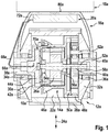
- the FIG. 1 shows a wheel device, in particular a Smartwheelvoriques.
- the wheel device comprises a wheel rim 10a.
- the wheel device includes a drive housing unit 12a.
- the wheel device comprises a drive unit 14a.
- the drive unit 14a is provided for an electric drive of the wheel rim 10a.
- the drive unit 14a is integrated in the drive housing unit 12a.
- the wheel device comprises a connection unit 16a for the detachable connection of the drive housing unit 12a to a vehicle 18a.
- the wheel device comprises a power supply unit 20a.
- the power supply unit 20a is provided for an electric power supply of the drive unit 14a.
- the power supply unit 20a is preferably captively connected to the drive housing unit 12a. However, it is also conceivable for the power supply unit 20a to be removable the drive housing unit 12a is arranged.
- the drive housing unit 12a forms a housing for the drive unit 14a.
- the drive housing unit 12a encloses an engine compartment 22a.
- the drive unit 14a is arranged inside the engine compartment 22a.
- the engine room 22a is hermetically sealed by the drive housing unit 12a.
- the drive unit 14a comprises an electric motor 26a.
- the electric motor 26a is formed by an electrically commutated DC motor. A power scaling takes place in particular via an axial motor length of the electric motor 26a and / or additional gear stages.
- the wheel device comprises a human-machine interface not shown here in detail.
- the man-machine interface starts directly upon initialization of the wheel device.
- the installed wheel device learns its position in an overall system, in particular with respect to other wheel devices. In this case, in particular a distance between at least two wheel devices to each other, as well as different parameter sets can be detected.
- the man-machine interface is provided for voice command detection and / or voice command processing.
- voice commands such as, in particular, "drive straight ahead”, “drive backwards”, “cornering right narrow”, “cornering left narrow”, “cornering right far”, “cornering left far”.
- parameters such as in particular travel distance, engine speed, speed, acceleration in the individual wheel devices can be detected.
- a position and / or a distance to other electrified wheel devices in the system can take place, in particular, by means of Bluetooth or other technologies that appear appropriate to the person skilled in the art.
- the wheel rim 10a forms a housing wall of the drive housing unit 12a.
- the wheel rim 10a defines the engine compartment 22a in a radial direction 24a.
- the wheel rim 10a is formed integrally with the housing wall.
- the wheel rim 10a is made of a metal.
- the wheel rim 10a forms a contact surface for a tread 28a.
- the tread 28a is formed here of a solid material. However, it is also conceivable in this connection that the tread 28a forms a pneumatic tire.
- the tread 28a is at least partially formed of a rubber material.
- the wheel rim 10a is provided with a special surface, so that a joining process can be applied in a form-fitting manner via a structured surface, non-positively via special surface treatments or coatings and / or materially bonded via defined material compositions, in particular for welding processes.
- the wheel rim 10a comprises a microstructuring.
- the tread 28a is connected to the wheel rim 10a by friction welding and / or laser welding. Alternatively and / or additionally, the tread 28a is shrunk onto the wheel rim 10a. Alternatively and / or additionally, the tread 28a is vulcanized onto the wheel rim 10a. It could also be provided a sleeve for vulcanizing / welding the tread 28a.
- the tread 28a is at least in an operating state firmly connected to the wheel rim 10a.
- the tread 28a is permanently rotatably connected to the wheel rim 10a, at least in one operating state.
- the wheel rim 10a is formed integrally with two Raddeckelwandungen 30a, 32a of the drive housing unit 12a.
- the Raddeckelwandungen 30a, 32a define the engine compartment 22a in an axial direction.
- the wheel rim 10a is materially connected to the two Raddeckelwandungen 30a, 32a, in particular welded.
- the wheel rim 10a can here be laser welded or friction welded to the two Raddeckelwandeptept 30a, 32a.
- the wheel rim 10a may alternatively or additionally be brazed, cold-soldered and / or glued to the two wheel cover walls 30a, 32a.
- the wheel rim 10a is positively connected to the two Raddeckelwandache 30a, 32a, in particular via at least one screw, at least one rivet, at least one bolt, at least one toothing.
- the wheel rim 10a is non-positively connected to the two Raddeckelwandungen 30a, 32a, in particular via a pressure.
- the power supply unit 20a is provided for storing electric power.
- the power supply unit 20a includes a lithium-based battery.
- the power supply unit 20a is captively connected to the drive unit 14a.
- the power supply unit 20a is electrically connected via a cable 68a to a circuit board 44a of an electronic unit 70a.
- the power supply unit 20a is fixedly connected to the connection unit 16a.
- the wheel device comprises wheel bearings 34a, 36a. Via the wheel bearings 34a, 36a, radial forces, in particular forces ⁇ 4.4 kN, are recorded. Axial forces, in particular forces ⁇ 60 N, are absorbed via the wheel bearings 34a, 36a.
- the wheel bearings 34a, 36a are fitted in the wheel cover walls 30a, 32a.
- the wheel bearings 34a, 36a are sealed against ingress of dirt and / or moisture.
- the wheel bearings 34a, 36a sit on Radachsbolzen 38a, 40a of the wheel device.
- the Radachsbolzen 38a, 40a are installed in the connection unit 16a. However, it is also conceivable in this connection that the wheel axle bolts 38a, 40a are mounted directly on the vehicle 18a (for example on a wheelbarrow).
- the Radachsbolzen 38 a is formed so that it secures all standing parts of the drive unit 14 a against rotation.
- the Radachsbolzen 38a forms a housing half of a board housing 42a.
- the board 44a is disposed near the Raddeckelwandung 30a.
- the heat can be dissipated via the Radachsbolzen 38a and on the other hand, the electrical energy from the power supply unit 20a of the drive unit 14a are supplied.
- the Radachsbolzen 38a and the board housing 42a are integrally formed with each other.
- the Radachsbolzen 38a and the board housing 42a are connected to a motor housing 46a of the electric motor 26a and a Geretehohlrad 48a of a gear unit 50a of the wheel device.
- the transmission unit 50a includes a planetary gear 86a. As a result, a torque can be transmitted to the rotatable wheel rim 10a from the drive unit 14a. Thus, a decoupling of an external load from the torque generated by the drive unit 14a is provided.
- a motor shaft 52a which can be driven by the electric motor 26a is mounted in three ways: for alignment of a rotor, it is mounted in two bearings 54a, 56a in the motor housing 46a.
- the motor shaft 52a forms a sun gear 60a of the gear unit 50a.
- the motor shaft 52a is supported by a floating bearing 58a in the hub axle 40a.
- the floating bearing 58a forms a needle bearing.
- the output of the torque via a planetary carrier 62a of the gear unit 50a takes place via the gear ring gear 48a of the gear unit 50a.
- the Geretehohlrad 48a is then directly connected to the wheel rim 10a and / or formed integrally with the wheel rim 10a.
- the wheel device includes a lifetime lubrication of the transmission unit 50a.
- the drive housing unit 12a is partially filled with oil.
- the oil lubricates the gears and the gear bearings. In addition, it can serve to better heat dissipation of the stator windings of the described electric motor 26a.
- the board housing 42a is sealed against the ingress of the oil.
- the motor housing 46a is sealed against the ingress of the oil. In the event that no lubricant is present, board and / or motor housing 42a, 46a sealed at least against a Gereteabrieb.
- the Radachsbolzen 38a, 40a are sealed against escaping oil.
- An open for installation cable gland 66a, in which a cable 68a extends between the board 44a and the power supply unit 20a is sealed after assembly, in particular poured.
- the connection unit 16a comprises a connection element 72a.
- the attachment member 72a partially encloses the drive housing unit 12a.
- the attachment element 72a is axially connected on both sides to the drive housing unit 12a.
- the connecting element 72a is connected to the Radachsbolzen 38a, 40a.
- the connection element 72a is partially plate-shaped.
- the attachment element 72a forms a bracket.
- the attachment element 72a has a flat contact surface 80a for contacting the vehicle 18a.
- the FIG. 2 shows a variant of in the FIG. 1 shown wheel device.
- the wheel device comprises a tire 74a '.
- the tire 74a ' forms a pneumatic tire.
- the tire 74a ' is disposed on the wheel rim 10a'.
- the wheel rim 10a ' forms a housing wall of the drive housing unit 12a'.
- the power supply unit 20a ' is integrated in the tire 74a'. It is also conceivable in this connection that the electronic unit 70a 'is integrated in the tire 74a'.
- the tire 74a ' includes an air chamber 76a'.
- the power supply unit 20a ' is disposed in the air chamber 76a'.
- the FIG. 3 shows another variant of the in the FIG. 1 shown wheel device.
- the connecting device 16a “comprises a connecting element 72a” .
- the connecting element 72a “partially encloses the drive housing unit 12a.”
- the connecting element 72a is axially connected on both sides to the drive housing unit 12a” Radachsbolzen 38a “connected.
- the connection element 72a” is partially formed plate-shaped.
- the attachment element 72a forms a stirrup
- the connecting element 72a has a flat contact surface 80a” for contacting the vehicle 18a ".
- the plate-shaped attachment element 72a has four attachment recesses 78a".
- the attachment recesses 78a are formed by bores 14.
- the attachment recesses 78a” serve to fix the wheel device to a vehicle (not shown here).
- the energy supply unit 20a is integrated in the connection unit 16a".
- the plate-shaped connection element 72a for this purpose comprises a closed receiving space in which the energy supply unit 20a" is arranged.
- the sensor unit 82a is partially integrated in the connection unit 16a.”
- the sensor unit 82a “comprises a bolt-shaped force sensor 90a” "is provided in particular for capturing a user power.
- the sensor unit 82a “comprises a torque sensor, a strain sensor or the like. It is conceivable that the sensor unit 82a” has at least one combination sensor which is provided to detect different characteristics, such as a force and a torque.
- the FIG. 4 shows another variant of the in the FIG. 1 shown wheel device.
- the connecting element 72a '' is formed plate-shaped in certain areas.
- the connecting element 72a ''' forms a bracket
- the connecting element 72a'' has a flat contact surface 80a''for contacting the vehicle 18a''.
- the connecting pin 92a'" is of cylindrical design.
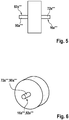
- the FIGS. 5 and 6 shows another variant of the in the FIG. 1 shown wheel device.
- the wheel device comprises a connection unit 16a "".
- the connection unit 16a “” comprises a connection element 72a “”.
- the connecting element 72a “” is designed as a wheel axle.
- the wheel device has a sensor unit 82a “”.
- the sensor unit 82a “” is integrated into the connection unit 16a "”.
- the sensor unit 82a “” comprises a force sensor 90a "”.
- the force sensor 90a "” is provided in particular for detecting a user force.
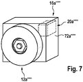
- the FIG. 7 shows another variant of the in the FIG. 1 shown wheel device.
- the wheel device comprises a connection unit 16a '"".
- the connection unit 16a '"" comprises a connection element 72a'"".
- the attachment element 72a ''' is arranged axially on one side of the drive housing unit 12a'''.
- the power supply unit 20a '"" is integrated in the connection unit 16a'"".
- the connecting element 72a '''for this purpose comprises a closed receiving space in which the power supply unit 20a''' is arranged.
- FIGS. 8 and 9 a further embodiment of the invention is shown.
- the following descriptions and the drawings are essentially limited to the differences between the embodiments, wherein with respect to the same designated components, in particular with respect to components with the same reference numerals, in principle to the drawings and / or the description of the other embodiment, in particular FIGS. 1 to 7 , can be referenced.
- To distinguish the embodiments of the letter a is the reference numerals of the embodiment in the FIGS. 1 to 7 readjusted.
- the letter a is replaced by the letter b.
- the FIG. 8 shows a wheel device, in particular a Smartwheelvoriques.
- the wheel device comprises a wheel rim 10b.
- the wheel device includes a drive housing unit 12b.
- the wheel device comprises a drive unit 14b.
- the drive unit 14b is for an electrical drive of the wheel rim 10b intended.
- the drive unit 14b is integrated in the drive housing unit 12b.
- the wheel device comprises a connection unit 16b for the detachable connection of the drive housing unit 12b to a vehicle 18b.
- the wheel device includes a power supply unit 20b.
- the power supply unit 20b is provided for an electric power supply of the drive unit 14b.
- the power supply unit 20b is captively connected to the drive housing unit 12b.
- the drive housing unit 12b forms a housing for the drive unit 14b.
- the drive housing unit 12b encloses an engine compartment 22b.
- the drive unit 14b is disposed inside the engine compartment 22b.
- the engine compartment 22b is hermetically sealed by the drive housing unit 12b.
- the drive unit 14b includes an electric motor 26b.
- the electric motor 26b is formed by an electrically commutated DC motor. A power scaling takes place in particular via an axial motor length of the electric motor 26b and / or additional gear stages.
- the electric motor 26b is offset radially relative to a rotational axis 84b of the wheel rim 10b.
- the wheel device comprises a gear unit 50b.
- the transmission unit 50b includes a planetary gear 86b.
- the electric motor 26b is arranged axially offset from the planetary gear 86b.
- the transmission unit 50b comprises a primary gear 64b.
- the primary gear 64b is disposed axially between the electric motor 26b and the planetary gear 86b.
- the primary gear 64b and the planetary gear 86b are disposed in common within the engine compartment 22b of the drive housing unit 12b.
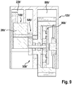
- the wheel device on a gear unit 50b ' which is provided for a torque transmission between the drive unit 14b' and the wheel rim 10b '.
- the gear unit 50b ' is partially disposed outside an engine room 22b' of the drive housing unit 12b '. More specifically, the electric motor 26b 'and a primary gear 64b' of the gear unit 50b 'are inside the engine compartment 22b 'arranged.
- a planetary gear 86b 'of the gear unit 50b' is disposed outside the engine room 22b 'within a gear room 88b'.
Landscapes
- Engineering & Computer Science (AREA)
- Chemical & Material Sciences (AREA)
- Combustion & Propulsion (AREA)
- Transportation (AREA)
- Mechanical Engineering (AREA)
- Arrangement Or Mounting Of Propulsion Units For Vehicles (AREA)
- Measuring Fluid Pressure (AREA)
Abstract
Description
- Es ist bereits eine Radvorrichtung, insbesondere Smartwheelvorrichtung, mit zumindest einer Radfelge, mit einer Antriebsgehäuseeinheit, mit einer Antriebseinheit, die zu einem elektrischen Antrieb der zumindest einen Radfelge vorgesehen ist, vorgeschlagen worden.
- Es wird eine Radvorrichtung vorgeschlagen, insbesondere eine Smartwheelvorrichtung, mit zumindest einer Radfelge, mit einer Antriebsgehäuseeinheit, mit einer Antriebseinheit, die zu einem elektrischen Antrieb der zumindest einen Radfelge vorgesehen ist, wobei die Antriebseinheit zumindest im Wesentlichen in die Antriebsgehäuseeinheit integriert ist, mit einer Anbindungseinheit zur lösbaren Anbindung der Antriebsgehäuseeinheit an einem Fahrzeug und mit einer Energieversorgungseinheit, die zu einer elektrischen Energieversorgung der Antriebseinheit vorgesehen und, insbesondere unverlierbar, mit der Antriebsgehäuseeinheit verbunden ist. Dadurch kann die Radvorrichtung besonders flexibel an unterschiedlichen Fahrzeugen angeordnet und/oder ausgetauscht werden. Ein Ersetzen einer konventionellen Radvorrichtung durch die erfindungsgemäße Radvorrichtung kann vorteilhaft besonders schnell und zuverlässig erfolgen. Unter einer "Radfelge" soll in diesem Zusammenhang insbesondere ein Teil der Radvorrichtung verstanden werden, das eine Kontaktfläche für einen Laufbelag und/oder für einen Reifen, insbesondere für einen Luftreifen, bildet und/oder den Laufbelag und/oder den Reifen trägt. Insbesondere sind ein Laufbelag und/oder ein Reifen fest und/oder permanent drehfest mit der Radfelge verbindbar.
- Besonders vorteilhaft ist die zumindest eine Radfelge aus einem Kunststoff und/oder aus einem Metall ausgebildet. Die Antriebsgehäuseeinheit bildet vorzugsweise ein Gehäuse für zumindest die Antriebseinheit aus. Vorzugsweise umschließt die Antriebsgehäuseeinheit einen Motorraum, in dem die Antriebseinheit zumindest im Wesentlichen angeordnet ist. Besonders vorteilhaft ist der Motorraum von einer Umgebung durch die Antriebsgehäuseeinheit hermetisch getrennt und/oder abgedichtet. Die Antriebseinheit umfasst vorzugsweise zumindest einen Elektromotor. Der Elektromotor ist bevorzugt von einem Gleichstrommotor, von einem elektrisch kommutierten Gleichstrommotor oder einem Drehstrommotor gebildet. Unter "integriert" soll in diesem Zusammenhang insbesondere aufgenommen, umschlossen und/oder eingeschlossen verstanden werden. Bevorzugt umfasst die Radvorrichtung genau eine Radfelge. Vorzugsweise ist zumindest ein Bauteil und/oder eine Einheit der Antriebseinheit in die Antriebsgehäuseeinheit integriert.
- Die Energieversorgungseinheit ist vorzugsweise zur Speicherung elektrischer Energie vorgesehen. Insbesondere ist die Energieversorgungseinheit zur statischen Speicherung elektrischer Energie durch Ladungstrennung und/oder bevorzugt durch elektrochemische Speicherung elektrischer Energie vorgesehen. Vorteilhaft umfasst die zumindest eine Energieversorgungseinheit zumindest einen Kondensator, einen Superkondensator, einen Bleiakkumulator, einen Lithium-Cobaltdioxid-Akkumulator, einen Lithium-Mangan-Akkumulator, einen Lithium-Polymer-Akkumulator, einen Lithium-Eisen-Phosphat-Akkumulator, einen Lithium-Eisen-Yttrium-Phosphat-Akkumulator, einen Lithium-Luft-Akkumulator, einen Lithium-Titanat-Akkumulator, einen Lithium-Schwefel-Akkumulator, einen Natrium-Nickelchlorid-Akkumulator, einen Natrium-Schwefel-Akkumulator, einen Nickel-Eisen-Akkumulator, einen Nickel-Cadmium-Akkumulator, einen Nickel-Metallhydrid-Akkumulator, einen Nickel-Wasserstoff-Akkumulator, einen Nickel-Zink-Akkumulator, einen Silber-Zink-Akkumulator, einen Zinn-Schwefel-Lithium-Akkumulator, eine Brennstoffzelle und/oder eine Batterie.
- Unter "unverlierbar" soll hier insbesondere eine Verbindung von zumindest zwei Elementen verstanden werden, die nicht zerstörungsfrei voneinander trennbar und/oder lediglich unter der Zuhilfenahme von Werkzeugen, wie beispielsweise einem Schraubendreher, einem Gabelschlüssel, einem Außensechskant (Inbusschlüssel), einem Torxschlüssel, einer Säge, insbesondere einer mechanischen Säge usw., und/oder chemischen Trennmitteln, wie beispielsweise Lösungsmitteln usw., voneinander trennbar sind. Die Energieversorgungseinheit kann alternativ auch trennbar mit der Antriebsgehäuseeinheit ausgebildet sein. Insbesondere ist die Radvorrichtung zu einem Ersetzen einer nichtangetriebenen Radvorrichtung eines Fahrzeugs, insbesondere bei einem Umrüsten des Fahrzeugs, vorgesehen. Unter "vorgesehen" soll insbesondere speziell programmiert, ausgelegt und/oder ausgestattet verstanden werden. Darunter, dass ein Objekt zu einer bestimmten Funktion vorgesehen ist, soll insbesondere verstanden werden, dass das Objekt diese bestimmte Funktion in zumindest einem Anwendungs- und/oder Betriebszustand erfüllt und/oder ausführt.
- In einer weiteren Ausgestaltung der Erfindung wird vorgeschlagen, dass die zumindest eine Radfelge zumindest eine Gehäusewandung der Antriebsgehäuseeinheit ausbildet. Dadurch kann die Radvorrichtung besonders kompakt und gewichtsarm ausgebildet werden. Insbesondere begrenzt die zumindest eine Radfelge den Motorraum in eine Radialrichtung. Die zumindest eine Radfelge ist bevorzugt einteilig und/oder einstückig mit der Gehäusewandung ausgebildet. Zusätzlich wird vorgeschlagen, dass die Radvorrichtung eine Getriebeeinheit umfasst, die zu einer Drehmomentübertragung zwischen der Antriebseinheit und der zumindest einen Radfelge vorgesehen ist, wobei die Radfelge ein Hohlrad der Getriebeeinheit ausbildet. Dadurch kann die Radvorrichtung besonders kompakt und betriebssicher ausgebildet werden. Bevorzugt umfasst die Getriebeeinheit zumindest einen Planetenradsatz.
- Ferner wird vorgeschlagen, dass die Anbindungseinheit zumindest ein Anbindungselement umfasst, welches die Antriebsgehäuseeinheit zumindest teilweise umschließt. Dadurch kann eine besonders stabile Anbindung der Radvorrichtung an ein Fahrzeug erzielt werden. Bevorzugt ist das zumindest eine Anbindungselement axial beidseitig mit der Antriebsgehäuseeinheit verbunden. Die Begriffe "axial", "radial", "Axialrichtung" bzw. "Radialrichtung" sollen sich in diesem Zusammenhang insbesondere auf eine Hauptrotationsachse der Radfelge in einem Betrieb beziehen.
- Zudem wird vorgeschlagen, dass die Anbindungseinheit zumindest ein plattenförmiges Anbindungselement und/oder zumindest einen Verbindungszapfen umfasst. Dadurch können zumindest in einem Betrieb besonders hohe Betriebskräfte zwischen der Radvorrichtung und dem Fahrzeug übertragen werden. Bevorzugt weist das plattenförmige Anbindungselement eine zumindest im Wesentlichen ebene Kontaktfläche zur Kontaktierung mit dem Fahrzeug auf. Weiterhin vorteilhaft ist das plattenförmige Anbindungselement rechteckig oder rund ausgebildet. Weiterhin vorteilhaft umfasst das plattenförmige Anbindungselement Befestigungsausnehmungen, insbesondere Bohrungen, zur Befestigung am Fahrzeug auf. Besonders vorteilhaft weist der zumindest eine Verbindungszapfen einen runden Querschnitt auf.
- Des Weiteren wird vorgeschlagen, dass die Energieversorgungseinheit zumindest im Wesentlichen in die Anbindungseinheit integriert ist. Dadurch kann die Energieversorgungseinheit vorteilhaft besonders groß ausgebildet werden. Weiterhin kann eine Abwärme der Energieversorgungseinheit besonders einfach abgeführt werden. Bevorzugt umfasst die Anbindungseinheit eine Elektronikeinheit zur Steuerung und/oder Regelung der Antriebseinheit und/oder zur Überwachung der Energieversorgungseinheit.
- Weiterhin wird vorgeschlagen, dass die Radvorrichtung zumindest einen auf der Radfelge angeordneten Reifen, insbesondere Luftreifen, umfasst, wobei die Energieversorgungseinheit zumindest im Wesentlichen in den Reifen integriert ist. Dadurch kann die Radvorrichtung besonders kompakt ausgebildet werden. Weiterhin vorteilhaft ist die Elektronikeinheit zumindest im Wesentlichen in den Reifen integriert ist. Bevorzugt sind die Radfelge und der Reifen stoffschlüssig miteinander verbunden. Weiterhin vorteilhaft sind die Radfelge und der Reifen formschlüssig und/oder kraftschlüssig miteinander verbunden.
- Ferner wird vorgeschlagen, dass die Radvorrichtung eine Getriebeeinheit aufweist, die zu einer Drehmomentübertragung zwischen der Antriebseinheit und der zumindest einen Radfelge vorgesehen ist, wobei die Getriebeeinheit zumindest im Wesentlichen außerhalb eines Motorraums der Antriebsgehäuseeinheit angeordnet ist. Dadurch können vorteilhaft besonders große Betriebskräfte auf die Radfelge übertragen werden.
- Zudem wird vorgeschlagen, dass die Radvorrichtung eine Sensoreinheit aufweist, die zumindest teilweise in die Anbindungseinheit integriert ist. Dadurch können Kenngrößen besonders zuverlässig erfasst werden. Weiterhin kann die Radvorrichtung besonders kompakt ausgebildet werden. Unter einer "Sensoreinheit" soll in diesem Zusammenhang insbesondere eine Einheit verstanden werden, die dazu vorgesehen ist, zumindest eine Kenngröße, insbesondere eine Schnittstellenkenngröße der Anbindungseinheit, wie beispielsweise eine an der Anbindungseinheit wirkende Kraft und/oder ein an der Anbindungseinheit wirkendes Drehmoment, eine Umgebungskenngröße und/oder eine Betriebskenngröße der Radvorrichtung zu erfassen.
- Weiterhin wird vorgeschlagen, dass die zumindest eine Radfelge einstückig mit zumindest einer Raddeckelwandung der Antriebsgehäuseeinheit ausgebildet ist. Dadurch kann die Radvorrichtung besonders kompakt und belastbar ausgebildet werden. Insbesondere begrenzt die zumindest eine Raddeckelwandung den Motorraums in eine Axialrichtung.
- Eine besonders vorteilhafte Anwendung findet die erfindungsgemäße Radvorrichtung an einem Fahrzeug. Das Fahrzeug kann insbesondere einen Rollstuhl, ein Kickelec, ein Kickboard, einen Koffer, eine Babylaufhilfe, einen Rollator, einen Einkaufstrolley, eine Patientengehhilfe, einen Golftrolley, einen Restaurantstrolley, einen Kantinentrolley, einen Logistiktrolley, einen Postwagen, einen Gartentrolley, einen Pflanzkübel, einen Werkzeugwagen, einen Materialwagen, einen Baustellentrolley, eine Schubkarre, eine Mülltonne, ein Kinderspielzeug, ein Einfahrtstor, ein leichtes Elektrofahrzeug (LSEV), ein Dreirad, ein Elektroscooter, ein Elektromotorrad (>2 kW), einen Gabelstabler, einen Staubsaugerroboter, einen Rasenmäherroboter, einen Logistikroboter, einen Schwimmbadreinigungsroboter, einen Agrarroboter, einen Viehzuchtroboter, einen Minensuchroboter, einen Minenzerstörungsroboter, einen Bodenreinigungsroboter, einen Tankreinigungsroboter, einen Rohrreinigungsroboter, einen Inspektionssystemroboter, einen Wartungsroboter, einen Bau- und Abrissroboter, einen Rettungs- und Sicherheitsroboter, eine mobile Roboterplattform, einen Führungs- und Informationsroboter, eine Schneeräumfahrzeug, ein Schneemobil, ein All Terrain Vehicle (Quad), ein Utility Terrain Vehicle, ein Krankenbett, einen Bollerwagen, einen Kindergartenwagen, einen Schulranzen, einen Einkaufswagen, einen Sackkarren und/oder einen Wäschewagen ausbilden.
- Die erfindungsgemäße Radvorrichtung soll hierbei nicht auf die oben beschriebene Anwendung und Ausführungsform beschränkt sein. Insbesondere kann die erfindungsgemäße Radvorrichtung zu einer Erfüllung einer hierin beschriebenen Funktionsweise eine von einer hierin genannten Anzahl von einzelnen Elementen, Bauteilen und Einheiten abweichende Anzahl aufweisen.
- Weitere Vorteile ergeben sich aus der folgenden Zeichnungsbeschreibung. In der Zeichnung sind neun Ausführungsbeispiele der Erfindung dargestellt. Die Zeichnung, die Beschreibung und die Ansprüche enthalten zahlreiche Merkmale in Kombination. Der Fachmann wird die Merkmale zweckmäßigerweise auch einzeln betrachten und zu sinnvollen weiteren Kombinationen zusammenfassen.
- Es zeigen:
- Fig. 1
- eine erfindungsgemäße Radvorrichtung in einer schematischen Schnittdarstellung,
- Fig. 2
- eine Variante der Radvorrichtung nach
Figur 1 in einer schematischen Schnittdarstellung, - Fig. 3
- eine weitere Variante der Radvorrichtung nach
Figur 1 in einer schematischen, perspektivischen Darstellung, - Fig. 4
- eine weitere Variante der Radvorrichtung nach
Figur 1 in einer schematischen, perspektivischen Darstellung, - Fig. 5
- eine weitere Variante der Radvorrichtung nach
Figur 1 in einer Vorderansicht, - Fig. 6
- die Variante der Radvorrichtung nach
Figur 5 in einer schematischen, perspektivischen Darstellung, - Fig. 7
- eine weitere Variante der Radvorrichtung nach
Figur 1 in einer schematischen, perspektivischen Darstellung, - Fig. 8
- ein weiteres Ausführungsbeispiel einer Radvorrichtung in einer schematischen Schnittdarstellung und
- Fig. 9
- eine Variante der Radvorrichtung nach
Figur 8 in einer schematischen Schnittdarstellung. - Die
Figur 1 zeigt eine Radvorrichtung, insbesondere eine Smartwheelvorrichtung. Die Radvorrichtung umfasst eine Radfelge 10a. Die Radvorrichtung umfasst eine Antriebsgehäuseeinheit 12a. Die Radvorrichtung umfasst eine Antriebseinheit 14a. Die Antriebseinheit 14a ist zu einem elektrischen Antrieb der Radfelge 10a vorgesehen. Die Antriebseinheit 14a ist in die Antriebsgehäuseeinheit 12a integriert. Die Radvorrichtung umfasst eine Anbindungseinheit 16a zur lösbaren Anbindung der Antriebsgehäuseeinheit 12a an einem Fahrzeug 18a. Die Radvorrichtung umfasst eine Energieversorgungseinheit 20a. - Die Energieversorgungseinheit 20a ist zu einer elektrischen Energieversorgung der Antriebseinheit 14a vorgesehen. Die Energieversorgungseinheit 20a ist vorzugsweise unverlierbar mit der Antriebsgehäuseeinheit 12a verbunden. Es ist jedoch auch denkbar, dass die Energieversorgungseinheit 20a abnehmbar an der Antriebsgehäuseeinheit 12a angeordnet ist. Die Antriebsgehäuseeinheit 12a bildet ein Gehäuse für die Antriebseinheit 14a aus. Die Antriebsgehäuseeinheit 12a umschließt einen Motorraum 22a. Die Antriebseinheit 14a ist innerhalb des Motorraums 22a angeordnet. Der Motorraum 22a ist durch die Antriebsgehäuseeinheit 12a hermetisch abgedichtet. Die Antriebseinheit 14a umfasst einen Elektromotor 26a. Der Elektromotor 26a ist von einem elektrisch kommutierten Gleichstrommotor gebildet. Eine Leistungsskalierung erfolgt insbesondere über eine axiale Motorlänge des Elektromotors 26a und/oder zusätzliche Getriebestufen.
- Die Radvorrichtung umfasst eine hier nicht näher gezeigte Mensch-Maschine-Schnittstelle. Die Mensch-Maschine-Schnittstelle startet direkt bei einem Initialisieren der Radvorrichtung. Bei einer Inbetriebnahme erlernt die verbaute Radvorrichtung ihre Position in einem Gesamtsystem, insbesondere in Bezug auf weitere Radvorrichtungen. Hierbei kann insbesondere ein Abstand zwischen zumindest zwei Radvorrichtungen zueinander, sowie verschiedene Parametersätze erfasst werden.
- Die Mensch-Maschine-Schnittstelle ist zu einer Sprachbefehlerfassung und/oder Sprachbefehlverarbeitung vorgesehen. Beispielsweise ist es denkbar, die Radvorrichtung mittels Sprachbefehlen wie insbesondere "Fahrt geradeaus", "Fahrt rückwärts", "Kurvenfahrt rechts eng", "Kurvenfahrt links eng", "Kurvenfahrt rechts weit", "Kurvenfahrt links weit" zu steuern. Hierbei können Parameter wie insbesondere Fahrstrecke, Motordrehzahl, Geschwindigkeit, Beschleunigung in den einzelnen Radvorrichtungen erfasst werden. Eine Position und/oder ein Abstand zu anderen elektrifizierten Radvorrichtungen im System kann insbesondere mittels Bluetooth oder anderen dem Fachmann als sinnvoll erscheinenden Technologien erfolgen.
- Die Radfelge 10a bildet eine Gehäusewandung der Antriebsgehäuseeinheit 12a aus. Die Radfelge 10a begrenzt den Motorraum 22a in eine Radialrichtung 24a. Die Radfelge 10a ist einstückig mit der Gehäusewandung ausgebildet. Die Radfelge 10a ist aus einem Metall hergestellt. Die Radfelge 10a bildet eine Kontaktfläche für einen Laufbelag 28a aus. Der Laufbelag 28a ist hierbei aus einem Vollmaterial ausgebildet. Es ist in diesem Zusammenhang jedoch auch denkbar, dass der Laufbelag 28a einen Luftreifen ausbildet. Der Laufbelag 28a ist zumindest teilweise aus einem Gummimaterial ausgebildet. Die Radfelge 10a ist mit einer speziellen Oberfläche ausgestattet, sodass ein Fügeverfahren formschlüssig über eine strukturierte Oberfläche, kraftschlüssig über spezielle Oberflächenbehandlungen bzw. Beschichtungen und/oder stoffschlüssig über definierte Werkstoffzusammensetzungen insbesondere für Schweißverfahren angewendet werden können. Insbesondere umfasst die Radfelge 10a eine Mikrostrukturierung.
- Im Folgenden werden beispielhaft mögliche Verbindungsmöglichkeiten zwischen der Radfelge 10a und dem Laufbelag 28a beschrieben. Der Laufbelag 28a ist über Reibschweißen und/oder Laserschweißen mit der Radfelge 10a verbunden. Alternativ und/oder zusätzlich ist der Laufbelag 28a auf die Radfelge 10a aufgeschrumpft. Alternativ und/oder zusätzlich ist der Laufbelag 28a auf die Radfelge 10a aufvulkanisiert. Es könnte ferner eine Hülse zum Aufvulkanisieren/Aufschweißen des Laufbelags 28a vorgesehen sein. Der Laufbelag 28a ist zumindest in einem Betriebszustand fest mit der Radfelge 10a verbunden. Der Laufbelag 28a ist zumindest in einem Betriebszustand permanent drehfest mit der Radfelge 10a verbunden.
- Die Radfelge 10a ist einstückig mit zwei Raddeckelwandungen 30a, 32a der Antriebsgehäuseeinheit 12a ausgebildet. Die Raddeckelwandungen 30a, 32a begrenzen den Motorraum 22a in eine Axialrichtung. Die Radfelge 10a ist mit den zwei Raddeckelwandungen 30a, 32a stoffschlüssig verbunden, insbesondere verschweißt. Die Radfelge 10a kann hierbei mit den zwei Raddeckelwandungen 30a, 32a laserverschweißt oder reibverschweißt werden. Die Radfelge 10a kann alternativ oder zusätzlich mit den zwei Raddeckelwandungen 30a, 32a verlötet, kaltverlötet und/oder verklebt sein. Es ist in diesem Zusammenhang jedoch auch denkbar, dass die Radfelge 10a mit den zwei Raddeckelwandungen 30a, 32a formschlüssig verbunden ist, insbesondere über zumindest eine Schraube, zumindest eine Niete, zumindest einen Bolzen, zumindest eine Verzahnung. Weiterhin ist es denkbar, dass die Radfelge 10a mit den zwei Raddeckelwandungen 30a, 32a kraftschlüssig verbunden ist, insbesondere über eine Pressung.
- Die Energieversorgungseinheit 20a ist zur Speicherung elektrischer Energie vorgesehen. Die Energieversorgungseinheit 20a umfasst einen lithiumbasierten Akkumulator. Die Energieversorgungseinheit 20a ist unverlierbar mit der Antriebseinheit 14a verbunden. Die Energieversorgungseinheit 20a ist über ein Kabel 68a mit einer Platine 44a einer Elektronikeinheit 70a elektrisch verbunden. Die Energieversorgungseinheit 20a ist fest mit der Anbindungseinheit 16a verbunden.
- Die Radvorrichtung umfasst Radlager 34a, 36a.Über die Radlager 34a, 36a werden radiale Kräfte, insbesondere Kräfte < 4,4 kN, aufgenommen. Über die Radlager 34a, 36a werden axiale Kräfte, insbesondere Kräfte < 60 N, aufgenommen. Die Radlager 34a, 36a sind in den Raddeckelwandungen 30a, 32a eingepasst. Die Radlager 34a, 36a sind gegen ein Eindringen von Schmutz und/oder Feuchtigkeit abgedichtet. Die Radlager 34a, 36a sitzen auf Radachsbolzen 38a, 40a der Radvorrichtung. Die Radachsbolzen 38a, 40a sind in die Anbindungseinheit 16a eingebaut. Es ist in diesem Zusammenhang jedoch auch denkbar, dass die Radachsbolzen 38a, 40a direkt am Fahrzeug 18a montiert werden (z.B. bei einer Schubkarre).
- Einer der Radachsbolzen 38a ist so geformt, dass er alle stehenden Teile der Antriebseinheit 14a gegen Verdrehung sichert. Der Radachsbolzen 38a bildet eine Gehäusehälfte eines Platinengehäuses 42a aus. Die Platine 44a ist nahe der Raddeckelwandung 30a angeordnet. Hierbei können einerseits die Wärme über den Radachsbolzen 38a abgeführt werden und andererseits die elektrische Energie aus der Energieversorgungseinheit 20a der Antriebseinheit 14a zugeführt werden. Der Radachsbolzen 38a und das Platinengehäuse 42a sind einstückig miteinander ausgebildet. Der Radachsbolzen 38a und das Platinengehäuse 42a sind mit einem Motorgehäuse 46a des Elektromotors 26a und einem Getriebehohlrad 48a einer Getriebeeinheit 50a der Radvorrichtung verbunden.
- Die Getriebeeinheit 50a umfasst ein Planetengetriebe 86a. Dadurch kann aus der Antriebseinheit 14a ein Drehmoment auf die drehbare Radfelge 10a übertragen werden. Somit ist eine Entkopplung einer äußeren Last vom durch die Antriebseinheit 14a erzeugten Drehmoment vorgesehen. Eine vom Elektromotor 26a antreibbare Motorwelle 52a ist dreifach gelagert: Für eine Ausrichtung eines Rotors ist sie in zwei Lagern 54a, 56a im Motorgehäuse 46a gelagert. Die Motorwelle 52a bildet ein Sonnenrad 60a der Getriebeeinheit 50a aus. Für eine genaue Ausrichtung des Sonnenrads 60a in der Getriebeeinheit 50a ist die Motorwelle 52a über ein Loslager 58a im Radachsbolzen 40a gelagert. Das Loslager 58a bildet ein Nadellager aus.
- Der Abtrieb des Drehmoments erfolgt über einen Planetenträger 62a der Getriebeeinheit 50a. Es ist aber auch vorstellbar, dass der Abtrieb über das Getriebehohlrad 48a der Getriebeeinheit 50a erfolgt. Das Getriebehohlrad 48a ist dann mit der Radfelge 10a direkt verbunden und/oder einstückig mit der Radfelge 10a ausgebildet. Alternativ kann das Getriebehohlrad 48a mit zumindest einer der Raddeckelwandungen 30a, 32a direkt verbunden und/oder einstückig mit zumindest einer der Raddeckelwandungen 30a, 32a ausgebildet sein.
- Im Antriebssystem kann dann eine Erhöhung der Leistung und/oder des Drehmoments durch eine axiale Verlängerung der aktiven Motorteile oder durch eine Ergänzung um weitere Getriebestufen erfolgen. Die Radvorrichtung umfasst eine Lebensdauerschmierung der Getriebeeinheit 50a. Für Anwendungen, in denen hohe Laufzeiten auftreten, wird die Antriebsgehäuseeinheit 12a teilweise mit Öl befüllt. Das Öl dient zur Schmierung der Zahnräder sowie der Zahnradlagerungen. Außerdem kann es zur besseren Entwärmung der Statorwicklungen des beschriebenen Elektromotors 26a dienen.
- Für Anwendungen mit niedrigeren Lebensdauern kann für die Getriebeschmierung auch eine Fettschmierung vorgesehen werden oder die Schmierung kann ganz entfallen. Das Platinengehäuse 42a ist gegen das Eindringen des Öls abgedichtet. Das Motorgehäuse 46a ist gegen das Eindringen des Öls abgedichtet. Für den Fall, dass kein Schmierstoff vorhanden ist, sind Platinen- und/oder Motorgehäuse 42a, 46a zumindest gegen einen Getriebeabrieb abgedichtet. Die Radachsbolzen 38a, 40a sind gegen ausdringendes Öl abgedichtet. Eine für eine Montage offene Kabeldurchführung 66a, in welche ein Kabel 68a zwischen der Platine 44a und der Energieversorgungseinheit 20a verläuft, wird nach der Montage abgedichtet, insbesondere ausgegossen.
- Die Anbindungseinheit 16a umfasst ein Anbindungselement 72a. Das Anbindungselement 72a umschließt die Antriebsgehäuseeinheit 12a teilweise. Das Anbindungselement 72a ist axial beidseitig mit der Antriebsgehäuseeinheit 12a verbunden. Das Anbindungselement 72a ist mit den Radachsbolzen 38a, 40a verbunden. Das Anbindungselement 72a ist bereichsweise plattenförmig ausgebildet. Das Anbindungselement 72a bildet einen Bügel aus. Das Anbindungselement 72a weist eine ebene Kontaktfläche 80a zur Kontaktierung mit dem Fahrzeug 18a auf.
- Die
Figur 2 zeigt eine Variante der in derFigur 1 gezeigten Radvorrichtung. Im Unterschied zurFigur 1 umfasst die Radvorrichtung einen Reifen 74a'. Der Reifen 74a' bildet einen Luftreifen aus. Der Reifen 74a' ist auf der Radfelge 10a' angeordnet. Die Radfelge 10a' bildet eine Gehäusewandung der Antriebsgehäuseeinheit 12a' aus. Die Energieversorgungseinheit 20a' ist in den Reifen 74a' integriert. Es ist in diesem Zusammenhang auch denkbar, dass die Elektronikeinheit 70a' in den Reifen 74a' integriert ist. Der Reifen 74a' umfasst eine Luftkammer 76a'. Die Energieversorgungseinheit 20a' ist in der Luftkammer 76a' angeordnet. - Die
Figur 3 zeigt eine weitere Variante der in derFigur 1 gezeigten Radvorrichtung. Die Radvorrichtung umfasst eine Anbindungseinheit 16a". Die Anbindungseinheit 16a" umfasst ein Anbindungselement 72a". Das Anbindungselement 72a" umschließt die Antriebsgehäuseeinheit 12a" teilweise. Das Anbindungselement 72a" ist axial beidseitig mit der Antriebsgehäuseeinheit 12a" verbunden. Das Anbindungselement 72a" ist mit den Radachsbolzen 38a" verbunden. Das Anbindungselement 72a" ist bereichsweise plattenförmig ausgebildet. Das Anbindungselement 72a" bildet einen Bügel aus. Das Anbindungselement 72a" bildet einen Flansch aus. Das Anbindungselement 72a" weist eine ebene Kontaktfläche 80a" zur Kontaktierung mit dem Fahrzeug 18a" auf. Das plattenförmige Anbindungselement 72a" weist vier Befestigungsausnehmungen 78a" auf. Die Befestigungsausnehmungen 78a" sind von Bohrungen gebildet. Die Befestigungsausnehmungen 78a" dienen zu einer Befestigung der Radvorrichtung an einem Fahrzeug (hier nicht gezeigt). - Die Energieversorgungseinheit 20a" ist in die Anbindungseinheit 16a" integriert. Das plattenförmige Anbindungselement 72a" umfasst hierzu einen geschlossenen Aufnahmeraum in dem die Energieversorgungseinheit 20a" angeordnet ist. Ferner weist die Radvorrichtung eine Sensoreinheit 82a" auf. Die Sensoreinheit 82a" ist teilweise in die Anbindungseinheit 16a" integriert. Die Sensoreinheit 82a" umfasst einen bolzenförmigen Kraftsensor 90a". Der Kraftsensor 90a" ist in einer der Befestigungsausnehmungen 78a" angeordnet. Der Kraftsensor 90a" ist insbesondere zu einer Erfassung einer Nutzerkraft vorgesehen. Alternativ oder zusätzlich umfasst die Sensoreinheit 82a" einen Drehmomentsensor, einen Dehnungssensor o. dgl. Es ist denkbar, dass die Sensoreinheit 82a" zumindest einen Kombinationssensor aufweist, der dazu vorgesehen ist, verschiedene Kenngrößen, wie beispielsweise eine Kraft und ein Drehmoment, zu erfassen.
- Die
Figur 4 zeigt eine weitere Variante der in derFigur 1 gezeigten Radvorrichtung. Die Radvorrichtung umfasst eine Anbindungseinheit 16a'". Die Anbindungseinheit 16a'" umfasst ein Anbindungselement 72a'". Das Anbindungselement 72a'" umschließt die Antriebsgehäuseeinheit 12a'" teilweise. Das Anbindungselement 72a'" ist axial beidseitig mit der Antriebsgehäuseeinheit 12a'" verbunden. Das Anbindungselement 72a'" ist mit den Radachsbolzen 38a'" verbunden. Das Anbindungselement 72a'" ist bereichsweise plattenförmig ausgebildet. Das Anbindungselement 72a'" bildet einen Bügel aus. Das Anbindungselement 72a'" weist eine ebene Kontaktfläche 80a'" zur Kontaktierung mit dem Fahrzeug 18a'" auf. Die Anbindungseinheit 16a'" umfasst einen Verbindungszapfen 92a"'. Der Verbindungszapfen 92a'" ist insbesondere zu einer Befestigung an einem Rohrende vorgesehen. Der Verbindungszapfen 92a'" ist zylinderförmig ausgebildet. - Die
Figuren 5 und 6 zeigt eine weitere Variante der in derFigur 1 gezeigten Radvorrichtung. Die Radvorrichtung umfasst eine Anbindungseinheit 16a"". Die Anbindungseinheit 16a"" umfasst ein Anbindungselement 72a"". Das Anbindungselement 72a"" ist als Radachse ausgebildet. Ferner weist die Radvorrichtung eine Sensoreinheit 82a"" auf. Die Sensoreinheit 82a"" ist in die Anbindungseinheit 16a"" integriert. Die Sensoreinheit 82a"" umfasst einen Kraftsensor 90a"". Der Kraftsensor 90a"" ist insbesondere zu einer Erfassung einer Nutzerkraft vorgesehen. - Die
Figur 7 zeigt eine weitere Variante der in derFigur 1 gezeigten Radvorrichtung. Die Radvorrichtung umfasst eine Anbindungseinheit 16a'"". Die Anbindungseinheit 16a'"" umfasst ein Anbindungselement 72a'"". Das Anbindungselement 72a'"" ist axial einseitig der Antriebsgehäuseeinheit 12a'"" angeordnet. Die Energieversorgungseinheit 20a'"" ist in die Anbindungseinheit 16a'"" integriert. Das Anbindungselement 72a'"" umfasst hierzu einen geschlossenen Aufnahmeraum in dem die Energieversorgungseinheit 20a'"" angeordnet ist. - In den
Figuren 8 und9 ist ein weiteres Ausführungsbeispiel der Erfindung gezeigt. Die nachfolgenden Beschreibungen und die Zeichnungen beschränken sich im Wesentlichen auf die Unterschiede zwischen den Ausführungsbeispielen, wobei bezüglich gleich bezeichneter Bauteile, insbesondere in Bezug auf Bauteile mit gleichen Bezugszeichen, grundsätzlich auch auf die Zeichnungen und/oder die Beschreibung des anderen Ausführungsbeispiels, insbesondere derFiguren 1 bis 7 , verwiesen werden kann. Zur Unterscheidung der Ausführungsbeispiele ist der Buchstabe a den Bezugszeichen des Ausführungsbeispiels in denFiguren 1 bis 7 nachgestellt. Im Ausführungsbeispiel derFiguren 8 und9 ist der Buchstabe a durch den Buchstaben b ersetzt. - Die
Figur 8 zeigt eine Radvorrichtung, insbesondere eine Smartwheelvorrichtung. Die Radvorrichtung umfasst eine Radfelge 10b. Die Radvorrichtung umfasst eine Antriebsgehäuseeinheit 12b. Die Radvorrichtung umfasst eine Antriebseinheit 14b. Die Antriebseinheit 14b ist zu einem elektrischen Antrieb der Radfelge 10b vorgesehen. Die Antriebseinheit 14b ist in die Antriebsgehäuseeinheit 12b integriert. Die Radvorrichtung umfasst eine Anbindungseinheit 16b zur lösbaren Anbindung der Antriebsgehäuseeinheit 12b an einem Fahrzeug 18b. Die Radvorrichtung umfasst eine Energieversorgungseinheit 20b. Die Energieversorgungseinheit 20b ist zu einer elektrischen Energieversorgung der Antriebseinheit 14b vorgesehen. - Die Energieversorgungseinheit 20b ist unverlierbar mit der Antriebsgehäuseeinheit 12b verbunden. Die Antriebsgehäuseeinheit 12b bildet ein Gehäuse für die Antriebseinheit 14b aus. Die Antriebsgehäuseeinheit 12b umschließt einen Motorraum 22b. Die Antriebseinheit 14b ist innerhalb des Motorraums 22b angeordnet. Der Motorraum 22b ist durch die Antriebsgehäuseeinheit 12b hermetisch abgedichtet. Die Antriebseinheit 14b umfasst einen Elektromotor 26b. Der Elektromotor 26b ist von einem elektrisch kommutierten Gleichstrommotor gebildet. Eine Leistungsskalierung erfolgt insbesondere über eine axiale Motorlänge des Elektromotors 26b und/oder zusätzliche Getriebestufen.
- Im Unterschied zum ersten Ausführungsbeispiel ist der Elektromotor 26b radial versetzt zu einer Rotationsachse 84b der Radfelge 10b. Die Radvorrichtung umfasst eine Getriebeeinheit 50b. Die Getriebeeinheit 50b umfasst ein Planetengetriebe 86b. Der Elektromotor 26b ist axial versetzt zum Planetengetriebe 86b angeordnet. Ferner umfasst die Getriebeeinheit 50b ein Vorschaltgetriebe 64b. Das Vorschaltgetriebe 64b ist axial zwischen dem Elektromotor 26b und dem Planetengetriebe 86b angeordnet. Das Vorschaltgetriebe 64b und das Planetengetriebe 86b sind gemeinsam innerhalb des Motorraums 22b der Antriebsgehäuseeinheit 12b angeordnet.
- In einer in der
Figur 9 dargestellten Variante des zweiten Ausführungsbeispiels weist die Radvorrichtung eine Getriebeeinheit 50b' auf, die zu einer Drehmomentübertragung zwischen der Antriebseinheit 14b' und der Radfelge 10b' vorgesehen ist. Die Getriebeeinheit 50b' ist teilweise außerhalb eines Motorraums 22b' der Antriebsgehäuseeinheit 12b' angeordnet ist. Genauer gesagt sind der Elektromotor 26b' und ein Vorschaltgetriebe 64b' der Getriebeeinheit 50b' innerhalb des Motorraums 22b' angeordnet. Ein Planetengetriebe 86b' der Getriebeeinheit 50b' ist außerhalb des Motorraums 22b' innerhalb eines Getrieberaums 88b' angeordnet.
Claims (10)
- Radvorrichtung, insbesondere Smartwheelvorrichtung, mit zumindest einer Radfelge (10a, 10a'; 10b), mit einer Antriebsgehäuseeinheit (12a, 12a', 12a", 12a'"; 12b), mit einer Antriebseinheit (14a; 14b, 14b'), die zu einem elektrischen Antrieb der zumindest einen Radfelge (10a, 10a'; 10b) vorgesehen ist, wobei die Antriebseinheit (14a; 14b, 14b') zumindest im Wesentlichen in die Antriebsgehäuseeinheit (12a, 12a', 12a", 12a'"; 12b) integriert ist, mit einer Anbindungseinheit (16a, 16a", 16a'"; 16b) zur lösbaren Anbindung der Antriebsgehäuseeinheit (12a, 12a', 12a", 12a'"; 12b) an einem Fahrzeug (18a) und mit einer Energieversorgungseinheit (20a, 20a'; 20b), die zu einer elektrischen Energieversorgung der Antriebseinheit (14a; 14b, 14b') vorgesehen und, insbesondere unverlierbar, mit der Antriebsgehäuseeinheit (12a, 12a', 12a", 12a'"; 12b) verbunden ist.
- Radvorrichtung nach Anspruch 1, dadurch gekennzeichnet, dass die zumindest eine Radfelge (10a, 10a'; 10b) zumindest eine Gehäusewandung der Antriebsgehäuseeinheit (12a, 12a'; 12b) ausbildet.
- Radvorrichtung nach Anspruch 1 oder 2, dadurch gekennzeichnet, dass die Anbindungseinheit (16a, 16a'") zumindest ein Anbindungselement (72a, 72a'") umfasst, welches die Antriebsgehäuseeinheit (12a) zumindest teilweise umschließt.
- Radvorrichtung nach einem der vorhergehenden Ansprüche, dadurch gekennzeichnet, dass die Anbindungseinheit (16a, 16a", 16a'") zumindest ein plattenförmiges Anbindungselement (72a, 72a") und/oder zumindest einen Verbindungszapfen (92a'") umfasst.
- Radvorrichtung nach einem der vorhergehenden Ansprüche, dadurch gekennzeichnet, dass die Energieversorgungseinheit (20a) zumindest im Wesentlichen in die Anbindungseinheit (16a) integriert ist.
- Radvorrichtung nach einem der Ansprüche 1 bis 5, gekennzeichnet durch zumindest einen auf der Radfelge (10a') angeordneten Reifen (74a'), insbesondere Luftreifen, wobei die Energieversorgungseinheit (20a') zumindest im Wesentlichen in den Reifen (74a') integriert ist.
- Radvorrichtung nach einem der vorhergehenden Ansprüche, gekennzeichnet durch eine Getriebeeinheit (50b'), die zu einer Drehmomentübertragung zwischen der Antriebseinheit (14b') und der zumindest einen Radfelge (10b') vorgesehen ist, wobei die Getriebeeinheit (50b') zumindest teilweise außerhalb eines Motorraums (22b') der Antriebsgehäuseeinheit (12b') angeordnet ist.
- Radvorrichtung nach einem der vorhergehenden Ansprüche, gekennzeichnet durch eine Sensoreinheit (82a"), die zumindest teilweise in die Anbindungseinheit (16a") integriert ist.
- Radvorrichtung nach einem der vorhergehenden Ansprüche, dadurch gekennzeichnet, dass die zumindest eine Radfelge (10a) einstückig mit zumindest einer Raddeckelwandung (30a, 32a) der Antriebsgehäuseeinheit (12a) ausgebildet ist.
- Fahrzeug (18a) mit zumindest einer Radvorrichtung nach einem der vorhergehenden Ansprüche.
Applications Claiming Priority (1)
| Application Number | Priority Date | Filing Date | Title |
|---|---|---|---|
| DE102017204756.9A DE102017204756A1 (de) | 2017-03-22 | 2017-03-22 | Radvorrichtung, insbesondere Smartwheelvorrichtung |
Publications (3)
| Publication Number | Publication Date |
|---|---|
| EP3381728A2 true EP3381728A2 (de) | 2018-10-03 |
| EP3381728A3 EP3381728A3 (de) | 2018-11-07 |
| EP3381728B1 EP3381728B1 (de) | 2022-05-11 |
Family
ID=61226463
Family Applications (1)
| Application Number | Title | Priority Date | Filing Date |
|---|---|---|---|
| EP18156902.1A Active EP3381728B1 (de) | 2017-03-22 | 2018-02-15 | Radvorrichtung, insbesondere smartwheelvorrichtung |
Country Status (3)
| Country | Link |
|---|---|
| EP (1) | EP3381728B1 (de) |
| CN (1) | CN108621781B (de) |
| DE (1) | DE102017204756A1 (de) |
Family Cites Families (19)
| Publication number | Priority date | Publication date | Assignee | Title |
|---|---|---|---|---|
| DE915301C (de) * | 1953-03-31 | 1954-07-19 | Hans Still Ag | Lenktriebwerk |
| GB1089755A (en) * | 1965-02-03 | 1967-11-08 | Lansing Bagnall Ltd | Improvements in or relating to motor driven trucks |
| US5327034A (en) * | 1992-07-14 | 1994-07-05 | Hydro-Quebec | Electrically motorized wheel assembly |
| JPH0775219A (ja) * | 1993-07-07 | 1995-03-17 | Nabco Ltd | 電動車両 |
| US5771988A (en) * | 1995-05-30 | 1998-06-30 | Nabco Limited | Motor-driven vehicle |
| US7100722B2 (en) * | 2002-08-29 | 2006-09-05 | Peerless-Winsmith, Inc. | Wheel assembly including a DC motor mounted within the HUB and drive connected to the wheel |
| DE102004004617A1 (de) * | 2004-01-29 | 2005-09-08 | Magnet-Motor Gesellschaft Für Magnetmotorische Technik Mbh | Elektrische Antriebseinheit für ein Kraftfahrzeug |
| JP2005295773A (ja) * | 2004-04-05 | 2005-10-20 | Bridgestone Corp | インホイールモータの取付方法 |
| US7870917B2 (en) * | 2004-10-25 | 2011-01-18 | Sanyo Electric Co., Ltd. | Drive device for electrically movable vehicles and electric wheelchair having same |
| CN101428674A (zh) * | 2007-11-07 | 2009-05-13 | 王�华 | 动力轮 |
| US20120168239A1 (en) * | 2009-06-24 | 2012-07-05 | Gardes Florian | Self-contained drive system |
| DE102009035176A1 (de) * | 2009-07-29 | 2011-02-10 | Daimler Ag | Radnabenantrieb |
| WO2011151439A1 (en) * | 2010-06-03 | 2011-12-08 | Nordict A/S | A wheel with an electrical unit |
| DE102010032853A1 (de) * | 2010-07-30 | 2012-02-02 | Schaeffler Technologies Gmbh & Co. Kg | Radnabenmotor |
| US8419580B2 (en) * | 2010-10-01 | 2013-04-16 | Chiu-Hsiang Lo | Electric wheel for electric vehicles |
| US8419581B2 (en) * | 2010-10-01 | 2013-04-16 | Chiu-Hsiang Lo | Hub motor for electric vehicles |
| DE202011108560U1 (de) * | 2011-12-02 | 2013-03-04 | Fraunhofer-Gesellschaft zur Förderung der angewandten Forschung e.V. | Rad eines Elektrofahrzeugs |
| JP6084893B2 (ja) * | 2013-05-08 | 2017-02-22 | 富士重工業株式会社 | 車輪分力検出装置 |
| EP3294617B1 (de) * | 2015-05-12 | 2021-01-20 | Razor Usa Llc | Nabenmotoranordnung |
-
2017
- 2017-03-22 DE DE102017204756.9A patent/DE102017204756A1/de active Pending
-
2018
- 2018-02-15 EP EP18156902.1A patent/EP3381728B1/de active Active
- 2018-03-21 CN CN201810235304.4A patent/CN108621781B/zh active Active
Non-Patent Citations (1)
| Title |
|---|
| None |
Also Published As
| Publication number | Publication date |
|---|---|
| CN108621781A (zh) | 2018-10-09 |
| CN108621781B (zh) | 2023-03-14 |
| EP3381728A3 (de) | 2018-11-07 |
| DE102017204756A1 (de) | 2018-09-27 |
| EP3381728B1 (de) | 2022-05-11 |
Similar Documents
| Publication | Publication Date | Title |
|---|---|---|
| EP2143627B1 (de) | Elektrisch betriebenes Fahrzeug mit einem Fahrersattel | |
| DE69526906T2 (de) | Batteriehalterungsstruktur | |
| DE60127462T2 (de) | Federbein, versehen mit Antriebsmitteln | |
| DE102018201691A1 (de) | Mobile Notladevorrichtung für eine Batterie eines Kraftfahrzeugs, Notladeverfahren sowie Kraftfahrzeug mit einem Hebemechanismus | |
| DE102019115210B4 (de) | Elektrofahrzeug mit rad- oder achsweisem elektrischem Antrieb aus jeweiligen Fahrbatterien und Verfahren zum Betrieb eines solchen Elektrofahrzeugs | |
| WO2019166234A1 (de) | Vorrichtung und verfahren zum selbsttätigen verbinden/trennen eines aufladeanschlusses mit einer aufladeanschlussaufnahme eines fahrzeugs | |
| DE102024108618A1 (de) | Winkelschlagwerkzeug | |
| WO2012000665A2 (de) | Antriebssystem für ein elektrofahrzeug | |
| DE102015102316B4 (de) | Achsvorrichtung für ein Rollbrett, insbesondere für ein Longboard | |
| EP3381728B1 (de) | Radvorrichtung, insbesondere smartwheelvorrichtung | |
| DE202019105978U1 (de) | Elektrofahrzeug mit zusätzlichen Fahrbatterien | |
| DE102023212412A1 (de) | Schutzvorrichtung für zumindest einen Wechselakkupack eines batteriebetriebenen Bearbeitungsgeräts | |
| DE10120742A1 (de) | Radantrieb | |
| DE102007039480A1 (de) | Elektromotorisch angetriebenes Fahrzeug | |
| DE102007020935A1 (de) | Verfahren und Vorrichtung für die Antriebssteuerung von Hybridfahrzeugen bei hoher Belastung eines elektronischen Energiespeichers | |
| DE102011012447A1 (de) | Antriebseinheit für ein Kraftfahrzeug | |
| CH702017A2 (de) | Antriebsmodul für ein Fahrzeug. | |
| DE19919455C2 (de) | Hybridantrieb für Kraftfahrzeuge | |
| DE102014213667A1 (de) | Hybrid-Zweirad | |
| DE10214878A1 (de) | Golfwagen | |
| DE102012005756A1 (de) | Elektrofahrrad | |
| DE202008007436U1 (de) | Antriebseinrichtung | |
| DE102009007562A1 (de) | Fahrzeug und Verfahren zum Betreiben eines Fahrzeuges | |
| DE19502960A1 (de) | Schwungnutzvorrichtung für akkumulatorgespeiste Elektrofahrzeuge | |
| DE102022206526A1 (de) | Verbindungsvorrichtung zur Verbindung eines Akkupack mit einem Verbraucher, Akkupack und/oder Verbraucher mit einer Verbindungsvorrichtung |
Legal Events
| Date | Code | Title | Description |
|---|---|---|---|
| PUAI | Public reference made under article 153(3) epc to a published international application that has entered the european phase |
Free format text: ORIGINAL CODE: 0009012 |
|
| STAA | Information on the status of an ep patent application or granted ep patent |
Free format text: STATUS: THE APPLICATION HAS BEEN PUBLISHED |
|
| AK | Designated contracting states |
Kind code of ref document: A2 Designated state(s): AL AT BE BG CH CY CZ DE DK EE ES FI FR GB GR HR HU IE IS IT LI LT LU LV MC MK MT NL NO PL PT RO RS SE SI SK SM TR |
|
| AX | Request for extension of the european patent |
Extension state: BA ME |
|
| PUAL | Search report despatched |
Free format text: ORIGINAL CODE: 0009013 |
|
| AK | Designated contracting states |
Kind code of ref document: A3 Designated state(s): AL AT BE BG CH CY CZ DE DK EE ES FI FR GB GR HR HU IE IS IT LI LT LU LV MC MK MT NL NO PL PT RO RS SE SI SK SM TR |
|
| AX | Request for extension of the european patent |
Extension state: BA ME |
|
| RIC1 | Information provided on ipc code assigned before grant |
Ipc: B60K 7/00 20060101ALI20181001BHEP Ipc: B60K 1/04 20060101AFI20181001BHEP Ipc: B60K 17/04 20060101ALI20181001BHEP |
|
| STAA | Information on the status of an ep patent application or granted ep patent |
Free format text: STATUS: REQUEST FOR EXAMINATION WAS MADE |
|
| 17P | Request for examination filed |
Effective date: 20190507 |
|
| RBV | Designated contracting states (corrected) |
Designated state(s): AL AT BE BG CH CY CZ DE DK EE ES FI FR GB GR HR HU IE IS IT LI LT LU LV MC MK MT NL NO PL PT RO RS SE SI SK SM TR |
|
| RAP1 | Party data changed (applicant data changed or rights of an application transferred) |
Owner name: ROBERT BOSCH GMBH |
|
| GRAP | Despatch of communication of intention to grant a patent |
Free format text: ORIGINAL CODE: EPIDOSNIGR1 |
|
| STAA | Information on the status of an ep patent application or granted ep patent |
Free format text: STATUS: GRANT OF PATENT IS INTENDED |
|
| INTG | Intention to grant announced |
Effective date: 20211201 |
|
| GRAS | Grant fee paid |
Free format text: ORIGINAL CODE: EPIDOSNIGR3 |
|
| GRAA | (expected) grant |
Free format text: ORIGINAL CODE: 0009210 |
|
| STAA | Information on the status of an ep patent application or granted ep patent |
Free format text: STATUS: THE PATENT HAS BEEN GRANTED |
|
| AK | Designated contracting states |
Kind code of ref document: B1 Designated state(s): AL AT BE BG CH CY CZ DE DK EE ES FI FR GB GR HR HU IE IS IT LI LT LU LV MC MK MT NL NO PL PT RO RS SE SI SK SM TR |
|
| REG | Reference to a national code |
Ref country code: GB Ref legal event code: FG4D Free format text: NOT ENGLISH |
|
| REG | Reference to a national code |
Ref country code: CH Ref legal event code: EP |
|
| REG | Reference to a national code |
Ref country code: AT Ref legal event code: REF Ref document number: 1491104 Country of ref document: AT Kind code of ref document: T Effective date: 20220515 |
|
| REG | Reference to a national code |
Ref country code: DE Ref legal event code: R096 Ref document number: 502018009606 Country of ref document: DE |
|
| REG | Reference to a national code |
Ref country code: IE Ref legal event code: FG4D Free format text: LANGUAGE OF EP DOCUMENT: GERMAN |
|
| REG | Reference to a national code |
Ref country code: LT Ref legal event code: MG9D |
|
| REG | Reference to a national code |
Ref country code: NL Ref legal event code: MP Effective date: 20220511 |
|
| PG25 | Lapsed in a contracting state [announced via postgrant information from national office to epo] |
Ref country code: SE Free format text: LAPSE BECAUSE OF FAILURE TO SUBMIT A TRANSLATION OF THE DESCRIPTION OR TO PAY THE FEE WITHIN THE PRESCRIBED TIME-LIMIT Effective date: 20220511 Ref country code: PT Free format text: LAPSE BECAUSE OF FAILURE TO SUBMIT A TRANSLATION OF THE DESCRIPTION OR TO PAY THE FEE WITHIN THE PRESCRIBED TIME-LIMIT Effective date: 20220912 Ref country code: NO Free format text: LAPSE BECAUSE OF FAILURE TO SUBMIT A TRANSLATION OF THE DESCRIPTION OR TO PAY THE FEE WITHIN THE PRESCRIBED TIME-LIMIT Effective date: 20220811 Ref country code: NL Free format text: LAPSE BECAUSE OF FAILURE TO SUBMIT A TRANSLATION OF THE DESCRIPTION OR TO PAY THE FEE WITHIN THE PRESCRIBED TIME-LIMIT Effective date: 20220511 Ref country code: LT Free format text: LAPSE BECAUSE OF FAILURE TO SUBMIT A TRANSLATION OF THE DESCRIPTION OR TO PAY THE FEE WITHIN THE PRESCRIBED TIME-LIMIT Effective date: 20220511 Ref country code: HR Free format text: LAPSE BECAUSE OF FAILURE TO SUBMIT A TRANSLATION OF THE DESCRIPTION OR TO PAY THE FEE WITHIN THE PRESCRIBED TIME-LIMIT Effective date: 20220511 Ref country code: GR Free format text: LAPSE BECAUSE OF FAILURE TO SUBMIT A TRANSLATION OF THE DESCRIPTION OR TO PAY THE FEE WITHIN THE PRESCRIBED TIME-LIMIT Effective date: 20220812 Ref country code: FI Free format text: LAPSE BECAUSE OF FAILURE TO SUBMIT A TRANSLATION OF THE DESCRIPTION OR TO PAY THE FEE WITHIN THE PRESCRIBED TIME-LIMIT Effective date: 20220511 Ref country code: ES Free format text: LAPSE BECAUSE OF FAILURE TO SUBMIT A TRANSLATION OF THE DESCRIPTION OR TO PAY THE FEE WITHIN THE PRESCRIBED TIME-LIMIT Effective date: 20220511 Ref country code: BG Free format text: LAPSE BECAUSE OF FAILURE TO SUBMIT A TRANSLATION OF THE DESCRIPTION OR TO PAY THE FEE WITHIN THE PRESCRIBED TIME-LIMIT Effective date: 20220811 |
|
| PG25 | Lapsed in a contracting state [announced via postgrant information from national office to epo] |
Ref country code: RS Free format text: LAPSE BECAUSE OF FAILURE TO SUBMIT A TRANSLATION OF THE DESCRIPTION OR TO PAY THE FEE WITHIN THE PRESCRIBED TIME-LIMIT Effective date: 20220511 Ref country code: PL Free format text: LAPSE BECAUSE OF FAILURE TO SUBMIT A TRANSLATION OF THE DESCRIPTION OR TO PAY THE FEE WITHIN THE PRESCRIBED TIME-LIMIT Effective date: 20220511 Ref country code: LV Free format text: LAPSE BECAUSE OF FAILURE TO SUBMIT A TRANSLATION OF THE DESCRIPTION OR TO PAY THE FEE WITHIN THE PRESCRIBED TIME-LIMIT Effective date: 20220511 Ref country code: IS Free format text: LAPSE BECAUSE OF FAILURE TO SUBMIT A TRANSLATION OF THE DESCRIPTION OR TO PAY THE FEE WITHIN THE PRESCRIBED TIME-LIMIT Effective date: 20220911 |
|
| PG25 | Lapsed in a contracting state [announced via postgrant information from national office to epo] |
Ref country code: SM Free format text: LAPSE BECAUSE OF FAILURE TO SUBMIT A TRANSLATION OF THE DESCRIPTION OR TO PAY THE FEE WITHIN THE PRESCRIBED TIME-LIMIT Effective date: 20220511 Ref country code: SK Free format text: LAPSE BECAUSE OF FAILURE TO SUBMIT A TRANSLATION OF THE DESCRIPTION OR TO PAY THE FEE WITHIN THE PRESCRIBED TIME-LIMIT Effective date: 20220511 Ref country code: RO Free format text: LAPSE BECAUSE OF FAILURE TO SUBMIT A TRANSLATION OF THE DESCRIPTION OR TO PAY THE FEE WITHIN THE PRESCRIBED TIME-LIMIT Effective date: 20220511 Ref country code: EE Free format text: LAPSE BECAUSE OF FAILURE TO SUBMIT A TRANSLATION OF THE DESCRIPTION OR TO PAY THE FEE WITHIN THE PRESCRIBED TIME-LIMIT Effective date: 20220511 Ref country code: DK Free format text: LAPSE BECAUSE OF FAILURE TO SUBMIT A TRANSLATION OF THE DESCRIPTION OR TO PAY THE FEE WITHIN THE PRESCRIBED TIME-LIMIT Effective date: 20220511 Ref country code: CZ Free format text: LAPSE BECAUSE OF FAILURE TO SUBMIT A TRANSLATION OF THE DESCRIPTION OR TO PAY THE FEE WITHIN THE PRESCRIBED TIME-LIMIT Effective date: 20220511 |
|
| REG | Reference to a national code |
Ref country code: DE Ref legal event code: R097 Ref document number: 502018009606 Country of ref document: DE |
|
| PLBE | No opposition filed within time limit |
Free format text: ORIGINAL CODE: 0009261 |
|
| STAA | Information on the status of an ep patent application or granted ep patent |
Free format text: STATUS: NO OPPOSITION FILED WITHIN TIME LIMIT |
|
| PG25 | Lapsed in a contracting state [announced via postgrant information from national office to epo] |
Ref country code: AL Free format text: LAPSE BECAUSE OF FAILURE TO SUBMIT A TRANSLATION OF THE DESCRIPTION OR TO PAY THE FEE WITHIN THE PRESCRIBED TIME-LIMIT Effective date: 20220511 |
|
| 26N | No opposition filed |
Effective date: 20230214 |
|
| PG25 | Lapsed in a contracting state [announced via postgrant information from national office to epo] |
Ref country code: SI Free format text: LAPSE BECAUSE OF FAILURE TO SUBMIT A TRANSLATION OF THE DESCRIPTION OR TO PAY THE FEE WITHIN THE PRESCRIBED TIME-LIMIT Effective date: 20220511 |
|
| PG25 | Lapsed in a contracting state [announced via postgrant information from national office to epo] |
Ref country code: MC Free format text: LAPSE BECAUSE OF FAILURE TO SUBMIT A TRANSLATION OF THE DESCRIPTION OR TO PAY THE FEE WITHIN THE PRESCRIBED TIME-LIMIT Effective date: 20220511 |
|
| REG | Reference to a national code |
Ref country code: CH Ref legal event code: PL |
|
| REG | Reference to a national code |
Ref country code: BE Ref legal event code: MM Effective date: 20230228 |
|
| PG25 | Lapsed in a contracting state [announced via postgrant information from national office to epo] |
Ref country code: LU Free format text: LAPSE BECAUSE OF NON-PAYMENT OF DUE FEES Effective date: 20230215 Ref country code: LI Free format text: LAPSE BECAUSE OF NON-PAYMENT OF DUE FEES Effective date: 20230228 Ref country code: CH Free format text: LAPSE BECAUSE OF NON-PAYMENT OF DUE FEES Effective date: 20230228 |
|
| REG | Reference to a national code |
Ref country code: IE Ref legal event code: MM4A |
|
| PG25 | Lapsed in a contracting state [announced via postgrant information from national office to epo] |
Ref country code: IT Free format text: LAPSE BECAUSE OF FAILURE TO SUBMIT A TRANSLATION OF THE DESCRIPTION OR TO PAY THE FEE WITHIN THE PRESCRIBED TIME-LIMIT Effective date: 20220511 Ref country code: IE Free format text: LAPSE BECAUSE OF NON-PAYMENT OF DUE FEES Effective date: 20230215 |
|
| PG25 | Lapsed in a contracting state [announced via postgrant information from national office to epo] |
Ref country code: BE Free format text: LAPSE BECAUSE OF NON-PAYMENT OF DUE FEES Effective date: 20230228 |
|
| REG | Reference to a national code |
Ref country code: AT Ref legal event code: MM01 Ref document number: 1491104 Country of ref document: AT Kind code of ref document: T Effective date: 20230215 |
|
| PG25 | Lapsed in a contracting state [announced via postgrant information from national office to epo] |
Ref country code: AT Free format text: LAPSE BECAUSE OF NON-PAYMENT OF DUE FEES Effective date: 20230215 |
|
| PG25 | Lapsed in a contracting state [announced via postgrant information from national office to epo] |
Ref country code: AT Free format text: LAPSE BECAUSE OF NON-PAYMENT OF DUE FEES Effective date: 20230215 |
|
| PG25 | Lapsed in a contracting state [announced via postgrant information from national office to epo] |
Ref country code: BG Free format text: LAPSE BECAUSE OF FAILURE TO SUBMIT A TRANSLATION OF THE DESCRIPTION OR TO PAY THE FEE WITHIN THE PRESCRIBED TIME-LIMIT Effective date: 20220511 |
|
| PG25 | Lapsed in a contracting state [announced via postgrant information from national office to epo] |
Ref country code: BG Free format text: LAPSE BECAUSE OF FAILURE TO SUBMIT A TRANSLATION OF THE DESCRIPTION OR TO PAY THE FEE WITHIN THE PRESCRIBED TIME-LIMIT Effective date: 20220511 |
|
| PGFP | Annual fee paid to national office [announced via postgrant information from national office to epo] |
Ref country code: DE Payment date: 20250422 Year of fee payment: 8 |
|
| PG25 | Lapsed in a contracting state [announced via postgrant information from national office to epo] |
Ref country code: CY Free format text: LAPSE BECAUSE OF FAILURE TO SUBMIT A TRANSLATION OF THE DESCRIPTION OR TO PAY THE FEE WITHIN THE PRESCRIBED TIME-LIMIT; INVALID AB INITIO Effective date: 20180215 |
|
| PG25 | Lapsed in a contracting state [announced via postgrant information from national office to epo] |
Ref country code: HU Free format text: LAPSE BECAUSE OF FAILURE TO SUBMIT A TRANSLATION OF THE DESCRIPTION OR TO PAY THE FEE WITHIN THE PRESCRIBED TIME-LIMIT; INVALID AB INITIO Effective date: 20180215 |
|
| PG25 | Lapsed in a contracting state [announced via postgrant information from national office to epo] |
Ref country code: TR Free format text: LAPSE BECAUSE OF FAILURE TO SUBMIT A TRANSLATION OF THE DESCRIPTION OR TO PAY THE FEE WITHIN THE PRESCRIBED TIME-LIMIT Effective date: 20220511 |
|
| PGFP | Annual fee paid to national office [announced via postgrant information from national office to epo] |
Ref country code: GB Payment date: 20260219 Year of fee payment: 9 |
|
| PGFP | Annual fee paid to national office [announced via postgrant information from national office to epo] |
Ref country code: FR Payment date: 20260219 Year of fee payment: 9 |