EP3381719A1 - Pneumatic tire - Google Patents
Pneumatic tire Download PDFInfo
- Publication number
- EP3381719A1 EP3381719A1 EP16868658.2A EP16868658A EP3381719A1 EP 3381719 A1 EP3381719 A1 EP 3381719A1 EP 16868658 A EP16868658 A EP 16868658A EP 3381719 A1 EP3381719 A1 EP 3381719A1
- Authority
- EP
- European Patent Office
- Prior art keywords
- closed
- groove
- tire
- grooves
- axial direction
- Prior art date
- Legal status (The legal status is an assumption and is not a legal conclusion. Google has not performed a legal analysis and makes no representation as to the accuracy of the status listed.)
- Granted
Links
Images

Classifications
-
- B—PERFORMING OPERATIONS; TRANSPORTING
- B60—VEHICLES IN GENERAL
- B60C—VEHICLE TYRES; TYRE INFLATION; TYRE CHANGING; CONNECTING VALVES TO INFLATABLE ELASTIC BODIES IN GENERAL; DEVICES OR ARRANGEMENTS RELATED TO TYRES
- B60C11/00—Tyre tread bands; Tread patterns; Anti-skid inserts
- B60C11/03—Tread patterns
- B60C11/13—Tread patterns characterised by the groove cross-section, e.g. for buttressing or preventing stone-trapping
-
- B—PERFORMING OPERATIONS; TRANSPORTING
- B60—VEHICLES IN GENERAL
- B60C—VEHICLE TYRES; TYRE INFLATION; TYRE CHANGING; CONNECTING VALVES TO INFLATABLE ELASTIC BODIES IN GENERAL; DEVICES OR ARRANGEMENTS RELATED TO TYRES
- B60C11/00—Tyre tread bands; Tread patterns; Anti-skid inserts
- B60C11/03—Tread patterns
- B60C11/0306—Patterns comprising block rows or discontinuous ribs
-
- B—PERFORMING OPERATIONS; TRANSPORTING
- B60—VEHICLES IN GENERAL
- B60C—VEHICLE TYRES; TYRE INFLATION; TYRE CHANGING; CONNECTING VALVES TO INFLATABLE ELASTIC BODIES IN GENERAL; DEVICES OR ARRANGEMENTS RELATED TO TYRES
- B60C11/00—Tyre tread bands; Tread patterns; Anti-skid inserts
- B60C11/03—Tread patterns
- B60C11/0311—Patterns comprising tread lugs arranged parallel or oblique to the axis of rotation
- B60C11/0316—Patterns comprising tread lugs arranged parallel or oblique to the axis of rotation further characterised by the groove cross-section
-
- B—PERFORMING OPERATIONS; TRANSPORTING
- B60—VEHICLES IN GENERAL
- B60C—VEHICLE TYRES; TYRE INFLATION; TYRE CHANGING; CONNECTING VALVES TO INFLATABLE ELASTIC BODIES IN GENERAL; DEVICES OR ARRANGEMENTS RELATED TO TYRES
- B60C11/00—Tyre tread bands; Tread patterns; Anti-skid inserts
- B60C11/03—Tread patterns
-
- B—PERFORMING OPERATIONS; TRANSPORTING
- B60—VEHICLES IN GENERAL
- B60C—VEHICLE TYRES; TYRE INFLATION; TYRE CHANGING; CONNECTING VALVES TO INFLATABLE ELASTIC BODIES IN GENERAL; DEVICES OR ARRANGEMENTS RELATED TO TYRES
- B60C11/00—Tyre tread bands; Tread patterns; Anti-skid inserts
- B60C11/03—Tread patterns
- B60C11/0302—Tread patterns directional pattern, i.e. with main rolling direction
-
- B—PERFORMING OPERATIONS; TRANSPORTING
- B60—VEHICLES IN GENERAL
- B60C—VEHICLE TYRES; TYRE INFLATION; TYRE CHANGING; CONNECTING VALVES TO INFLATABLE ELASTIC BODIES IN GENERAL; DEVICES OR ARRANGEMENTS RELATED TO TYRES
- B60C11/00—Tyre tread bands; Tread patterns; Anti-skid inserts
- B60C11/03—Tread patterns
- B60C11/12—Tread patterns characterised by the use of narrow slits or incisions, e.g. sipes
-
- B—PERFORMING OPERATIONS; TRANSPORTING
- B60—VEHICLES IN GENERAL
- B60C—VEHICLE TYRES; TYRE INFLATION; TYRE CHANGING; CONNECTING VALVES TO INFLATABLE ELASTIC BODIES IN GENERAL; DEVICES OR ARRANGEMENTS RELATED TO TYRES
- B60C11/00—Tyre tread bands; Tread patterns; Anti-skid inserts
- B60C11/03—Tread patterns
- B60C11/12—Tread patterns characterised by the use of narrow slits or incisions, e.g. sipes
- B60C11/1204—Tread patterns characterised by the use of narrow slits or incisions, e.g. sipes with special shape of the sipe
- B60C11/1218—Three-dimensional shape with regard to depth and extending direction
-
- B—PERFORMING OPERATIONS; TRANSPORTING
- B60—VEHICLES IN GENERAL
- B60C—VEHICLE TYRES; TYRE INFLATION; TYRE CHANGING; CONNECTING VALVES TO INFLATABLE ELASTIC BODIES IN GENERAL; DEVICES OR ARRANGEMENTS RELATED TO TYRES
- B60C11/00—Tyre tread bands; Tread patterns; Anti-skid inserts
- B60C11/03—Tread patterns
- B60C11/12—Tread patterns characterised by the use of narrow slits or incisions, e.g. sipes
- B60C11/1259—Depth of the sipe
-
- B—PERFORMING OPERATIONS; TRANSPORTING
- B60—VEHICLES IN GENERAL
- B60C—VEHICLE TYRES; TYRE INFLATION; TYRE CHANGING; CONNECTING VALVES TO INFLATABLE ELASTIC BODIES IN GENERAL; DEVICES OR ARRANGEMENTS RELATED TO TYRES
- B60C11/00—Tyre tread bands; Tread patterns; Anti-skid inserts
- B60C11/03—Tread patterns
- B60C11/13—Tread patterns characterised by the groove cross-section, e.g. for buttressing or preventing stone-trapping
- B60C11/1307—Tread patterns characterised by the groove cross-section, e.g. for buttressing or preventing stone-trapping with special features of the groove walls
-
- B—PERFORMING OPERATIONS; TRANSPORTING
- B60—VEHICLES IN GENERAL
- B60C—VEHICLE TYRES; TYRE INFLATION; TYRE CHANGING; CONNECTING VALVES TO INFLATABLE ELASTIC BODIES IN GENERAL; DEVICES OR ARRANGEMENTS RELATED TO TYRES
- B60C11/00—Tyre tread bands; Tread patterns; Anti-skid inserts
- B60C11/03—Tread patterns
- B60C11/13—Tread patterns characterised by the groove cross-section, e.g. for buttressing or preventing stone-trapping
- B60C11/1307—Tread patterns characterised by the groove cross-section, e.g. for buttressing or preventing stone-trapping with special features of the groove walls
- B60C11/1323—Tread patterns characterised by the groove cross-section, e.g. for buttressing or preventing stone-trapping with special features of the groove walls asymmetric
-
- B—PERFORMING OPERATIONS; TRANSPORTING
- B60—VEHICLES IN GENERAL
- B60C—VEHICLE TYRES; TYRE INFLATION; TYRE CHANGING; CONNECTING VALVES TO INFLATABLE ELASTIC BODIES IN GENERAL; DEVICES OR ARRANGEMENTS RELATED TO TYRES
- B60C11/00—Tyre tread bands; Tread patterns; Anti-skid inserts
- B60C11/03—Tread patterns
- B60C11/0311—Patterns comprising tread lugs arranged parallel or oblique to the axis of rotation
- B60C2011/0313—Patterns comprising tread lugs arranged parallel or oblique to the axis of rotation directional type
-
- B—PERFORMING OPERATIONS; TRANSPORTING
- B60—VEHICLES IN GENERAL
- B60C—VEHICLE TYRES; TYRE INFLATION; TYRE CHANGING; CONNECTING VALVES TO INFLATABLE ELASTIC BODIES IN GENERAL; DEVICES OR ARRANGEMENTS RELATED TO TYRES
- B60C11/00—Tyre tread bands; Tread patterns; Anti-skid inserts
- B60C11/03—Tread patterns
- B60C2011/0337—Tread patterns characterised by particular design features of the pattern
- B60C2011/0339—Grooves
- B60C2011/0341—Circumferential grooves
- B60C2011/0346—Circumferential grooves with zigzag shape
-
- B—PERFORMING OPERATIONS; TRANSPORTING
- B60—VEHICLES IN GENERAL
- B60C—VEHICLE TYRES; TYRE INFLATION; TYRE CHANGING; CONNECTING VALVES TO INFLATABLE ELASTIC BODIES IN GENERAL; DEVICES OR ARRANGEMENTS RELATED TO TYRES
- B60C11/00—Tyre tread bands; Tread patterns; Anti-skid inserts
- B60C11/03—Tread patterns
- B60C2011/0337—Tread patterns characterised by particular design features of the pattern
- B60C2011/0339—Grooves
- B60C2011/0358—Lateral grooves, i.e. having an angle of 45 to 90 degees to the equatorial plane
-
- B—PERFORMING OPERATIONS; TRANSPORTING
- B60—VEHICLES IN GENERAL
- B60C—VEHICLE TYRES; TYRE INFLATION; TYRE CHANGING; CONNECTING VALVES TO INFLATABLE ELASTIC BODIES IN GENERAL; DEVICES OR ARRANGEMENTS RELATED TO TYRES
- B60C11/00—Tyre tread bands; Tread patterns; Anti-skid inserts
- B60C11/03—Tread patterns
- B60C2011/0337—Tread patterns characterised by particular design features of the pattern
- B60C2011/0339—Grooves
- B60C2011/0358—Lateral grooves, i.e. having an angle of 45 to 90 degees to the equatorial plane
- B60C2011/0367—Lateral grooves, i.e. having an angle of 45 to 90 degees to the equatorial plane characterised by depth
- B60C2011/0369—Lateral grooves, i.e. having an angle of 45 to 90 degees to the equatorial plane characterised by depth with varying depth of the groove
-
- B—PERFORMING OPERATIONS; TRANSPORTING
- B60—VEHICLES IN GENERAL
- B60C—VEHICLE TYRES; TYRE INFLATION; TYRE CHANGING; CONNECTING VALVES TO INFLATABLE ELASTIC BODIES IN GENERAL; DEVICES OR ARRANGEMENTS RELATED TO TYRES
- B60C11/00—Tyre tread bands; Tread patterns; Anti-skid inserts
- B60C11/03—Tread patterns
- B60C2011/0337—Tread patterns characterised by particular design features of the pattern
- B60C2011/0339—Grooves
- B60C2011/0358—Lateral grooves, i.e. having an angle of 45 to 90 degees to the equatorial plane
- B60C2011/0372—Lateral grooves, i.e. having an angle of 45 to 90 degees to the equatorial plane with particular inclination angles
-
- B—PERFORMING OPERATIONS; TRANSPORTING
- B60—VEHICLES IN GENERAL
- B60C—VEHICLE TYRES; TYRE INFLATION; TYRE CHANGING; CONNECTING VALVES TO INFLATABLE ELASTIC BODIES IN GENERAL; DEVICES OR ARRANGEMENTS RELATED TO TYRES
- B60C11/00—Tyre tread bands; Tread patterns; Anti-skid inserts
- B60C11/03—Tread patterns
- B60C2011/0337—Tread patterns characterised by particular design features of the pattern
- B60C2011/0339—Grooves
- B60C2011/0381—Blind or isolated grooves
- B60C2011/0383—Blind or isolated grooves at the centre of the tread
-
- B—PERFORMING OPERATIONS; TRANSPORTING
- B60—VEHICLES IN GENERAL
- B60C—VEHICLE TYRES; TYRE INFLATION; TYRE CHANGING; CONNECTING VALVES TO INFLATABLE ELASTIC BODIES IN GENERAL; DEVICES OR ARRANGEMENTS RELATED TO TYRES
- B60C11/00—Tyre tread bands; Tread patterns; Anti-skid inserts
- B60C11/03—Tread patterns
- B60C2011/0337—Tread patterns characterised by particular design features of the pattern
- B60C2011/0386—Continuous ribs
- B60C2011/0388—Continuous ribs provided at the equatorial plane
-
- B—PERFORMING OPERATIONS; TRANSPORTING
- B60—VEHICLES IN GENERAL
- B60C—VEHICLE TYRES; TYRE INFLATION; TYRE CHANGING; CONNECTING VALVES TO INFLATABLE ELASTIC BODIES IN GENERAL; DEVICES OR ARRANGEMENTS RELATED TO TYRES
- B60C11/00—Tyre tread bands; Tread patterns; Anti-skid inserts
- B60C11/03—Tread patterns
- B60C11/12—Tread patterns characterised by the use of narrow slits or incisions, e.g. sipes
- B60C2011/129—Sipe density, i.e. the distance between the sipes within the pattern
Definitions
- the present invention relates to a pneumatic tire, and particularly relates to a pneumatic tire that can increase a snow column shear force and can effectively improve performance on snow.
- a plurality of circumferential groove extending in a tire circumferential direction and a plurality of lug grooves extending in a tire width direction are formed on a tread portion, and a rib continuously extending along the tire circumferential direction or a plurality of blocks subdivided along the tire circumferential direction are demarcated by the circumferential grooves and lug grooves.
- a plurality of sipes are formed on the ribs and blocks, and thus performance on ice and performance on snow is enhanced by an edge effect of the sipes (for example, refer to Patent Documents 1 to 5).
- a pneumatic tire for use on icy and snowy roads configured in such a manner generates a driving force and braking force when traveling on snow based on a snow column shear force formed inside a groove when snow becomes packed down. Therefore, increasing the snow column shear force produced when traveling on snow is effective for improving performance on snow.
- a groove depth, groove width, or groove area in the tread portion is increased such that the snow column shear force is increased.
- An object of the present invention is to provide a pneumatic tire that can increase a snow column shear force and can effectively improve performance on snow.
- a pneumatic tire for achieving the aforementioned object includes: an annular-shape tread portion extending in a tire circumferential direction; a pair of sidewall portions disposed on both sides of the tread portion; and a pair of bead portions disposed on an inner side in a tire radial direction of the sidewall portion; JIS hardness of tread rubber configuring the tread portion being within a range of 40 to 60, snow traction index based on grooves and sipes formed on the tread portion being 180 or higher, and a rotation direction being specified; wherein a rib positioned between a pair of circumferential grooves and continuous in the tire circumferential direction is demarcated in a center region of the tread portion, a plurality of closed grooves with a first end closed inside the rib and a second end opening in one of the circumferential grooves are formed in the rib, the closed grooves are inclined with regard to a tire axial direction such that closed ends thereof face a leading side, a groove wall of the closed groove on the leading side protru
- a rib is provided in a center region of a tread portion, a plurality of closed grooves are formed in the rib, the closed grooves are inclined with regard to a tire axial direction such that closed ends thereof face a leading side, groove walls on the leading side of the closed grooves protrude more to the outside in the tire axial direction than the groove walls on a trailing side, and a difference between the angle ⁇ 1 of the groove walls on the leading side of the closed grooves with regard to the tire axial direction and angle ⁇ 2 of the groove walls on the trailing side of the closed grooves with regard to the tire axial direction is set within a range of 0° ⁇ ⁇ 1 - ⁇ 2 ⁇ 5°, and therefore, the closed grooves are closed based on slippage occurring between the tread portion and road surface when driving and a snow column is compressed inside the closed grooves, and the closed grooves are closed based on slippage occurring between the tread portion and road surface when braking
- a ratio W/D of the groove width W with regard to a groove depth D of the closed groove is preferably within a range of 0.10 to 0.30.
- a protruding amount E of the groove wall on the leading side of the closed groove is preferably within a range of 5% to 15% of a width Wr in the tire axial direction of the rib.
- An angle ⁇ of a center line of the closed groove with regard to the tire axial direction is preferably within a range of 25° to 65°.
- the closed groove preferably has a structure that gradually deepens toward the closed end thereof.
- a volume of the closed groove on a closed end side is relatively increased, and an effect of guiding snow to the closed end side of the closed groove is increased, and therefore, the snow column shear force can be increased.
- a length Wg of the closed groove in the tire axial direction is preferably within a range of 40% to 80% of the width Wr of the rib in the tire axial direction.
- a JIS hardness is durometer hardness measured in accordance with JIS K-6253 using a type A durometer at a temperature of 20°C.
- a snow traction index STI is calculated by the following equation (1).
- STI ⁇ 6.8 + 2202 ⁇ g + 672 ⁇ s + 7.6 Dg
- the ground contact region of the tread portion is a region specified based on a ground contact width in the tire axial direction as measured when the tire is mounted on a regular rim and inflated to a regular internal pressure, and placed orthogonally on a flat surface with a regular load applied thereto.
- Regular rim is a rim defined by a standard for each tire according to a system of standards that includes standards on which tires are based, and refers to a "standard rim” in the case of Japan Automobile Tyre Manufacturers Association (JATMA), refers to a "design rim” in the case of Tire and Rim Association (TRA), and refers to a “measuring rim” in the case of European Tyre and Rim Technical Organization (ETRTO).
- Regular internal pressure is the air pressure defined by standards for each tire according to a system of standards that includes standards on which tires are based, and refers to a “maximum air pressure” in the case of JATMA, refers to the maximum value in the table of "TIRE ROAD LIMITS AT VARIOUS COLD INFLATION PRESSURES" in the case of TRA, and refers to the "INFLATION PRESSURE” in the case of ETRTO.
- Regular internal pressure is 180 kPa for a tire on a passenger vehicle.
- Regular load is a load defined by a standard for each tire according to a system of standards that includes standards on which tires are based, and refers to a “maximum load capacity” in the case of JATMA, to the maximum value in the table of "TIRE ROAD LIMITS AT VARIOUS COLD INFLATION PRESSURES" in the case of TRA, and to "LOAD CAPACITY” in the case of ETRTO.
- Regular load corresponds to 88% of the loads described above for a tire on a passenger vehicle.
- FIGS. 1 to 6 illustrate a pneumatic tire according to an embodiment of the present invention.
- the pneumatic tire of the present embodiment is a tire where a rotation direction R is specified.
- R represents a rotation direction
- CL represents a tire equator
- E represents a ground contacting end.
- a pneumatic tire of the present embodiment includes an annular tread portion 1 extending in a tire circumferential direction, a pair of sidewall portions 2, 2 disposed on both sides of the tread portion 1, and a pair of bead portions 3, 3 disposed on an inner side of the sidewall portions 2 in a tire radial direction.
- a carcass layer 4 is mounted between the pair of bead portions 3,3.
- the carcass layer 4 includes a plurality of reinforcing cords extending in the tire radial direction and is folded back around bead cores 5 disposed the bead portions 3 from a tire inner side to a tire outer side.
- a bead filler 6 having a triangular cross-sectional shape formed from a rubber composition is disposed on an outer circumference of the bead core 5.
- a plurality of belt layers 7 are embedded on an outer circumferential side of the carcass layer 4 in the tread portion 1.
- the belt layers 7 include a plurality of reinforcing cords that are inclined with regard to the tire circumferential direction, and are disposed such that the reinforcing cords mutually intersect between layers.
- an inclination angle of the reinforcing cords with regard to the tire circumferential direction range is set within a range of 10° to 40°, for example.
- a steel cord is preferably used as the reinforcing cord of the belt layer 7.
- At least one belt cover layer 8 formed by arranging the reinforcing cords at an angle of 5°or less for example with regard to the tire circumferential direction is disposed on the outer circumferential side of the belt layers 7.
- a nylon, aramid, or other organic fiber cord is preferably used as the reinforcing cord of the belt cover layer 8.
- tire internal structure indicates a representative example of the pneumatic tire, and is not limited thereto.
- the circumferential main grooves 11, 12 are grooves with groove widths within a range of 7 mm to 14 mm, and groove depths within a range of 8.0 mm to 12.0 mm.
- the circumferential auxiliary grooves 13 are grooves that are narrower than the circumferential main grooves 11, 12, with groove widths within a range of 3 mm to 7 mm, and groove depths within a range of 7.0 mm to 11.0 mm.
- a center rib 20 is demarcated between the pair of circumferential main grooves 11, 11, an middle block row 30 is demarcated between the circumferential main grooves 11 and circumferential auxiliary grooves 13, a middle block row 40 is demarcated between the circumferential auxiliary grooves 13 and circumferential main grooves 12, and a shoulder block row 50 is demarcated on an outer side in the tire width direction of the circumferential main grooves 12.
- a plurality of closed grooves 21 with a first end closing in the center rib 20 and a second end opening in one of the circumferential main grooves 11, and a plurality of sipes 23 extending in the tire axial direction are formed on the center rib 20.
- the plurality of closed grooves 21 include grooves that open on a first side in the tire axial direction and grooves that open on a second side in the tire axial direction, and are alternatingly disposed along the tire circumferential direction.
- the leading side of the center rib 20 is the same side in the rotation direction R
- the trailing side is the opposite side in the rotation direction R.
- the closed grooves 21 are inclined in the tire axial direction such that closed ends thereof face the leading side (in other words, the rotation direction R side). Groove walls 21A on the leading side of the closed grooves 21 protrude more outward in the tire axial direction than groove walls 21B on the trailing side. Furthermore, a difference between an angle ⁇ 1 of the groove walls 21A on the leading side of the closed grooves 21 with regard to the tire axial direction and angle ⁇ 2 of the groove walls 21B on the trailing side with regard to the tire axial direction is set within a range of 0° ⁇ ⁇ 1 - ⁇ 2 ⁇ 5°.
- the closed grooves 21 have a structure where the groove walls 21A on the leading side and groove walls 21B on the trailing side are mutually parallel, or the groove walls 21A on the leading side and groove walls 21B on the trailing side gradually approach each other toward an opening end side.
- a plurality of lug grooves 31 extending in the tire axial direction are formed on the middle block row 30, and a plurality of blocks 32 are formed by the lug grooves 31.
- a plurality of lug grooves 41 extending in the tire axial direction are formed on the middle block row 40, and a plurality of blocks 42 are formed by the lug grooves 41.
- a plurality of lug grooves 51 extending in the tire axial direction are formed on the shoulder block row 50, and a plurality of blocks 52 are formed by the lug grooves 51.
- the lug grooves 31, 41, 51 are all disposed so as to be inclined from the outer side in the tire axial direction to the inner side toward the rotation direction R side.
- a plurality of sipes 33, 43, 53 extending in the tire axial direction are respectively formed on the blocks 32, 42, 52.
- the sipes 23, 33, 43, and 53 may extend linearly, or may extend in a zigzagging shape.
- the center rib 20 when a tread pattern with a specified rotation direction is used, the center rib 20 is provided in the center region of the tread portion 1, the plurality of closed grooves 21 are formed on the center rib 20, the closed grooves 21 are inclined with regard to the tire axial direction such that the closed ends thereof face the leading side, the groove walls 21A on the leading side of the closed grooves 21 protrude more outward in the tire axial direction than the groove walls 21B on the trailing side, and the difference between the angle ⁇ 1 of the groove walls 21A on the leading side of the closed grooves 21 with regard to the tire axial direction and angle ⁇ 2 of the groove walls 21B on the trailing side with regard to the tire axial direction is set within a range of 0° ⁇ ⁇ 1 - ⁇ 2 ⁇ 5, and therefore, the center rib 20 exhibits the following behaviors when braking and driving.
- the difference between the angle ⁇ 1 of the groove walls 21A on the leading side of the closed grooves 21 with regard to the tire axial direction and angle ⁇ 2 of the groove walls 21B on the trailing side with regard to the tire axial direction must be within a range of 0° ⁇ ⁇ 1 - ⁇ 2 ⁇ 5°.
- the closed grooves 21 easily close when driving, and a sufficient amount of snow is introduced in the closed grooves 21 when braking, and therefore, performance on snow can be effectively improved.
- the JIS hardness of tread rubber configuring the tread portion 1 is set within a range of 40 to 60, and more preferably set within a range of 45 to 55. If the JIS hardness of the tread rubber configuring the tread portion 1 is set within the aforementioned range, the tread portion 1 flexibly follows a road surface, and therefore, the tire effectively functions as a snow and ice tire. Furthermore, in the aforementioned pneumatic tire, the snow traction index STI is set at 180 or higher, and more preferably set within a range of 180 to 240. If the snow traction index STI is set within the aforementioned range, the tire effectively functions as a snow and ice tire.
- a ratio W/D of a groove width W with regard to a groove depth D of the closed grooves 21 is preferably within a range of 0.10 to 0.30, as illustrated in FIG. 5 and FIG. 6 .
- the closed grooves 21 appropriately deform in a ground contacting condition.
- the ratio W/D is smaller than 0.10, a snow column shear force based on the closed grooves 21 is insufficient, and conversely, when the ratio is larger than 0.30, an effect of compressing snow inside the closed grooves 21 is reduced.
- the groove depth D and groove width W of the closed grooves 21 change based on a position of the closed grooves 21 in a longitudinal direction, maximum values thereof are set as the groove depth D and groove width W.
- a protruding amount E of groove walls 21A on the leading side of the closed grooves 21 is preferably within a range of 5% to 15% of a width Wr of the rib 20 in the tire axial direction, and more preferably within a range of 8% to 12%.
- a sufficient amount of snow is introduced in the closed grooves 21 when braking, and therefore, performance on snow can be effectively improved.
- the protruding amount E is too small, an effect of incorporating snow into the closed grooves 21 is reduced, and conversely, when the amount is too high, a location where the rigidity of the rib 20 greatly differs is formed, and therefore, abnormal wear may occur.
- the protruding amount E of the groove walls 21A on the leading side of the closed grooves 21 and the width Wr of the rib 20 in the tire axial direction are both projected dimensions in the tire circumferential direction.
- the angle ⁇ of a center line of the closed grooves 21 with regard to the tire axial direction is preferably within a range of 25° to 65°, as illustrated in FIG. 3 .
- the closed grooves 21 are sufficiently inclined with regard to the tire axial direction such that snow is easily introduced into the closed grooves 21 when slippage occurs on a road surface when braking, and therefore, performance on snow can be effectively improved.
- the angle ⁇ of the closed grooves 21 is smaller than 25°, an effect of introducing snow into the closed groove 21 is reduced, and conversely, when the angle is larger than 65°, a reduction in rigidity of the rib 20 becomes noticeable.
- the closed grooves 21 preferably have a structure that gradually deepens toward the closed end thereof, as illustrated in FIG. 5 and FIG. 6 .
- a groove depth D2 of the closed grooves 21 at a position on a closed end side is preferably relatively larger than a groove depth D1 at a position on the opening end side.
- a volume of the closed grooves 21 on the closed end side is relatively increased, and an effect of guiding snow to the closed end side of the closed grooves 21 is increased, and therefore, the snow column shear force can be effectively increased.
- the groove depth D of the closed grooves 21 is preferably within a range of 7 mm to 14 mm.
- a length Wg of the closed grooves 21 in the tire axial direction is preferably within a range of 40% to 80% of the width Wr of the rib 20 in the tire axial direction, and more preferably within a range of 50% to 70%, as illustrated in FIG. 3 .
- the closed grooves 21 are sufficiently long, and therefore, the snow column shear force based on the closed grooves 21 is sufficiently ensured, and thus performance on snow can be effectively improved.
- the length Wg of the closed grooves 21 is too small, the snow column shear force based on the closed grooves 21 is insufficient, and conversely, when the length is too long, a reduction in rigidity of the rib 20 becomes noticeable.
- the length Wg of the closed grooves 21 in the tire axial direction is a projected dimension in the tire circumferential direction.
- the center rib 20 is disposed on the tire equator CL, and the closed grooves 21 are provided with regard to the center rib 20 was described, but in the present invention, the center rib 20 where the closed grooves 21 are formed is preferably at a position separated from the tire equator CL.
- the closed grooves 21 having the aforementioned structure are provided with regard to the center rib 20 positioned on the tire equator CL, the snow column shear force when braking and driving can be effectively increased.
- a pneumatic tire with a tire size of 225/65 R17 102Q including: an annular-shape tread portion; a pair of sidewall portions; and a pair of bead portions; where a JIS hardness of tread rubber configuring the tread portion is 51, a snow traction index is 200, and a rotation direction is specified; tires of Examples 1 to 8 where a rib positioned between a pair of circumferential grooves and continuous in the tire circumferential direction is demarcated in a center region of the tread portion, a plurality of closed grooves with a first end closing inside the rib and a second end opening in one of the circumferential grooves are formed in the rib, the closed grooves are inclined with regard to a tire axial direction such that the closed end faces a leading side, a groove wall of the closed groove on the leading side protrudes more outward in the tire axial direction than a groove wall on a trailing side, and a difference between an angle of the groove walls on the leading side of the closed grooves
- a difference ( ⁇ 1 - ⁇ 2) between the angle ⁇ 1 of the groove walls on the leading side of the closed grooves and angle ⁇ 2 of the groove walls on the trailing side, a ratio (W/D) of a groove width W with regard to a groove depth D of the closed grooves, a ratio (E/Wr ⁇ 100%) of a protruding amount E of the groove walls on the leading side of the closed grooves with regard to a width Wr of the rib in the tire axial direction, an angle ⁇ of a center line of the closed grooves with regard to the tire axial direction, a ratio (D2/D1) of a groove depth D2 of the closed grooves 21 at a position on a closed end side with regard to a groove depth D1 at a position on an opening end side, and a ratio (Wg/Wr ⁇ 100%) of a length Wg of the closed grooves in the tire axial direction with regard to the width Wr of the rib in the tire axial direction were set as
- Example 1 For comparison, other than the difference ( ⁇ 1 - ⁇ 2) of the angle ⁇ 1 of the groove walls on the leading side of the closed grooves and angle ⁇ 2 of the groove walls on the trailing side was set to -5°, a tire for a Conventional Example having a similar structure as Example 1 was prepared.
- test tires were evaluated for braking performance on snow and driving performance on snow based on the following test methods, and the results thereof are collectively shown in Table 1.
- the evaluations were conducted under conditions where the test tires were assembled on wheels having a rim size of 17 x 7J, and mounted on a four-wheel drive vehicle with a 2400 cc engine displacement, and the air pressure after warm-up was set to 220 kPa.
- Example 1 Conventional Example Example 1 Example 2 Example 3 Example 4 Example 5 Example 6 Example 7 Example 8 ⁇ 1- ⁇ 2(°) -5 0 3 5 0 0 0 0 0 W/D 0.2 0.2 0.2 0.2 0.2 0.2 0.2 0.2 0.2 0.2 0.2 0.2 E/Wrx 100% 5 5 5 5 10 10 10 10 ⁇ (°) 45 45 45 45 35 55 45 45 D2/D1 0.8 0.8 0.8 0.8 0.8 0.8 0.8 0.8 1.2 1.2 Wg/Wrx 100% 15 15 15 15 15 15 15 15 15 15 15 15 15 15 60 Braking performance on snow (index) 100 109 112 109 115 112 112 119 121 Driving performance on snow (index) 100 108 111 108 112 111 111 115 117
Landscapes
- Engineering & Computer Science (AREA)
- Mechanical Engineering (AREA)
- Tires In General (AREA)
Abstract
Description
- The present invention relates to a pneumatic tire, and particularly relates to a pneumatic tire that can increase a snow column shear force and can effectively improve performance on snow.
- In pneumatic tires for use on icy and snowy roads as represented by studless tires, a plurality of circumferential groove extending in a tire circumferential direction and a plurality of lug grooves extending in a tire width direction are formed on a tread portion, and a rib continuously extending along the tire circumferential direction or a plurality of blocks subdivided along the tire circumferential direction are demarcated by the circumferential grooves and lug grooves. Furthermore, a plurality of sipes are formed on the ribs and blocks, and thus performance on ice and performance on snow is enhanced by an edge effect of the sipes (for example, refer to
Patent Documents 1 to 5). - A pneumatic tire for use on icy and snowy roads configured in such a manner generates a driving force and braking force when traveling on snow based on a snow column shear force formed inside a groove when snow becomes packed down. Therefore, increasing the snow column shear force produced when traveling on snow is effective for improving performance on snow. In general, a groove depth, groove width, or groove area in the tread portion is increased such that the snow column shear force is increased.
- However, when considering tire performance other than performance on snow, the groove depth, groove width, or groove area naturally have limitations, and therefore, there is a limit to the improvement in performance on snow based on these factors.
-
- Patent Document 1:
JP 2005-47397 A - Patent Document 2:
JP 2009-12055 A - Patent Document 3:
JP 2013-18309 A - Patent Document 4:
JP 4471031 B - Patent Document 5:
JP 5102711 B - An object of the present invention is to provide a pneumatic tire that can increase a snow column shear force and can effectively improve performance on snow.
- A pneumatic tire for achieving the aforementioned object, includes: an annular-shape tread portion extending in a tire circumferential direction; a pair of sidewall portions disposed on both sides of the tread portion; and a pair of bead portions disposed on an inner side in a tire radial direction of the sidewall portion; JIS hardness of tread rubber configuring the tread portion being within a range of 40 to 60, snow traction index based on grooves and sipes formed on the tread portion being 180 or higher, and a rotation direction being specified; wherein a rib positioned between a pair of circumferential grooves and continuous in the tire circumferential direction is demarcated in a center region of the tread portion, a plurality of closed grooves with a first end closed inside the rib and a second end opening in one of the circumferential grooves are formed in the rib, the closed grooves are inclined with regard to a tire axial direction such that closed ends thereof face a leading side, a groove wall of the closed groove on the leading side protrudes more outward in the tire axial direction than a groove wall on a trailing side, and a difference between an angle θ1 of the groove walls on the leading side of the closed grooves with regard to the tire axial direction and an angle θ2 of the groove walls on the trailing side with regard to the tire axial direction is within a range of 0° ≤ θ1 - θ2 ≤ 5°.
- With the present invention, in a pneumatic tire where a rotation direction is specified, a rib is provided in a center region of a tread portion, a plurality of closed grooves are formed in the rib, the closed grooves are inclined with regard to a tire axial direction such that closed ends thereof face a leading side, groove walls on the leading side of the closed grooves protrude more to the outside in the tire axial direction than the groove walls on a trailing side, and a difference between the angle θ1 of the groove walls on the leading side of the closed grooves with regard to the tire axial direction and angle θ2 of the groove walls on the trailing side of the closed grooves with regard to the tire axial direction is set within a range of 0° ≤ θ1 - θ2 ≤ 5°, and therefore, the closed grooves are closed based on slippage occurring between the tread portion and road surface when driving and a snow column is compressed inside the closed grooves, and the closed grooves are closed based on slippage occurring between the tread portion and road surface when braking such that a large amount of snow is introduced into the closed grooves. Thus, a shear force of a snow column formed inside the closed groove is increased, and therefore, a driving force and braking force during travel on snow increases based on the snow column shear force, and thus performance on snow can be effectively improved.
- In the present invention, a ratio W/D of the groove width W with regard to a groove depth D of the closed groove is preferably within a range of 0.10 to 0.30. Thus, the closed grooves appropriately deform in a ground contacting condition, and as a result, the closed grooves easily close when driving, and a sufficient amount of snow is introduced in the closed groove when braking, and therefore, performance on snow can be effectively improved.
- A protruding amount E of the groove wall on the leading side of the closed groove is preferably within a range of 5% to 15% of a width Wr in the tire axial direction of the rib. Thus, a sufficient amount of snow is introduced in the closed groove when braking, and therefore, performance on snow can be effectively improved.
- An angle θ of a center line of the closed groove with regard to the tire axial direction is preferably within a range of 25° to 65°. Thus, a sufficient amount of snow is introduced in the closed groove when braking, and therefore, performance on snow can be effectively improved.
- The closed groove preferably has a structure that gradually deepens toward the closed end thereof. Thus, a volume of the closed groove on a closed end side is relatively increased, and an effect of guiding snow to the closed end side of the closed groove is increased, and therefore, the snow column shear force can be increased.
- A length Wg of the closed groove in the tire axial direction is preferably within a range of 40% to 80% of the width Wr of the rib in the tire axial direction. Thus, the snow column shear force based on the closed groove is sufficiently ensured, and thus performance on snow can be effectively improved.
- In the present invention, a JIS hardness is durometer hardness measured in accordance with JIS K-6253 using a type A durometer at a temperature of 20°C.
- Furthermore, in the present invention, a snow traction index STI is calculated by the following equation (1).

- However, pg: Groove density (mm/mm2) = Overall length (mm) of extending component of groove in tire width direction / Overall area (mm2) of ground contact region
- ps: Sipe density (mm/mm2) = Overall length (mm) of extending component of sipe in tire width direction / Overall area (mm2) of ground contact region
- Dg: Average groove depth (mm)
- The ground contact region of the tread portion is a region specified based on a ground contact width in the tire axial direction as measured when the tire is mounted on a regular rim and inflated to a regular internal pressure, and placed orthogonally on a flat surface with a regular load applied thereto. "Regular rim" is a rim defined by a standard for each tire according to a system of standards that includes standards on which tires are based, and refers to a "standard rim" in the case of Japan Automobile Tyre Manufacturers Association (JATMA), refers to a "design rim" in the case of Tire and Rim Association (TRA), and refers to a "measuring rim" in the case of European Tyre and Rim Technical Organization (ETRTO). "Regular internal pressure" is the air pressure defined by standards for each tire according to a system of standards that includes standards on which tires are based, and refers to a "maximum air pressure" in the case of JATMA, refers to the maximum value in the table of "TIRE ROAD LIMITS AT VARIOUS COLD INFLATION PRESSURES" in the case of TRA, and refers to the "INFLATION PRESSURE" in the case of ETRTO. "Regular internal pressure" is 180 kPa for a tire on a passenger vehicle. "Regular load" is a load defined by a standard for each tire according to a system of standards that includes standards on which tires are based, and refers to a "maximum load capacity" in the case of JATMA, to the maximum value in the table of "TIRE ROAD LIMITS AT VARIOUS COLD INFLATION PRESSURES" in the case of TRA, and to "LOAD CAPACITY" in the case of ETRTO. "Regular load" corresponds to 88% of the loads described above for a tire on a passenger vehicle.
-
- FIG. 1
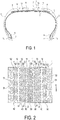
- is a meridian cross-sectional view illustrating a pneumatic tire according to an embodiment of the present invention.
- FIG. 2
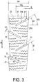
- is a developed view illustrating a tread pattern of the pneumatic tire in
FIG. 1 . - FIG. 3
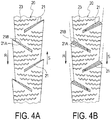
- is a plan view illustrating a rib formed in a center region of a tread portion in the pneumatic tire in
FIG. 1 . - FIG. 4
- illustrates a rib of the pneumatic tire in
FIG. 1 , whereFIG. 4A is a plan view illustrating a condition when driving, andFIG. 4B is a plan view illustrating a condition when braking. - FIG. 5
- is a cross-sectional view viewed in the direction of arrow V-V of
FIG. 3 . - FIG. 6
- is a cross-sectional view viewed in the direction of arrow VI-VI of
FIG. 3 . - The configuration of the present invention is described in detail below with reference to the accompanying drawings.
FIGS. 1 to 6 illustrate a pneumatic tire according to an embodiment of the present invention. The pneumatic tire of the present embodiment is a tire where a rotation direction R is specified. InFIG. 2 , CL represents a tire equator, and E represents a ground contacting end. - As illustrated in
FIG. 1 , a pneumatic tire of the present embodiment includes anannular tread portion 1 extending in a tire circumferential direction, a pair of sidewall portions 2, 2 disposed on both sides of thetread portion 1, and a pair ofbead portions - A carcass layer 4 is mounted between the pair of
bead portions bead cores 5 disposed thebead portions 3 from a tire inner side to a tire outer side. Abead filler 6 having a triangular cross-sectional shape formed from a rubber composition is disposed on an outer circumference of thebead core 5. - On the other hand, a plurality of belt layers 7 are embedded on an outer circumferential side of the carcass layer 4 in the
tread portion 1. The belt layers 7 include a plurality of reinforcing cords that are inclined with regard to the tire circumferential direction, and are disposed such that the reinforcing cords mutually intersect between layers. In the belt layers 7, an inclination angle of the reinforcing cords with regard to the tire circumferential direction range is set within a range of 10° to 40°, for example. A steel cord is preferably used as the reinforcing cord of the belt layer 7. In order to improve high-speed durability, at least one belt cover layer 8 formed by arranging the reinforcing cords at an angle of 5°or less for example with regard to the tire circumferential direction is disposed on the outer circumferential side of the belt layers 7. A nylon, aramid, or other organic fiber cord is preferably used as the reinforcing cord of the belt cover layer 8. - Note that the aforementioned tire internal structure indicates a representative example of the pneumatic tire, and is not limited thereto.
- As illustrated in
FIG. 2 , a pair of circumferentialmain grooves 11 that extend in a zigzagging shape along the tire circumferential direction on both sides of the tire equator CL, a pair of circumferentialmain grooves 12 extending in a zigzagging shape along the tire circumferential direction on an outer side in the tire width direction of the circumferentialmain grooves 11, and a pair of circumferentialauxiliary grooves 13 extending in a zigzagging shape along the tire circumferential direction between the circumferentialmain grooves 11 and circumferentialmain grooves 12 are formed on thetread portion 1. The circumferentialmain grooves auxiliary grooves 13 are grooves that are narrower than the circumferentialmain grooves - In the
tread portion 1, acenter rib 20 is demarcated between the pair of circumferentialmain grooves middle block row 30 is demarcated between the circumferentialmain grooves 11 and circumferentialauxiliary grooves 13, amiddle block row 40 is demarcated between the circumferentialauxiliary grooves 13 and circumferentialmain grooves 12, and ashoulder block row 50 is demarcated on an outer side in the tire width direction of the circumferentialmain grooves 12. - As illustrated in
FIG. 3 , a plurality ofclosed grooves 21 with a first end closing in thecenter rib 20 and a second end opening in one of the circumferentialmain grooves 11, and a plurality ofsipes 23 extending in the tire axial direction are formed on thecenter rib 20. The plurality ofclosed grooves 21 include grooves that open on a first side in the tire axial direction and grooves that open on a second side in the tire axial direction, and are alternatingly disposed along the tire circumferential direction. Herein, the leading side of thecenter rib 20 is the same side in the rotation direction R, and the trailing side is the opposite side in the rotation direction R. Theclosed grooves 21 are inclined in the tire axial direction such that closed ends thereof face the leading side (in other words, the rotation direction R side).Groove walls 21A on the leading side of theclosed grooves 21 protrude more outward in the tire axial direction thangroove walls 21B on the trailing side. Furthermore, a difference between an angle θ1 of thegroove walls 21A on the leading side of theclosed grooves 21 with regard to the tire axial direction and angle θ2 of thegroove walls 21B on the trailing side with regard to the tire axial direction is set within a range of 0° ≤ θ1 - θ2 ≤ 5°. In other words, theclosed grooves 21 have a structure where thegroove walls 21A on the leading side and groovewalls 21B on the trailing side are mutually parallel, or thegroove walls 21A on the leading side and groovewalls 21B on the trailing side gradually approach each other toward an opening end side. - A plurality of
lug grooves 31 extending in the tire axial direction are formed on themiddle block row 30, and a plurality ofblocks 32 are formed by thelug grooves 31. A plurality oflug grooves 41 extending in the tire axial direction are formed on themiddle block row 40, and a plurality ofblocks 42 are formed by thelug grooves 41. A plurality oflug grooves 51 extending in the tire axial direction are formed on theshoulder block row 50, and a plurality of blocks 52 are formed by thelug grooves 51. Thelug grooves sipes blocks sipes - In the aforementioned pneumatic tire, when a tread pattern with a specified rotation direction is used, the
center rib 20 is provided in the center region of thetread portion 1, the plurality ofclosed grooves 21 are formed on thecenter rib 20, theclosed grooves 21 are inclined with regard to the tire axial direction such that the closed ends thereof face the leading side, thegroove walls 21A on the leading side of theclosed grooves 21 protrude more outward in the tire axial direction than thegroove walls 21B on the trailing side, and the difference between the angle θ1 of thegroove walls 21A on the leading side of theclosed grooves 21 with regard to the tire axial direction and angle θ2 of thegroove walls 21B on the trailing side with regard to the tire axial direction is set within a range of 0° ≤ θ1 - θ2 ≤ 5, and therefore, thecenter rib 20 exhibits the following behaviors when braking and driving. - In other words, when driving, as illustrated in
FIG. 4A , slippage occurs on a road surface toward a direction S which is opposite from the rotation direction R with regard to thetread portion 1, and theclosed grooves 21 close such that a snow column inside theclosed grooves 21 is compressed by the slippage occurring between thetread portion 1 and the road surface. In other words, when braking, as illustrated inFIG. 4B , slippage occurs on the road surface in the same direction S as the rotation direction R with regard to thetread portion 1, and theclosed grooves 21 open such that a large amount of snow is introduced into theclosed grooves 21. Thus, the shear force of a snow column formed inside theclosed grooves 21 is increased, and therefore, a driving force and braking force during travel on snow increases due to the snow column shear force, and thus performance on snow can be effectively improved. - Herein, the difference between the angle θ1 of the
groove walls 21A on the leading side of theclosed grooves 21 with regard to the tire axial direction and angle θ2 of thegroove walls 21B on the trailing side with regard to the tire axial direction must be within a range of 0° ≤ θ1 - θ2 ≤ 5°. Thus, theclosed grooves 21 easily close when driving, and a sufficient amount of snow is introduced in theclosed grooves 21 when braking, and therefore, performance on snow can be effectively improved. When an angle difference (θ1 - θ2) of thegroove walls groove walls 21A on the leading side of theclosed grooves 21 is smaller than the angle θ2 of thegroove walls 21B on the trailing side is a negative value, an effect of compressing a snow column inside theclosed grooves 21 is reduced when driving, and conversely, when the angle difference (θ1 - θ2) is larger than 5°, an effect of incorporating snow inside theclosed grooves 21 is reduced when braking. - In the pneumatic tire, the JIS hardness of tread rubber configuring the
tread portion 1 is set within a range of 40 to 60, and more preferably set within a range of 45 to 55. If the JIS hardness of the tread rubber configuring thetread portion 1 is set within the aforementioned range, thetread portion 1 flexibly follows a road surface, and therefore, the tire effectively functions as a snow and ice tire. Furthermore, in the aforementioned pneumatic tire, the snow traction index STI is set at 180 or higher, and more preferably set within a range of 180 to 240. If the snow traction index STI is set within the aforementioned range, the tire effectively functions as a snow and ice tire. - In the aforementioned pneumatic tire, a ratio W/D of a groove width W with regard to a groove depth D of the
closed grooves 21 is preferably within a range of 0.10 to 0.30, as illustrated inFIG. 5 and FIG. 6 . Thus, theclosed grooves 21 appropriately deform in a ground contacting condition. As a result, theclosed grooves 21 easily close when driving, and a sufficient amount of snow is introduced in theclosed grooves 21 when braking, and therefore, performance on snow can be effectively improved. When the ratio W/D is smaller than 0.10, a snow column shear force based on theclosed grooves 21 is insufficient, and conversely, when the ratio is larger than 0.30, an effect of compressing snow inside theclosed grooves 21 is reduced. Note that if the groove depth D and groove width W of theclosed grooves 21 change based on a position of theclosed grooves 21 in a longitudinal direction, maximum values thereof are set as the groove depth D and groove width W. - As illustrated in
FIG. 3 , in the aforementioned pneumatic tire, a protruding amount E ofgroove walls 21A on the leading side of theclosed grooves 21 is preferably within a range of 5% to 15% of a width Wr of therib 20 in the tire axial direction, and more preferably within a range of 8% to 12%.
Thus, a sufficient amount of snow is introduced in theclosed grooves 21 when braking, and therefore, performance on snow can be effectively improved. When the protruding amount E is too small, an effect of incorporating snow into theclosed grooves 21 is reduced, and conversely, when the amount is too high, a location where the rigidity of therib 20 greatly differs is formed, and therefore, abnormal wear may occur. Note that the protruding amount E of thegroove walls 21A on the leading side of theclosed grooves 21 and the width Wr of therib 20 in the tire axial direction are both projected dimensions in the tire circumferential direction. - In the aforementioned pneumatic tire, the angle θ of a center line of the
closed grooves 21 with regard to the tire axial direction is preferably within a range of 25° to 65°, as illustrated inFIG. 3 . Thus, theclosed grooves 21 are sufficiently inclined with regard to the tire axial direction such that snow is easily introduced into theclosed grooves 21 when slippage occurs on a road surface when braking, and therefore, performance on snow can be effectively improved. When the angle θ of theclosed grooves 21 is smaller than 25°, an effect of introducing snow into theclosed groove 21 is reduced, and conversely, when the angle is larger than 65°, a reduction in rigidity of therib 20 becomes noticeable. - In the aforementioned pneumatic tire, the
closed grooves 21 preferably have a structure that gradually deepens toward the closed end thereof, as illustrated inFIG. 5 and FIG. 6 . In other words, a groove depth D2 of theclosed grooves 21 at a position on a closed end side is preferably relatively larger than a groove depth D1 at a position on the opening end side. Thus, a volume of theclosed grooves 21 on the closed end side is relatively increased, and an effect of guiding snow to the closed end side of theclosed grooves 21 is increased, and therefore, the snow column shear force can be effectively increased. Note that the groove depth D of theclosed grooves 21 is preferably within a range of 7 mm to 14 mm. - In the aforementioned pneumatic tire, a length Wg of the
closed grooves 21 in the tire axial direction is preferably within a range of 40% to 80% of the width Wr of therib 20 in the tire axial direction, and more preferably within a range of 50% to 70%, as illustrated inFIG. 3 . Thus, theclosed grooves 21 are sufficiently long, and therefore, the snow column shear force based on theclosed grooves 21 is sufficiently ensured, and thus performance on snow can be effectively improved. When the length Wg of theclosed grooves 21 is too small, the snow column shear force based on theclosed grooves 21 is insufficient, and conversely, when the length is too long, a reduction in rigidity of therib 20 becomes noticeable. Note that the length Wg of theclosed grooves 21 in the tire axial direction is a projected dimension in the tire circumferential direction. - In the aforementioned embodiment, a case where the
center rib 20 is disposed on the tire equator CL, and theclosed grooves 21 are provided with regard to thecenter rib 20 was described, but in the present invention, thecenter rib 20 where theclosed grooves 21 are formed is preferably at a position separated from the tire equator CL. However, if theclosed grooves 21 having the aforementioned structure are provided with regard to thecenter rib 20 positioned on the tire equator CL, the snow column shear force when braking and driving can be effectively increased. - For a pneumatic tire with a tire size of 225/65 R17 102Q, including: an annular-shape tread portion; a pair of sidewall portions; and a pair of bead portions; where
a JIS hardness of tread rubber configuring the tread portion is 51, a snow traction index is 200, and a rotation direction is specified; tires of Examples 1 to 8 where a rib positioned between a pair of circumferential grooves and continuous in the tire circumferential direction is demarcated in a center region of the tread portion, a plurality of closed grooves with a first end closing inside the rib and a second end opening in one of the circumferential grooves are formed in the rib, the closed grooves are inclined with regard to a tire axial direction such that the closed end faces a leading side, a groove wall of the closed groove on the leading side protrudes more outward in the tire axial direction than a groove wall on a trailing side, and a difference between an angle of the groove walls on the leading side of the closed grooves with regard to the tire axial direction and an angle of the groove walls on the trailing side with regard to the tire axial direction is within a range of 0° ≤ θ1 - θ2 ≤ 5° were prepared as illustrated inFIG. 2 . - In Examples 1 to 8, a difference (θ1 - θ2) between the angle θ1 of the groove walls on the leading side of the closed grooves and angle θ2 of the groove walls on the trailing side, a ratio (W/D) of a groove width W with regard to a groove depth D of the closed grooves, a ratio (E/Wr × 100%) of a protruding amount E of the groove walls on the leading side of the closed grooves with regard to a width Wr of the rib in the tire axial direction, an angle θ of a center line of the closed grooves with regard to the tire axial direction, a ratio (D2/D1) of a groove depth D2 of the
closed grooves 21 at a position on a closed end side with regard to a groove depth D1 at a position on an opening end side, and a ratio (Wg/Wr × 100%) of a length Wg of the closed grooves in the tire axial direction with regard to the width Wr of the rib in the tire axial direction were set as shown in Table 1. - For comparison, other than the difference (θ1 - θ2) of the angle θ1 of the groove walls on the leading side of the closed grooves and angle θ2 of the groove walls on the trailing side was set to -5°, a tire for a Conventional Example having a similar structure as Example 1 was prepared.
- The test tires were evaluated for braking performance on snow and driving performance on snow based on the following test methods, and the results thereof are collectively shown in Table 1. The evaluations were conducted under conditions where the test tires were assembled on wheels having a rim size of 17 x 7J, and mounted on a four-wheel drive vehicle with a 2400 cc engine displacement, and the air pressure after warm-up was set to 220 kPa.
- For the test tires, a braking distance from a condition traveling at a speed of 40 km/h on snow to stopped by performing ABS braking was measured. Using reciprocals of measurement values, the evaluation results were expressed as index values with the values of the Conventional Example being defined as 100. Larger index values indicate superior braking performance on snow.
- For the test tires, an acceleration test on snow was performed, and the time from a stopped condition to 40 km/h was measured. Using reciprocals of measurement values, the evaluation results were expressed as index values with the values of the Conventional Example being defined as 100. Larger index values indicate superior driving performance on snow.
[Table 1] Conventional Example Example 1 Example 2 Example 3 Example 4 Example 5 Example 6 Example 7 Example 8 θ1-θ2(°) -5 0 3 5 0 0 0 0 0 W/D 0.2 0.2 0.2 0.2 0.2 0.2 0.2 0.2 0.2 E/Wrx 100% 5 5 5 5 10 10 10 10 10 θ(°) 45 45 45 45 45 35 55 45 45 D2/D1 0.8 0.8 0.8 0.8 0.8 0.8 0.8 1.2 1.2 Wg/Wrx 100% 15 15 15 15 15 15 15 15 60 Braking performance on snow (index) 100 109 112 109 115 112 112 119 121 Driving performance on snow (index) 100 108 111 108 112 111 111 115 117 - As can be seen from Table 1, the tires of Examples 1 to 8 had both superior braking performance on snow and driving performance on snow as compared to the Conventional Example.
-
- 1 Tread portion
- 2 Sidewall portion
- 3 Bead portion
- 11, 12 Circumferential main groove
- 13 Circumferential auxiliary groove
- 20 Center rib
- 21 Closed groove
- 21A Groove wall on leading side
- 21B Groove wall on trailing side
- 23, 33, 43, 53 Sipe
- 30, 40, 50 Block row
- 31, 41, 51 Lug groove
- 32, 42, 52 Block
- CL Tire equator
- R Rotation direction
Claims (6)
- A pneumatic tire, comprising:an annular-shape tread portion extending in a tire circumferential direction;a pair of sidewall portions disposed on both sides of the tread portion; anda pair of bead portions disposed on an inner side in a tire radial direction of the sidewall portion;JIS hardness of tread rubber configuring the tread portion being within a range of 40 to 60, snow traction index based on grooves and sipes formed on the tread portion being 180 or higher, and a rotation direction being specified; whereina rib positioned between a pair of circumferential grooves and continuous in the tire circumferential direction is demarcated in a center region of the tread portion, a plurality of closed grooves with a first end closed inside the rib and a second end opening in one of the circumferential grooves are formed in the rib, the closed grooves are inclined with regard to a tire axial direction such that closed ends thereof face a leading side, a groove wall of the closed groove on the leading side protrudes more outward in the tire axial direction than a groove wall on a trailing side, and a difference between an angle θ1 of the groove walls on the leading side of the closed grooves with regard to the tire axial direction and an angle θ2 of the groove walls on the trailing side with regard to the tire axial direction is within a range of 0° ≤ θ1 - θ2 ≤ 5°.
- The pneumatic tire according to claim 1, wherein
a ratio W/D of a groove width W with regard to a groove depth D of the closed groove is within a range of 0.10 to 0.30. - The pneumatic tire according to claim 1 or 2, wherein
a protruding amount E of the groove wall on the leading side of the closed groove is within a range of 5% to 15% of a width Wr in the tire axial direction of the rib. - The pneumatic tire according to claims 1 to 3, wherein
an angle θ of a center line of the closed groove with regard to the tire axial direction is within a range of 25° to 65°. - The pneumatic tire according to any one of claims 1 to 4, wherein
the closed groove has a structure that gradually deepens toward the closed end thereof. - The pneumatic tire according to any one of claims 1 to 5, wherein
a length Wg of the closed groove in the tire axial direction is 40% to 80% of the width Wr of the rib in the tire axial direction.
Applications Claiming Priority (2)
| Application Number | Priority Date | Filing Date | Title |
|---|---|---|---|
| JP2015231722A JP6326399B2 (en) | 2015-11-27 | 2015-11-27 | Pneumatic tire |
| PCT/JP2016/084932 WO2017090715A1 (en) | 2015-11-27 | 2016-11-25 | Pneumatic tire |
Publications (3)
| Publication Number | Publication Date |
|---|---|
| EP3381719A1 true EP3381719A1 (en) | 2018-10-03 |
| EP3381719A4 EP3381719A4 (en) | 2019-05-01 |
| EP3381719B1 EP3381719B1 (en) | 2020-07-29 |
Family
ID=58763488
Family Applications (1)
| Application Number | Title | Priority Date | Filing Date |
|---|---|---|---|
| EP16868658.2A Active EP3381719B1 (en) | 2015-11-27 | 2016-11-25 | Pneumatic tire |
Country Status (6)
| Country | Link |
|---|---|
| US (1) | US11241917B2 (en) |
| EP (1) | EP3381719B1 (en) |
| JP (1) | JP6326399B2 (en) |
| CN (1) | CN108349328B (en) |
| RU (1) | RU2684990C1 (en) |
| WO (1) | WO2017090715A1 (en) |
Families Citing this family (6)
| Publication number | Priority date | Publication date | Assignee | Title |
|---|---|---|---|---|
| JP7031348B2 (en) * | 2018-02-14 | 2022-03-08 | 横浜ゴム株式会社 | Pneumatic tires |
| JP7283331B2 (en) | 2019-09-25 | 2023-05-30 | 横浜ゴム株式会社 | pneumatic tire |
| JP7431573B2 (en) * | 2019-12-19 | 2024-02-15 | 株式会社ブリヂストン | tire |
| JP6981509B1 (en) * | 2020-08-24 | 2021-12-15 | 横浜ゴム株式会社 | tire |
| US20220371380A1 (en) * | 2021-05-21 | 2022-11-24 | The Goodyear Tire & Rubber Company | Tread for a tire |
| CN115465021B (en) * | 2022-09-26 | 2023-07-04 | 中策橡胶集团股份有限公司 | Nail-inlaid snow tire capable of improving ground grabbing force |
Family Cites Families (25)
| Publication number | Priority date | Publication date | Assignee | Title |
|---|---|---|---|---|
| NL6812347A (en) | 1968-08-30 | 1970-03-03 | ||
| JPS60169305A (en) * | 1984-02-13 | 1985-09-02 | Ohtsu Tire & Rubber Co Ltd | Tread pattern of vehicle tire |
| US5435364A (en) * | 1990-12-28 | 1995-07-25 | Sumitomo Rubber Industries, Ltd. | Pneumatic radial tire with four main grooves |
| JP3559378B2 (en) * | 1996-02-29 | 2004-09-02 | 株式会社ブリヂストン | Pneumatic tire pair |
| JP4404398B2 (en) * | 1999-03-11 | 2010-01-27 | 株式会社ブリヂストン | Pneumatic tire |
| JP2005047397A (en) * | 2003-07-29 | 2005-02-24 | Sumitomo Rubber Ind Ltd | Pneumatic tire |
| JP2006176055A (en) * | 2004-12-24 | 2006-07-06 | Yokohama Rubber Co Ltd:The | Pneumatic tire |
| FR2894183B1 (en) * | 2005-12-06 | 2008-02-15 | Michelin Soc Tech | TIRE TREAD FOR PNEUMATIC HEAVY WEIGHT |
| JP2009012055A (en) | 2007-07-06 | 2009-01-22 | Seiko Epson Corp | Substrate dividing method and laser irradiation apparatus |
| JP4107393B1 (en) * | 2007-10-12 | 2008-06-25 | 横浜ゴム株式会社 | Pneumatic tire |
| JP5045383B2 (en) | 2007-11-15 | 2012-10-10 | 横浜ゴム株式会社 | Pneumatic tire |
| JP5239504B2 (en) | 2008-05-16 | 2013-07-17 | 横浜ゴム株式会社 | Pneumatic tire |
| JP5102711B2 (en) | 2008-07-16 | 2012-12-19 | 株式会社ブリヂストン | Pneumatic tire |
| JP2010167930A (en) | 2009-01-23 | 2010-08-05 | Yokohama Rubber Co Ltd:The | Pneumatic tire |
| JP4471031B1 (en) | 2009-02-16 | 2010-06-02 | 横浜ゴム株式会社 | Pneumatic tire |
| JP4829994B2 (en) * | 2009-04-06 | 2011-12-07 | 住友ゴム工業株式会社 | Pneumatic tire |
| JP5144720B2 (en) * | 2010-06-17 | 2013-02-13 | 住友ゴム工業株式会社 | Pneumatic tire |
| JP5285739B2 (en) * | 2011-04-28 | 2013-09-11 | 住友ゴム工業株式会社 | Pneumatic tire |
| JP5905673B2 (en) | 2011-07-07 | 2016-04-20 | 株式会社ブリヂストン | tire |
| JP5083451B1 (en) * | 2011-12-07 | 2012-11-28 | 横浜ゴム株式会社 | Pneumatic tire |
| JP2014108653A (en) * | 2012-11-30 | 2014-06-12 | Yokohama Rubber Co Ltd:The | Pneumatic tire |
| JP6123405B2 (en) * | 2013-03-26 | 2017-05-10 | 横浜ゴム株式会社 | Pneumatic tire |
| JP5827645B2 (en) * | 2013-07-16 | 2015-12-02 | 住友ゴム工業株式会社 | Pneumatic tire |
| JP5975004B2 (en) * | 2013-09-17 | 2016-08-23 | 横浜ゴム株式会社 | Pneumatic tire |
| JP2015101211A (en) * | 2013-11-25 | 2015-06-04 | 横浜ゴム株式会社 | Pneumatic tire |
-
2015
- 2015-11-27 JP JP2015231722A patent/JP6326399B2/en active Active
-
2016
- 2016-11-25 US US15/778,620 patent/US11241917B2/en active Active
- 2016-11-25 RU RU2018123159A patent/RU2684990C1/en active
- 2016-11-25 EP EP16868658.2A patent/EP3381719B1/en active Active
- 2016-11-25 CN CN201680063528.0A patent/CN108349328B/en active Active
- 2016-11-25 WO PCT/JP2016/084932 patent/WO2017090715A1/en not_active Ceased
Also Published As
| Publication number | Publication date |
|---|---|
| RU2684990C1 (en) | 2019-04-16 |
| US11241917B2 (en) | 2022-02-08 |
| CN108349328A (en) | 2018-07-31 |
| JP2017095044A (en) | 2017-06-01 |
| WO2017090715A1 (en) | 2017-06-01 |
| CN108349328B (en) | 2020-06-16 |
| US20180354309A1 (en) | 2018-12-13 |
| EP3381719B1 (en) | 2020-07-29 |
| JP6326399B2 (en) | 2018-05-16 |
| EP3381719A4 (en) | 2019-05-01 |
Similar Documents
| Publication | Publication Date | Title |
|---|---|---|
| CN103241070B (en) | Pneumatic tire | |
| EP3202592B1 (en) | Pneumatic radial tire for passenger vehicle | |
| EP3205515B1 (en) | Pneumatic radial tire for passenger vehicle | |
| EP3381719B1 (en) | Pneumatic tire | |
| AU2015329071B2 (en) | Pneumatic tire | |
| CN104395111B (en) | Pneumatic tire | |
| US10179483B2 (en) | Pneumatic tire | |
| EP2881266B1 (en) | Pneumatic tire | |
| CN104955659A (en) | Pneumatic tire | |
| JP2013189131A (en) | Pneumatic tire | |
| EP2738016A1 (en) | Pneumatic radial tire for passenger vehicle and method for using same | |
| AU2015329145A1 (en) | Pneumatic tire | |
| EP2957435B1 (en) | Heavy duty tire | |
| EP3845397B1 (en) | Pneumatic tire | |
| JP2019043516A (en) | Pneumatic tire | |
| US12533912B2 (en) | Tire | |
| EP3486096B1 (en) | Pneumatic tire | |
| CN113474185B (en) | Pneumatic tire | |
| JP6477952B2 (en) | Pneumatic tire | |
| JP7357840B2 (en) | tire | |
| JP6593058B2 (en) | Pneumatic tire | |
| EP2248682B1 (en) | Studless tire | |
| JP2013216184A (en) | Pneumatic tire | |
| CN115503399A (en) | Tyre for vehicle wheels |
Legal Events
| Date | Code | Title | Description |
|---|---|---|---|
| STAA | Information on the status of an ep patent application or granted ep patent |
Free format text: STATUS: THE INTERNATIONAL PUBLICATION HAS BEEN MADE |
|
| PUAI | Public reference made under article 153(3) epc to a published international application that has entered the european phase |
Free format text: ORIGINAL CODE: 0009012 |
|
| STAA | Information on the status of an ep patent application or granted ep patent |
Free format text: STATUS: REQUEST FOR EXAMINATION WAS MADE |
|
| 17P | Request for examination filed |
Effective date: 20180627 |
|
| AK | Designated contracting states |
Kind code of ref document: A1 Designated state(s): AL AT BE BG CH CY CZ DE DK EE ES FI FR GB GR HR HU IE IS IT LI LT LU LV MC MK MT NL NO PL PT RO RS SE SI SK SM TR |
|
| AX | Request for extension of the european patent |
Extension state: BA ME |
|
| DAV | Request for validation of the european patent (deleted) | ||
| DAX | Request for extension of the european patent (deleted) | ||
| A4 | Supplementary search report drawn up and despatched |
Effective date: 20190328 |
|
| RIC1 | Information provided on ipc code assigned before grant |
Ipc: B60C 11/13 20060101AFI20190322BHEP Ipc: B60C 11/03 20060101ALI20190322BHEP |
|
| GRAP | Despatch of communication of intention to grant a patent |
Free format text: ORIGINAL CODE: EPIDOSNIGR1 |
|
| STAA | Information on the status of an ep patent application or granted ep patent |
Free format text: STATUS: GRANT OF PATENT IS INTENDED |
|
| INTG | Intention to grant announced |
Effective date: 20191205 |
|
| GRAJ | Information related to disapproval of communication of intention to grant by the applicant or resumption of examination proceedings by the epo deleted |
Free format text: ORIGINAL CODE: EPIDOSDIGR1 |
|
| STAA | Information on the status of an ep patent application or granted ep patent |
Free format text: STATUS: REQUEST FOR EXAMINATION WAS MADE |
|
| GRAP | Despatch of communication of intention to grant a patent |
Free format text: ORIGINAL CODE: EPIDOSNIGR1 |
|
| STAA | Information on the status of an ep patent application or granted ep patent |
Free format text: STATUS: GRANT OF PATENT IS INTENDED |
|
| INTC | Intention to grant announced (deleted) | ||
| INTG | Intention to grant announced |
Effective date: 20200331 |
|
| RIN1 | Information on inventor provided before grant (corrected) |
Inventor name: HONDA NARUHIKO |
|
| GRAS | Grant fee paid |
Free format text: ORIGINAL CODE: EPIDOSNIGR3 |
|
| GRAA | (expected) grant |
Free format text: ORIGINAL CODE: 0009210 |
|
| STAA | Information on the status of an ep patent application or granted ep patent |
Free format text: STATUS: THE PATENT HAS BEEN GRANTED |
|
| AK | Designated contracting states |
Kind code of ref document: B1 Designated state(s): AL AT BE BG CH CY CZ DE DK EE ES FI FR GB GR HR HU IE IS IT LI LT LU LV MC MK MT NL NO PL PT RO RS SE SI SK SM TR |
|
| REG | Reference to a national code |
Ref country code: CH Ref legal event code: EP |
|
| REG | Reference to a national code |
Ref country code: AT Ref legal event code: REF Ref document number: 1295370 Country of ref document: AT Kind code of ref document: T Effective date: 20200815 |
|
| REG | Reference to a national code |
Ref country code: IE Ref legal event code: FG4D |
|
| REG | Reference to a national code |
Ref country code: DE Ref legal event code: R096 Ref document number: 602016041065 Country of ref document: DE |
|
| REG | Reference to a national code |
Ref country code: FI Ref legal event code: FGE |
|
| REG | Reference to a national code |
Ref country code: LT Ref legal event code: MG4D |
|
| REG | Reference to a national code |
Ref country code: NL Ref legal event code: MP Effective date: 20200729 |
|
| REG | Reference to a national code |
Ref country code: AT Ref legal event code: MK05 Ref document number: 1295370 Country of ref document: AT Kind code of ref document: T Effective date: 20200729 |
|
| PG25 | Lapsed in a contracting state [announced via postgrant information from national office to epo] |
Ref country code: PT Free format text: LAPSE BECAUSE OF FAILURE TO SUBMIT A TRANSLATION OF THE DESCRIPTION OR TO PAY THE FEE WITHIN THE PRESCRIBED TIME-LIMIT Effective date: 20201130 Ref country code: GR Free format text: LAPSE BECAUSE OF FAILURE TO SUBMIT A TRANSLATION OF THE DESCRIPTION OR TO PAY THE FEE WITHIN THE PRESCRIBED TIME-LIMIT Effective date: 20201030 Ref country code: HR Free format text: LAPSE BECAUSE OF FAILURE TO SUBMIT A TRANSLATION OF THE DESCRIPTION OR TO PAY THE FEE WITHIN THE PRESCRIBED TIME-LIMIT Effective date: 20200729 Ref country code: SE Free format text: LAPSE BECAUSE OF FAILURE TO SUBMIT A TRANSLATION OF THE DESCRIPTION OR TO PAY THE FEE WITHIN THE PRESCRIBED TIME-LIMIT Effective date: 20200729 Ref country code: BG Free format text: LAPSE BECAUSE OF FAILURE TO SUBMIT A TRANSLATION OF THE DESCRIPTION OR TO PAY THE FEE WITHIN THE PRESCRIBED TIME-LIMIT Effective date: 20201029 Ref country code: NO Free format text: LAPSE BECAUSE OF FAILURE TO SUBMIT A TRANSLATION OF THE DESCRIPTION OR TO PAY THE FEE WITHIN THE PRESCRIBED TIME-LIMIT Effective date: 20201029 Ref country code: LT Free format text: LAPSE BECAUSE OF FAILURE TO SUBMIT A TRANSLATION OF THE DESCRIPTION OR TO PAY THE FEE WITHIN THE PRESCRIBED TIME-LIMIT Effective date: 20200729 Ref country code: ES Free format text: LAPSE BECAUSE OF FAILURE TO SUBMIT A TRANSLATION OF THE DESCRIPTION OR TO PAY THE FEE WITHIN THE PRESCRIBED TIME-LIMIT Effective date: 20200729 Ref country code: AT Free format text: LAPSE BECAUSE OF FAILURE TO SUBMIT A TRANSLATION OF THE DESCRIPTION OR TO PAY THE FEE WITHIN THE PRESCRIBED TIME-LIMIT Effective date: 20200729 |
|
| PG25 | Lapsed in a contracting state [announced via postgrant information from national office to epo] |
Ref country code: RS Free format text: LAPSE BECAUSE OF FAILURE TO SUBMIT A TRANSLATION OF THE DESCRIPTION OR TO PAY THE FEE WITHIN THE PRESCRIBED TIME-LIMIT Effective date: 20200729 Ref country code: PL Free format text: LAPSE BECAUSE OF FAILURE TO SUBMIT A TRANSLATION OF THE DESCRIPTION OR TO PAY THE FEE WITHIN THE PRESCRIBED TIME-LIMIT Effective date: 20200729 Ref country code: LV Free format text: LAPSE BECAUSE OF FAILURE TO SUBMIT A TRANSLATION OF THE DESCRIPTION OR TO PAY THE FEE WITHIN THE PRESCRIBED TIME-LIMIT Effective date: 20200729 Ref country code: IS Free format text: LAPSE BECAUSE OF FAILURE TO SUBMIT A TRANSLATION OF THE DESCRIPTION OR TO PAY THE FEE WITHIN THE PRESCRIBED TIME-LIMIT Effective date: 20201129 |
|
| PG25 | Lapsed in a contracting state [announced via postgrant information from national office to epo] |
Ref country code: NL Free format text: LAPSE BECAUSE OF FAILURE TO SUBMIT A TRANSLATION OF THE DESCRIPTION OR TO PAY THE FEE WITHIN THE PRESCRIBED TIME-LIMIT Effective date: 20200729 |
|
| PG25 | Lapsed in a contracting state [announced via postgrant information from national office to epo] |
Ref country code: DK Free format text: LAPSE BECAUSE OF FAILURE TO SUBMIT A TRANSLATION OF THE DESCRIPTION OR TO PAY THE FEE WITHIN THE PRESCRIBED TIME-LIMIT Effective date: 20200729 Ref country code: CZ Free format text: LAPSE BECAUSE OF FAILURE TO SUBMIT A TRANSLATION OF THE DESCRIPTION OR TO PAY THE FEE WITHIN THE PRESCRIBED TIME-LIMIT Effective date: 20200729 Ref country code: RO Free format text: LAPSE BECAUSE OF FAILURE TO SUBMIT A TRANSLATION OF THE DESCRIPTION OR TO PAY THE FEE WITHIN THE PRESCRIBED TIME-LIMIT Effective date: 20200729 Ref country code: EE Free format text: LAPSE BECAUSE OF FAILURE TO SUBMIT A TRANSLATION OF THE DESCRIPTION OR TO PAY THE FEE WITHIN THE PRESCRIBED TIME-LIMIT Effective date: 20200729 Ref country code: IT Free format text: LAPSE BECAUSE OF FAILURE TO SUBMIT A TRANSLATION OF THE DESCRIPTION OR TO PAY THE FEE WITHIN THE PRESCRIBED TIME-LIMIT Effective date: 20200729 Ref country code: SM Free format text: LAPSE BECAUSE OF FAILURE TO SUBMIT A TRANSLATION OF THE DESCRIPTION OR TO PAY THE FEE WITHIN THE PRESCRIBED TIME-LIMIT Effective date: 20200729 |
|
| REG | Reference to a national code |
Ref country code: DE Ref legal event code: R097 Ref document number: 602016041065 Country of ref document: DE |
|
| PG25 | Lapsed in a contracting state [announced via postgrant information from national office to epo] |
Ref country code: AL Free format text: LAPSE BECAUSE OF FAILURE TO SUBMIT A TRANSLATION OF THE DESCRIPTION OR TO PAY THE FEE WITHIN THE PRESCRIBED TIME-LIMIT Effective date: 20200729 |
|
| PLBE | No opposition filed within time limit |
Free format text: ORIGINAL CODE: 0009261 |
|
| STAA | Information on the status of an ep patent application or granted ep patent |
Free format text: STATUS: NO OPPOSITION FILED WITHIN TIME LIMIT |
|
| PG25 | Lapsed in a contracting state [announced via postgrant information from national office to epo] |
Ref country code: SK Free format text: LAPSE BECAUSE OF FAILURE TO SUBMIT A TRANSLATION OF THE DESCRIPTION OR TO PAY THE FEE WITHIN THE PRESCRIBED TIME-LIMIT Effective date: 20200729 Ref country code: MC Free format text: LAPSE BECAUSE OF FAILURE TO SUBMIT A TRANSLATION OF THE DESCRIPTION OR TO PAY THE FEE WITHIN THE PRESCRIBED TIME-LIMIT Effective date: 20200729 |
|
| REG | Reference to a national code |
Ref country code: CH Ref legal event code: PL |
|
| 26N | No opposition filed |
Effective date: 20210430 |
|
| GBPC | Gb: european patent ceased through non-payment of renewal fee |
Effective date: 20201125 |
|
| PG25 | Lapsed in a contracting state [announced via postgrant information from national office to epo] |
Ref country code: LU Free format text: LAPSE BECAUSE OF NON-PAYMENT OF DUE FEES Effective date: 20201125 |
|
| REG | Reference to a national code |
Ref country code: BE Ref legal event code: MM Effective date: 20201130 |
|
| PG25 | Lapsed in a contracting state [announced via postgrant information from national office to epo] |
Ref country code: LI Free format text: LAPSE BECAUSE OF NON-PAYMENT OF DUE FEES Effective date: 20201130 Ref country code: SI Free format text: LAPSE BECAUSE OF FAILURE TO SUBMIT A TRANSLATION OF THE DESCRIPTION OR TO PAY THE FEE WITHIN THE PRESCRIBED TIME-LIMIT Effective date: 20200729 Ref country code: CH Free format text: LAPSE BECAUSE OF NON-PAYMENT OF DUE FEES Effective date: 20201130 |
|
| PG25 | Lapsed in a contracting state [announced via postgrant information from national office to epo] |
Ref country code: IE Free format text: LAPSE BECAUSE OF NON-PAYMENT OF DUE FEES Effective date: 20201125 Ref country code: FR Free format text: LAPSE BECAUSE OF NON-PAYMENT OF DUE FEES Effective date: 20201130 |
|
| PG25 | Lapsed in a contracting state [announced via postgrant information from national office to epo] |
Ref country code: GB Free format text: LAPSE BECAUSE OF NON-PAYMENT OF DUE FEES Effective date: 20201125 |
|
| PG25 | Lapsed in a contracting state [announced via postgrant information from national office to epo] |
Ref country code: IS Free format text: LAPSE BECAUSE OF FAILURE TO SUBMIT A TRANSLATION OF THE DESCRIPTION OR TO PAY THE FEE WITHIN THE PRESCRIBED TIME-LIMIT Effective date: 20201129 Ref country code: TR Free format text: LAPSE BECAUSE OF FAILURE TO SUBMIT A TRANSLATION OF THE DESCRIPTION OR TO PAY THE FEE WITHIN THE PRESCRIBED TIME-LIMIT Effective date: 20200729 Ref country code: MT Free format text: LAPSE BECAUSE OF FAILURE TO SUBMIT A TRANSLATION OF THE DESCRIPTION OR TO PAY THE FEE WITHIN THE PRESCRIBED TIME-LIMIT Effective date: 20200729 Ref country code: CY Free format text: LAPSE BECAUSE OF FAILURE TO SUBMIT A TRANSLATION OF THE DESCRIPTION OR TO PAY THE FEE WITHIN THE PRESCRIBED TIME-LIMIT Effective date: 20200729 |
|
| PG25 | Lapsed in a contracting state [announced via postgrant information from national office to epo] |
Ref country code: MK Free format text: LAPSE BECAUSE OF FAILURE TO SUBMIT A TRANSLATION OF THE DESCRIPTION OR TO PAY THE FEE WITHIN THE PRESCRIBED TIME-LIMIT Effective date: 20200729 |
|
| PG25 | Lapsed in a contracting state [announced via postgrant information from national office to epo] |
Ref country code: BE Free format text: LAPSE BECAUSE OF NON-PAYMENT OF DUE FEES Effective date: 20201130 |
|
| P01 | Opt-out of the competence of the unified patent court (upc) registered |
Effective date: 20230512 |
|
| PGFP | Annual fee paid to national office [announced via postgrant information from national office to epo] |
Ref country code: DE Payment date: 20250930 Year of fee payment: 10 |
|
| PGFP | Annual fee paid to national office [announced via postgrant information from national office to epo] |
Ref country code: FI Payment date: 20251113 Year of fee payment: 10 |