EP3381577A1 - Hot-rolled steel sheet and method for manufacturing same - Google Patents
Hot-rolled steel sheet and method for manufacturing same Download PDFInfo
- Publication number
- EP3381577A1 EP3381577A1 EP16868476.9A EP16868476A EP3381577A1 EP 3381577 A1 EP3381577 A1 EP 3381577A1 EP 16868476 A EP16868476 A EP 16868476A EP 3381577 A1 EP3381577 A1 EP 3381577A1
- Authority
- EP
- European Patent Office
- Prior art keywords
- steel sheet
- hot
- rolled steel
- width
- coil
- Prior art date
- Legal status (The legal status is an assumption and is not a legal conclusion. Google has not performed a legal analysis and makes no representation as to the accuracy of the status listed.)
- Granted
Links
Images




Classifications
-
- B—PERFORMING OPERATIONS; TRANSPORTING
- B21—MECHANICAL METAL-WORKING WITHOUT ESSENTIALLY REMOVING MATERIAL; PUNCHING METAL
- B21B—ROLLING OF METAL
- B21B1/00—Metal-rolling methods or mills for making semi-finished products of solid or profiled cross-section; Sequence of operations in milling trains; Layout of rolling-mill plant, e.g. grouping of stands; Succession of passes or of sectional pass alternations
- B21B1/22—Metal-rolling methods or mills for making semi-finished products of solid or profiled cross-section; Sequence of operations in milling trains; Layout of rolling-mill plant, e.g. grouping of stands; Succession of passes or of sectional pass alternations for rolling plates, strips, bands or sheets of indefinite length
- B21B1/24—Metal-rolling methods or mills for making semi-finished products of solid or profiled cross-section; Sequence of operations in milling trains; Layout of rolling-mill plant, e.g. grouping of stands; Succession of passes or of sectional pass alternations for rolling plates, strips, bands or sheets of indefinite length in a continuous or semi-continuous process
- B21B1/26—Metal-rolling methods or mills for making semi-finished products of solid or profiled cross-section; Sequence of operations in milling trains; Layout of rolling-mill plant, e.g. grouping of stands; Succession of passes or of sectional pass alternations for rolling plates, strips, bands or sheets of indefinite length in a continuous or semi-continuous process by hot-rolling, e.g. Steckel hot mill
-
- B—PERFORMING OPERATIONS; TRANSPORTING
- B21—MECHANICAL METAL-WORKING WITHOUT ESSENTIALLY REMOVING MATERIAL; PUNCHING METAL
- B21B—ROLLING OF METAL
- B21B37/00—Control devices or methods specially adapted for metal-rolling mills or the work produced thereby
- B21B37/72—Rear end control; Front end control
-
- B—PERFORMING OPERATIONS; TRANSPORTING
- B21—MECHANICAL METAL-WORKING WITHOUT ESSENTIALLY REMOVING MATERIAL; PUNCHING METAL
- B21B—ROLLING OF METAL
- B21B1/00—Metal-rolling methods or mills for making semi-finished products of solid or profiled cross-section; Sequence of operations in milling trains; Layout of rolling-mill plant, e.g. grouping of stands; Succession of passes or of sectional pass alternations
- B21B1/38—Metal-rolling methods or mills for making semi-finished products of solid or profiled cross-section; Sequence of operations in milling trains; Layout of rolling-mill plant, e.g. grouping of stands; Succession of passes or of sectional pass alternations for rolling sheets of limited length, e.g. folded sheets, superimposed sheets, pack rolling
-
- B—PERFORMING OPERATIONS; TRANSPORTING
- B21—MECHANICAL METAL-WORKING WITHOUT ESSENTIALLY REMOVING MATERIAL; PUNCHING METAL
- B21B—ROLLING OF METAL
- B21B15/00—Arrangements for performing additional metal-working operations specially combined with or arranged in, or specially adapted for use in connection with, metal-rolling mills
- B21B15/0007—Cutting or shearing the product
-
- B—PERFORMING OPERATIONS; TRANSPORTING
- B21—MECHANICAL METAL-WORKING WITHOUT ESSENTIALLY REMOVING MATERIAL; PUNCHING METAL
- B21B—ROLLING OF METAL
- B21B1/00—Metal-rolling methods or mills for making semi-finished products of solid or profiled cross-section; Sequence of operations in milling trains; Layout of rolling-mill plant, e.g. grouping of stands; Succession of passes or of sectional pass alternations
- B21B1/22—Metal-rolling methods or mills for making semi-finished products of solid or profiled cross-section; Sequence of operations in milling trains; Layout of rolling-mill plant, e.g. grouping of stands; Succession of passes or of sectional pass alternations for rolling plates, strips, bands or sheets of indefinite length
- B21B2001/225—Metal-rolling methods or mills for making semi-finished products of solid or profiled cross-section; Sequence of operations in milling trains; Layout of rolling-mill plant, e.g. grouping of stands; Succession of passes or of sectional pass alternations for rolling plates, strips, bands or sheets of indefinite length by hot-rolling
-
- B—PERFORMING OPERATIONS; TRANSPORTING
- B21—MECHANICAL METAL-WORKING WITHOUT ESSENTIALLY REMOVING MATERIAL; PUNCHING METAL
- B21B—ROLLING OF METAL
- B21B15/00—Arrangements for performing additional metal-working operations specially combined with or arranged in, or specially adapted for use in connection with, metal-rolling mills
- B21B15/0007—Cutting or shearing the product
- B21B2015/0014—Cutting or shearing the product transversely to the rolling direction
-
- B—PERFORMING OPERATIONS; TRANSPORTING
- B21—MECHANICAL METAL-WORKING WITHOUT ESSENTIALLY REMOVING MATERIAL; PUNCHING METAL
- B21B—ROLLING OF METAL
- B21B15/00—Arrangements for performing additional metal-working operations specially combined with or arranged in, or specially adapted for use in connection with, metal-rolling mills
- B21B2015/0064—Uncoiling the rolled product
-
- B—PERFORMING OPERATIONS; TRANSPORTING
- B21—MECHANICAL METAL-WORKING WITHOUT ESSENTIALLY REMOVING MATERIAL; PUNCHING METAL
- B21B—ROLLING OF METAL
- B21B2263/00—Shape of product
- B21B2263/20—End shape; fish tail; tongue
-
- B—PERFORMING OPERATIONS; TRANSPORTING
- B21—MECHANICAL METAL-WORKING WITHOUT ESSENTIALLY REMOVING MATERIAL; PUNCHING METAL
- B21C—MANUFACTURE OF METAL SHEETS, WIRE, RODS, TUBES, PROFILES OR LIKE SEMI-MANUFACTURED PRODUCTS OTHERWISE THAN BY ROLLING; AUXILIARY OPERATIONS USED IN CONNECTION WITH METAL-WORKING WITHOUT ESSENTIALLY REMOVING MATERIAL
- B21C47/00—Winding-up, coiling or winding-off metal wire, metal band or other flexible metal material characterised by features relevant to metal processing only
- B21C47/16—Unwinding or uncoiling
- B21C47/18—Unwinding or uncoiling from reels or drums
-
- C—CHEMISTRY; METALLURGY
- C21—METALLURGY OF IRON
- C21D—MODIFYING THE PHYSICAL STRUCTURE OF FERROUS METALS; GENERAL DEVICES FOR HEAT TREATMENT OF FERROUS OR NON-FERROUS METALS OR ALLOYS; MAKING METAL MALLEABLE, e.g. BY DECARBURISATION OR TEMPERING
- C21D8/00—Modifying the physical properties of ferrous metals or ferrous alloys by deformation combined with, or followed by, heat treatment
- C21D8/02—Modifying the physical properties of ferrous metals or ferrous alloys by deformation combined with, or followed by, heat treatment during manufacturing of plates or strips
- C21D8/0221—Modifying the physical properties of ferrous metals or ferrous alloys by deformation combined with, or followed by, heat treatment during manufacturing of plates or strips characterised by the working steps
- C21D8/0226—Hot rolling
-
- C—CHEMISTRY; METALLURGY
- C21—METALLURGY OF IRON
- C21D—MODIFYING THE PHYSICAL STRUCTURE OF FERROUS METALS; GENERAL DEVICES FOR HEAT TREATMENT OF FERROUS OR NON-FERROUS METALS OR ALLOYS; MAKING METAL MALLEABLE, e.g. BY DECARBURISATION OR TEMPERING
- C21D8/00—Modifying the physical properties of ferrous metals or ferrous alloys by deformation combined with, or followed by, heat treatment
- C21D8/02—Modifying the physical properties of ferrous metals or ferrous alloys by deformation combined with, or followed by, heat treatment during manufacturing of plates or strips
- C21D8/0247—Modifying the physical properties of ferrous metals or ferrous alloys by deformation combined with, or followed by, heat treatment during manufacturing of plates or strips characterised by the heat treatment
- C21D8/0263—Modifying the physical properties of ferrous metals or ferrous alloys by deformation combined with, or followed by, heat treatment during manufacturing of plates or strips characterised by the heat treatment following hot rolling
Definitions
- the present invention relates to a hot-rolled steel sheet which is rolled by rough rolling and cut in unsteady portions at its longitudinal head and tail ends, and a method for manufacturing the same and, more particularly, to such technologies suitable for a thick, wide, high-strength hot-rolled steel sheet.
- Hot-rolled steel sheets for line pipe materials of this type require high-strength, extremely thick specifications in terms of efficient transportation of, for example, crude oil and natural gas. Furthermore, since pipelines may be laid in seismic zones, the line pipe materials also need to be tough. Such hot-rolled steel sheets for line pipe materials need to satisfy, for example, X65-grade strength stipulated by API (American Petroleum Institute) standards, and examples of such hot-rolled steel sheets include a hot-rolled steel sheet disclosed in PTL 1.
- a hot-rolled steel sheet for a line pipe material, as disclosed in PTL 1 is generally thick, wide, and strong.
- a hot-rolled steel sheet for a line pipe material is once wound around a coil, which is then unwound to form a steel pipe.
- the coil of the hot-rolled steel sheet is unwound by a coil opener, but since such a hot-rolled steel sheet for a line pipe material is extremely thick, wide, and strong, the allowable load of the coil opener may be exceeded during this unwinding.
- the present invention has been made in consideration of the above-described problem, and has as its object to provide a hot-rolled steel sheet which does not exceed the allowable load of a coil opener during unwinding, even with a coil of a thick, wide, high-strength hot-rolled steel sheet, and a method for manufacturing the same.
- the inventors of the present invention conducted a close examination for a hot-rolled steel sheet which facilitates unwinding by a coil opener by shaping a crop portion formed on the trailing end of the steel sheet in the transport direction in a rough rolling step before finish rolling into a fish tail-shaped structure, and cutting the intermediate portion between the bottom of a recess and the tips of projections in the fish tail-shaped structure to form a recess at the widthwise center of the unwinding end of the hot-rolled steel sheet in the wound coil.
- a coil is generally unwound by picking up and bending the rearmost end of a hot-rolled steel sheet by a coil opener.
- the coil opener can easily cause pickup deformation and bending deformation.
- a crop portion formed on the trailing end of the steel sheet in the transport direction can be shaped into a fish tail-shaped structure as illustrated in FIG. 6A .
- the trailing end of the hot-rolled steel sheet can be formed with its widthwise center recessed more than its two widthwise ends.
- An error occurs between the target cut position and the position where the blade of the crop shear actually comes into contact with the steel sheet, and, therefore, depending on the cut position accuracy of the crop shear, swinging down the blade of the crop shear while aiming at the target cut position of the fish tail-shaped crop portion, may result in full-width sheet cutting or a cutting miss because of a failure of contact with the fish tail-shaped structure of the crop portion.
- the fish tail length is set large enough to cause neither full-width sheet cutting nor a cutting miss even when an error occurs between the target cut position and the actual cut position.
- the target cut position needs to be set in consideration of the error.
- the target cut position needs to be set to allow the blade of the crop shear to be swung down with neither full-width sheet cutting nor a cutting miss even when the cut position of the crop shear deviates from the target cut position.
- the present invention has been made based on the above-mentioned finding and includes the following gist.
- the present invention in one aspect provides a hot-rolled steel sheet cut in unsteady portions at a longitudinal head end and a longitudinal tail end in cutting after rough rolling, having a width of 1,200 mm to 2,300 mm, a thickness of 13 mm to 25.4 mm, and at least an API standard X65-grade strength, and used in a state of being unwound after having been wound around a coil, wherein at least a longitudinal end corresponding to start of unwinding includes a portion at a widthwise center recessed inwards in a longitudinal direction with respect to two widthwise ends, projection sizes of the two widthwise ends with respect to the recessed portion at the widthwise center are 20 mm to 295 mm, and a sum of widths of projecting portions at the two widthwise ends is 1/4 to 1/2 of the width of the sheet.
- the present invention in another aspect provides a method for manufacturing a hot-rolled steel sheet, the method including: rough rolling; finish rolling; and winding, in which the steel sheet cut by a crop shear in a crop portion on a trailing end of the steel sheet in a transport direction after the rough rolling and before the finish rolling, finish-rolled in the finish rolling, and wound in the winding has a width of 1,200 mm to 2,300 mm, a thickness of 13 mm to 25.4 mm, and at least an API standard X65-grade strength, wherein in the rough rolling, the crop portion formed on the trailing end of the steel sheet in the transport direction is shaped into a fish tail-shaped structure by width reduction rolling using a width rolling mill and horizontal rolling using a horizontal rough rolling mill, and shaping is performed so that a minimum length L (mm) from a bottom of a recess to a tip of a projection in the fish tail-shaped structure satisfies: 2 X + 5 ⁇ L ⁇ 300 for 0 ⁇ X ⁇ 90 where
- the present invention even a coil of a thick, wide, high-strength steel sheet can be prevented from exceeding the allowable load of a coil opener during unwinding. Further, the steel sheet can be stably unwound without any extensive equipment improvement such as reinforcement of the coil opener.
- FIG. 1 is a front view illustrating a hot-rolled steel sheet in this embodiment wrapped around a coil, as mounted on an uncoiler
- FIG. 2 is a plan view of the uncoiler illustrated in FIG. 1
- the uncoiler includes cradle rollers 1 which support a coil C of a hot-rolled steel sheet S, a payoff reel 2 inserted into the coil C, and a coil opener 3 inserted at the unwinding end of the hot-rolled steel sheet S wound around the coil C.
- the payoff reel 2 and the cradle rollers 1 are rotated by motors (not illustrated) and the coil C of the hot-rolled steel sheet S thus can rotate.
- the coil opener 3 in this embodiment is made of a wide, tapered sheet material and has its proximal end supported by a rotating shaft 4. Therefore, the distal end of the coil opener 3 can be rotated by rotating the rotating shaft 4.
- the coil opener 3 can be brought close to or moved away from the hot-rolled steel sheet coil C by a moving device (not illustrated). As will be described later, the hot-rolled steel sheet S can be unwound by catching the distal end of the coil opener 3 on the unwinding end of the hot-rolled steel sheet S wound around the coil C, and in this state, rotating the coil C using the payoff reel 2 and the cradle rollers 1.
- the coil opener 3 is in the so-called cantilevered state and has an upper limit in load imposed on the rotating shaft 4.
- FIGS. 3A to 3E illustrate views for explaining the start of unwinding of the hot-rolled steel sheet coil C by an uncoiler.
- the coil opener 3 is moved away and the payoff reel 2 of the uncoiler is retracted, as illustrated in FIG. 3A , and the hot-rolled steel sheet coil C is mounted on the cradle rollers 1 in this state, as illustrated in FIG. 3B .
- the payoff reel 2 is then inserted into the hot-rolled steel sheet coil C, and the coil opener 3 is brought close to the hot-rolled steel sheet coil C to catch its distal end on the unwinding end of the coil C, as illustrated in FIG. 3C .
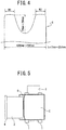
- FIG. 5 is a plan view illustrating a coil C of a general hot-rolled steel sheet S as mounted on an uncoiler.
- the wound hot-rolled steel sheet S has a nearly linear longitudinal end.
- a hot-rolled steel sheet S for a line pipe material is extremely thick, wide, and strong, and a heavy load is imposed on the coil opener 3 when the hot-rolled steel sheet S for a line pipe material wound around the coil C is unwound, as described earlier.
- the coil unwinding end of the hot-rolled steel sheet S for a line pipe material is formed with its widthwise center recessed inwards in the longitudinal direction with respect to its two widthwise ends, as illustrated in FIG. 2 .
- FIG. 4 illustrates details of the shape of the longitudinal end of the hot-rolled steel sheet S for a line pipe material.
- the hot-rolled steel sheet S for a line pipe material has specifications; Width: 1,200 mm to 2,300 mm; Thickness: 13 mm to 25.4 mm; and Strength: API Standard X65-grade or more.
- the hot-rolled steel sheet S is cut in unsteady portions at its longitudinal head and tail ends, that is, so-called crop portions in the cutting step, and is used in a state of being unwound after having been wound around the coil C.
- At least a longitudinal end corresponding to the start of unwinding is formed with a portion at its widthwise center recessed inwards in the longitudinal direction with respect to its two widthwise ends.
- the projection sizes of the two widthwise ends with respect to the recessed portion at the widthwise center are 20 mm to 295 mm, and the sum of the widths W1 and W2 of projecting portions at the two widthwise ends is 1/4 to 1/2 of the sheet width
- an unsteady portion of the longitudinal end of the steel sheet that is, a crop portion is shaped into a fish tail-shaped structure by rough rolling.
- the steel sheet is reduced in width by a width rolling mill in the rough rolling step and is then rolled by a horizontal rolling mill.
- a sizing press may be substituted for the width rolling mill.
- the fish tail-shaped crop portion is cut by a crop shear at a position 20 mm to 295 mm from the recess of the widthwise center. Since a crop shape meter which detects the shape of the crop portion is provided in the rough rolling step, the cut position of a crop shear need only be determined in accordance with the shape of the crop portion detected by the crop shape meter.
- the hot-rolled steel sheet S wound around the coil C is unwound by plastically deforming the hot-rolled steel sheet S.
- the load imposed on the rotating shaft 4 of the coil opener 3 is heaviest at the start of unwinding as the moment arm is longest. Therefore, forming a portion at the widthwise center recessed inwards in the longitudinal direction with respect to the two widthwise ends can reduce the cross-sectional area and, in turn, can reduce the load imposed on the rotating shaft 4 of the coil opener 3 during unwinding.
- the longitudinal end of the hot-rolled steel sheet may even be formed with its widthwise center projecting outwards in the longitudinal direction with respect to its two widthwise ends.
- the load concentrates on the rotating shaft 4 of the coil opener 3.
- the longitudinal end of the hot-rolled steel sheet S is formed with its widthwise center recessed with respect to its two widthwise ends, the load imposed on the rotating shaft 4 of the coil opener 3 can be distributed and prevented from exceeding its upper limit accordingly.
- the hot-rolled steel sheet S in this embodiment is cut in unsteady portions at its longitudinal head and tail ends in a cutting step after a rough rolling step, has a width of 1,200 mm to 2,300 mm, a thickness of 13 mm to 25.4 mm, and at least an API standard X65-grade strength, and is used in a state of being unwound after having been wound around the coil.
- At least a longitudinal end corresponding to the start of unwinding is formed with a portion at its widthwise center recessed inwards in the longitudinal direction with respect to its two widthwise ends, the projection sizes of the two widthwise ends with respect to the recessed portion at the widthwise center are set to 20 mm to 295 mm, and the sum of the widths W1 and W2 of projecting portions at the two widthwise ends is set to 1/4 to 1/2 of the sheet width.
- This can prevent even the coil C of a thick, wide, high-strength steel sheet from exceeding the allowable load of the coil opener 3 during unwinding of the hot-rolled steel sheet S. Further, the steel sheet can be stably unwound without any extensive equipment improvement such as reinforcement of the coil opener 3.
- the sheet When the above-mentioned projection sizes are smaller than 20 mm, the sheet may be cut over the entire width and the allowable load of the coil opener 3 may be exceeded during unwinding of the hot-rolled steel sheet S.
- these projection sizes are larger than 295 mm, the projecting portions at the two widthwise ends may wrinkle during unwinding and the front end cannot be satisfactorily removed.
- the sum of the widths W1 and W2 of the projecting portions at the two widthwise ends is set smaller than 1/4 of the sheet width, the projecting portions at the two widthwise ends may wrinkle during unwinding and the front end cannot be satisfactorily removed.
- the sheet When the sum of the widths W1 and W2 of the projecting portions at the two widthwise ends is set larger than 1/2 of the sheet width, the sheet may be cut over the entire width and the allowable load of the coil opener 3 may be exceeded during unwinding of the hot-rolled steel sheet S.
- a method for manufacturing a hot-rolled steel sheet according to the above-described embodiment will be described below.
- the steps of manufacturing a hot-rolled steel sheet are defined as the steps of manufacturing a steel strip from a slab and roughly classified into heating, rough rolling, finish rolling, cooling, and winding steps in the order of execution.
- the following description assumes the heating step side as the upstream side and the winding step side as the downstream side.
- a slab is heated to 1, 100°C to 1, 300°C in a heating furnace and extracted on a table for transportation to the subsequent steps.
- width reduction rolling and horizontal rolling are performed on the transported slab by a width rolling mill and a rough rolling mill each including at least a pair of rollers .
- the width rolling mill is provided on each or either of the upstream and downstream sides of the rough rolling mill. Width reduction rolling and horizontal rolling may be performed forwards to the downstream step side or backwards to the upstream step side. In the rough rolling step, further, when width reduction rolling and horizontal rolling may be performed only forwards or by at least two repetitions of forward and backward operations .
- the slab is formed into a sheet bar having a predetermined sheet width and thickness by the above-mentioned operations.
- a sizing press for reducing the width of the slab may be located upstream of the rough rolling mill.
- the sizing press is greater in efficiency of slab width reduction than the width rolling mill and is therefore used in considerably reducing the width of the slab.
- finish rolling step horizontal rolling is performed on the sheet bar using a finish rolling mill including at least one horizontal rolling mill including a pair of upper and lower rollers. Horizontal rolling is performed in one direction in this case.
- the transported steel sheet after finish rolling is cooled by spraying water onto it from the upper and lower positions.
- the cooled steel sheet is wound into a cylindrical shape by a coiler.
- the sheet bar means a steel sheet after the end of a rough rolling step and before finish rolling.
- the trailing end of the sheet bar in the transport direction is deformed into various forms by horizontal rolling and width reduction rolling in the rough rolling step and width reduction rolling by a sizing press to form crop portions.
- a tongue-shaped crop portion having a sheet widthwise center elongated in the rolling direction with respect to the sheet widthwise ends is available, as illustrated in FIG. 6B .
- a fish tail-shaped crop portion having sheet widthwise ends elongated in the rolling direction with respect to the sheet widthwise center, as illustrated in FIG. 6A is also available.
- Bilaterally asymmetrical crop portions may even be available, such as a bilaterally asymmetrical tongue-shaped crop portion as illustrated in FIG. 6C , and a bilaterally asymmetrical fish tail-shaped crop portion as illustrated in FIG. 6D .
- the crop portion on the trailing end of a sheet bar in the transport direction can be formed into a desired shape by adjusting the amount of width reduction by a width rolling mill and the amount of rolling by a horizontal rough rolling mill in a rough rolling step, the number of passes in the rough rolling step, and the amount of width reduction by a sizing press.
- the crop portion on the trailing end of the sheet bar in the transport direction is formed into a fish tail-shaped structure as illustrated in FIG. 6A , and the intermediate portion between the tips of projections and the bottom of a recess in the fish tail-shaped structure is cut, as illustrated in FIG. 7 .
- the crop portions on the leading and trailing ends of a sheet bar in the transport direction are cut on the entry side of a finish rolling mill. This cutting of the crop portions is done to stabilize threading during finish rolling.
- a crop shear for cutting the crop portions on the leading and trailing ends of a sheet bar in the transport direction is generally located on the entry side of a finish rolling mill, but it need only be located downstream of a rough rolling step and upstream of a finish rolling step, as long as the crop portions formed on the leading and trailing ends of a sheet bar in the transport direction in the rough rolling step can be cut.
- the maximum error X (mm) depends on the accuracy of tracking of the steel sheet and is generally 0 to 90 mm.
- the minimum length L (mm) from the bottom of the recess to the tips of the projections in the fish tail-shaped structure is set to (2X + 5) mm or more, and the upper limit of the minimum length L is set to 300 mm in terms of the product yield.
- shaping is performed so that the minimum length L (mm) from the bottom of the recess to the tips of the projections in the fish tail-shaped structure satisfies: 2 X + 5 ⁇ L ⁇ 300 for 0 ⁇ X ⁇ 90 where X is the maximum error (mm) of the cut position of the crop shear.
- the minimum length L is smaller than (2X + 5) mm, cutting the intermediate portion between the bottom of the recess and the tips of the projections in the fish tail-shaped structure as a target cut position may result in a cutting miss or full-width sheet cutting.
- the minimum length L is larger than 300 mm, the projecting portions at the two widthwise ends may wrinkle during unwinding and the front end cannot be removed.
- the target cut position is set at a position less than X mm from the bottom of a recess to the tips of projections in the fish tail-shaped structure, if the position where the blade of the crop shear actually comes into contact with the sheet bar deviates from the target cut position toward the bottom of the recess by X mm, full-width sheet cutting may occur, as illustrated in FIG. 8A . Therefore, the target cut position is preferably set more to the tips of the projections than a position X mm from the bottom of the recess to the tips of the projections in the fish tail-shaped structure.
- the target cut position is preferably set more to the bottom of the recess than a position (X + 5) mm from the tips of the projections to the bottom of the recess in the fish tail-shaped structure.
- the target cut position is preferably set between a position X mm from the bottom of the recess toward the tips of the projections in the fish tail-shaped structure and a position (X + 5) mm from the tips of the projections toward the bottom of the recess.
- FIG. 9 illustrates a preferable range of the intermediate portion between the bottom of the recess and the tips of the projections in the fish tail-shaped structure, in which the target cut position is set.
- a sheet bar having a thickness of 60 mm, a width of 1,500 mm, and a finish rolling mill entry-side temperature of 900°C was processed under various manufacturing conditions in a rough rolling step to form sheet bars having various planar shapes, the trailing ends of the sheet bars in the transport direction were cut by a crop shear in front of a finish rolling mill to form coils, and it was determined whether hot-rolled steel sheets wound around the coils could be unwound. In this case, the maximum error of the cut position of the crop shear was 90 mm. Table 1 represents unwinding results.
- each hot-rolled steel sheet (the coil tail end in the drawings) could be formed with its widthwise center recessed with respect to its two widthwise ends, and since the sum of the widths W1 and W2 of projecting portions at the two widthwise ends was set to 1/4 to 1/2 of the sheet width, unwinding could be performed while reducing the load imposed on the coil opener.
Landscapes
- Engineering & Computer Science (AREA)
- Mechanical Engineering (AREA)
- Metal Rolling (AREA)
- Winding, Rewinding, Material Storage Devices (AREA)
Abstract
Description
- The present invention relates to a hot-rolled steel sheet which is rolled by rough rolling and cut in unsteady portions at its longitudinal head and tail ends, and a method for manufacturing the same and, more particularly, to such technologies suitable for a thick, wide, high-strength hot-rolled steel sheet.
- Electric resistance welded steel pipes or spiral steel pipes made of hot-rolled steel sheets are used for pipelines which transport crude oil and natural gas. Hot-rolled steel sheets for line pipe materials of this type require high-strength, extremely thick specifications in terms of efficient transportation of, for example, crude oil and natural gas. Furthermore, since pipelines may be laid in seismic zones, the line pipe materials also need to be tough. Such hot-rolled steel sheets for line pipe materials need to satisfy, for example, X65-grade strength stipulated by API (American Petroleum Institute) standards, and examples of such hot-rolled steel sheets include a hot-rolled steel sheet disclosed in
PTL 1. A hot-rolled steel sheet for a line pipe material, as disclosed inPTL 1, is generally thick, wide, and strong. - PTL 1:
JP 2015-101781 A - A hot-rolled steel sheet for a line pipe material is once wound around a coil, which is then unwound to form a steel pipe. The coil of the hot-rolled steel sheet is unwound by a coil opener, but since such a hot-rolled steel sheet for a line pipe material is extremely thick, wide, and strong, the allowable load of the coil opener may be exceeded during this unwinding.
- The present invention has been made in consideration of the above-described problem, and has as its object to provide a hot-rolled steel sheet which does not exceed the allowable load of a coil opener during unwinding, even with a coil of a thick, wide, high-strength hot-rolled steel sheet, and a method for manufacturing the same.
- To solve the above-described problem, the inventors of the present invention conducted a close examination for a hot-rolled steel sheet which facilitates unwinding by a coil opener by shaping a crop portion formed on the trailing end of the steel sheet in the transport direction in a rough rolling step before finish rolling into a fish tail-shaped structure, and cutting the intermediate portion between the bottom of a recess and the tips of projections in the fish tail-shaped structure to form a recess at the widthwise center of the unwinding end of the hot-rolled steel sheet in the wound coil.
- A coil is generally unwound by picking up and bending the rearmost end of a hot-rolled steel sheet by a coil opener. In this case, when the hot-rolled steel sheet has a small width, the coil opener can easily cause pickup deformation and bending deformation. In a rough rolling step before finish rolling, a crop portion formed on the trailing end of the steel sheet in the transport direction can be shaped into a fish tail-shaped structure as illustrated in
FIG. 6A . Then, as illustrated inFIG. 7 , when the intermediate portion between the bottom of a recess and the tips of projections in the fish tail-shaped structure is cut by a crop shear, the trailing end of the hot-rolled steel sheet can be formed with its widthwise center recessed more than its two widthwise ends. - An error occurs between the target cut position and the position where the blade of the crop shear actually comes into contact with the steel sheet, and, therefore, depending on the cut position accuracy of the crop shear, swinging down the blade of the crop shear while aiming at the target cut position of the fish tail-shaped crop portion, may result in full-width sheet cutting or a cutting miss because of a failure of contact with the fish tail-shaped structure of the crop portion. Under the circumstances, the fish tail length is set large enough to cause neither full-width sheet cutting nor a cutting miss even when an error occurs between the target cut position and the actual cut position.
- Again, since an error occurs between the target cut position and the position where the blade of the crop shear actually comes into contact with the steel sheet, the target cut position needs to be set in consideration of the error. The target cut position needs to be set to allow the blade of the crop shear to be swung down with neither full-width sheet cutting nor a cutting miss even when the cut position of the crop shear deviates from the target cut position.
- The present invention has been made based on the above-mentioned finding and includes the following gist.
- To solve the above-described problem, the present invention in one aspect provides a hot-rolled steel sheet cut in unsteady portions at a longitudinal head end and a longitudinal tail end in cutting after rough rolling, having a width of 1,200 mm to 2,300 mm, a thickness of 13 mm to 25.4 mm, and at least an API standard X65-grade strength, and used in a state of being unwound after having been wound around a coil, wherein at least a longitudinal end corresponding to start of unwinding includes a portion at a widthwise center recessed inwards in a longitudinal direction with respect to two widthwise ends, projection sizes of the two widthwise ends with respect to the recessed portion at the widthwise center are 20 mm to 295 mm, and a sum of widths of projecting portions at the two widthwise ends is 1/4 to 1/2 of the width of the sheet.
- The present invention in another aspect provides a method for manufacturing a hot-rolled steel sheet, the method including: rough rolling; finish rolling; and winding, in which the steel sheet cut by a crop shear in a crop portion on a trailing end of the steel sheet in a transport direction after the rough rolling and before the finish rolling, finish-rolled in the finish rolling, and wound in the winding has a width of 1,200 mm to 2,300 mm, a thickness of 13 mm to 25.4 mm, and at least an API standard X65-grade strength, wherein in the rough rolling, the crop portion formed on the trailing end of the steel sheet in the transport direction is shaped into a fish tail-shaped structure by width reduction rolling using a width rolling mill and horizontal rolling using a horizontal rough rolling mill, and shaping is performed so that a minimum length L (mm) from a bottom of a recess to a tip of a projection in the fish tail-shaped structure satisfies:

where X is a maximum error (mm) of a cut position of the crop shear,
and an intermediate portion between the bottom of the recess and the tip of the projection is cut as a target cut position. - According to the present invention, even a coil of a thick, wide, high-strength steel sheet can be prevented from exceeding the allowable load of a coil opener during unwinding. Further, the steel sheet can be stably unwound without any extensive equipment improvement such as reinforcement of the coil opener.
-
-
FIG. 1 is a front view illustrating a hot-rolled steel sheet coil as mounted on an uncoiler, as one embodiment of a hot-rolled steel sheet according to the present invention; -
FIG. 2 is a plan view of the uncoiler illustrated inFIG. 1 ; -
FIGS. 3A to 3E illustrate views for explaining the start of unwinding by a coil opener; -
FIG. 4 is a diagram for explaining the shape of a longitudinal end corresponding to the start of unwinding of the hot-rolled steel sheet illustrated inFIG. 2 ; -
FIG. 5 is a plan view illustrating a general hot-rolled steel sheet coil as mounted on an uncoiler; -
FIGS. 6A to 6D illustrate schematic views of the planar shapes of crop portions formed on the leading and trailing ends of the steel sheet in the transport direction; -
FIG. 7 is a schematic view illustrating the cut position of the crop; -
FIGS. 8A to 8B illustrate schematic diagrams of the errors between the target cut positions and the positions where the blade of a cutter actually comes into contact with the steel sheet; and -
FIG. 9 is a schematic diagram illustrating the range in which the target cut position is set. - The following embodiments exemplify devices or methods for embodying the technical idea of the present invention, and the technical idea of the present invention does not limit, for example, the materials, shapes, structures, and arrangements of components to the following specific examples. Various changes can be made to the technical idea of the present invention within the technical scope defined by claims described in the scope of claims.
- A hot-rolled steel sheet according to an embodiment of the present invention will be described below with reference to the drawings.
FIG. 1 is a front view illustrating a hot-rolled steel sheet in this embodiment wrapped around a coil, as mounted on an uncoiler, andFIG. 2 is a plan view of the uncoiler illustrated inFIG. 1 . The uncoiler includescradle rollers 1 which support a coil C of a hot-rolled steel sheet S, apayoff reel 2 inserted into the coil C, and acoil opener 3 inserted at the unwinding end of the hot-rolled steel sheet S wound around the coil C. Thepayoff reel 2 and thecradle rollers 1 are rotated by motors (not illustrated) and the coil C of the hot-rolled steel sheet S thus can rotate. - The
coil opener 3 in this embodiment is made of a wide, tapered sheet material and has its proximal end supported by a rotatingshaft 4. Therefore, the distal end of thecoil opener 3 can be rotated by rotating the rotatingshaft 4. Thecoil opener 3 can be brought close to or moved away from the hot-rolled steel sheet coil C by a moving device (not illustrated). As will be described later, the hot-rolled steel sheet S can be unwound by catching the distal end of thecoil opener 3 on the unwinding end of the hot-rolled steel sheet S wound around the coil C, and in this state, rotating the coil C using thepayoff reel 2 and thecradle rollers 1. Thecoil opener 3 is in the so-called cantilevered state and has an upper limit in load imposed on the rotatingshaft 4. -
FIGS. 3A to 3E illustrate views for explaining the start of unwinding of the hot-rolled steel sheet coil C by an uncoiler. First, thecoil opener 3 is moved away and thepayoff reel 2 of the uncoiler is retracted, as illustrated inFIG. 3A , and the hot-rolled steel sheet coil C is mounted on thecradle rollers 1 in this state, as illustrated inFIG. 3B . Thepayoff reel 2 is then inserted into the hot-rolled steel sheet coil C, and thecoil opener 3 is brought close to the hot-rolled steel sheet coil C to catch its distal end on the unwinding end of the coil C, as illustrated inFIG. 3C . In this state, when the coil C is rotated by thepayoff reel 2 and thecradle rollers 1, as illustrated inFIG. 3D , the unwinding end of the coil C is unwound and the hot-rolled steel sheet S is pulled out, as illustrated inFIG. 3E . - In this uncoiler, the coils of various hot-rolled steel sheets S are unwound, including hot-rolled steel sheets S for line pipe materials.
FIG. 5 is a plan view illustrating a coil C of a general hot-rolled steel sheet S as mounted on an uncoiler. In the coil C of the general hot-rolled steel sheet S, the wound hot-rolled steel sheet S has a nearly linear longitudinal end. In contrast to this, a hot-rolled steel sheet S for a line pipe material is extremely thick, wide, and strong, and a heavy load is imposed on thecoil opener 3 when the hot-rolled steel sheet S for a line pipe material wound around the coil C is unwound, as described earlier. Hence, in this embodiment, the coil unwinding end of the hot-rolled steel sheet S for a line pipe material is formed with its widthwise center recessed inwards in the longitudinal direction with respect to its two widthwise ends, as illustrated inFIG. 2 . -
FIG. 4 illustrates details of the shape of the longitudinal end of the hot-rolled steel sheet S for a line pipe material. The hot-rolled steel sheet S for a line pipe material has specifications; Width: 1,200 mm to 2,300 mm; Thickness: 13 mm to 25.4 mm; and Strength: API Standard X65-grade or more. The hot-rolled steel sheet S is cut in unsteady portions at its longitudinal head and tail ends, that is, so-called crop portions in the cutting step, and is used in a state of being unwound after having been wound around the coil C. At least a longitudinal end corresponding to the start of unwinding is formed with a portion at its widthwise center recessed inwards in the longitudinal direction with respect to its two widthwise ends. The projection sizes of the two widthwise ends with respect to the recessed portion at the widthwise center are 20 mm to 295 mm, and the sum of the widths W1 and W2 of projecting portions at the two widthwise ends is 1/4 to 1/2 of the sheet width. - To form the longitudinal end of the hot-rolled steel sheet S with its widthwise center recessed inwards in the longitudinal direction with respect to its two widthwise ends in the above-mentioned manner, an unsteady portion of the longitudinal end of the steel sheet, that is, a crop portion is shaped into a fish tail-shaped structure by rough rolling. When the crop portion of the steel sheet is shaped into a fish tail-shaped structure, for example, the steel sheet is reduced in width by a width rolling mill in the rough rolling step and is then rolled by a horizontal rolling mill. A sizing press may be substituted for the width rolling mill. The fish tail-shaped crop portion is cut by a crop shear at a position 20 mm to 295 mm from the recess of the widthwise center. Since a crop shape meter which detects the shape of the crop portion is provided in the rough rolling step, the cut position of a crop shear need only be determined in accordance with the shape of the crop portion detected by the crop shape meter.
- The hot-rolled steel sheet S wound around the coil C is unwound by plastically deforming the hot-rolled steel sheet S. With this plastic deformation, when the sheet thickness is equal, the larger the sheet width, the larger the cross-sectional area, and the heavier the load imposed on the
rotating shaft 4 of thecoil opener 3. The load imposed on therotating shaft 4 of thecoil opener 3 is heaviest at the start of unwinding as the moment arm is longest. Therefore, forming a portion at the widthwise center recessed inwards in the longitudinal direction with respect to the two widthwise ends can reduce the cross-sectional area and, in turn, can reduce the load imposed on therotating shaft 4 of thecoil opener 3 during unwinding. When the cross-sectional area is equal, the longitudinal end of the hot-rolled steel sheet may even be formed with its widthwise center projecting outwards in the longitudinal direction with respect to its two widthwise ends. However, in such a shape, the load concentrates on therotating shaft 4 of thecoil opener 3. When the longitudinal end of the hot-rolled steel sheet S is formed with its widthwise center recessed with respect to its two widthwise ends, the load imposed on therotating shaft 4 of thecoil opener 3 can be distributed and prevented from exceeding its upper limit accordingly. - As described above, the hot-rolled steel sheet S in this embodiment is cut in unsteady portions at its longitudinal head and tail ends in a cutting step after a rough rolling step, has a width of 1,200 mm to 2,300 mm, a thickness of 13 mm to 25.4 mm, and at least an API standard X65-grade strength, and is used in a state of being unwound after having been wound around the coil. At least a longitudinal end corresponding to the start of unwinding is formed with a portion at its widthwise center recessed inwards in the longitudinal direction with respect to its two widthwise ends, the projection sizes of the two widthwise ends with respect to the recessed portion at the widthwise center are set to 20 mm to 295 mm, and the sum of the widths W1 and W2 of projecting portions at the two widthwise ends is set to 1/4 to 1/2 of the sheet width. This can prevent even the coil C of a thick, wide, high-strength steel sheet from exceeding the allowable load of the
coil opener 3 during unwinding of the hot-rolled steel sheet S. Further, the steel sheet can be stably unwound without any extensive equipment improvement such as reinforcement of thecoil opener 3. When the above-mentioned projection sizes are smaller than 20 mm, the sheet may be cut over the entire width and the allowable load of thecoil opener 3 may be exceeded during unwinding of the hot-rolled steel sheet S. When these projection sizes are larger than 295 mm, the projecting portions at the two widthwise ends may wrinkle during unwinding and the front end cannot be satisfactorily removed. When the sum of the widths W1 and W2 of the projecting portions at the two widthwise ends is set smaller than 1/4 of the sheet width, the projecting portions at the two widthwise ends may wrinkle during unwinding and the front end cannot be satisfactorily removed. When the sum of the widths W1 and W2 of the projecting portions at the two widthwise ends is set larger than 1/2 of the sheet width, the sheet may be cut over the entire width and the allowable load of thecoil opener 3 may be exceeded during unwinding of the hot-rolled steel sheet S. - A method for manufacturing a hot-rolled steel sheet according to the above-described embodiment will be described below. The steps of manufacturing a hot-rolled steel sheet are defined as the steps of manufacturing a steel strip from a slab and roughly classified into heating, rough rolling, finish rolling, cooling, and winding steps in the order of execution. The following description assumes the heating step side as the upstream side and the winding step side as the downstream side.
- In the heating step, a slab is heated to 1, 100°C to 1, 300°C in a heating furnace and extracted on a table for transportation to the subsequent steps.
- In the rough rolling step, width reduction rolling and horizontal rolling are performed on the transported slab by a width rolling mill and a rough rolling mill each including at least a pair of rollers . The width rolling mill is provided on each or either of the upstream and downstream sides of the rough rolling mill. Width reduction rolling and horizontal rolling may be performed forwards to the downstream step side or backwards to the upstream step side. In the rough rolling step, further, when width reduction rolling and horizontal rolling may be performed only forwards or by at least two repetitions of forward and backward operations . In the rough rolling step, the slab is formed into a sheet bar having a predetermined sheet width and thickness by the above-mentioned operations.
- In the rough rolling step, a sizing press for reducing the width of the slab may be located upstream of the rough rolling mill. The sizing press is greater in efficiency of slab width reduction than the width rolling mill and is therefore used in considerably reducing the width of the slab.
- In the finish rolling step, horizontal rolling is performed on the sheet bar using a finish rolling mill including at least one horizontal rolling mill including a pair of upper and lower rollers. Horizontal rolling is performed in one direction in this case.
- In the cooling step, the transported steel sheet after finish rolling is cooled by spraying water onto it from the upper and lower positions.
- In the winding step, the cooled steel sheet is wound into a cylindrical shape by a coiler.
- The sheet bar means a steel sheet after the end of a rough rolling step and before finish rolling. The trailing end of the sheet bar in the transport direction is deformed into various forms by horizontal rolling and width reduction rolling in the rough rolling step and width reduction rolling by a sizing press to form crop portions. For example, a tongue-shaped crop portion having a sheet widthwise center elongated in the rolling direction with respect to the sheet widthwise ends is available, as illustrated in
FIG. 6B . A fish tail-shaped crop portion having sheet widthwise ends elongated in the rolling direction with respect to the sheet widthwise center, as illustrated inFIG. 6A , is also available. Bilaterally asymmetrical crop portions may even be available, such as a bilaterally asymmetrical tongue-shaped crop portion as illustrated inFIG. 6C , and a bilaterally asymmetrical fish tail-shaped crop portion as illustrated inFIG. 6D . - The crop portion on the trailing end of a sheet bar in the transport direction can be formed into a desired shape by adjusting the amount of width reduction by a width rolling mill and the amount of rolling by a horizontal rough rolling mill in a rough rolling step, the number of passes in the rough rolling step, and the amount of width reduction by a sizing press. In the present invention, to form the trailing end of a hot-rolled steel sheet in the transport direction after crop portion cutting with its widthwise center recessed with respect to its two widthwise ends, the crop portion on the trailing end of the sheet bar in the transport direction is formed into a fish tail-shaped structure as illustrated in
FIG. 6A , and the intermediate portion between the tips of projections and the bottom of a recess in the fish tail-shaped structure is cut, as illustrated inFIG. 7 . - Generally, the crop portions on the leading and trailing ends of a sheet bar in the transport direction are cut on the entry side of a finish rolling mill. This cutting of the crop portions is done to stabilize threading during finish rolling. A crop shear for cutting the crop portions on the leading and trailing ends of a sheet bar in the transport direction is generally located on the entry side of a finish rolling mill, but it need only be located downstream of a rough rolling step and upstream of a finish rolling step, as long as the crop portions formed on the leading and trailing ends of a sheet bar in the transport direction in the rough rolling step can be cut. Although the schemes of cutting by crop shears are commonly roughly classified into three types: the guillotine, crank, and drum types, but any cutting scheme may be used as long as the crop portion on the trailing ends of a sheet bar in the transport direction can be cut in the widthwise direction.
- When the sheet bar is cut by a crop shear, an error occurs between the target cut position and the position where the blade of the crop shear actually comes into contact with the sheet bar, and the maximum error X (mm) depends on the accuracy of tracking of the steel sheet and is generally 0 to 90 mm. In view of this, to reliably cut the intermediate portion between the bottom of a recess and the tips of projections in the fish tail-shaped structure of the crop portion formed on the trailing end of the sheet bar in the transport direction, the minimum length L (mm) from the bottom of the recess to the tips of the projections in the fish tail-shaped structure is set to (2X + 5) mm or more, and the upper limit of the minimum length L is set to 300 mm in terms of the product yield. In other words, shaping is performed so that the minimum length L (mm) from the bottom of the recess to the tips of the projections in the fish tail-shaped structure satisfies:

where X is the maximum error (mm) of the cut position of the crop shear. - When the minimum length L is smaller than (2X + 5) mm, cutting the intermediate portion between the bottom of the recess and the tips of the projections in the fish tail-shaped structure as a target cut position may result in a cutting miss or full-width sheet cutting. When the minimum length L is larger than 300 mm, the projecting portions at the two widthwise ends may wrinkle during unwinding and the front end cannot be removed.
- As described earlier, when the sheet bar is cut by a crop shear, an error occurs between the target cut position of the sheet bar and the position where the blade of the crop shear actually comes into contact with the sheet bar, and the maximum error X depends on the accuracy of tracking of the sheet bar and is generally 0 to 90 mm. When the target cut position is set at a position less than X mm from the bottom of a recess to the tips of projections in the fish tail-shaped structure, if the position where the blade of the crop shear actually comes into contact with the sheet bar deviates from the target cut position toward the bottom of the recess by X mm, full-width sheet cutting may occur, as illustrated in
FIG. 8A . Therefore, the target cut position is preferably set more to the tips of the projections than a position X mm from the bottom of the recess to the tips of the projections in the fish tail-shaped structure. - When the distance between the target cut position and the tips of the projections in the fish tail-shaped structure is (X + 5) mm or less, as illustrated in
FIG. 8B , if the position where the blade of the crop shear actually comes into contact with the sheet bar deviates from the target cut position toward the tips of the projections by X mm, a cutting miss may occur. Therefore, upon setting of a margin of 5 mm to prevent any cutting miss, the target cut position is preferably set more to the bottom of the recess than a position (X + 5) mm from the tips of the projections to the bottom of the recess in the fish tail-shaped structure. - From the foregoing description, to cut the intermediate portion between the bottom of a recess and the tips of projections in the fish tail-shaped structure of the crop portion formed on the sheet bar, with neither full-width sheet cutting nor a cutting miss, the target cut position is preferably set between a position X mm from the bottom of the recess toward the tips of the projections in the fish tail-shaped structure and a position (X + 5) mm from the tips of the projections toward the bottom of the recess.
FIG. 9 illustrates a preferable range of the intermediate portion between the bottom of the recess and the tips of the projections in the fish tail-shaped structure, in which the target cut position is set. When the target cut position is set in the above-mentioned manner, even if the error between the target cut position and the position where the blade of the crop shear actually comes into contact with the sheet bar reaches the maximum error X (mm), cutting can be performed with neither full-width sheet cutting nor a cutting miss. - To manufacture a hot-rolled steel sheet for a line pipe material having a thickness of 25 mm, a width of 1,500 mm, and at least an API standard X65-grade strength, a sheet bar having a thickness of 60 mm, a width of 1,500 mm, and a finish rolling mill entry-side temperature of 900°C was processed under various manufacturing conditions in a rough rolling step to form sheet bars having various planar shapes, the trailing ends of the sheet bars in the transport direction were cut by a crop shear in front of a finish rolling mill to form coils, and it was determined whether hot-rolled steel sheets wound around the coils could be unwound. In this case, the maximum error of the cut position of the crop shear was 90 mm. Table 1 represents unwinding results. For Nos. 1 and 2 in Table 1, since the length L from the bottom of a recess to the tips of projections in a fish tail-shaped structure ("Projection Size" in Table 1) is small, each sheet was cut over the entire width, as in the conventional technologies. Therefore, the load imposed on a coil opener was too heavy to allow unwinding. For Nos. 3 to 5 in Table 1, since the length L from the bottom of a recess to the tips of projections in a fish tail-shaped structure is large, and cutting was performed in consideration of the error of the cut position, the trailing end of each hot-rolled steel sheet (the coil tail end in the drawings) could be formed with its widthwise center recessed with respect to its two widthwise ends, and since the sum of the widths W1 and W2 of projecting portions at the two widthwise ends was set to 1/4 to 1/2 of the sheet width, unwinding could be performed while reducing the load imposed on the coil opener.
- For No. 6, since the length L from the bottom of a recess to the tips of projections in a fish tail-shaped structure is small, and the sheet was cut at a position close to the bottom of the recess, the trailing end of the hot-rolled steel sheet could be formed with its widthwise center recessed with respect to its two widthwise ends, but since the sum of the widths W1 and W2 of projecting portions at the two widthwise ends is larger than 1/2 of the sheet width, the load imposed on the coil opener could not be sufficiently reduced, resulting in a failure of unwinding.
- For No. 7, since the length L from the bottom of a recess to the tips of projections in a fish tail-shaped structure is small, and the sheet was cut at a position close to the tips of the projections, the trailing end of the hot-rolled steel sheet could be formed with its widthwise center recessed with respect to its two widthwise ends, but since the sum of the widths W1 and W2 of projecting portions at the two widthwise ends is smaller than 1/4 of the sheet width, the front end of the coil wrinkled during unwinding by the coil opener, resulting in a failure of unwinding.
[Table 1] Steel Sheet Projection Size from Bottom of Recess Shape of Coil Tail End W1 W2 Unwinding Note No. [mm] [mm] [mm] 1 10 Rectangle - - × Comparative Example 2 50 Rectangle - - × Comparative Example 3 100 Recessed at Widthwise Center 300 400 ○ Inventive Example 4 200 Recessed at Widthwise Center 250 300 ○ Inventive Example 5 290 Recessed at Widthwise Center 200 200 ○ Inventive Example 6 75 Recessed at Widthwise Center 400 450 × Comparative Example 7 300 Recessed at Widthwise Center 150 200 × Comparative Example - The present invention encompasses various embodiments and the like which are not described herein, as a matter of course. Accordingly, the technical scope of the present invention is defined only by specific matters of the invention described in the scope of claims appropriate from the foregoing description.
-
- 1
- cradle roller
- 2
- payoff reel
- 3
- coil opener
- 4
- rotating shaft
- C
- coil
- S
- steel sheet
Claims (3)
- A hot-rolled steel sheet cut in unsteady portions at a longitudinal head end and a longitudinal tail end in cutting after rough rolling, having a width of 1,200 mm to 2,300 mm, a thickness of 13 mm to 25.4 mm, and at least an API standard X65-grade strength, and used in a state of being unwound after having been wound around a coil, , wherein at least a longitudinal end corresponding to start of unwinding includes a portion at a widthwise center recessed inwards in a longitudinal direction with respect to two widthwise ends, projection sizes of the two widthwise ends with respect to the recessed portion at the widthwise center are 20 mm to 295 mm, and a sum of widths of projecting portions at the two widthwise ends is 1/4 to 1/2 of the width of the sheet.
- A method for manufacturing a hot-rolled steel sheet, the method comprising: rough rolling; finish rolling; and winding, in which the steel sheet cut by a crop shear in a crop portion on a trailing end of the steel sheet in a transport direction after the rough rolling and before the finish rolling, finish-rolled in the finish rolling, and wound in the winding has a width of 1,200 mm to 2,300 mm, a thickness of 13 mm to 25.4 mm, and at least an API standard X65-grade strength, wherein in the rough rolling, the crop portion formed on the trailing end of the steel sheet in the transport direction is shaped into a fish tail-shaped structure by width reduction rolling using a width rolling mill and horizontal rolling using a horizontal rough rolling mill, and shaping is performed so that a minimum length L (mm) from a bottom of a recess to a tip of a projection in the fish tail-shaped structure satisfies:

where X is a maximum error (mm) of a cut position of the crop shear,
and an intermediate portion between the bottom of the recess and the tip of the projection is cut as a target cut position. - The method for manufacturing a hot-rolled steel sheet according to claim 2, wherein the target cut position is set between a position X mm from the bottom of the recess toward the tip of the projection in the fish tail-shaped structure and a position (X + 5) mm from the tip of the projection toward the bottom of the recess.
Priority Applications (1)
| Application Number | Priority Date | Filing Date | Title |
|---|---|---|---|
| PL16868476T PL3381577T3 (en) | 2015-11-25 | 2016-11-18 | Hot-rolled steel sheet and method for manufacturing same |
Applications Claiming Priority (2)
| Application Number | Priority Date | Filing Date | Title |
|---|---|---|---|
| JP2015229755 | 2015-11-25 | ||
| PCT/JP2016/084269 WO2017090528A1 (en) | 2015-11-25 | 2016-11-18 | Hot-rolled steel sheet and method for manufacturing same |
Publications (3)
| Publication Number | Publication Date |
|---|---|
| EP3381577A1 true EP3381577A1 (en) | 2018-10-03 |
| EP3381577A4 EP3381577A4 (en) | 2018-12-26 |
| EP3381577B1 EP3381577B1 (en) | 2020-01-08 |
Family
ID=58763464
Family Applications (1)
| Application Number | Title | Priority Date | Filing Date |
|---|---|---|---|
| EP16868476.9A Active EP3381577B1 (en) | 2015-11-25 | 2016-11-18 | Hot-rolled steel sheet and method for manufacturing same |
Country Status (8)
| Country | Link |
|---|---|
| US (1) | US11241726B2 (en) |
| EP (1) | EP3381577B1 (en) |
| JP (1) | JP6562084B2 (en) |
| KR (1) | KR102089194B1 (en) |
| CN (1) | CN108290192B (en) |
| PL (1) | PL3381577T3 (en) |
| TW (1) | TWI628008B (en) |
| WO (1) | WO2017090528A1 (en) |
Families Citing this family (2)
| Publication number | Priority date | Publication date | Assignee | Title |
|---|---|---|---|---|
| DE102019126403B4 (en) * | 2019-09-30 | 2023-03-23 | Trumpf Werkzeugmaschinen Gmbh + Co. Kg | Method for loading a sheet storage device of a flatbed machine tool and flatbed machine tool |
| CN119839046B (en) * | 2025-02-07 | 2025-10-28 | 鞍钢股份有限公司 | Unmanned end cutting method and device for wire separating and winding unit |
Family Cites Families (15)
| Publication number | Priority date | Publication date | Assignee | Title |
|---|---|---|---|---|
| DE3151384A1 (en) * | 1981-12-24 | 1983-07-07 | Thyssen AG vorm. August Thyssen-Hütte, 4100 Duisburg | METHOD FOR MEASURING THE WIDTH, IN PARTICULAR OF THE HEAD, OF SELF-LUMINOUS ROLLING MATERIAL AND METHOD FOR SCOOPING THE HEAD OF SELF-LUMINOUS ROLLING MATERIAL |
| JPS59174209A (en) | 1983-03-25 | 1984-10-02 | Hitachi Ltd | Reversible rolling mill control device |
| JPS59176864A (en) * | 1983-03-28 | 1984-10-06 | Toshiba Corp | Composite electronic computer device |
| JPS62173115A (en) | 1986-01-23 | 1987-07-30 | Nippon Steel Corp | Control method for cutting of shot rolled crop |
| JPH09225527A (en) | 1996-02-19 | 1997-09-02 | Kawasaki Steel Corp | Rolling coil tail end unwinding method and device |
| JP3329251B2 (en) * | 1998-01-16 | 2002-09-30 | 日本鋼管株式会社 | Manufacturing method of hot rolled steel sheet |
| JP5223379B2 (en) * | 2007-03-08 | 2013-06-26 | 新日鐵住金株式会社 | High strength hot rolled steel sheet for spiral pipe with excellent low temperature toughness and method for producing the same |
| JP5353260B2 (en) * | 2009-01-19 | 2013-11-27 | Jfeスチール株式会社 | Winding equipment and winding method for high-strength thick hot-rolled steel sheet |
| CN101845596B (en) | 2009-03-24 | 2012-12-19 | 宝山钢铁股份有限公司 | Wide thick plate for X80 pipe line steel and manufacturing method thereof |
| JP5857989B2 (en) | 2013-03-14 | 2016-02-10 | Jfeスチール株式会社 | Manufacturing method of hot-rolled steel sheet |
| JP5884753B2 (en) * | 2013-03-15 | 2016-03-15 | Jfeスチール株式会社 | Manufacturing method of hot-rolled steel sheet |
| JP5783229B2 (en) * | 2013-11-28 | 2015-09-24 | Jfeスチール株式会社 | Hot-rolled steel sheet and manufacturing method thereof |
| WO2015182051A1 (en) | 2014-05-30 | 2015-12-03 | Jfeスチール株式会社 | Method for manufacturing hot-rolled steel sheet, steel sheet cutting location setting device, steel sheet cutting location setting method, and steel sheet manufacturing method |
| US10730088B2 (en) | 2014-05-30 | 2020-08-04 | Jfe Steel Corporation | Method for manufacturing hot-rolled steel sheet, steel sheet cutting location setting device, steel sheet cutting location setting method, and steel sheet manufacturing method |
| JP6789871B2 (en) * | 2017-03-31 | 2020-11-25 | 株式会社荏原製作所 | A program that executes a method for controlling the display related to the operation of the semiconductor manufacturing device, a system that displays the method and the display related to the operation of the semiconductor manufacturing device. |
-
2016
- 2016-11-18 KR KR1020187011468A patent/KR102089194B1/en active Active
- 2016-11-18 CN CN201680069876.9A patent/CN108290192B/en active Active
- 2016-11-18 JP JP2017552390A patent/JP6562084B2/en active Active
- 2016-11-18 EP EP16868476.9A patent/EP3381577B1/en active Active
- 2016-11-18 WO PCT/JP2016/084269 patent/WO2017090528A1/en not_active Ceased
- 2016-11-18 US US15/765,557 patent/US11241726B2/en active Active
- 2016-11-18 PL PL16868476T patent/PL3381577T3/en unknown
- 2016-11-24 TW TW105138532A patent/TWI628008B/en active
Also Published As
| Publication number | Publication date |
|---|---|
| WO2017090528A1 (en) | 2017-06-01 |
| PL3381577T3 (en) | 2020-06-15 |
| US11241726B2 (en) | 2022-02-08 |
| CN108290192B (en) | 2023-11-10 |
| US20190076896A1 (en) | 2019-03-14 |
| EP3381577A4 (en) | 2018-12-26 |
| CN108290192A (en) | 2018-07-17 |
| TWI628008B (en) | 2018-07-01 |
| JP6562084B2 (en) | 2019-08-21 |
| JPWO2017090528A1 (en) | 2018-08-02 |
| EP3381577B1 (en) | 2020-01-08 |
| TW201718120A (en) | 2017-06-01 |
| KR20180059496A (en) | 2018-06-04 |
| KR102089194B1 (en) | 2020-03-13 |
Similar Documents
| Publication | Publication Date | Title |
|---|---|---|
| CN101553326B (en) | Cold rolled material production equipment and cold rolling method | |
| KR102382821B1 (en) | Steel plate slitting and cutting machine | |
| EP2937156A1 (en) | Shape-correcting and rolling method and shape-correcting device for high-strength steel | |
| JP6172108B2 (en) | Hot rolled steel sheet rolling method | |
| EP3381577B1 (en) | Hot-rolled steel sheet and method for manufacturing same | |
| JP6137109B2 (en) | Rough rolling method for hot-rolled steel sheet | |
| JP5353260B2 (en) | Winding equipment and winding method for high-strength thick hot-rolled steel sheet | |
| WO1998031482A1 (en) | Method and apparatus for rolling strip or plate | |
| JP5861791B2 (en) | Manufacturing method of hot-rolled steel sheet | |
| CN203665088U (en) | Rewinding unit | |
| JP7126076B2 (en) | Cold-rolled steel strip manufacturing facility and cold-rolled steel strip manufacturing method | |
| US20080230586A1 (en) | Method of Manufacturing Electric Resistance Welding Pipes Having Excellent Characterization of Welded Seams | |
| EP4306230A1 (en) | Method for manufacturing cold-rolled steel sheet, and manufacturing facility | |
| CN103998153B (en) | Strip metal plate | |
| JPH10263610A (en) | Continuous hot rolling of steel sheet | |
| JP6269548B2 (en) | Manufacturing method of hot-rolled steel sheet | |
| JP3766561B2 (en) | Coil box steel sheet winding stop control method | |
| TWI797912B (en) | Manufacturing method and manufacturing equipment of cold-rolled steel sheet | |
| JP3705226B2 (en) | Cold rolled steel sheet manufacturing method | |
| JP2009050887A (en) | Hot-rolled metal strip winding method and hot-rolled metal strip manufacturing method using the same | |
| CN107502731B (en) | Stainless steel wide and thick plate coil thermal annealing and pickling method | |
| JP2010264493A (en) | Winding device and winding method for high strength thick hot rolled steel sheet | |
| DE102006036223B3 (en) | Production line for producing a thin magnesium strip comprises a coiler having a coiling sleeve fixed coaxially to the rotary axis of a coiler mandrel | |
| JP5401926B2 (en) | Slab width reduction mold and slab width reduction method using the same | |
| JP2015104749A (en) | Winding device and winding method |
Legal Events
| Date | Code | Title | Description |
|---|---|---|---|
| STAA | Information on the status of an ep patent application or granted ep patent |
Free format text: STATUS: THE INTERNATIONAL PUBLICATION HAS BEEN MADE |
|
| PUAI | Public reference made under article 153(3) epc to a published international application that has entered the european phase |
Free format text: ORIGINAL CODE: 0009012 |
|
| STAA | Information on the status of an ep patent application or granted ep patent |
Free format text: STATUS: REQUEST FOR EXAMINATION WAS MADE |
|
| 17P | Request for examination filed |
Effective date: 20180419 |
|
| AK | Designated contracting states |
Kind code of ref document: A1 Designated state(s): AL AT BE BG CH CY CZ DE DK EE ES FI FR GB GR HR HU IE IS IT LI LT LU LV MC MK MT NL NO PL PT RO RS SE SI SK SM TR |
|
| AX | Request for extension of the european patent |
Extension state: BA ME |
|
| A4 | Supplementary search report drawn up and despatched |
Effective date: 20181126 |
|
| RIC1 | Information provided on ipc code assigned before grant |
Ipc: B21B 1/22 20060101ALN20181120BHEP Ipc: B21B 37/72 20060101ALI20181120BHEP Ipc: B21C 47/18 20060101AFI20181120BHEP Ipc: B21B 1/26 20060101ALI20181120BHEP Ipc: B21B 15/00 20060101ALI20181120BHEP |
|
| DAV | Request for validation of the european patent (deleted) | ||
| DAX | Request for extension of the european patent (deleted) | ||
| GRAP | Despatch of communication of intention to grant a patent |
Free format text: ORIGINAL CODE: EPIDOSNIGR1 |
|
| STAA | Information on the status of an ep patent application or granted ep patent |
Free format text: STATUS: GRANT OF PATENT IS INTENDED |
|
| RIC1 | Information provided on ipc code assigned before grant |
Ipc: B21B 1/26 20060101ALI20190628BHEP Ipc: B21B 37/72 20060101ALI20190628BHEP Ipc: B21B 15/00 20060101ALI20190628BHEP Ipc: B21B 1/22 20060101ALN20190628BHEP Ipc: B21C 47/18 20060101AFI20190628BHEP |
|
| INTG | Intention to grant announced |
Effective date: 20190730 |
|
| GRAS | Grant fee paid |
Free format text: ORIGINAL CODE: EPIDOSNIGR3 |
|
| GRAA | (expected) grant |
Free format text: ORIGINAL CODE: 0009210 |
|
| STAA | Information on the status of an ep patent application or granted ep patent |
Free format text: STATUS: THE PATENT HAS BEEN GRANTED |
|
| AK | Designated contracting states |
Kind code of ref document: B1 Designated state(s): AL AT BE BG CH CY CZ DE DK EE ES FI FR GB GR HR HU IE IS IT LI LT LU LV MC MK MT NL NO PL PT RO RS SE SI SK SM TR |
|
| REG | Reference to a national code |
Ref country code: GB Ref legal event code: FG4D |
|
| REG | Reference to a national code |
Ref country code: CH Ref legal event code: EP |
|
| REG | Reference to a national code |
Ref country code: DE Ref legal event code: R096 Ref document number: 602016028112 Country of ref document: DE |
|
| REG | Reference to a national code |
Ref country code: IE Ref legal event code: FG4D |
|
| REG | Reference to a national code |
Ref country code: AT Ref legal event code: REF Ref document number: 1222055 Country of ref document: AT Kind code of ref document: T Effective date: 20200215 |
|
| REG | Reference to a national code |
Ref country code: NL Ref legal event code: MP Effective date: 20200108 |
|
| REG | Reference to a national code |
Ref country code: LT Ref legal event code: MG4D |
|
| PG25 | Lapsed in a contracting state [announced via postgrant information from national office to epo] |
Ref country code: PT Free format text: LAPSE BECAUSE OF FAILURE TO SUBMIT A TRANSLATION OF THE DESCRIPTION OR TO PAY THE FEE WITHIN THE PRESCRIBED TIME-LIMIT Effective date: 20200531 Ref country code: NO Free format text: LAPSE BECAUSE OF FAILURE TO SUBMIT A TRANSLATION OF THE DESCRIPTION OR TO PAY THE FEE WITHIN THE PRESCRIBED TIME-LIMIT Effective date: 20200408 Ref country code: FI Free format text: LAPSE BECAUSE OF FAILURE TO SUBMIT A TRANSLATION OF THE DESCRIPTION OR TO PAY THE FEE WITHIN THE PRESCRIBED TIME-LIMIT Effective date: 20200108 Ref country code: RS Free format text: LAPSE BECAUSE OF FAILURE TO SUBMIT A TRANSLATION OF THE DESCRIPTION OR TO PAY THE FEE WITHIN THE PRESCRIBED TIME-LIMIT Effective date: 20200108 Ref country code: LT Free format text: LAPSE BECAUSE OF FAILURE TO SUBMIT A TRANSLATION OF THE DESCRIPTION OR TO PAY THE FEE WITHIN THE PRESCRIBED TIME-LIMIT Effective date: 20200108 Ref country code: NL Free format text: LAPSE BECAUSE OF FAILURE TO SUBMIT A TRANSLATION OF THE DESCRIPTION OR TO PAY THE FEE WITHIN THE PRESCRIBED TIME-LIMIT Effective date: 20200108 |
|
| PG25 | Lapsed in a contracting state [announced via postgrant information from national office to epo] |
Ref country code: IS Free format text: LAPSE BECAUSE OF FAILURE TO SUBMIT A TRANSLATION OF THE DESCRIPTION OR TO PAY THE FEE WITHIN THE PRESCRIBED TIME-LIMIT Effective date: 20200508 Ref country code: BG Free format text: LAPSE BECAUSE OF FAILURE TO SUBMIT A TRANSLATION OF THE DESCRIPTION OR TO PAY THE FEE WITHIN THE PRESCRIBED TIME-LIMIT Effective date: 20200408 Ref country code: GR Free format text: LAPSE BECAUSE OF FAILURE TO SUBMIT A TRANSLATION OF THE DESCRIPTION OR TO PAY THE FEE WITHIN THE PRESCRIBED TIME-LIMIT Effective date: 20200409 Ref country code: LV Free format text: LAPSE BECAUSE OF FAILURE TO SUBMIT A TRANSLATION OF THE DESCRIPTION OR TO PAY THE FEE WITHIN THE PRESCRIBED TIME-LIMIT Effective date: 20200108 Ref country code: SE Free format text: LAPSE BECAUSE OF FAILURE TO SUBMIT A TRANSLATION OF THE DESCRIPTION OR TO PAY THE FEE WITHIN THE PRESCRIBED TIME-LIMIT Effective date: 20200108 Ref country code: HR Free format text: LAPSE BECAUSE OF FAILURE TO SUBMIT A TRANSLATION OF THE DESCRIPTION OR TO PAY THE FEE WITHIN THE PRESCRIBED TIME-LIMIT Effective date: 20200108 |
|
| REG | Reference to a national code |
Ref country code: DE Ref legal event code: R097 Ref document number: 602016028112 Country of ref document: DE |
|
| PG25 | Lapsed in a contracting state [announced via postgrant information from national office to epo] |
Ref country code: DK Free format text: LAPSE BECAUSE OF FAILURE TO SUBMIT A TRANSLATION OF THE DESCRIPTION OR TO PAY THE FEE WITHIN THE PRESCRIBED TIME-LIMIT Effective date: 20200108 Ref country code: ES Free format text: LAPSE BECAUSE OF FAILURE TO SUBMIT A TRANSLATION OF THE DESCRIPTION OR TO PAY THE FEE WITHIN THE PRESCRIBED TIME-LIMIT Effective date: 20200108 Ref country code: RO Free format text: LAPSE BECAUSE OF FAILURE TO SUBMIT A TRANSLATION OF THE DESCRIPTION OR TO PAY THE FEE WITHIN THE PRESCRIBED TIME-LIMIT Effective date: 20200108 Ref country code: SK Free format text: LAPSE BECAUSE OF FAILURE TO SUBMIT A TRANSLATION OF THE DESCRIPTION OR TO PAY THE FEE WITHIN THE PRESCRIBED TIME-LIMIT Effective date: 20200108 Ref country code: CZ Free format text: LAPSE BECAUSE OF FAILURE TO SUBMIT A TRANSLATION OF THE DESCRIPTION OR TO PAY THE FEE WITHIN THE PRESCRIBED TIME-LIMIT Effective date: 20200108 Ref country code: SM Free format text: LAPSE BECAUSE OF FAILURE TO SUBMIT A TRANSLATION OF THE DESCRIPTION OR TO PAY THE FEE WITHIN THE PRESCRIBED TIME-LIMIT Effective date: 20200108 Ref country code: EE Free format text: LAPSE BECAUSE OF FAILURE TO SUBMIT A TRANSLATION OF THE DESCRIPTION OR TO PAY THE FEE WITHIN THE PRESCRIBED TIME-LIMIT Effective date: 20200108 |
|
| PLBE | No opposition filed within time limit |
Free format text: ORIGINAL CODE: 0009261 |
|
| STAA | Information on the status of an ep patent application or granted ep patent |
Free format text: STATUS: NO OPPOSITION FILED WITHIN TIME LIMIT |
|
| REG | Reference to a national code |
Ref country code: AT Ref legal event code: MK05 Ref document number: 1222055 Country of ref document: AT Kind code of ref document: T Effective date: 20200108 |
|
| 26N | No opposition filed |
Effective date: 20201009 |
|
| REG | Reference to a national code |
Ref country code: DE Ref legal event code: R082 Ref document number: 602016028112 Country of ref document: DE Representative=s name: HL KEMPNER PATENTANWAELTE, SOLICITORS (ENGLAND, DE Ref country code: DE Ref legal event code: R082 Ref document number: 602016028112 Country of ref document: DE Representative=s name: HL KEMPNER PATENTANWALT, RECHTSANWALT, SOLICIT, DE Ref country code: DE Ref legal event code: R082 Ref document number: 602016028112 Country of ref document: DE Representative=s name: HL KEMPNER PARTG MBB, DE |
|
| PG25 | Lapsed in a contracting state [announced via postgrant information from national office to epo] |
Ref country code: IT Free format text: LAPSE BECAUSE OF FAILURE TO SUBMIT A TRANSLATION OF THE DESCRIPTION OR TO PAY THE FEE WITHIN THE PRESCRIBED TIME-LIMIT Effective date: 20200108 Ref country code: AT Free format text: LAPSE BECAUSE OF FAILURE TO SUBMIT A TRANSLATION OF THE DESCRIPTION OR TO PAY THE FEE WITHIN THE PRESCRIBED TIME-LIMIT Effective date: 20200108 |
|
| PG25 | Lapsed in a contracting state [announced via postgrant information from national office to epo] |
Ref country code: SI Free format text: LAPSE BECAUSE OF FAILURE TO SUBMIT A TRANSLATION OF THE DESCRIPTION OR TO PAY THE FEE WITHIN THE PRESCRIBED TIME-LIMIT Effective date: 20200108 |
|
| PG25 | Lapsed in a contracting state [announced via postgrant information from national office to epo] |
Ref country code: MC Free format text: LAPSE BECAUSE OF FAILURE TO SUBMIT A TRANSLATION OF THE DESCRIPTION OR TO PAY THE FEE WITHIN THE PRESCRIBED TIME-LIMIT Effective date: 20200108 |
|
| REG | Reference to a national code |
Ref country code: CH Ref legal event code: PL |
|
| GBPC | Gb: european patent ceased through non-payment of renewal fee |
Effective date: 20201118 |
|
| PG25 | Lapsed in a contracting state [announced via postgrant information from national office to epo] |
Ref country code: LU Free format text: LAPSE BECAUSE OF NON-PAYMENT OF DUE FEES Effective date: 20201118 |
|
| REG | Reference to a national code |
Ref country code: BE Ref legal event code: MM Effective date: 20201130 |
|
| PG25 | Lapsed in a contracting state [announced via postgrant information from national office to epo] |
Ref country code: LI Free format text: LAPSE BECAUSE OF NON-PAYMENT OF DUE FEES Effective date: 20201130 Ref country code: CH Free format text: LAPSE BECAUSE OF NON-PAYMENT OF DUE FEES Effective date: 20201130 |
|
| PG25 | Lapsed in a contracting state [announced via postgrant information from national office to epo] |
Ref country code: FR Free format text: LAPSE BECAUSE OF NON-PAYMENT OF DUE FEES Effective date: 20201130 Ref country code: IE Free format text: LAPSE BECAUSE OF NON-PAYMENT OF DUE FEES Effective date: 20201118 |
|
| PG25 | Lapsed in a contracting state [announced via postgrant information from national office to epo] |
Ref country code: GB Free format text: LAPSE BECAUSE OF NON-PAYMENT OF DUE FEES Effective date: 20201118 |
|
| PG25 | Lapsed in a contracting state [announced via postgrant information from national office to epo] |
Ref country code: MT Free format text: LAPSE BECAUSE OF FAILURE TO SUBMIT A TRANSLATION OF THE DESCRIPTION OR TO PAY THE FEE WITHIN THE PRESCRIBED TIME-LIMIT Effective date: 20200108 Ref country code: CY Free format text: LAPSE BECAUSE OF FAILURE TO SUBMIT A TRANSLATION OF THE DESCRIPTION OR TO PAY THE FEE WITHIN THE PRESCRIBED TIME-LIMIT Effective date: 20200108 |
|
| PG25 | Lapsed in a contracting state [announced via postgrant information from national office to epo] |
Ref country code: MK Free format text: LAPSE BECAUSE OF FAILURE TO SUBMIT A TRANSLATION OF THE DESCRIPTION OR TO PAY THE FEE WITHIN THE PRESCRIBED TIME-LIMIT Effective date: 20200108 Ref country code: AL Free format text: LAPSE BECAUSE OF FAILURE TO SUBMIT A TRANSLATION OF THE DESCRIPTION OR TO PAY THE FEE WITHIN THE PRESCRIBED TIME-LIMIT Effective date: 20200108 |
|
| PG25 | Lapsed in a contracting state [announced via postgrant information from national office to epo] |
Ref country code: BE Free format text: LAPSE BECAUSE OF NON-PAYMENT OF DUE FEES Effective date: 20201130 |
|
| PGFP | Annual fee paid to national office [announced via postgrant information from national office to epo] |
Ref country code: DE Payment date: 20250930 Year of fee payment: 10 |
|
| PGFP | Annual fee paid to national office [announced via postgrant information from national office to epo] |
Ref country code: TR Payment date: 20251106 Year of fee payment: 10 |
|
| PGFP | Annual fee paid to national office [announced via postgrant information from national office to epo] |
Ref country code: PL Payment date: 20251014 Year of fee payment: 10 |