EP3381164B1 - Changing cyclic prefix (cp) length based on precoder mode selection - Google Patents
Changing cyclic prefix (cp) length based on precoder mode selection Download PDFInfo
- Publication number
- EP3381164B1 EP3381164B1 EP16798591.0A EP16798591A EP3381164B1 EP 3381164 B1 EP3381164 B1 EP 3381164B1 EP 16798591 A EP16798591 A EP 16798591A EP 3381164 B1 EP3381164 B1 EP 3381164B1
- Authority
- EP
- European Patent Office
- Prior art keywords
- precoder mode
- precoder
- length
- selecting
- signal
- Prior art date
- Legal status (The legal status is an assumption and is not a legal conclusion. Google has not performed a legal analysis and makes no representation as to the accuracy of the status listed.)
- Active
Links
- 125000004122 cyclic group Chemical group 0.000 title claims description 5
- 238000004891 communication Methods 0.000 claims description 82
- 238000000034 method Methods 0.000 claims description 68
- 230000005540 biological transmission Effects 0.000 claims description 30
- 230000008859 change Effects 0.000 claims description 29
- 230000006835 compression Effects 0.000 claims description 14
- 238000007906 compression Methods 0.000 claims description 14
- 239000013256 coordination polymer Substances 0.000 claims description 9
- 238000004590 computer program Methods 0.000 claims description 5
- 238000010586 diagram Methods 0.000 description 48
- 238000012545 processing Methods 0.000 description 25
- 230000006870 function Effects 0.000 description 17
- 230000009467 reduction Effects 0.000 description 15
- 230000008569 process Effects 0.000 description 14
- 238000002592 echocardiography Methods 0.000 description 12
- 230000001902 propagating effect Effects 0.000 description 11
- 238000013461 design Methods 0.000 description 8
- 238000005516 engineering process Methods 0.000 description 6
- 238000001228 spectrum Methods 0.000 description 5
- 230000007423 decrease Effects 0.000 description 3
- 230000007246 mechanism Effects 0.000 description 3
- 230000002411 adverse Effects 0.000 description 2
- 230000006837 decompression Effects 0.000 description 2
- 230000001934 delay Effects 0.000 description 2
- 238000001514 detection method Methods 0.000 description 2
- 238000007726 management method Methods 0.000 description 2
- 230000003287 optical effect Effects 0.000 description 2
- 239000005022 packaging material Substances 0.000 description 2
- 230000002093 peripheral effect Effects 0.000 description 2
- 230000010363 phase shift Effects 0.000 description 2
- 238000013468 resource allocation Methods 0.000 description 2
- 230000011218 segmentation Effects 0.000 description 2
- 230000008054 signal transmission Effects 0.000 description 2
- 230000011664 signaling Effects 0.000 description 2
- 238000005303 weighing Methods 0.000 description 2
- 238000003491 array Methods 0.000 description 1
- 230000001413 cellular effect Effects 0.000 description 1
- 238000012512 characterization method Methods 0.000 description 1
- 239000003795 chemical substances by application Substances 0.000 description 1
- 238000012937 correction Methods 0.000 description 1
- 238000001914 filtration Methods 0.000 description 1
- 239000011521 glass Substances 0.000 description 1
- 230000036541 health Effects 0.000 description 1
- 230000000977 initiatory effect Effects 0.000 description 1
- 230000007774 longterm Effects 0.000 description 1
- 238000013507 mapping Methods 0.000 description 1
- 230000000116 mitigating effect Effects 0.000 description 1
- 230000000644 propagated effect Effects 0.000 description 1
- 230000001105 regulatory effect Effects 0.000 description 1
- 238000012827 research and development Methods 0.000 description 1
- 230000004044 response Effects 0.000 description 1
- 238000012552 review Methods 0.000 description 1
- 238000001356 surgical procedure Methods 0.000 description 1
- 230000002123 temporal effect Effects 0.000 description 1
Images


Classifications
-
- H—ELECTRICITY
- H04—ELECTRIC COMMUNICATION TECHNIQUE
- H04L—TRANSMISSION OF DIGITAL INFORMATION, e.g. TELEGRAPHIC COMMUNICATION
- H04L27/00—Modulated-carrier systems
- H04L27/26—Systems using multi-frequency codes
- H04L27/2601—Multicarrier modulation systems
- H04L27/2602—Signal structure
- H04L27/2605—Symbol extensions, e.g. Zero Tail, Unique Word [UW]
- H04L27/2607—Cyclic extensions
-
- H—ELECTRICITY
- H04—ELECTRIC COMMUNICATION TECHNIQUE
- H04B—TRANSMISSION
- H04B7/00—Radio transmission systems, i.e. using radiation field
- H04B7/02—Diversity systems; Multi-antenna system, i.e. transmission or reception using multiple antennas
- H04B7/04—Diversity systems; Multi-antenna system, i.e. transmission or reception using multiple antennas using two or more spaced independent antennas
- H04B7/0413—MIMO systems
- H04B7/0456—Selection of precoding matrices or codebooks, e.g. using matrices antenna weighting
- H04B7/0482—Adaptive codebooks
-
- H—ELECTRICITY
- H04—ELECTRIC COMMUNICATION TECHNIQUE
- H04B—TRANSMISSION
- H04B7/00—Radio transmission systems, i.e. using radiation field
- H04B7/02—Diversity systems; Multi-antenna system, i.e. transmission or reception using multiple antennas
- H04B7/04—Diversity systems; Multi-antenna system, i.e. transmission or reception using multiple antennas using two or more spaced independent antennas
- H04B7/06—Diversity systems; Multi-antenna system, i.e. transmission or reception using multiple antennas using two or more spaced independent antennas at the transmitting station
- H04B7/0613—Diversity systems; Multi-antenna system, i.e. transmission or reception using multiple antennas using two or more spaced independent antennas at the transmitting station using simultaneous transmission
- H04B7/0615—Diversity systems; Multi-antenna system, i.e. transmission or reception using multiple antennas using two or more spaced independent antennas at the transmitting station using simultaneous transmission of weighted versions of same signal
- H04B7/0619—Diversity systems; Multi-antenna system, i.e. transmission or reception using multiple antennas using two or more spaced independent antennas at the transmitting station using simultaneous transmission of weighted versions of same signal using feedback from receiving side
-
- H—ELECTRICITY
- H04—ELECTRIC COMMUNICATION TECHNIQUE
- H04L—TRANSMISSION OF DIGITAL INFORMATION, e.g. TELEGRAPHIC COMMUNICATION
- H04L27/00—Modulated-carrier systems
- H04L27/26—Systems using multi-frequency codes
- H04L27/2601—Multicarrier modulation systems
- H04L27/2647—Arrangements specific to the receiver only
- H04L27/2655—Synchronisation arrangements
- H04L27/2689—Link with other circuits, i.e. special connections between synchronisation arrangements and other circuits for achieving synchronisation
- H04L27/2695—Link with other circuits, i.e. special connections between synchronisation arrangements and other circuits for achieving synchronisation with channel estimation, e.g. determination of delay spread, derivative or peak tracking
-
- H—ELECTRICITY
- H04—ELECTRIC COMMUNICATION TECHNIQUE
- H04L—TRANSMISSION OF DIGITAL INFORMATION, e.g. TELEGRAPHIC COMMUNICATION
- H04L5/00—Arrangements affording multiple use of the transmission path
- H04L5/0001—Arrangements for dividing the transmission path
- H04L5/0014—Three-dimensional division
- H04L5/0016—Time-frequency-code
-
- H—ELECTRICITY
- H04—ELECTRIC COMMUNICATION TECHNIQUE
- H04L—TRANSMISSION OF DIGITAL INFORMATION, e.g. TELEGRAPHIC COMMUNICATION
- H04L5/00—Arrangements affording multiple use of the transmission path
- H04L5/0001—Arrangements for dividing the transmission path
- H04L5/0026—Division using four or more dimensions
-
- H—ELECTRICITY
- H04—ELECTRIC COMMUNICATION TECHNIQUE
- H04L—TRANSMISSION OF DIGITAL INFORMATION, e.g. TELEGRAPHIC COMMUNICATION
- H04L5/00—Arrangements affording multiple use of the transmission path
- H04L5/003—Arrangements for allocating sub-channels of the transmission path
- H04L5/0048—Allocation of pilot signals, i.e. of signals known to the receiver
-
- H—ELECTRICITY
- H04—ELECTRIC COMMUNICATION TECHNIQUE
- H04B—TRANSMISSION
- H04B7/00—Radio transmission systems, i.e. using radiation field
- H04B7/02—Diversity systems; Multi-antenna system, i.e. transmission or reception using multiple antennas
- H04B7/04—Diversity systems; Multi-antenna system, i.e. transmission or reception using multiple antennas using two or more spaced independent antennas
- H04B7/06—Diversity systems; Multi-antenna system, i.e. transmission or reception using multiple antennas using two or more spaced independent antennas at the transmitting station
- H04B7/0613—Diversity systems; Multi-antenna system, i.e. transmission or reception using multiple antennas using two or more spaced independent antennas at the transmitting station using simultaneous transmission
- H04B7/0615—Diversity systems; Multi-antenna system, i.e. transmission or reception using multiple antennas using two or more spaced independent antennas at the transmitting station using simultaneous transmission of weighted versions of same signal
- H04B7/0665—Feed forward of transmit weights to the receiver
-
- H—ELECTRICITY
- H04—ELECTRIC COMMUNICATION TECHNIQUE
- H04L—TRANSMISSION OF DIGITAL INFORMATION, e.g. TELEGRAPHIC COMMUNICATION
- H04L27/00—Modulated-carrier systems
- H04L27/26—Systems using multi-frequency codes
- H04L27/2601—Multicarrier modulation systems
- H04L27/2647—Arrangements specific to the receiver only
- H04L27/2655—Synchronisation arrangements
- H04L27/2668—Details of algorithms
- H04L27/2673—Details of algorithms characterised by synchronisation parameters
- H04L27/2676—Blind, i.e. without using known symbols
- H04L27/2678—Blind, i.e. without using known symbols using cyclostationarities, e.g. cyclic prefix or postfix
Definitions
- aspects of the present disclosure relate, generally, to wireless communication systems and, more particularly, to changing the cyclic prefix (CP) length based on precoder mode selection.
- CP cyclic prefix
- Wireless communication networks are widely deployed to provide various communication services such as telephony, video, data, messaging, broadcasts, and so on. Such networks, which are usually multiple access networks, support communication for multiple users by sharing the available network resources. Within such wireless networks a variety of data services may be provided, including voice, video, and emails.
- the spectrum allocated to such wireless communication networks can include licensed spectrum and/or unlicensed spectrum. Licensed spectrum is generally restricted in its use for wireless communication except for licensed use as regulated by a governmental body or other authority within a given region. Unlicensed spectrum is generally free to use, within limits, without the purchase or use of such a license. As the demand for mobile broadband access continues to increase, research and development continue to advance wireless communication technologies to meet the growing demand for mobile broadband access and to enhance the overall user experience.
- the present disclosure provides an apparatus for wireless communication.
- the apparatus includes a transceiver, a memory, and at least one processor communicatively coupled to the transceiver and the memory.
- the at least one processor may be configured to select a precoder mode for a transmission.
- the at least one processor may be further configured to change a cyclic prefix (CP) length based on the selected precoder mode.
- the at least one processor may be further configured to utilize the transceiver to transmit a signal that includes the changed CP length.
- CP cyclic prefix
- the present disclosure provides a method for wireless communication.
- the method may include selecting a precoder mode for a transmission.
- the method may also include changing a CP length based on the selected precoder mode.
- the method may also include transmitting a signal that includes the changed CP length.
- the present disclosure provides a computer-readable medium storing computer-executable code.
- the computer-executable code may include instructions configured to select a precoder mode for a transmission.
- the instructions may be further configured to change a CP length based on the selected precoder mode.
- the instructions may be further configured to transmit a signal that includes the changed CP length.
- the present disclosure provides an apparatus for wireless communication.
- the apparatus may include means for selecting a precoder mode for a transmission.
- the apparatus may also include means for changing a CP length based on the selected precoder mode.
- the apparatus may also include means for transmitting a signal that includes the changed CP length.
- the concepts presented throughout this disclosure may be implemented across a broad variety of telecommunication systems, network architectures, and communication standards.
- 3GPP 3rd Generation Partnership Project
- EPS evolved packet system
- LTE long-term evolution
- packets may utilize the same or similar latency targets.
- an LTE network may provide a one-size-fits-all latency configuration.
- Evolved versions of an LTE network may provide many different types of services and/or applications (e.g., web browsing, video streaming, VoIP, mission critical applications, multi-hop networks, remote operations with real-time feedback, tele-surgery, and others).
- the concepts presented throughout this disclosure may additionally or alternatively be implemented across a broad variety of wireless local area networks (WLANs) and corresponding communication standards (e.g., standards promulgated by the Institute of Electrical and Electronics Engineers (IEEE), such as IEEE 802.11).
- WLANs wireless local area networks
- IEEE Institute of Electrical and Electronics Engineers
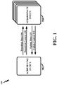
- FIG. 1 illustrates a diagram 100 showing an example of various communications between a scheduling entity 102 and one or more subordinate entities 104 according to aspects of the present disclosure.
- the scheduling entity 102 is a node or device responsible for scheduling traffic in a wireless communication network, including various downlink (DL) and uplink (UL) transmissions.
- the scheduling entity 102 may sometimes be referred to as a scheduler, and/or any other suitable term without deviating from the scope of the present disclosure.
- the scheduling entity 102 may be, or may reside within, a base station, a base transceiver station, a radio base station, a radio transceiver, a transceiver function, a basic service set, an extended service set, an access point, a Node B, a user equipment (UE), a mesh node, a relay, a peer, and/or any other suitable device.
- a base station a base transceiver station
- a radio base station a radio transceiver
- a transceiver function a basic service set, an extended service set, an access point, a Node B, a user equipment (UE), a mesh node, a relay, a peer, and/or any other suitable device.
- the subordinate entity 104 is a node or device that receives scheduling and/or control information, including but not limited to scheduling grants, synchronization or timing information, or other control information from another entity in the wireless communication network, such as the scheduling entity 102.
- the subordinate entity 104 may be a referred to as a schedulee, and/or any other suitable term without deviating from the scope of the present disclosure.
- the subordinate entity 104 may be, or may reside within, a UE, a cellular phone, a smart phone, a mobile station, a subscriber station, a mobile unit, a subscriber unit, a wireless unit, a remote unit, a mobile device, a wireless device, a wireless communications device, a remote device, a mobile subscriber station, an access terminal, a mobile terminal, a wireless terminal, a remote terminal, a handset, a terminal, a user agent, a mobile client, a client, a mesh node, a peer, a session initiation protocol phone, a laptop, a notebook, a netbook, a smartbook, a personal digital assistant, a satellite radio, a global positioning system device, a multimedia device, a video device, a digital audio player, a camera, a game console, an entertainment device, a vehicle component, a wearable computing device (e.g., a smart watch, glasses, a health or fitness tracker, etc.), an appliance, a
- 'control channel(s)' may sometimes be used to communicate grant information.
- the scheduling entity 102 may transmit DL data channel(s) 106 and DL control channel(s) 108.
- the subordinate entity 104 may transmit UL data channel(s) 110 and UL control channel(s) 112.
- the channels illustrated in FIG. 1 are not necessarily all of the channels that may be utilized by the scheduling entity 102 and/or the subordinate entity 104. Those of ordinary skill in the art will recognize that other channels may be utilized in addition to those illustrated, such as other data, control, and feedback channels.
- the term 'downlink' or 'DL' may refer to a point-to-multipoint transmission originating at the scheduling entity 102
- the term 'uplink' or 'UL' may refer to a point-to-point transmission originating at the subordinate entity 104.
- the term(s) 'communicate' and/or 'communicating' refer to transmission and/or reception.
- One of ordinary skill in the art will understand that many types of technologies may perform such communication without deviating from the scope of the present disclosure.
- the term 'DL-centric time-division duplex (TDD) subframe' refers to a TDD subframe in which a substantial proportion (e.g., majority) of the information is communicated in the DL direction, even though some of the information may be communicated in the UL direction.
- TDD time-division duplex
- the term 'UL-centric TDD subframe' refers to a TDD subframe in which a substantial proportion (e.g., majority) of the information is communicated in the UL direction, even though some information may be communicated in the DL direction.
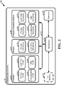
- FIG. 2 is a diagram 200 illustrating an example of a hardware implementation of the scheduling entity 102 according to various aspects of the present disclosure.
- the scheduling entity 102 may include a user interface 212.
- the user interface 212 may be configured to receive one or more inputs from a user of the scheduling entity 102.
- the user interface 212 may be a keypad, a display, a speaker, a microphone, a joystick, and/or any other suitable component of the scheduling entity 102.
- the user interface 212 may exchange data via the bus interface 208.
- the scheduling entity 102 may also include a transceiver 210.
- the transceiver 210 may be configured to receive data and/or transmit data in communication with another apparatus.
- the transceiver 210 provides a means for communicating with another apparatus via a wired or wireless transmission medium.
- the transceiver 210 may be configured to perform such communications using various types of technologies without deviating from the scope of the present disclosure.
- the scheduling entity 102 may also include a memory 214, one or more processors 204, a computer-readable medium 206, and a bus interface 208.
- the bus interface 208 may provide an interface between a bus 216 and the transceiver 210.
- the memory 214, the one or more processors 204, the computer-readable medium 206, and the bus interface 208 may be connected together via the bus 216.
- the processor 204 may be communicatively coupled to the transceiver 210 and/or the memory 214.
- the processor 204 may include a precoder circuit 220.
- the precoder circuit 220 may include hardware components and/or may perform various algorithms that provide the means for selecting a precoder mode for a transmission.
- the processor 204 may also include a cyclic prefix (CP) circuit 221.
- the CP circuit 221 may include hardware components and/or may perform various algorithms that provide the means for changing a CP length based on the selected precoder mode.
- the processor 204 may also include a communication circuit 222.
- the communication circuit 222 may include hardware components and/or may perform various algorithms that provide the means for transmitting a signal that includes the changed CP length.
- the CP circuit 221 may also include hardware components and/or may perform various algorithms that provide the means for using the selected precoder mode to lookup a value by which to change a nominal CP length.
- the communication circuit 222 may also include hardware components and/or may perform various algorithms that provide the means for transmitting information indicating the changed CP length to a receiver of the signal after changing the CP length.
- the communication circuit 222 may also include hardware components and/or may perform various algorithms that provide the means for transmitting information indicating the selected precoder mode to a receiver of the signal after selecting the precoder mode.
- the means for selecting the precoder mode may be configured according to any one or more of various aspects described in greater detail herein.
- the means for selecting the precoder mode may be configured for receiving feedback information from a receiver of the signal, wherein the feedback information indicates whether the receiver requests a change to the CP length, and selecting the precoder mode based on the feedback information.
- the means for selecting the precoder mode may be configured for receiving a reference signal indicating a condition of a communication channel, and selecting a precoder mode that results in a smallest relative delay spread based on the received reference signal.
- the means for selecting the precoder mode may be configured for receiving a reference signal indicating a condition of a communication channel, and selecting a precoder mode that results in a largest relative delay spread compression based on the received reference signal. In some configurations, the means for selecting the precoder mode may be configured for receiving a reference signal indicating a condition of a communication channel, and selecting a precoder mode that results in a largest relative beamforming gain based on the received reference signal. In some configurations, the means for selecting the precoder mode may be configured for receiving a reference signal indicating a condition of a communication channel, and selecting a precoder mode that results in a largest relative throughout based on the received reference signal.
- processor 204 of the scheduling entity 102.
- various circuits 220, 221, 222 are described above, one of ordinary skill in the art will understand that the processor 204 may also include various other circuits 223 that are in addition and/or alternative(s) to the aforementioned circuits 220, 221, 222.
- Such other circuits 223 may provide the means for performing any one or more of the functions, methods, processes, features and/or aspects described herein.
- the computer-readable medium 206 may include various computer-executable instructions.
- the computer-executable instructions may include computer-executable code configured to perform various functions and/or enable various aspects described herein.
- the computer-executable instructions may be executed by various hardware components (e.g., the processor 204 and/or any of its circuits 220, 221, 222, 223) of the scheduling entity 102.
- the computer-executable instructions may be a part of various software programs and/or software modules.
- the computer-readable medium 206 may include precoder instructions 240.
- the precoder instructions 240 may include computer-executable instructions configured for selecting a precoder mode for a transmission.
- the computer-readable medium 206 may also include CP instructions 241.
- the CP instructions 240 may include computer-executable instructions configured for changing a CP length based on the selected precoder mode.
- the computer-readable medium 206 may also include communication instructions 242.
- the communication instructions 242 may include computer-executable instructions configured for transmitting a signal that includes the changed CP length.
- the CP instructions 241 may also include computer-executable instructions configured for using the selected precoder mode to lookup a value by which to change a nominal CP length.
- the communication instructions 242 may also include computer-executable instructions configured for transmitting information indicating the changed CP length to a receiver of the signal after changing the CP length.
- the communication instructions 242 may also include computer-executable instructions configured for transmitting information indicating the selected precoder mode to a receiver of the signal after selecting the precoder mode.
- the precoder instructions 240 may include computer-executable instructions configured according to any one or more of various aspects described in greater detail herein.
- the precoder instructions 240 may be configured for selecting the precoder mode may be configured for receiving feedback information from a receiver of the signal, wherein the feedback information indicates whether the receiver requests a change to the CP length, and selecting the precoder mode based on the feedback information.
- the precoder instructions 240 may be configured for receiving a reference signal indicating a condition of a communication channel, and selecting a precoder mode that results in a smallest relative delay spread based on the received reference signal.
- the precoder instructions 240 may be configured for receiving a reference signal indicating a condition of a communication channel, and selecting a precoder mode that results in a largest relative delay spread compression based on the received reference signal. In some configurations, the precoder instructions 240 may be configured for receiving a reference signal indicating a condition of a communication channel, and selecting a precoder mode that results in a largest relative beamforming gain based on the received reference signal. In some configurations, the precoder instructions 240 may be configured for receiving a reference signal indicating a condition of a communication channel, and selecting a precoder mode that results in a largest relative throughout based on the received reference signal.
- the foregoing description provides a non-limiting example of the computer-readable medium 206 of the scheduling entity 102.
- various computer-executable instructions 240, 241, 242 are described above, one of ordinary skill in the art will understand that the computer-readable medium 206 may also include various other computer-executable instructions 243 that are in addition and/or alternative(s) to the aforementioned computer-executable instructions 240, 241, 242.
- Such other computer-executable instructions 243 may be configured for any one or more of the functions, methods, processes, features and/or aspects described herein.
- the memory 214 may include various memory modules.
- the memory modules may be configured to store, and have read therefrom, various values and/or information by the processor 204, or any of its circuits 220, 221, 222, 223.
- the memory modules may also be configured to store, and have read therefrom, various values and/or information upon execution of the computer-executable code included in the computer-readable medium 206, or any of its instructions 240, 241, 242, 243.
- the memory 214 may include precoder information 230.
- the precoder information 230 may include various types, quantities, configurations, arrangements, and/or forms of information related to a precoder or precoder mode according to one or more of the various aspects described in greater detail herein.
- the memory 214 may also include CP information 231.
- the CP information 231 may include various types, quantities, configurations, arrangements, and/or forms of information related to a CP as described in greater detail herein. Although various types of data of the memory 214 are described above, one of ordinary skill in the art will understand that the memory 214 may also include various other data that are in addition and/or alternative(s) to the aforementioned information 230, 231. Such other data may be associated with any one or more of the functions, methods, processes, features and/or aspects described herein.
- an element, or any portion of an element, or any combination of elements may be implemented with a processing system that includes one or more processors 204.
- the one or more processors 204 include microprocessors, microcontrollers, digital signal processors (DSPs), field programmable gate arrays (FPGAs), programmable logic devices (PLDs), state machines, gated logic, discrete hardware circuits, and other suitable hardware configured to perform the various functionality described throughout this disclosure.
- the processing system may be implemented with a bus architecture, represented generally by the bus 216 and bus interface 208.
- the bus 216 may include any number of interconnecting buses and bridges depending on the specific application of the processing system and the overall design constraints.
- the bus 216 may link together various circuits including the one or more processors 204, the memory 214, and the computer-readable medium 206.
- the bus 216 may also link various other circuits such as timing sources, peripherals, voltage regulators, and power management circuits.
- the one or more processors 204 may be responsible for managing the bus 216 and general processing, including the execution of software stored on the computer-readable medium 206.
- the software when executed by the one or more processors 204, causes the processing system to perform the various functions described below for any one or more apparatuses.
- the computer-readable medium 206 may also be used for storing data that is manipulated by the one or more processors 204 when executing software.
- Software shall be construed broadly to mean instructions, instruction sets, code, code segments, program code, programs, subprograms, software modules, applications, software applications, software packages, routines, subroutines, objects, executables, threads of execution, procedures, functions, etc., whether referred to as software, firmware, middleware, microcode, hardware description language, or otherwise.
- the software may reside on the computer-readable medium 206.
- the computer-readable medium 206 may be a non-transitory computer-readable medium.
- a non-transitory computer-readable medium includes, by way of example, a magnetic storage device (e.g., hard disk, floppy disk, magnetic strip), an optical disk (e.g., a compact disc (CD) or a digital versatile disc (DVD)), a smart card, a flash memory device (e.g., a card, a stick, or a key drive), a random access memory (RAM), a read only memory (ROM), a programmable ROM (PROM), an erasable PROM (EPROM), an electrically erasable PROM (EEPROM), a register, a removable disk, and any other suitable medium for storing software and/or instructions that may be accessed and read by a computer.
- a magnetic storage device e.g., hard disk, floppy disk, magnetic strip
- an optical disk e.g., a compact disc (CD) or a digital versatile disc (DVD
- the computer-readable medium 206 may also include, by way of example, a carrier wave, a transmission line, and any other suitable medium for transmitting software and/or instructions that may be accessed and read by a computer.
- the computer-readable medium 206 may reside in the processing system, external to the processing system, or distributed across multiple entities including the processing system.
- the computer-readable medium 206 may be embodied in a computer program product.
- a computer program product may include a computer-readable medium in packaging materials.
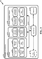
- FIG. 3 is a diagram 300 illustrating an example of a hardware implementation of the subordinate entity 104 according to various aspects of the present disclosure.
- the subordinate entity 104 may include a user interface 312.
- the user interface 312 may be configured to receive one or more inputs from a user of the subordinate entity 104.
- the user interface 312 may be a keypad, a display, a speaker, a microphone, a joystick, and/or any other suitable component of the subordinate entity 104.
- the user interface 312 may exchange data via the bus interface 308.
- the subordinate entity 104 may also include a transceiver 310.
- the transceiver 310 may be configured to receive data and/or transmit data in communication with another apparatus.
- the transceiver 310 provides a means for communicating with another apparatus via a wired or wireless transmission medium.
- the transceiver 310 may be configured to perform such communications using various types of technologies without deviating from the scope of the present disclosure.
- the subordinate entity 104 may also include a memory 314, one or more processors 304, a computer-readable medium 306, and a bus interface 308.
- the bus interface 308 may provide an interface between a bus 316 and the transceiver 310.
- the memory 314, the one or more processors 304, the computer-readable medium 306, and the bus interface 308 may be connected together via the bus 316.
- the processor 304 may be communicatively coupled to the transceiver 310 and/or the memory 314.
- the processor 304 may include a precoder circuit 320.
- the precoder circuit 320 may include hardware components and/or may perform various algorithms that provide the means for selecting a precoder mode for a transmission.
- the processor 304 may also include a CP circuit 321.
- the CP circuit 321 may include hardware components and/or may perform various algorithms that provide the means for changing a CP length based on the selected precoder mode.
- the processor 304 may also include a communication circuit 322.
- the communication circuit 322 may include hardware components and/or may perform various algorithms that provide the means for transmitting a signal that includes the changed CP length.
- the CP circuit 321 may also include hardware components and/or may perform various algorithms that provide the means for using the selected precoder mode to lookup a value by which to change a nominal CP length.
- the communication circuit 322 may also include hardware components and/or may perform various algorithms that provide the means for transmitting information indicating the changed CP length to a receiver of the signal after changing the CP length.
- the communication circuit 322 may also include hardware components and/or may perform various algorithms that provide the means for transmitting information indicating the selected precoder mode to a receiver of the signal after selecting the precoder mode.
- the means for selecting the precoder mode may be configured according to any one or more of various aspects described in greater detail herein.
- the means for selecting the precoder mode may be configured for receiving feedback information from a receiver of the signal, wherein the feedback information indicates whether the receiver requests a change to the CP length, and selecting the precoder mode based on the feedback information.
- the means for selecting the precoder mode may be configured for receiving a reference signal indicating a condition of a communication channel, and selecting a precoder mode that results in a smallest relative delay spread based on the received reference signal.
- the means for selecting the precoder mode may be configured for receiving a reference signal indicating a condition of a communication channel, and selecting a precoder mode that results in a largest relative delay spread compression based on the received reference signal. In some configurations, the means for selecting the precoder mode may be configured for receiving a reference signal indicating a condition of a communication channel, and selecting a precoder mode that results in a largest relative beamforming gain based on the received reference signal. In some configurations, the means for selecting the precoder mode may be configured for receiving a reference signal indicating a condition of a communication channel, and selecting a precoder mode that results in a largest relative throughout based on the received reference signal.
- processor 304 of the subordinate entity 104.
- various circuits 320, 321, 322 are described above, one of ordinary skill in the art will understand that the processor 304 may also include various other circuits 323 that are in addition and/or alternative(s) to the aforementioned circuits 320, 321, 322.
- Such other circuits 323 may provide the means for performing any one or more of the functions, methods, processes, features and/or aspects described herein.
- the computer-readable medium 306 may include precoder instructions 340.
- the precoder instructions 340 may include computer-executable instructions configured for selecting a precoder mode for a transmission.
- the computer-readable medium 306 may also include CP instructions 341.
- the CP instructions 340 may include computer-executable instructions configured for changing a CP length based on the selected precoder mode.
- the computer-readable medium 306 may also include communication instructions 342.
- the communication instructions 342 may include computer-executable instructions configured for transmitting a signal that includes the changed CP length.
- the CP instructions 341 may also include computer-executable instructions configured for using the selected precoder mode to lookup a value by which to change a nominal CP length.
- the communication instructions 342 may also include computer-executable instructions configured for transmitting information indicating the changed CP length to a receiver of the signal after changing the CP length.
- the communication instructions 342 may also include computer-executable instructions configured for transmitting information indicating the selected precoder mode to a receiver of the signal after selecting the precoder mode.
- the precoder instructions 340 may include computer-executable instructions configured according to any one or more of various aspects described in greater detail herein.
- the precoder instructions 340 may be configured for selecting the precoder mode may be configured for receiving feedback information from a receiver of the signal, wherein the feedback information indicates whether the receiver requests a change to the CP length, and selecting the precoder mode based on the feedback information.
- the precoder instructions 340 may be configured for receiving a reference signal indicating a condition of a communication channel, and selecting a precoder mode that results in a smallest relative delay spread based on the received reference signal.
- the precoder instructions 340 may be configured for receiving a reference signal indicating a condition of a communication channel, and selecting a precoder mode that results in a largest relative delay spread compression based on the received reference signal. In some configurations, the precoder instructions 340 may be configured for receiving a reference signal indicating a condition of a communication channel, and selecting a precoder mode that results in a largest relative beamforming gain based on the received reference signal. In some configurations, the precoder instructions 340 may be configured for receiving a reference signal indicating a condition of a communication channel, and selecting a precoder mode that results in a largest relative throughout based on the received reference signal.
- the computer-readable medium 306 may also include various other computer-executable instructions 343 that are in addition and/or alternative(s) to the aforementioned computer-executable instructions 340, 341, 342.
- Such other computer-executable instructions 343 may be configured for any one or more of the functions, methods, processes, features and/or aspects described herein.
- the memory 314 may include various memory modules.
- the memory modules may be configured to store, and have read therefrom, various values and/or information by the processor 304, or any of its circuits 320, 321, 322, 323.
- the memory modules may also be configured to store, and have read therefrom, various values and/or information upon execution of the computer-executable code included in the computer-readable medium 306, or any of its instructions 340, 341, 342, 343.
- the memory 314 may include precoder information 330.
- the precoder information 330 may include various types, quantities, configurations, arrangements, and/or forms of information related to a precoder or precoder mode according to one or more of the various aspects described in greater detail herein.
- the memory 314 may also include CP information 331.
- the CP information 331 may include various types, quantities, configurations, arrangements, and/or forms of information related to a CP as described in greater detail herein. Although various types of data of the memory 314 are described above, one of ordinary skill in the art will understand that the memory 314 may also include various other data that are in addition and/or alternative(s) to the aforementioned information 330, 331. Such other data may be associated with any one or more of the functions, methods, processes, features and/or aspects described herein.
- an element, or any portion of an element, or any combination of elements may be implemented with a processing system that includes one or more processors 304.
- the one or more processors 304 include microprocessors, microcontrollers, DSPs, FPGAs, PLDs, state machines, gated logic, discrete hardware circuits, and other suitable hardware configured to perform the various functionality described throughout this disclosure.
- the processing system may be implemented with a bus architecture, represented generally by the bus 316 and bus interface 308.
- the bus 316 may include any number of interconnecting buses and bridges depending on the specific application of the processing system and the overall design constraints.
- the bus 316 may link together various circuits including the one or more processors 304, the memory 314, and the computer-readable medium 306.
- the bus 316 may also link various other circuits such as timing sources, peripherals, voltage regulators, and power management circuits.
- the one or more processors 304 may be responsible for managing the bus 316 and general processing, including the execution of software stored on the computer-readable medium 306.
- the software when executed by the one or more processors 304, causes the processing system to perform the various functions described below for any one or more apparatuses.
- the computer-readable medium 306 may also be used for storing data that is manipulated by the one or more processors 304 when executing software.
- Software shall be construed broadly to mean instructions, instruction sets, code, code segments, program code, programs, subprograms, software modules, applications, software applications, software packages, routines, subroutines, objects, executables, threads of execution, procedures, functions, etc., whether referred to as software, firmware, middleware, microcode, hardware description language, or otherwise.
- the software may reside on the computer-readable medium 306.
- the computer-readable medium 306 may be a non-transitory computer-readable medium.
- a non-transitory computer-readable medium includes, by way of example, a magnetic storage device (e.g., hard disk, floppy disk, magnetic strip), an optical disk (e.g., a CD or a DVD), a smart card, a flash memory device (e.g., a card, a stick, or a key drive), a RAM, a ROM, a PROM, an EPROM, an EEPROM, a register, a removable disk, and any other suitable medium for storing software and/or instructions that may be accessed and read by a computer.
- a magnetic storage device e.g., hard disk, floppy disk, magnetic strip
- an optical disk e.g., a CD or a DVD
- a smart card e.g., a flash memory device (e.g., a card, a stick, or a key drive)
- a RAM random access memory
- the computer-readable medium 306 may also include, by way of example, a carrier wave, a transmission line, and any other suitable medium for transmitting software and/or instructions that may be accessed and read by a computer.
- the computer-readable medium 306 may reside in the processing system, external to the processing system, or distributed across multiple entities including the processing system.
- the computer-readable medium 306 may be embodied in a computer program product.
- a computer program product may include a computer-readable medium in packaging materials.
- FIG. 4 illustrates a diagram 400 showing the scheduling entity 102 in communication with the subordinate entity 104 in an access network according to aspects of the present disclosure.
- upper layer packets from the core network are provided to a controller/processor 475.
- the controller/processor 475 implements the functionality of the L2 layer.
- the controller/processor 475 provides header compression, ciphering, packet segmentation and reordering, multiplexing between logical and transport channels, and radio resource allocations to the subordinate entity 104 based on various priority metrics.
- the controller/processor 475 is also responsible for HARQ operations, retransmission of lost packets, and signaling to the subordinate entity 104.
- the transmit (TX) processor 416 implements various signal processing functions for the L1 layer (i.e., physical layer).
- the signal processing functions include coding and interleaving to facilitate forward error correction (FEC) at the subordinate entity 104 and mapping to signal constellations based on various modulation schemes (e.g., binary phase-shift keying (BPSK), quadrature phase-shift keying (QPSK), M-phase-shift keying (M-PSK), M-quadrature amplitude modulation (M-QAM)).
- FEC forward error correction
- BPSK binary phase-shift keying
- QPSK quadrature phase-shift keying
- M-PSK M-phase-shift keying
- M-QAM M-quadrature amplitude modulation
- Each stream is then mapped to an OFDM subcarrier, multiplexed with a reference signal (e.g., pilot) in the time and/or frequency domain, and then combined together using an Inverse Fast Fourier Transform (IFFT) to produce a physical channel carrying a time domain OFDM symbol stream.
- the OFDM stream is spatially precoded to produce multiple spatial streams.
- Channel estimates from a channel estimator 474 may be used to determine the coding and modulation scheme, as well as for spatial processing.
- the channel estimate may be derived from a reference signal and/or channel condition feedback transmitted by the subordinate entity 104.
- Each spatial stream may then be provided to a different antenna 420 via a separate transmitter 418TX.
- Each transmitter 418TX may modulate an RF carrier with a respective spatial stream for transmission.
- Each receiver 418RX may be configured to receive wireless signals of various types, schemes, configurations, and/or modulations.
- the RX processor 470 may be configured to receive, decode, demodulate, and/or otherwise process any UL signal that is received by the receiver 418RX.
- the UL signal is adapted for orthogonal frequency-division multiple access (OFDMA), which is a multi-user version of the modulation scheme referred to as orthogonal frequency-division multiplexing (OFDM).
- OFDM orthogonal frequency-division multiplexing
- the UL signal is adapted for single-carrier frequency-division multiple access (SC-FDMA). Such signals may even co-exist in some examples.
- the RX processor 470 and the receiver 418RX may perform UL communication using waveforms that may co-exist in OFDMA and SC-FDMA.
- each receiver 454RX receives a signal through its respective antenna 452.
- Each receiver 454RX recovers information modulated onto an RF carrier and provides the information to the receive (RX) processor 456.
- the RX processor 456 implements various signal processing functions of the L1 layer.
- the RX processor 456 may perform spatial processing on the information to recover any spatial streams destined for the subordinate entity 104. If multiple spatial streams are destined for the subordinate entity 104, they may be combined by the RX processor 456 into a single OFDM symbol stream.
- the RX processor 456 then converts the OFDM symbol stream from the time-domain to the frequency domain using a Fast Fourier Transform (FFT).
- FFT Fast Fourier Transform
- the frequency domain signal comprises a separate OFDM symbol stream for each subcarrier of the OFDM signal.
- the symbols on each subcarrier, and the reference signal, are recovered and demodulated by determining the most likely signal constellation points transmitted by the scheduling entity 102. These soft decisions may be based on channel estimates computed by the channel estimator 458.
- the soft decisions are then decoded and deinterleaved to recover the data and control signals that were originally transmitted by the scheduling entity 102 on the physical channel.
- the data and control signals are then provided to the controller/processor 459.
- the controller/processor 459 implements the L2 layer.
- the controller/processor can be associated with a memory 460 that stores program codes and data.
- the memory 460 may be referred to as a computer-readable medium.
- the controller/processor 459 provides demultiplexing between transport and logical channels, packet reassembly, deciphering, header decompression, control signal processing to recover upper layer packets from the core network.
- the upper layer packets are then provided to a data sink 462, which represents all the protocol layers above the L2 layer.
- Various control signals may also be provided to the data sink 462 for L3 processing.
- the controller/processor 459 is also responsible for error detection using an acknowledgement (ACK) and/or negative acknowledgement (NACK) protocol to support HARQ operations.
- ACK acknowledgement
- NACK negative acknowledgement
- a data source 467 is used to provide upper layer packets to the controller/processor 459.
- the data source 467 represents all protocol layers above the L2 layer.
- the controller/processor 459 implements the L2 layer for the user plane and the control plane by providing header compression, ciphering, packet segmentation and reordering, and multiplexing between logical and transport channels based on radio resource allocations by the scheduling entity 102.
- the controller/processor 459 is also responsible for HARQ operations, retransmission of lost packets, and signaling to the scheduling entity 102.
- Channel estimates derived by a channel estimator 458 from a reference signal or feedback transmitted by the scheduling entity 102 may be used by the TX processor 468 to select the appropriate coding and modulation schemes, and to facilitate spatial processing.
- the spatial streams generated by the TX processor 468 may be provided to different antenna 452 via separate transmitters 454TX. Each transmitter 454TX may modulate an RF carrier with a respective spatial stream for transmission.
- Each transmitter 454TX may be configured to transmit wireless signals of various types, schemes, configurations, and/or modulations.
- the TX processor 468 may be configured to generate, encode, modulate, and/or otherwise produce any UL signal that is transmitted by the transmitter 454TX.
- the UL signal is adapted for OFDMA.
- the UL signal is adapted for SC-FDMA. Such signals may even co-exist in some examples.
- the TX processor 468 and the transmitter 454TX may perform UL communication using waveforms that co-exist in OFDMA and SC-FDMA.
- the UL transmission is processed at the scheduling entity 102 in a manner similar to that described in connection with the receiver function at the subordinate entity 104.
- Each receiver 418RX receives a signal through its respective antenna 420.
- Each receiver 418RX recovers information modulated onto an RF carrier and provides the information to a RX processor 470.
- the RX processor 470 may implement the L1 layer.
- the controller/processor 475 implements the L2 layer.
- the controller/processor 475 can be associated with a memory 476 that stores program codes and data.
- the memory 476 may be referred to as a computer-readable medium.
- the control/processor 475 provides demultiplexing between transport and logical channels, packet reassembly, deciphering, header decompression, control signal processing to recover upper layer packets from the subordinate entity 104.
- Upper layer packets from the controller/processor 475 may be provided to the core network.
- the controller/processor 475 is also responsible for error detection using an ACK and/or NACK protocol to support HARQ operations.
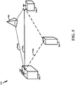
- FIG. 5 illustrates a diagram 500 showing an example of multipath communication according to aspects of the present disclosure.
- This example illustrates how a signal may take multiple paths as it propagates from the scheduling entity 102 to the subordinate entity 104.
- Path A represents a direct path from the scheduling entity 102 to the subordinate entity 104.
- the transmitted signal may also travel from the scheduling entity 102 to the subordinate entity 104 via indirect paths. Some paths may reflect off of various obstacles 502, 504 before reaching the subordinate entity 104.
- Path B represents a path in which the signal reflects off of an obstacle 502 that redirects the signal to the subordinate entity 104.
- Path C represents a path in which the signal reflects off of another obstacle 504 that redirects the signal to the subordinate entity 104.
- Path C is longer than Path B . Accordingly, the signal propagating in Path B will arrive at the subordinate entity 104 prior to the signal propagating in Path C . The signal propagating in Path A will arrive prior to both signals propagating in Path B and Path C .
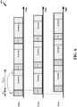
- FIG. 6 illustrates a diagram 600 showing an example of timelines corresponding to the multipath communication according to aspects of the present disclosure.
- FIG. 6 illustrates that the signal propagating in Path A arrives earlier in time relative to the signal propagating in Path B .
- FIG. 6 also illustrates that the signal propagating in Path B arrives earlier in time relative to the signal propagating in Path C .
- the signals illustrated in FIG. 6 show that each symbol may have a CP.
- a CP refers to a repeated portion of the symbol that precedes that symbol.
- a symbol is preceded by a CP, and that CP repeats a portion (e.g., an end portion) of that symbol.
- CP 1 repeats the end portion of Symbol 1 .
- the CP is discarded by the receiver (e.g., subordinate entity 104); however, the CP has various purposes.
- One of many purposes of the CP is to function as a guard interval for mitigating inter-symbol interference.
- CP 2 may mitigate interference between Symbol 1 and Symbol.
- the CP may have various lengths without deviating from the scope of the present disclosure.
- the CP length may utilize 5%-10% of the resources of the physical channel.
- any reference herein to 'length' may also refer to related concepts such as duration, time, period, bits, and other suitable concepts without deviating from the scope of the present disclosure.
- any reference herein to 'CP length' may also refer to CP overhead, CP duration, CP time, CP period, CP bits, and other suitable CP-related aspects without deviating from the scope of the present disclosure.
- the appropriate length for the CP also increases.
- One reason for this general relationship is that more time is needed for the energy from echoes (e.g., signals propagating in Path B and Path C ) of a particular symbol (e.g., Symbol 1 ) to dissipate prior to receiving another symbol (e.g., Symbol). Otherwise, the echoes from a preceding symbol (e.g., Symbol 1 ) may interfere with a current symbol (e.g., Symbol). Accordingly, in some circumstances, a relatively longer CP length may be appropriate as the number of paths increases.
- a CP length that is needlessly too long may adversely affect system performance (e.g., reduced throughput).
- the CP is typically discarded at the receiver (e.g., subordinate entity 104).
- the CP utilizes communication resources that may otherwise be utilized to carry information that will not be discarded at the receiver (e.g., subordinate entity 104).
- the appropriate length for the CP may differ under varying circumstances.
- FIG. 7 illustrates diagrams 700, 750 showing examples of times at which signals arrive at the subordinate entity 104.
- a first diagram 700 illustrates an example of times at which signals from Path A , Path B , and Path C arrive at the subordinate entity 104 when the scheduling entity 102 does not implement enhanced precoding for the transmission.
- precoding may be utilized by multi-antenna devices for wireless communication. Precoding may involve multiple data streams being emitted from transmit antennas with independent and appropriate weights such that the link throughout is maximized at the receiver (e.g., subordinate entity 104). Put in another way, precoding exploits transmit diversity by weighing information streams, sometimes using information or knowledge about the wireless communication channel. Precoding may support beamforming. Generally, beamforming refers to a spatial filtering technique used for directional signal transmission.
- the transmitter may apply various weights to various antennas of the transmitter (e.g., scheduling entity 102) to minimize multipath, thereby minimizing the duration of time over which echoes are detected at the receiver (e.g., subordinate entity 104), which may consequently reduce the CP length appropriate for that transmission.
- enhanced precoding techniques may provide substantial reductions in multipath and, consequently, minimize the CP length needed for particular transmissions.
- precoding and/or beamforming may be applied on a per-tone basis.
- per-tone beamforming/precoding may even further compress the delay spread (e.g., in massive multiple-input multiple output (MIMO) communication systems).
- MIMO massive multiple-input multiple output
- the second diagram 750 illustrates an example of times at which signals arrive at the subordinate entity 104 when enhanced precoding techniques are utilized by the scheduling entity 102.
- a comparison of the two diagrams 700, 750 reveals that enhanced precoding techniques may reduce the amount of time over which signal echoes are received at the subordinate entity 104. For example, instead of arriving near times T 2 and T 3 , the signals in Path B and Path C arrive near time T 1 when enhanced precoding techniques are utilized by the scheduling entity 102.
- the precoding applied to the transmit signal results in a collapse of many of the multipath echoes into essentially a single energy peak.
- FIG. 8 illustrates diagrams 800, 850 showing additional examples of times at which signals arrive at the subordinate entity 104.
- a first diagram 800 illustrates an example of times at which signals arrive at the subordinate entity 104 when enhanced precoding techniques are not utilized by the scheduling entity 102.
- the second diagram 850 illustrates an example of times at which signals arrive at the subordinate entity 104 when enhanced precoding techniques are utilized by the scheduling entity 102.
- a comparison of the two diagrams 800, 850 reveals that enhanced precoding techniques may reduce the duration of time over which signal echoes are received at the subordinate entity 104.
- the diagrams 800, 850 may sometimes be referred to as power delay profiles (PDPs), each of which may include a plot of the power of the channel impulse response.
- a channel e.g., a wideband channel
- 'taps' or 'chips For example, in the first figure 800 of FIG. 8 , nine (9) multipath components (e.g., taps or chips) are illustrated, each having a different amplitude.
- These multipath components may correspond to different paths that the signal traveled or propagated from N T transmit antenna(s) (e.g., at the scheduling entity 102) to N R receive antenna(s) (e.g., at the subordinate entity 104).
- H K represents a vector with N T complex numbers that correspond to the channel estimate of the k th subcarrier for each transmit-receive (TX-RX) antenna pair.
- a subset of £ may be referred to as C . That is, C may refer to a subset of indices of multipath components of interest.
- the selection of C may affect the precoder design. For instance, C may be selected such that one or more performance metrics are optimized or maximized.
- performance metrics such as relative delay spread, relative delay spread compression, relative beamforming gain, relative throughput, and many others.
- G k may represent the effective channel that the receiver (e.g., subordinate entity 104) may observe after the transmitter (e.g., scheduling entity 102) has applied the precoder at each subcarrier.
- DFT discrete Fourier transform
- the PDP after applying such a precoder may be defined by
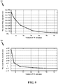
- FIG. 9 illustrates diagrams 900, 950 showing examples of maximum delay spread for various signals transmitted by the scheduling entity 102.
- 'delay spread' is a measure related to the multipath of a communication channel.
- the delay spread may be interpreted as the difference between the arrival time of the earliest significant multipath signal (e.g., the signal propagating in Path A ) and the arrival time of the latest significant multipath signal (e.g., the signal propagating in Path C ).
- the delay spread may be used in the characterization of wireless communication channels.
- a reduction in delay spread may sometimes be referred to as 'delay spread compression' without deviating from the scope of the present disclosure.
- Such reductions of delay spread e.g., delay spread compression
- delay spread compression may be realized because the precoding applied to the transmit signal results in a collapse of many of the multipath echoes into essentially a single energy peak.
- 'maximum delay spread' refers to the duration of time or number of time samples needed for a received symbol's energy to fall a certain amount (e.g., 20 decibels (dB)) below the average power of the symbol.
- maximum delay spread may refer to a measure of how much time is needed for the power (after the end of the symbol) to be a certain amount (e.g., -20 dB) lower than the average energy of the symbol.
- a first diagram 900 illustrates an example of various maximum delay spreads when enhanced precoding techniques are not utilized by the scheduling entity 102.
- the second diagram 950 illustrates an example of various maximum delay spreads when enhanced precoding techniques are utilized by the scheduling entity 102.
- a comparison of the two diagrams 900, 950 reveals that enhanced precoding techniques may reduce maximum delay spreads. For example, n number of TX antennas may have a maximum delay spread of 10 x +500 nanoseconds (where x represents any positive value) when enhanced precoding techniques are not utilized by the scheduling entity 102, whereas n number of TX antennas may have a maximum delay spread of x +4 nanoseconds when enhanced precoding techniques are utilized by the scheduling entity 102.
- FIG. 10 illustrates diagrams 1000, 1050 showing aspects associated with varying the number of paths used in a precoder mode.
- the number of paths used in the precoder mode refers to the number of paths that the precoder mode takes into account when weighing the various signals transmitted by its antennas.
- a first diagram 1000 illustrates how the number of paths used in the precoder mode may affect the root-mean-square (RMS) delay spread.
- the RMS delay spread corresponds to the standard deviation of the delays of the signal echoes (e.g., reflections).
- the RMS delay spread may indicate the variability of the arrival times of the signal echoes (e.g., reflections).
- a receiver may align reception of its signal(s)/symbol(s) with the average delay spread of the multipath transmission. However, the receiver may also consider the variability (e.g., deviations) of the delay spreads. In other words, the same average delay spread may have different RMS delay spread values, depending on the delay variability of the signal echoes (e.g., reflections). Accordingly, in some circumstances, the RMS delay spread may be a factor used in CP length selection. For instance, the receiver may select a CP length that accommodates for a certain percentage or proportion of the delays in the signal echoes (e.g., reflections). In the first diagram 1000 illustrated in FIG. 10 , RMS delay spread is measured in units of nanoseconds.
- the first diagram 1000 illustrates that the RMS delay spread decreases as the number of paths used in the precoder mode increases. For example, when the number of paths used in the precoder mode increases from 1 p to 6 p (wherein p represents any positive integer), the RMS delay spread decreases from approximately a +360 to approximately a +40 (wherein a represents any positive value). However, in another part, the first diagram 1000 illustrates that the RMS delay spread may remain relatively constant or even increase as the number of paths used in the precoder mode increases. For example, when the number of paths used in the precoder mode increases from 6 p to 9 p , the RMS delay spread remains relatively constant (at approximately a +40) and thereafter increases (from approximately a +40 to approximately a +80).
- a second diagram 1050 illustrates how the number of paths used in the precoder mode may affect beamforming gain.
- beamforming gain is measured in units of decibels.
- beamforming gain refers to the energy gain or power gain achieved as a result of precoding the transmit signal prior to wireless transmission.
- this diagram 1050 illustrates that the main path energy increases substantially as the number of paths include in the precoder mode is increased.
- this diagram 1050 illustrates that the multipath energy remains relatively constant, even as the number of paths used in the precoder mode varies.
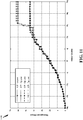
- FIG. 11 illustrates a diagram 1100 showing an example of a relationship between signal quality and throughput when a precoder mode that could lead to a significant delay spread reduction is used. This relationship is shown for various CP lengths for a channel that would typically need a CP length of 7 p in order to reach the peak throughput of the system. In this example, throughput is measured in megabits per second (Mbps), and CP length is measured in microseconds.
- the 'signal quality' shown in FIG. 11 and described herein may refer to a carrier to interference-plus-noise ratio (CINR), signal-to-noise ratio (SNR), and/or various other suitable measures of signal quality.
- CINR carrier to interference-plus-noise ratio
- SNR signal-to-noise ratio
- this diagram 1100 shows that a reduction in CP length may sometimes result in a reduction in throughput when the signal quality is relatively high.
- the signal quality is relatively high (e.g., 3 q through 5 q )
- a reduction in the CP length from 5 p to 2 p results in a substantial reduction in throughput (e.g., a reduction from 6 z to 4.5 z ), wherein p and z may each represent any positive value.
- this diagram 1000 shows that a reduction in CP length does not always result in a reduction in throughput, and, in some scenarios, results in an increase in the peak throughput. This may happen because a shorter CP length may still be enough to handle the compressed delay spread.
- a relatively higher peak throughput may be achieved, which may be because the CP length is relatively shorter, thereby enabling relatively more data information to be transmitted.
- the signal quality is relatively high (e.g., 3 q through 5 q )
- neither a reduction in the CP length from 2 p to p nor a reduction in the CP length from 7 p to 5 p results in a substantial reduction in throughput, which may be due to the compressed delay spread that results by using a specific precoder mode.
- FIG. 12 illustrates a diagram 1200 showing an example implementation according to aspects of the present disclosure.
- Block 1206 conceptually represents precoder mode selection.
- precoder mode selection refers to the selection of a precoder mode for various types of wireless communication.
- a 'precoder mode' may refer to and/or include a precoder type, a precoder configuration, a precoder scheme, a precoder setting, a precoder parameter, a precoder weight, and/or any other suitable aspect associated with a precoder mode without deviating from the scope of the present disclosure.
- the precoder mode may correspond to a particular transmission mode (TM).
- TM transmission mode
- an apparatus may infer the precoder mode based on the TM.
- Precoder mode selection may be based on many types of information without deviating from the scope of the present disclosure.
- a non-limiting example of such information is a received reference signal, which is represented by block 1202.
- a subordinate entity 104 may transmit a reference signal (e.g., a sounding signal) to the scheduling entity 102.
- the reference signal may include various types of information, such as a condition or a state of the wireless communication channel (e.g., without any precoding).
- the scheduling entity 102 may select an appropriate precoder mode.
- the particular precoder mode selected by the scheduling entity may differ in varying configurations. In some configurations, the scheduling entity 102 may select the precoder mode that results in a smallest relative delay spread.
- the scheduling entity 102 may select the precoder mode that results in a largest relative delay spread compression. Aspects pertaining to delay spread and delay spread compression are described in greater detail with reference to FIGS. 9 and 10 and therefore will not be repeated. In some configurations, the scheduling entity 102 may select the precoder mode that results in a largest relative beamforming gain. Aspects pertaining to beamforming gain are described in greater detail with reference to FIG. 10 and therefore will not be repeated. In some configurations, the scheduling entity 102 may select the precoder mode that results in a largest relative throughput. Aspects pertaining to throughput are described in greater detail with reference to FIG. 11 and therefore will not be repeated.
- the scheduling entity 102 may transmit a signal to the subordinate entity 104, and the subordinate entity 104 may report feedback information back to the scheduling entity 102.
- the feedback information may pertain to the CP length, the delay spread, the throughput, and/or various other suitable aspects without deviating from the scope of the present disclosure.
- the feedback information may indicate whether the subordinate entity 104 requests a change to the CP length.
- the feedback information may also be in various forms and/or configurations without deviating from the scope of the present disclosure.
- the feedback information may be in the form of a single bit (e.g., a happy bit), which may indicate whether the subordinate entity 104 requests a change to the CP length.
- the feedback information may also include an additional bit. In the event that the subordinate entity 104 does request a change to the CP length, this additional bit may indicate whether that change is an increase in the CP length or a decrease in the CP length. Based on such feedback information, the scheduling entity 102 may select a particular precoder mode.
- Block 1208 conceptually represents the selected precoder mode.
- Block 1210 conceptually represents CP length change.
- the change in CP length is based on the selected precoder mode.
- the CP length is not based on the selected precoder mode.
- the CP length may be fixed or predetermined.
- the CP length may sometimes vary based on information about the wireless communication channel, but not the selected precoder mode. In other words, existing systems may change the CP length in the same way even when the selected precoder mode varies.
- selecting a particular precoder mode does not necessarily affect how the CP length is changed.
- changing the CP length based on the precoder mode selection has many advantages over existing systems. For example, because the selected precoder mode may be able to estimate the delay spread (or delay spread compression) of the wireless transmission, the transmitter may be aware of the appropriate CP length for that particular wireless transmission.
- the appropriate CP length may long enough to minimize inter-symbol interference (as described in greater detail above, e.g., with reference to FIG. 6 ) but not so long that the CP length adversely impacts throughput (as described in greater detail above, e.g., with reference to FIGS. 6 and 11 ). Accordingly, enabling the scheduling entity 102 to change the CP length based on the precoder mode selection may increase efficiency of the wireless communication.
- the mechanism and/or technique by which the scheduling entity 102 implements the change of the CP length based on the selected precoder mode may vary based on specific design constraints of the specific wireless communication device, network, and/or technology. Although some examples of such mechanisms and/or techniques may be described herein, one of ordinary skill in the art will understand that various other alternatives are also within the scope of the present disclosure.
- the scheduling entity 102 may change the CP length by using the selected precoder mode to lookup a value by which to change a nominal CP length. For instance, a lookup table may store such a value.
- the value may be a fixed quantity (e.g., any real number), a multiplier (e.g., 2 x ), a fraction (e.g., 1 ⁇ 2), and/or any other suitable parameter by which a nominal (e.g., default, predetermined, preset, previous, etc.) CP length can be changed.
- a nominal e.g., default, predetermined, preset, previous, etc.
- CP length e.g., 1 ⁇ 2
- Such values may be updated from time to time based on various system parameters, network conditions, and other suitable triggers.
- Each of these values may be mapped to a particular precoder mode. Based on the selected precoder mode, the corresponding CP length may be retrieved and used to change the CP length.
- Block 1212 conceptually represents signal transmission.
- the transmitted signal may be precoded using the selected precoder mode, as described above with reference to blocks 1206, 1208.
- the transmitted signal may also include the changed CP length, as described above with reference to block 1210.
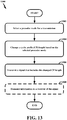
- FIG. 13 illustrates a diagram 1300 showing various methods and/or processes performed by the scheduling entity 102.
- the scheduling entity 102 may select a precoder mode for a transmission.
- the scheduling entity 102 may select the precoder mode based on feedback information received from the subordinate entity 104.
- the feedback information may indicate whether the subordinate entity 104 requests a change to the CP length.
- the scheduling entity 102 may select the precoder mode based on a reference signal received from the subordinate entity 104. Based on the reference signal, the scheduling entity 102 may select the precoder mode that results in the smallest relative delay spread, a largest relative delay spread compression, a largest beamforming gain, and/or a largest relative throughput.
- the scheduling entity 102 may change a CP length based on the selected precoder mode. In some examples, the scheduling entity 102 may change the CP length by using the selected precoder mode to lookup a value by which to change a nominal CP length. Various other techniques and/or mechanisms for changing the CP length based on the selected precoder mode are within the scope of the present disclosure.
- the scheduling entity 102 may transmit a signal that includes the changed CP length. In some examples, the signal may be precoded using the selected precoder mode. Additional description pertaining to precoding and CP length is provided herein, e.g., with reference to FIG. 6 , and therefore will not be repeated.
- the scheduling entity 102 may transmit certain information to a receiver (e.g., subordinate entity 104) of the signal.
- a receiver e.g., subordinate entity 104 of the signal.
- such information may indicate the changed CP length.
- such information may indicate the selected precoder mode.
- the receiver e.g., subordinate entity 104 may be prepared for receiving the precoded signal that includes the changed CP length. For example, the receiver will have information about the portion of the received signal that corresponds to the CP length.
- FIG. 13 The methods and/or processes described with reference to FIG. 13 are provided for illustrative purposes and are not intended to limit the scope of the present disclosure. The methods and/or processes described with reference to FIG. 13 may be performed in sequences different from those illustrated therein without deviating from the scope of the present disclosure. Additionally, some or all of the methods and/or processes described with reference to FIG. 13 may be performed individually and/or together without deviating from the scope of the present disclosure. It is to be understood that the specific order or hierarchy of steps in the methods disclosed is an illustration of exemplary processes. Based upon design preferences, it is understood that the specific order or hierarchy of steps in the methods may be rearranged. The accompanying method claims present elements of the various steps in a sample order, and are not meant to be limited to the specific order or hierarchy presented unless specifically recited therein.
Description
- Aspects of the present disclosure relate, generally, to wireless communication systems and, more particularly, to changing the cyclic prefix (CP) length based on precoder mode selection.
- Wireless communication networks are widely deployed to provide various communication services such as telephony, video, data, messaging, broadcasts, and so on. Such networks, which are usually multiple access networks, support communication for multiple users by sharing the available network resources. Within such wireless networks a variety of data services may be provided, including voice, video, and emails. The spectrum allocated to such wireless communication networks can include licensed spectrum and/or unlicensed spectrum. Licensed spectrum is generally restricted in its use for wireless communication except for licensed use as regulated by a governmental body or other authority within a given region. Unlicensed spectrum is generally free to use, within limits, without the purchase or use of such a license. As the demand for mobile broadband access continues to increase, research and development continue to advance wireless communication technologies to meet the growing demand for mobile broadband access and to enhance the overall user experience.
- Document Malkin et al.Transmitter Precoding for Insufficient-Cyclic-Prefix Distortion in Multicarrier Systems. In: VTC Spring 2008 - IEEE Vehicular Technology Conference, 11-14 May 2008, Singapore, Print ISBN: 978-1-4244-1644-8 proposes low-complexity insufficient-cyclic-prefix distortion reduction algorithms to maximize the data-rate.
- The invention is defined by the independent claims. The following presents a simplified summary of one or more aspects of the present disclosure, in order to provide a basic understanding of such aspects. This summary is not an extensive overview of all contemplated features of the disclosure, and is intended neither to identify key or critical elements of all aspects of the disclosure nor to delineate the scope of any or all aspects of the disclosure. Its sole purpose is to present some concepts of one or more aspects of the disclosure in a simplified form as a prelude to the more detailed description that is presented later.
- In one aspect, the present disclosure provides an apparatus for wireless communication. The apparatus includes a transceiver, a memory, and at least one processor communicatively coupled to the transceiver and the memory. The at least one processor may be configured to select a precoder mode for a transmission. The at least one processor may be further configured to change a cyclic prefix (CP) length based on the selected precoder mode. The at least one processor may be further configured to utilize the transceiver to transmit a signal that includes the changed CP length.
- In another aspect, the present disclosure provides a method for wireless communication. The method may include selecting a precoder mode for a transmission. The method may also include changing a CP length based on the selected precoder mode. The method may also include transmitting a signal that includes the changed CP length.
- In yet another aspect, the present disclosure provides a computer-readable medium storing computer-executable code. The computer-executable code may include instructions configured to select a precoder mode for a transmission. The instructions may be further configured to change a CP length based on the selected precoder mode. The instructions may be further configured to transmit a signal that includes the changed CP length.
- In a further aspect of the present disclosure, the present disclosure provides an apparatus for wireless communication. The apparatus may include means for selecting a precoder mode for a transmission. The apparatus may also include means for changing a CP length based on the selected precoder mode. The apparatus may also include means for transmitting a signal that includes the changed CP length.
- These and other aspects of the present disclosure will become more fully understood upon a review of the detailed description, which follows. Other aspects, features, and embodiments of the present disclosure will become apparent to those of ordinary skill in the art, upon reviewing the following description of specific, exemplary embodiments of the present disclosure in conjunction with the accompanying figures. While features of the present disclosure may be discussed relative to certain embodiments and figures below, all embodiments of the present disclosure can include one or more of the advantageous features discussed herein. In other words, while one or more embodiments may be discussed as having certain advantageous features, one or more of such features may also be used in accordance with the various embodiments of the disclosure discussed herein. In similar fashion, while exemplary embodiments may be discussed below as device, system, or method embodiments it should be understood that such exemplary embodiments can be implemented in various devices, systems, and methods.
-
-
FIG. 1 illustrates a diagram showing an example of various communications between a scheduling entity and one or more subordinate entities according to aspects of the present disclosure. -
FIG. 2 illustrates a diagram showing an example of a hardware implementation of a scheduling entity according to aspects of the present disclosure. -
FIG. 3 illustrates a diagram showing an example of a hardware implementation of the subordinate entity according to aspects of the present disclosure. -
FIG. 4 illustrates a diagram showing an example of a scheduling entity in communication with a subordinate entity in an access network according to aspects of the present disclosure. -
FIG. 5 illustrates a diagram showing an example of multipath communication according to aspects of the present disclosure. -
FIG. 6 illustrates a diagram showing an example of timelines corresponding to the multipath communication according to aspects of the present disclosure. -
FIG. 7 illustrates diagrams showing examples of times at which signals arrive at the subordinate entity according to aspects of the present disclosure. -
FIG. 8 illustrates diagrams showing additional examples of times at which signals arrive at the subordinate entity according to aspects of the present disclosure. -
FIG. 9 illustrates diagrams showing examples of maximum delay spread for various signals transmitted by the scheduling entity according to aspects of the present disclosure. -
FIG. 10 illustrates diagrams showing aspects associated with varying the number of paths used in a precoder mode according to aspects of the present disclosure. -
FIG. 11 illustrates a diagram showing an example of a relationship between signal quality and throughput according to aspects of the present disclosure. -
FIG. 12 illustrates a diagram showing an example implementation according to aspects of the present disclosure. -
FIG. 13 illustrates a diagram showing various methods and/or processes performed by the scheduling entity according to aspects of the present disclosure. - The detailed description set forth below in connection with the appended drawings is intended as a description of various configurations and is not intended to represent the only configurations in which the concepts described herein may be practiced. The detailed description includes specific details for the purpose of providing a thorough understanding of various concepts. However, it will be apparent to those skilled in the art that these concepts may be practiced without these specific details. In some instances, certain structures and components are shown in block diagram form in order to avoid obscuring such concepts.
- The concepts presented throughout this disclosure may be implemented across a broad variety of telecommunication systems, network architectures, and communication standards. The 3rd Generation Partnership Project (3GPP) is a standards body that defines several wireless communication standards for networks involving an evolved packet system (EPS), which may sometimes be referred to as long-term evolution (LTE) network. In an LTE network, packets may utilize the same or similar latency targets. As such, an LTE network may provide a one-size-fits-all latency configuration. Evolved versions of an LTE network, such as a fifth-generation (5G) network, may provide many different types of services and/or applications (e.g., web browsing, video streaming, VoIP, mission critical applications, multi-hop networks, remote operations with real-time feedback, tele-surgery, and others). The concepts presented throughout this disclosure may additionally or alternatively be implemented across a broad variety of wireless local area networks (WLANs) and corresponding communication standards (e.g., standards promulgated by the Institute of Electrical and Electronics Engineers (IEEE), such as IEEE 802.11).
-
FIG. 1 illustrates a diagram 100 showing an example of various communications between ascheduling entity 102 and one or moresubordinate entities 104 according to aspects of the present disclosure. Broadly, thescheduling entity 102 is a node or device responsible for scheduling traffic in a wireless communication network, including various downlink (DL) and uplink (UL) transmissions. Thescheduling entity 102 may sometimes be referred to as a scheduler, and/or any other suitable term without deviating from the scope of the present disclosure. Thescheduling entity 102 may be, or may reside within, a base station, a base transceiver station, a radio base station, a radio transceiver, a transceiver function, a basic service set, an extended service set, an access point, a Node B, a user equipment (UE), a mesh node, a relay, a peer, and/or any other suitable device. - Broadly, the
subordinate entity 104 is a node or device that receives scheduling and/or control information, including but not limited to scheduling grants, synchronization or timing information, or other control information from another entity in the wireless communication network, such as thescheduling entity 102. Thesubordinate entity 104 may be a referred to as a schedulee, and/or any other suitable term without deviating from the scope of the present disclosure. Thesubordinate entity 104 may be, or may reside within, a UE, a cellular phone, a smart phone, a mobile station, a subscriber station, a mobile unit, a subscriber unit, a wireless unit, a remote unit, a mobile device, a wireless device, a wireless communications device, a remote device, a mobile subscriber station, an access terminal, a mobile terminal, a wireless terminal, a remote terminal, a handset, a terminal, a user agent, a mobile client, a client, a mesh node, a peer, a session initiation protocol phone, a laptop, a notebook, a netbook, a smartbook, a personal digital assistant, a satellite radio, a global positioning system device, a multimedia device, a video device, a digital audio player, a camera, a game console, an entertainment device, a vehicle component, a wearable computing device (e.g., a smart watch, glasses, a health or fitness tracker, etc.), an appliance, a sensor, a vending machine, and/or any other suitable device. - As used herein, 'control channel(s)' may sometimes be used to communicate grant information. The
scheduling entity 102 may transmit DL data channel(s) 106 and DL control channel(s) 108. Thesubordinate entity 104 may transmit UL data channel(s) 110 and UL control channel(s) 112. The channels illustrated inFIG. 1 are not necessarily all of the channels that may be utilized by thescheduling entity 102 and/or thesubordinate entity 104. Those of ordinary skill in the art will recognize that other channels may be utilized in addition to those illustrated, such as other data, control, and feedback channels. As used herein, the term 'downlink' or 'DL' may refer to a point-to-multipoint transmission originating at thescheduling entity 102, and the term 'uplink' or 'UL' may refer to a point-to-point transmission originating at thesubordinate entity 104. According to aspects of the present disclosure, the term(s) 'communicate' and/or 'communicating' refer to transmission and/or reception. One of ordinary skill in the art will understand that many types of technologies may perform such communication without deviating from the scope of the present disclosure. As used herein, the term 'DL-centric time-division duplex (TDD) subframe' refers to a TDD subframe in which a substantial proportion (e.g., majority) of the information is communicated in the DL direction, even though some of the information may be communicated in the UL direction. Also, the term 'UL-centric TDD subframe' refers to a TDD subframe in which a substantial proportion (e.g., majority) of the information is communicated in the UL direction, even though some information may be communicated in the DL direction. -
FIG. 2 is a diagram 200 illustrating an example of a hardware implementation of thescheduling entity 102 according to various aspects of the present disclosure. Thescheduling entity 102 may include auser interface 212. Theuser interface 212 may be configured to receive one or more inputs from a user of thescheduling entity 102. In some configurations, theuser interface 212 may be a keypad, a display, a speaker, a microphone, a joystick, and/or any other suitable component of thescheduling entity 102. Theuser interface 212 may exchange data via thebus interface 208. Thescheduling entity 102 may also include atransceiver 210. Thetransceiver 210 may be configured to receive data and/or transmit data in communication with another apparatus. Thetransceiver 210 provides a means for communicating with another apparatus via a wired or wireless transmission medium. Thetransceiver 210 may be configured to perform such communications using various types of technologies without deviating from the scope of the present disclosure. - The
scheduling entity 102 may also include a memory 214, one ormore processors 204, a computer-readable medium 206, and abus interface 208. Thebus interface 208 may provide an interface between abus 216 and thetransceiver 210. The memory 214, the one ormore processors 204, the computer-readable medium 206, and thebus interface 208 may be connected together via thebus 216. Theprocessor 204 may be communicatively coupled to thetransceiver 210 and/or the memory 214. - The
processor 204 may include aprecoder circuit 220. Theprecoder circuit 220 may include hardware components and/or may perform various algorithms that provide the means for selecting a precoder mode for a transmission. Theprocessor 204 may also include a cyclic prefix (CP)circuit 221. TheCP circuit 221 may include hardware components and/or may perform various algorithms that provide the means for changing a CP length based on the selected precoder mode. Theprocessor 204 may also include acommunication circuit 222. Thecommunication circuit 222 may include hardware components and/or may perform various algorithms that provide the means for transmitting a signal that includes the changed CP length. - In some configurations, the
CP circuit 221 may also include hardware components and/or may perform various algorithms that provide the means for using the selected precoder mode to lookup a value by which to change a nominal CP length. In some configurations, thecommunication circuit 222 may also include hardware components and/or may perform various algorithms that provide the means for transmitting information indicating the changed CP length to a receiver of the signal after changing the CP length. In some configurations, thecommunication circuit 222 may also include hardware components and/or may perform various algorithms that provide the means for transmitting information indicating the selected precoder mode to a receiver of the signal after selecting the precoder mode. - The means for selecting the precoder mode may be configured according to any one or more of various aspects described in greater detail herein. In some configurations, the means for selecting the precoder mode may be configured for receiving feedback information from a receiver of the signal, wherein the feedback information indicates whether the receiver requests a change to the CP length, and selecting the precoder mode based on the feedback information. In some configurations, the means for selecting the precoder mode may be configured for receiving a reference signal indicating a condition of a communication channel, and selecting a precoder mode that results in a smallest relative delay spread based on the received reference signal. In some configurations, the means for selecting the precoder mode may be configured for receiving a reference signal indicating a condition of a communication channel, and selecting a precoder mode that results in a largest relative delay spread compression based on the received reference signal. In some configurations, the means for selecting the precoder mode may be configured for receiving a reference signal indicating a condition of a communication channel, and selecting a precoder mode that results in a largest relative beamforming gain based on the received reference signal. In some configurations, the means for selecting the precoder mode may be configured for receiving a reference signal indicating a condition of a communication channel, and selecting a precoder mode that results in a largest relative throughout based on the received reference signal.
- The foregoing description provides a non-limiting example of the
processor 204 of thescheduling entity 102. Althoughvarious circuits processor 204 may also include variousother circuits 223 that are in addition and/or alternative(s) to theaforementioned circuits other circuits 223 may provide the means for performing any one or more of the functions, methods, processes, features and/or aspects described herein. - The computer-readable medium 206 may include various computer-executable instructions. The computer-executable instructions may include computer-executable code configured to perform various functions and/or enable various aspects described herein. The computer-executable instructions may be executed by various hardware components (e.g., the
processor 204 and/or any of itscircuits scheduling entity 102. The computer-executable instructions may be a part of various software programs and/or software modules. - The computer-readable medium 206 may include
precoder instructions 240. Theprecoder instructions 240 may include computer-executable instructions configured for selecting a precoder mode for a transmission. The computer-readable medium 206 may also includeCP instructions 241. TheCP instructions 240 may include computer-executable instructions configured for changing a CP length based on the selected precoder mode. The computer-readable medium 206 may also include communication instructions 242. The communication instructions 242 may include computer-executable instructions configured for transmitting a signal that includes the changed CP length. - In some configurations, the
CP instructions 241 may also include computer-executable instructions configured for using the selected precoder mode to lookup a value by which to change a nominal CP length. In some configurations, the communication instructions 242 may also include computer-executable instructions configured for transmitting information indicating the changed CP length to a receiver of the signal after changing the CP length. In some configurations, the communication instructions 242 may also include computer-executable instructions configured for transmitting information indicating the selected precoder mode to a receiver of the signal after selecting the precoder mode. - The
precoder instructions 240 may include computer-executable instructions configured according to any one or more of various aspects described in greater detail herein. In some configurations, theprecoder instructions 240 may be configured for selecting the precoder mode may be configured for receiving feedback information from a receiver of the signal, wherein the feedback information indicates whether the receiver requests a change to the CP length, and selecting the precoder mode based on the feedback information. In some configurations, theprecoder instructions 240 may be configured for receiving a reference signal indicating a condition of a communication channel, and selecting a precoder mode that results in a smallest relative delay spread based on the received reference signal. In some configurations, theprecoder instructions 240 may be configured for receiving a reference signal indicating a condition of a communication channel, and selecting a precoder mode that results in a largest relative delay spread compression based on the received reference signal. In some configurations, theprecoder instructions 240 may be configured for receiving a reference signal indicating a condition of a communication channel, and selecting a precoder mode that results in a largest relative beamforming gain based on the received reference signal. In some configurations, theprecoder instructions 240 may be configured for receiving a reference signal indicating a condition of a communication channel, and selecting a precoder mode that results in a largest relative throughout based on the received reference signal. - The foregoing description provides a non-limiting example of the computer-readable medium 206 of the
scheduling entity 102. Although various computer-executable instructions executable instructions 243 that are in addition and/or alternative(s) to the aforementioned computer-executable instructions executable instructions 243 may be configured for any one or more of the functions, methods, processes, features and/or aspects described herein. - The memory 214 may include various memory modules. The memory modules may be configured to store, and have read therefrom, various values and/or information by the
processor 204, or any of itscircuits instructions precoder information 230. Theprecoder information 230 may include various types, quantities, configurations, arrangements, and/or forms of information related to a precoder or precoder mode according to one or more of the various aspects described in greater detail herein. The memory 214 may also includeCP information 231. TheCP information 231 may include various types, quantities, configurations, arrangements, and/or forms of information related to a CP as described in greater detail herein. Although various types of data of the memory 214 are described above, one of ordinary skill in the art will understand that the memory 214 may also include various other data that are in addition and/or alternative(s) to theaforementioned information - One of ordinary skill in the art will also understand that the
scheduling entity 102 may include alternative and/or additional features without deviating from the scope of the present disclosure. In accordance with various aspects of the present disclosure, an element, or any portion of an element, or any combination of elements may be implemented with a processing system that includes one ormore processors 204. Examples of the one ormore processors 204 include microprocessors, microcontrollers, digital signal processors (DSPs), field programmable gate arrays (FPGAs), programmable logic devices (PLDs), state machines, gated logic, discrete hardware circuits, and other suitable hardware configured to perform the various functionality described throughout this disclosure. The processing system may be implemented with a bus architecture, represented generally by thebus 216 andbus interface 208. Thebus 216 may include any number of interconnecting buses and bridges depending on the specific application of the processing system and the overall design constraints. Thebus 216 may link together various circuits including the one ormore processors 204, the memory 214, and the computer-readable medium 206. Thebus 216 may also link various other circuits such as timing sources, peripherals, voltage regulators, and power management circuits. - The one or
more processors 204 may be responsible for managing thebus 216 and general processing, including the execution of software stored on the computer-readable medium 206. The software, when executed by the one ormore processors 204, causes the processing system to perform the various functions described below for any one or more apparatuses. The computer-readable medium 206 may also be used for storing data that is manipulated by the one ormore processors 204 when executing software. Software shall be construed broadly to mean instructions, instruction sets, code, code segments, program code, programs, subprograms, software modules, applications, software applications, software packages, routines, subroutines, objects, executables, threads of execution, procedures, functions, etc., whether referred to as software, firmware, middleware, microcode, hardware description language, or otherwise. The software may reside on the computer-readable medium 206. - The computer-readable medium 206 may be a non-transitory computer-readable medium. A non-transitory computer-readable medium includes, by way of example, a magnetic storage device (e.g., hard disk, floppy disk, magnetic strip), an optical disk (e.g., a compact disc (CD) or a digital versatile disc (DVD)), a smart card, a flash memory device (e.g., a card, a stick, or a key drive), a random access memory (RAM), a read only memory (ROM), a programmable ROM (PROM), an erasable PROM (EPROM), an electrically erasable PROM (EEPROM), a register, a removable disk, and any other suitable medium for storing software and/or instructions that may be accessed and read by a computer. The computer-readable medium 206 may also include, by way of example, a carrier wave, a transmission line, and any other suitable medium for transmitting software and/or instructions that may be accessed and read by a computer. The computer-readable medium 206 may reside in the processing system, external to the processing system, or distributed across multiple entities including the processing system. The computer-readable medium 206 may be embodied in a computer program product. By way of example and not limitation, a computer program product may include a computer-readable medium in packaging materials. Those skilled in the art will recognize how best to implement the described functionality presented throughout this disclosure depending on the particular application and the overall design constraints imposed on the overall system.
-
FIG. 3 is a diagram 300 illustrating an example of a hardware implementation of thesubordinate entity 104 according to various aspects of the present disclosure. Thesubordinate entity 104 may include auser interface 312. Theuser interface 312 may be configured to receive one or more inputs from a user of thesubordinate entity 104. In some configurations, theuser interface 312 may be a keypad, a display, a speaker, a microphone, a joystick, and/or any other suitable component of thesubordinate entity 104. Theuser interface 312 may exchange data via thebus interface 308. Thesubordinate entity 104 may also include atransceiver 310. Thetransceiver 310 may be configured to receive data and/or transmit data in communication with another apparatus. Thetransceiver 310 provides a means for communicating with another apparatus via a wired or wireless transmission medium. Thetransceiver 310 may be configured to perform such communications using various types of technologies without deviating from the scope of the present disclosure. - The
subordinate entity 104 may also include amemory 314, one ormore processors 304, a computer-readable medium 306, and abus interface 308. Thebus interface 308 may provide an interface between abus 316 and thetransceiver 310. Thememory 314, the one ormore processors 304, the computer-readable medium 306, and thebus interface 308 may be connected together via thebus 316. Theprocessor 304 may be communicatively coupled to thetransceiver 310 and/or thememory 314. - The
subordinate entity 104 may also include amemory 314, one ormore processors 304, a computer-readable medium 306, and abus interface 308. Thebus interface 308 may provide an interface between abus 316 and thetransceiver 310. Thememory 314, the one ormore processors 304, the computer-readable medium 306, and thebus interface 308 may be connected together via thebus 316. Theprocessor 304 may be communicatively coupled to thetransceiver 310 and/or thememory 314. - The
processor 304 may include a precoder circuit 320. The precoder circuit 320 may include hardware components and/or may perform various algorithms that provide the means for selecting a precoder mode for a transmission. Theprocessor 304 may also include aCP circuit 321. TheCP circuit 321 may include hardware components and/or may perform various algorithms that provide the means for changing a CP length based on the selected precoder mode. Theprocessor 304 may also include acommunication circuit 322. Thecommunication circuit 322 may include hardware components and/or may perform various algorithms that provide the means for transmitting a signal that includes the changed CP length. - In some configurations, the
CP circuit 321 may also include hardware components and/or may perform various algorithms that provide the means for using the selected precoder mode to lookup a value by which to change a nominal CP length. In some configurations, thecommunication circuit 322 may also include hardware components and/or may perform various algorithms that provide the means for transmitting information indicating the changed CP length to a receiver of the signal after changing the CP length. In some configurations, thecommunication circuit 322 may also include hardware components and/or may perform various algorithms that provide the means for transmitting information indicating the selected precoder mode to a receiver of the signal after selecting the precoder mode. - The means for selecting the precoder mode may be configured according to any one or more of various aspects described in greater detail herein. In some configurations, the means for selecting the precoder mode may be configured for receiving feedback information from a receiver of the signal, wherein the feedback information indicates whether the receiver requests a change to the CP length, and selecting the precoder mode based on the feedback information. In some configurations, the means for selecting the precoder mode may be configured for receiving a reference signal indicating a condition of a communication channel, and selecting a precoder mode that results in a smallest relative delay spread based on the received reference signal. In some configurations, the means for selecting the precoder mode may be configured for receiving a reference signal indicating a condition of a communication channel, and selecting a precoder mode that results in a largest relative delay spread compression based on the received reference signal. In some configurations, the means for selecting the precoder mode may be configured for receiving a reference signal indicating a condition of a communication channel, and selecting a precoder mode that results in a largest relative beamforming gain based on the received reference signal. In some configurations, the means for selecting the precoder mode may be configured for receiving a reference signal indicating a condition of a communication channel, and selecting a precoder mode that results in a largest relative throughout based on the received reference signal.
- The foregoing description provides a non-limiting example of the
processor 304 of thesubordinate entity 104. Althoughvarious circuits processor 304 may also include variousother circuits 323 that are in addition and/or alternative(s) to theaforementioned circuits other circuits 323 may provide the means for performing any one or more of the functions, methods, processes, features and/or aspects described herein. - The computer-readable medium 306 may include
precoder instructions 340. Theprecoder instructions 340 may include computer-executable instructions configured for selecting a precoder mode for a transmission. The computer-readable medium 306 may also includeCP instructions 341. TheCP instructions 340 may include computer-executable instructions configured for changing a CP length based on the selected precoder mode. The computer-readable medium 306 may also includecommunication instructions 342. Thecommunication instructions 342 may include computer-executable instructions configured for transmitting a signal that includes the changed CP length. - In some configurations, the
CP instructions 341 may also include computer-executable instructions configured for using the selected precoder mode to lookup a value by which to change a nominal CP length. In some configurations, thecommunication instructions 342 may also include computer-executable instructions configured for transmitting information indicating the changed CP length to a receiver of the signal after changing the CP length. In some configurations, thecommunication instructions 342 may also include computer-executable instructions configured for transmitting information indicating the selected precoder mode to a receiver of the signal after selecting the precoder mode. - The
precoder instructions 340 may include computer-executable instructions configured according to any one or more of various aspects described in greater detail herein. In some configurations, theprecoder instructions 340 may be configured for selecting the precoder mode may be configured for receiving feedback information from a receiver of the signal, wherein the feedback information indicates whether the receiver requests a change to the CP length, and selecting the precoder mode based on the feedback information. In some configurations, theprecoder instructions 340 may be configured for receiving a reference signal indicating a condition of a communication channel, and selecting a precoder mode that results in a smallest relative delay spread based on the received reference signal. In some configurations, theprecoder instructions 340 may be configured for receiving a reference signal indicating a condition of a communication channel, and selecting a precoder mode that results in a largest relative delay spread compression based on the received reference signal. In some configurations, theprecoder instructions 340 may be configured for receiving a reference signal indicating a condition of a communication channel, and selecting a precoder mode that results in a largest relative beamforming gain based on the received reference signal. In some configurations, theprecoder instructions 340 may be configured for receiving a reference signal indicating a condition of a communication channel, and selecting a precoder mode that results in a largest relative throughout based on the received reference signal. - The foregoing description provides a non-limiting example of the computer-readable medium 306 of the
subordinate entity 104. Although various computer-executable instructions executable instructions 343 that are in addition and/or alternative(s) to the aforementioned computer-executable instructions executable instructions 343 may be configured for any one or more of the functions, methods, processes, features and/or aspects described herein. - The
memory 314 may include various memory modules. The memory modules may be configured to store, and have read therefrom, various values and/or information by theprocessor 304, or any of itscircuits instructions memory 314 may includeprecoder information 330. Theprecoder information 330 may include various types, quantities, configurations, arrangements, and/or forms of information related to a precoder or precoder mode according to one or more of the various aspects described in greater detail herein. Thememory 314 may also includeCP information 331. TheCP information 331 may include various types, quantities, configurations, arrangements, and/or forms of information related to a CP as described in greater detail herein. Although various types of data of thememory 314 are described above, one of ordinary skill in the art will understand that thememory 314 may also include various other data that are in addition and/or alternative(s) to theaforementioned information - One of ordinary skill in the art will also understand that the
subordinate entity 104 may include alternative and/or additional features without deviating from the scope of the present disclosure. In accordance with various aspects of the present disclosure, an element, or any portion of an element, or any combination of elements may be implemented with a processing system that includes one ormore processors 304. Examples of the one ormore processors 304 include microprocessors, microcontrollers, DSPs, FPGAs, PLDs, state machines, gated logic, discrete hardware circuits, and other suitable hardware configured to perform the various functionality described throughout this disclosure. The processing system may be implemented with a bus architecture, represented generally by thebus 316 andbus interface 308. Thebus 316 may include any number of interconnecting buses and bridges depending on the specific application of the processing system and the overall design constraints. Thebus 316 may link together various circuits including the one ormore processors 304, thememory 314, and the computer-readable medium 306. Thebus 316 may also link various other circuits such as timing sources, peripherals, voltage regulators, and power management circuits. - The one or
more processors 304 may be responsible for managing thebus 316 and general processing, including the execution of software stored on the computer-readable medium 306. The software, when executed by the one ormore processors 304, causes the processing system to perform the various functions described below for any one or more apparatuses. The computer-readable medium 306 may also be used for storing data that is manipulated by the one ormore processors 304 when executing software. Software shall be construed broadly to mean instructions, instruction sets, code, code segments, program code, programs, subprograms, software modules, applications, software applications, software packages, routines, subroutines, objects, executables, threads of execution, procedures, functions, etc., whether referred to as software, firmware, middleware, microcode, hardware description language, or otherwise. The software may reside on the computer-readable medium 306. - The computer-readable medium 306 may be a non-transitory computer-readable medium. A non-transitory computer-readable medium includes, by way of example, a magnetic storage device (e.g., hard disk, floppy disk, magnetic strip), an optical disk (e.g., a CD or a DVD), a smart card, a flash memory device (e.g., a card, a stick, or a key drive), a RAM, a ROM, a PROM, an EPROM, an EEPROM, a register, a removable disk, and any other suitable medium for storing software and/or instructions that may be accessed and read by a computer. The computer-readable medium 306 may also include, by way of example, a carrier wave, a transmission line, and any other suitable medium for transmitting software and/or instructions that may be accessed and read by a computer. The computer-readable medium 306 may reside in the processing system, external to the processing system, or distributed across multiple entities including the processing system. The computer-readable medium 306 may be embodied in a computer program product. By way of example and not limitation, a computer program product may include a computer-readable medium in packaging materials. Those skilled in the art will recognize how best to implement the described functionality presented throughout this disclosure depending on the particular application and the overall design constraints imposed on the overall system.
-
FIG. 4 illustrates a diagram 400 showing thescheduling entity 102 in communication with thesubordinate entity 104 in an access network according to aspects of the present disclosure. In the DL, upper layer packets from the core network are provided to a controller/processor 475. The controller/processor 475 implements the functionality of the L2 layer. In the DL, the controller/processor 475 provides header compression, ciphering, packet segmentation and reordering, multiplexing between logical and transport channels, and radio resource allocations to thesubordinate entity 104 based on various priority metrics. The controller/processor 475 is also responsible for HARQ operations, retransmission of lost packets, and signaling to thesubordinate entity 104. - The transmit (TX)
processor 416 implements various signal processing functions for the L1 layer (i.e., physical layer). The signal processing functions include coding and interleaving to facilitate forward error correction (FEC) at thesubordinate entity 104 and mapping to signal constellations based on various modulation schemes (e.g., binary phase-shift keying (BPSK), quadrature phase-shift keying (QPSK), M-phase-shift keying (M-PSK), M-quadrature amplitude modulation (M-QAM)). The coded and modulated symbols are then split into parallel streams. Each stream is then mapped to an OFDM subcarrier, multiplexed with a reference signal (e.g., pilot) in the time and/or frequency domain, and then combined together using an Inverse Fast Fourier Transform (IFFT) to produce a physical channel carrying a time domain OFDM symbol stream. The OFDM stream is spatially precoded to produce multiple spatial streams. Channel estimates from achannel estimator 474 may be used to determine the coding and modulation scheme, as well as for spatial processing. The channel estimate may be derived from a reference signal and/or channel condition feedback transmitted by thesubordinate entity 104. Each spatial stream may then be provided to adifferent antenna 420 via a separate transmitter 418TX. Each transmitter 418TX may modulate an RF carrier with a respective spatial stream for transmission. - Each receiver 418RX may be configured to receive wireless signals of various types, schemes, configurations, and/or modulations. The
RX processor 470 may be configured to receive, decode, demodulate, and/or otherwise process any UL signal that is received by the receiver 418RX. In some examples, the UL signal is adapted for orthogonal frequency-division multiple access (OFDMA), which is a multi-user version of the modulation scheme referred to as orthogonal frequency-division multiplexing (OFDM). In some examples, the UL signal is adapted for single-carrier frequency-division multiple access (SC-FDMA). Such signals may even co-exist in some examples. In other words, theRX processor 470 and the receiver 418RX may perform UL communication using waveforms that may co-exist in OFDMA and SC-FDMA. - At the
subordinate entity 104, each receiver 454RX receives a signal through itsrespective antenna 452. Each receiver 454RX recovers information modulated onto an RF carrier and provides the information to the receive (RX)processor 456. TheRX processor 456 implements various signal processing functions of the L1 layer. TheRX processor 456 may perform spatial processing on the information to recover any spatial streams destined for thesubordinate entity 104. If multiple spatial streams are destined for thesubordinate entity 104, they may be combined by theRX processor 456 into a single OFDM symbol stream. TheRX processor 456 then converts the OFDM symbol stream from the time-domain to the frequency domain using a Fast Fourier Transform (FFT). The frequency domain signal comprises a separate OFDM symbol stream for each subcarrier of the OFDM signal. The symbols on each subcarrier, and the reference signal, are recovered and demodulated by determining the most likely signal constellation points transmitted by thescheduling entity 102. These soft decisions may be based on channel estimates computed by thechannel estimator 458. The soft decisions are then decoded and deinterleaved to recover the data and control signals that were originally transmitted by thescheduling entity 102 on the physical channel. The data and control signals are then provided to the controller/processor 459. - The controller/
processor 459 implements the L2 layer. The controller/processor can be associated with amemory 460 that stores program codes and data. Thememory 460 may be referred to as a computer-readable medium. In the UL, the controller/processor 459 provides demultiplexing between transport and logical channels, packet reassembly, deciphering, header decompression, control signal processing to recover upper layer packets from the core network. The upper layer packets are then provided to adata sink 462, which represents all the protocol layers above the L2 layer. Various control signals may also be provided to the data sink 462 for L3 processing. The controller/processor 459 is also responsible for error detection using an acknowledgement (ACK) and/or negative acknowledgement (NACK) protocol to support HARQ operations. - In the UL, a
data source 467 is used to provide upper layer packets to the controller/processor 459. Thedata source 467 represents all protocol layers above the L2 layer. Similar to the functionality described in connection with the DL transmission by thescheduling entity 102, the controller/processor 459 implements the L2 layer for the user plane and the control plane by providing header compression, ciphering, packet segmentation and reordering, and multiplexing between logical and transport channels based on radio resource allocations by thescheduling entity 102. The controller/processor 459 is also responsible for HARQ operations, retransmission of lost packets, and signaling to thescheduling entity 102. - Channel estimates derived by a
channel estimator 458 from a reference signal or feedback transmitted by thescheduling entity 102 may be used by theTX processor 468 to select the appropriate coding and modulation schemes, and to facilitate spatial processing. The spatial streams generated by theTX processor 468 may be provided todifferent antenna 452 via separate transmitters 454TX. Each transmitter 454TX may modulate an RF carrier with a respective spatial stream for transmission. - Each transmitter 454TX may be configured to transmit wireless signals of various types, schemes, configurations, and/or modulations. The
TX processor 468 may be configured to generate, encode, modulate, and/or otherwise produce any UL signal that is transmitted by the transmitter 454TX. In some examples, the UL signal is adapted for OFDMA. In some examples, the UL signal is adapted for SC-FDMA. Such signals may even co-exist in some examples. In other words, theTX processor 468 and the transmitter 454TX may perform UL communication using waveforms that co-exist in OFDMA and SC-FDMA. - The UL transmission is processed at the
scheduling entity 102 in a manner similar to that described in connection with the receiver function at thesubordinate entity 104. Each receiver 418RX receives a signal through itsrespective antenna 420. Each receiver 418RX recovers information modulated onto an RF carrier and provides the information to aRX processor 470. TheRX processor 470 may implement the L1 layer. - The controller/
processor 475 implements the L2 layer. The controller/processor 475 can be associated with amemory 476 that stores program codes and data. Thememory 476 may be referred to as a computer-readable medium. In the UL, the control/processor 475 provides demultiplexing between transport and logical channels, packet reassembly, deciphering, header decompression, control signal processing to recover upper layer packets from thesubordinate entity 104. Upper layer packets from the controller/processor 475 may be provided to the core network. The controller/processor 475 is also responsible for error detection using an ACK and/or NACK protocol to support HARQ operations. -
FIG. 5 illustrates a diagram 500 showing an example of multipath communication according to aspects of the present disclosure. This example illustrates how a signal may take multiple paths as it propagates from thescheduling entity 102 to thesubordinate entity 104. For example, PathA represents a direct path from thescheduling entity 102 to thesubordinate entity 104. The transmitted signal may also travel from thescheduling entity 102 to thesubordinate entity 104 via indirect paths. Some paths may reflect off ofvarious obstacles subordinate entity 104. As an example, PathB represents a path in which the signal reflects off of anobstacle 502 that redirects the signal to thesubordinate entity 104. As another example, PathC represents a path in which the signal reflects off of anotherobstacle 504 that redirects the signal to thesubordinate entity 104. In the example illustrated inFIG. 5 , PathC is longer than PathB. Accordingly, the signal propagating in PathB will arrive at thesubordinate entity 104 prior to the signal propagating in PathC. The signal propagating in PathA will arrive prior to both signals propagating in PathB and PathC. -
FIG. 6 illustrates a diagram 600 showing an example of timelines corresponding to the multipath communication according to aspects of the present disclosure.FIG. 6 illustrates that the signal propagating in PathA arrives earlier in time relative to the signal propagating in PathB.FIG. 6 also illustrates that the signal propagating in PathB arrives earlier in time relative to the signal propagating in PathC. The signals illustrated inFIG. 6 show that each symbol may have a CP. Generally, a CP refers to a repeated portion of the symbol that precedes that symbol. In other words, a symbol is preceded by a CP, and that CP repeats a portion (e.g., an end portion) of that symbol. For example, as illustrated inFIG. 6 , CP1 repeats the end portion of Symbol1. Typically, the CP is discarded by the receiver (e.g., subordinate entity 104); however, the CP has various purposes. One of many purposes of the CP is to function as a guard interval for mitigating inter-symbol interference. For example, CP2 may mitigate interference between Symbol1 and Symbol. - The CP may have various lengths without deviating from the scope of the present disclosure. In some existing systems, the CP length may utilize 5%-10% of the resources of the physical channel. One of ordinary skill in the art will understand that any reference herein to 'length' may also refer to related concepts such as duration, time, period, bits, and other suitable concepts without deviating from the scope of the present disclosure. As such, any reference herein to 'CP length' may also refer to CP overhead, CP duration, CP time, CP period, CP bits, and other suitable CP-related aspects without deviating from the scope of the present disclosure.
- Generally, without any precoding, as the number of paths taken by the signal increases, the appropriate length for the CP also increases. One reason for this general relationship is that more time is needed for the energy from echoes (e.g., signals propagating in PathB and PathC) of a particular symbol (e.g., Symbol1) to dissipate prior to receiving another symbol (e.g., Symbol). Otherwise, the echoes from a preceding symbol (e.g., Symbol1) may interfere with a current symbol (e.g., Symbol). Accordingly, in some circumstances, a relatively longer CP length may be appropriate as the number of paths increases.
- However, a CP length that is needlessly too long may adversely affect system performance (e.g., reduced throughput). As mentioned above, the CP is typically discarded at the receiver (e.g., subordinate entity 104). Nevertheless, the CP utilizes communication resources that may otherwise be utilized to carry information that will not be discarded at the receiver (e.g., subordinate entity 104). Accordingly, although the CP is utilized in many implementations of wireless communication, the appropriate length for the CP may differ under varying circumstances.
-
FIG. 7 illustrates diagrams 700, 750 showing examples of times at which signals arrive at thesubordinate entity 104. One of ordinary skill in the art will understand that the example provided inFIG. 7 shows general temporal relationships and is not scaled to depict exact time increments. A first diagram 700 illustrates an example of times at which signals from PathA, PathB, and PathC arrive at thesubordinate entity 104 when thescheduling entity 102 does not implement enhanced precoding for the transmission. - Generally, precoding may be utilized by multi-antenna devices for wireless communication. Precoding may involve multiple data streams being emitted from transmit antennas with independent and appropriate weights such that the link throughout is maximized at the receiver (e.g., subordinate entity 104). Put in another way, precoding exploits transmit diversity by weighing information streams, sometimes using information or knowledge about the wireless communication channel. Precoding may support beamforming. Generally, beamforming refers to a spatial filtering technique used for directional signal transmission. In other words, the transmitter (e.g., scheduling entity 102) may apply various weights to various antennas of the transmitter (e.g., scheduling entity 102) to minimize multipath, thereby minimizing the duration of time over which echoes are detected at the receiver (e.g., subordinate entity 104), which may consequently reduce the CP length appropriate for that transmission. Because wireless communication devices may have many antennas that can be utilized for the wireless communication, enhanced precoding techniques may provide substantial reductions in multipath and, consequently, minimize the CP length needed for particular transmissions. In some configurations, precoding and/or beamforming may be applied on a per-tone basis. In other words, per-tone beamforming/precoding may even further compress the delay spread (e.g., in massive multiple-input multiple output (MIMO) communication systems). For example, the CP length may be reduced by approximately 50%, or possibly even more.
- While the first diagram 700 illustrates an example of times at which signals arrive at the
subordinate entity 104 when enhanced precoding techniques are not utilized by thescheduling entity 102, the second diagram 750 illustrates an example of times at which signals arrive at thesubordinate entity 104 when enhanced precoding techniques are utilized by thescheduling entity 102. A comparison of the two diagrams 700, 750 reveals that enhanced precoding techniques may reduce the amount of time over which signal echoes are received at thesubordinate entity 104. For example, instead of arriving near times T2 and T3, the signals in PathB and PathC arrive near time T1 when enhanced precoding techniques are utilized by thescheduling entity 102. In other words, the precoding applied to the transmit signal results in a collapse of many of the multipath echoes into essentially a single energy peak. -
FIG. 8 illustrates diagrams 800, 850 showing additional examples of times at which signals arrive at thesubordinate entity 104. A first diagram 800 illustrates an example of times at which signals arrive at thesubordinate entity 104 when enhanced precoding techniques are not utilized by thescheduling entity 102. In comparison, the second diagram 850 illustrates an example of times at which signals arrive at thesubordinate entity 104 when enhanced precoding techniques are utilized by thescheduling entity 102. A comparison of the two diagrams 800, 850 reveals that enhanced precoding techniques may reduce the duration of time over which signal echoes are received at thesubordinate entity 104. For example, instead of being detected in the time period of t+50 through t+150, energy from the echoes of the transmitted signal are detected, if at all, in the time period preceding t+50 when enhanced precoding techniques are utilized by thescheduling entity 102. - In some aspects, the diagrams 800, 850 may sometimes be referred to as power delay profiles (PDPs), each of which may include a plot of the power of the channel impulse response. A channel (e.g., a wideband channel) may have a number (e.g., L number) of (non-zero) multipath components, which may sometimes be referred to as 'taps' or 'chips.' For example, in the first figure 800 of
FIG. 8 , nine (9) multipath components (e.g., taps or chips) are illustrated, each having a different amplitude. These multipath components may correspond to different paths that the signal traveled or propagated from NT transmit antenna(s) (e.g., at the scheduling entity 102) to NR receive antenna(s) (e.g., at the subordinate entity 104). - In mathematical terms, each of these multipath components (e.g., taps or chips) may be referred to as: h l1 , h l2 , ... , h lL , where h i refers to a vector with NT complex numbers that correspond to the multipath components (e.g., taps or chips) from each transmit antenna to each receive antenna at the i th multipath component (e.g., tap or chip), and where the indices of the locations of the multipath components (e.g., taps or chips) may be expressed as £ = {l1 , l2 , l3 , ... , lL }. The frequency domain representation of the channel may be represented as H K = ∑ l∈ £ h le -j2πkli /N . In some aspects, H K represents a vector with NT complex numbers that correspond to the channel estimate of the k th subcarrier for each transmit-receive (TX-RX) antenna pair. A subset of £ may be referred to as C. That is, C may refer to a subset of indices of multipath components of interest. In some circumstances, the selection of C may affect the precoder design. For instance, C may be selected such that one or more performance metrics are optimized or maximized. The present disclosure describes many non-limiting examples of performance metrics, such as relative delay spread, relative delay spread compression, relative beamforming gain, relative throughput, and many others.
- Using C, the frequency domain representation of the channel may be expressed as: H̃ k = ∑ l∈ C h l∈ Ce -j2πkl/N , which may sometimes be referred to as a 'sparse' representation of HK. According to some aspects of the present disclosure, a transmitter (e.g., scheduling entity 102) may design a precoder per subcarrier k according to the following expression:


-
FIG. 9 illustrates diagrams 900, 950 showing examples of maximum delay spread for various signals transmitted by thescheduling entity 102. As used herein, 'delay spread' is a measure related to the multipath of a communication channel. The delay spread may be interpreted as the difference between the arrival time of the earliest significant multipath signal (e.g., the signal propagating in PathA) and the arrival time of the latest significant multipath signal (e.g., the signal propagating in PathC). The delay spread may be used in the characterization of wireless communication channels. - As used herein, a reduction in delay spread may sometimes be referred to as 'delay spread compression' without deviating from the scope of the present disclosure. Such reductions of delay spread (e.g., delay spread compression) may be realized because the precoding applied to the transmit signal results in a collapse of many of the multipath echoes into essentially a single energy peak.
- As used herein, 'maximum delay spread' refers to the duration of time or number of time samples needed for a received symbol's energy to fall a certain amount (e.g., 20 decibels (dB)) below the average power of the symbol. Put another way, maximum delay spread may refer to a measure of how much time is needed for the power (after the end of the symbol) to be a certain amount (e.g., -20 dB) lower than the average energy of the symbol.
- A first diagram 900 illustrates an example of various maximum delay spreads when enhanced precoding techniques are not utilized by the
scheduling entity 102. In comparison, the second diagram 950 illustrates an example of various maximum delay spreads when enhanced precoding techniques are utilized by thescheduling entity 102. A comparison of the two diagrams 900, 950 reveals that enhanced precoding techniques may reduce maximum delay spreads. For example, n number of TX antennas may have a maximum delay spread of 10x+500 nanoseconds (where x represents any positive value) when enhanced precoding techniques are not utilized by thescheduling entity 102, whereas n number of TX antennas may have a maximum delay spread of x+4 nanoseconds when enhanced precoding techniques are utilized by thescheduling entity 102. -
FIG. 10 illustrates diagrams 1000, 1050 showing aspects associated with varying the number of paths used in a precoder mode. Generally, the number of paths used in the precoder mode refers to the number of paths that the precoder mode takes into account when weighing the various signals transmitted by its antennas. A first diagram 1000 illustrates how the number of paths used in the precoder mode may affect the root-mean-square (RMS) delay spread. Generally, the RMS delay spread corresponds to the standard deviation of the delays of the signal echoes (e.g., reflections). For instance, the RMS delay spread may indicate the variability of the arrival times of the signal echoes (e.g., reflections). A receiver may align reception of its signal(s)/symbol(s) with the average delay spread of the multipath transmission. However, the receiver may also consider the variability (e.g., deviations) of the delay spreads. In other words, the same average delay spread may have different RMS delay spread values, depending on the delay variability of the signal echoes (e.g., reflections). Accordingly, in some circumstances, the RMS delay spread may be a factor used in CP length selection. For instance, the receiver may select a CP length that accommodates for a certain percentage or proportion of the delays in the signal echoes (e.g., reflections). In the first diagram 1000 illustrated inFIG. 10 , RMS delay spread is measured in units of nanoseconds. - In part, the first diagram 1000 illustrates that the RMS delay spread decreases as the number of paths used in the precoder mode increases. For example, when the number of paths used in the precoder mode increases from 1p to 6p (wherein p represents any positive integer), the RMS delay spread decreases from approximately a+360 to approximately a+40 (wherein a represents any positive value). However, in another part, the first diagram 1000 illustrates that the RMS delay spread may remain relatively constant or even increase as the number of paths used in the precoder mode increases. For example, when the number of paths used in the precoder mode increases from 6p to 9p, the RMS delay spread remains relatively constant (at approximately a+40) and thereafter increases (from approximately a+40 to approximately a+80).
- In
FIG. 10 , a second diagram 1050 illustrates how the number of paths used in the precoder mode may affect beamforming gain. In this example, beamforming gain is measured in units of decibels. Generally, beamforming gain refers to the energy gain or power gain achieved as a result of precoding the transmit signal prior to wireless transmission. Firstly, this diagram 1050 illustrates that the main path energy increases substantially as the number of paths include in the precoder mode is increased. Secondly, this diagram 1050 illustrates that the multipath energy remains relatively constant, even as the number of paths used in the precoder mode varies. -
FIG. 11 illustrates a diagram 1100 showing an example of a relationship between signal quality and throughput when a precoder mode that could lead to a significant delay spread reduction is used. This relationship is shown for various CP lengths for a channel that would typically need a CP length of 7p in order to reach the peak throughput of the system. In this example, throughput is measured in megabits per second (Mbps), and CP length is measured in microseconds. The 'signal quality' shown inFIG. 11 and described herein may refer to a carrier to interference-plus-noise ratio (CINR), signal-to-noise ratio (SNR), and/or various other suitable measures of signal quality. Firstly, this diagram 1100 shows that a reduction in CP length may sometimes result in a reduction in throughput when the signal quality is relatively high. When the signal quality is relatively high (e.g., 3q through 5q), a reduction in the CP length from 5p to 2p results in a substantial reduction in throughput (e.g., a reduction from 6z to 4.5z), wherein p and z may each represent any positive value. Secondly, this diagram 1000 shows that a reduction in CP length does not always result in a reduction in throughput, and, in some scenarios, results in an increase in the peak throughput. This may happen because a shorter CP length may still be enough to handle the compressed delay spread. As may be revealed from a comparison of peak throughput for CP lengths of 5p and 7p in the diagram 100 ofFIG. 11 , a relatively higher peak throughput may be achieved, which may be because the CP length is relatively shorter, thereby enabling relatively more data information to be transmitted. One of ordinary skill in the art will note that, when the signal quality is relatively high (e.g., 3q through 5q), neither a reduction in the CP length from 2p to p nor a reduction in the CP length from 7p to 5p results in a substantial reduction in throughput, which may be due to the compressed delay spread that results by using a specific precoder mode. -
FIG. 12 illustrates a diagram 1200 showing an example implementation according to aspects of the present disclosure.Block 1206 conceptually represents precoder mode selection. Generally, precoder mode selection refers to the selection of a precoder mode for various types of wireless communication. As used herein, a 'precoder mode' may refer to and/or include a precoder type, a precoder configuration, a precoder scheme, a precoder setting, a precoder parameter, a precoder weight, and/or any other suitable aspect associated with a precoder mode without deviating from the scope of the present disclosure. In some configurations, the precoder mode may correspond to a particular transmission mode (TM). For example, an apparatus may infer the precoder mode based on the TM. Precoder mode selection may be based on many types of information without deviating from the scope of the present disclosure. - A non-limiting example of such information (on which precoder mode selection is based) is a received reference signal, which is represented by
block 1202. For example, asubordinate entity 104 may transmit a reference signal (e.g., a sounding signal) to thescheduling entity 102. The reference signal may include various types of information, such as a condition or a state of the wireless communication channel (e.g., without any precoding). Based on that received reference signal, thescheduling entity 102 may select an appropriate precoder mode. The particular precoder mode selected by the scheduling entity may differ in varying configurations. In some configurations, thescheduling entity 102 may select the precoder mode that results in a smallest relative delay spread. In some configurations, thescheduling entity 102 may select the precoder mode that results in a largest relative delay spread compression. Aspects pertaining to delay spread and delay spread compression are described in greater detail with reference toFIGS. 9 and10 and therefore will not be repeated. In some configurations, thescheduling entity 102 may select the precoder mode that results in a largest relative beamforming gain. Aspects pertaining to beamforming gain are described in greater detail with reference toFIG. 10 and therefore will not be repeated. In some configurations, thescheduling entity 102 may select the precoder mode that results in a largest relative throughput. Aspects pertaining to throughput are described in greater detail with reference toFIG. 11 and therefore will not be repeated. - Another non-limiting example of such information (on which precoder mode selection is based) is received feedback information, which is represented by
block 1204. For example, thescheduling entity 102 may transmit a signal to thesubordinate entity 104, and thesubordinate entity 104 may report feedback information back to thescheduling entity 102. The feedback information may pertain to the CP length, the delay spread, the throughput, and/or various other suitable aspects without deviating from the scope of the present disclosure. In some examples, the feedback information may indicate whether thesubordinate entity 104 requests a change to the CP length. The feedback information may also be in various forms and/or configurations without deviating from the scope of the present disclosure. In some examples, the feedback information may be in the form of a single bit (e.g., a happy bit), which may indicate whether thesubordinate entity 104 requests a change to the CP length. In some examples, the feedback information may also include an additional bit. In the event that thesubordinate entity 104 does request a change to the CP length, this additional bit may indicate whether that change is an increase in the CP length or a decrease in the CP length. Based on such feedback information, thescheduling entity 102 may select a particular precoder mode. -
Block 1208 conceptually represents the selected precoder mode.Block 1210 conceptually represents CP length change. According to various aspects of the present disclosure, the change in CP length is based on the selected precoder mode. In many existing systems, the CP length is not based on the selected precoder mode. In some existing system (e.g., some telecommunication systems), the CP length may be fixed or predetermined. In some other existing systems (e.g., some wireless local access networks), the CP length may sometimes vary based on information about the wireless communication channel, but not the selected precoder mode. In other words, existing systems may change the CP length in the same way even when the selected precoder mode varies. Put another way, in existing systems, selecting a particular precoder mode does not necessarily affect how the CP length is changed. However, changing the CP length based on the precoder mode selection has many advantages over existing systems. For example, because the selected precoder mode may be able to estimate the delay spread (or delay spread compression) of the wireless transmission, the transmitter may be aware of the appropriate CP length for that particular wireless transmission. The appropriate CP length may long enough to minimize inter-symbol interference (as described in greater detail above, e.g., with reference toFIG. 6 ) but not so long that the CP length adversely impacts throughput (as described in greater detail above, e.g., with reference toFIGS. 6 and11 ). Accordingly, enabling thescheduling entity 102 to change the CP length based on the precoder mode selection may increase efficiency of the wireless communication. - The mechanism and/or technique by which the
scheduling entity 102 implements the change of the CP length based on the selected precoder mode may vary based on specific design constraints of the specific wireless communication device, network, and/or technology. Although some examples of such mechanisms and/or techniques may be described herein, one of ordinary skill in the art will understand that various other alternatives are also within the scope of the present disclosure. In some examples, thescheduling entity 102 may change the CP length by using the selected precoder mode to lookup a value by which to change a nominal CP length. For instance, a lookup table may store such a value. The value may be a fixed quantity (e.g., any real number), a multiplier (e.g., 2x), a fraction (e.g., ½), and/or any other suitable parameter by which a nominal (e.g., default, predetermined, preset, previous, etc.) CP length can be changed. Such values may be updated from time to time based on various system parameters, network conditions, and other suitable triggers. Each of these values may be mapped to a particular precoder mode. Based on the selected precoder mode, the corresponding CP length may be retrieved and used to change the CP length. - After the CP length change, a signal may be transmitted.
Block 1212 conceptually represents signal transmission. The transmitted signal may be precoded using the selected precoder mode, as described above with reference toblocks -
FIG. 13 illustrates a diagram 1300 showing various methods and/or processes performed by thescheduling entity 102. One of ordinary skill in the art will understand that such methods and/or processes may be performed by various any other suitable apparatus without deviating from the scope of the present disclosure. Atblock 1302, thescheduling entity 102 may select a precoder mode for a transmission. In some examples, thescheduling entity 102 may select the precoder mode based on feedback information received from thesubordinate entity 104. The feedback information may indicate whether thesubordinate entity 104 requests a change to the CP length. In some examples, thescheduling entity 102 may select the precoder mode based on a reference signal received from thesubordinate entity 104. Based on the reference signal, thescheduling entity 102 may select the precoder mode that results in the smallest relative delay spread, a largest relative delay spread compression, a largest beamforming gain, and/or a largest relative throughput. - At
block 1304, thescheduling entity 102 may change a CP length based on the selected precoder mode. In some examples, thescheduling entity 102 may change the CP length by using the selected precoder mode to lookup a value by which to change a nominal CP length. Various other techniques and/or mechanisms for changing the CP length based on the selected precoder mode are within the scope of the present disclosure. Atblock 1306, thescheduling entity 102 may transmit a signal that includes the changed CP length. In some examples, the signal may be precoded using the selected precoder mode. Additional description pertaining to precoding and CP length is provided herein, e.g., with reference toFIG. 6 , and therefore will not be repeated. In some configurations, atblock 1308, thescheduling entity 102 may transmit certain information to a receiver (e.g., subordinate entity 104) of the signal. In some examples, such information may indicate the changed CP length. In some examples, such information may indicate the selected precoder mode. By providing any of these kinds of information, the receiver (e.g., subordinate entity 104) may be prepared for receiving the precoded signal that includes the changed CP length. For example, the receiver will have information about the portion of the received signal that corresponds to the CP length. - The methods and/or processes described with reference to
FIG. 13 are provided for illustrative purposes and are not intended to limit the scope of the present disclosure. The methods and/or processes described with reference toFIG. 13 may be performed in sequences different from those illustrated therein without deviating from the scope of the present disclosure. Additionally, some or all of the methods and/or processes described with reference toFIG. 13 may be performed individually and/or together without deviating from the scope of the present disclosure. It is to be understood that the specific order or hierarchy of steps in the methods disclosed is an illustration of exemplary processes. Based upon design preferences, it is understood that the specific order or hierarchy of steps in the methods may be rearranged. The accompanying method claims present elements of the various steps in a sample order, and are not meant to be limited to the specific order or hierarchy presented unless specifically recited therein.
Claims (13)
- A method (1300) of wireless communication, the method comprising:selecting (1302) a precoder mode for a transmission;changing (1304) a cyclic prefix, CP length based on the selected precoder mode; andtransmitting (1306) a signal that includes the changed CP length.
- The method (1300) of claim 1, wherein the changing the CP length based on the selected precoder mode comprises:
using the selected precoder mode to lookup a value by which to change a nominal CP length. - The method (1300) of claim 1, further comprising:
after changing the CP length, transmitting (1308) information indicating the changed CP length to a receiver of the signal. - The method (1300) of claim 1, further comprising:
after selecting the precoder mode, transmitting (1308) information indicating the selected precoder mode to a receiver of the signal. - The method (1300) of claim 1, wherein the selecting the precoder mode comprises:receiving feedback information from a receiver of the signal, wherein the feedback information indicates whether the receiver requests a change to the CP length; andselecting the precoder mode based on the feedback information.
- The method (1300) of claim 1, wherein the selecting the precoder mode comprises:receiving a reference signal indicating a condition of a communication channel; andbased on the received reference signal, selecting a precoder mode that results in a smallest relative delay spread.
- The method (1300) of claim 1, wherein the selecting the precoder mode comprises:receiving a reference signal indicating a condition of a communication channel; andbased on the received reference signal, selecting a precoder mode that results in a largest relative delay spread compression.
- The method (1300) of claim 1, wherein the selecting the precoder mode comprises:receiving a reference signal indicating a condition of a communication channel; andbased on the received reference signal, selecting a precoder mode that results in a largest relative beamforming gain.
- The method (1300) of claim 1, wherein the selecting the precoder mode comprises:receiving a reference signal indicating a condition of a communication channel; andbased on the received reference signal, selecting a precoder mode that results in a largest relative throughout.
- The method (1300) of claim 1, wherein the signal is precoded using the selected precoder mode.
- An apparatus comprising means arranged for conducting the steps of the method of any one of claims 1 to 10.
- The apparatus of claim 11, wherein the means include a transceiver, a memory, and a processor, and communicatively coupled to the transceiver and the memory.
- A computer program comprising program instructions which are computer-executable to implement all steps of the method of any one of claims 1 to 10.
Applications Claiming Priority (3)
| Application Number | Priority Date | Filing Date | Title |
|---|---|---|---|
| US201562259446P | 2015-11-24 | 2015-11-24 | |
| US15/078,087 US10237103B2 (en) | 2015-11-24 | 2016-03-23 | Changing cyclic prefix (CP) length based on precoder mode selection |
| PCT/US2016/059478 WO2017091320A1 (en) | 2015-11-24 | 2016-10-28 | Changing cyclic prefix (cp) length based on precoder mode selection |
Publications (2)
| Publication Number | Publication Date |
|---|---|
| EP3381164A1 EP3381164A1 (en) | 2018-10-03 |
| EP3381164B1 true EP3381164B1 (en) | 2020-01-01 |
Family
ID=58719880
Family Applications (1)
| Application Number | Title | Priority Date | Filing Date |
|---|---|---|---|
| EP16798591.0A Active EP3381164B1 (en) | 2015-11-24 | 2016-10-28 | Changing cyclic prefix (cp) length based on precoder mode selection |
Country Status (7)
| Country | Link |
|---|---|
| US (1) | US10237103B2 (en) |
| EP (1) | EP3381164B1 (en) |
| JP (1) | JP6882283B2 (en) |
| KR (1) | KR102635622B1 (en) |
| CN (1) | CN108353064B (en) |
| BR (1) | BR112018010454A8 (en) |
| WO (1) | WO2017091320A1 (en) |
Families Citing this family (7)
| Publication number | Priority date | Publication date | Assignee | Title |
|---|---|---|---|---|
| CN108476192B (en) | 2016-01-26 | 2021-07-30 | 索尼公司 | Apparatus and method |
| US10411782B2 (en) * | 2016-03-31 | 2019-09-10 | Qualcomm Incorporated | Channel estimation for per-tone continuous precoding in downlink MIMO transmission |
| US10326558B2 (en) * | 2016-07-20 | 2019-06-18 | Intel Corporation | Apparatus, system and method of communicating a single carrier (SC) transmission |
| US11153781B2 (en) * | 2018-08-24 | 2021-10-19 | Qualcomm Incorporated | Variable cyclic prefix (CP) within a transmission slot in millimeter wave band |
| CN109792319B (en) | 2018-12-20 | 2021-12-28 | 北京小米移动软件有限公司 | Uplink transmission method and device |
| EP3921949A1 (en) * | 2019-02-06 | 2021-12-15 | Telefonaktiebolaget LM Ericsson (publ) | Coverage enhanced reciprocity- based precoding scheme |
| CN112583751B (en) * | 2019-09-27 | 2021-11-19 | 华为技术有限公司 | Communication method, device and equipment |
Family Cites Families (14)
| Publication number | Priority date | Publication date | Assignee | Title |
|---|---|---|---|---|
| JP4163971B2 (en) * | 2003-02-06 | 2008-10-08 | 松下電器産業株式会社 | Transmitting apparatus and transmitting method |
| JP4280233B2 (en) * | 2004-12-24 | 2009-06-17 | 株式会社東芝 | Wireless communication system, wireless communication device, and method for changing guard interval length of wireless communication device |
| US20060176966A1 (en) * | 2005-02-07 | 2006-08-10 | Stewart Kenneth A | Variable cyclic prefix in mixed-mode wireless communication systems |
| JP4231078B2 (en) * | 2006-12-26 | 2009-02-25 | 株式会社東芝 | Communication apparatus and method |
| CN101584175B (en) * | 2007-01-10 | 2016-10-05 | 高通股份有限公司 | The clean culture of multiplexing and the pilot configuration of SFN transmission |
| KR20090133064A (en) * | 2008-06-23 | 2009-12-31 | 엘지전자 주식회사 | Method of control signaling for multi-user mimo |
| CN101702703A (en) * | 2009-11-25 | 2010-05-05 | 南京邮电大学 | Vandermonde frequency-division multiplexing method based on multi-carrier modulation technology |
| US9444672B2 (en) * | 2009-12-21 | 2016-09-13 | Telefonaktiebolaget Lm Ericsson (Publ) | Data modulation |
| WO2011126445A1 (en) * | 2010-04-07 | 2011-10-13 | Telefonaktiebolaget L M Ericsson (Publ) | Parameterized codebook subsets for use with precoding mimo transmissions |
| US20110255483A1 (en) * | 2010-04-16 | 2011-10-20 | Research In Motion Limited | Signaling of Precoding Granularity for LTE and LTE-A |
| KR101839812B1 (en) * | 2011-08-11 | 2018-03-19 | 삼성전자주식회사 | Method and apparatus for mixed analog and digital beam forming |
| CA2799974C (en) * | 2011-12-29 | 2018-05-22 | The University Of Western Ontario | Method and apparatus for wireless security enhancement using multiple attributes monitoring, continuous and interleaved authentication, and system adaption |
| TWI446770B (en) * | 2012-01-20 | 2014-07-21 | Nat Univ Tsing Hua | Communication system having data-dependent superimposed training mechanism and communication method thereof |
| CN103202080B (en) * | 2012-07-26 | 2014-08-13 | 华为终端有限公司 | Control channel transmission method and equipment |
-
2016
- 2016-03-23 US US15/078,087 patent/US10237103B2/en active Active
- 2016-10-28 JP JP2018523443A patent/JP6882283B2/en active Active
- 2016-10-28 CN CN201680068193.1A patent/CN108353064B/en active Active
- 2016-10-28 EP EP16798591.0A patent/EP3381164B1/en active Active
- 2016-10-28 WO PCT/US2016/059478 patent/WO2017091320A1/en active Application Filing
- 2016-10-28 KR KR1020187014444A patent/KR102635622B1/en active IP Right Grant
- 2016-10-28 BR BR112018010454A patent/BR112018010454A8/en not_active IP Right Cessation
Non-Patent Citations (1)
| Title |
|---|
| None * |
Also Published As
| Publication number | Publication date |
|---|---|
| CN108353064B (en) | 2020-07-28 |
| CN108353064A (en) | 2018-07-31 |
| BR112018010454A8 (en) | 2019-02-26 |
| US10237103B2 (en) | 2019-03-19 |
| EP3381164A1 (en) | 2018-10-03 |
| JP6882283B2 (en) | 2021-06-02 |
| US20170149591A1 (en) | 2017-05-25 |
| JP2018536350A (en) | 2018-12-06 |
| WO2017091320A1 (en) | 2017-06-01 |
| KR20180087257A (en) | 2018-08-01 |
| BR112018010454A2 (en) | 2018-11-21 |
| KR102635622B1 (en) | 2024-02-08 |
Similar Documents
| Publication | Publication Date | Title |
|---|---|---|
| US11743894B2 (en) | Subframe structure with embedded control signaling | |
| EP3381164B1 (en) | Changing cyclic prefix (cp) length based on precoder mode selection | |
| JP5905484B2 (en) | Apparatus and method for periodic channel state reporting in a wireless network | |
| EP2641340A1 (en) | Two-dimensional ue pairing in mimo systems | |
| CN112436870A (en) | Method and apparatus in a node used for wireless communication | |
| EP3522440B1 (en) | Dynamic subframe structure | |
| CN114567419A (en) | Method and apparatus in a node used for wireless communication | |
| CN109787667B (en) | Method and device used in user equipment and base station for wireless communication | |
| CN112436869A (en) | Method and apparatus in a node used for wireless communication | |
| CN115250166A (en) | Method and device used in node of wireless communication | |
| CN115333698A (en) | Method and apparatus in a node used for wireless communication | |
| CN111988758A (en) | Method and apparatus in a node used for wireless communication |
Legal Events
| Date | Code | Title | Description |
|---|---|---|---|
| STAA | Information on the status of an ep patent application or granted ep patent |
Free format text: STATUS: UNKNOWN |
|
| STAA | Information on the status of an ep patent application or granted ep patent |
Free format text: STATUS: THE INTERNATIONAL PUBLICATION HAS BEEN MADE |
|
| PUAI | Public reference made under article 153(3) epc to a published international application that has entered the european phase |
Free format text: ORIGINAL CODE: 0009012 |
|
| STAA | Information on the status of an ep patent application or granted ep patent |
Free format text: STATUS: REQUEST FOR EXAMINATION WAS MADE |
|
| 17P | Request for examination filed |
Effective date: 20180615 |
|
| AK | Designated contracting states |
Kind code of ref document: A1 Designated state(s): AL AT BE BG CH CY CZ DE DK EE ES FI FR GB GR HR HU IE IS IT LI LT LU LV MC MK MT NL NO PL PT RO RS SE SI SK SM TR |
|
| AX | Request for extension of the european patent |
Extension state: BA ME |
|
| DAV | Request for validation of the european patent (deleted) | ||
| DAX | Request for extension of the european patent (deleted) | ||
| GRAJ | Information related to disapproval of communication of intention to grant by the applicant or resumption of examination proceedings by the epo deleted |
Free format text: ORIGINAL CODE: EPIDOSDIGR1 |
|
| GRAP | Despatch of communication of intention to grant a patent |
Free format text: ORIGINAL CODE: EPIDOSNIGR1 |
|
| GRAP | Despatch of communication of intention to grant a patent |
Free format text: ORIGINAL CODE: EPIDOSNIGR1 |
|
| STAA | Information on the status of an ep patent application or granted ep patent |
Free format text: STATUS: GRANT OF PATENT IS INTENDED |
|
| RIC1 | Information provided on ipc code assigned before grant |
Ipc: H04L 27/26 20060101AFI20190614BHEP Ipc: H04B 7/06 20060101ALI20190614BHEP Ipc: H04B 7/04 20170101ALI20190614BHEP |
|
| INTG | Intention to grant announced |
Effective date: 20190711 |
|
| GRAS | Grant fee paid |
Free format text: ORIGINAL CODE: EPIDOSNIGR3 |
|
| GRAA | (expected) grant |
Free format text: ORIGINAL CODE: 0009210 |
|
| STAA | Information on the status of an ep patent application or granted ep patent |
Free format text: STATUS: THE PATENT HAS BEEN GRANTED |
|
| AK | Designated contracting states |
Kind code of ref document: B1 Designated state(s): AL AT BE BG CH CY CZ DE DK EE ES FI FR GB GR HR HU IE IS IT LI LT LU LV MC MK MT NL NO PL PT RO RS SE SI SK SM TR |
|
| REG | Reference to a national code |
Ref country code: GB Ref legal event code: FG4D |
|
| REG | Reference to a national code |
Ref country code: CH Ref legal event code: EP Ref country code: AT Ref legal event code: REF Ref document number: 1221229 Country of ref document: AT Kind code of ref document: T Effective date: 20200115 |
|
| REG | Reference to a national code |
Ref country code: IE Ref legal event code: FG4D |
|
| REG | Reference to a national code |
Ref country code: DE Ref legal event code: R096 Ref document number: 602016027457 Country of ref document: DE |
|
| REG | Reference to a national code |
Ref country code: NL Ref legal event code: MP Effective date: 20200101 |
|
| REG | Reference to a national code |
Ref country code: LT Ref legal event code: MG4D |
|
| PG25 | Lapsed in a contracting state [announced via postgrant information from national office to epo] |
Ref country code: NL Free format text: LAPSE BECAUSE OF FAILURE TO SUBMIT A TRANSLATION OF THE DESCRIPTION OR TO PAY THE FEE WITHIN THE PRESCRIBED TIME-LIMIT Effective date: 20200101 Ref country code: RS Free format text: LAPSE BECAUSE OF FAILURE TO SUBMIT A TRANSLATION OF THE DESCRIPTION OR TO PAY THE FEE WITHIN THE PRESCRIBED TIME-LIMIT Effective date: 20200101 Ref country code: NO Free format text: LAPSE BECAUSE OF FAILURE TO SUBMIT A TRANSLATION OF THE DESCRIPTION OR TO PAY THE FEE WITHIN THE PRESCRIBED TIME-LIMIT Effective date: 20200401 Ref country code: FI Free format text: LAPSE BECAUSE OF FAILURE TO SUBMIT A TRANSLATION OF THE DESCRIPTION OR TO PAY THE FEE WITHIN THE PRESCRIBED TIME-LIMIT Effective date: 20200101 Ref country code: PT Free format text: LAPSE BECAUSE OF FAILURE TO SUBMIT A TRANSLATION OF THE DESCRIPTION OR TO PAY THE FEE WITHIN THE PRESCRIBED TIME-LIMIT Effective date: 20200527 Ref country code: CZ Free format text: LAPSE BECAUSE OF FAILURE TO SUBMIT A TRANSLATION OF THE DESCRIPTION OR TO PAY THE FEE WITHIN THE PRESCRIBED TIME-LIMIT Effective date: 20200101 Ref country code: LT Free format text: LAPSE BECAUSE OF FAILURE TO SUBMIT A TRANSLATION OF THE DESCRIPTION OR TO PAY THE FEE WITHIN THE PRESCRIBED TIME-LIMIT Effective date: 20200101 |
|
| PG25 | Lapsed in a contracting state [announced via postgrant information from national office to epo] |
Ref country code: IS Free format text: LAPSE BECAUSE OF FAILURE TO SUBMIT A TRANSLATION OF THE DESCRIPTION OR TO PAY THE FEE WITHIN THE PRESCRIBED TIME-LIMIT Effective date: 20200501 Ref country code: BG Free format text: LAPSE BECAUSE OF FAILURE TO SUBMIT A TRANSLATION OF THE DESCRIPTION OR TO PAY THE FEE WITHIN THE PRESCRIBED TIME-LIMIT Effective date: 20200401 Ref country code: GR Free format text: LAPSE BECAUSE OF FAILURE TO SUBMIT A TRANSLATION OF THE DESCRIPTION OR TO PAY THE FEE WITHIN THE PRESCRIBED TIME-LIMIT Effective date: 20200402 Ref country code: SE Free format text: LAPSE BECAUSE OF FAILURE TO SUBMIT A TRANSLATION OF THE DESCRIPTION OR TO PAY THE FEE WITHIN THE PRESCRIBED TIME-LIMIT Effective date: 20200101 Ref country code: LV Free format text: LAPSE BECAUSE OF FAILURE TO SUBMIT A TRANSLATION OF THE DESCRIPTION OR TO PAY THE FEE WITHIN THE PRESCRIBED TIME-LIMIT Effective date: 20200101 Ref country code: HR Free format text: LAPSE BECAUSE OF FAILURE TO SUBMIT A TRANSLATION OF THE DESCRIPTION OR TO PAY THE FEE WITHIN THE PRESCRIBED TIME-LIMIT Effective date: 20200101 |
|
| REG | Reference to a national code |
Ref country code: DE Ref legal event code: R097 Ref document number: 602016027457 Country of ref document: DE |
|
| PG25 | Lapsed in a contracting state [announced via postgrant information from national office to epo] |
Ref country code: EE Free format text: LAPSE BECAUSE OF FAILURE TO SUBMIT A TRANSLATION OF THE DESCRIPTION OR TO PAY THE FEE WITHIN THE PRESCRIBED TIME-LIMIT Effective date: 20200101 Ref country code: DK Free format text: LAPSE BECAUSE OF FAILURE TO SUBMIT A TRANSLATION OF THE DESCRIPTION OR TO PAY THE FEE WITHIN THE PRESCRIBED TIME-LIMIT Effective date: 20200101 Ref country code: SM Free format text: LAPSE BECAUSE OF FAILURE TO SUBMIT A TRANSLATION OF THE DESCRIPTION OR TO PAY THE FEE WITHIN THE PRESCRIBED TIME-LIMIT Effective date: 20200101 Ref country code: SK Free format text: LAPSE BECAUSE OF FAILURE TO SUBMIT A TRANSLATION OF THE DESCRIPTION OR TO PAY THE FEE WITHIN THE PRESCRIBED TIME-LIMIT Effective date: 20200101 Ref country code: ES Free format text: LAPSE BECAUSE OF FAILURE TO SUBMIT A TRANSLATION OF THE DESCRIPTION OR TO PAY THE FEE WITHIN THE PRESCRIBED TIME-LIMIT Effective date: 20200101 Ref country code: RO Free format text: LAPSE BECAUSE OF FAILURE TO SUBMIT A TRANSLATION OF THE DESCRIPTION OR TO PAY THE FEE WITHIN THE PRESCRIBED TIME-LIMIT Effective date: 20200101 |
|
| PLBE | No opposition filed within time limit |
Free format text: ORIGINAL CODE: 0009261 |
|
| STAA | Information on the status of an ep patent application or granted ep patent |
Free format text: STATUS: NO OPPOSITION FILED WITHIN TIME LIMIT |
|
| REG | Reference to a national code |
Ref country code: AT Ref legal event code: MK05 Ref document number: 1221229 Country of ref document: AT Kind code of ref document: T Effective date: 20200101 |
|
| 26N | No opposition filed |
Effective date: 20201002 |
|
| PG25 | Lapsed in a contracting state [announced via postgrant information from national office to epo] |
Ref country code: IT Free format text: LAPSE BECAUSE OF FAILURE TO SUBMIT A TRANSLATION OF THE DESCRIPTION OR TO PAY THE FEE WITHIN THE PRESCRIBED TIME-LIMIT Effective date: 20200101 Ref country code: AT Free format text: LAPSE BECAUSE OF FAILURE TO SUBMIT A TRANSLATION OF THE DESCRIPTION OR TO PAY THE FEE WITHIN THE PRESCRIBED TIME-LIMIT Effective date: 20200101 |
|
| PG25 | Lapsed in a contracting state [announced via postgrant information from national office to epo] |
Ref country code: SI Free format text: LAPSE BECAUSE OF FAILURE TO SUBMIT A TRANSLATION OF THE DESCRIPTION OR TO PAY THE FEE WITHIN THE PRESCRIBED TIME-LIMIT Effective date: 20200101 Ref country code: PL Free format text: LAPSE BECAUSE OF FAILURE TO SUBMIT A TRANSLATION OF THE DESCRIPTION OR TO PAY THE FEE WITHIN THE PRESCRIBED TIME-LIMIT Effective date: 20200101 |
|
| REG | Reference to a national code |
Ref country code: CH Ref legal event code: PL |
|
| PG25 | Lapsed in a contracting state [announced via postgrant information from national office to epo] |
Ref country code: LU Free format text: LAPSE BECAUSE OF NON-PAYMENT OF DUE FEES Effective date: 20201028 Ref country code: MC Free format text: LAPSE BECAUSE OF FAILURE TO SUBMIT A TRANSLATION OF THE DESCRIPTION OR TO PAY THE FEE WITHIN THE PRESCRIBED TIME-LIMIT Effective date: 20200101 |
|
| REG | Reference to a national code |
Ref country code: BE Ref legal event code: MM Effective date: 20201031 |
|
| PG25 | Lapsed in a contracting state [announced via postgrant information from national office to epo] |
Ref country code: LI Free format text: LAPSE BECAUSE OF NON-PAYMENT OF DUE FEES Effective date: 20201031 Ref country code: CH Free format text: LAPSE BECAUSE OF NON-PAYMENT OF DUE FEES Effective date: 20201031 Ref country code: BE Free format text: LAPSE BECAUSE OF NON-PAYMENT OF DUE FEES Effective date: 20201031 |
|
| PG25 | Lapsed in a contracting state [announced via postgrant information from national office to epo] |
Ref country code: IE Free format text: LAPSE BECAUSE OF NON-PAYMENT OF DUE FEES Effective date: 20201028 |
|
| PG25 | Lapsed in a contracting state [announced via postgrant information from national office to epo] |
Ref country code: TR Free format text: LAPSE BECAUSE OF FAILURE TO SUBMIT A TRANSLATION OF THE DESCRIPTION OR TO PAY THE FEE WITHIN THE PRESCRIBED TIME-LIMIT Effective date: 20200101 Ref country code: MT Free format text: LAPSE BECAUSE OF FAILURE TO SUBMIT A TRANSLATION OF THE DESCRIPTION OR TO PAY THE FEE WITHIN THE PRESCRIBED TIME-LIMIT Effective date: 20200101 Ref country code: CY Free format text: LAPSE BECAUSE OF FAILURE TO SUBMIT A TRANSLATION OF THE DESCRIPTION OR TO PAY THE FEE WITHIN THE PRESCRIBED TIME-LIMIT Effective date: 20200101 |
|
| PG25 | Lapsed in a contracting state [announced via postgrant information from national office to epo] |
Ref country code: MK Free format text: LAPSE BECAUSE OF FAILURE TO SUBMIT A TRANSLATION OF THE DESCRIPTION OR TO PAY THE FEE WITHIN THE PRESCRIBED TIME-LIMIT Effective date: 20200101 Ref country code: AL Free format text: LAPSE BECAUSE OF FAILURE TO SUBMIT A TRANSLATION OF THE DESCRIPTION OR TO PAY THE FEE WITHIN THE PRESCRIBED TIME-LIMIT Effective date: 20200101 |
|
| PGFP | Annual fee paid to national office [announced via postgrant information from national office to epo] |
Ref country code: GB Payment date: 20230914 Year of fee payment: 8 |
|
| PGFP | Annual fee paid to national office [announced via postgrant information from national office to epo] |
Ref country code: FR Payment date: 20230914 Year of fee payment: 8 |
|
| PGFP | Annual fee paid to national office [announced via postgrant information from national office to epo] |
Ref country code: DE Payment date: 20230915 Year of fee payment: 8 |