EP3380684B1 - Kit de solin pourvu d'un élément d'étanchéité destiné à une utilisation entre un élément de solin et un matériau de couverture, et procédé de protection du joint contre les intempéries entre un toit d'un bâtiment et une structure de pénétration de toit - Google Patents
Kit de solin pourvu d'un élément d'étanchéité destiné à une utilisation entre un élément de solin et un matériau de couverture, et procédé de protection du joint contre les intempéries entre un toit d'un bâtiment et une structure de pénétration de toit Download PDFInfo
- Publication number
- EP3380684B1 EP3380684B1 EP16801960.2A EP16801960A EP3380684B1 EP 3380684 B1 EP3380684 B1 EP 3380684B1 EP 16801960 A EP16801960 A EP 16801960A EP 3380684 B1 EP3380684 B1 EP 3380684B1
- Authority
- EP
- European Patent Office
- Prior art keywords
- sealing member
- flashing
- roof
- exterior
- interior
- Prior art date
- Legal status (The legal status is an assumption and is not a legal conclusion. Google has not performed a legal analysis and makes no representation as to the accuracy of the status listed.)
- Active
Links
- 238000007789 sealing Methods 0.000 title claims description 197
- 239000000463 material Substances 0.000 title claims description 79
- 230000000149 penetrating effect Effects 0.000 title claims description 18
- 238000000034 method Methods 0.000 title claims description 11
- 230000003313 weakening effect Effects 0.000 claims description 60
- 238000009434 installation Methods 0.000 claims description 9
- 238000001125 extrusion Methods 0.000 claims description 6
- 229920000642 polymer Polymers 0.000 claims description 5
- 239000000853 adhesive Substances 0.000 claims description 4
- 230000001070 adhesive effect Effects 0.000 claims description 4
- 239000004721 Polyphenylene oxide Substances 0.000 claims description 3
- 229920000728 polyester Polymers 0.000 claims description 3
- 229920000570 polyether Polymers 0.000 claims description 3
- 239000004698 Polyethylene Substances 0.000 claims description 2
- 238000010924 continuous production Methods 0.000 claims description 2
- 230000007423 decrease Effects 0.000 claims description 2
- -1 polyethylene Polymers 0.000 claims description 2
- 229920000573 polyethylene Polymers 0.000 claims description 2
- 239000013013 elastic material Substances 0.000 claims 1
- 230000006835 compression Effects 0.000 description 10
- 238000007906 compression Methods 0.000 description 10
- 238000010276 construction Methods 0.000 description 7
- 239000013067 intermediate product Substances 0.000 description 6
- 238000005520 cutting process Methods 0.000 description 5
- 229920001684 low density polyethylene Polymers 0.000 description 4
- 239000004702 low-density polyethylene Substances 0.000 description 4
- 238000004519 manufacturing process Methods 0.000 description 4
- 238000000465 moulding Methods 0.000 description 4
- XLYOFNOQVPJJNP-UHFFFAOYSA-N water Substances O XLYOFNOQVPJJNP-UHFFFAOYSA-N 0.000 description 4
- 230000000694 effects Effects 0.000 description 3
- 239000006260 foam Substances 0.000 description 3
- 230000007704 transition Effects 0.000 description 3
- 230000006978 adaptation Effects 0.000 description 2
- 230000015572 biosynthetic process Effects 0.000 description 2
- 238000006073 displacement reaction Methods 0.000 description 2
- 229920003023 plastic Polymers 0.000 description 2
- 239000003566 sealing material Substances 0.000 description 2
- 238000004381 surface treatment Methods 0.000 description 2
- 238000003466 welding Methods 0.000 description 2
- 239000004831 Hot glue Substances 0.000 description 1
- 241001465754 Metazoa Species 0.000 description 1
- 239000004820 Pressure-sensitive adhesive Substances 0.000 description 1
- 230000006750 UV protection Effects 0.000 description 1
- 238000010521 absorption reaction Methods 0.000 description 1
- 239000004568 cement Substances 0.000 description 1
- 238000005253 cladding Methods 0.000 description 1
- 230000008602 contraction Effects 0.000 description 1
- 230000001419 dependent effect Effects 0.000 description 1
- 230000007613 environmental effect Effects 0.000 description 1
- 239000011888 foil Substances 0.000 description 1
- 230000008014 freezing Effects 0.000 description 1
- 238000007710 freezing Methods 0.000 description 1
- 230000004927 fusion Effects 0.000 description 1
- 239000012774 insulation material Substances 0.000 description 1
- 230000008018 melting Effects 0.000 description 1
- 238000002844 melting Methods 0.000 description 1
- 239000002184 metal Substances 0.000 description 1
- 238000012986 modification Methods 0.000 description 1
- 230000004048 modification Effects 0.000 description 1
- 230000035515 penetration Effects 0.000 description 1
- 239000004033 plastic Substances 0.000 description 1
- 238000001556 precipitation Methods 0.000 description 1
- 239000000047 product Substances 0.000 description 1
- 230000000284 resting effect Effects 0.000 description 1
- 238000012216 screening Methods 0.000 description 1
- 238000000926 separation method Methods 0.000 description 1
- 230000008961 swelling Effects 0.000 description 1
- 238000010257 thawing Methods 0.000 description 1
Images


Classifications
-
- E—FIXED CONSTRUCTIONS
- E04—BUILDING
- E04D—ROOF COVERINGS; SKY-LIGHTS; GUTTERS; ROOF-WORKING TOOLS
- E04D13/00—Special arrangements or devices in connection with roof coverings; Protection against birds; Roof drainage ; Sky-lights
- E04D13/14—Junctions of roof sheathings to chimneys or other parts extending above the roof
- E04D13/147—Junctions of roof sheathings to chimneys or other parts extending above the roof specially adapted for inclined roofs
- E04D13/1473—Junctions of roof sheathings to chimneys or other parts extending above the roof specially adapted for inclined roofs specially adapted to the cross-section of the parts extending above the roof
- E04D13/1475—Junctions of roof sheathings to chimneys or other parts extending above the roof specially adapted for inclined roofs specially adapted to the cross-section of the parts extending above the roof wherein the parts extending above the roof have a generally rectangular cross-section
-
- E—FIXED CONSTRUCTIONS
- E04—BUILDING
- E04B—GENERAL BUILDING CONSTRUCTIONS; WALLS, e.g. PARTITIONS; ROOFS; FLOORS; CEILINGS; INSULATION OR OTHER PROTECTION OF BUILDINGS
- E04B1/00—Constructions in general; Structures which are not restricted either to walls, e.g. partitions, or floors or ceilings or roofs
- E04B1/62—Insulation or other protection; Elements or use of specified material therefor
- E04B1/66—Sealings
- E04B1/68—Sealings of joints, e.g. expansion joints
- E04B1/6812—Compressable seals of solid form
-
- E—FIXED CONSTRUCTIONS
- E04—BUILDING
- E04D—ROOF COVERINGS; SKY-LIGHTS; GUTTERS; ROOF-WORKING TOOLS
- E04D13/00—Special arrangements or devices in connection with roof coverings; Protection against birds; Roof drainage ; Sky-lights
- E04D13/14—Junctions of roof sheathings to chimneys or other parts extending above the roof
- E04D13/147—Junctions of roof sheathings to chimneys or other parts extending above the roof specially adapted for inclined roofs
-
- E—FIXED CONSTRUCTIONS
- E06—DOORS, WINDOWS, SHUTTERS, OR ROLLER BLINDS IN GENERAL; LADDERS
- E06B—FIXED OR MOVABLE CLOSURES FOR OPENINGS IN BUILDINGS, VEHICLES, FENCES OR LIKE ENCLOSURES IN GENERAL, e.g. DOORS, WINDOWS, BLINDS, GATES
- E06B1/00—Border constructions of openings in walls, floors, or ceilings; Frames to be rigidly mounted in such openings
- E06B1/62—Tightening or covering joints between the border of openings and the frame or between contiguous frames
- E06B2001/626—Tightening or covering joints between the border of openings and the frame or between contiguous frames comprising expanding foam strips
-
- E—FIXED CONSTRUCTIONS
- E06—DOORS, WINDOWS, SHUTTERS, OR ROLLER BLINDS IN GENERAL; LADDERS
- E06B—FIXED OR MOVABLE CLOSURES FOR OPENINGS IN BUILDINGS, VEHICLES, FENCES OR LIKE ENCLOSURES IN GENERAL, e.g. DOORS, WINDOWS, BLINDS, GATES
- E06B1/00—Border constructions of openings in walls, floors, or ceilings; Frames to be rigidly mounted in such openings
- E06B1/62—Tightening or covering joints between the border of openings and the frame or between contiguous frames
- E06B2001/628—Separate flexible joint covering strips; Flashings
Definitions
- the present invention relates to a flashing kit with a sealing member for use between a flashing member and a roofing material, said sealing member comprising an exterior surface adapted for coming into contact with the roofing material, an interior surface adapted for being attached to the flashing member and two side surfaces extending between the exterior surface and the interior surface.
- the invention further relates to a method for weather proofing the joint between a roof of a building and a roof penetrating structure.
- a flashing kit with a sealing members The purpose of such a flashing kit with a sealing members is to secure tightness where different weather screening building components are to be connected with each other.
- the primary purpose of tightening the joint between the building components is to weather proof the construction by preventing the ingress of water, snow, and wind, but it is also advantageous if the sealing member hinders dirt, leaves, and small animals in entering into the construction.
- the flashing kit is intended primarily for use with windows mounted in an inclined roof structure comprising a load-bearing structure including a plurality of battens and a roofing material arranged on the battens.
- the joint between the window and the roof structure is weather-proofed by means of a flashing frame, which may be a unitary frame, but which is usually composed of a number of flashing members.
- Each flashing member/frame typically has a first leg lying substantially in the plane of the roof between the battens and the roofing and a second leg extending at an angle with respect to the first leg and lying substantially parallel to the outer side of the window.
- a sealing member of the kind mentioned in the introduction is connected to the second leg of the flashing.
- the roofing material is then put on top of the sealing member, which is thus compressed and seals the joint between the flashing and the roofing material.
- the sealing element In case of profiled roofing materials such as undulated tiles, it is necessary that the sealing element has a relatively large extent in the height direction, so that a sealing transition is established even where the sealing member is located under the highest part of the roofing material profile. On the other hand, this implies that large deformation of the sealing member occurs at other places and it happens that gaps are created between the sealing member and the roofing material where water and other types of precipitation can penetrate and seep through to the roof structure located under the roofing material. Such gaps particularly occur where the level of the interior side of the roofing material shifts abruptly, such as for example where one tile overlaps another. In order to avoid such gaps, the height of the sealing element is adapted dependent on the location relative to the profiling of the tiles. This may be done by manual cutting or using pre-defined weakening portions as described in EP1451422A1 .
- a flashing kit according to claim 1 with a sealing member of the type described above, made of a compressible material and with slits and/or weakening sections that extend into the sealing member from the exterior surface towards the interior surface, each slit and/or weakening section extending from one side surface to the other side surface.
- compressible material is to be understood as including materials, which will collapse at least partially under the weight of common roofing materials, including tiles, shale slates, cement-bound roof plates and metal roof plates, when used in an inclined or flat roof construction.
- the slits and/or weakening sections will increase the ability of the sealing member to adapt to the roof structure and solve the problems associated with using a simple strip of insulation material described above by allowing different sections of the sealing material to be displaced in relation to each other and allow one section to be fully compressed below a tile or other roofing material, while the neighbouring section can remain in its original uncompressed shape. This is particularly advantageous at the joint between two pieces of roofing material, where there will often be a discontinuity on the interior side of the roofing due to the overlap between different pieces of roofing material.
- the provision of the slits and/or weakening sections will prevent a section of the sealing material, which is being compressed below one tile or like piece of roofing material, from pulling the neighbouring section located underneath a tile arranged above it in the roof construction and thus located further towards the exterior side of the construction, away from the tile.
- Another advantage is that the different sections of the sealing member may move sideways in relation to each other, i.e. transverse to the length direction, and allow a better adaptation to level differences in roofing material in the transverse directions, which are also typical in undulated tile roofs. This means that transverse displacement of one section will not result in a displacement of the entire sealing member.
- slits will allow different sections of the compressible material to move virtually unimpeded, whereas weakening sections will first have to be broken before different sections can move in relation to each other.
- the strength of the weakening sections should therefore be chosen so that they break automatically where needed when the roofing material is applied.
- the sealing member may be provided with a combination of slits and weakening sections in order to impose particular properties on the sealing member. It is even possible to have a slit and a weakening section in the same plane, so that two neighbouring sections of the sealing member are separated by a slit at least at one part of the cross-section and interconnected by a weakening section at least at one other part of the cross-section. As an example a weakening section may extend in the height direction at the centre of the sealing member, while neighbouring sections are separated by slits at the side surfaces.
- the sealing member is provided with slits at the exterior surface and with weakening sections closer to the interior surface so that less force will be needed to pull the neighbouring sections of the sealing member apart at the exterior surface than further down in the sealing member profile.
- Weakening sections may for example be provided by embedding zones of different materials, by providing zones with a lower material density or by locally weakening the material, for example by penetrating the material with needles.
- Weakening sections also includes sections, where the material of the sealing member has first been cut or otherwise separated and then loosely reconnected, for example by means of an adhesive or other fusion technique such as welding.
- the slits and/or weakening sections extend in parallel planes, each plane being substantially parallel to the height direction and extending at an angle of 15-75 degrees to the length direction, preferably an angle of 30-60 degrees to the length direction, still more preferred at an angle of 45 degrees to the length direction.
- the slits and/or weakening sections extend at a non-perpendicular angle to the length direction in this way, the risk of openings forming between neighbouring sections of the sealing member when one of them is being compressed is reduced.
- a further effect of the slits and/or weakening sections being angled is that a good balance is reached between the need for individual mobility of each section and the sealing member functioning as one member.
- the angling means that neighbouring sections will to some extend follow each other due to contact between them, either in the form of friction or weakening sections remaining more or less intact, at least during a part of the movement following from the compression. This means that the different sections do not end up projecting in many different directions in an untidy manner, which may particularly be a problem where two different pieces of roofing material meet.
- Still another advantage of the angled slits and/or weakening sections is that when using several different flashing members, which are arranged adjacent to each other, such as a top flashing member, a bottom flashing member and two side flashing members, an overlap between sealing members provided on different flashing members may easily be established. This will be explained further with reference to the drawing below.
- the slits and/or weakening sections extend over at least half of the height of the sealing member.
- the exact optimal extend of the slits and/or weakening sections will, however, depend on numerous factors such as the total height and width of the sealing member and the intended use of the sealing member.
- slits and weakening sections need not be the same, that slits and weakening sections provided in the same sealing member need not have the same extend and that the extend of slits and/or weakening sections in a sealing member may vary over the length of the sealing member.
- an interior part of the sealing member closest to the interior surface is without slits or weakening sections. This provides stability, not only with respect to its behaviour during compression but also during installation on a flashing member and other handling steps.
- Having an interior part without slits or weakening sections also allows that removal of the exterior part of the sealing member leaving a simple strip of compressible material as described in EP1451422A1 , thereby increasing the versatility of the product.
- a weakening portion in the longitudinal direction such as a cavity situated at a distance from the surfaces of the sealing member, may be provided as described in EP1451422A1 .
- the height of the interior part constitutes at least 1/5 of the height of the sealing member.
- the slits should preferably be at least as deep as largest difference in height occurring in the roofing material in the mounted state, i.e. typically the depth of curvature of roofing material.
- the sealing member preferably has a height in the height direction of 40-100mm, more preferably 50-80 mm, still more preferred 60-75 mm. This corresponds with the undulated roofing materials most commonly used in northern Europe, which typically have an interior height of 50-60 mm, and it will be understood that different types of roofing materials may require different dimensions.
- the distance in the length direction between neighbouring slits and/or weakening sections is 5-40mm, preferably 5-30 mm, more preferred 10-20 mm, but here too the optimal dimension will depend on the intended use and the properties of the material used.
- the width of the sealing member is smaller at the exterior surface than at the interior surface. This contributes to the adaptability of both the sealing member as such and of the individual sections. If the sealing member is made with a symmetrical cross-sectional shape the risk of it being installed in a wrong orientation on the flashing member is reduced. It is presently preferred that the two side surfaces are converging in the height direction from the interior surface towards the exterior surface.
- the width of the interior part is substantially constant over its height and the width of the remaining exterior part of the sealing member decreases continuously towards the exterior surface, so that the interior part has a substantially rectangular cross-sectional shape and the exterior part has the cross-sectional shape of an isosceles trapezoid, possibly with rounded corners at the exterior surface.
- the sealing member may be made by extrusion or a like continuous process and cut to length before use, which is particularly advantageous when using a foamed polymer, but it is also possible to cut it from a larger piece of material. Slits and or weakening sections may be formed simultaneously or subsequently.
- sealing members may be made integral with each other and then separate them before use.
- two sealing members may be formed at the same time and interconnected at the exterior surfaces. This results in the exterior surfaces of both sealing members being cut surface.
- a surface skin is usually formed on the sealing member, and the subsequent cutting of the material will result in the exterior surface having a different coefficient of friction than the side surfaces. This may reduce the tendency of the exterior to slide over the surface of the roofing material during compression and hence reduce the risk of sections of the sealing member moving to unintended positions during installation.
- the material used for the sealing member can be compressed to conform to the shape of the interior surface of the roofing.
- the material used is elastic, at least at room temperature. This will allow the material to follow movements in the roofing caused for example by thermal expansion and contraction, moisture related swelling and creep, and general subsidence of the construction.
- the sealing member can be provided with lines or other markings allowing the height to be reduced by indicating where to cut or with tear-off a part of it.
- the sealing member from a foamed polymer, such as polyethylene, polyether, or polyester.
- foamed polymer such as polyethylene, polyether, or polyester.
- LDPE Low density polyethylene
- the sealing member is made from non-cross-linked LDPE with a density of approximately 20 kg/m 3 .
- the sealing member is made from a polyether/polyester foam with a density of approximately 25 kg/m 3 .
- a satisfactory compressibility has been found to correspond to a softness of less than 15 Kpa at 50% compression measured in accordance with ISO 386-1.
- Needle penetration of non-cross-linked LDPE with a density of approximately 20 kg/m 3 has been found to result in the desired compressibility and has the advantage that different parts of the foam profile may be given different compressibility.
- the sealing member may further include a fastening means for attaching the sealing member to a flashing member, said fastening means preferably being chosen from the group consisting of: adhesives, double sided tapes, hook-and-loop type fasteners, brackets, recesses, or similar interlocking means matching members on the flashing member.
- adhesives such as a pressure sensitive adhesive applied during manufacture, a hot-melt adhesive or a double sided tape applied to the sealing member with a cover foil to be removed immediately prior to attachment.
- Other examples are interlocking means with matching members on the sealing member and the flashing member, so that the sealing member may be attached by snap-locking or by sliding interlocking parts into engagement.
- An example of a hook and loop type fastener is Velcro®.
- the invention further relates to a flashing kit including a plurality of flashing members and at least one sealing member according to one or more of claims 1-12.
- the flashing members are adapted for being arranged along top, bottom and sides of a roof penetrating structure, such as a roof window, each flashing member having an exterior side adapted for facing the exterior of a building in the mounted state and an interior side adapted for facing the interior of the building in the mounted state, and each flashing member including a first leg adapted for lying substantially in the plane of the roof between a load-bearing structure and a roofing material and a second leg extending at an angle with respect to the first leg and adapted for lying substantially parallel to an outer side of the roof penetrating structure projecting over the load-bearing structure.
- the at least one sealing member is attached to the exterior side of at least one flashing member or adapted for being attached to the exterior side of at least one flashing member during installation of the flashing kit.
- the fasteners mentioned above for attaching the sealing member to the flashing member may also be employed here.
- the flashing kit comprises a top flashing member, a bottom flashing member and two side flashing members adapted for being arranged along the top, bottom, and sides of the roof penetrating structure, respectively, and a sealing member according to one or more of claims 1-12 are found on two or more of these flashing members.
- Sealing members on flashing members adapted for being arranged side-by-side or in an overlapping manner are preferably arranged so that they will be located in continuation of each other in the mounted state.
- the sealing members are arranged so that they project over the edge of the flashing member in order to be able to come into contact with or overlap a sealing member on another flashing member in the mounted state.
- a second aspect of the invention relates to a method for weather proofing the joint between a roof of a building and a roof penetrating structure, comprising the following steps, which are not necessarily to be performed in the sequence:
- sealing member does not need to be in direct contact with the flashing member, but that it should be ensured that it stays in the intended position.
- the sealing member(s) is/are fastened to the flashing member(s) before arranging the flashing member(s) on the load-bearing structure.
- sealing member may be used at all sides of a roof penetrating structure it will often not be the case. As an example there is usually no need for a sealing member of this type below a roof window mounted in an inclined roof and seen in the direction of slope. It should also be understood that the sealing member according to the invention may be used in combination with other types of sealing members, for example only at the sides of a roof window, while prior art sealing members are used at the top of the window.
- sealing member according to the invention When using the sealing member according to the invention with a roof penetrating structure having a rectangular shape, such as a roof window or solar panel, separate sealing members may be arranged to abut each other at the corners or a longer the sealing member may be bent to come around corner. It is, however, also possible to use separate corner sealing members.
- sealing member is here described primarily with relation to a roof window, it will be understood that it may also be used with solar panels, façade windows etc..
- the sealing member shown in Figs 1a-1c and generally designated 1 has a substantially elongated shape and a pre-defined cross section which is substantially uniform in the length direction L.
- An interior surface 11 is adapted to abut on a flashing member (not shown)
- an exterior surface 12 is adapted to face the exterior of a building
- two side surfaces 13 interconnects the interior and exterior surfaces.
- the sealing member 1 includes an interior part 14, which is hatched in Fig. 1c , and an exterior part 15.
- the interior part 14 is substantially homogeneous, uninterrupted and with a rectangular cross-sectional shape.
- the exterior part 15 is provided with slits and/or weakening sections 16 extending from the exterior surface 12 to the interior part 14 and from one side surface 13 to the other.
- the height H I of the interior part constitutes 1/3 of the total height H of the sealing member.
- the slits and/or weakening sections 16 are located in parallel planes, each plane being substantially parallel to the height direction H and extending at an angle ⁇ of 45 degrees to the length direction L.
- This angle in combination with the cross-sectional shape being symmetrical has been found to be advantageous as it does then not matter if the sealing member is turned one way or the other, but other angles may be employed and may even allow the different sections of the sealing member to easier adapt to the shape of the roofing material.
- the distance D in the length direction between neighbouring slits and/or weakening sections is 10 mm in Figs 1b and 1c , but it may be advantageous to divide the sealing member into smaller or larger sections depending for example on the dimensions of the roofing material pieces to be used.
- Both slits and weakening sections 16 may be made by cutting or melting the material or by any other process resulting in an interruption of the material, the difference being if the material is interrupted entirely or only partially.
- sealing member 1 is made from the same material, but in other embodiments different parts may have different density and/or different structure and/or be made from different materials. A transition between different parts with different material properties may be gradual or abrupt and does not necessarily have to be located at the level where the slits and/or weakening sections end.
- weakening sections 16 are provided as sections of a weaker material than the rest of the sealing member 1. Such weakening sections will typically have a slightly larger thickness in the length direction L than those shown in Figs 1b and 1c . For the sake of clarity, the relatively thin lines used to depict the slits and/or weakening sections in Figs 1 and 1c will also be used in other figures, but it will be understood that these may also represent weakening sections of a somewhat larger extend.
- the side surface 13 converge towards the exterior surface 12, here with an angle ⁇ of 7 degrees, so that the width W E at the exterior surface is smaller than the width W I at the interior surface.
- Figs 1a-1c The embodiment shown in Figs 1a-1c is intended for use with a roof window mounted in a standard configuration in a roof covered with undulated tiles. In some cases, however, the distance between the flashing members used along the outer sides of the roof window and the roofing material is larger and a higher sealing member is then needed.
- a sealing member is shown in Figs 2a-2c . As will be seen, this sealing member is substantially identical to the one described with reference to Figs 1a-1c except for the exterior part 15 being higher and the width W E at the exterior surface being somewhat smaller, and this sealing member will therefore not be described in further detail.
- FIG. 3a-3c Another embodiment of a sealing member 1 is shown in Figs 3a-3c .
- this embodiment different from the one in Figs 1a-1c in that the exterior surface 12 is substantially flat instead of rounded.
- Such a shape may be achieved by moulding or extrusion, which are the preferred methods for manufacturing the sealing members shown in Figs 1 and 2 , but in the present case it has been achieved by making two sealing members simultaneously and interconnected as shown in Figs 3d and 3e , and then separating them by cutting. The cut line 17 then forms the exterior surfaces 12 of the two resulting sealing members.
- the slits and/or weakening sections 16 are not yet provided in the intermediate product shown in Figs 3d and 3e , but are provided either simultaneous with the separation step or subsequently. They could, however, also be made in connection with the moulding or extrusion process, particularly if using weakening sections of a different material as described above.
- the process will usually result in the formation of a skin layer with a slightly higher density than the rest of the profile.
- This skin layer has been indicated by the broken line 18 in Figs 3a and 3d .
- the skin layer will be found only on the interior surfaces 11, 11' and side surfaces 13, whereas the interior of the material will be exposed at the exterior surface 12. This usually results in the exterior surface having a more open structure and a higher coefficient of friction then the other surfaces.
- the skin layer is generally being considered advantageous as it increases the weather resistances and makes it harder for dirt to adhere to the surface, but as the exterior surface will be in contact with or at least well protected underneath the roofing material, the advantages of having an exterior surface with a higher coefficient of friction, which will be described below, is presently considered to outweigh the disadvantage of interrupting the skin layer.
- Figs 3a-3e is intended for use with a roof window mounted in a standard configuration in a roof covered with undulated tiles in the same way as the sealing member in Figs 1a-1c
- the embodiment shown in Figs 4a-4e is intended to serve the same purpose as the embodiment in Figs 2a-2c .
- the embodiments in Figs 3 and 4 differ only with respect to height of the exterior part 15 and the width W E at the exterior surface, and the embodiment in Figs 4a-4e will therefore not be described in further detail.
- a roof window frame 2 is shown mounted in the load-bearing construction 3 of an inclined roof.
- the window frame is surrounded by a flashing frame 4, which includes four flashing members 41-44, each having a first leg lying substantially in the plane of the roof and a second leg extending at an angle with respect to the first leg covering a part of the outer side of the window frame, and which is partly overlapped by cover members 51-54.
- Each flashing member 41-44 is provided with a sealing member 1 of the types shown in Figs 4a-4c , which is here shown without the slits and/or weakening sections for the sake of simplicity.
- the flashing members may be connected with each other in any suitable manner, e.g.
- Fig. 5 the flashing members are shown with integrated corner sections, but it is also possible to provide a plurality of separate flashing corner members for connection of adjoining flashing members. Water gathered at the top of the window is led down along the sides of the window and further down to the roofing below the window via a skirt 45 in a manner known per se.
- the flashing is composed of several members, but a unitary flashing may of course also be utilized, just as the number and arrangement of cladding and covering members may vary.
- the sealing members 1 may in principle have any extent in the longitudinal direction, but it is advantageous if the sealing member extends over substantially the entire length of the corresponding flashing member as shown in Fig. 5 , and it is even possible to let one sealing member extend over two or more flashing members.
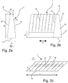
- Figs 6a and 6b show two different cross-sectional perspective views along the line VI-VI in Fig. 5 , where a roof tile 6 has been arranged on top of the load-bearing structure 3 and the sealing member 1 so that the sealing member has been compressed under its weight.
- Fig. 6a the space underneath the roof tile 6 is larger due to the curvature of the tile and the sealing member 1 has remained substantially in its original shape.
- Fig. 6b on the other hand the tile 6 curves downwards towards flashing member 43 and has therefore compressed the sealing member 1 almost entirely.
- Fig. 7 is a cross-sectional perspective view along the line VII-VII in Fig. 5 .
- the tile 6 is here kept at a distance above the top flashing member 42 by resting on a tile support rail 46 and the sealing member 1 is therefore less compressed than in Fig. 6b .
- the sealing member will be even less compresses at other sections, where the tile curves upwards towards the exterior.
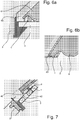
- a sealing member 1 with slit and/or weakening section planes 16 arranged at an angle ⁇ of 45 degrees is shown on a side flashing member 43 in Fig. 8 .
- the end of the sealing member is cut in the same angle as the slits and/or weakening sections and has been arranged on the flashing member so that the end part 19, which is of a non-constant cross-sectional shape and delimited by the imaginary broken lines in Fig. 8 , projects over the end of the flashing member. This allows the end part 19 to project over the edge of another flashing member and provide an overlap with a similar sealing member on an adjacent flashing member (not shown).
- sealing member 1 end at level with the end of the flashing member 43 and instead let a sealing member on the adjacent flashing project upwards to provide the overlap, or to allow only half of the triangular end part 19 on both sealing members to project so that they both contribute to an overlap.
- Fig. 9 the upper right-hand corner of a roof window frame 2 is shown mounted in an inclined load-bearing structure 3 with flashing members 42, 43, 46.
- Sealing members 1 are attached to the top flashing member 43 and the side flashing member 43 and a roofing of transparent undulated plastic tiles 6 have been laid on top of them.
- the sealing members used in this case are with slits arranged at an angle ⁇ of 75 degrees to the length direction, i.e. close to perpendicular to the length direction.
- the sealing member 1 on the top flashing member 42 has been compressed in an undulated pattern corresponding to the curvature of the roofing material 6.
- the slits have slightly opened at the exterior surface thereby allowing the sealing member to easily adapt to the shape of the tiles, but the angling of the slits ensure that the sealing remains substantially intact.
- the sealing member extending along the side flashing member 43 has been made extra long so that it also extends over the top flashing member 42 up to the level of the sealing member extending horizontally thereon.
- the top flashing member 42 would be provided with a sealing member extending in continuation of the sealing member on the side flashing member 43, possibly a single sealing member extending horizontally and then being bent over 90 degrees to come down along one or both sides towards the side flashing member(s) as shown in Fig. 5 .
- the compression of the sections of the sealing member 1 underneath the uppermost part of each tile 6 has resulted in the exterior part of the sealing member 1 not only being compressed but also having tilted in direction away from the window frame 2.
- the angle ⁇ may be adjusted, but as the tilting is at least partly caused by the sealing member sliding over the surface of the roofing material during compression, it is also possible to increase friction between the roofing material and the sealing member. This may be done by a surface treatment of the sealing member, but will easily be achieved by providing the exterior surface as a cut surface as described above with reference to Figs 3d, 3e , 4d and 4e .
Landscapes
- Engineering & Computer Science (AREA)
- Architecture (AREA)
- Civil Engineering (AREA)
- Structural Engineering (AREA)
- Physics & Mathematics (AREA)
- Electromagnetism (AREA)
- Roof Covering Using Slabs Or Stiff Sheets (AREA)
- Building Environments (AREA)
Claims (13)
- Kit de solin destiné à être utilisé dans l'installation d'une structure de pénétration de toit dans une surface de toit inclinée, comprenant
une pluralité d'éléments de solin (41, 42, 43, 44) conçus pour être disposés le long de côtés supérieur, inférieur et latéraux d'une structure de pénétration de toit, par exemple une fenêtre de toit (2), chaque élément de solin comportant un côté extérieur conçu pour faire face à l'extérieur d'un bâtiment dans l'état monté et un côté intérieur conçu pour faire face à l'intérieur du bâtiment dans l'état monté, et chaque élément de solin incluant une première patte conçue pour reposer sensiblement dans le plan du toit entre une structure porteuse de charge (3) et un matériau de couverture (6) et une seconde patte s'étendant selon un certain angle par rapport à la première patte et conçue pour reposer sensiblement parallèlement à un côté extérieur de la structure de pénétration de toit se projetant par-dessus la structure porteuse de charge, et
au moins un élément d'étanchéité (1) comprenant une surface extérieure (12) conçue pour entrer en contact avec le matériau de couverture (6), une surface intérieure (11) conçue pour être fixée à l'élément de solin et deux surfaces latérales (13) s'étendant entre la surface extérieure et la surface intérieure, ledit élément d'étanchéité présentant une direction de hauteur s'étendant de la surface intérieure à la surface extérieure, une direction de longueur (L) s'étendant parallèlement à la surface extérieure, à la surface intérieure et aux surfaces latérales, et une direction de largeur s'étendant entre les deux surfaces latérales perpendiculairement à la direction de hauteur et à la direction de longueur, dans lequel l'élément d'étanchéité est fait en un matériau compressible et des fentes et/ou des sections d'affaiblissement (16) s'étendent dans l'élément d'étanchéité depuis la surface extérieure en direction de la surface intérieure, chaque fente et/ou section d'affaiblissement s'étendant d'une surface latérale à l'autre surface latérale, dans lequel les fentes et/ou sections d'affaiblissement s'étendent dans des plans parallèles, chaque plan étant sensiblement parallèle à la direction de hauteur et s'étendant selon un angle (α) de 15 à 75 degrés dans la direction de longueur, de préférence selon un angle de 30 à 60 degrés dans la direction de longueur, plus préférablement selon un angle de 45 degrés dans la direction de longueur, ledit élément d'étanchéité étant fixé au côté extérieur d'au moins un élément de solin ou conçu pour être fixé au côté extérieur d'au moins un élément de solin pendant l'installation du kit de solin afin qu'il puisse être situé entre un élément de solin et un matériau de couverture dans un état monté du kit de solin. - Kit de solin selon la revendication 1, caractérisé en ce qu'il comprend un élément de solin supérieur (42), un élément de solin inférieur (41) et deux éléments de solin latéraux (43, 44) conçus pour être disposés respectivement le long du sommet, du bas et des côtés de la structure de pénétration de toit (2), et en ce que ledit au moins un élément d'étanchéité (1) se trouve sur deux ou plus de ces éléments de solin.
- Kit de solin selon une ou plusieurs des revendications précédentes, caractérisé en ce que les fentes et/ou sections d'affaiblissement (16) s'étendent sur au moins la moitié de la hauteur (H) de l'élément d'étanchéité (1).
- Kit de solin selon une ou plusieurs des revendications précédentes, caractérisé en ce qu'une partie intérieure (14) de l'élément d'étanchéité (1) la plus proche de la surface intérieure (11) ne comporte pas de fente ou section d'affaiblissement (16).
- Kit de solin selon une ou plusieurs des revendications précédentes, caractérisé en ce la hauteur (HI) de la partie intérieure (14) de l'élément d'étanchéité (1) constitue au moins 1/5e de la hauteur (H) de l'élément d'étanchéité (1).
- Kit de solin selon une ou plusieurs des revendications précédentes, caractérisé en ce que l'élément d'étanchéité (1) présente une hauteur (H) dans la direction de hauteur de 40 à 100 mm, de préférence de 50 à 80 mm, plus préférablement de 60 à 75 mm et/ou en ce que la distance (D) dans la direction de longueur (L) entre des fentes et/ou sections d'affaiblissement voisines (16) est de 5 à 40 mm, de préférence de 5 à 30 mm, plus préférablement de 10 à 20 mm.
- Kit de solin selon une ou plusieurs des revendications précédentes, caractérisé en ce que la largeur (WI, WE) de l'élément d'étanchéité (1) est plus petite au niveau de la surface extérieure (12) qu'au niveau de la surface intérieure (11).
- Kit de solin selon les revendications 4 et 7, caractérisé en ce que la largeur (WI) de la partie intérieure (14) de l'élément d'étanchéité (1) est sensiblement constante sur sa hauteur (HI) et en ce que la largeur de la partie extérieure restante (15) de l'élément d'étanchéité diminue en continu en direction de la surface extérieure (12).
- Kit de solin selon une ou plusieurs des revendications précédentes, caractérisé en ce que l'élément d'étanchéité (1) est réalisé par extrusion ou par un processus continu similaire et est coupé à la longueur avant utilisation.
- Kit de solin selon une ou plusieurs des revendications précédentes, caractérisé en ce que l'élément d'étanchéité (1) est intégré à un autre élément d'étanchéité et en ce que la surface extérieure (12) est une surface découpée où l'élément d'étanchéité était à l'origine relié à l'autre élément d'étanchéité.
- Kit de solin selon une ou plusieurs des revendications précédentes, caractérisé en ce que l'élément d'étanchéité (1) est réalisé en un matériau élastique, de préférence un polymère expansé tel que le polyéthylène, le polyéther ou le polyester.
- Kit de solin selon une ou plusieurs des revendications précédentes, dans lequel l'élément d'étanchéité (1) comprend en outre un moyen de fixation destiné à fixer l'élément d'étanchéité à un élément de solin (41, 42, 43, 44), ledit moyen de fixation étant de préférence choisi dans le groupe constitué des : adhésifs, rubans à double face, dispositifs de fixation de type à fermeture autogrippante, supports, évidements ou moyens d'interverrouillage similaires correspondant aux éléments sur l'élément de solin.
- Procédé de protection contre les intempéries du joint entre un toit d'un bâtiment et une structure de pénétration de toit (2), comprenant les étapes suivantes (non nécessairement dans l'ordre) :la disposition d'au moins un élément de solin (41, 42, 43, 44) sur une structure porteuse de charge (3) du toit, un côté extérieur faisant face à l'extérieur du bâtiment et un côté intérieur faisant face à l'intérieur du bâtiment, et une première patte reposant sensiblement dans le plan du toit entre une structure porteuse de charge et un matériau de couverture (6) et une seconde patte s'étendant selon un certain angle par rapport à la première patte et reposant sensiblement parallèlement à un côté extérieur de la structure de pénétration de toit (2) se projetant par-dessus la structure porteuse de charge,la disposition d'un élément d'étanchéité (1) sur l'au moins un élément de solin (41, 42, 43, 44) comportant une surface intérieure (11) fixée à l'élément de solin, ledit élément d'étanchéité comportant en outre deux surfaces latérales (13) s'étendant entre la surface intérieure et une surface extérieure (12) opposée à la surface intérieure, une direction de hauteur s'étendant de la surface intérieure à la surface extérieure, une direction de longueur (L) s'étendant parallèlement à la surface extérieure, à la surface intérieure et aux surfaces latérales, et une direction de largeur s'étendant entre les deux surfaces latérales perpendiculairement à la direction de hauteur et à la direction de longueur, et dans lequel des fentes et/ou sections d'affaiblissement (16) s'étendent dans l'élément d'étanchéité à partir de la surface extérieure vers la surface intérieure, chaque fente et/ou section d'affaiblissement s'étendant d'une surface latérale à l'autre surface latérale, et dans lequel les fentes et/ou sections d'affaiblissement s'étendent dans des plans parallèles, chaque plan étant sensiblement parallèle à la direction de hauteur et s'étendant selon un angle (α) de 15 à 75 degrés dans la direction de longueur, de préférence selon un angle de 30 à 60 degrés dans la direction de longueur, plus préférablement selon un angle de 45 degrés dans la direction de longueur,la disposition d'un matériau de couverture (6) sur la structure porteuse de charge (3) de sorte que la première patte de l'élément de solin (41, 42, 43, 44) se projette sous le matériau de couverture (6) dans l'état monté et de sorte que le matériau de couverture repose sur l'élément d'étanchéité (1) et comprime une ou plusieurs sections de l'élément d'étanchéité.
Priority Applications (1)
| Application Number | Priority Date | Filing Date | Title |
|---|---|---|---|
| PL16801960T PL3380684T3 (pl) | 2015-11-24 | 2016-11-22 | Zestaw obróbki blacharskiej zawierający człon uszczelniający do użycia pomiędzy członem obróbki blacharskiej i materiałem pokrycia dachowego oraz sposób zabezpieczenia przed warunkami atmosferycznymi połączenia pomiędzy dachem budynku a konstrukcją przenikającą przez dach |
Applications Claiming Priority (2)
| Application Number | Priority Date | Filing Date | Title |
|---|---|---|---|
| DKPA201570754A DK179229B1 (en) | 2015-11-24 | 2015-11-24 | A sealing member for use between a flashing member and a roofing material, a flashing kit including such a sealing member, and a method for weather proofing the joint between a roof of a building and a roof penetrating structure |
| PCT/DK2016/050381 WO2017088882A1 (fr) | 2015-11-24 | 2016-11-22 | Élément d'étanchéité destiné à une utilisation entre un élément de solin et un matériau de couverture, kit de solin pourvu de cet élément d'étanchéité, et procédé de protection du joint contre les intempéries entre un toit d'un bâtiment et une structure de pénétration de toit |
Publications (2)
| Publication Number | Publication Date |
|---|---|
| EP3380684A1 EP3380684A1 (fr) | 2018-10-03 |
| EP3380684B1 true EP3380684B1 (fr) | 2020-04-15 |
Family
ID=58763967
Family Applications (1)
| Application Number | Title | Priority Date | Filing Date |
|---|---|---|---|
| EP16801960.2A Active EP3380684B1 (fr) | 2015-11-24 | 2016-11-22 | Kit de solin pourvu d'un élément d'étanchéité destiné à une utilisation entre un élément de solin et un matériau de couverture, et procédé de protection du joint contre les intempéries entre un toit d'un bâtiment et une structure de pénétration de toit |
Country Status (11)
| Country | Link |
|---|---|
| US (1) | US10443231B2 (fr) |
| EP (1) | EP3380684B1 (fr) |
| JP (1) | JP3223285U (fr) |
| CN (1) | CN108431342B (fr) |
| AU (1) | AU2016359632B2 (fr) |
| CA (1) | CA3006216C (fr) |
| DK (1) | DK179229B1 (fr) |
| EA (1) | EA037873B1 (fr) |
| HU (1) | HUE049889T2 (fr) |
| PL (1) | PL3380684T3 (fr) |
| WO (1) | WO2017088882A1 (fr) |
Families Citing this family (4)
| Publication number | Priority date | Publication date | Assignee | Title |
|---|---|---|---|---|
| DK180877B1 (en) * | 2019-09-25 | 2022-06-09 | Vkr Holding As | Flashing Assembly for a roof Penetrating Structure |
| DK180960B1 (en) * | 2019-12-05 | 2022-08-11 | Vkr Holding As | A sealing gasket for use between flashing members, a flashing arrangement for a roof window including at least two flashing members and at least one sealing gasket, and method of sealing a gap between flashing members for a roof window |
| US11473296B2 (en) * | 2020-10-22 | 2022-10-18 | Schul International Co., Llc | Field impregnation expansion joint seal system and method of use |
| DK181327B1 (en) * | 2021-01-12 | 2023-08-15 | Vkr Holding As | A bottom flashing element for a roof penetrating structure, a flashing assembly, and a roof window mounted in an inclined roof |
Citations (1)
| Publication number | Priority date | Publication date | Assignee | Title |
|---|---|---|---|---|
| EP0320343A1 (fr) * | 1987-12-04 | 1989-06-14 | Michel Goubaud | Closoir, en particulier closoir de faitage, à bande(s) d'étanchéité élastiquement déformable(s) |
Family Cites Families (23)
| Publication number | Priority date | Publication date | Assignee | Title |
|---|---|---|---|---|
| DE1434154A1 (de) * | 1960-12-22 | 1969-01-23 | Kann V Rasmussen & Co | Eindeckrahmen fuer schraeg in der Dachflaeche liegende Fenster |
| DE2503519A1 (de) * | 1975-01-29 | 1976-08-05 | Beijer Gmbh | Eindeckrahmen zur dichtenden verbindung der dachhaut mit einem dachwohnraumfenster |
| US4110881A (en) * | 1976-12-10 | 1978-09-05 | Thompson M Stafford | Resilient article and method of manufacture |
| DE8337220U1 (de) * | 1983-12-24 | 1984-04-12 | Handel & Mack GmbH & Co KG, 7315 Weilheim | Eindeckrahmen |
| US4848051A (en) * | 1988-04-21 | 1989-07-18 | Henergy Enterprises Limited Partnership | Glass glazed standing seam skylight |
| US5053266A (en) * | 1988-12-23 | 1991-10-01 | Dovetail Building Products Limited | Ventilation tile with pliable edge areas |
| DK167455B1 (da) * | 1991-09-26 | 1993-11-01 | Rasmussen Kann Ind As | Blyfrit inddaekningsmateriale |
| DK123292A (da) * | 1992-10-07 | 1994-04-08 | Rasmussen Kann Ind As | Tilslutningskrave til tætnende tilslutning af et undertag til et ovenlysvindue eller et andet tagindbygningselement og fremgangsmåde til fremstilling heraf |
| DK44494A (da) * | 1994-04-18 | 1995-10-19 | Rasmussen Kann Ind As | Inddækning til tagelementer |
| NL1008048C2 (nl) * | 1998-01-16 | 1999-07-19 | Ubbink Nederland Bv | Verholen goot. |
| NL1009317C2 (nl) * | 1998-06-04 | 1999-12-07 | Redland Dakprod Bv | Schuin dak met dakraam en indekdeel. |
| ATE384175T1 (de) | 2001-12-03 | 2008-02-15 | Vkr Holding As | Element zur bereitstellung eines dichtungsübergangs in verbindung mit gebäudeteilen |
| ATE528458T1 (de) * | 2002-03-07 | 2011-10-15 | Vkr Holding As | Anschlussausrüstung |
| US6598356B1 (en) * | 2002-06-20 | 2003-07-29 | Cor-A-Vent, Inc. | Insulated roofing system having a form-fitting compressible seal and ventilation |
| NL1026979C2 (nl) * | 2004-09-06 | 2006-03-07 | M J Hendrix | Dakkapel en werkwijze voor het vervaardigen van een dergelijke dakkapel. |
| GB2430943B (en) * | 2005-09-21 | 2010-08-04 | Viridian Concepts Ltd | Roof flashing connections comprising resilient member |
| EP1959064B1 (fr) * | 2007-02-14 | 2009-04-22 | ISO-Chemie GmbH | Bande d'étanchéité pouvant se repositionner |
| PL1983121T3 (pl) * | 2007-04-17 | 2014-04-30 | Iso Chemie Gmbh | Impregnowana taśma uszczelniająca z wcięciami |
| US20090064605A1 (en) * | 2007-09-07 | 2009-03-12 | Hoffman David J | Dock seal with partially sliced foam core |
| US20100024321A1 (en) * | 2008-08-01 | 2010-02-04 | Airmark, Inc. | Shim having a plurality of snap lines |
| DK2428632T3 (da) * | 2010-09-08 | 2014-04-07 | Iso Chemie Gmbh | Tætningsbånd af blødt skumstof |
| DE202014100478U1 (de) * | 2014-02-04 | 2015-05-05 | Pinta Abdichtung Gmbh | Dichtband |
| US10072423B2 (en) * | 2016-01-08 | 2018-09-11 | Atlas Bolt & Screw Company Llc | Compressible foam closure for metal roofs |
-
2015
- 2015-11-24 DK DKPA201570754A patent/DK179229B1/en active
-
2016
- 2016-11-22 EA EA201800332A patent/EA037873B1/ru unknown
- 2016-11-22 CA CA3006216A patent/CA3006216C/fr active Active
- 2016-11-22 US US15/777,921 patent/US10443231B2/en active Active
- 2016-11-22 PL PL16801960T patent/PL3380684T3/pl unknown
- 2016-11-22 HU HUE16801960A patent/HUE049889T2/hu unknown
- 2016-11-22 WO PCT/DK2016/050381 patent/WO2017088882A1/fr active Application Filing
- 2016-11-22 CN CN201680077326.1A patent/CN108431342B/zh active Active
- 2016-11-22 AU AU2016359632A patent/AU2016359632B2/en active Active
- 2016-11-22 EP EP16801960.2A patent/EP3380684B1/fr active Active
- 2016-11-22 JP JP2018600063U patent/JP3223285U/ja active Active
Patent Citations (1)
| Publication number | Priority date | Publication date | Assignee | Title |
|---|---|---|---|---|
| EP0320343A1 (fr) * | 1987-12-04 | 1989-06-14 | Michel Goubaud | Closoir, en particulier closoir de faitage, à bande(s) d'étanchéité élastiquement déformable(s) |
Also Published As
| Publication number | Publication date |
|---|---|
| DK179229B1 (en) | 2018-02-19 |
| JP3223285U (ja) | 2019-10-03 |
| PL3380684T3 (pl) | 2020-09-21 |
| AU2016359632A1 (en) | 2018-07-05 |
| EA201800332A1 (ru) | 2019-03-29 |
| CN108431342A (zh) | 2018-08-21 |
| US10443231B2 (en) | 2019-10-15 |
| CA3006216A1 (fr) | 2017-06-01 |
| US20180347180A1 (en) | 2018-12-06 |
| AU2016359632B2 (en) | 2021-11-04 |
| WO2017088882A1 (fr) | 2017-06-01 |
| CA3006216C (fr) | 2022-05-17 |
| EA037873B1 (ru) | 2021-05-31 |
| EP3380684A1 (fr) | 2018-10-03 |
| HUE049889T2 (hu) | 2020-10-28 |
| CN108431342B (zh) | 2020-06-16 |
| WO2017088882A9 (fr) | 2018-02-22 |
| DK201570754A1 (en) | 2017-06-12 |
Similar Documents
| Publication | Publication Date | Title |
|---|---|---|
| EP3380684B1 (fr) | Kit de solin pourvu d'un élément d'étanchéité destiné à une utilisation entre un élément de solin et un matériau de couverture, et procédé de protection du joint contre les intempéries entre un toit d'un bâtiment et une structure de pénétration de toit | |
| CA2136314C (fr) | Dispositif d'etancheite pour fenetres, notamment pour lanterneaux | |
| EP2466032B1 (fr) | Élément isolant avec deux éléments du materiaux différents et procédé pour isoler une fenêtre dans une structure de toit inclinée avec cet élément | |
| US20070107358A1 (en) | Concrete tile system and method of manufacture | |
| EP3263797B1 (fr) | Fenêtre de toit et structure de toit en pente | |
| US20030159379A1 (en) | Balcony drainage apparatus and method of using the same | |
| EP1485547B1 (fr) | Necessaire de solin | |
| HU204913B (en) | Lower shell plating from heat-insulating roofing support plates | |
| EP0397278A1 (fr) | Panneau | |
| US20080289290A1 (en) | Roofing System for Buildings | |
| EP0002587B1 (fr) | Recouvrement de noue et toiture avec une telle noue | |
| DE10201528C1 (de) | Gratanschlußelement | |
| EP3683375A1 (fr) | Cadre d'isolation comprenant une zone de déformation transitoire | |
| EP0872605A2 (fr) | Elément de construction isolant | |
| EP2740854A1 (fr) | Construction de solin isolé | |
| CA2516483A1 (fr) | Garniture de bout pour panneaux de toiture | |
| GB2621532A (en) | A roof waterproofing element | |
| JP4263272B2 (ja) | 寄せ棟用窯業系屋根材の施工方法 |
Legal Events
| Date | Code | Title | Description |
|---|---|---|---|
| STAA | Information on the status of an ep patent application or granted ep patent |
Free format text: STATUS: UNKNOWN |
|
| STAA | Information on the status of an ep patent application or granted ep patent |
Free format text: STATUS: THE INTERNATIONAL PUBLICATION HAS BEEN MADE |
|
| PUAI | Public reference made under article 153(3) epc to a published international application that has entered the european phase |
Free format text: ORIGINAL CODE: 0009012 |
|
| STAA | Information on the status of an ep patent application or granted ep patent |
Free format text: STATUS: REQUEST FOR EXAMINATION WAS MADE |
|
| 17P | Request for examination filed |
Effective date: 20180622 |
|
| AK | Designated contracting states |
Kind code of ref document: A1 Designated state(s): AL AT BE BG CH CY CZ DE DK EE ES FI FR GB GR HR HU IE IS IT LI LT LU LV MC MK MT NL NO PL PT RO RS SE SI SK SM TR |
|
| AX | Request for extension of the european patent |
Extension state: BA ME |
|
| DAV | Request for validation of the european patent (deleted) | ||
| DAX | Request for extension of the european patent (deleted) | ||
| STAA | Information on the status of an ep patent application or granted ep patent |
Free format text: STATUS: EXAMINATION IS IN PROGRESS |
|
| 17Q | First examination report despatched |
Effective date: 20190415 |
|
| GRAP | Despatch of communication of intention to grant a patent |
Free format text: ORIGINAL CODE: EPIDOSNIGR1 |
|
| STAA | Information on the status of an ep patent application or granted ep patent |
Free format text: STATUS: GRANT OF PATENT IS INTENDED |
|
| INTG | Intention to grant announced |
Effective date: 20191111 |
|
| GRAS | Grant fee paid |
Free format text: ORIGINAL CODE: EPIDOSNIGR3 |
|
| GRAA | (expected) grant |
Free format text: ORIGINAL CODE: 0009210 |
|
| STAA | Information on the status of an ep patent application or granted ep patent |
Free format text: STATUS: THE PATENT HAS BEEN GRANTED |
|
| AK | Designated contracting states |
Kind code of ref document: B1 Designated state(s): AL AT BE BG CH CY CZ DE DK EE ES FI FR GB GR HR HU IE IS IT LI LT LU LV MC MK MT NL NO PL PT RO RS SE SI SK SM TR |
|
| REG | Reference to a national code |
Ref country code: CH Ref legal event code: EP |
|
| REG | Reference to a national code |
Ref country code: DE Ref legal event code: R096 Ref document number: 602016034178 Country of ref document: DE |
|
| REG | Reference to a national code |
Ref country code: IE Ref legal event code: FG4D |
|
| REG | Reference to a national code |
Ref country code: AT Ref legal event code: REF Ref document number: 1257449 Country of ref document: AT Kind code of ref document: T Effective date: 20200515 |
|
| REG | Reference to a national code |
Ref country code: NL Ref legal event code: FP |
|
| REG | Reference to a national code |
Ref country code: SK Ref legal event code: T3 Ref document number: E 34573 Country of ref document: SK |
|
| REG | Reference to a national code |
Ref country code: LT Ref legal event code: MG4D |
|
| REG | Reference to a national code |
Ref country code: HU Ref legal event code: AG4A Ref document number: E049889 Country of ref document: HU |
|
| PG25 | Lapsed in a contracting state [announced via postgrant information from national office to epo] |
Ref country code: IS Free format text: LAPSE BECAUSE OF FAILURE TO SUBMIT A TRANSLATION OF THE DESCRIPTION OR TO PAY THE FEE WITHIN THE PRESCRIBED TIME-LIMIT Effective date: 20200815 Ref country code: SE Free format text: LAPSE BECAUSE OF FAILURE TO SUBMIT A TRANSLATION OF THE DESCRIPTION OR TO PAY THE FEE WITHIN THE PRESCRIBED TIME-LIMIT Effective date: 20200415 Ref country code: FI Free format text: LAPSE BECAUSE OF FAILURE TO SUBMIT A TRANSLATION OF THE DESCRIPTION OR TO PAY THE FEE WITHIN THE PRESCRIBED TIME-LIMIT Effective date: 20200415 Ref country code: GR Free format text: LAPSE BECAUSE OF FAILURE TO SUBMIT A TRANSLATION OF THE DESCRIPTION OR TO PAY THE FEE WITHIN THE PRESCRIBED TIME-LIMIT Effective date: 20200716 Ref country code: PT Free format text: LAPSE BECAUSE OF FAILURE TO SUBMIT A TRANSLATION OF THE DESCRIPTION OR TO PAY THE FEE WITHIN THE PRESCRIBED TIME-LIMIT Effective date: 20200817 Ref country code: NO Free format text: LAPSE BECAUSE OF FAILURE TO SUBMIT A TRANSLATION OF THE DESCRIPTION OR TO PAY THE FEE WITHIN THE PRESCRIBED TIME-LIMIT Effective date: 20200715 Ref country code: LT Free format text: LAPSE BECAUSE OF FAILURE TO SUBMIT A TRANSLATION OF THE DESCRIPTION OR TO PAY THE FEE WITHIN THE PRESCRIBED TIME-LIMIT Effective date: 20200415 |
|
| PG25 | Lapsed in a contracting state [announced via postgrant information from national office to epo] |
Ref country code: RS Free format text: LAPSE BECAUSE OF FAILURE TO SUBMIT A TRANSLATION OF THE DESCRIPTION OR TO PAY THE FEE WITHIN THE PRESCRIBED TIME-LIMIT Effective date: 20200415 Ref country code: BG Free format text: LAPSE BECAUSE OF FAILURE TO SUBMIT A TRANSLATION OF THE DESCRIPTION OR TO PAY THE FEE WITHIN THE PRESCRIBED TIME-LIMIT Effective date: 20200715 Ref country code: HR Free format text: LAPSE BECAUSE OF FAILURE TO SUBMIT A TRANSLATION OF THE DESCRIPTION OR TO PAY THE FEE WITHIN THE PRESCRIBED TIME-LIMIT Effective date: 20200415 Ref country code: LV Free format text: LAPSE BECAUSE OF FAILURE TO SUBMIT A TRANSLATION OF THE DESCRIPTION OR TO PAY THE FEE WITHIN THE PRESCRIBED TIME-LIMIT Effective date: 20200415 |
|
| PG25 | Lapsed in a contracting state [announced via postgrant information from national office to epo] |
Ref country code: AL Free format text: LAPSE BECAUSE OF FAILURE TO SUBMIT A TRANSLATION OF THE DESCRIPTION OR TO PAY THE FEE WITHIN THE PRESCRIBED TIME-LIMIT Effective date: 20200415 |
|
| REG | Reference to a national code |
Ref country code: DE Ref legal event code: R097 Ref document number: 602016034178 Country of ref document: DE |
|
| PG25 | Lapsed in a contracting state [announced via postgrant information from national office to epo] |
Ref country code: SM Free format text: LAPSE BECAUSE OF FAILURE TO SUBMIT A TRANSLATION OF THE DESCRIPTION OR TO PAY THE FEE WITHIN THE PRESCRIBED TIME-LIMIT Effective date: 20200415 Ref country code: RO Free format text: LAPSE BECAUSE OF FAILURE TO SUBMIT A TRANSLATION OF THE DESCRIPTION OR TO PAY THE FEE WITHIN THE PRESCRIBED TIME-LIMIT Effective date: 20200415 Ref country code: DK Free format text: LAPSE BECAUSE OF FAILURE TO SUBMIT A TRANSLATION OF THE DESCRIPTION OR TO PAY THE FEE WITHIN THE PRESCRIBED TIME-LIMIT Effective date: 20200415 Ref country code: EE Free format text: LAPSE BECAUSE OF FAILURE TO SUBMIT A TRANSLATION OF THE DESCRIPTION OR TO PAY THE FEE WITHIN THE PRESCRIBED TIME-LIMIT Effective date: 20200415 Ref country code: ES Free format text: LAPSE BECAUSE OF FAILURE TO SUBMIT A TRANSLATION OF THE DESCRIPTION OR TO PAY THE FEE WITHIN THE PRESCRIBED TIME-LIMIT Effective date: 20200415 |
|
| PLBE | No opposition filed within time limit |
Free format text: ORIGINAL CODE: 0009261 |
|
| STAA | Information on the status of an ep patent application or granted ep patent |
Free format text: STATUS: NO OPPOSITION FILED WITHIN TIME LIMIT |
|
| 26N | No opposition filed |
Effective date: 20210118 |
|
| PG25 | Lapsed in a contracting state [announced via postgrant information from national office to epo] |
Ref country code: SI Free format text: LAPSE BECAUSE OF FAILURE TO SUBMIT A TRANSLATION OF THE DESCRIPTION OR TO PAY THE FEE WITHIN THE PRESCRIBED TIME-LIMIT Effective date: 20200415 |
|
| PG25 | Lapsed in a contracting state [announced via postgrant information from national office to epo] |
Ref country code: MC Free format text: LAPSE BECAUSE OF FAILURE TO SUBMIT A TRANSLATION OF THE DESCRIPTION OR TO PAY THE FEE WITHIN THE PRESCRIBED TIME-LIMIT Effective date: 20200415 |
|
| PG25 | Lapsed in a contracting state [announced via postgrant information from national office to epo] |
Ref country code: LU Free format text: LAPSE BECAUSE OF NON-PAYMENT OF DUE FEES Effective date: 20201122 |
|
| PG25 | Lapsed in a contracting state [announced via postgrant information from national office to epo] |
Ref country code: IE Free format text: LAPSE BECAUSE OF NON-PAYMENT OF DUE FEES Effective date: 20201122 |
|
| REG | Reference to a national code |
Ref country code: AT Ref legal event code: UEP Ref document number: 1257449 Country of ref document: AT Kind code of ref document: T Effective date: 20200415 |
|
| PG25 | Lapsed in a contracting state [announced via postgrant information from national office to epo] |
Ref country code: TR Free format text: LAPSE BECAUSE OF FAILURE TO SUBMIT A TRANSLATION OF THE DESCRIPTION OR TO PAY THE FEE WITHIN THE PRESCRIBED TIME-LIMIT Effective date: 20200415 Ref country code: MT Free format text: LAPSE BECAUSE OF FAILURE TO SUBMIT A TRANSLATION OF THE DESCRIPTION OR TO PAY THE FEE WITHIN THE PRESCRIBED TIME-LIMIT Effective date: 20200415 Ref country code: CY Free format text: LAPSE BECAUSE OF FAILURE TO SUBMIT A TRANSLATION OF THE DESCRIPTION OR TO PAY THE FEE WITHIN THE PRESCRIBED TIME-LIMIT Effective date: 20200415 |
|
| PG25 | Lapsed in a contracting state [announced via postgrant information from national office to epo] |
Ref country code: MK Free format text: LAPSE BECAUSE OF FAILURE TO SUBMIT A TRANSLATION OF THE DESCRIPTION OR TO PAY THE FEE WITHIN THE PRESCRIBED TIME-LIMIT Effective date: 20200415 |
|
| PGFP | Annual fee paid to national office [announced via postgrant information from national office to epo] |
Ref country code: HU Payment date: 20221022 Year of fee payment: 7 |
|
| PGFP | Annual fee paid to national office [announced via postgrant information from national office to epo] |
Ref country code: NL Payment date: 20231013 Year of fee payment: 8 |
|
| PGFP | Annual fee paid to national office [announced via postgrant information from national office to epo] |
Ref country code: SK Payment date: 20231013 Year of fee payment: 8 |
|
| PGFP | Annual fee paid to national office [announced via postgrant information from national office to epo] |
Ref country code: GB Payment date: 20231006 Year of fee payment: 8 |
|
| PGFP | Annual fee paid to national office [announced via postgrant information from national office to epo] |
Ref country code: IT Payment date: 20231010 Year of fee payment: 8 Ref country code: FR Payment date: 20231024 Year of fee payment: 8 Ref country code: DE Payment date: 20231003 Year of fee payment: 8 Ref country code: CZ Payment date: 20231026 Year of fee payment: 8 Ref country code: CH Payment date: 20231201 Year of fee payment: 8 Ref country code: AT Payment date: 20231025 Year of fee payment: 8 |
|
| PGFP | Annual fee paid to national office [announced via postgrant information from national office to epo] |
Ref country code: PL Payment date: 20231016 Year of fee payment: 8 Ref country code: BE Payment date: 20231016 Year of fee payment: 8 |