EP3380279B1 - Procede de programmation d'un effort a exercer par un robot - Google Patents
Procede de programmation d'un effort a exercer par un robot Download PDFInfo
- Publication number
- EP3380279B1 EP3380279B1 EP16798462.4A EP16798462A EP3380279B1 EP 3380279 B1 EP3380279 B1 EP 3380279B1 EP 16798462 A EP16798462 A EP 16798462A EP 3380279 B1 EP3380279 B1 EP 3380279B1
- Authority
- EP
- European Patent Office
- Prior art keywords
- force
- working end
- robot
- trajectory
- operator
- Prior art date
- Legal status (The legal status is an assumption and is not a legal conclusion. Google has not performed a legal analysis and makes no representation as to the accuracy of the status listed.)
- Active
Links
Images
Classifications
-
- B—PERFORMING OPERATIONS; TRANSPORTING
- B25—HAND TOOLS; PORTABLE POWER-DRIVEN TOOLS; MANIPULATORS
- B25J—MANIPULATORS; CHAMBERS PROVIDED WITH MANIPULATION DEVICES
- B25J9/00—Program-controlled manipulators
- B25J9/16—Program controls
- B25J9/1656—Program controls characterised by programming, planning systems for manipulators
- B25J9/1664—Program controls characterised by programming, planning systems for manipulators characterised by motion, path, trajectory planning
-
- B—PERFORMING OPERATIONS; TRANSPORTING
- B25—HAND TOOLS; PORTABLE POWER-DRIVEN TOOLS; MANIPULATORS
- B25J—MANIPULATORS; CHAMBERS PROVIDED WITH MANIPULATION DEVICES
- B25J9/00—Program-controlled manipulators
- B25J9/16—Program controls
- B25J9/1628—Program controls characterised by the control loop
- B25J9/163—Program controls characterised by the control loop learning, adaptive, model based, rule based expert control
-
- B—PERFORMING OPERATIONS; TRANSPORTING
- B25—HAND TOOLS; PORTABLE POWER-DRIVEN TOOLS; MANIPULATORS
- B25J—MANIPULATORS; CHAMBERS PROVIDED WITH MANIPULATION DEVICES
- B25J9/00—Program-controlled manipulators
- B25J9/16—Program controls
- B25J9/1656—Program controls characterised by programming, planning systems for manipulators
- B25J9/1671—Program controls characterised by programming, planning systems for manipulators characterised by simulation, either to verify existing program or to create and verify new program, CAD/CAM oriented, graphic oriented programming systems
-
- G—PHYSICS
- G05—CONTROLLING; REGULATING
- G05B—CONTROL OR REGULATING SYSTEMS IN GENERAL; FUNCTIONAL ELEMENTS OF SUCH SYSTEMS; MONITORING OR TESTING ARRANGEMENTS FOR SUCH SYSTEMS OR ELEMENTS
- G05B19/00—Program-control systems
- G05B19/02—Program-control systems electric
- G05B19/42—Recording and playback systems, i.e. in which the program is recorded from a cycle of operations, e.g. the cycle of operations being manually controlled, after which this record is played back on the same machine
- G05B19/423—Teaching successive positions by walk-through, i.e. the tool head or end effector being grasped and guided directly, with or without servo-assistance, to follow a path
-
- G—PHYSICS
- G05—CONTROLLING; REGULATING
- G05B—CONTROL OR REGULATING SYSTEMS IN GENERAL; FUNCTIONAL ELEMENTS OF SUCH SYSTEMS; MONITORING OR TESTING ARRANGEMENTS FOR SUCH SYSTEMS OR ELEMENTS
- G05B2219/00—Program-control systems
- G05B2219/30—Nc systems
- G05B2219/36—Nc in input of data, input key till input tape
- G05B2219/36489—Position and force
-
- G—PHYSICS
- G05—CONTROLLING; REGULATING
- G05B—CONTROL OR REGULATING SYSTEMS IN GENERAL; FUNCTIONAL ELEMENTS OF SUCH SYSTEMS; MONITORING OR TESTING ARRANGEMENTS FOR SUCH SYSTEMS OR ELEMENTS
- G05B2219/00—Program-control systems
- G05B2219/30—Nc systems
- G05B2219/45—Nc applications
- G05B2219/45083—Manipulators, robot
Definitions
- the present invention relates to the field of robotics and more particularly, but not exclusively, collaborative robotics.
- Such robots generally comprise an arm equipped with a motorization connected to a computer control unit which is programmed to control the motorization of the arm to move a working end of the robotic arm along a path corresponding to the task to be performed and to exert a force at the working end at predetermined points on the path corresponding to the task to be performed.
- the programming of the trajectory is usually carried out by coding or by learning.
- the first method consists in introducing, directly into the control program for the motorization of the arm, the instructions for controlling the motorization making it possible to bring the working end (commonly called effector) of the arm to points defining the trajectory desired.
- the second method is to learn waypoints by moving the end of the robot with some kind of console or joys-tick controller.
- Collaborative robots allow a method of learning by demonstration. It consists in causing the working end to be moved by an operator along the desired path while the successive positions of the arm are memorized either punctually or continuously.
- US5880956 shows a learning method.
- the programming of the force that the motorized arm must exert is always carried out by coding and consists in entering, directly in the control program of the motorization of the arm, the instructions for controlling the motorization allowing the working end of the arm. exert the desired force at each point defining the desired trajectory.
- An object of the invention is to simplify the programming of robots in effort.
- the trajectory may have been pre-programmed by any of the known methods.
- movement of the working end of the robot on the part of the preprogrammed trajectory is meant the movement of said working end along this part or on passage points defining this trajectory.
- the programming of the force to be produced by the working end of the robot is thus directly carried out by the operator exerting on the working end or an element integral with the latter a force corresponding to the force to be carried out.
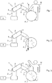
- the method of the invention is implemented by means of a robotic arm 1 comprising a plurality of segments 2, including a working end, connected in pairs by at least one articulation 3 provided with a motor connected to a control unit 4 of the robotic arm 1.
- the control unit 4 is arranged to be able to control the motors of the robotic arm 1.
- the task to be carried out here is the polishing of a part P represented here by a sphere using a polishing tool 5 moved along a path t by applying a force F.
- the programming of the robotic arm is carried out by executing a computer program for configuring the robotic arm 1: this program is executed either directly by the control unit 4 or by a computer connected to the control unit 4.
- the working end can advantageously be equipped with the tool 5 during the two programming phases and the verification phase.
- the part P to be polished can advantageously be present.
- the programming phase of the trajectory t can advantageously be carried out by causing the operator M to move the working end of the robotic arm 1 along the desired trajectory t, or on waypoints, and by memorizing working end positions.
- the positions can be stored on command from the operator M or continuously over the entire trajectory t.
- the user stops the working end of the robotic arm 1 and controls the memorization of the position by acting on an input interface, such as a remote control or a button on the robot, connected to the control unit.
- control 4 (or, as a variant, to an external control member such as a computer).
- the operator launches on the control unit 4 a session for programming the trajectory (for example by pressing a predetermined button on a remote control) and the control unit 4 continuously records the positions of the working end until the operator announces the end of the session (for example by pressing a predetermined button on a remote control).
- the programming phase of the force F is carried out by causing the control unit 4 to move the working end of the robotic arm 1 along the programmed path t, or on the passage points learned only.
- the motorization of the robotic arm 1 is controlled to keep the working end in position on the path t without a force setpoint.
- the operator M exerts on the working end a force f which is opposed to the force F to be applied during the task.
- the opposite force f is applied by the hand of the operator M which is in direct contact with the working end of the robotic arm 1.
- the force f is of intensity equal to the force F.
- the force F is then determined from the resistant force exerted by the robotic arm 1 to maintain the working end on the path t, or on the passage points.
- the resistive force is determined by the control unit 4 from the electric current supplying the motorization of the robotic arm 1 necessary to maintain the working end in the position.
- the resistive force is determined by the control unit from a measurement of a force sensor arranged on the working end.
- the force F thus determined is stored in relation to the position of the working end during the exercise of the opposite effort f.
- the final, recommended but optional, step of checking the programming here consists of controlling the robotic arm 1 to move the working end along the path t while the operator M is in contact with the working end so that the operator feels the force applied by the robotic arm 1.
- the opposing force f is exerted by means of a mechanical link 6, such as a cable or a rod mounted on a ball joint, having one end connected to the working end and an opposite end held by the operator M.
- a mechanical link 6 such as a cable or a rod mounted on a ball joint
- This mode of exercise of the opposite force f is advantageous because the direction of the tension of the mechanical link makes it possible to visualize the direction of the opposite force f.
- the opposite force f is exerted by means of an elastic element connected to the working end.
- the elastic element can be an elastic flexible link or a rigid element connected to the working end by an elastic member such as a dynamometer. This mode of exercise of the opposite force f is advantageous because it allows in addition to the direction of the tension of the link, to visualize the intensity of the opposing effort f.
- the invention is described in relation to a robotic arm of the series type, the invention is applicable to all types of robot and machine that can be controlled in terms of force.
- the invention thus remains applicable to the case of parallel robots, or in the case of more than two segments connected to one another.
- the operator can apply the opposite force by means of a manipulation handle fixed to the working end of the robotic arm 1.
- the resistive force is then preferably determined from a measurement of a sensor of. force placed on the manipulation handle of the working end of the robotic arm 1.
Landscapes
- Engineering & Computer Science (AREA)
- Robotics (AREA)
- Mechanical Engineering (AREA)
- Physics & Mathematics (AREA)
- General Physics & Mathematics (AREA)
- Automation & Control Theory (AREA)
- Manipulator (AREA)
Description
- La présente invention concerne le domaine de la robotique et plus particulièrement, mais pas exclusivement, la robotique collaborative.
- Il est connu d'utiliser des robots pour effectuer des tâches dites « au contact », c'est-à-dire des tâches au cours desquelles les robots sont en contact avec un élément de leur environnement soit directement soit par l'intermédiaire d'un outil ou d'une pièce portée par les robots. Ces tâches comprennent des opérations de polissage, d'ébavurage, d'assemblage...
- De tels robots comprennent généralement un bras équipé d'une motorisation reliée à une unité informatique de commande qui est programmée pour commander la motorisation du bras pour déplacer une extrémité de travail du bras robotisé le long d'une trajectoire correspondant à la tâche à réaliser et pour faire exercer à l'extrémité de travail un effort en des points prédéterminés de la trajectoire correspondant à la tâche à réaliser.
- Ces robots sont donc simultanément commandables en position et en effort selon des degrés de liberté propres à la tâche.
- La programmation de la trajectoire est habituellement réalisée par codage ou par apprentissage. La première méthode consiste à introduire, directement dans le programme de commande de la motorisation du bras, les instructions de commande de la motorisation permettant d'amener l'extrémité de travail (couramment appelée effecteur) du bras en des points définissant la trajectoire souhaitée. La deuxième méthode consiste à apprendre des points de passage en déplaçant l'extrémité du robot avec un organe de commande quelconque de type console ou joys-tick.
- Les robots collaboratifs permettent une méthode d'apprentissage par démonstration. Elle consiste à faire déplacer l'extrémité de travail par un opérateur le long de la trajectoire souhaitée pendant que les positions successives du bras sont mémorisées soit ponctuellement soit en continu.
US5880956 montre une méthode d'apprentissage. - La programmation de l'effort que le bras motorisé doit exercer est toujours réalisée par codage et consiste à introduire, directement dans le programme de commande de la motorisation du bras, les instructions de commande de la motorisation permettant à l'extrémité de travail du bras d'exercer l'effort souhaité en chaque point définissant la trajectoire souhaitée.
- Un but de l'invention est de simplifier la programmation des robots en effort.
- A cet effet, on prévoit, selon l'invention, un procédé de programmation d'un effort à exercer par une extrémité de travail d'un robot le long d'au moins une partie d'une trajectoire préprogrammée de l'extrémité de travail, le procédé comprenant les étapes de :
- déplacer l'extrémité de travail du robot sur ladite au moins une partie de la trajectoire préprogrammée, la motorisation du robot étant asservie pour maintenir l'extrémité de travail en position sans consigne d'effort,
- en au moins une position au cours du déplacement, faire exercer sur l'extrémité de travail, par un opérateur, un effort qui est opposé à celui à appliquer lors de la tâche et qui a une intensité proportionnelle à celui à appliquer lors de la tâche,
- déterminer l'effort à appliquer lors de la tâche à partir de l'effort résistant exercé par le robot pour maintenir l'extrémité de travail sur la trajectoire,
- mémoriser l'effort ainsi déterminé en relation avec la position de l'extrémité de travail lors de l'exercice de l'effort opposé
- La trajectoire peut avoir été préprogrammée par l'une quelconque des méthodes connues. Par déplacement de l'extrémité de travail du robot sur la partie de trajectoire préprogrammée, on entend le déplacement de ladite extrémité de travail le long de cette partie ou sur des points de passage définissant cette trajectoire. La programmation de l'effort à réaliser par l'extrémité de travail du robot est ainsi directement effectuée par l'opérateur exerçant sur l'extrémité de travail ou un élément solidaire de celle-ci un effort correspondant à l'effort à réaliser.
- D'autres caractéristiques et avantages de l'invention ressortiront à la lecture de la description qui suit de modes de réalisation particuliers non limitatifs de l'invention.
- Il sera fait référence aux dessins annexés, parmi lesquels :
- la
figure 1 est une vue schématique illustrant la phase d'apprentissage de l'effort par le robot selon le procédé de l'invention ; - la
figure 2 est une vue schématique illustrant la réalisation de la tâche par le robot ; - la
figure 3 est une vue schématique illustrant la phase d'apprentissage de l'effort par le robot selon une variante de mise en œuvre du procédé de l'invention. - En référence aux
figures 1 et 2 , le procédé de l'invention est mis en œuvre au moyen d'un bras robotisé 1 comprenant une pluralité de segments 2, dont une extrémité de travail, reliés deux à deux par au moins une articulation 3 pourvue d'un moteur relié à une unité de commande 4 du bras robotisé 1. L'unité de commande 4 est agencée pour pouvoir commander les moteurs du bras robotisé 1. Un tel système robotisé est connu en lui-même et ne sera pas plus détaillé ici. - La tâche à réaliser est ici le polissage d'une pièce P représentée ici par une sphère en utilisant un outil de polissage 5 déplacé selon une trajectoire t en appliquant un effort F.
- La programmation du bras robotisé est réalisée par l'exécution d'un programme informatique de configuration du bras robotisé 1 : ce programme est exécuté soit directement par l'unité de commande 4 soit par un ordinateur raccordé à l'unité de commande 4.
- La programmation du bras robotisé 1 pour réaliser la tâche en question comprend les phases de :
- programmer la trajectoire t de l'extrémité de travail correspondant à la tâche à réaliser,
- programmer l'effort F à appliquer par l'extrémité de travail le long d'au moins une partie de la trajectoire t (le long de la trajectoire ou en des points de passage définissant la trajectoire),
- vérifier la programmation de la trajectoire t et de l'effort F.
- L'extrémité de travail peut avantageusement être équipée de l'outil 5 lors des deux phases de programmation et de la phase de vérification. En outre, la pièce P à polir peut être avantageusement présente.
- La phase de programmation de la trajectoire t peut avantageusement être réalisée en faisant déplacer, par l'opérateur M, l'extrémité de travail du bras robotisé 1 le long de la trajectoire t souhaitée, ou sur des points de passage, et en mémorisant des positions de l'extrémité de travail.
- Les positions peuvent être mémorisées sur commande de l'opérateur M ou en continu sur toute la trajectoire t.
- Dans le premier cas, l'utilisateur arrête l'extrémité de travail du bras robotisé 1 et commande la mémorisation de la position par action sur une interface d'entrée, comme une télécommande ou un bouton sur le robot, reliée à l'unité de commande 4 (ou, en variante, à un organe de commande externe tel qu'un ordinateur).
- Dans le deuxième cas, l'opérateur lance sur l'unité de commande 4 une session de programmation de la trajectoire (par exemple par appui sur un bouton prédéterminé d'une télécommande) et l'unité de commande 4 enregistre de façon continue les positions successives de l'extrémité de travail jusqu'à ce que l'opérateur annonce la fin de la session (par exemple par appui sur un bouton prédéterminé d'une télécommande).
- Selon l'invention, la phase de programmation de la force F est effectué en faisant déplacer, par l'unité de commande 4, l'extrémité de travail du bras robotisé 1 le long de la trajectoire programmée t, ou sur les points de passage appris uniquement. Pendant cette phase, la motorisation du bras robotisé 1 est asservie pour maintenir l'extrémité de travail en position sur la trajectoire t sans consigne d'effort.
- En au moins une position au cours du déplacement, l'opérateur M exerce sur l'extrémité de travail un effort f qui est opposé à l'effort F à appliquer lors de la tâche. L'effort opposé f est appliqué par la main de l'opérateur M qui est en contact direct avec l'extrémité de travail du bras robotisé 1.
- L'effort opposé f a une intensité proportionnelle à l'effort F à appliquer lors de la tâche (F = -α.f). Dans le cas présent, l'effort f est d'intensité égale à l'effort F.
- L'effort F est ensuite déterminé à partir de l'effort résistant exercé par le bras robotisé 1 pour maintenir l'extrémité de travail sur la trajectoire t, ou sur les points de passage.
- L'effort résistant est déterminé par l'unité de commande 4 à partir du courant électrique d'alimentation de la motorisation du bras robotisé 1 nécessaire au maintien de la l'extrémité de travail sur la position. En variante, l'effort résistant est déterminé par l'unité de commande à partir d'une mesure d'un capteur d'effort disposé sur l'extrémité de travail.
- L'effort F ainsi déterminé est mémorisé en relation avec la position de l'extrémité de travail lors de l'exercice de l'effort opposé f.
- La détermination de l'effort à appliquer et sa mémorisation peuvent être effectuées :
- soit en continu le long d'au moins une partie de la trajectoire,
- soit être activées par une commande de l'opérateur M (l'opérateur M actionne par exemple un bouton d'une télécommande lorsqu'il atteint la position en question et qu'il exerce l'effort opposé.
- L'étape finale, recommandée mais optionnelle, de vérification de la programmation consiste ici à commander le bras robotisé 1 pour déplacer l'extrémité de travail le long de la trajectoire t alors que l'opérateur M est en contact avec l'extrémité de travail de manière à ce que l'opérateur ressente l'effort appliqué par le bras robotisé 1.
- Dans la variante de la
figure 3 , l'effort opposé f est exercé au moyen d'un lien mécanique 6, tel qu'un câble ou une tige montée sur rotule, ayant une extrémité reliée à l'extrémité de travail et une extrémité opposée tenue par l'opérateur M. Ce mode d'exercice de l'effort opposé f est avantageux car la direction de la tension du lien mécanique permet de visualiser la direction de l'effort opposé f. - Dans une autre variante, l'effort opposé f est exercé au moyen d'un élément élastique relié à l'extrémité de travail. L'élément élastique peut être un lien souple élastique ou un élément rigide relié à l'extrémité de travail par un organe élastique tel qu'un dynamomètre. Ce mode d'exercice de l'effort opposé f est avantageux car il permet en plus de la direction de la tension du lien, de visualiser l'intensité de l'effort opposé f.
- Bien entendu, l'invention n'est pas limitée aux modes de réalisation décrits mais englobe toute variante entrant dans le champ de l'invention telle que définie par les revendications.
- En particulier, bien que l'invention soit décrite en relation avec un bras robotisé de type série, l'invention est applicable à tous types de robot et machine commandables en effort. L'invention reste ainsi applicable au cas de robots parallèles, soit dans le cas de plus de deux segments reliés entre eux..
- L'opérateur peut appliquer l'effort opposé au moyen d'une poignée de manipulation fixée sur l'extrémité de travail du bras robotisé 1. L'effort résistant est alors de préférence déterminé à partir d'une mesure d'un capteur d'effort disposé sur la poignée de manipulation de l'extrémité de travail du bras robotisé 1.
Claims (11)
- Procédé de programmation d'un effort à exercer par une extrémité de travail d'un robot le long d'au moins une partie d'une trajectoire préprogrammée de l'extrémité de travail, le procédé comprenant les étapes de :- déplacer l'extrémité de travail du robot sur ladite au moins une partie de la trajectoire préprogrammée, la motorisation du robot étant asservie pour maintenir l'extrémité de travail en position sans consigne d'effort,- en au moins une position au cours du déplacement, faire exercer sur l'extrémité de travail, par un opérateur, un effort qui est opposé à celui à appliquer lors de la tâche et qui a une intensité proportionnelle à celui à appliquer lors de la tâche,- déterminer l'effort à appliquer lors de la tâche à partir de l'effort résistant exercé par le robot pour maintenir l'extrémité de travail sur la trajectoire,- mémoriser l'effort ainsi déterminé en relation avec la position de l'extrémité de travail lors de l'exercice de l'effort opposé.
- Procédé selon la revendication 1, dans lequel, la tâche devant être réalisé avec un outil, l'extrémité de travail est équipée de l'outil lors du déplacement de l'extrémité de travail le long de la trajectoire programmée.
- Procédé selon la revendication 1, dans lequel l'effort opposé est exercé au moyen d'un lien mécanique relié à l'extrémité de travail ou à un élément solidaire de celle-ci.
- Procédé selon la revendication 1, dans lequel l'effort opposé est exercé au moyen d'un élément élastique relié à l'extrémité de travail.
- Procédé selon l'une quelconque des revendications précédentes, dans lequel la détermination de l'effort à appliquer, suivie de sa mémorisation, est activée par une commande de l'opérateur.
- Procédé selon l'une quelconque des revendications précédentes, dans lequel la détermination de l'effort à appliquer et sa mémorisation sont effectuées en continu le long d'au moins une partie de la trajectoire.
- Procédé selon l'une quelconque des revendications précédentes, dans lequel l'effort résistant est déterminé par mesure d'un courant électrique d'alimentation de la motorisation du bras de robot.
- Procédé selon l'une quelconque des revendications précédentes, dans lequel l'effort résistant est déterminé à partir d'une mesure d'un capteur d'effort disposé sur l'extrémité de travail ou un élément solidaire de celle-ci.
- Procédé selon l'une quelconque des revendications précédentes, dans lequel l'effort résistant est déterminé à partir d'une mesure d'un capteur d'effort disposé sur une poignée de manipulation de l'extrémité de travail ou un élément solidaire de celle-ci, par l'opérateur.
- Procédé selon l'une quelconque des revendications précédentes, comprenant une étape finale de vérification de la programmation, au cours de laquelle le bras de robot est commandé pour se déplacer le long de ladite au moins une partie de la trajectoire alors que l'opérateur est en contact avec l'extrémité de travail de manière à ce que l'opérateur ressente l'effort appliqué par le bras de robot.
- Robot ayant une unité informatique de commande programmée pour mettre en œuvre le procédé selon l'une quelconque des revendications précédentes.
Applications Claiming Priority (2)
| Application Number | Priority Date | Filing Date | Title |
|---|---|---|---|
| FR1561360A FR3044115B1 (fr) | 2015-11-25 | 2015-11-25 | Procede de programmation d’un effort a exercer par un robot |
| PCT/EP2016/077897 WO2017089204A1 (fr) | 2015-11-25 | 2016-11-16 | Procede de programmation d'un effort a exercer par un robot |
Publications (2)
| Publication Number | Publication Date |
|---|---|
| EP3380279A1 EP3380279A1 (fr) | 2018-10-03 |
| EP3380279B1 true EP3380279B1 (fr) | 2020-09-02 |
Family
ID=55971073
Family Applications (1)
| Application Number | Title | Priority Date | Filing Date |
|---|---|---|---|
| EP16798462.4A Active EP3380279B1 (fr) | 2015-11-25 | 2016-11-16 | Procede de programmation d'un effort a exercer par un robot |
Country Status (4)
| Country | Link |
|---|---|
| US (1) | US11292128B2 (fr) |
| EP (1) | EP3380279B1 (fr) |
| FR (1) | FR3044115B1 (fr) |
| WO (1) | WO2017089204A1 (fr) |
Family Cites Families (9)
| Publication number | Priority date | Publication date | Assignee | Title |
|---|---|---|---|---|
| US5495410A (en) * | 1994-08-12 | 1996-02-27 | Minnesota Mining And Manufacturing Company | Lead-through robot programming system |
| JP4319232B2 (ja) * | 2007-09-12 | 2009-08-26 | トヨタ自動車株式会社 | パワーアシスト装置およびその制御方法 |
| CN101952087B (zh) * | 2008-02-06 | 2013-01-16 | 松下电器产业株式会社 | 机器人、机器人的控制装置及控制方法 |
| WO2013035244A1 (fr) * | 2011-09-06 | 2013-03-14 | パナソニック株式会社 | Dispositif de commande et procédé de commande de bras robotique, robot, programme de commande et circuit électronique intégré |
| DE102013218823A1 (de) * | 2013-09-19 | 2015-04-02 | Kuka Laboratories Gmbh | Verfahren zum manuell geführten Verstellen der Pose eines Manipulatorarms eines Industrieroboters und zugehöriger Industrieroboter |
| JP6100727B2 (ja) * | 2014-04-09 | 2017-03-22 | ファナック株式会社 | リードスルー機能を有する人協調型産業用ロボット |
| DE102014216514B3 (de) * | 2014-08-20 | 2015-09-10 | Kuka Roboter Gmbh | Verfahren zum Programmieren eines Industrieroboters und zugehöriger Industrieroboter |
| JP6660102B2 (ja) * | 2014-08-27 | 2020-03-04 | キヤノン株式会社 | ロボット教示装置およびその制御方法、ロボットシステム、プログラム |
| JP6489991B2 (ja) * | 2015-10-02 | 2019-03-27 | ファナック株式会社 | ロボットを操作するハンドルを備えたロボット用操作装置 |
-
2015
- 2015-11-25 FR FR1561360A patent/FR3044115B1/fr active Active
-
2016
- 2016-11-16 EP EP16798462.4A patent/EP3380279B1/fr active Active
- 2016-11-16 WO PCT/EP2016/077897 patent/WO2017089204A1/fr not_active Ceased
- 2016-11-16 US US15/775,036 patent/US11292128B2/en active Active
Non-Patent Citations (1)
| Title |
|---|
| None * |
Also Published As
| Publication number | Publication date |
|---|---|
| FR3044115B1 (fr) | 2017-11-24 |
| US11292128B2 (en) | 2022-04-05 |
| US20180354131A1 (en) | 2018-12-13 |
| WO2017089204A1 (fr) | 2017-06-01 |
| FR3044115A1 (fr) | 2017-05-26 |
| EP3380279A1 (fr) | 2018-10-03 |
Similar Documents
| Publication | Publication Date | Title |
|---|---|---|
| EP3157714B1 (fr) | Robot de co-manipulation comportant des moyens de commande du robot | |
| EP3109014B1 (fr) | Bras articulé motorisé à cabestan à câble comprenant un frein | |
| JP6994891B2 (ja) | ケーブルハーネスの予め組み立てられたケーブル端部を正しい回転位置に位置合わせする方法および装置 | |
| EP0023864A1 (fr) | Dispositif de commande manuelle, notamment poignée pour commander les déplacements d'un organe motorisé | |
| EP2882573B1 (fr) | Procede et systeme d'assistance au pilotage d'un robot a fonction de detection d'intention d'un operateur | |
| FR3015332A1 (fr) | Procede de pilotage d'un dispositif de vissage a impulsions, dispositif de pilotage et dispositif de vissage correspondants | |
| EP1695160A1 (fr) | Procede et dispositif de commande des deplacements d' une partie mobile d'un robot multi-axes | |
| EP3804920A1 (fr) | Dispositif collaboratif à pilotage optimisé | |
| EP3254811A1 (fr) | Manipulateur cobotique | |
| JP7020965B2 (ja) | ケーブル巻取装置及びケーブル巻取方法 | |
| EP3478449B1 (fr) | Pince mecatronique | |
| KR102059534B1 (ko) | 로봇 팔 | |
| WO2017089204A1 (fr) | Procede de programmation d'un effort a exercer par un robot | |
| FR3061136A1 (fr) | Actionneur electromecanique de surface mobile de vol | |
| EP4263150A1 (fr) | Robot de co-manipulation à loi de commande en effort mixte offrant une forte sensibilité de l'effecteur et permettant l'interaction avec le corps du robot | |
| EP2865633B1 (fr) | Equilibreur à descente préliminaire automatique et descente finale manuelle | |
| WO2015056414A1 (fr) | Main de robot, robot et procédé de manipulation par rotation d'une pièce au moyen d'un robot | |
| FR3133930A1 (fr) | Systèmes et procédés de commande hybride position force d’un robot industriel | |
| WO2019025266A1 (fr) | Procede d'assistance d'au moins un mouvement d'un utilisateur et dispositif correspondant | |
| WO2025153415A1 (fr) | Préhenseur robotique destiné à coopérer avec un dispositif de moyen de préhension prédéfini | |
| FR3121252A1 (fr) | Procédé de détermination d’un décalage d’un joint et cellule de soudage robotisée apte à corriger ledit décalage | |
| EP2839931A1 (fr) | Visseuse électrique à serrage asservi | |
| EP3204195B1 (fr) | Procédé de commande d'un segment de bras robotisé permettant d'en adapter la raideur apparente | |
| EP1099304B1 (fr) | Dispositif de reglage automatique d'un composant d'une carte electronique, notamment d'un potentiometre | |
| EP4232168A1 (fr) | Dispositif de rééducation, d'entrainement ou de préparation physique |
Legal Events
| Date | Code | Title | Description |
|---|---|---|---|
| STAA | Information on the status of an ep patent application or granted ep patent |
Free format text: STATUS: UNKNOWN |
|
| STAA | Information on the status of an ep patent application or granted ep patent |
Free format text: STATUS: THE INTERNATIONAL PUBLICATION HAS BEEN MADE |
|
| PUAI | Public reference made under article 153(3) epc to a published international application that has entered the european phase |
Free format text: ORIGINAL CODE: 0009012 |
|
| STAA | Information on the status of an ep patent application or granted ep patent |
Free format text: STATUS: REQUEST FOR EXAMINATION WAS MADE |
|
| 17P | Request for examination filed |
Effective date: 20180522 |
|
| AK | Designated contracting states |
Kind code of ref document: A1 Designated state(s): AL AT BE BG CH CY CZ DE DK EE ES FI FR GB GR HR HU IE IS IT LI LT LU LV MC MK MT NL NO PL PT RO RS SE SI SK SM TR |
|
| AX | Request for extension of the european patent |
Extension state: BA ME |
|
| DAV | Request for validation of the european patent (deleted) | ||
| DAX | Request for extension of the european patent (deleted) | ||
| GRAP | Despatch of communication of intention to grant a patent |
Free format text: ORIGINAL CODE: EPIDOSNIGR1 |
|
| STAA | Information on the status of an ep patent application or granted ep patent |
Free format text: STATUS: GRANT OF PATENT IS INTENDED |
|
| INTG | Intention to grant announced |
Effective date: 20200324 |
|
| GRAS | Grant fee paid |
Free format text: ORIGINAL CODE: EPIDOSNIGR3 |
|
| GRAA | (expected) grant |
Free format text: ORIGINAL CODE: 0009210 |
|
| STAA | Information on the status of an ep patent application or granted ep patent |
Free format text: STATUS: THE PATENT HAS BEEN GRANTED |
|
| AK | Designated contracting states |
Kind code of ref document: B1 Designated state(s): AL AT BE BG CH CY CZ DE DK EE ES FI FR GB GR HR HU IE IS IT LI LT LU LV MC MK MT NL NO PL PT RO RS SE SI SK SM TR |
|
| REG | Reference to a national code |
Ref country code: GB Ref legal event code: FG4D Free format text: NOT ENGLISH |
|
| REG | Reference to a national code |
Ref country code: AT Ref legal event code: REF Ref document number: 1308298 Country of ref document: AT Kind code of ref document: T Effective date: 20200915 Ref country code: CH Ref legal event code: EP |
|
| REG | Reference to a national code |
Ref country code: DE Ref legal event code: R096 Ref document number: 602016043336 Country of ref document: DE |
|
| REG | Reference to a national code |
Ref country code: IE Ref legal event code: FG4D Free format text: LANGUAGE OF EP DOCUMENT: FRENCH |
|
| REG | Reference to a national code |
Ref country code: LT Ref legal event code: MG4D |
|
| PG25 | Lapsed in a contracting state [announced via postgrant information from national office to epo] |
Ref country code: FI Free format text: LAPSE BECAUSE OF FAILURE TO SUBMIT A TRANSLATION OF THE DESCRIPTION OR TO PAY THE FEE WITHIN THE PRESCRIBED TIME-LIMIT Effective date: 20200902 Ref country code: NO Free format text: LAPSE BECAUSE OF FAILURE TO SUBMIT A TRANSLATION OF THE DESCRIPTION OR TO PAY THE FEE WITHIN THE PRESCRIBED TIME-LIMIT Effective date: 20201202 Ref country code: GR Free format text: LAPSE BECAUSE OF FAILURE TO SUBMIT A TRANSLATION OF THE DESCRIPTION OR TO PAY THE FEE WITHIN THE PRESCRIBED TIME-LIMIT Effective date: 20201203 Ref country code: BG Free format text: LAPSE BECAUSE OF FAILURE TO SUBMIT A TRANSLATION OF THE DESCRIPTION OR TO PAY THE FEE WITHIN THE PRESCRIBED TIME-LIMIT Effective date: 20201202 Ref country code: HR Free format text: LAPSE BECAUSE OF FAILURE TO SUBMIT A TRANSLATION OF THE DESCRIPTION OR TO PAY THE FEE WITHIN THE PRESCRIBED TIME-LIMIT Effective date: 20200902 Ref country code: SE Free format text: LAPSE BECAUSE OF FAILURE TO SUBMIT A TRANSLATION OF THE DESCRIPTION OR TO PAY THE FEE WITHIN THE PRESCRIBED TIME-LIMIT Effective date: 20200902 Ref country code: LT Free format text: LAPSE BECAUSE OF FAILURE TO SUBMIT A TRANSLATION OF THE DESCRIPTION OR TO PAY THE FEE WITHIN THE PRESCRIBED TIME-LIMIT Effective date: 20200902 |
|
| REG | Reference to a national code |
Ref country code: NL Ref legal event code: MP Effective date: 20200902 |
|
| REG | Reference to a national code |
Ref country code: AT Ref legal event code: MK05 Ref document number: 1308298 Country of ref document: AT Kind code of ref document: T Effective date: 20200902 |
|
| PG25 | Lapsed in a contracting state [announced via postgrant information from national office to epo] |
Ref country code: PL Free format text: LAPSE BECAUSE OF FAILURE TO SUBMIT A TRANSLATION OF THE DESCRIPTION OR TO PAY THE FEE WITHIN THE PRESCRIBED TIME-LIMIT Effective date: 20200902 Ref country code: LV Free format text: LAPSE BECAUSE OF FAILURE TO SUBMIT A TRANSLATION OF THE DESCRIPTION OR TO PAY THE FEE WITHIN THE PRESCRIBED TIME-LIMIT Effective date: 20200902 Ref country code: RS Free format text: LAPSE BECAUSE OF FAILURE TO SUBMIT A TRANSLATION OF THE DESCRIPTION OR TO PAY THE FEE WITHIN THE PRESCRIBED TIME-LIMIT Effective date: 20200902 |
|
| PG25 | Lapsed in a contracting state [announced via postgrant information from national office to epo] |
Ref country code: SM Free format text: LAPSE BECAUSE OF FAILURE TO SUBMIT A TRANSLATION OF THE DESCRIPTION OR TO PAY THE FEE WITHIN THE PRESCRIBED TIME-LIMIT Effective date: 20200902 Ref country code: EE Free format text: LAPSE BECAUSE OF FAILURE TO SUBMIT A TRANSLATION OF THE DESCRIPTION OR TO PAY THE FEE WITHIN THE PRESCRIBED TIME-LIMIT Effective date: 20200902 Ref country code: RO Free format text: LAPSE BECAUSE OF FAILURE TO SUBMIT A TRANSLATION OF THE DESCRIPTION OR TO PAY THE FEE WITHIN THE PRESCRIBED TIME-LIMIT Effective date: 20200902 Ref country code: PT Free format text: LAPSE BECAUSE OF FAILURE TO SUBMIT A TRANSLATION OF THE DESCRIPTION OR TO PAY THE FEE WITHIN THE PRESCRIBED TIME-LIMIT Effective date: 20210104 Ref country code: CZ Free format text: LAPSE BECAUSE OF FAILURE TO SUBMIT A TRANSLATION OF THE DESCRIPTION OR TO PAY THE FEE WITHIN THE PRESCRIBED TIME-LIMIT Effective date: 20200902 |
|
| PG25 | Lapsed in a contracting state [announced via postgrant information from national office to epo] |
Ref country code: ES Free format text: LAPSE BECAUSE OF FAILURE TO SUBMIT A TRANSLATION OF THE DESCRIPTION OR TO PAY THE FEE WITHIN THE PRESCRIBED TIME-LIMIT Effective date: 20200902 Ref country code: AL Free format text: LAPSE BECAUSE OF FAILURE TO SUBMIT A TRANSLATION OF THE DESCRIPTION OR TO PAY THE FEE WITHIN THE PRESCRIBED TIME-LIMIT Effective date: 20200902 Ref country code: AT Free format text: LAPSE BECAUSE OF FAILURE TO SUBMIT A TRANSLATION OF THE DESCRIPTION OR TO PAY THE FEE WITHIN THE PRESCRIBED TIME-LIMIT Effective date: 20200902 Ref country code: IS Free format text: LAPSE BECAUSE OF FAILURE TO SUBMIT A TRANSLATION OF THE DESCRIPTION OR TO PAY THE FEE WITHIN THE PRESCRIBED TIME-LIMIT Effective date: 20210102 |
|
| REG | Reference to a national code |
Ref country code: DE Ref legal event code: R097 Ref document number: 602016043336 Country of ref document: DE |
|
| PG25 | Lapsed in a contracting state [announced via postgrant information from national office to epo] |
Ref country code: MC Free format text: LAPSE BECAUSE OF FAILURE TO SUBMIT A TRANSLATION OF THE DESCRIPTION OR TO PAY THE FEE WITHIN THE PRESCRIBED TIME-LIMIT Effective date: 20200902 Ref country code: SK Free format text: LAPSE BECAUSE OF FAILURE TO SUBMIT A TRANSLATION OF THE DESCRIPTION OR TO PAY THE FEE WITHIN THE PRESCRIBED TIME-LIMIT Effective date: 20200902 |
|
| REG | Reference to a national code |
Ref country code: CH Ref legal event code: PL |
|
| PLBE | No opposition filed within time limit |
Free format text: ORIGINAL CODE: 0009261 |
|
| STAA | Information on the status of an ep patent application or granted ep patent |
Free format text: STATUS: NO OPPOSITION FILED WITHIN TIME LIMIT |
|
| PG25 | Lapsed in a contracting state [announced via postgrant information from national office to epo] |
Ref country code: LU Free format text: LAPSE BECAUSE OF NON-PAYMENT OF DUE FEES Effective date: 20201116 |
|
| 26N | No opposition filed |
Effective date: 20210603 |
|
| REG | Reference to a national code |
Ref country code: BE Ref legal event code: MM Effective date: 20201130 |
|
| GBPC | Gb: european patent ceased through non-payment of renewal fee |
Effective date: 20201202 |
|
| PG25 | Lapsed in a contracting state [announced via postgrant information from national office to epo] |
Ref country code: DK Free format text: LAPSE BECAUSE OF FAILURE TO SUBMIT A TRANSLATION OF THE DESCRIPTION OR TO PAY THE FEE WITHIN THE PRESCRIBED TIME-LIMIT Effective date: 20200902 Ref country code: CH Free format text: LAPSE BECAUSE OF NON-PAYMENT OF DUE FEES Effective date: 20201130 Ref country code: LI Free format text: LAPSE BECAUSE OF NON-PAYMENT OF DUE FEES Effective date: 20201130 Ref country code: SI Free format text: LAPSE BECAUSE OF FAILURE TO SUBMIT A TRANSLATION OF THE DESCRIPTION OR TO PAY THE FEE WITHIN THE PRESCRIBED TIME-LIMIT Effective date: 20200902 |
|
| PG25 | Lapsed in a contracting state [announced via postgrant information from national office to epo] |
Ref country code: IE Free format text: LAPSE BECAUSE OF NON-PAYMENT OF DUE FEES Effective date: 20201116 |
|
| PG25 | Lapsed in a contracting state [announced via postgrant information from national office to epo] |
Ref country code: GB Free format text: LAPSE BECAUSE OF NON-PAYMENT OF DUE FEES Effective date: 20201202 |
|
| PG25 | Lapsed in a contracting state [announced via postgrant information from national office to epo] |
Ref country code: IS Free format text: LAPSE BECAUSE OF FAILURE TO SUBMIT A TRANSLATION OF THE DESCRIPTION OR TO PAY THE FEE WITHIN THE PRESCRIBED TIME-LIMIT Effective date: 20210102 Ref country code: TR Free format text: LAPSE BECAUSE OF FAILURE TO SUBMIT A TRANSLATION OF THE DESCRIPTION OR TO PAY THE FEE WITHIN THE PRESCRIBED TIME-LIMIT Effective date: 20200902 Ref country code: MT Free format text: LAPSE BECAUSE OF FAILURE TO SUBMIT A TRANSLATION OF THE DESCRIPTION OR TO PAY THE FEE WITHIN THE PRESCRIBED TIME-LIMIT Effective date: 20200902 Ref country code: CY Free format text: LAPSE BECAUSE OF FAILURE TO SUBMIT A TRANSLATION OF THE DESCRIPTION OR TO PAY THE FEE WITHIN THE PRESCRIBED TIME-LIMIT Effective date: 20200902 |
|
| PG25 | Lapsed in a contracting state [announced via postgrant information from national office to epo] |
Ref country code: MK Free format text: LAPSE BECAUSE OF FAILURE TO SUBMIT A TRANSLATION OF THE DESCRIPTION OR TO PAY THE FEE WITHIN THE PRESCRIBED TIME-LIMIT Effective date: 20200902 |
|
| PG25 | Lapsed in a contracting state [announced via postgrant information from national office to epo] |
Ref country code: BE Free format text: LAPSE BECAUSE OF NON-PAYMENT OF DUE FEES Effective date: 20201130 |
|
| P01 | Opt-out of the competence of the unified patent court (upc) registered |
Effective date: 20230518 |
|
| PG25 | Lapsed in a contracting state [announced via postgrant information from national office to epo] |
Ref country code: NL Free format text: LAPSE BECAUSE OF NON-PAYMENT OF DUE FEES Effective date: 20200923 |
|
| PGFP | Annual fee paid to national office [announced via postgrant information from national office to epo] |
Ref country code: DE Payment date: 20251119 Year of fee payment: 10 |
|
| PGFP | Annual fee paid to national office [announced via postgrant information from national office to epo] |
Ref country code: IT Payment date: 20251125 Year of fee payment: 10 |
|
| PGFP | Annual fee paid to national office [announced via postgrant information from national office to epo] |
Ref country code: FR Payment date: 20251126 Year of fee payment: 10 |