EP3379762B1 - Method for scheduling distributed virtual resource blocks - Google Patents
Method for scheduling distributed virtual resource blocks Download PDFInfo
- Publication number
- EP3379762B1 EP3379762B1 EP18171915.4A EP18171915A EP3379762B1 EP 3379762 B1 EP3379762 B1 EP 3379762B1 EP 18171915 A EP18171915 A EP 18171915A EP 3379762 B1 EP3379762 B1 EP 3379762B1
- Authority
- EP
- European Patent Office
- Prior art keywords
- dvrb
- prbs
- prb
- gap
- rbg
- Prior art date
- Legal status (The legal status is an assumption and is not a legal conclusion. Google has not performed a legal analysis and makes no representation as to the accuracy of the status listed.)
- Active
Links
Images


Classifications
-
- H—ELECTRICITY
- H04—ELECTRIC COMMUNICATION TECHNIQUE
- H04B—TRANSMISSION
- H04B7/00—Radio transmission systems, i.e. using radiation field
- H04B7/02—Diversity systems; Multi-antenna system, i.e. transmission or reception using multiple antennas
- H04B7/12—Frequency diversity
-
- H—ELECTRICITY
- H04—ELECTRIC COMMUNICATION TECHNIQUE
- H04L—TRANSMISSION OF DIGITAL INFORMATION, e.g. TELEGRAPHIC COMMUNICATION
- H04L1/00—Arrangements for detecting or preventing errors in the information received
- H04L1/004—Arrangements for detecting or preventing errors in the information received by using forward error control
- H04L1/0056—Systems characterized by the type of code used
- H04L1/0071—Use of interleaving
-
- H—ELECTRICITY
- H04—ELECTRIC COMMUNICATION TECHNIQUE
- H04L—TRANSMISSION OF DIGITAL INFORMATION, e.g. TELEGRAPHIC COMMUNICATION
- H04L5/00—Arrangements affording multiple use of the transmission path
- H04L5/0001—Arrangements for dividing the transmission path
- H04L5/0003—Two-dimensional division
- H04L5/0005—Time-frequency
- H04L5/0007—Time-frequency the frequencies being orthogonal, e.g. OFDM(A) or DMT
-
- H—ELECTRICITY
- H04—ELECTRIC COMMUNICATION TECHNIQUE
- H04L—TRANSMISSION OF DIGITAL INFORMATION, e.g. TELEGRAPHIC COMMUNICATION
- H04L5/00—Arrangements affording multiple use of the transmission path
- H04L5/0001—Arrangements for dividing the transmission path
- H04L5/0028—Variable division
-
- H—ELECTRICITY
- H04—ELECTRIC COMMUNICATION TECHNIQUE
- H04L—TRANSMISSION OF DIGITAL INFORMATION, e.g. TELEGRAPHIC COMMUNICATION
- H04L5/00—Arrangements affording multiple use of the transmission path
- H04L5/003—Arrangements for allocating sub-channels of the transmission path
- H04L5/0037—Inter-user or inter-terminal allocation
- H04L5/0039—Frequency-contiguous, i.e. with no allocation of frequencies for one user or terminal between the frequencies allocated to another
-
- H—ELECTRICITY
- H04—ELECTRIC COMMUNICATION TECHNIQUE
- H04L—TRANSMISSION OF DIGITAL INFORMATION, e.g. TELEGRAPHIC COMMUNICATION
- H04L5/00—Arrangements affording multiple use of the transmission path
- H04L5/003—Arrangements for allocating sub-channels of the transmission path
- H04L5/0037—Inter-user or inter-terminal allocation
- H04L5/0041—Frequency-non-contiguous
-
- H—ELECTRICITY
- H04—ELECTRIC COMMUNICATION TECHNIQUE
- H04L—TRANSMISSION OF DIGITAL INFORMATION, e.g. TELEGRAPHIC COMMUNICATION
- H04L5/00—Arrangements affording multiple use of the transmission path
- H04L5/003—Arrangements for allocating sub-channels of the transmission path
- H04L5/0044—Allocation of payload; Allocation of data channels, e.g. PDSCH or PUSCH
-
- H—ELECTRICITY
- H04—ELECTRIC COMMUNICATION TECHNIQUE
- H04L—TRANSMISSION OF DIGITAL INFORMATION, e.g. TELEGRAPHIC COMMUNICATION
- H04L5/00—Arrangements affording multiple use of the transmission path
- H04L5/0091—Signalling for the administration of the divided path, e.g. signalling of configuration information
- H04L5/0092—Indication of how the channel is divided
-
- H—ELECTRICITY
- H04—ELECTRIC COMMUNICATION TECHNIQUE
- H04W—WIRELESS COMMUNICATION NETWORKS
- H04W72/00—Local resource management
- H04W72/04—Wireless resource allocation
- H04W72/044—Wireless resource allocation based on the type of the allocated resource
- H04W72/0446—Resources in time domain, e.g. slots or frames
-
- H—ELECTRICITY
- H04—ELECTRIC COMMUNICATION TECHNIQUE
- H04L—TRANSMISSION OF DIGITAL INFORMATION, e.g. TELEGRAPHIC COMMUNICATION
- H04L5/00—Arrangements affording multiple use of the transmission path
- H04L5/003—Arrangements for allocating sub-channels of the transmission path
- H04L5/0058—Allocation criteria
- H04L5/006—Quality of the received signal, e.g. BER, SNR, water filling
-
- H—ELECTRICITY
- H04—ELECTRIC COMMUNICATION TECHNIQUE
- H04L—TRANSMISSION OF DIGITAL INFORMATION, e.g. TELEGRAPHIC COMMUNICATION
- H04L5/00—Arrangements affording multiple use of the transmission path
- H04L5/003—Arrangements for allocating sub-channels of the transmission path
- H04L5/0058—Allocation criteria
- H04L5/0064—Rate requirement of the data, e.g. scalable bandwidth, data priority
-
- H—ELECTRICITY
- H04—ELECTRIC COMMUNICATION TECHNIQUE
- H04L—TRANSMISSION OF DIGITAL INFORMATION, e.g. TELEGRAPHIC COMMUNICATION
- H04L5/00—Arrangements affording multiple use of the transmission path
- H04L5/003—Arrangements for allocating sub-channels of the transmission path
- H04L5/0078—Timing of allocation
- H04L5/0085—Timing of allocation when channel conditions change
-
- H—ELECTRICITY
- H04—ELECTRIC COMMUNICATION TECHNIQUE
- H04W—WIRELESS COMMUNICATION NETWORKS
- H04W88/00—Devices specially adapted for wireless communication networks, e.g. terminals, base stations or access point devices
- H04W88/08—Access point devices
Definitions
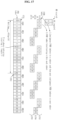
- the Third Generation Partnership Project (3GPP) supports a type 1 radio frame structure applicable to frequency division duplex (FDD), and a type 2 radio frame structure applicable to time division duplex (TDD).
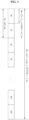
- the structure of a type 1 radio frame is shown in FIG. 1 .
- the type 1 radio frame includes ten subframes, each of which consists of two slots.
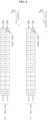
- the structure of a type 2 radio frame is shown in FIG. 2 .
- the type 2 radio frame includes two half frames, each of which is made up of five subframes, a downlink piloting time slot (DwPTS), a gap period (GP), and an uplink piloting time slot (UpPTS), in which one subframe consists of two slots. That is, one subframe is composed of two slots irrespective of the radio frame type.
- DwPTS downlink piloting time slot
- GP gap period
- UpPTS uplink piloting time slot
- a signal transmitted in each slot can be described by a resource grid including N RB DL N SC RB subcarriers and N symb DL OFDM symbols.
- N RB DL represents the number of resource blocks (RBs) in a downlink
- N SC RB represents the number of subcarriers constituting one RB
- N symb DL represents the number of OFDM symbols in one downlink slot.
- the structure of this resource grid is shown in FIG. 3 .
- a VRB can have the same size as that of the PRB.
- a pair of VRBs have a single VRB index in common (may hereinafter be referred to as a ⁇ VRB number') and are allocated over two slots of one subframe.
- N RB DL VRBs belonging to a first one of two slots constituting one subframe are each assigned any one index of 0 to N RB DL ⁇ 1
- N RB DL VRBs belonging to a second one of the two slots are likewise each assigned any one index of 0 to N RB DL ⁇ 1 .
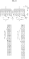
- the localized VRBs are directly mapped to PRBs and the indexes of the LVRBs correspond to the indexes of the PRBs.
- LVRBs of index i correspond to PRBs of index i. That is, an LVRB1 having the index i corresponds to a PRB1 having the index i, and an LVRB2 having the index i corresponds to a PRB2 having the index i (see FIG. 5 ). In this case, it is assumed that the VRBs of FIG. 5 are all allocated as LVRBs.
- the distributed VRBs may not be directly mapped to PRBs. That is, the indexes of the DVRBs can be mapped to the PRBs after being subjected to a series of processes.
- the order of a sequence of consecutive indexes of the DVRBs can be interleaved by a block interleaver.
- the sequence of consecutive indexes means that the index number is sequentially incremented by one beginning with 0.
- a sequence of indexes outputted from the interleaver is sequentially mapped to a sequence of consecutive indexes of PRB1s (see FIG. 6 ). It is assumed that the VRBs of FIG. 6 are all allocated as DVRBs.
- the sequence of indexes outputted from the interleaver is cyclically shifted by a predetermined number and the cyclically shifted index sequence is sequentially mapped to a sequence of consecutive indexes of PRB2s (see FIG. 7 ). It is assumed that the VRBs of FIG. 7 are all allocated as DVRBs. In this manner, PRB indexes and DVRB indexes can be mapped over two slots.
- a sequence of consecutive indexes of the DVRBs may be sequentially mapped to the sequence of consecutive indexes of the PRB1s without passing through the interleaver. Also, the sequence of consecutive indexes of the DVRBs may be cyclically shifted by the predetermined number without passing through the interleaver and the cyclically shifted index sequence may be sequentially mapped to the sequence of consecutive indexes of the PRB2s.
- a PRB1(i) and a PRB2(i) having the same index i can be mapped to a DVRB1(m) and a DVRB2(n) having different indexes m and n.
- a PRB1(1) and a PRB2(1) are mapped to a DVRB1(6) and a DVRB2(9) having different indexes.
- a frequency diversity effect can be obtained based on the DVRB mapping scheme.
- radio resources can be allocated to each terminal with a LVRB and/or DVRB scheme.
- the information indicating which scheme is used can be transmitted with a bitmap format.
- the allocation of radio resources to each terminal can be carried out in units of one RB.
- resources can be allocated with a granularity of '1' RB, but a large amount of bit overhead is required to transmit the allocation information with the bitmap format.
- An object of the present invention devised to solve the problem lies on a resource scheduling method for efficiently combining scheduling of an FSS scheme and scheduling of an FDS scheme.
- an interleaved index d p1 mapped to the index p may be given as in expression (7) or expression (8), and a cyclically shifted index d p2 mapped to the index p may be given as in expression (9) or expression (10).
- R is the number of rows of the block interleaver
- C is the number of columns of the block interleaver
- N DVRB is the number of resource blocks used for the distributively allocated virtual resource blocks
- mod means a modulo operation.
- the number (N DVRB ) of the virtual resource blocks may be a multiple of a value obtained by multiplying the number M RBG of the consecutive physical resource blocks constituting the RBG by the number (N D ) of physical resource blocks to which one virtual resource block is mapped.
- the number N DVRB of the virtual resource blocks may be a common multiple of a value obtained by multiplying a square (M RBG 2 ) of the number of the consecutive physical resource blocks constituting the RBG by the number (N D ) of physical resource blocks to which one virtual resource block is mapped and a degree (D) of the block interleaver.
- the degree (D) of the block interleaver may be a multiple of the number (N D ) of physical resource blocks to which one virtual resource block is mapped.
- the first sub-PRB corresponds to the aforementioned PRB1
- the second sub-PRB corresponds to the aforementioned PRB2.
- the first sub-VRB corresponds to the aforementioned VRB1
- the second sub-VRB corresponds to the aforementioned VRB2.
- the DVRB mapping rules for obtaining a frequency effect is described on the basis of one subframe. Therefore, it will be understood that all embodiments of the detailed description of the invention are concepts including an RB mapping method in the 3GPP.
- a 'virtual resource block (VRB)' represents a virtual unit resource for data transmission.
- the number of REs included in one VRB is equal to that of REs included in one PRB, and, when data is transmitted, one VRB can be mapped to one PRB or some areas of a plurality of PRBs.
- a ⁇ distributed virtual resource block (DVRB)' is another type of the VRB.
- One DVRB is mapped to a plurality of PRBs in a distributed manner.
- DVRB_UE ' represents the maximum number of DVRBs allocable to one UE.
- 'N DivOrder' represents a diversity order required in the system.
- the diversity order is defined by the number of RBs which are not adjacent to each other.
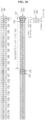
- FIG. 9 shows an example of definitions of LVRBs and DVRBs.
- Downlink data transmission from a base station to a specific terminal or uplink data transmission from the specific terminal to the base station is made through one or more VRBs in one subframe.
- the base station transmits data to the specific terminal, it has to notify the terminal of which one of the VRBs is used for data transmission. Also, in order to enable the specific terminal to transmit data, the base station has to notify the terminal of which one of the VRBs is allowed to use for data transmission.
- the length of available RBs is different depending on respective start points, and the number of combinations of RB allocation is N LVRB (N LVRB +1)/2 in the end. Accordingly, the number of bits required for the combinations is ceiling(log 2 (N LVRB (N LVRB +1)/2)).
- ceiling(x) means rounding "x" up to a nearest integer. This method is advantageous over the bitmap scheme in that the number of bits does not so significantly increase with the increase in the number N LVRB .
- a method for notifying a user equipment (UE) of DVRB allocation it is necessary to previously promise the positions of respective divided parts of DVRBs distributively transmitted for a diversity gain.
- additional information may be required to directly notify the positions.
- the number of bits for signaling for the DVRBs is set to be equal to the number of bits in LVRB transmission of the above-stated compact scheme, it is possible to simplify a signaling bit format in a downlink. As a result, there are advantages that the same channel coding can be used, etc.
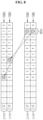
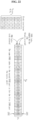
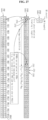
- FIG. 11 illustrates an example of a method for mapping two DVRBs having consecutive indexes to a plurality of contiguous PRBs.
- first divided parts 1101 and 1102 and second divided parts 1103 and 1104 are spaced part from each other by a gap 1105, while divided parts belonging to each of the upper divided parts and lower divided parts are contiguous to each other, so that the diversity order becomes 2.
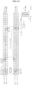
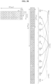
- FIG. 12 illustrates an example of a method for mapping two DVRBs having consecutive indexes to a plurality of spaced PRBs.
- ⁇ spaced PRBs' means that the PRBs are not adjacent to each other.
- consecutive DVRB indexes can be allowed to be distributed, not correspond to contiguous PRBs.
- a DVRB index '0' and a DVRB index '1' are not arranged contiguous to each other.
- DVRB indexes are arranged in the order of 0, 8, 16, 4, 12, 20, ..., and this arrangement can be obtained by inputting the consecutive indexes shown in FIG. 11 to, for example, a block interleaver.
- FIG. 13 illustrates the case where one UE is allocated four DVRBs under the same rules as those of FIG. 12 .
- the diversity order increases to 7.
- the diversity gain converges.
- the results of existing studies represent that the increase in the diversity gain is insignificant when the diversity order is about 4 or more.
- the un-mapped parts of PRBs 1301, 1302, 1303, 1304, and 1305 can be allocated and mapped for other UE which uses DVRBs, however, the un-mapped parts cannot be allocated and mapped for another UE which uses LVRBs. Therefore, when there are no other UEs using DVRBs, there is a disadvantage that the un-mapped parts of the PRBs 1301, 1302, 1303, 1304 and 1305 cannot help being left empty, not used.
- the distributed arrangement of DVRBs breaks consecutiveness of available PRBs, resulting in a restriction in allocating consecutive LVRBs.
- a first embodiment and second embodiment of the present invention are directed to methods for setting a relative distance between divided parts of a DVRB mapped to PRBs to 0.
- respective divided parts of each of the DVRBs can be distributively allocated to different PRBs, thereby raising the diversity order.
- the respective divided parts of each DVRB may be allocated to the same PRB, not distributively allocated to different PRBs. In this case, it is possible to reduce the number of PRBs to which DVRBs are distributively allocated, thus limiting the diversity order.
- This embodiment is directed to a method for switching divided parts to a distributed/non-distributed mode by setting a reference value for the number of DVRBs allocated to one UE.
- the 'distributed mode' refers to a mode where the gap between divided DVRB parts is not 0, and the 'non-distributed mode' refers to a mode where the gap between divided DVRB parts is 0.
- the divided parts are allocated to the same PRB, not distributively allocated.
- This allocation of the divided parts to the same PRB can reduce the number of PRBs to which DVRBs are distributively mapped, thus limiting the diversity order.
- a gap which is a relative distance between divided parts of each DVRB mapped to PRBs, is set to 0.
- This embodiment is directed to a method for switching divided parts to a distributed/non-distributed mode using a control signal.
- the 'distributed mode' refers to a mode where the gap between divided DVRB parts is not 0, and the 'non-distributed mode' refers to a mode where the gap between divided DVRB parts is 0.
- the embodiment 2 is a modified version of the embodiment 1.
- M th is not set, and, as needed, a control signal is transmitted and received to switch divided parts to the distributed/non-distributed mode.
- divided DVRB parts can be distributed to raise the diversity order or be mapped to the same PRB to lower the diversity order.
- divided DVRB parts are distributively mapped as shown in FIG. 12 or 13 .
- divided DVRB parts are mapped to the same PRB as shown in FIG. 14 .
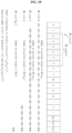
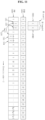
- FIG. 15 illustrates a bitmap configuration
- a signal for resource allocation consists of a header 1501 and a bitmap 1502.
- the header 1501 indicates the structure of the bitmap 1502 being transmitted, namely, a bitmap scheme, by indicating a signaling scheme.
- the bitmap scheme is classified into two types, an RBG scheme and a subset scheme.
- RBs are grouped into a plurality of groups. RBs are mapped in units of one group. That is, a plurality of RBs constituting one group have association of mapping.
- all RBs can be divided into a total of eleven groups. As a result, only a bitmap of 11 bits is required, thereby significantly reducing the amount of control information.
- resources are allocated on this RBG basis, they cannot be allocated in units of one RB, so that they cannot be minutely allocated.
- the subset scheme is used.
- a plurality of RBGs are set as one subset, and resources are allocated on an RB basis within each subset.
- '3' is the number of RBs constituting each RBG stated above.
- the header information 1501 is required to indicate which one of the RBG scheme and subset scheme is used for the bitmap and which subset is used if the subset scheme is used.
- the header information 1501 just indicates which one of the RBG scheme and subset scheme is used and some bits of the bitmap used for the RBGs are used to indicate the subset type, all the RBs in all the subsets may not be utilized.
- a 2-bit subset indicator 1503 is required to identify the subsets.
- a total of 12 RBs are assigned to the subset 1 1504 or 1505, and only 9 bits are left in the bitmap of a total of 11 bits if 2 bits of the subset indicator 1503 are excepted from the bitmap. It is not possible to individually indicate all of the twelve RBs with 9 bits.
- one bit of the RBG bitmap can be assigned as a shift indicator 1506 so that it can be used to shift the position of an RB indicated by the subset bitmap.
- the subset indicator 1503 indicates the subset 1 and the shift indicator 1506 indicates ⁇ shift 0'
- the remaining 8 bits of the bitmap are used to indicate RB0, RB1, RB2, RB9, RB10, RB11, RB18 and RB19 (see 1504).
- the remaining 8 bits of the bitmap are used to indicate RB10, RB11, RB18, RB19, RB20, RB27, RB28 and RB29 (see 1505).
- the subset indicator 1503 has been described in the above example to indicate the subset 1 1504 or 1505, it may indicate the subset 2 or subset 3. Accordingly, it can be seen that eight RBs can be mapped in units of one RB with respect to each combination of the subset indicator 1503 and shift indicator 1506. Also, referring to FIG. 15 , in the present embodiment, the numbers of RBs assigned to the subset 1, subset 2 and subset 3 are 12, 11 and 9 which are different, respectively. Accordingly, it can be seen that four RBs cannot be used in the case of the subset 1, three RBs cannot be used in the case of the subset 2 and one RB cannot be used in the case of the subset 3 (see shaded areas). FIG. 15 is nothing but an illustration, and the present embodiment is thus not limited thereto.
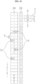
- FIG. 16 illustrates an example of a method for mapping based on a combination of the bitmap scheme and compact scheme.
- DVRB0 to DVRB11 are distributively mapped within a subset 1 (1703)
- DVRB12 to DVRB22 are then distributively mapped within a subset 2 (1704)
- DVRB23 to DVRB31 are then distributively mapped within a subset 3 (1705).
- This mapping can be carried out by a method of using a block interleaver for each subset or any other method.
- gap information can be used to map divided parts of the same DVRB within the same subset.
- a parameter for all PRBs such as the aforementioned 'Gap', may be used.
- another parameter for one subset, 'Gap subset ' may be used. This will hereinafter be described in detail.
- the embodiment 5 is directed to a method for setting a relative distance between divided DVRB parts to a multiple of the square of the size of an RBG.
- a method for mapping consecutive DVRB indexes to non-contiguous, distributed PRBs uses a block interleaver and configures the interleaver such that it has a degree equal to a target diversity order N DivOrder .
- the degree of the interleaver can be defined as follows.
- the interleaver when data is written, the data is written while the index thereof is sequentially incremented. At this time, the writing is performed in such a manner that, after one column is completely filled, a column index is incremented by one and a next column is filled. In each column, the writing is performed while a row index is incremented. For reading from the interleaver, the reading is performed in such a manner that, after one row is completely read, a row index is incremented by one and a next row is read.
- the interleaver can be referred to as an m-degree interleaver.
- a block interleaver having m rows and n columns
- data writing may be performed in such a manner that, after one row is filled, the process proceeds to a next row
- data reading may be performed in such a manner that, after one column is read, the process proceeds to a next column.
- the interleaver can be referred to as an n-degree interleaver.
- a DVRB index order of a data sequence outputted from the interleaver can be used as an index order of first divided parts of DVRBs, and a DVRB index order of a data sequence obtained by cyclically shifting the outputted data sequence by N DVRB /N D can be used as an index order of the remaining divided parts.
- N D divided parts generated from DVRBs are mapped to only N D PRBs in pairs, and the difference between paired DVRB indexes is K.
- a DVRB index order 1901 of a data sequence outputted from the interleaver is given as "0 ⁇ 6 ⁇ 12 ⁇ 18 ⁇ 1 ⁇ 7 ⁇ 13 ⁇ 19 ⁇ 2 ⁇ 8 ⁇ 14 ⁇ 20 & 3 & 9 & 15 & 21 ⁇ 4 ⁇ 10 & 16 & 22 ⁇ 5 & 11 & 17 & 23”
- N null the number of nulls filled in the interleaver.
- N DVRB is a multiple of N DivOrder .
- N DVRB is not a multiple of N DivOrder , it is necessary to take a null filling method into consideration because it is impossible to completely fill data in the interleaver.
- nulls are filled in elements of a last column, except for elements corresponding to N Remain values, as shown in FIG. 20a or 20b .
- nulls are rearwardly filled in the above example, they may be positioned before a first index value.
- the N Remain values are filled in elements, starting from a first element.
- nulls may be arranged at predetermined positions, respectively.
- FIGs. 21a and 21b illustrates a null arranging method according to one embodiment of the present invention. Referring to FIG. 21a and 21b , it can be seen that nulls are uniformly distributed, as compared to the case of FIGs. 20a and 20b .
- N DivOrder corresponding to the degree of the interleaver is divided into N D groups each having a size of K, and nulls are uniformly distributed in all the groups.
- K 3.
- One null is written in the first group G2101.
- one null is written in the second group G2102.
- nulls are distributively written.
- N Remain values remain finally.
- indexes corresponding to the remaining values are arranged in N D groups such that they are uniformly distributed, it is possible to uniformly arrange nulls.
- a reference value M th for M may be set. Based on the reference value M th , the divided parts of each DVRB may be distributively assigned to different PRBs, respectively, to raise the diversity order. Alternatively, the divided parts of each DVRB may be assigned to the same PRB without being distributed to different PRBs. In this case, it is possible to reduce the number of PRBs, to which DVRBs are distributively mapped, and thus to limit the diversity order.
- DVRB indexes of a data sequence outputted from the interleaver are applied, in common, to all divided parts of each DVRB such that they are mapped to PRBs, as shown in FIG. 22 .
- DVRB indexes of a data sequence outputted from the interleaver have an order of "0 ⁇ 6 ⁇ 12 ⁇ 18 ⁇ 1 ⁇ 7 ⁇ 13 ⁇ 19 ⁇ 2 ⁇ 8 ⁇ 14 ⁇ 20 ⁇ 3 ⁇ 9 ⁇ 15 ⁇ 21 ⁇ 4 ⁇ 10 ⁇ 16 ⁇ 22 ⁇ 5 ⁇ 11 ⁇ 17 ⁇ 23".
- each data sequence DVRB index is applied, in common, to first and second divided parts 2201 and 2202 of each DVRB.
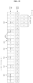
- FIG. 23 illustrates the case in which a UE1, which is subjected to a scheduling in a scheme of mapping respective divided parts of each DVRB to different PRBs, as shown in FIG. 19 , and a UE2, which is subjected to a scheduling in a scheme of mapping the divided parts of each DVRB to the same PRB, as shown in FIG. 22 , are simultaneously multiplexed. That is, FIG. 23 illustrates the case in which the UE1 and UE2 are simultaneously scheduled in accordance with the methods of the embodiments 6 and 8, respectively.
- the UE1 is allocated a DVRB0, DVRB1, DVRB2, DVRB3, and DVRB4 (2301), whereas the UE2 is allocated a DVRB6, DVRB7, DVRB8, DVRB9, DVRB10, and DVRB11 (2302).
- the UE1 is scheduled in such a manner that the divided parts of each DVRB are mapped to different PRBs, respectively, whereas the UE2 is scheduled in such a manner that the divided parts of each DVRB are mapped to the same PRB.
- the PRBs used for the UE1 and UE2 include a PRB0, PRB1, PRB4, PRB5, PRB8, PRB9, PRB12, PRB13, PRB16, PRB17, PRB20, and PRB21, as shown by "2303" in FIG. 23 .
- the PRB8 and PRB20 are partially used.
- each DVRB is mapped to distributed PRBs, respectively.
- the difference between the paired DVRB indexes is limited to a value of K or less. Accordingly, this scheme has no influence on DVRBs spaced apart from each other by a gap of more than K. Accordingly, it is possible to easily distinguish indexes usable in the "case in which the divided parts of each DVRB are mapped to the same PRB" from unusable indexes.
- the difference between the DVRB indexes paired for PRBs may not be fixed to a specific value.
- the method of FIG. 21 may be used as described above.
- the number of RBs used for DVRBs namely, N DVRB
- N DivOrder the number of RBs used for DVRBs
- no null is filled in the rectangular matrix of the interleaver when the number of RBs used for DVRBs, namely, N DVRB , is limited to a multiple of D.
- Constants used in Expressions 1 to 11 expressing the relation between DVRB and PRB indexes are defined as follows.
- FIG. 25a is a view for explaining the above-described constants.
- round( ⁇ ) represents an integer nearest to a numeral indicated in “()”.
- min(x,y) represents the value which is not larger among x and y, whereas "max(x,y)” represents the value which is not smaller among x and y.
- N DVRB is a multiple of C
- a DVRB index d is given
- a PRB index can be derived using Expression 3.
- p 1 , d mod d C ⁇ R + ⁇ d / C ⁇ p 2
- d mod p 1 , d + N DVRB / 2 , N DVRB
- the method of FIG. 25b is similar to the method of FIGs. 20a and 20b .
- a PRB index p is given, a DVRB index can be derived using Expression 4.
- a PRB index can be derived using Expression 5.
- p 1 , d ′ mod d C ⁇ R + ⁇ d / C ⁇ p 2
- d mod( p 1, d + N DVRB / 2, N DVRB )
- FIG. 25c illustrates a method corresponding to the method of the embodiment 7 and FIGs. 21a and 21b .
- the method of FIG. 25c may be explained using Expressions 6 to 8.
- a PRB index p is given, a DVRB index can be derived using Expression 6 or 7.
- a PRB index can be derived using Expression 8.
- p 1 , d ′ mod d C ⁇ R + ⁇ d / C ⁇ p 2
- d mod( p 1, d + N DVRB / 2, N DVRB )
- N null represents the number of nulls to be included in the interleaver. This value N null may be a predetermined value.
- a DVRB index p is given, a DVRB index can be derived using Expression 9 or 10.
- d p 1 mod p ′ , R ⁇ C + ⁇ p ′ / R ⁇
- p ′ ⁇ p
- when N null 0 or p ⁇ R ⁇ N null / 2 or R ⁇ p ⁇ 2 R ⁇ N null / 2 p + N null / 2
- p 1 mod p ′ , 2 R ⁇ C / 2 + ⁇ p ′ / 2 R ⁇
- p ′ ⁇ p + R ⁇ N null / 2
- a PRB index can be derived using Expression 11.
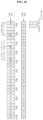
- the RBG8 can be applied to a scheme using a resource allocation on an RBG basis, different from the method of FIG. 26 .
- DVRB indexes paired in one PRB cannot be paired in another PRB.
- the DVRB indexes 1 and 26 paired in the PRB1 (2601) are also paired in the PRB26 (2603).
- the DVRB indexes 1 and 27 paired in the PRB1 (2701) cannot be paired in the PRB25 or PRB27 (2703 or 2705).
- the number of RBs used for DVRBs namely, N DVRB
- N D ⁇ M RBG the number of RBs used for DVRBs
- the first and second divided parts of each DVRB belong to different subsets, respectively.
- the gap should be set to be a multiple of the square of M RBG (M RBG 2 ).
- the number of RBs used for DVRBs namely, N DVRB
- N D ⁇ M RBG 2 the number of RBs used for DVRBs, namely, N DVRB
- the number of RBs used for DVRBs is limited to a multiple of N D ⁇ M RBG 2 , in order to make the two divided parts of each DVRB belong to the same subset, and to make DVRBs be paired.
- N DVRB indexes When DVRB indexes are interleaved as shown in FIG. 29 , it may be possible to set N DVRB to a multiple of N D ⁇ M RBG when the DVRB indexes are mapped to PRBs. In this case, however, there may be an occasion that the rectangular interleaver matrix is incompletely filled with DVRB indexes, as shown in FIGs. 20a and 20b . In this case, accordingly, it is necessary to fill nulls in non-filled portions of the rectangular interleaver matrix. In order to avoid the occasion requiring filling of nulls in a block interleaver of degree D, it is necessary to limit the number of RBs used for DVRBs to a multiple of D.
- writing is performed in such a manner that, after one column is completely filled, a next column is filled, and reading is performed in such a manner that, after one row is completely read, a next row is read.
- Expression 15 This may be expressed by Expression 15 as a generalized mathematic expression.
Landscapes
- Engineering & Computer Science (AREA)
- Signal Processing (AREA)
- Computer Networks & Wireless Communication (AREA)
- Quality & Reliability (AREA)
- Mobile Radio Communication Systems (AREA)
- Error Detection And Correction (AREA)
Applications Claiming Priority (10)
| Application Number | Priority Date | Filing Date | Title |
|---|---|---|---|
| US1958908P | 2008-01-07 | 2008-01-07 | |
| US2488608P | 2008-01-30 | 2008-01-30 | |
| US2611308P | 2008-02-04 | 2008-02-04 | |
| US2818608P | 2008-02-12 | 2008-02-12 | |
| US2851108P | 2008-02-13 | 2008-02-13 | |
| US3335808P | 2008-03-03 | 2008-03-03 | |
| US3730208P | 2008-03-17 | 2008-03-17 | |
| US3877808P | 2008-03-24 | 2008-03-24 | |
| KR1020080131114A KR100925441B1 (ko) | 2008-01-07 | 2008-12-22 | 분산형 가상자원블록 스케쥴링 방법 |
| EP09150177.5A EP2077650B1 (en) | 2008-01-07 | 2009-01-07 | Method for scheduling distributed virtual resource blocks |
Related Parent Applications (2)
| Application Number | Title | Priority Date | Filing Date |
|---|---|---|---|
| EP09150177.5A Division EP2077650B1 (en) | 2008-01-07 | 2009-01-07 | Method for scheduling distributed virtual resource blocks |
| EP09150177.5A Division-Into EP2077650B1 (en) | 2008-01-07 | 2009-01-07 | Method for scheduling distributed virtual resource blocks |
Publications (3)
| Publication Number | Publication Date |
|---|---|
| EP3379762A2 EP3379762A2 (en) | 2018-09-26 |
| EP3379762A3 EP3379762A3 (en) | 2019-01-16 |
| EP3379762B1 true EP3379762B1 (en) | 2024-07-10 |
Family
ID=40577749
Family Applications (2)
| Application Number | Title | Priority Date | Filing Date |
|---|---|---|---|
| EP18171915.4A Active EP3379762B1 (en) | 2008-01-07 | 2009-01-07 | Method for scheduling distributed virtual resource blocks |
| EP09150177.5A Active EP2077650B1 (en) | 2008-01-07 | 2009-01-07 | Method for scheduling distributed virtual resource blocks |
Family Applications After (1)
| Application Number | Title | Priority Date | Filing Date |
|---|---|---|---|
| EP09150177.5A Active EP2077650B1 (en) | 2008-01-07 | 2009-01-07 | Method for scheduling distributed virtual resource blocks |
Country Status (9)
| Country | Link |
|---|---|
| US (6) | US7808949B2 (enExample) |
| EP (2) | EP3379762B1 (enExample) |
| JP (1) | JP5048844B2 (enExample) |
| KR (1) | KR100925441B1 (enExample) |
| CN (2) | CN103326846B (enExample) |
| CA (1) | CA2711319C (enExample) |
| ES (1) | ES2984247T3 (enExample) |
| TW (1) | TWI401934B (enExample) |
| WO (1) | WO2009088202A2 (enExample) |
Families Citing this family (45)
| Publication number | Priority date | Publication date | Assignee | Title |
|---|---|---|---|---|
| JP4916389B2 (ja) * | 2007-06-19 | 2012-04-11 | 株式会社エヌ・ティ・ティ・ドコモ | 無線通信制御方法、基地局装置、およびユーザ装置 |
| RU2480916C2 (ru) * | 2007-06-19 | 2013-04-27 | Панасоник Корпорэйшн | Способ размещения каналов и устройство базовой станции радиосвязи |
| CN101904207B (zh) * | 2008-01-04 | 2014-02-19 | 松下电器产业株式会社 | 信道配置方法和无线通信基站装置 |
| KR100913099B1 (ko) | 2008-01-07 | 2009-08-21 | 엘지전자 주식회사 | 분산형 가상자원블록 스케쥴링 방법 |
| KR100925441B1 (ko) * | 2008-01-07 | 2009-11-06 | 엘지전자 주식회사 | 분산형 가상자원블록 스케쥴링 방법 |
| US8493835B2 (en) | 2008-03-26 | 2013-07-23 | Qualcomm, Incorporated | Method and apparatus for mapping virtual resources to physical resources in a wireless communication system |
| US8125974B2 (en) * | 2008-05-02 | 2012-02-28 | Wi-Lan, Inc. | Transmit emission control in a wireless transceiver |
| GB2464987A (en) * | 2008-11-03 | 2010-05-05 | Nec Corp | Methods for designating resource allocation |
| US9071310B2 (en) * | 2009-01-12 | 2015-06-30 | Qualcomm Incorporated | Method and apparatus for enabling multiple transmission modes in a wireless communication system |
| US9520933B2 (en) | 2009-01-12 | 2016-12-13 | Qualcomm Incorporated | Method and apparatus for enabling multiple transmission modes based on multiple search spaces |
| US9673952B2 (en) | 2009-04-10 | 2017-06-06 | Qualcomm Inc. | Method and apparatus for supporting user equipments on different system bandwidths |
| KR101650749B1 (ko) * | 2009-08-18 | 2016-08-24 | 삼성전자주식회사 | 릴레이를 위한 백홀 서브프레임의 제어 채널 자원 할당 방법 및 장치 |
| US20110069637A1 (en) * | 2009-09-18 | 2011-03-24 | Futurewei Technologies, Inc. | System and Method for Control Channel Search Space Location Indication for a Relay Backhaul Link |
| US9276710B2 (en) | 2009-12-21 | 2016-03-01 | Qualcomm Incorporated | Method and apparatus for resource allocation with carrier extension |
| GB2476488A (en) * | 2009-12-23 | 2011-06-29 | Nec Corp | Allocating physical resource blocks to a user device for transmitting uplink data |
| US8958382B2 (en) * | 2010-05-11 | 2015-02-17 | Lg Electronics Inc. | Method and device for receiving downlink signals |
| WO2011152663A2 (ko) * | 2010-06-01 | 2011-12-08 | 엘지전자 주식회사 | 무선 통신 시스템에서 자원 할당 방법 및 장치 |
| US9571239B2 (en) * | 2010-12-16 | 2017-02-14 | Lg Electronics Inc. | Method and apparatus for transmitting channel information in cognitive radio network and method and apparatus for performing channel switching |
| WO2012134042A2 (ko) * | 2011-03-30 | 2012-10-04 | 엘지전자 주식회사 | 무선 통신 시스템에서 트래픽 지시 맵을 생성하는 방법 및 장치 |
| CA2859692A1 (en) | 2011-12-23 | 2013-06-27 | Fujitsu Limited | Method and apparatus for resource mapping of a physical downlink control channel |
| CN103327615B (zh) * | 2012-03-20 | 2016-04-20 | 华为技术有限公司 | 资源分配指示方法、资源分配方法及设备 |
| CN105917610B (zh) * | 2013-12-10 | 2020-05-12 | 瑞典爱立信有限公司 | 用于数据无线电传输的基于组的资源单元映射 |
| WO2017135799A1 (en) * | 2016-02-05 | 2017-08-10 | Samsung Electronics Co., Ltd. | Multiple access method, and corresponding transmission method, receiver and transmitter |
| RU2638544C2 (ru) * | 2016-06-03 | 2017-12-14 | Фудзицу Лимитед | Способ и устройство для отображения ресурсов физического канала управления нисходящей линии связи |
| CN107635286B (zh) * | 2016-07-18 | 2024-04-02 | 北京三星通信技术研究有限公司 | 一种数据或控制信息的加扰和解扰的方法与设备 |
| KR102897791B1 (ko) * | 2016-10-17 | 2025-12-10 | 에스케이하이닉스 주식회사 | 메모리 시스템 및 메모리 시스템의 동작 방법 |
| JP2020017776A (ja) * | 2016-11-02 | 2020-01-30 | 株式会社Nttドコモ | 基地局及びユーザ装置 |
| CN108235433B (zh) * | 2016-12-15 | 2021-07-09 | 华为技术有限公司 | 通信方法、基站和终端设备 |
| WO2018187902A1 (en) | 2017-04-10 | 2018-10-18 | Qualcomm Incorporated | An efficient interleaver design for polar codes |
| EP3852289B1 (en) * | 2017-04-14 | 2024-10-09 | LG Electronics Inc. | Method and apparatus for performing initial connection in wireless communication system |
| KR101950995B1 (ko) * | 2017-06-08 | 2019-02-22 | 엘지전자 주식회사 | 무선 통신 시스템에서 자원 할당 관련 시그널링 방법 및 상기 방법을 이용하는 장치 |
| CN109392174B (zh) * | 2017-08-11 | 2021-02-12 | 华为技术有限公司 | 一种资源配置方法及设备 |
| CN111066357B (zh) * | 2017-09-11 | 2023-05-05 | 中兴通讯股份有限公司 | 信息传输系统 |
| WO2019080015A1 (zh) | 2017-10-25 | 2019-05-02 | 华为技术有限公司 | 一种数据读写方法、装置和存储服务器 |
| US12114291B2 (en) * | 2017-11-10 | 2024-10-08 | Qualcomm Incorporated | Virtual resource block to physical resource block mapping in new radio |
| CN111247849B (zh) * | 2017-11-17 | 2023-05-12 | 松下电器(美国)知识产权公司 | 基站、用户设备和无线通信方法 |
| CN109803411B (zh) * | 2017-11-17 | 2021-09-14 | 维沃移动通信有限公司 | 资源映射方法、确定方法、网络侧设备及用户终端 |
| CN109995467B (zh) * | 2018-01-03 | 2020-09-01 | 电信科学技术研究院 | 一种资源映射方法及装置、设备 |
| CN110011757B (zh) * | 2018-01-05 | 2022-01-04 | 维沃移动通信有限公司 | 基本交织单元的处理方法及通信设备 |
| CN110035533B (zh) | 2018-01-12 | 2023-06-06 | 华为技术有限公司 | 一种资源映射方法及设备 |
| CN110035548B (zh) * | 2018-01-12 | 2022-12-30 | 华为技术有限公司 | 通信的方法和通信设备 |
| WO2020032700A1 (ko) * | 2018-08-09 | 2020-02-13 | 엘지전자 주식회사 | 무선 통신 시스템에서 신호를 송수신하는 방법 및 이를 지원하는 장치 |
| US11916671B2 (en) | 2019-09-18 | 2024-02-27 | Qualcomm Incorporated | Methods for interleaved mapping |
| EP4147402B1 (en) * | 2020-05-05 | 2025-07-02 | Qualcomm Incorporated | Vrb-to-prb allocation for disjoint bwp segments |
| CN115052347B (zh) * | 2021-03-09 | 2025-08-26 | 中国移动通信有限公司研究院 | 一种资源映射的方法、装置及设备 |
Family Cites Families (69)
| Publication number | Priority date | Publication date | Assignee | Title |
|---|---|---|---|---|
| US5710768A (en) | 1994-09-30 | 1998-01-20 | Qualcomm Incorporated | Method of searching for a bursty signal |
| ES2176280T3 (es) * | 1995-08-21 | 2002-12-01 | Cit Alcatel | Metodo para intercalar cuadros de datos, dispositivo de correccion cronologica de error y modulador que incluye tal dispositivo. |
| US6377809B1 (en) | 1997-09-16 | 2002-04-23 | Qualcomm Incorporated | Channel structure for communication systems |
| US6574211B2 (en) | 1997-11-03 | 2003-06-03 | Qualcomm Incorporated | Method and apparatus for high rate packet data transmission |
| US6631491B1 (en) | 1997-11-10 | 2003-10-07 | Ntt Mobile Communications Network, Inc. | Interleaving method, interleaving apparatus, and recording medium in which interleave pattern generating program is recorded |
| KR100547838B1 (ko) | 1998-11-17 | 2006-03-23 | 삼성전자주식회사 | 부호분할다중접속 통신시스템에서 전용제어채널의 핸드오프방법 |
| FR2806576B1 (fr) | 2000-03-15 | 2004-04-23 | Nortel Matra Cellular | Procede d'emission de signaux radio, reseau d'acces et terminal de radiocommunication appliquant le procede |
| US7245594B1 (en) | 2000-05-12 | 2007-07-17 | Qualcomm Incorporated | Method and apparatus for fast closed-loop rate adaptation in a high rate packet data transmission |
| US7233810B2 (en) * | 2000-08-03 | 2007-06-19 | Infineon Technologies Ag | Dynamically reconfigurable universal transmitter system |
| US20020122410A1 (en) * | 2001-02-13 | 2002-09-05 | Cybiko Inc. | Method of wireless data exchange amongst devices of limited range |
| US7386000B2 (en) | 2001-04-17 | 2008-06-10 | Nokia Corporation | Packet mode speech communication |
| US7313190B2 (en) * | 2003-03-11 | 2007-12-25 | Texas Instruments Incorporated | Efficient bit interleaver for a multi-band OFDM ultra-wideband system |
| JP2005088801A (ja) * | 2003-09-18 | 2005-04-07 | Denso Corp | 情報処理システム |
| KR100575434B1 (ko) * | 2003-11-19 | 2006-05-03 | 한국전자통신연구원 | 직교주파수 분할 다중 접속 기반 셀룰러 시스템에서의 자원 공간 분할 및 물리 채널 할당 방법 |
| US7570695B2 (en) * | 2003-12-18 | 2009-08-04 | Intel Corporation | Method and adaptive bit interleaver for wideband systems using adaptive bit loading |
| US7159096B2 (en) | 2004-03-31 | 2007-01-02 | Marvell International Ltd. | Method and apparatus to perform memory management |
| US7818475B2 (en) * | 2004-04-30 | 2010-10-19 | Emc Corporation | Storage switch mirrored write sequence count management |
| WO2006075042A1 (en) * | 2005-01-11 | 2006-07-20 | Nokia Corporation | Method for indicating and detecting transmission resource allocations in a multi-user communication system |
| KR20060106223A (ko) * | 2005-04-06 | 2006-10-12 | 삼성전자주식회사 | 직교 주파수 분할 다중 시스템에서 비트 삽입 및 코드 변조방식의 송신 장치 및 방법 |
| US7685495B2 (en) | 2005-05-12 | 2010-03-23 | Qualcomm Incorporated | Apparatus and method for channel interleaving in communications system |
| WO2007023379A2 (en) | 2005-08-25 | 2007-03-01 | Nokia Corporation | Method and apparatus for control signalling in communication system using different coding scheme |
| WO2007064249A1 (en) * | 2005-11-29 | 2007-06-07 | Telefonaktiebolaget Lm Ericsson (Publ) | Scheduling in a wireless multi-hop relay network |
| US8044571B2 (en) | 2005-12-14 | 2011-10-25 | General Electric Company | Electrode stacks for electroactive devices and methods of fabricating the same |
| KR100834677B1 (ko) * | 2006-01-16 | 2008-06-02 | 삼성전자주식회사 | 주파수 분할 다중접속 방식의 무선 통신 시스템에서 자원할당 장치 및 방법 |
| EP1974579B1 (en) | 2006-01-18 | 2015-04-15 | Telefonaktiebolaget LM Ericsson (publ) | Localized and distributed transmission |
| CN101009515A (zh) * | 2006-01-24 | 2007-08-01 | 华为技术有限公司 | 通信终端设备管理方法及通信终端 |
| WO2007088457A1 (en) | 2006-01-31 | 2007-08-09 | Nokia Corporation | Apparatus , method and computer program product for efficent signaling of user allocations |
| JP4343926B2 (ja) * | 2006-02-08 | 2009-10-14 | 株式会社エヌ・ティ・ティ・ドコモ | 送信装置および送信方法 |
| US7668188B2 (en) * | 2006-02-14 | 2010-02-23 | Broadcom Corporation | Method and system for HSDPA bit level processor engine |
| KR100894142B1 (ko) * | 2006-02-15 | 2009-04-22 | 삼성전자주식회사 | 직교 주파수 분할 다중 접속 방식 시스템에서 무선리소스를 할당하는 방법 및 장치 |
| US20070224995A1 (en) | 2006-03-16 | 2007-09-27 | Nokia Corporation | Apparatus, methods and computer program products providing signaling of time staggered measurement reports and scheduling in response thereto |
| US8014455B2 (en) * | 2006-03-27 | 2011-09-06 | Qualcomm Incorporated | Feedback of differentially encoded channel state information for multiple-input multiple-output (MIMO) and subband scheduling in a wireless communication system |
| US7884921B2 (en) | 2006-04-12 | 2011-02-08 | Nikon Corporation | Illumination optical apparatus, projection exposure apparatus, projection optical system, and device manufacturing method |
| WO2007119148A2 (en) * | 2006-04-13 | 2007-10-25 | Nokia Corporation | Method providing efficient and flexible control signal for resource allocation |
| CN101422067B (zh) | 2006-04-28 | 2016-08-03 | 松下电器(美国)知识产权公司 | 用于多载波通信的无线通信基站装置和无线通信方法 |
| KR100885476B1 (ko) * | 2006-05-02 | 2009-02-24 | 한국전자통신연구원 | 직교 주파수 분할 다중 접속 시스템에서의 하향링크스케줄링 정보 송/수신 방법 |
| WO2008001728A1 (en) | 2006-06-26 | 2008-01-03 | Panasonic Corporation | Radio communication base station device and resource block allocation method |
| KR100961747B1 (ko) | 2006-06-27 | 2010-06-07 | 삼성전자주식회사 | 무선 통신 시스템의 자원 할당 장치 및 방법 |
| US8369424B2 (en) * | 2006-07-14 | 2013-02-05 | Qualcomm Incorporated | Frequency selective and frequency diversity transmissions in a wireless communication system |
| US20080031191A1 (en) * | 2006-08-01 | 2008-02-07 | Nokia Corporation | Shared control channel structure for multi-user MIMO resource allocation |
| CN101123785B (zh) * | 2006-08-11 | 2013-01-23 | 华为技术有限公司 | 一种通信系统中管理终端的方法和系统 |
| EP2070372A2 (en) | 2006-08-21 | 2009-06-17 | Interdigital Technology Corporation | Resource allocation, scheduling, and signaling for grouping real time services |
| CN101146317A (zh) | 2006-09-15 | 2008-03-19 | 北京三星通信技术研究有限公司 | 资源分配及控制信令传输方法 |
| EP1944896A1 (en) | 2007-01-09 | 2008-07-16 | Matsushita Electric Industrial Co., Ltd. | Configuration of control channels in a mobile communication system |
| US8625652B2 (en) * | 2007-01-11 | 2014-01-07 | Qualcomm Incorporated | Collision-free group hopping in a wireless communication system |
| EP1965536A1 (en) * | 2007-02-06 | 2008-09-03 | Mitsubishi Electric Information Technology Centre Europe B.V. | Method of data transmission in a multi-carrier based transmission system and device implementing the method |
| WO2008096833A1 (en) | 2007-02-06 | 2008-08-14 | Nec Corporation | A method of transmitting control channel information in an ofdm communication system downlink |
| US8073062B2 (en) | 2007-02-08 | 2011-12-06 | Motorola Mobility, Inc. | Method and apparatus for downlink resource allocation in an orthogonal frequency division multiplexing communication system |
| KR20080085654A (ko) * | 2007-03-19 | 2008-09-24 | 엘지전자 주식회사 | 셀룰라 다중 반송파 시스템에서 스케줄링 방법 및 스케줄링정보 송신 방법 |
| MX2009010019A (es) | 2007-03-19 | 2009-10-12 | Lg Electronics Inc | Un metodo para la asignacion de recursos y un metodo para la transmision/recepcion de informacion de asignacion de recursos en un sistema de comunicacion movil. |
| BRPI0810979A2 (pt) | 2007-04-27 | 2015-07-21 | Lg Electronics Inc | Método para transmissão de canal de controle em sistema de comunicação móvel |
| RU2480916C2 (ru) * | 2007-06-19 | 2013-04-27 | Панасоник Корпорэйшн | Способ размещения каналов и устройство базовой станции радиосвязи |
| US8526371B2 (en) * | 2007-08-13 | 2013-09-03 | Qualcomm Incorporated | Frequency diverse transmissions in a wireless communication system |
| JP2009060420A (ja) | 2007-08-31 | 2009-03-19 | Sharp Corp | 無線通信システム、無線送信装置、無線受信装置、プログラムおよび無線通信方法 |
| WO2009072842A2 (en) * | 2007-12-05 | 2009-06-11 | Lg Electronics Inc. | Method of allocating resources in wireless communication system |
| JP2009164816A (ja) | 2007-12-28 | 2009-07-23 | Sharp Corp | 無線通信システム、第1の無線通信装置、第2の無線通信装置、無線受信方法および無線送信方法 |
| CN101904207B (zh) | 2008-01-04 | 2014-02-19 | 松下电器产业株式会社 | 信道配置方法和无线通信基站装置 |
| KR100925441B1 (ko) * | 2008-01-07 | 2009-11-06 | 엘지전자 주식회사 | 분산형 가상자원블록 스케쥴링 방법 |
| KR100904433B1 (ko) * | 2008-01-07 | 2009-06-24 | 엘지전자 주식회사 | 분산형 가상자원블록 스케쥴링 방법 |
| KR100913099B1 (ko) * | 2008-01-07 | 2009-08-21 | 엘지전자 주식회사 | 분산형 가상자원블록 스케쥴링 방법 |
| CN101939925B (zh) * | 2008-01-09 | 2014-07-09 | 苹果公司 | 分布式资源块索引到物理资源块的映射 |
| GB2457242A (en) | 2008-02-05 | 2009-08-12 | Nec Corp | Resource allocation in a communication system |
| JP2009188675A (ja) | 2008-02-05 | 2009-08-20 | Sharp Corp | 無線通信システム、基地局装置、移動局装置および無線通信方法 |
| CN101247382A (zh) | 2008-03-25 | 2008-08-20 | 中兴通讯股份有限公司 | 基于ofdm系统的分布式传输资源映射方法和装置 |
| EP2106057A1 (en) | 2008-03-25 | 2009-09-30 | Panasonic Corporation | Resource allocation size dependent transport block size signalling |
| JP2009239340A (ja) | 2008-03-25 | 2009-10-15 | Sharp Corp | 無線通信システム、無線通信装置、無線送信方法および無線受信方法 |
| US8493835B2 (en) | 2008-03-26 | 2013-07-23 | Qualcomm, Incorporated | Method and apparatus for mapping virtual resources to physical resources in a wireless communication system |
| US20090268624A1 (en) * | 2008-04-28 | 2009-10-29 | Sharp Laboratories Of America, Inc. | Systems and methods for measurement and feedback of channel quality indicator information |
| ATE484119T1 (de) | 2008-08-01 | 2010-10-15 | Panasonic Corp | Ressourcenblockzuordnung für wiederholte symbole |
-
2008
- 2008-12-22 KR KR1020080131114A patent/KR100925441B1/ko active Active
-
2009
- 2009-01-06 CN CN201310254521.5A patent/CN103326846B/zh active Active
- 2009-01-06 JP JP2010536863A patent/JP5048844B2/ja active Active
- 2009-01-06 WO PCT/KR2009/000043 patent/WO2009088202A2/en not_active Ceased
- 2009-01-06 CA CA2711319A patent/CA2711319C/en active Active
- 2009-01-06 CN CN2009801018071A patent/CN101911745B/zh active Active
- 2009-01-06 US US12/349,470 patent/US7808949B2/en active Active
- 2009-01-07 EP EP18171915.4A patent/EP3379762B1/en active Active
- 2009-01-07 EP EP09150177.5A patent/EP2077650B1/en active Active
- 2009-01-07 ES ES18171915T patent/ES2984247T3/es active Active
- 2009-01-07 TW TW098100395A patent/TWI401934B/zh active
-
2010
- 2010-08-04 US US12/850,583 patent/US8611290B2/en active Active
- 2010-08-04 US US12/850,575 patent/US8599775B2/en active Active
-
2013
- 2013-08-30 US US14/015,912 patent/US9185701B2/en active Active
-
2015
- 2015-09-24 US US14/864,283 patent/US9603144B2/en active Active
-
2017
- 2017-02-01 US US15/422,388 patent/US10244528B2/en active Active
Non-Patent Citations (1)
| Title |
|---|
| NEC GROUP: "Remaining issues for DVRB to PRB mapping", 3GPP DRAFT; R1-081021-DVRB TO PRB MAPPING, 3RD GENERATION PARTNERSHIP PROJECT (3GPP), MOBILE COMPETENCE CENTRE ; 650, ROUTE DES LUCIOLES ; F-06921 SOPHIA-ANTIPOLIS CEDEX ; FRANCE, vol. RAN WG1, no. Sorrento, Italy; 20080206, 6 February 2008 (2008-02-06), XP050109484 * |
Also Published As
| Publication number | Publication date |
|---|---|
| US20110044270A1 (en) | 2011-02-24 |
| US9185701B2 (en) | 2015-11-10 |
| US20090310476A1 (en) | 2009-12-17 |
| WO2009088202A3 (en) | 2009-10-22 |
| US7808949B2 (en) | 2010-10-05 |
| US8599775B2 (en) | 2013-12-03 |
| CN103326846A (zh) | 2013-09-25 |
| US20110058526A1 (en) | 2011-03-10 |
| US20130343363A1 (en) | 2013-12-26 |
| JP2011507331A (ja) | 2011-03-03 |
| KR100925441B1 (ko) | 2009-11-06 |
| US9603144B2 (en) | 2017-03-21 |
| US20160037516A1 (en) | 2016-02-04 |
| EP2077650A3 (en) | 2012-09-12 |
| CN101911745B (zh) | 2013-07-24 |
| EP3379762A2 (en) | 2018-09-26 |
| CA2711319C (en) | 2013-08-13 |
| CN101911745A (zh) | 2010-12-08 |
| US8611290B2 (en) | 2013-12-17 |
| CA2711319A1 (en) | 2009-07-16 |
| EP3379762A3 (en) | 2019-01-16 |
| EP2077650B1 (en) | 2018-06-27 |
| JP5048844B2 (ja) | 2012-10-17 |
| TW201004251A (en) | 2010-01-16 |
| US10244528B2 (en) | 2019-03-26 |
| KR20090076780A (ko) | 2009-07-13 |
| CN103326846B (zh) | 2015-07-22 |
| ES2984247T3 (es) | 2024-10-29 |
| US20170142719A1 (en) | 2017-05-18 |
| TWI401934B (zh) | 2013-07-11 |
| EP2077650A2 (en) | 2009-07-08 |
| WO2009088202A2 (en) | 2009-07-16 |
Similar Documents
| Publication | Publication Date | Title |
|---|---|---|
| EP3379762B1 (en) | Method for scheduling distributed virtual resource blocks | |
| US20210136796A1 (en) | Method and apparatus for determining allocation of communication resources | |
| EP3379763B1 (en) | Method for scheduling distributed virtual resource blocks | |
| HK40004659A (en) | Method for scheduling distributed virtual resource blocks |
Legal Events
| Date | Code | Title | Description |
|---|---|---|---|
| PUAI | Public reference made under article 153(3) epc to a published international application that has entered the european phase |
Free format text: ORIGINAL CODE: 0009012 |
|
| STAA | Information on the status of an ep patent application or granted ep patent |
Free format text: STATUS: THE APPLICATION HAS BEEN PUBLISHED |
|
| AC | Divisional application: reference to earlier application |
Ref document number: 2077650 Country of ref document: EP Kind code of ref document: P |
|
| AK | Designated contracting states |
Kind code of ref document: A2 Designated state(s): AT BE BG CH CY CZ DE DK EE ES FI FR GB GR HR HU IE IS IT LI LT LU LV MC MK MT NL NO PL PT RO SE SI SK TR |
|
| PUAL | Search report despatched |
Free format text: ORIGINAL CODE: 0009013 |
|
| AK | Designated contracting states |
Kind code of ref document: A3 Designated state(s): AT BE BG CH CY CZ DE DK EE ES FI FR GB GR HR HU IE IS IT LI LT LU LV MC MK MT NL NO PL PT RO SE SI SK TR |
|
| RIC1 | Information provided on ipc code assigned before grant |
Ipc: H04L 1/00 20060101ALI20181213BHEP Ipc: H04L 5/00 20060101AFI20181213BHEP Ipc: H04B 7/12 20060101ALI20181213BHEP |
|
| STAA | Information on the status of an ep patent application or granted ep patent |
Free format text: STATUS: REQUEST FOR EXAMINATION WAS MADE |
|
| 17P | Request for examination filed |
Effective date: 20190708 |
|
| RBV | Designated contracting states (corrected) |
Designated state(s): AT BE BG CH CY CZ DE DK EE ES FI FR GB GR HR HU IE IS IT LI LT LU LV MC MK MT NL NO PL PT RO SE SI SK TR |
|
| STAA | Information on the status of an ep patent application or granted ep patent |
Free format text: STATUS: EXAMINATION IS IN PROGRESS |
|
| 17Q | First examination report despatched |
Effective date: 20210615 |
|
| GRAP | Despatch of communication of intention to grant a patent |
Free format text: ORIGINAL CODE: EPIDOSNIGR1 |
|
| STAA | Information on the status of an ep patent application or granted ep patent |
Free format text: STATUS: GRANT OF PATENT IS INTENDED |
|
| INTG | Intention to grant announced |
Effective date: 20240212 |
|
| GRAJ | Information related to disapproval of communication of intention to grant by the applicant or resumption of examination proceedings by the epo deleted |
Free format text: ORIGINAL CODE: EPIDOSDIGR1 |
|
| STAA | Information on the status of an ep patent application or granted ep patent |
Free format text: STATUS: EXAMINATION IS IN PROGRESS |
|
| INTC | Intention to grant announced (deleted) | ||
| GRAP | Despatch of communication of intention to grant a patent |
Free format text: ORIGINAL CODE: EPIDOSNIGR1 |
|
| STAA | Information on the status of an ep patent application or granted ep patent |
Free format text: STATUS: GRANT OF PATENT IS INTENDED |
|
| GRAS | Grant fee paid |
Free format text: ORIGINAL CODE: EPIDOSNIGR3 |
|
| GRAA | (expected) grant |
Free format text: ORIGINAL CODE: 0009210 |
|
| STAA | Information on the status of an ep patent application or granted ep patent |
Free format text: STATUS: THE PATENT HAS BEEN GRANTED |
|
| INTG | Intention to grant announced |
Effective date: 20240528 |
|
| AC | Divisional application: reference to earlier application |
Ref document number: 2077650 Country of ref document: EP Kind code of ref document: P |
|
| AK | Designated contracting states |
Kind code of ref document: B1 Designated state(s): AT BE BG CH CY CZ DE DK EE ES FI FR GB GR HR HU IE IS IT LI LT LU LV MC MK MT NL NO PL PT RO SE SI SK TR |
|
| REG | Reference to a national code |
Ref country code: CH Ref legal event code: EP |
|
| REG | Reference to a national code |
Ref country code: DE Ref legal event code: R096 Ref document number: 602009065301 Country of ref document: DE |
|
| REG | Reference to a national code |
Ref country code: NL Ref legal event code: FP |
|
| REG | Reference to a national code |
Ref country code: SE Ref legal event code: TRGR |
|
| REG | Reference to a national code |
Ref country code: ES Ref legal event code: FG2A Ref document number: 2984247 Country of ref document: ES Kind code of ref document: T3 Effective date: 20241029 |
|
| REG | Reference to a national code |
Ref country code: LT Ref legal event code: MG9D |
|
| PG25 | Lapsed in a contracting state [announced via postgrant information from national office to epo] |
Ref country code: PT Free format text: LAPSE BECAUSE OF FAILURE TO SUBMIT A TRANSLATION OF THE DESCRIPTION OR TO PAY THE FEE WITHIN THE PRESCRIBED TIME-LIMIT Effective date: 20241111 |
|
| REG | Reference to a national code |
Ref country code: AT Ref legal event code: MK05 Ref document number: 1702984 Country of ref document: AT Kind code of ref document: T Effective date: 20240710 |
|
| PG25 | Lapsed in a contracting state [announced via postgrant information from national office to epo] |
Ref country code: PT Free format text: LAPSE BECAUSE OF FAILURE TO SUBMIT A TRANSLATION OF THE DESCRIPTION OR TO PAY THE FEE WITHIN THE PRESCRIBED TIME-LIMIT Effective date: 20241111 |
|
| PG25 | Lapsed in a contracting state [announced via postgrant information from national office to epo] |
Ref country code: NO Free format text: LAPSE BECAUSE OF FAILURE TO SUBMIT A TRANSLATION OF THE DESCRIPTION OR TO PAY THE FEE WITHIN THE PRESCRIBED TIME-LIMIT Effective date: 20241010 |
|
| PG25 | Lapsed in a contracting state [announced via postgrant information from national office to epo] |
Ref country code: PL Free format text: LAPSE BECAUSE OF FAILURE TO SUBMIT A TRANSLATION OF THE DESCRIPTION OR TO PAY THE FEE WITHIN THE PRESCRIBED TIME-LIMIT Effective date: 20240710 Ref country code: GR Free format text: LAPSE BECAUSE OF FAILURE TO SUBMIT A TRANSLATION OF THE DESCRIPTION OR TO PAY THE FEE WITHIN THE PRESCRIBED TIME-LIMIT Effective date: 20241011 Ref country code: FI Free format text: LAPSE BECAUSE OF FAILURE TO SUBMIT A TRANSLATION OF THE DESCRIPTION OR TO PAY THE FEE WITHIN THE PRESCRIBED TIME-LIMIT Effective date: 20240710 |
|
| PGFP | Annual fee paid to national office [announced via postgrant information from national office to epo] |
Ref country code: NL Payment date: 20241206 Year of fee payment: 17 |
|
| PGFP | Annual fee paid to national office [announced via postgrant information from national office to epo] |
Ref country code: GB Payment date: 20241205 Year of fee payment: 17 |
|
| PG25 | Lapsed in a contracting state [announced via postgrant information from national office to epo] |
Ref country code: BG Free format text: LAPSE BECAUSE OF FAILURE TO SUBMIT A TRANSLATION OF THE DESCRIPTION OR TO PAY THE FEE WITHIN THE PRESCRIBED TIME-LIMIT Effective date: 20240710 |
|
| PGFP | Annual fee paid to national office [announced via postgrant information from national office to epo] |
Ref country code: FR Payment date: 20241206 Year of fee payment: 17 |
|
| PG25 | Lapsed in a contracting state [announced via postgrant information from national office to epo] |
Ref country code: LV Free format text: LAPSE BECAUSE OF FAILURE TO SUBMIT A TRANSLATION OF THE DESCRIPTION OR TO PAY THE FEE WITHIN THE PRESCRIBED TIME-LIMIT Effective date: 20240710 |
|
| PG25 | Lapsed in a contracting state [announced via postgrant information from national office to epo] |
Ref country code: IS Free format text: LAPSE BECAUSE OF FAILURE TO SUBMIT A TRANSLATION OF THE DESCRIPTION OR TO PAY THE FEE WITHIN THE PRESCRIBED TIME-LIMIT Effective date: 20241110 Ref country code: AT Free format text: LAPSE BECAUSE OF FAILURE TO SUBMIT A TRANSLATION OF THE DESCRIPTION OR TO PAY THE FEE WITHIN THE PRESCRIBED TIME-LIMIT Effective date: 20240710 |
|
| PG25 | Lapsed in a contracting state [announced via postgrant information from national office to epo] |
Ref country code: HR Free format text: LAPSE BECAUSE OF FAILURE TO SUBMIT A TRANSLATION OF THE DESCRIPTION OR TO PAY THE FEE WITHIN THE PRESCRIBED TIME-LIMIT Effective date: 20240710 |
|
| PGFP | Annual fee paid to national office [announced via postgrant information from national office to epo] |
Ref country code: SE Payment date: 20241206 Year of fee payment: 17 |
|
| PG25 | Lapsed in a contracting state [announced via postgrant information from national office to epo] |
Ref country code: PL Free format text: LAPSE BECAUSE OF FAILURE TO SUBMIT A TRANSLATION OF THE DESCRIPTION OR TO PAY THE FEE WITHIN THE PRESCRIBED TIME-LIMIT Effective date: 20240710 Ref country code: NO Free format text: LAPSE BECAUSE OF FAILURE TO SUBMIT A TRANSLATION OF THE DESCRIPTION OR TO PAY THE FEE WITHIN THE PRESCRIBED TIME-LIMIT Effective date: 20241010 Ref country code: LV Free format text: LAPSE BECAUSE OF FAILURE TO SUBMIT A TRANSLATION OF THE DESCRIPTION OR TO PAY THE FEE WITHIN THE PRESCRIBED TIME-LIMIT Effective date: 20240710 Ref country code: IS Free format text: LAPSE BECAUSE OF FAILURE TO SUBMIT A TRANSLATION OF THE DESCRIPTION OR TO PAY THE FEE WITHIN THE PRESCRIBED TIME-LIMIT Effective date: 20241110 Ref country code: HR Free format text: LAPSE BECAUSE OF FAILURE TO SUBMIT A TRANSLATION OF THE DESCRIPTION OR TO PAY THE FEE WITHIN THE PRESCRIBED TIME-LIMIT Effective date: 20240710 Ref country code: GR Free format text: LAPSE BECAUSE OF FAILURE TO SUBMIT A TRANSLATION OF THE DESCRIPTION OR TO PAY THE FEE WITHIN THE PRESCRIBED TIME-LIMIT Effective date: 20241011 Ref country code: FI Free format text: LAPSE BECAUSE OF FAILURE TO SUBMIT A TRANSLATION OF THE DESCRIPTION OR TO PAY THE FEE WITHIN THE PRESCRIBED TIME-LIMIT Effective date: 20240710 Ref country code: BG Free format text: LAPSE BECAUSE OF FAILURE TO SUBMIT A TRANSLATION OF THE DESCRIPTION OR TO PAY THE FEE WITHIN THE PRESCRIBED TIME-LIMIT Effective date: 20240710 Ref country code: AT Free format text: LAPSE BECAUSE OF FAILURE TO SUBMIT A TRANSLATION OF THE DESCRIPTION OR TO PAY THE FEE WITHIN THE PRESCRIBED TIME-LIMIT Effective date: 20240710 |
|
| PGFP | Annual fee paid to national office [announced via postgrant information from national office to epo] |
Ref country code: DE Payment date: 20241205 Year of fee payment: 17 |
|
| REG | Reference to a national code |
Ref country code: DE Ref legal event code: R097 Ref document number: 602009065301 Country of ref document: DE |
|
| PG25 | Lapsed in a contracting state [announced via postgrant information from national office to epo] |
Ref country code: DK Free format text: LAPSE BECAUSE OF FAILURE TO SUBMIT A TRANSLATION OF THE DESCRIPTION OR TO PAY THE FEE WITHIN THE PRESCRIBED TIME-LIMIT Effective date: 20240710 Ref country code: RO Free format text: LAPSE BECAUSE OF FAILURE TO SUBMIT A TRANSLATION OF THE DESCRIPTION OR TO PAY THE FEE WITHIN THE PRESCRIBED TIME-LIMIT Effective date: 20240710 |
|
| PGFP | Annual fee paid to national office [announced via postgrant information from national office to epo] |
Ref country code: ES Payment date: 20250207 Year of fee payment: 17 |
|
| PG25 | Lapsed in a contracting state [announced via postgrant information from national office to epo] |
Ref country code: EE Free format text: LAPSE BECAUSE OF FAILURE TO SUBMIT A TRANSLATION OF THE DESCRIPTION OR TO PAY THE FEE WITHIN THE PRESCRIBED TIME-LIMIT Effective date: 20240710 |
|
| PG25 | Lapsed in a contracting state [announced via postgrant information from national office to epo] |
Ref country code: CZ Free format text: LAPSE BECAUSE OF FAILURE TO SUBMIT A TRANSLATION OF THE DESCRIPTION OR TO PAY THE FEE WITHIN THE PRESCRIBED TIME-LIMIT Effective date: 20240710 |
|
| PG25 | Lapsed in a contracting state [announced via postgrant information from national office to epo] |
Ref country code: SK Free format text: LAPSE BECAUSE OF FAILURE TO SUBMIT A TRANSLATION OF THE DESCRIPTION OR TO PAY THE FEE WITHIN THE PRESCRIBED TIME-LIMIT Effective date: 20240710 |
|
| PGFP | Annual fee paid to national office [announced via postgrant information from national office to epo] |
Ref country code: IT Payment date: 20241206 Year of fee payment: 17 |
|
| PLBE | No opposition filed within time limit |
Free format text: ORIGINAL CODE: 0009261 |
|
| STAA | Information on the status of an ep patent application or granted ep patent |
Free format text: STATUS: NO OPPOSITION FILED WITHIN TIME LIMIT |
|
| 26N | No opposition filed |
Effective date: 20250411 |
|
| REG | Reference to a national code |
Ref country code: CH Ref legal event code: PL |
|
| PG25 | Lapsed in a contracting state [announced via postgrant information from national office to epo] |
Ref country code: MC Free format text: LAPSE BECAUSE OF FAILURE TO SUBMIT A TRANSLATION OF THE DESCRIPTION OR TO PAY THE FEE WITHIN THE PRESCRIBED TIME-LIMIT Effective date: 20240710 Ref country code: LU Free format text: LAPSE BECAUSE OF NON-PAYMENT OF DUE FEES Effective date: 20250107 |
|
| PG25 | Lapsed in a contracting state [announced via postgrant information from national office to epo] |
Ref country code: BE Free format text: LAPSE BECAUSE OF NON-PAYMENT OF DUE FEES Effective date: 20250131 |
|
| PG25 | Lapsed in a contracting state [announced via postgrant information from national office to epo] |
Ref country code: CH Free format text: LAPSE BECAUSE OF NON-PAYMENT OF DUE FEES Effective date: 20250131 |
|
| REG | Reference to a national code |
Ref country code: BE Ref legal event code: MM Effective date: 20250131 |