EP3379690A1 - Schnellaufladeverfahren und -system - Google Patents
Schnellaufladeverfahren und -system Download PDFInfo
- Publication number
- EP3379690A1 EP3379690A1 EP18172892.4A EP18172892A EP3379690A1 EP 3379690 A1 EP3379690 A1 EP 3379690A1 EP 18172892 A EP18172892 A EP 18172892A EP 3379690 A1 EP3379690 A1 EP 3379690A1
- Authority
- EP
- European Patent Office
- Prior art keywords
- charging
- cell
- controller
- current
- regulation
- Prior art date
- Legal status (The legal status is an assumption and is not a legal conclusion. Google has not performed a legal analysis and makes no representation as to the accuracy of the status listed.)
- Granted
Links
Images


Classifications
-
- H—ELECTRICITY
- H02—GENERATION; CONVERSION OR DISTRIBUTION OF ELECTRIC POWER
- H02J—CIRCUIT ARRANGEMENTS OR SYSTEMS FOR SUPPLYING OR DISTRIBUTING ELECTRIC POWER; SYSTEMS FOR STORING ELECTRIC ENERGY
- H02J7/00—Circuit arrangements for charging or depolarising batteries or for supplying loads from batteries
- H02J7/00032—Circuit arrangements for charging or depolarising batteries or for supplying loads from batteries characterised by data exchange
- H02J7/00036—Charger exchanging data with battery
-
- H—ELECTRICITY
- H02—GENERATION; CONVERSION OR DISTRIBUTION OF ELECTRIC POWER
- H02J—CIRCUIT ARRANGEMENTS OR SYSTEMS FOR SUPPLYING OR DISTRIBUTING ELECTRIC POWER; SYSTEMS FOR STORING ELECTRIC ENERGY
- H02J7/00—Circuit arrangements for charging or depolarising batteries or for supplying loads from batteries
-
- H—ELECTRICITY
- H01—ELECTRIC ELEMENTS
- H01M—PROCESSES OR MEANS, e.g. BATTERIES, FOR THE DIRECT CONVERSION OF CHEMICAL ENERGY INTO ELECTRICAL ENERGY
- H01M10/00—Secondary cells; Manufacture thereof
- H01M10/42—Methods or arrangements for servicing or maintenance of secondary cells or secondary half-cells
- H01M10/44—Methods for charging or discharging
-
- H—ELECTRICITY
- H02—GENERATION; CONVERSION OR DISTRIBUTION OF ELECTRIC POWER
- H02J—CIRCUIT ARRANGEMENTS OR SYSTEMS FOR SUPPLYING OR DISTRIBUTING ELECTRIC POWER; SYSTEMS FOR STORING ELECTRIC ENERGY
- H02J7/00—Circuit arrangements for charging or depolarising batteries or for supplying loads from batteries
- H02J7/00047—Circuit arrangements for charging or depolarising batteries or for supplying loads from batteries with provisions for charging different types of batteries
-
- H—ELECTRICITY
- H02—GENERATION; CONVERSION OR DISTRIBUTION OF ELECTRIC POWER
- H02J—CIRCUIT ARRANGEMENTS OR SYSTEMS FOR SUPPLYING OR DISTRIBUTING ELECTRIC POWER; SYSTEMS FOR STORING ELECTRIC ENERGY
- H02J7/00—Circuit arrangements for charging or depolarising batteries or for supplying loads from batteries
- H02J7/0068—Battery or charger load switching, e.g. concurrent charging and load supply
-
- H—ELECTRICITY
- H02—GENERATION; CONVERSION OR DISTRIBUTION OF ELECTRIC POWER
- H02J—CIRCUIT ARRANGEMENTS OR SYSTEMS FOR SUPPLYING OR DISTRIBUTING ELECTRIC POWER; SYSTEMS FOR STORING ELECTRIC ENERGY
- H02J7/00—Circuit arrangements for charging or depolarising batteries or for supplying loads from batteries
- H02J7/007—Regulation of charging or discharging current or voltage
- H02J7/0071—Regulation of charging or discharging current or voltage with a programmable schedule
-
- H—ELECTRICITY
- H02—GENERATION; CONVERSION OR DISTRIBUTION OF ELECTRIC POWER
- H02J—CIRCUIT ARRANGEMENTS OR SYSTEMS FOR SUPPLYING OR DISTRIBUTING ELECTRIC POWER; SYSTEMS FOR STORING ELECTRIC ENERGY
- H02J7/00—Circuit arrangements for charging or depolarising batteries or for supplying loads from batteries
- H02J7/02—Circuit arrangements for charging or depolarising batteries or for supplying loads from batteries for charging batteries from ac mains by converters
- H02J7/04—Regulation of charging current or voltage
-
- H—ELECTRICITY
- H02—GENERATION; CONVERSION OR DISTRIBUTION OF ELECTRIC POWER
- H02J—CIRCUIT ARRANGEMENTS OR SYSTEMS FOR SUPPLYING OR DISTRIBUTING ELECTRIC POWER; SYSTEMS FOR STORING ELECTRIC ENERGY
- H02J7/00—Circuit arrangements for charging or depolarising batteries or for supplying loads from batteries
- H02J7/00032—Circuit arrangements for charging or depolarising batteries or for supplying loads from batteries characterised by data exchange
- H02J7/00034—Charger exchanging data with an electronic device, i.e. telephone, whose internal battery is under charge
-
- H—ELECTRICITY
- H02—GENERATION; CONVERSION OR DISTRIBUTION OF ELECTRIC POWER
- H02J—CIRCUIT ARRANGEMENTS OR SYSTEMS FOR SUPPLYING OR DISTRIBUTING ELECTRIC POWER; SYSTEMS FOR STORING ELECTRIC ENERGY
- H02J7/00—Circuit arrangements for charging or depolarising batteries or for supplying loads from batteries
- H02J7/0029—Circuit arrangements for charging or depolarising batteries or for supplying loads from batteries with safety or protection devices or circuits
- H02J7/00302—Overcharge protection
-
- Y—GENERAL TAGGING OF NEW TECHNOLOGICAL DEVELOPMENTS; GENERAL TAGGING OF CROSS-SECTIONAL TECHNOLOGIES SPANNING OVER SEVERAL SECTIONS OF THE IPC; TECHNICAL SUBJECTS COVERED BY FORMER USPC CROSS-REFERENCE ART COLLECTIONS [XRACs] AND DIGESTS
- Y02—TECHNOLOGIES OR APPLICATIONS FOR MITIGATION OR ADAPTATION AGAINST CLIMATE CHANGE
- Y02E—REDUCTION OF GREENHOUSE GAS [GHG] EMISSIONS, RELATED TO ENERGY GENERATION, TRANSMISSION OR DISTRIBUTION
- Y02E60/00—Enabling technologies; Technologies with a potential or indirect contribution to GHG emissions mitigation
- Y02E60/10—Energy storage using batteries
Definitions
- the present disclosure relates to mobile terminal field, and more particularly to a quick charging method and a quick charging system.
- the Internet and the mobile communication network have provided huge amounts of function applications.
- the users can not only use the traditional applications on the mobile terminals, for example, answering or making calls with smart phones; at the same time, the users can also browse the web pages, transmit pictures, play games and the like on the mobile terminals.
- some mobile terminals can accept the large current charging without monitoring the charging current.
- some charging adaptors have been developed, via which constant charging with larger current can be performed. Although the charging time is reduced to some extent, the constant charging with larger current is easy to cause safety risk, for example, the cell can be overcharged if the charging adaptor still performs the large current charging when the cell is about to be fully charged or the electric quantity of the cell is comparatively sufficient before being charged by the charging adaptor.
- An objective of the present disclosure is to provide a quick charging method and a charging device, so as to solve the problem in the related art that it is easy to overcharge the cell since the charging adapter forcibly charges the cell of the mobile terminal with constant, single and large charging current, without controlling the large current charging for the cell and without controlling the charging current.
- the quick charging method provided by the disclosure can be applied to a charging system having a charging adaptor and a mobile terminal, and the quick charging method includes:
- the quick charging system includes a charging adaptor including a second controller and a regulation circuit, and a mobile terminal including a cell connector, a first controller and a cell.
- the second controller is configured to send a quick charging request to the first controller, and further configured to send a notification request for obtaining a voltage value of the cell to the first controller, and further configured to search a threshold range table for a current regulation command matched with a threshold range containing the voltage value of the cell, and to send the current regulation command to a regulation circuit.
- the charging adaptor includes the regulation circuit, and the threshold range table records one or more threshold ranges and current regulation commands having a mapping relation with the one or more threshold ranges.
- the first controller is configured to respond to the quick charging request of the second controller, and to feed back a quick charging permission command to the second controller, and further configured to respond to the notification request, to obtain the voltage value of the cell via the cell connector, and to send the voltage value of the cell obtained to the second controller.
- the regulation circuit is configured to perform a current regulation according to the current regulation command, and to output a power signal after the current regulation.
- the beneficial effects of the present disclosure is in that, when the charging adaptor can support quick charging, the second controller of the charging adaptor sends the quick charging request to the first controller of the mobile terminal for asking the mobile terminal whether the quick charging can be accepted. If the mobile terminal accepts the quick charging, a quick charging permission command will be fed back to the second controller, and then the charging adaptor performs quick charging on the cell of the mobile terminal. At the same time, the first controller will request the second controller for the voltage value of the cell, and generate a current regulation command according to the voltage value of the cell and the threshold range table, so as to control the regulation circuit to perform the current regulation, such that the regulate circuit outputs the power signal having the current value specified by the current regulation command. The charging adaptor outputs the power signal to charge the cell. In such a way, before performing quick charging to the cell of the mobile terminal, the charging adaptor will inquire the mobile terminal whether accepting quick charging, and control the charging current during the process of charging the cell, thus effectively preventing the cell from being overcharged.
- the "first” in “first charging interface”, “first power wire”, “first ground wire” and “first controller” is a substitutive reference.
- the “second” in “second charging interface”, “second power wire”, “second ground wire” and “second controller” is also a substitutive reference.
- the charging adaptor in embodiments of the disclosure includes a power adaptor, a charger, a terminal, such as an IPAD, a smart phone and any other device that is able to output a power signal to charge a cell (the cell of the mobile terminal).
- the charging adaptor charges the cell of the mobile terminal
- a second controller into the charging adaptor and by applying a first controller into the mobile terminal, and based on the communication between the first controller and the second controller, whether there is a need to use the charging adaptor to perform quick charging is confirmed (for example, the second controller inquires the first controller whether there is a need to perform quick charging to the cell of the mobile terminal), and the charging current is regulated during the whole process of charging, which effectively prevents the cell from being overcharged and ensures the quick charging to be performed safely.
- Fig. 1 shows a first specific process of a quick charging method provided by an embodiment of the present disclosure. For ease of illustration, only parts related to embodiments of the present disclosure are shown, which are described in detail as follows.
- the quick charging method provided by embodiment of the disclosure is applied to a charging system including the charging adaptor and the mobile terminal.
- the quick charging method includes following steps.
- step S1 a second controller sends a quick charging request to a first controller, in which the charging adaptor includes the second controller, and the mobile terminal includes the first controller.
- step S2 the first controller responds to the quick charging request of the second controller, and feeds back a quick charging permission command to the second controller.
- step S3 the second controller sends a notification request for obtaining a voltage value of the cell to the first controller, in which the mobile terminal includes the cell.
- step S4 the first controller responds to the notification request, obtains the voltage value of the cell via a cell connector, and sends the obtained voltage value of the cell to the second controller, in which the mobile terminal includes the cell connector.
- step S5 the second controller searches a threshold range table for a current regulation command matched with a threshold range containing the voltage value of the cell, and sends the current regulation command to a regulation circuit, in which the charging adaptor includes the regulation circuit, and the threshold range table records one or more threshold ranges and current regulation commands having a mapping relation with the threshold ranges.
- step S6 the regulation circuit performs a current regulation according to the current regulation command, and outputs a power signal after the current regulation.
- the charging adaptor used to charge the cell of the mobile terminal is a conventional charging adaptor
- the conventional charging adaptor does not have the second controller, and thus cannot send the quick charging request to the first controller for inquiring whether there is a need to perform quick charging. Therefore, when the second controller is applied to the charging adaptor provided by embodiments of the present disclosure and the first controller is applied to the mobile terminal, the whole process of charging can be monitored via the communication between the first controller and the second controller.
- the communication between the first controller and the second controller is carried out by the steps S1 and S2.
- the second controller sends the quick charging request to the first controller, and inquires the first controller via the quick charging request whether charging the cell of the mobile terminal with large current can be accepted. If charging the cell of the mobile terminal with large current can be accepted, the first controller will feed back the quick charging permission command to the second controller, and then the second controller will determine that charging the cell of the mobile terminal with high current is accepted when it receives the quick charging permission command.
- the second controller sends the notification request to the first controller, and inquires the first controller about the voltage value of the cell with this notification request.
- the cell connector coupled to the cell will detect and obtain the voltage value of the cell in real time, and send the obtained voltage value of the cell to the first controller in real time.
- the first controller receives the notification request, it responds to this notification request, and sends the obtained voltage value of the cell to the second controller.
- the charging adaptor when the first charging interface of the mobile terminal is insertion-connected with the second charging interface of the charging adaptor, the charging adaptor can charge the cell of the mobile terminal with large current after steps S1 and S2.
- the second controller regulates the current value of the outputted power signal (i.e., regulates the current value of the power signal flowing into the cell) according to the voltage value of the cell obtained in real time and according to the threshold range table.
- this threshold range table can be preset according to the control demands corresponding to the charging time and the charging current required for charging the cell.
- the threshold range table is downloaded to the second controller after being edited by a terminal which has an edit capability.
- this threshold range table records one or more threshold ranges, each of which has a voltage upper limit and a voltage lower limit. Meanwhile, the threshold range table also records one or more current regulation commands. Each current regulation command has one corresponding threshold range.
- the charging adaptor when the detected voltage value of the cell is within the interval range from 0 V to 4.3 V, the charging adaptor outputs a 4 A power signal to charge the cell; when the detected voltage value of the cell is within the interval range from 4.3 V to 4.32 V, the charging adaptor outputs a 3 A power signal to charge the cell; when the detected voltage value of the cell is within the interval range from 4.32 V to 4.35 V, the charging adaptor outputs a 2 A power signal to charge the cell; and when the detected voltage value of the cell is above 4.35 V, the charging adaptor only outputs a power signal of hundreds milliampere (mA) to charge the cell.
- mA milliampere
- the charging adaptor outputs large current (charging current equal to or greater than 3 A) to the cell for charging the cell with large current when the voltage of the cell is lower, and further outputs a low current to the cell for charging the cell with low current (charging current of hundreds milliampere) when the detected voltage of the cell reaches the switch-off voltage threshold which means the cell is about to be fully charged.
- the voltage threshold range composed of all the threshold ranges recorded in this threshold range table is numerically continuous. In such a way, it can ensure that a corresponding current regulation command can be found with respect to each detected voltage value of the cell (the voltage value of the cell).
- the second controller will send a current regulation command matched with the other threshold range to the regulation circuit.
- the regulation circuit When receiving the current regulation command, the regulation circuit regulates the power signal output from the charging adaptor, in which the current value of the power signal output from the regulation circuit is equal to the current value specified by the current regulation command.
- impedances such as internal resistance, parasitic resistance and coupling resistance
- the charging circuits including the charging circuit in the mobile terminal and the charging circuit in the charging adaptor
- the introduced impedances will consume a portion of the current, which causes this portion of current will not flow into the cell of the mobile terminal, therefore, in order to ensure that the current directly flowing into the cell can reach the preset current value, it is necessary to consider the portion of current consumed by the introduced impedances, and further the current value specified by the current regulation command will be greater than the current value of the power signal flowing into the cell.
- the current value specified by the current regulation command is equal to a sum of the preset current value directly flowing into the cell and the current value of the portion of current consumed by the introduced impedances.
- the current value specified by the current regulation command i.e., the current value of the power signal outputted from the charging adaptor
- the current value specified by the current regulation command should be set to 4 A.
- Fig. 2 shows a specific process of step S6 in the quick charging method provided by embodiments of the present disclosure, and for illustration, only parts related to the embodiments of the present disclosure is shown, which is described in detail as follows.
- the regulation circuit in order to ensure that the power signal output from the regulation circuit has a large current (has the current value specified by the current regulation command), it is necessary to detect whether the power signal output from the charging adaptor has the current value specified by the current regulation command in real time.
- the regulation circuit includes a current detection circuit.
- the regulation circuit performs the current regulation according to the current regulation command and outputs the power signal after the current regulation as follows.
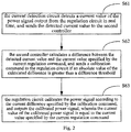
- the current detection circuit detects the current value of the power signal output from the regulation circuit, and sends the detected current value to the second controller.
- step S62 the second controller calculates a difference between the detected current value and the current value specified by the current regulation command, and sends a calibration command to the regulation circuit if an absolute value of the calculated difference is greater than a difference threshold.
- step S63 the regulation circuit calibrates the power signal according to the current difference specified by the calibration command, and outputs a calibrated power signal, in which the current value of the calibrated power signal is equal to the current value specified by the current regulation command.
- the regulation circuit has the current detection circuit, which can detect the current value of the power signal output from the regulation circuit (i.e., the current value of the power signal output from the charging adaptor) in real time.
- the current detection circuit has a current detection resistor, which detects the current value of the power signal output from the regulation circuit in real time and converts the current value to a voltage value, and sends the voltage value to the second controller, such that the second controller determines the current value of the power signal output from the regulation circuit according to the voltage value received and the resistance of the current detection resistor.
- the second controller calculates the difference between the detected current value and the current value specified by the current regulation command, calculates the absolute value of the difference, judges whether the absolute value is greater than the difference threshold, and feeds back the calibration command to the regulation circuit if the absolute value of the calculated difference is greater than the difference threshold, such that the regulation circuit regulates the current value of the power signal outputted therefrom in time according to the calibration command.
- the difference threshold can be adjusted in advance according to actual working environment of the regulation circuit.
- the regulation circuit receives the calibration command, it represents that the deviation of the current value of the power signal outputted by the regulation circuit from the current value specified by the current regulation command is higher, and it is necessary for the regulation circuit to perform the current regulation again.
- the current regulation can be performed according to the current difference specified by the calibration command, thereby ensuring in real time that the current value of the power signal output from the regulation circuit is equal to the current value specified by the current regulation command.
- the regulation circuit also includes a voltage and current regulation circuit.
- the voltage and current regulation circuit performs a rectifying and filtering on the mains supply to obtain an original power signal.
- the regulation circuit determines a voltage regulation command according to the current difference specified by the calibration command, and sends the voltage regulation command to the voltage and current regulation circuit.
- the voltage and current regulation circuit performs the voltage regulation according to the voltage regulation command and outputs the power signal after voltage regulation.
- the current value of the power signal after voltage regulation can be re-detected with the current detection resistor for confirming whether the current value of the power signal is equal to the current value specified by the current regulation command.
- the regulation circuit stops determining the voltage regulation command according to the received calibration command and stops sending the determined voltage regulation command to the voltage and current regulation circuit, and the voltage and current regulation circuit stops performing the voltage regulation.
- the current detection resistor is used to detect in real time, and when the detected current value is too high or too low, the detected current value is fed back to the second controller.
- the second controller generates the calibration command according to the current value fed back and sends the calibration command to the regulation circuit.
- the regulation circuit determines the voltage regulation command according to the calibration command and sends the voltage regulation command to the voltage and current regulation circuit.
- the voltage and current regulation circuit performs the voltage regulation according to the voltage regulation command, and outputs the power signal after the voltage regulation. Then, it is able to further detect with the current detection resistor whether the current value of the power signal after the voltage regulation is equal to the current value specified by the current regulation command.
- Fig. 3 shows a second specific process of the quick charging method provided by embodiments of the present disclosure, and for illustration, only parts related to embodiments of the present disclosure is shown, which is described in detail as follows.
- the quick charging method after the step that the regulation circuit performs the current regulation according to the current regulation command and outputs the power signal after the current regulation, the quick charging method also includes following steps.
- step S7 the charging adaptor sends the power signal via a second charging interface thereof to a first charging interface of the mobile terminal, so as to charge the cell of the mobile terminal, in which first power wires of the first charging interface are coupled to second power wires of the second charging interface, and first ground wires of the first charging interface are coupled to second ground wires of the second charging interface, there are P first power wires and Q first ground wires, where P is greater than or equal to 2, and Q is greater than or equal to 2.
- the common MICRO USB interface (including the MICRO USB interface of the charging adaptor, and also including the MICRO USB interface of the mobile terminal) has only one power wire and one ground wire, so that it is only possible to form the charging circuit with the power wire and the ground wire, and in turn, the charging current is usually only hundreds milliampere, and usually not greater than 3 A.
- this embodiment provides the first charging interface that is capable of supporting charging with large current (charging current greater than or equal to 3A).
- the first charging interface has at least two first power wires and at least two first ground wires, therefore, via the first charging interface, the mobile terminal can support charging with large current.
- the charging adaptor coupled to the first charging interface is a conventional charging adaptor such as a charging adaptor using the MICRO USB interface for charging, it is still possible to perform conventional charging (coupling the only power wire and ground wire of the MICRO USB interface to the one first power wire and one first ground wire of the first charging interface correspondingly), which means that only the power wire and ground wire are used to charge the cell.
- P second power wires and Q second ground wires there are P second power wires and Q second ground wires.
- the P first power wires in the first charging interface are correspondingly coupled to the P second power wires in the second charging interface, and the Q first ground wires in the first charging interface are correspondingly coupled to the Q second round wires in the second charging interface.
- the insertion-connected first charging interface and second charging interface can support charging with large current (charging current equal to or greater than 3A).
- the charging adaptor can output the power signal of large current (for example, 4A power signal) to charge the cell of the mobile terminal with large current, when the voltage value of the cell is lower (for example, the voltage value of the cell is less than 4.3V).
- both the power wire and the ground wire of the conventional MICRO USB interface are made of metal copper foil with the electric conductivity less than 20%.
- the first power wires and the first ground wires of the first charging interface, and the second power wires and the second ground wires of the second charging interface are made of phosphor bronze C7025 with the electric conductivity up to 50%, so that in case of using at least two charging circuits (including at least two first power wires, at least two first ground wires, at least two second power wires and at least two second ground wires) to charge the cell of the mobile terminal, the charging current is further increased.
- the first power wires and the first ground wires of the first charging interface, and the second power wires and the second ground wires of the second charging interface provided by embodiments of the present disclosure are made of chromium bronze C18400 with the electric conductivity up to 70%, so that the charging current is further increased.
- the mobile terminal also includes a switch circuit, and the switch circuit is controlled by the first controller to switch on or off.
- the switch circuit is controlled by the first controller to switch on or off.
- the quick charging method also includes following steps.
- the first controller sends a switch-on command to the switch circuit.
- the switch circuit When the switch circuit receives the switch on command, the switch circuit switches on the charging circuit by which the charging adaptor charges the cell via the switch circuit.
- the cell can be charged via the charging circuit already existing in the mobile terminal and also via the switch circuit, thus realizing charging the cell with large current.
- the first controller feeds back the quick charging permission command to the second controller, so as to inform the second controller that: the cell can be charged with large current.
- the first controller also sends the switch-on command to the switch circuit.
- the switch circuit when receiving the switch-on command, is switched on, and further the charging adaptor can charge the cell via the switched on switch circuit while charging the cell of the mobile terminal via the charging circuit already existed in the mobile terminal.
- the quick charging method also includes following steps.
- the first controller determines whether the obtained voltage value of the cell is greater than the switch-off voltage threshold, and sends a switch-off command to the switch circuit if the obtained voltage value of the cell is greater than the switch-off voltage threshold.
- the switch circuit When the switch circuit receives the switch-off command, the switch circuit switches off the charging circuit by which the charging adaptor charges the cell via the switch circuit.
- the cell connector will always detect and obtain the voltage value of the cell in real time, and send the detected voltage value of the cell to the first controller.
- the first controller judges in real time whether the obtained voltage value of the cell is greater than the switch-off voltage threshold, and sends the switch-off command to the switch circuit if the obtained voltage value of the cell is greater than the switch-off voltage threshold.
- the switch circuit is switched off when receiving the switch-off command.
- the charging adaptor can charge the cell of the mobile terminal only via the charging circuit already existed in the mobile terminal, rather than via the switch circuit which is switched off.
- the second controller when the obtained voltage value of the cell is greater than the switch-off voltage threshold, the second controller also sends the current regulation command to the regulation current, in which the current regulation command specifies the power signal of small current (for example, hundreds milliampere) outputted from the regulation circuit.
- the current regulation command specifies the power signal of small current (for example, hundreds milliampere) outputted from the regulation circuit.
- the first controller can be a controller existing in the mobile terminal.
- the mobile terminal not only has a third controller (already configured in the existing mobile terminal) used to handle applications, but also has the first controller.
- the first controller controls the switch circuit and controls charging the cell of the mobile terminal.
- the first controller transmits the voltage value of the cell received in real time to the third controller, and the third controller determines whether the obtained voltage value of the cell is greater than the switch-off voltage threshold. If the obtained voltage value of the cell is greater than the switch-off voltage threshold, the third controller sends a first switch-off command to the first controller, and then the first controller sends the switch-off command to the switch circuit.
- the third controller can directly send the switch-off command to the switch circuit if the obtained voltage value of the cell is greater than the switch-off voltage threshold.
- the switch circuit switches off the charging circuit by which the charging adaptor charges the cell via the switch circuit, when receiving the switch-off command.
- the charging can be performed via the charging circuit already existed in the mobile terminal.
- this embodiment additionally adds a switch circuit into the mobile terminal.
- the second charging interface is insertion-connected with the first charging interface, it is not only able to charge the cell via the charging circuit in the mobile terminal, but also able to control the switch circuit to switch on with the first controller, such that the charging adaptor can charge the cell via the existing charging current and also via the switch circuit which is switched on.
- the cell connector is also configured to generate an anode contact signal when detecting whether an anode of the cell is in contact, to generate a cathode contact signal when detecting whether a cathode of the cell is in contact, to generate a temperature signal when detecting a temperature of the cell, and to send the anode contact signal, the cathode contact signal and the temperature signal to the first controller.
- the first controller transmits the anode contact signal, the cathode contact signal and the temperature signal to the third controller.
- the third controller determines whether a positive charging contact point of the charging circuit and the switch circuit of the mobile terminal is in good contact with the anode of the cell according to the received anode contact signal, determines whether a negative charging contact point of the charging circuit and the switch circuit of the mobile terminal is in good contact with the cathode of the cell according to the received cathode contact signal, and determines whether the temperature of the cell exceeds a temperature threshold according to the temperature signal.
- the third controller is configured to send the first switch-off command to the first controller, if it is determined that the positive charging contact point is not in good contact with the anode of the cell according to the received anode contact signal, or if it is determined that the negative charging contact point is not in good contact with the cathode of the cell according to the cathode contact signal, or if it is determined that the temperature of the cell has exceeded the temperature threshold according to the temperature signal.
- the first controller sends the switch-off command to the switch circuit to switch off the switch circuit, which stops the charging adaptor from charging the cell via the switch circuit.
- Fig. 4 shows a first block diagram of a quick charging system provided by an embodiment of the present disclosure, and for illustration, only parts related to the embodiments of the present disclosure are shown, which is described in detail as follows.
- the quick charging system includes a charging adaptor 2 having a second controller 21 and a regulation circuit 22, and a mobile terminal 1 having a cell connector, a first controller 11 and a cell.
- the second controller 21 is configured to send a quick charging request to the first controller 11, to send a notification request for obtaining a voltage value of the cell to the first controller 11, to search a threshold range table for a current regulation command matched with a threshold range containing the voltage value of the cell, and to send the current regulation command to the regulation circuit 22.
- the charging adaptor 2 includes the regulation circuit 22, and the threshold range table records one or more threshold ranges and current regulation commands having a mapping relation with the threshold ranges.
- the first controller 11 is configured to respond to the quick charging request of the second controller 21, to feed back a quick charging permission command to the second controller 21, to respond to the notification request, to obtain the voltage value of the cell via the cell connector, and to send the obtained voltage value of the cell to the second controller 21.
- the regulation circuit 22 is configured to perform the current regulation according to the current regulation command, and to output the power signal after the current regulation.
- Fig. 5 shows a second block diagram of the quick charging system provided by an embodiment of the disclosure, and for illustration, only parts related to embodiments of the disclosure are shown, which is described in detail as follows.
- the regulation circuit 22 includes a current detection circuit 221.
- the current detection circuit 221 is configured to detect a current value of the power signal output from the regulation circuit 22, and to send the detected current value to the second controller 21.
- the second controller 21 is also configured to calculate a difference between the detected current value and the current value specified by the current regulation command, and to send a calibration command to the regulation circuit 22 if an absolute value of the calculated difference is greater than a difference threshold.
- the regulation circuit 22 is also configured to calibrate the power signal according to the current difference specified by the calibration command, and to output the calibrated power signal, in which the current value of the calibrated power signal is equal to the current value specified by the current regulation command.
- Fig. 6 shows a third block diagram of the quick charging system provided by an embodiment of the present disclosure, and for illustration, only parts related to embodiments of the present disclosure are shown, which is described in detail as follows.
- the charging adaptor 2 further includes a second charging interface 23, and the mobile terminal 1 further includes a first charging interface 12.
- the charging adaptor 2 is further configured to send the power signal via the second charging interface 23 to the first charging interface 12, so as to charge the cell of the mobile terminal 1.
- the first power wires of the first charging interface 12 are coupled to the second power wires of the second charging interface 23, and the first ground wires of the first charging interface 12 are coupled to the second ground wires of the second charging interface 23.
- the number of the first power wires is P and the number of the first ground wires is Q, where P is greater than or equal to 2, and Q is greater than or equal to 2.
- the number of the second power wires is P and the number of the second ground wires is Q.
- the P first power wires in the first charging interface 12 are correspondingly coupled to the P second power wires in the second charging interface 23, and the Q first ground wires in the first charging interface 12 are correspondingly coupled to the Q second round wires in the second charging interface 23.
- Fig. 7 shows a fourth block diagram of the quick charging system provided by an embodiment of the present disclosure, and for illustration, only parts related to embodiments of the present disclosure are shown, which is described in detail as follows.
- the mobile terminal 1 further includes a switch circuit 13.
- the first controller 11 is further configured to send a switch-on command to the switch circuit 13, and further configured to determine whether the obtained voltage value of the cell is greater than a switch-off voltage threshold, and to send a switch-off command to the switch circuit 13 if the obtained voltage value of the cell is greater than the switch-off voltage threshold.
- the switch circuit 13 is configured to switch on the charging circuit by which the charging adaptor 2 charges the cell via the switch circuit 13 when receiving the switch-on command, and further configured to switch off the charging circuit by which the charging adaptor 2 charges the cell via the switching circuit 13, when receiving the switch-off command.
Priority Applications (1)
| Application Number | Priority Date | Filing Date | Title |
|---|---|---|---|
| PL18172892T PL3379690T3 (pl) | 2014-01-28 | 2014-05-14 | Sposób i system szybkiego ładowania |
Applications Claiming Priority (3)
| Application Number | Priority Date | Filing Date | Title |
|---|---|---|---|
| CN201410043242.9A CN104810879B (zh) | 2014-01-28 | 2014-01-28 | 快速充电方法和系统 |
| EP14880476.8A EP3101751B1 (de) | 2014-01-28 | 2014-05-14 | Schnellaufladeverfahren und system |
| PCT/CN2014/077490 WO2015113345A1 (zh) | 2014-01-28 | 2014-05-14 | 快速充电方法和系统 |
Related Parent Applications (2)
| Application Number | Title | Priority Date | Filing Date |
|---|---|---|---|
| EP14880476.8A Division EP3101751B1 (de) | 2014-01-28 | 2014-05-14 | Schnellaufladeverfahren und system |
| EP14880476.8A Division-Into EP3101751B1 (de) | 2014-01-28 | 2014-05-14 | Schnellaufladeverfahren und system |
Publications (2)
| Publication Number | Publication Date |
|---|---|
| EP3379690A1 true EP3379690A1 (de) | 2018-09-26 |
| EP3379690B1 EP3379690B1 (de) | 2019-05-01 |
Family
ID=53695481
Family Applications (2)
| Application Number | Title | Priority Date | Filing Date |
|---|---|---|---|
| EP14880476.8A Active EP3101751B1 (de) | 2014-01-28 | 2014-05-14 | Schnellaufladeverfahren und system |
| EP18172892.4A Active EP3379690B1 (de) | 2014-01-28 | 2014-05-14 | Schnellaufladeverfahren und -system |
Family Applications Before (1)
| Application Number | Title | Priority Date | Filing Date |
|---|---|---|---|
| EP14880476.8A Active EP3101751B1 (de) | 2014-01-28 | 2014-05-14 | Schnellaufladeverfahren und system |
Country Status (9)
| Country | Link |
|---|---|
| US (2) | US9935479B2 (de) |
| EP (2) | EP3101751B1 (de) |
| CN (2) | CN106487065B (de) |
| DK (2) | DK3379690T3 (de) |
| ES (2) | ES2732784T3 (de) |
| HU (2) | HUE045019T2 (de) |
| PL (2) | PL3101751T3 (de) |
| PT (2) | PT3101751T (de) |
| WO (1) | WO2015113345A1 (de) |
Families Citing this family (20)
| Publication number | Priority date | Publication date | Assignee | Title |
|---|---|---|---|---|
| CN103746434B (zh) * | 2014-01-28 | 2016-04-06 | 广东欧珀移动通信有限公司 | 充电方法和系统 |
| CN106487065B (zh) * | 2014-01-28 | 2019-02-05 | Oppo广东移动通信有限公司 | 快速充电方法和系统 |
| CN104600796B (zh) * | 2014-12-30 | 2019-09-20 | 惠州Tcl移动通信有限公司 | 快速充电的移动终端及方法、系统 |
| CN108390433B (zh) * | 2015-05-13 | 2022-01-11 | Oppo广东移动通信有限公司 | 快速充电方法、电源适配器和移动终端 |
| CN105071473B (zh) * | 2015-08-11 | 2018-07-24 | 小米科技有限责任公司 | Usb充电方法及装置 |
| CN107210615B (zh) * | 2016-01-05 | 2019-09-13 | Oppo广东移动通信有限公司 | 快速充电方法、移动终端和适配器 |
| CN105870991A (zh) * | 2016-01-30 | 2016-08-17 | 乐视致新电子科技(天津)有限公司 | 一种支持多电池快速充电的设备、装置及方法 |
| SG11201700428UA (en) * | 2016-02-05 | 2017-09-28 | Guangdong Oppo Mobile Telecommunications Corp Ltd | Charge method, adapter and mobile terminal |
| KR102157331B1 (ko) * | 2016-02-05 | 2020-09-17 | 광동 오포 모바일 텔레커뮤니케이션즈 코포레이션 리미티드 | 어댑터 및 충전 제어 방법 |
| CN105826979A (zh) * | 2016-04-27 | 2016-08-03 | 乐视控股(北京)有限公司 | 充电匹配方法、装置、电子设备及pd充电器 |
| CN106100056A (zh) * | 2016-07-28 | 2016-11-09 | 广东欧珀移动通信有限公司 | 电源适配器及移动终端 |
| CN106207296B (zh) * | 2016-08-25 | 2020-05-19 | 上海传英信息技术有限公司 | 充电方法 |
| TWI616048B (zh) * | 2017-02-16 | 2018-02-21 | 江蘇辰陽電子有限公司 | 充電控制系統及其運作方法 |
| CN106911157B (zh) * | 2017-02-28 | 2023-12-12 | 深圳罗马仕科技有限公司 | 快充线、快充系统及快充方法 |
| EP3709472A4 (de) | 2018-09-06 | 2021-02-17 | Guangdong Oppo Mobile Telecommunications Corp., Ltd. | Laderegelungsverfahren, endgerät und computerspeichermedium |
| CN110718951B (zh) * | 2019-11-06 | 2021-10-08 | 广州极飞科技股份有限公司 | 充电控制方法、装置、充电器和计算机可读存储介质 |
| CN110829536A (zh) * | 2019-11-21 | 2020-02-21 | 恩力能源科技有限公司 | 一种智能电池充电器的安全冗余控制装置及方法 |
| TWI742582B (zh) * | 2020-03-24 | 2021-10-11 | 廣達電腦股份有限公司 | 充電裝置及其方法 |
| CN112737019A (zh) * | 2020-12-24 | 2021-04-30 | 联想(北京)有限公司 | 一种充电控制方法及装置 |
| CN117856366A (zh) * | 2022-09-30 | 2024-04-09 | 荣耀终端有限公司 | 一种手表、充电底座以及充电系统 |
Citations (3)
| Publication number | Priority date | Publication date | Assignee | Title |
|---|---|---|---|---|
| US20050174094A1 (en) * | 2004-02-11 | 2005-08-11 | Research In Motion Limited, A Canadian Corporation | Battery charger for portable devices and related methods |
| US20110037438A1 (en) * | 2009-08-17 | 2011-02-17 | Apple Inc. | Modulated, temperature-based multi-cc-cv charging technique for li-ion/li-polymer batteries |
| CN103236568A (zh) * | 2013-05-03 | 2013-08-07 | 深圳市中兴移动通信有限公司 | 充电方法和充电系统 |
Family Cites Families (12)
| Publication number | Priority date | Publication date | Assignee | Title |
|---|---|---|---|---|
| US6137265A (en) * | 1999-01-11 | 2000-10-24 | Dell Usa, L.P. | Adaptive fast charging of lithium-ion batteries |
| JP2007228643A (ja) * | 2006-02-21 | 2007-09-06 | Meidensha Corp | Acアダプタ |
| CN101414753A (zh) * | 2007-10-19 | 2009-04-22 | 英华达(南京)科技有限公司 | 具有限流充电功能的移动通信装置 |
| KR100848297B1 (ko) * | 2007-12-24 | 2008-07-25 | (주)시그넷시스템 | 병렬운전 통합 및 분산 제어가 가능한 충전기 |
| WO2010028368A1 (en) * | 2008-09-08 | 2010-03-11 | Techtronic Power Tools Technology Limited | Battery charger |
| US8319470B2 (en) * | 2010-02-12 | 2012-11-27 | Suncore, Inc. | Stand alone solar battery charger |
| CN102570546B (zh) * | 2011-12-28 | 2016-07-27 | 中兴通讯股份有限公司 | 一种移动终端及其充电设备、方法 |
| CN102957193B (zh) * | 2012-11-19 | 2015-12-23 | 中兴通讯股份有限公司 | 一种充电管理方法、装置和系统 |
| JP5495407B1 (ja) * | 2012-12-21 | 2014-05-21 | パナソニック株式会社 | 電子機器、充電器及び電子機器システム |
| CN103178595B (zh) * | 2013-03-14 | 2015-06-24 | 广东欧珀移动通信有限公司 | 手机适配器 |
| CN104810909B (zh) * | 2014-01-28 | 2016-09-28 | 广东欧珀移动通信有限公司 | 快速充电控制方法和系统 |
| CN106487065B (zh) * | 2014-01-28 | 2019-02-05 | Oppo广东移动通信有限公司 | 快速充电方法和系统 |
-
2014
- 2014-01-28 CN CN201611028570.7A patent/CN106487065B/zh active Active
- 2014-01-28 CN CN201410043242.9A patent/CN104810879B/zh active Active
- 2014-05-14 HU HUE18172892A patent/HUE045019T2/hu unknown
- 2014-05-14 PL PL14880476T patent/PL3101751T3/pl unknown
- 2014-05-14 ES ES18172892T patent/ES2732784T3/es active Active
- 2014-05-14 PL PL18172892T patent/PL3379690T3/pl unknown
- 2014-05-14 DK DK18172892.4T patent/DK3379690T3/da active
- 2014-05-14 HU HUE14880476A patent/HUE040180T2/hu unknown
- 2014-05-14 PT PT14880476T patent/PT3101751T/pt unknown
- 2014-05-14 EP EP14880476.8A patent/EP3101751B1/de active Active
- 2014-05-14 ES ES14880476.8T patent/ES2694140T3/es active Active
- 2014-05-14 PT PT18172892T patent/PT3379690T/pt unknown
- 2014-05-14 WO PCT/CN2014/077490 patent/WO2015113345A1/zh active Application Filing
- 2014-05-14 EP EP18172892.4A patent/EP3379690B1/de active Active
- 2014-05-14 DK DK14880476.8T patent/DK3101751T3/en active
- 2014-05-14 US US15/115,000 patent/US9935479B2/en active Active
-
2018
- 2018-02-13 US US15/895,127 patent/US10148113B2/en active Active
Patent Citations (3)
| Publication number | Priority date | Publication date | Assignee | Title |
|---|---|---|---|---|
| US20050174094A1 (en) * | 2004-02-11 | 2005-08-11 | Research In Motion Limited, A Canadian Corporation | Battery charger for portable devices and related methods |
| US20110037438A1 (en) * | 2009-08-17 | 2011-02-17 | Apple Inc. | Modulated, temperature-based multi-cc-cv charging technique for li-ion/li-polymer batteries |
| CN103236568A (zh) * | 2013-05-03 | 2013-08-07 | 深圳市中兴移动通信有限公司 | 充电方法和充电系统 |
Also Published As
| Publication number | Publication date |
|---|---|
| US20180175637A1 (en) | 2018-06-21 |
| DK3379690T3 (da) | 2019-07-01 |
| WO2015113345A1 (zh) | 2015-08-06 |
| CN106487065B (zh) | 2019-02-05 |
| CN106487065A (zh) | 2017-03-08 |
| CN104810879A (zh) | 2015-07-29 |
| EP3101751A4 (de) | 2017-10-18 |
| HUE040180T2 (hu) | 2019-02-28 |
| ES2694140T3 (es) | 2018-12-18 |
| PL3101751T3 (pl) | 2018-12-31 |
| DK3101751T3 (en) | 2018-10-08 |
| CN104810879B (zh) | 2016-12-14 |
| US10148113B2 (en) | 2018-12-04 |
| EP3379690B1 (de) | 2019-05-01 |
| EP3101751B1 (de) | 2018-08-22 |
| PT3379690T (pt) | 2019-07-08 |
| ES2732784T3 (es) | 2019-11-25 |
| HUE045019T2 (hu) | 2019-12-30 |
| US9935479B2 (en) | 2018-04-03 |
| US20160344200A1 (en) | 2016-11-24 |
| PL3379690T3 (pl) | 2019-09-30 |
| PT3101751T (pt) | 2018-10-29 |
| EP3101751A1 (de) | 2016-12-07 |
Similar Documents
| Publication | Publication Date | Title |
|---|---|---|
| US10148113B2 (en) | Charging method, device and charging device | |
| US10714950B2 (en) | Charging control method and charging device | |
| US10447058B2 (en) | Charging method and system | |
| EP3413428A1 (de) | Ladevorrichtung, endgerätevorrichtung und ladesystem | |
| CN105846527A (zh) | 电源适配器、充电单元、电子设备及其组件、及充电方法 |
Legal Events
| Date | Code | Title | Description |
|---|---|---|---|
| PUAI | Public reference made under article 153(3) epc to a published international application that has entered the european phase |
Free format text: ORIGINAL CODE: 0009012 |
|
| STAA | Information on the status of an ep patent application or granted ep patent |
Free format text: STATUS: THE APPLICATION HAS BEEN PUBLISHED |
|
| AC | Divisional application: reference to earlier application |
Ref document number: 3101751 Country of ref document: EP Kind code of ref document: P |
|
| AK | Designated contracting states |
Kind code of ref document: A1 Designated state(s): AL AT BE BG CH CY CZ DE DK EE ES FI FR GB GR HR HU IE IS IT LI LT LU LV MC MK MT NL NO PL PT RO RS SE SI SK SM TR |
|
| STAA | Information on the status of an ep patent application or granted ep patent |
Free format text: STATUS: REQUEST FOR EXAMINATION WAS MADE |
|
| 17P | Request for examination filed |
Effective date: 20181031 |
|
| RBV | Designated contracting states (corrected) |
Designated state(s): AL AT BE BG CH CY CZ DE DK EE ES FI FR GB GR HR HU IE IS IT LI LT LU LV MC MK MT NL NO PL PT RO RS SE SI SK SM TR |
|
| GRAP | Despatch of communication of intention to grant a patent |
Free format text: ORIGINAL CODE: EPIDOSNIGR1 |
|
| STAA | Information on the status of an ep patent application or granted ep patent |
Free format text: STATUS: GRANT OF PATENT IS INTENDED |
|
| INTG | Intention to grant announced |
Effective date: 20181221 |
|
| GRAS | Grant fee paid |
Free format text: ORIGINAL CODE: EPIDOSNIGR3 |
|
| GRAA | (expected) grant |
Free format text: ORIGINAL CODE: 0009210 |
|
| STAA | Information on the status of an ep patent application or granted ep patent |
Free format text: STATUS: THE PATENT HAS BEEN GRANTED |
|
| RAP1 | Party data changed (applicant data changed or rights of an application transferred) |
Owner name: GUANGDONG OPPO MOBILE TELECOMMUNICATIONS CORP., LT |
|
| AC | Divisional application: reference to earlier application |
Ref document number: 3101751 Country of ref document: EP Kind code of ref document: P |
|
| AK | Designated contracting states |
Kind code of ref document: B1 Designated state(s): AL AT BE BG CH CY CZ DE DK EE ES FI FR GB GR HR HU IE IS IT LI LT LU LV MC MK MT NL NO PL PT RO RS SE SI SK SM TR |
|
| REG | Reference to a national code |
Ref country code: GB Ref legal event code: FG4D |
|
| REG | Reference to a national code |
Ref country code: CH Ref legal event code: EP Ref country code: AT Ref legal event code: REF Ref document number: 1128213 Country of ref document: AT Kind code of ref document: T Effective date: 20190515 |
|
| REG | Reference to a national code |
Ref country code: DE Ref legal event code: R096 Ref document number: 602014046077 Country of ref document: DE |
|
| REG | Reference to a national code |
Ref country code: IE Ref legal event code: FG4D |
|
| REG | Reference to a national code |
Ref country code: DK Ref legal event code: T3 Effective date: 20190624 |
|
| REG | Reference to a national code |
Ref country code: PT Ref legal event code: SC4A Ref document number: 3379690 Country of ref document: PT Date of ref document: 20190708 Kind code of ref document: T Free format text: AVAILABILITY OF NATIONAL TRANSLATION Effective date: 20190625 |
|
| REG | Reference to a national code |
Ref country code: SE Ref legal event code: TRGR |
|
| REG | Reference to a national code |
Ref country code: NL Ref legal event code: FP |
|
| REG | Reference to a national code |
Ref country code: NO Ref legal event code: T2 Effective date: 20190501 |
|
| REG | Reference to a national code |
Ref country code: LT Ref legal event code: MG4D |
|
| REG | Reference to a national code |
Ref country code: GR Ref legal event code: EP Ref document number: 20190401827 Country of ref document: GR Effective date: 20190906 |
|
| PG25 | Lapsed in a contracting state [announced via postgrant information from national office to epo] |
Ref country code: AL Free format text: LAPSE BECAUSE OF FAILURE TO SUBMIT A TRANSLATION OF THE DESCRIPTION OR TO PAY THE FEE WITHIN THE PRESCRIBED TIME-LIMIT Effective date: 20190501 Ref country code: HR Free format text: LAPSE BECAUSE OF FAILURE TO SUBMIT A TRANSLATION OF THE DESCRIPTION OR TO PAY THE FEE WITHIN THE PRESCRIBED TIME-LIMIT Effective date: 20190501 Ref country code: LT Free format text: LAPSE BECAUSE OF FAILURE TO SUBMIT A TRANSLATION OF THE DESCRIPTION OR TO PAY THE FEE WITHIN THE PRESCRIBED TIME-LIMIT Effective date: 20190501 |
|
| REG | Reference to a national code |
Ref country code: ES Ref legal event code: FG2A Ref document number: 2732784 Country of ref document: ES Kind code of ref document: T3 Effective date: 20191125 |
|
| PG25 | Lapsed in a contracting state [announced via postgrant information from national office to epo] |
Ref country code: BG Free format text: LAPSE BECAUSE OF FAILURE TO SUBMIT A TRANSLATION OF THE DESCRIPTION OR TO PAY THE FEE WITHIN THE PRESCRIBED TIME-LIMIT Effective date: 20190801 Ref country code: RS Free format text: LAPSE BECAUSE OF FAILURE TO SUBMIT A TRANSLATION OF THE DESCRIPTION OR TO PAY THE FEE WITHIN THE PRESCRIBED TIME-LIMIT Effective date: 20190501 Ref country code: LV Free format text: LAPSE BECAUSE OF FAILURE TO SUBMIT A TRANSLATION OF THE DESCRIPTION OR TO PAY THE FEE WITHIN THE PRESCRIBED TIME-LIMIT Effective date: 20190501 |
|
| RAP2 | Party data changed (patent owner data changed or rights of a patent transferred) |
Owner name: GUANGDONG OPPO MOBILE TELECOMMUNICATIONS CORP., LT |
|
| REG | Reference to a national code |
Ref country code: HU Ref legal event code: AG4A Ref document number: E045019 Country of ref document: HU |
|
| PG25 | Lapsed in a contracting state [announced via postgrant information from national office to epo] |
Ref country code: IS Free format text: LAPSE BECAUSE OF FAILURE TO SUBMIT A TRANSLATION OF THE DESCRIPTION OR TO PAY THE FEE WITHIN THE PRESCRIBED TIME-LIMIT Effective date: 20190901 |
|
| PG25 | Lapsed in a contracting state [announced via postgrant information from national office to epo] |
Ref country code: CZ Free format text: LAPSE BECAUSE OF FAILURE TO SUBMIT A TRANSLATION OF THE DESCRIPTION OR TO PAY THE FEE WITHIN THE PRESCRIBED TIME-LIMIT Effective date: 20190501 Ref country code: RO Free format text: LAPSE BECAUSE OF FAILURE TO SUBMIT A TRANSLATION OF THE DESCRIPTION OR TO PAY THE FEE WITHIN THE PRESCRIBED TIME-LIMIT Effective date: 20190501 Ref country code: EE Free format text: LAPSE BECAUSE OF FAILURE TO SUBMIT A TRANSLATION OF THE DESCRIPTION OR TO PAY THE FEE WITHIN THE PRESCRIBED TIME-LIMIT Effective date: 20190501 Ref country code: MC Free format text: LAPSE BECAUSE OF FAILURE TO SUBMIT A TRANSLATION OF THE DESCRIPTION OR TO PAY THE FEE WITHIN THE PRESCRIBED TIME-LIMIT Effective date: 20190501 Ref country code: SK Free format text: LAPSE BECAUSE OF FAILURE TO SUBMIT A TRANSLATION OF THE DESCRIPTION OR TO PAY THE FEE WITHIN THE PRESCRIBED TIME-LIMIT Effective date: 20190501 |
|
| REG | Reference to a national code |
Ref country code: DE Ref legal event code: R097 Ref document number: 602014046077 Country of ref document: DE |
|
| PG25 | Lapsed in a contracting state [announced via postgrant information from national office to epo] |
Ref country code: LU Free format text: LAPSE BECAUSE OF NON-PAYMENT OF DUE FEES Effective date: 20190514 Ref country code: SM Free format text: LAPSE BECAUSE OF FAILURE TO SUBMIT A TRANSLATION OF THE DESCRIPTION OR TO PAY THE FEE WITHIN THE PRESCRIBED TIME-LIMIT Effective date: 20190501 |
|
| PLBE | No opposition filed within time limit |
Free format text: ORIGINAL CODE: 0009261 |
|
| STAA | Information on the status of an ep patent application or granted ep patent |
Free format text: STATUS: NO OPPOSITION FILED WITHIN TIME LIMIT |
|
| PG25 | Lapsed in a contracting state [announced via postgrant information from national office to epo] |
Ref country code: TR Free format text: LAPSE BECAUSE OF FAILURE TO SUBMIT A TRANSLATION OF THE DESCRIPTION OR TO PAY THE FEE WITHIN THE PRESCRIBED TIME-LIMIT Effective date: 20190501 |
|
| 26N | No opposition filed |
Effective date: 20200204 |
|
| REG | Reference to a national code |
Ref country code: AT Ref legal event code: UEP Ref document number: 1128213 Country of ref document: AT Kind code of ref document: T Effective date: 20190501 |
|
| PG25 | Lapsed in a contracting state [announced via postgrant information from national office to epo] |
Ref country code: CY Free format text: LAPSE BECAUSE OF FAILURE TO SUBMIT A TRANSLATION OF THE DESCRIPTION OR TO PAY THE FEE WITHIN THE PRESCRIBED TIME-LIMIT Effective date: 20190501 |
|
| PG25 | Lapsed in a contracting state [announced via postgrant information from national office to epo] |
Ref country code: MT Free format text: LAPSE BECAUSE OF FAILURE TO SUBMIT A TRANSLATION OF THE DESCRIPTION OR TO PAY THE FEE WITHIN THE PRESCRIBED TIME-LIMIT Effective date: 20190501 |
|
| PG25 | Lapsed in a contracting state [announced via postgrant information from national office to epo] |
Ref country code: SI Free format text: LAPSE BECAUSE OF FAILURE TO SUBMIT A TRANSLATION OF THE DESCRIPTION OR TO PAY THE FEE WITHIN THE PRESCRIBED TIME-LIMIT Effective date: 20190501 |
|
| PG25 | Lapsed in a contracting state [announced via postgrant information from national office to epo] |
Ref country code: MK Free format text: LAPSE BECAUSE OF FAILURE TO SUBMIT A TRANSLATION OF THE DESCRIPTION OR TO PAY THE FEE WITHIN THE PRESCRIBED TIME-LIMIT Effective date: 20190501 |
|
| P01 | Opt-out of the competence of the unified patent court (upc) registered |
Effective date: 20230412 |
|
| PGFP | Annual fee paid to national office [announced via postgrant information from national office to epo] |
Ref country code: NL Payment date: 20230427 Year of fee payment: 10 |
|
| PGFP | Annual fee paid to national office [announced via postgrant information from national office to epo] |
Ref country code: PT Payment date: 20230417 Year of fee payment: 10 Ref country code: NO Payment date: 20230426 Year of fee payment: 10 Ref country code: IT Payment date: 20230523 Year of fee payment: 10 Ref country code: IE Payment date: 20230424 Year of fee payment: 10 Ref country code: FR Payment date: 20230523 Year of fee payment: 10 Ref country code: ES Payment date: 20230607 Year of fee payment: 10 Ref country code: DK Payment date: 20230427 Year of fee payment: 10 Ref country code: DE Payment date: 20230510 Year of fee payment: 10 Ref country code: CH Payment date: 20230602 Year of fee payment: 10 |
|
| PGFP | Annual fee paid to national office [announced via postgrant information from national office to epo] |
Ref country code: SE Payment date: 20230512 Year of fee payment: 10 Ref country code: PL Payment date: 20230504 Year of fee payment: 10 Ref country code: HU Payment date: 20230426 Year of fee payment: 10 Ref country code: GR Payment date: 20230420 Year of fee payment: 10 Ref country code: FI Payment date: 20230421 Year of fee payment: 10 Ref country code: AT Payment date: 20230421 Year of fee payment: 10 |
|
| PGFP | Annual fee paid to national office [announced via postgrant information from national office to epo] |
Ref country code: BE Payment date: 20230515 Year of fee payment: 10 |
|
| PGFP | Annual fee paid to national office [announced via postgrant information from national office to epo] |
Ref country code: GB Payment date: 20230519 Year of fee payment: 10 |