EP3379684A1 - Remaining battery capacity display device, battery system and remaining battery capacity display method - Google Patents
Remaining battery capacity display device, battery system and remaining battery capacity display method Download PDFInfo
- Publication number
- EP3379684A1 EP3379684A1 EP16866170.0A EP16866170A EP3379684A1 EP 3379684 A1 EP3379684 A1 EP 3379684A1 EP 16866170 A EP16866170 A EP 16866170A EP 3379684 A1 EP3379684 A1 EP 3379684A1
- Authority
- EP
- European Patent Office
- Prior art keywords
- display
- remaining capacity
- individual
- battery
- capacities
- Prior art date
- Legal status (The legal status is an assumption and is not a legal conclusion. Google has not performed a legal analysis and makes no representation as to the accuracy of the status listed.)
- Granted
Links
Images


Classifications
-
- B—PERFORMING OPERATIONS; TRANSPORTING
- B60—VEHICLES IN GENERAL
- B60L—PROPULSION OF ELECTRICALLY-PROPELLED VEHICLES; SUPPLYING ELECTRIC POWER FOR AUXILIARY EQUIPMENT OF ELECTRICALLY-PROPELLED VEHICLES; ELECTRODYNAMIC BRAKE SYSTEMS FOR VEHICLES IN GENERAL; MAGNETIC SUSPENSION OR LEVITATION FOR VEHICLES; MONITORING OPERATING VARIABLES OF ELECTRICALLY-PROPELLED VEHICLES; ELECTRIC SAFETY DEVICES FOR ELECTRICALLY-PROPELLED VEHICLES
- B60L53/00—Methods of charging batteries, specially adapted for electric vehicles; Charging stations or on-board charging equipment therefor; Exchange of energy storage elements in electric vehicles
- B60L53/80—Exchanging energy storage elements, e.g. removable batteries
-
- B—PERFORMING OPERATIONS; TRANSPORTING
- B60—VEHICLES IN GENERAL
- B60K—ARRANGEMENT OR MOUNTING OF PROPULSION UNITS OR OF TRANSMISSIONS IN VEHICLES; ARRANGEMENT OR MOUNTING OF PLURAL DIVERSE PRIME-MOVERS IN VEHICLES; AUXILIARY DRIVES FOR VEHICLES; INSTRUMENTATION OR DASHBOARDS FOR VEHICLES; ARRANGEMENTS IN CONNECTION WITH COOLING, AIR INTAKE, GAS EXHAUST OR FUEL SUPPLY OF PROPULSION UNITS IN VEHICLES
- B60K35/00—Instruments specially adapted for vehicles; Arrangement of instruments in or on vehicles
- B60K35/10—Input arrangements, i.e. from user to vehicle, associated with vehicle functions or specially adapted therefor
-
- B—PERFORMING OPERATIONS; TRANSPORTING
- B60—VEHICLES IN GENERAL
- B60K—ARRANGEMENT OR MOUNTING OF PROPULSION UNITS OR OF TRANSMISSIONS IN VEHICLES; ARRANGEMENT OR MOUNTING OF PLURAL DIVERSE PRIME-MOVERS IN VEHICLES; AUXILIARY DRIVES FOR VEHICLES; INSTRUMENTATION OR DASHBOARDS FOR VEHICLES; ARRANGEMENTS IN CONNECTION WITH COOLING, AIR INTAKE, GAS EXHAUST OR FUEL SUPPLY OF PROPULSION UNITS IN VEHICLES
- B60K35/00—Instruments specially adapted for vehicles; Arrangement of instruments in or on vehicles
- B60K35/20—Output arrangements, i.e. from vehicle to user, associated with vehicle functions or specially adapted therefor
- B60K35/21—Output arrangements, i.e. from vehicle to user, associated with vehicle functions or specially adapted therefor using visual output, e.g. blinking lights or matrix displays
- B60K35/22—Display screens
-
- B—PERFORMING OPERATIONS; TRANSPORTING
- B60—VEHICLES IN GENERAL
- B60K—ARRANGEMENT OR MOUNTING OF PROPULSION UNITS OR OF TRANSMISSIONS IN VEHICLES; ARRANGEMENT OR MOUNTING OF PLURAL DIVERSE PRIME-MOVERS IN VEHICLES; AUXILIARY DRIVES FOR VEHICLES; INSTRUMENTATION OR DASHBOARDS FOR VEHICLES; ARRANGEMENTS IN CONNECTION WITH COOLING, AIR INTAKE, GAS EXHAUST OR FUEL SUPPLY OF PROPULSION UNITS IN VEHICLES
- B60K35/00—Instruments specially adapted for vehicles; Arrangement of instruments in or on vehicles
- B60K35/80—Arrangements for controlling instruments
- B60K35/81—Arrangements for controlling instruments for controlling displays
-
- B—PERFORMING OPERATIONS; TRANSPORTING
- B60—VEHICLES IN GENERAL
- B60L—PROPULSION OF ELECTRICALLY-PROPELLED VEHICLES; SUPPLYING ELECTRIC POWER FOR AUXILIARY EQUIPMENT OF ELECTRICALLY-PROPELLED VEHICLES; ELECTRODYNAMIC BRAKE SYSTEMS FOR VEHICLES IN GENERAL; MAGNETIC SUSPENSION OR LEVITATION FOR VEHICLES; MONITORING OPERATING VARIABLES OF ELECTRICALLY-PROPELLED VEHICLES; ELECTRIC SAFETY DEVICES FOR ELECTRICALLY-PROPELLED VEHICLES
- B60L58/00—Methods or circuit arrangements for monitoring or controlling batteries or fuel cells, specially adapted for electric vehicles
- B60L58/10—Methods or circuit arrangements for monitoring or controlling batteries or fuel cells, specially adapted for electric vehicles for monitoring or controlling batteries
-
- B—PERFORMING OPERATIONS; TRANSPORTING
- B60—VEHICLES IN GENERAL
- B60R—VEHICLES, VEHICLE FITTINGS, OR VEHICLE PARTS, NOT OTHERWISE PROVIDED FOR
- B60R16/00—Electric or fluid circuits specially adapted for vehicles and not otherwise provided for; Arrangement of elements of electric or fluid circuits specially adapted for vehicles and not otherwise provided for
- B60R16/02—Electric or fluid circuits specially adapted for vehicles and not otherwise provided for; Arrangement of elements of electric or fluid circuits specially adapted for vehicles and not otherwise provided for electric constitutive elements
-
- H—ELECTRICITY
- H01—ELECTRIC ELEMENTS
- H01M—PROCESSES OR MEANS, e.g. BATTERIES, FOR THE DIRECT CONVERSION OF CHEMICAL ENERGY INTO ELECTRICAL ENERGY
- H01M10/00—Secondary cells; Manufacture thereof
- H01M10/42—Methods or arrangements for servicing or maintenance of secondary cells or secondary half-cells
- H01M10/48—Accumulators combined with arrangements for measuring, testing or indicating the condition of cells, e.g. the level or density of the electrolyte
-
- H—ELECTRICITY
- H01—ELECTRIC ELEMENTS
- H01M—PROCESSES OR MEANS, e.g. BATTERIES, FOR THE DIRECT CONVERSION OF CHEMICAL ENERGY INTO ELECTRICAL ENERGY
- H01M10/00—Secondary cells; Manufacture thereof
- H01M10/42—Methods or arrangements for servicing or maintenance of secondary cells or secondary half-cells
- H01M10/48—Accumulators combined with arrangements for measuring, testing or indicating the condition of cells, e.g. the level or density of the electrolyte
- H01M10/488—Cells or batteries combined with indicating means for external visualization of the condition, e.g. by change of colour or of light density
-
- H—ELECTRICITY
- H02—GENERATION; CONVERSION OR DISTRIBUTION OF ELECTRIC POWER
- H02J—ELECTRIC POWER NETWORKS; CIRCUIT ARRANGEMENTS OR SYSTEMS FOR SUPPLYING OR DISTRIBUTING ELECTRIC POWER; SYSTEMS FOR STORING ELECTRIC ENERGY
- H02J7/00—Circuit arrangements for charging or discharging batteries or for supplying loads from batteries
-
- B—PERFORMING OPERATIONS; TRANSPORTING
- B60—VEHICLES IN GENERAL
- B60L—PROPULSION OF ELECTRICALLY-PROPELLED VEHICLES; SUPPLYING ELECTRIC POWER FOR AUXILIARY EQUIPMENT OF ELECTRICALLY-PROPELLED VEHICLES; ELECTRODYNAMIC BRAKE SYSTEMS FOR VEHICLES IN GENERAL; MAGNETIC SUSPENSION OR LEVITATION FOR VEHICLES; MONITORING OPERATING VARIABLES OF ELECTRICALLY-PROPELLED VEHICLES; ELECTRIC SAFETY DEVICES FOR ELECTRICALLY-PROPELLED VEHICLES
- B60L2200/00—Type of vehicles
- B60L2200/12—Bikes
-
- B—PERFORMING OPERATIONS; TRANSPORTING
- B60—VEHICLES IN GENERAL
- B60L—PROPULSION OF ELECTRICALLY-PROPELLED VEHICLES; SUPPLYING ELECTRIC POWER FOR AUXILIARY EQUIPMENT OF ELECTRICALLY-PROPELLED VEHICLES; ELECTRODYNAMIC BRAKE SYSTEMS FOR VEHICLES IN GENERAL; MAGNETIC SUSPENSION OR LEVITATION FOR VEHICLES; MONITORING OPERATING VARIABLES OF ELECTRICALLY-PROPELLED VEHICLES; ELECTRIC SAFETY DEVICES FOR ELECTRICALLY-PROPELLED VEHICLES
- B60L2250/00—Driver interactions
- B60L2250/16—Driver interactions by display
-
- B—PERFORMING OPERATIONS; TRANSPORTING
- B60—VEHICLES IN GENERAL
- B60Y—INDEXING SCHEME RELATING TO ASPECTS CROSS-CUTTING VEHICLE TECHNOLOGY
- B60Y2200/00—Type of vehicle
- B60Y2200/90—Vehicles comprising electric prime movers
- B60Y2200/91—Electric vehicles
-
- B—PERFORMING OPERATIONS; TRANSPORTING
- B62—LAND VEHICLES FOR TRAVELLING OTHERWISE THAN ON RAILS
- B62M—RIDER PROPULSION OF WHEELED VEHICLES OR SLEDGES; POWERED PROPULSION OF SLEDGES OR SINGLE-TRACK CYCLES; TRANSMISSIONS SPECIALLY ADAPTED FOR SUCH VEHICLES
- B62M6/00—Rider propulsion of wheeled vehicles with additional source of power, e.g. combustion engine or electric motor
- B62M6/40—Rider propelled cycles with auxiliary electric motor
-
- B—PERFORMING OPERATIONS; TRANSPORTING
- B62—LAND VEHICLES FOR TRAVELLING OTHERWISE THAN ON RAILS
- B62M—RIDER PROPULSION OF WHEELED VEHICLES OR SLEDGES; POWERED PROPULSION OF SLEDGES OR SINGLE-TRACK CYCLES; TRANSMISSIONS SPECIALLY ADAPTED FOR SUCH VEHICLES
- B62M6/00—Rider propulsion of wheeled vehicles with additional source of power, e.g. combustion engine or electric motor
- B62M6/80—Accessories, e.g. power sources; Arrangements thereof
- B62M6/90—Batteries
-
- G—PHYSICS
- G06—COMPUTING OR CALCULATING; COUNTING
- G06F—ELECTRIC DIGITAL DATA PROCESSING
- G06F3/00—Input arrangements for transferring data to be processed into a form capable of being handled by the computer; Output arrangements for transferring data from processing unit to output unit, e.g. interface arrangements
- G06F3/14—Digital output to display device ; Cooperation and interconnection of the display device with other functional units
-
- G—PHYSICS
- G09—EDUCATION; CRYPTOGRAPHY; DISPLAY; ADVERTISING; SEALS
- G09G—ARRANGEMENTS OR CIRCUITS FOR CONTROL OF INDICATING DEVICES USING STATIC MEANS TO PRESENT VARIABLE INFORMATION
- G09G2354/00—Aspects of interface with display user
-
- G—PHYSICS
- G09—EDUCATION; CRYPTOGRAPHY; DISPLAY; ADVERTISING; SEALS
- G09G—ARRANGEMENTS OR CIRCUITS FOR CONTROL OF INDICATING DEVICES USING STATIC MEANS TO PRESENT VARIABLE INFORMATION
- G09G2380/00—Specific applications
- G09G2380/10—Automotive applications
-
- G—PHYSICS
- G09—EDUCATION; CRYPTOGRAPHY; DISPLAY; ADVERTISING; SEALS
- G09G—ARRANGEMENTS OR CIRCUITS FOR CONTROL OF INDICATING DEVICES USING STATIC MEANS TO PRESENT VARIABLE INFORMATION
- G09G5/00—Control arrangements or circuits for visual indicators common to cathode-ray tube indicators and other visual indicators
- G09G5/003—Details of a display terminal, the details relating to the control arrangement of the display terminal and to the interfaces thereto
-
- Y—GENERAL TAGGING OF NEW TECHNOLOGICAL DEVELOPMENTS; GENERAL TAGGING OF CROSS-SECTIONAL TECHNOLOGIES SPANNING OVER SEVERAL SECTIONS OF THE IPC; TECHNICAL SUBJECTS COVERED BY FORMER USPC CROSS-REFERENCE ART COLLECTIONS [XRACs] AND DIGESTS
- Y02—TECHNOLOGIES OR APPLICATIONS FOR MITIGATION OR ADAPTATION AGAINST CLIMATE CHANGE
- Y02E—REDUCTION OF GREENHOUSE GAS [GHG] EMISSIONS, RELATED TO ENERGY GENERATION, TRANSMISSION OR DISTRIBUTION
- Y02E60/00—Enabling technologies; Technologies with a potential or indirect contribution to GHG emissions mitigation
- Y02E60/10—Energy storage using batteries
-
- Y—GENERAL TAGGING OF NEW TECHNOLOGICAL DEVELOPMENTS; GENERAL TAGGING OF CROSS-SECTIONAL TECHNOLOGIES SPANNING OVER SEVERAL SECTIONS OF THE IPC; TECHNICAL SUBJECTS COVERED BY FORMER USPC CROSS-REFERENCE ART COLLECTIONS [XRACs] AND DIGESTS
- Y02—TECHNOLOGIES OR APPLICATIONS FOR MITIGATION OR ADAPTATION AGAINST CLIMATE CHANGE
- Y02T—CLIMATE CHANGE MITIGATION TECHNOLOGIES RELATED TO TRANSPORTATION
- Y02T10/00—Road transport of goods or passengers
- Y02T10/60—Other road transportation technologies with climate change mitigation effect
- Y02T10/70—Energy storage systems for electromobility, e.g. batteries
-
- Y—GENERAL TAGGING OF NEW TECHNOLOGICAL DEVELOPMENTS; GENERAL TAGGING OF CROSS-SECTIONAL TECHNOLOGIES SPANNING OVER SEVERAL SECTIONS OF THE IPC; TECHNICAL SUBJECTS COVERED BY FORMER USPC CROSS-REFERENCE ART COLLECTIONS [XRACs] AND DIGESTS
- Y02—TECHNOLOGIES OR APPLICATIONS FOR MITIGATION OR ADAPTATION AGAINST CLIMATE CHANGE
- Y02T—CLIMATE CHANGE MITIGATION TECHNOLOGIES RELATED TO TRANSPORTATION
- Y02T10/00—Road transport of goods or passengers
- Y02T10/60—Other road transportation technologies with climate change mitigation effect
- Y02T10/7072—Electromobility specific charging systems or methods for batteries, ultracapacitors, supercapacitors or double-layer capacitors
Definitions
- the present invention relates to a battery remaining capacity display device, a battery system, and a battery remaining capacity display method.
- Patent Literature 1 A vehicle equipped with a plurality of batteries that can be connected in parallel has been proposed in the past (see, for example, Patent Literature 1).
- Patent Literature 1 The vehicle disclosed in Patent Literature 1 is configured so that a plurality of batteries can be disposed spaced apart in the width direction of the vehicle. The user removes or adds batteries according to the distance to be traveled.
- Patent Literature 1 JP-A 2010-4666
- Patent Literature 1 the remaining capacity of a plurality of batteries that can be connected in parallel is displayed for the user as in Patent Literature 1.
- the battery remaining capacity display device pertaining to the first invention comprises an individual remaining capacity calculator, a total remaining capacity calculator, a display controller, a display instruction component, and a display component.
- the individual remaining capacity calculator calculates the individual remaining capacities of a plurality of batteries that can be removably connected in parallel to a power consumption element.
- the total remaining capacity calculator calculates the total remaining capacity for a plurality of batteries on the basis of the individual remaining capacities calculated by the individual remaining capacity calculator.
- the display controller controls the display of the individual remaining capacities and the display of the total remaining capacity.
- the display instruction component instructs the display controller either to display or not to display.
- the display component displays the individual remaining capacities and the total remaining capacity.
- the display controller controls so that the individual remaining capacities and/or the total remaining capacity is displayed on the display component according to an instruction from the display instruction component.
- the total remaining capacity is calculated from the individual remaining capacities of the plurality of batteries and this total remaining capacity is displayed, so that when the power consumption element is a moving body such as vehicle, for example, the user can easily tell how far can be traveled from the current location.
- displaying a total for the battery unit as a percentage allows the user to check the percentage of the total remaining capacity versus the total charge, and to more intuitively grasp how far can be traveled.
- the individual remaining capacities may be displayed along with the total remaining capacity, for example, in which case, when exchanging batteries at a station, the user can easily grasp which of the plurality of batteries has a low remaining capacity.
- the total remaining capacity is also displayed, the user can also intuitively grasp the how far can be traveled from the current location.
- the display can be switched between individual remaining capacities and total remaining capacity, for example.
- the battery remaining capacity display device pertaining to the second invention is the battery remaining capacity display device pertaining to the first invention, wherein the display instruction component instructs the display controller to display the total remaining capacity on the display component during drive of the power consumption element, and to display the individual remaining capacities on the display component during battery exchange.
- the power consumption element is a moving body such as vehicle
- the total of the remaining capacities can be displayed when the vehicle is traveling, and the individual remaining capacities can be displayed when the batteries are replaced at a station.
- the user can easily tell which batteries to replace at the station, and can also intuitively grasp how far can be traveled.
- the battery remaining capacity display device pertaining to the third invention is the battery remaining capacity display device pertaining to the first invention, wherein the display instruction component instructs the display controller to switch the display of the individual remaining capacities and the display of the total remaining capacity on the basis of a user setting.
- the battery remaining capacity display device pertaining to the fourth invention is the battery remaining capacity display device pertaining to the first invention, further comprising an input component that accepts an operation from a user.
- the display instruction component instructs the display controller to switch the display of the individual remaining capacities and the display of the total remaining capacity on the basis of a user operation to the input component.
- the battery remaining capacity display device pertaining to the fifth invention is the battery remaining capacity display device pertaining to the first invention, wherein the power consumption element is an electric motorcycle, an electric bicycle, an electrically assisted bicycle, or an electric power tool.
- examples of the power consumption element include moving bodies (vehicles) such as an electric motorcycle and an electric bicycle.
- the power consumption element also includes power tools such as a drill.
- the battery system pertaining to the sixth invention comprises a plurality of batteries, an individual remaining capacity calculator, a total remaining capacity calculator, a display controller, a display instruction component, and a display component.
- the plurality of batteries can be connected in parallel and can be removably installed in a power consumption element.
- the individual remaining capacity calculator calculates the individual remaining capacities of the plurality of batteries.
- the total remaining capacity calculator calculates the total remaining capacity of the plurality of batteries based on the individual remaining capacities calculated by the individual remaining capacity calculator.
- the display controller controls the display of the individual remaining capacities and the display of the total remaining capacity.
- the display instruction component instructs the display controller to display or not to display.
- the display component displays the individual remaining capacities and the total remaining capacity.
- the display controller controls so that the individual remaining capacities and/or the total remaining capacity is displayed on the display component according to an instruction from the display instruction component.
- the battery remaining capacity display method pertaining to the seventh invention comprises an individual remaining capacity calculation step, a total remaining capacity calculation step, a display instruction step, a display control step, and a display step.
- the individual remaining capacity calculation step involves calculating the individual remaining capacities of a plurality of batteries that can be connected in parallel and can be removably installed in a power consumption element.
- the total remaining capacity calculation step involves calculating the total remaining capacity of the plurality of batteries on the basis of the individual remaining capacities calculated in the individual remaining capacity calculating step.
- the display instruction step involves instructing whether to display or not to display the individual remaining capacities and the total remaining capacity.
- the display control step involves controlling the display of the individual remaining capacities and the display of the total remaining capacity according to an instruction from the display instruction step.
- the display step involves displaying the individual remaining capacities and/or the total remaining capacity on the basis of control performed in the display control step.
- the total remaining capacity is calculated from the individual remaining capacities of the plurality of batteries, and this total remaining capacity is displayed, so when the power consumption element is a moving body such as a vehicle, for example, the user can easily tell how far can be traveled from the current location.
- the individual remaining capacities may be displayed along with the total remaining capacity, and when exchanging batteries at a station, the user can easily tell which of the plurality of batteries have a low remaining capacity.
- the total remaining capacity is also displayed, the user can intuitively grasp how far can be traveled from the current location.
- the display can be switched between the individual remaining capacities and the total remaining capacity.
- the present invention provides a battery remaining capacity display device, a battery system, and a battery remaining capacity display method with which it is easy to grasp how far can be traveled.
- the battery system 1 according to the first embodiment of the present invention will be described.
- the battery system 1 in this embodiment is a system that supplies power to a vehicle 20, and comprises battery packs 10 and the vehicle 20, as shown in FIG. 1 .
- two battery packs 10 are installed in the vehicle 20 (an electric motorcycle, etc.).
- the vehicle 20 can make use of what is known as a battery swap, in which the battery packs 10 whose remaining capacity has been reduced by travel, natural discharge, or the like are replaced with charged battery packs 10 at a specific station 100.
- the station 100 has receptacles 100a into which a plurality of batteries packs 10 are inserted.
- the battery packs 10 are disposed in these receptacles 100a.
- Stations 100 are set up at a plurality of locations such as gasoline stations.
- two of the battery packs 10 are installed in the vehicle 20 in a manner that allows them to be replaced.
- they will be called battery packs 10A and 10B.
- the battery pack 10A has a BMU (battery management unit) 11A.
- the BMU 11A controls the voltage and current of the battery pack 10A.
- the battery pack 10B has a BMU 11B, and the BMU 11B controls the voltage and current of the battery pack 10B.
- the battery packs 10A and 10B store or release electric power.
- the two battery packs 10A and 10B are electrically connected in parallel in the vehicle 20. Therefore, even if just one of the two battery packs 10 is installed in the vehicle 20, power can still be supplied to the motor 21, and the vehicle 20 can travel.
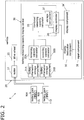
- the vehicle 20 is an electric motorcycle that travels when supplied with power from the two battery packs 10 installed under the seat 20a. As shown in FIG. 2 , the vehicle 20 has the motor 21, the rear wheel (drive wheel) 22, a front wheel 23 (see FIG. 1 ), and a battery remaining capacity display device 30.
- the motor 21 receives the power supplied from the battery packs 10 and transmits a rotational driving force to the axle of the rear wheel 22, which is the drive wheel.
- the front wheel 23 is a steered wheel provided between the front part of the vehicle 20 and the road surface, and the travel direction can be varied by changing the orientation in conjunction with the orientation of the handle bar 20b.
- the rear wheel 22 is a drive wheel provided between the road surface and the rear part of the vehicle 20 where the battery packs 10 are installed, and is rotationally driven by the motor 21.
- the battery remaining capacity display device 30 calculates and displays the remaining capacity of each battery pack 10.
- the battery remaining capacity display device 30 comprises a plurality of battery information storage components 31, a plurality of remaining capacity calculators 32, a combined remaining capacity calculator 33, a display component 34, a display controller 35, a display instruction component 36, a storage component 37, and an input component 38.
- a battery information storage component 31 is provided for each battery pack 10, and stores information such as the current supplied from the battery packs 10, and sums thereof.
- the battery remaining capacity display device 30 is provided with two battery information storage components 31. When distinguishing among the two battery information storage sections 31 in this description, they are indicated by 31A and 31B.
- the battery information storage component 31A stores information from the battery pack 10A
- the battery information storage component 31B stores information from the battery pack 10B.
- a remaining capacity calculator 32 is provided for each battery information storage component 31, and calculates the remaining capacity of the battery pack 10 on the basis of the information stored in the battery information storage component 31. Since the battery remaining capacity display device 30 in this embodiment is equipped with two battery information storage sections 31, two remaining capacity calculators 32 are provided. When distinguishing among the two remaining capacity calculators 32 in this description, they are indicated as 32A and 32B.
- the remaining capacity calculator 32A estimates the remaining capacity of the battery pack 10A on the basis of the information in the battery information storage component 31A.
- the remaining capacity calculator 32B estimates the remaining capacity of the battery pack 10B on the basis of the information in the battery information storage component 31B.
- the combined remaining capacity calculator 33 calculates the combined remaining capacity ratio of the plurality of battery packs 10 by combining the remaining capacities of the battery packs 10 calculated by the respective remaining capacity calculators 32.
- the following is used as the calculation formula.
- This calculation formula can be used to calculate the combined remaining capacity ratio when n-number of battery packs 10 are installed. For example, if we let the full charge capacity of the battery packs 10A and 10B be 1.0 kwh, the current remaining capacity of the battery pack 10A be 0.3 kwh, and the remaining capacity of the battery pack 10B be 0.7 kwh, the remaining capacity ratio to the full charge capacity of the battery pack 10A is 0.3 (30%), and the remaining capacity ratio to the full charge capacity of the battery pack 10B is 0.7 (70%). The remaining capacity ratios of the battery packs 10A and 10B are then added and divided by 2, and the quotient is multiplied by 100 to find the combined remaining capacity ratio of the battery packs 10A and 10B to be 50%.
- the display controller 35 controls the display component 34 to display the individual remaining capacities of the battery packs 10 calculated by the remaining capacity calculators 32, and the combined remaining capacity ratio calculated by the combined remaining capacity calculator 33.
- the storage component 37 stores the remaining capacity of each battery pack 10 calculated by the remaining capacity calculators 32, and the data for the combined remaining capacity calculated by the combined remaining capacity calculator 33.
- the display instruction component 36 instructs the display controller 35 to display or not to display the individual remaining capacity ratio, and to display or not to display the combined remaining capacity ratio.
- the display instruction component 36 gives an instruction for when the individual remaining capacity ratio and the combined remaining capacity ratio are displayed (see the dual display 350 shown in FIG. 3 (discussed below)), or when only the combined remaining capacity ratio is displayed (see the combined remaining capacity display 343 shown in FIG. 4 (discussed below)), or when only the individual remaining capacity ratio is displayed (see the individual remaining capacity display 344 shown in FIG. 5 (discussed below)).
- the input component 38 accepts an operation by the user.
- the display instruction component 36 instructs the display controller 35 to display either the dual display 350, the combined remaining capacity display 343, or the individual remaining capacity display 344, on the basis of the operation to the input component 38 by the user.
- the input component 38 may be something like a switch, for example, or may be a touch panel or the like.
- the configuration may be such that each time a switch is pressed, the display is switched between the dual display 350, the combined remaining capacity display 343, and individual remaining capacity display 344, or a switch may be provided for displaying each of these.
- the display component 34 is controlled by the display controller 35, and displays the combined remaining capacity of the battery packs 10A and 10B found by the combined remaining capacity calculator 33 and/or the individual remaining capacity ratios (percentage display) of the battery packs 10A and 10B.
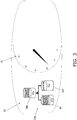
- FIG. 3 is a diagram showing an example of the display when the individual remaining capacity ratios and the combined remaining capacity ratio are displayed on the display component 34.
- the display component 34 is provided to the handle bar 20b, and is provided next to a speedometer 41 as shown in FIG. 3 .
- the dual display 350 that shows both the individual remaining capacity ratios and the combined remaining capacity ratio is given on the display component 34.
- the dual display 350 includes a combined remaining capacity display 340, a first remaining capacity display 341, and a second remaining capacity display 342.
- the first remaining capacity display 341 shows the remaining capacity ratio of the battery pack 10A, and the above-mentioned 30% is shown as an example here.
- the second remaining capacity display 342 shows the remaining capacity ratio of the battery pack 10B, and the above-mentioned 70% is shown as an example here.
- the combined remaining capacity display 340 shows the combined remaining capacity ratio found by combining the remaining capacity of the battery pack 10A with the remaining capacity of the battery pack 10B.
- the combined remaining capacity display 340 shows the above-mentioned 50% as an example.
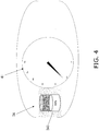
- FIG. 4 is a diagram showing an example of the display when the combined remaining capacity ratio is displayed on the display component 34, but the individual remaining capacity ratios are not displayed. As shown in FIG. 4 , the combined remaining capacity display 343 of the battery pack 10A and the battery pack 10B is given on the display component 34.
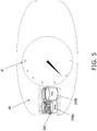
- FIG. 5 is a diagram showing an example of the display when the individual remaining capacity ratios are displayed on the display component 34, but the combined remaining capacity ratio is not displayed.
- the individual remaining capacity display 344 for the battery pack 10A and the battery pack 10B is given on the display component 34.
- the individual remaining capacity display 344 shows the remaining capacity of the battery pack 10A in the first remaining capacity display 344a, and the remaining capacity of the battery pack 10B in the second remaining capacity display 344b.
- FIG. 4 is a flowchart of the battery remaining capacity display method.
- step S 11 electrical current data from the BMU 11A of the battery pack 10A is stored in the battery information storage component 31A, and electrical current data from the BMU 11B of the battery pack 10B is stored in the battery information storage component 31B.
- step S12 the remaining capacity calculator 32A adds up the current on the basis of the current data stored in the battery information storing component 31A, and the remaining capacity calculator 32B adds up the current on the basis of the current data stored in the battery information storing component 31B.
- the remaining capacity calculator 32A calculates the remaining capacity of the current battery pack 10A by subtracting the summed current amount from the capacity of the battery pack 10A. In the above example, the remaining capacity calculator 32A calculates the remaining capacity of the battery pack 10A to be 0.3 kwh. Also, the remaining capacity calculator 32B calculates the remaining capacity of the current battery pack 10B by subtracting the summed current amount from the capacity of the battery pack 10B. In the above example, the remaining capacity calculator 32B calculates the remaining capacity of the battery pack 10B to be 0.7 kwh.
- step S14 the remaining capacity calculator 32A calculates the ratio of the remaining capacity to the capacity of the battery pack 10A, and the remaining capacity calculator 32B calculates the ratio of the remaining capacity to the capacity of the battery pack 10B.
- the remaining capacity calculator 32A calculates the ratio to be 0.3 (0.3 kwh ⁇ 1.0 kwh), and the remaining capacity calculator 32B calculates the ratio to 0.7 kwh (0.7 kwh ⁇ 1.0 kwh).
- Steps S12 to S14 correspond to an example of the individual remaining capacity calculation step.
- step S15 it is determined whether or not an input has been made on the input component 38 so that the dual display 350 will be given.
- step S16 the combined remaining capacity calculator 33 calculates the combined remaining capacity for the battery pack 10A and the battery pack 10B.
- the ratio (0.3 (30%)) of the remaining capacity to the capacity of the battery pack 10A is added to the ratio (0.7 (70%)) of the remaining capacity to the capacity of the battery pack 10B, and this sum is divided by the number of battery packs 10 (2), which gives a combined remaining capacity ratio (0.5 (50%)).
- Step S16 corresponds to an example of the combined remaining capacity calculation step.
- step S17 the display controller 35 updates the data for the combined remaining capacity stored in the storage component 37, and the data for the remaining capacity of the battery pack 10A and the remaining capacity of the battery pack 10B stored in the storage component 37.
- step S18 the display controller 35 controls the display component 34 so that the display component 34 gives the dual display 350 (the combined remaining capacity display 340, the first remaining capacity display 341, and the second remaining capacity display 342) on the basis of the data updated in step S17 above.
- Step S18 corresponds to an example of a display step.
- step S19 it is determined whether or not an input to display the combined value has been made on the input component 38.
- step S20 the combined remaining capacity ratio of the battery packs 10A and 10B is calculated.
- step S20 just as in step S16, calculation is performed using Formula 1, and the combined remaining capacity ratio is calculated.
- Step S20 corresponds to an example of the combined remaining capacity calculation step.
- step S21 the display controller 35 updates the data for the combined remaining capacity stored in the storage component 37 with the data for the combined remaining capacity calculated by the combined remaining capacity calculator 33.
- step S22 the display controller 35 causes the display component 34 to display the combined remaining capacity display 343 (see FIG. 4 ) on the basis of the updated data for the combined remaining capacity ratio.
- Step S22 corresponds to an example of a display step.
- step S19 if no command to display a combined value on the input component 38 has been inputted (or, to put this another way, if a command to display the individual remaining capacity has been inputted), in step S23 the display controller 35 updates the data for the individual remaining capacities of the battery packs 10A and 10B stored in the storage component 37 on the basis of the data for the individual remaining capacities calculated by the remaining capacity calculators 32A and 32B.
- step S24 the display controller 35 causes the display component 34 to display the individual remaining capacity display 344 (see FIG. 5 ) on the basis of the updated data for the remaining capacity ratio.
- Step S24 corresponds to an example of a display step.
- steps S11 to S24 are repeated, and the dual display 350, the combined remaining capacity display 343, and the individual remaining capacity display 344 show the combined remaining battery capacity ratio and the individual remaining capacity ratios of the battery packs 10A and 10B at the current time.
- the power consumption element may be a drill or another such electric power tool, for example.
- the battery remaining capacity display device, battery system, and battery remaining capacity display method of the present invention have the effect of allowing the user to easily grasp how far can be traveled, and can be widely applied to vehicles driven by replaceable batteries.
Landscapes
- Engineering & Computer Science (AREA)
- Mechanical Engineering (AREA)
- Chemical & Material Sciences (AREA)
- Transportation (AREA)
- Combustion & Propulsion (AREA)
- Power Engineering (AREA)
- General Chemical & Material Sciences (AREA)
- Electrochemistry (AREA)
- Chemical Kinetics & Catalysis (AREA)
- Manufacturing & Machinery (AREA)
- Life Sciences & Earth Sciences (AREA)
- Sustainable Development (AREA)
- Sustainable Energy (AREA)
- Charge And Discharge Circuits For Batteries Or The Like (AREA)
- Electric Propulsion And Braking For Vehicles (AREA)
- Secondary Cells (AREA)
- Remote Monitoring And Control Of Power-Distribution Networks (AREA)
Abstract
Description
- The present invention relates to a battery remaining capacity display device, a battery system, and a battery remaining capacity display method.
- A vehicle equipped with a plurality of batteries that can be connected in parallel has been proposed in the past (see, for example, Patent Literature 1).
- The vehicle disclosed in Patent Literature 1 is configured so that a plurality of batteries can be disposed spaced apart in the width direction of the vehicle. The user removes or adds batteries according to the distance to be traveled.
- Meanwhile, recent years have seen systems constructed in which batteries installed in a vehicle such as an electric motorcycle or an electric bicycle are used and then exchanged at a station where charged batteries are available.
- Patent Literature 1:
JP-A 2010-4666 - However, the following problems may be encountered when the remaining capacity of a plurality of batteries that can be connected in parallel is displayed for the user as in Patent Literature 1.
- Specifically, when displaying the remaining capacity of the batteries, it is conceivable that the remaining capacity of each of the batteries will simply be displayed, but in this case it is difficult for the user to determine how far can be traveled from the current location at the current remaining capacity.
- It is an object of the present invention to provide a battery remaining capacity display device, a battery system, and a battery remaining capacity display method with which it is easy to grasp how far can be traveled.
- The battery remaining capacity display device pertaining to the first invention comprises an individual remaining capacity calculator, a total remaining capacity calculator, a display controller, a display instruction component, and a display component. The individual remaining capacity calculator calculates the individual remaining capacities of a plurality of batteries that can be removably connected in parallel to a power consumption element. The total remaining capacity calculator calculates the total remaining capacity for a plurality of batteries on the basis of the individual remaining capacities calculated by the individual remaining capacity calculator. The display controller controls the display of the individual remaining capacities and the display of the total remaining capacity. The display instruction component instructs the display controller either to display or not to display. The display component displays the individual remaining capacities and the total remaining capacity. The display controller controls so that the individual remaining capacities and/or the total remaining capacity is displayed on the display component according to an instruction from the display instruction component.
- Thus, the total remaining capacity is calculated from the individual remaining capacities of the plurality of batteries and this total remaining capacity is displayed, so that when the power consumption element is a moving body such as vehicle, for example, the user can easily tell how far can be traveled from the current location.
- Also, displaying the individual remaining capacities of the plurality of batteries makes it easy for the user to know when a battery needs to be replaced.
- Also, displaying a total for the battery unit as a percentage, for example, allows the user to check the percentage of the total remaining capacity versus the total charge, and to more intuitively grasp how far can be traveled.
- Also, the individual remaining capacities may be displayed along with the total remaining capacity, for example, in which case, when exchanging batteries at a station, the user can easily grasp which of the plurality of batteries has a low remaining capacity. In addition, since the total remaining capacity is also displayed, the user can also intuitively grasp the how far can be traveled from the current location.
- Also, the display can be switched between individual remaining capacities and total remaining capacity, for example.
- The battery remaining capacity display device pertaining to the second invention is the battery remaining capacity display device pertaining to the first invention, wherein the display instruction component instructs the display controller to display the total remaining capacity on the display component during drive of the power consumption element, and to display the individual remaining capacities on the display component during battery exchange.
- Consequently, when the power consumption element is a moving body such as vehicle, for example, the total of the remaining capacities can be displayed when the vehicle is traveling, and the individual remaining capacities can be displayed when the batteries are replaced at a station.
- Therefore, the user can easily tell which batteries to replace at the station, and can also intuitively grasp how far can be traveled.
- The battery remaining capacity display device pertaining to the third invention is the battery remaining capacity display device pertaining to the first invention, wherein the display instruction component instructs the display controller to switch the display of the individual remaining capacities and the display of the total remaining capacity on the basis of a user setting.
- This makes it possible to switch between individual remaining capacity display and the total remaining capacity display based on the user setting.
- The battery remaining capacity display device pertaining to the fourth invention is the battery remaining capacity display device pertaining to the first invention, further comprising an input component that accepts an operation from a user. The display instruction component instructs the display controller to switch the display of the individual remaining capacities and the display of the total remaining capacity on the basis of a user operation to the input component.
- This makes it possible to switch between individual remaining capacities display and total remaining capacity display by the user input (direct operation).
- The battery remaining capacity display device pertaining to the fifth invention is the battery remaining capacity display device pertaining to the first invention, wherein the power consumption element is an electric motorcycle, an electric bicycle, an electrically assisted bicycle, or an electric power tool.
- Here, examples of the power consumption element include moving bodies (vehicles) such as an electric motorcycle and an electric bicycle. The power consumption element also includes power tools such as a drill.
- This makes it possible to calculate the remaining capacity of each battery of the power consumption element in which a plurality of batteries are installed, and to display the total of these remaining capacities.
- The battery system pertaining to the sixth invention comprises a plurality of batteries, an individual remaining capacity calculator, a total remaining capacity calculator, a display controller, a display instruction component, and a display component. The plurality of batteries can be connected in parallel and can be removably installed in a power consumption element. The individual remaining capacity calculator calculates the individual remaining capacities of the plurality of batteries. The total remaining capacity calculator calculates the total remaining capacity of the plurality of batteries based on the individual remaining capacities calculated by the individual remaining capacity calculator. The display controller controls the display of the individual remaining capacities and the display of the total remaining capacity. The display instruction component instructs the display controller to display or not to display. The display component displays the individual remaining capacities and the total remaining capacity. The display controller controls so that the individual remaining capacities and/or the total remaining capacity is displayed on the display component according to an instruction from the display instruction component.
- This makes it possible to display the total remaining capacity, either along with the individual remaining capacities or separately from the individual remaining capacities, on the basis of the remaining capacity of each of the plurality of batteries.
- The battery remaining capacity display method pertaining to the seventh invention comprises an individual remaining capacity calculation step, a total remaining capacity calculation step, a display instruction step, a display control step, and a display step. The individual remaining capacity calculation step involves calculating the individual remaining capacities of a plurality of batteries that can be connected in parallel and can be removably installed in a power consumption element. The total remaining capacity calculation step involves calculating the total remaining capacity of the plurality of batteries on the basis of the individual remaining capacities calculated in the individual remaining capacity calculating step. The display instruction step involves instructing whether to display or not to display the individual remaining capacities and the total remaining capacity. The display control step involves controlling the display of the individual remaining capacities and the display of the total remaining capacity according to an instruction from the display instruction step. The display step involves displaying the individual remaining capacities and/or the total remaining capacity on the basis of control performed in the display control step.
- Thus, the total remaining capacity is calculated from the individual remaining capacities of the plurality of batteries, and this total remaining capacity is displayed, so when the power consumption element is a moving body such as a vehicle, for example, the user can easily tell how far can be traveled from the current location.
- Also, displaying the individual remaining capacities of the plurality of batteries makes it easier for the user to tell which batteries need to be replaced.
- Also, for example, the individual remaining capacities may be displayed along with the total remaining capacity, and when exchanging batteries at a station, the user can easily tell which of the plurality of batteries have a low remaining capacity. In addition, since the total remaining capacity is also displayed, the user can intuitively grasp how far can be traveled from the current location.
- Also, for example, the display can be switched between the individual remaining capacities and the total remaining capacity.
- The present invention provides a battery remaining capacity display device, a battery system, and a battery remaining capacity display method with which it is easy to grasp how far can be traveled.
-
-
FIG. 1 is a diagram of a battery system in Embodiment 1 of the present invention, and a station where battery packs are exchanged; -
FIG. 2 is a block diagram of the configuration of the battery system inFIG. 1 ; -
FIG. 3 is a diagram showing an example of dual display by the battery remaining capacity display device inFIG. 2 ; -
FIG. 4 is a diagram showing an example of a combined remaining capacity display by the battery remaining capacity display device inFIG. 2 ; -
FIG. 5 is a diagram showing an example of an individual remaining capacity display by the battery remaining capacity display device inFIG. 2 ; and -
FIG. 6 is a flowchart of the operation of the battery remaining capacity display device inFIG. 2 . - The battery system, a battery remaining capacity display device, and battery remaining capacity display method pertaining to an embodiment of the present invention will now be described through reference to the drawings.
- The battery system 1 according to the first embodiment of the present invention will be described.
- The battery system 1 in this embodiment is a system that supplies power to a
vehicle 20, and comprises battery packs 10 and thevehicle 20, as shown inFIG. 1 . - As shown in
FIG. 1 , two battery packs 10 are installed in the vehicle 20 (an electric motorcycle, etc.). - In the
vehicle 20, power is supplied from the two battery packs 10 installed in the space below aseat 20a, and the rear wheel (drive wheel) 22 is rotationally driven, so that the vehicle can travel. - The
vehicle 20 can make use of what is known as a battery swap, in which the battery packs 10 whose remaining capacity has been reduced by travel, natural discharge, or the like are replaced with charged battery packs 10 at aspecific station 100. As shown inFIG. 1 , thestation 100 hasreceptacles 100a into which a plurality of batteries packs 10 are inserted. The battery packs 10 are disposed in thesereceptacles 100a.Stations 100 are set up at a plurality of locations such as gasoline stations. - In order to supply power to the
vehicle 20, in this embodiment two of the battery packs 10 are installed in thevehicle 20 in a manner that allows them to be replaced. Here, when distinguishing among the two battery packs 10, they will be calledbattery packs - As shown in
FIG. 2 , thebattery pack 10A has a BMU (battery management unit) 11A. TheBMU 11A controls the voltage and current of thebattery pack 10A. Similarly, thebattery pack 10B has aBMU 11B, and theBMU 11B controls the voltage and current of thebattery pack 10B. - The battery packs 10A and 10B store or release electric power. The two
battery packs vehicle 20. Therefore, even if just one of the two battery packs 10 is installed in thevehicle 20, power can still be supplied to themotor 21, and thevehicle 20 can travel. - The
vehicle 20 is an electric motorcycle that travels when supplied with power from the two battery packs 10 installed under theseat 20a. As shown inFIG. 2 , thevehicle 20 has themotor 21, the rear wheel (drive wheel) 22, a front wheel 23 (seeFIG. 1 ), and a battery remainingcapacity display device 30. - The
motor 21 receives the power supplied from the battery packs 10 and transmits a rotational driving force to the axle of therear wheel 22, which is the drive wheel. - The
front wheel 23 is a steered wheel provided between the front part of thevehicle 20 and the road surface, and the travel direction can be varied by changing the orientation in conjunction with the orientation of thehandle bar 20b. - The
rear wheel 22 is a drive wheel provided between the road surface and the rear part of thevehicle 20 where the battery packs 10 are installed, and is rotationally driven by themotor 21. - The battery remaining
capacity display device 30 calculates and displays the remaining capacity of eachbattery pack 10. - The battery remaining
capacity display device 30 comprises a plurality of battery information storage components 31, a plurality of remaining capacity calculators 32, a combined remainingcapacity calculator 33, adisplay component 34, adisplay controller 35, adisplay instruction component 36, astorage component 37, and aninput component 38. - A battery information storage component 31 is provided for each
battery pack 10, and stores information such as the current supplied from the battery packs 10, and sums thereof. In this embodiment, since two battery packs 10 are installed in thevehicle 20, the battery remainingcapacity display device 30 is provided with two battery information storage components 31. When distinguishing among the two battery information storage sections 31 in this description, they are indicated by 31A and 31B. The batteryinformation storage component 31A stores information from thebattery pack 10A, and the batteryinformation storage component 31B stores information from thebattery pack 10B. - A remaining capacity calculator 32 is provided for each battery information storage component 31, and calculates the remaining capacity of the
battery pack 10 on the basis of the information stored in the battery information storage component 31. Since the battery remainingcapacity display device 30 in this embodiment is equipped with two battery information storage sections 31, two remaining capacity calculators 32 are provided. When distinguishing among the two remaining capacity calculators 32 in this description, they are indicated as 32A and 32B. The remainingcapacity calculator 32A estimates the remaining capacity of thebattery pack 10A on the basis of the information in the batteryinformation storage component 31A. The remainingcapacity calculator 32B estimates the remaining capacity of thebattery pack 10B on the basis of the information in the batteryinformation storage component 31B. - The combined remaining
capacity calculator 33 calculates the combined remaining capacity ratio of the plurality of battery packs 10 by combining the remaining capacities of the battery packs 10 calculated by the respective remaining capacity calculators 32. The following is used as the calculation formula.
- Cnow : current total remaining capacity of the plurality of batteries
- Call : total capacity of the plurality of batteries
- Cnown : current remainig capacity of the n-th battery
- Call : capacity of then-th battery
- This calculation formula can be used to calculate the combined remaining capacity ratio when n-number of battery packs 10 are installed. For example, if we let the full charge capacity of the battery packs 10A and 10B be 1.0 kwh, the current remaining capacity of the
battery pack 10A be 0.3 kwh, and the remaining capacity of thebattery pack 10B be 0.7 kwh, the remaining capacity ratio to the full charge capacity of thebattery pack 10A is 0.3 (30%), and the remaining capacity ratio to the full charge capacity of thebattery pack 10B is 0.7 (70%). The remaining capacity ratios of the battery packs 10A and 10B are then added and divided by 2, and the quotient is multiplied by 100 to find the combined remaining capacity ratio of the battery packs 10A and 10B to be 50%. - The
display controller 35 controls thedisplay component 34 to display the individual remaining capacities of the battery packs 10 calculated by the remaining capacity calculators 32, and the combined remaining capacity ratio calculated by the combined remainingcapacity calculator 33. - The
storage component 37 stores the remaining capacity of eachbattery pack 10 calculated by the remaining capacity calculators 32, and the data for the combined remaining capacity calculated by the combined remainingcapacity calculator 33. - The
display instruction component 36 instructs thedisplay controller 35 to display or not to display the individual remaining capacity ratio, and to display or not to display the combined remaining capacity ratio. - Specifically, the
display instruction component 36 gives an instruction for when the individual remaining capacity ratio and the combined remaining capacity ratio are displayed (see the dual display 350 shown inFIG. 3 (discussed below)), or when only the combined remaining capacity ratio is displayed (see the combined remainingcapacity display 343 shown inFIG. 4 (discussed below)), or when only the individual remaining capacity ratio is displayed (see the individual remainingcapacity display 344 shown inFIG. 5 (discussed below)). - The
input component 38 accepts an operation by the user. Thedisplay instruction component 36 instructs thedisplay controller 35 to display either the dual display 350, the combined remainingcapacity display 343, or the individual remainingcapacity display 344, on the basis of the operation to theinput component 38 by the user. Theinput component 38 may be something like a switch, for example, or may be a touch panel or the like. For example, the configuration may be such that each time a switch is pressed, the display is switched between the dual display 350, the combined remainingcapacity display 343, and individual remainingcapacity display 344, or a switch may be provided for displaying each of these. - The
display component 34 is controlled by thedisplay controller 35, and displays the combined remaining capacity of the battery packs 10A and 10B found by the combined remainingcapacity calculator 33 and/or the individual remaining capacity ratios (percentage display) of the battery packs 10A and 10B. -
FIG. 3 is a diagram showing an example of the display when the individual remaining capacity ratios and the combined remaining capacity ratio are displayed on thedisplay component 34. Thedisplay component 34 is provided to thehandle bar 20b, and is provided next to aspeedometer 41 as shown inFIG. 3 . The dual display 350 that shows both the individual remaining capacity ratios and the combined remaining capacity ratio is given on thedisplay component 34. The dual display 350 includes a combined remainingcapacity display 340, a first remainingcapacity display 341, and a second remainingcapacity display 342. The first remainingcapacity display 341 shows the remaining capacity ratio of thebattery pack 10A, and the above-mentioned 30% is shown as an example here. The second remainingcapacity display 342 shows the remaining capacity ratio of thebattery pack 10B, and the above-mentioned 70% is shown as an example here. - The combined remaining
capacity display 340 shows the combined remaining capacity ratio found by combining the remaining capacity of thebattery pack 10A with the remaining capacity of thebattery pack 10B. InFIG. 3 , the combined remainingcapacity display 340 shows the above-mentioned 50% as an example. -
FIG. 4 is a diagram showing an example of the display when the combined remaining capacity ratio is displayed on thedisplay component 34, but the individual remaining capacity ratios are not displayed. As shown inFIG. 4 , the combined remainingcapacity display 343 of thebattery pack 10A and thebattery pack 10B is given on thedisplay component 34. -
FIG. 5 is a diagram showing an example of the display when the individual remaining capacity ratios are displayed on thedisplay component 34, but the combined remaining capacity ratio is not displayed. As shown inFIG. 5 , the individual remainingcapacity display 344 for thebattery pack 10A and thebattery pack 10B is given on thedisplay component 34. The individual remainingcapacity display 344 shows the remaining capacity of thebattery pack 10A in the first remainingcapacity display 344a, and the remaining capacity of thebattery pack 10B in the second remainingcapacity display 344b. - Next, the operation of the battery system 1 in this embodiment will be described, and an example of the battery remaining capacity display method of the present invention will also be discussed at the same time.
FIG. 4 is a flowchart of the battery remaining capacity display method. - As shown in
FIG. 4 , in step S 11, electrical current data from theBMU 11A of thebattery pack 10A is stored in the batteryinformation storage component 31A, and electrical current data from theBMU 11B of thebattery pack 10B is stored in the batteryinformation storage component 31B. - Next, in step S12, the remaining
capacity calculator 32A adds up the current on the basis of the current data stored in the batteryinformation storing component 31A, and the remainingcapacity calculator 32B adds up the current on the basis of the current data stored in the batteryinformation storing component 31B. - Next, in step S13, the remaining
capacity calculator 32A calculates the remaining capacity of thecurrent battery pack 10A by subtracting the summed current amount from the capacity of thebattery pack 10A. In the above example, the remainingcapacity calculator 32A calculates the remaining capacity of thebattery pack 10A to be 0.3 kwh. Also, the remainingcapacity calculator 32B calculates the remaining capacity of thecurrent battery pack 10B by subtracting the summed current amount from the capacity of thebattery pack 10B. In the above example, the remainingcapacity calculator 32B calculates the remaining capacity of thebattery pack 10B to be 0.7 kwh. - Next, in step S14, the remaining
capacity calculator 32A calculates the ratio of the remaining capacity to the capacity of thebattery pack 10A, and the remainingcapacity calculator 32B calculates the ratio of the remaining capacity to the capacity of thebattery pack 10B. In the above example, the remainingcapacity calculator 32A calculates the ratio to be 0.3 (0.3 kwh ÷ 1.0 kwh), and the remainingcapacity calculator 32B calculates the ratio to 0.7 kwh (0.7 kwh ÷ 1.0 kwh). Steps S12 to S14 correspond to an example of the individual remaining capacity calculation step. - Next, in step S15, it is determined whether or not an input has been made on the
input component 38 so that the dual display 350 will be given. - Here, if the user has made an input indicating that the dual display 350 is to be given, in step S16 the combined remaining
capacity calculator 33 calculates the combined remaining capacity for thebattery pack 10A and thebattery pack 10B. In the above example, using Formula 1, the ratio (0.3 (30%)) of the remaining capacity to the capacity of thebattery pack 10A is added to the ratio (0.7 (70%)) of the remaining capacity to the capacity of thebattery pack 10B, and this sum is divided by the number of battery packs 10 (2), which gives a combined remaining capacity ratio (0.5 (50%)). Step S16 corresponds to an example of the combined remaining capacity calculation step. - Next, in step S17, the
display controller 35 updates the data for the combined remaining capacity stored in thestorage component 37, and the data for the remaining capacity of thebattery pack 10A and the remaining capacity of thebattery pack 10B stored in thestorage component 37. - Next, in step S18, the
display controller 35 controls thedisplay component 34 so that thedisplay component 34 gives the dual display 350 (the combined remainingcapacity display 340, the first remainingcapacity display 341, and the second remaining capacity display 342) on the basis of the data updated in step S17 above. Step S18 corresponds to an example of a display step. - On the other hand, if no input has been made to give the dual display 350 in step S15, in step S19 it is determined whether or not an input to display the combined value has been made on the
input component 38. - Here, if the user has inputted a command to display a combined value, in step S20 the combined remaining capacity ratio of the battery packs 10A and 10B is calculated. In step S20, just as in step S16, calculation is performed using Formula 1, and the combined remaining capacity ratio is calculated. Step S20 corresponds to an example of the combined remaining capacity calculation step.
- Next, in step S21, the
display controller 35 updates the data for the combined remaining capacity stored in thestorage component 37 with the data for the combined remaining capacity calculated by the combined remainingcapacity calculator 33. Then, in step S22, thedisplay controller 35 causes thedisplay component 34 to display the combined remaining capacity display 343 (seeFIG. 4 ) on the basis of the updated data for the combined remaining capacity ratio. Step S22 corresponds to an example of a display step. - On the other hand, in step S19, if no command to display a combined value on the
input component 38 has been inputted (or, to put this another way, if a command to display the individual remaining capacity has been inputted), in step S23 thedisplay controller 35 updates the data for the individual remaining capacities of the battery packs 10A and 10B stored in thestorage component 37 on the basis of the data for the individual remaining capacities calculated by the remainingcapacity calculators - Next, in step S24, the
display controller 35 causes thedisplay component 34 to display the individual remaining capacity display 344 (seeFIG. 5 ) on the basis of the updated data for the remaining capacity ratio. Step S24 corresponds to an example of a display step. - With the power to the
vehicle 20 on, steps S11 to S24 are repeated, and the dual display 350, the combined remainingcapacity display 343, and the individual remainingcapacity display 344 show the combined remaining battery capacity ratio and the individual remaining capacity ratios of the battery packs 10A and 10B at the current time. - When the power to the
vehicle 20 is switched off, display control of the battery remaining capacity ends. -
- (3-1) The battery remaining
capacity display device 30 in this embodiment comprises the remainingcapacity calculators capacity calculator 33, thedisplay controller 35, thedisplay instruction component 36, and thedisplay component 34. The remainingcapacity calculators vehicle 20. The combined remainingcapacity calculator 33 calculates the combined remaining capacity ratio of the battery packs 10A and 10B on the basis of the individual remaining capacities calculated by the remainingcapacity calculators display controller 35 controls the display of the individual remaining capacities and the display of the total remaining capacity. Thedisplay instruction component 36 instructs thedisplay controller 35 to display or not to display. Thedisplay component 34 displays the individual remaining capacities and the combined remaining capacity (an example of the total remaining capacity). Thedisplay controller 35 controls thedisplay component 34 to display the individual remaining capacities and/or the combined remaining capacity according to an instruction from thedisplay instruction component 36.
Thus, the individual remaining capacities of the battery packs 10A and 10B are acquired, the combined remaining capacity ratio is calculated, and the combined remaining capacity ratio is displayed, which makes it easy for the user to determine how far can be traveled from the current location.
Also, displaying the individual remaining capacities of the battery packs 10A and 10B allows the user to easily tell which of the battery packs 10A and 10B needs to be replaced.
Also, for example, displaying the total of the battery packs 10A and 10B as a percentage makes it possible to confirm percentage of the total remaining capacity with respect to the total amount, and how far can be traveled can be determined more intuitively.
Also, for example, since the individual remaining capacity ratios can be displayed along with the combined remaining capacity ratio, as shown in the dual display 350, when replacing the battery packs 10 at thestation 100, the user can easily tell which of the plurality of battery packs 10 have a low remaining capacity. Also, since the combined remaining capacity ratio is also displayed, the user can intuitively grasp how far can be traveled from the current location.
Also, for example, the display can be switched between the individual remaining capacities and the combined remaining capacity. - (3-2) The battery remaining
capacity display device 30 in this embodiment further comprises theinput component 38 that accepts an operation from the user. Thedisplay instruction component 36 instructs thedisplay controller 35 to switch between a display of the individual remaining capacities and a display of the combined remaining capacity on the basis of user operation of theinput component 38.
This makes it possible to switch between an individual remaining capacity display and a combined remaining capacity display on the basis of the user setting.
Also, while the vehicle is traveling, the combined remaining capacity ratio can be displayed, and the individual remaining capacity ratios can be displayed when the battery packs 10 are being replaced at thestation 100.
Therefore, the user can easily tell which battery packs 10 to exchange at thestation 100, and can also intuitively grasp how far can be traveled. - (3-3) With the battery remaining
capacity display device 30 in this embodiment, thevehicle 20 is an electric motorcycle or an electric bicycle.
Here, thevehicle 20 is a vehicle including electric motorcycles and electric bicycles.
Consequently, the remaining capacity of eachbattery pack 10 in thevehicle 20 in which the battery packs 10A and 10B are installed can be calculated, and the combined remaining capacity can be displayed. - (3-4) The battery system 1 in this embodiment comprises the plurality of battery packs 10, the remaining
capacity calculators capacity calculator 33, thedisplay controller 35, thedisplay instruction component 36, and thedisplay component 34. The battery packs 10 can be removably connected in parallel in thevehicle 20. The remainingcapacity calculators vehicle 20. The combined remainingcapacity calculator 33 calculates the combined remaining capacity ratio of the battery packs 10A and 10B on the basis of the individual remaining capacities calculated by the remainingcapacity calculators display controller 35 controls the display of the individual remaining capacities and the display of the total remaining capacity. Thedisplay instruction component 36 instructs thedisplay controller 35 to display or not to display. Thedisplay component 34 displays the individual remaining capacities and the total remaining capacity. Thedisplay controller 35 controls thedisplay component 34 to display individual remaining capacities and/or the total remaining capacity according to an instruction from thedisplay instruction component 36.
Consequently, the battery system 1 can acquire the remaining capacity for each of the battery packs 10A and 10B, and display the combined remaining capacity ratio. - (3-5) The remaining battery capacity display method in Embodiment 1 comprises steps S12 to S14 (an example of an individual remaining capacity calculation step), steps S16 and S20 (an example of a total remaining capacity calculation step), steps S15 and S19 (an example of a display instruction step), steps S18, S22, and S24 (an example of a display control step and a display step). Steps S12 to S14 involve calculating the remaining capacity for each of the battery packs 10A and 10B that can be removably connected in parallel in the
vehicle 20. Steps S16 and S20 involve calculating the combined remaining capacity ratio for the battery packs 10A and 10B on the basis of the individual remaining capacities of the battery packs 10A and 10B calculated in steps S12 to S14. Steps S15 and S19 involve giving an instruction to display or not to display the individual remaining capacities and the total remaining capacity. Steps S18, S22, and S24 involve controlling the display of the individual remaining capacities and the display of the total remaining capacity according to the instruction from steps S15 and S19, and displaying the individual remaining capacities and/or the total remaining capacity based on this control.
Thus calculating the total remaining capacity from the individual remaining capacities of the battery packs 10A and 10B, and displaying this total remaining capacity makes it easy for the user to tell how far can be traveled from the current location. Also, displaying the individual remaining capacities of the plurality of battery packs 10 allows the user to easily grasp which battery packs 10 need to be exchanged. - An embodiment of the present invention was described above, but the present invention is not limited to or by the above embodiment, and various modifications are possible without departing from the gist of the invention.
- (A) In the above embodiment, the display on the
display component 34 was switched between the dual display 350, the combined remainingcapacity display 343, and the individual remainingcapacity display 344, but the dual display 350 may not be displayed, and the display on thedisplay component 34 may be switched between just the combined remainingcapacity display 343 and the individual remainingcapacity display 344 with theinput component 38. - (B) In the above embodiment, the remaining capacities of the battery packs 10A and 10B were displayed as a percentage, but this is not the only option. The present remaining capacity values (in the example in
FIG. 3 , 0.3kwh and 0.7kwh) may be displayed, or the full charge capacity may be displayed along with the present remaining capacity values. Also, as the total remaining capacity, the combined remaining capacity was displayed as a ratio by looking at the plurality of battery packs 10 as asingle battery pack 10, but the total of the remaining capacity values (in the example inFIG. 3 , 1.0 kwh) may be displayed, or the total of the full charge capacities of the battery packs 10A and 10B (in the example inFIG. 3 , 2.0 kwh) may be displayed along with the present total of the remaining capacity values.
In short, what is important is that the user can check the total remaining capacities of the plurality of battery packs 10, and that the user can check the remaining capacity of each of the plurality of battery packs 10. - (C) In the above embodiment, the battery remaining
capacity display device 30 calculated the remaining capacities of the battery packs 10A and 10B, but these remaining capacities may be calculated in the battery packs 10A and 10B and sent to the battery remainingcapacity display device 30. That is, a capacitor (corresponds to an example of a battery) and an individual remaining capacity calculator that calculates the remaining capacity of the capacitor may be provided to each of the battery packs 10A and 10B. In this case, the remaining batterycapacity display device 30 need not be provided with the batteryinformation storage components capacity calculators - (D) In the above embodiment, the
display instruction component 36 switched thedisplay component 34 between the combined remainingcapacity display 343 and the individual remainingcapacity display 344 on the basis of user input to theinput component 38, but, for example, thedisplay instruction component 36 may be incorporated into a navigation system or the like, and control may be performed so that the combined remainingcapacity display 343 is given while the vehicle is traveling, and the individual remainingcapacity display 344 is given when the vehicle is close to arriving at thestation 100. - (E) In the above embodiment, two battery packs 10 were provided, but the number is not limited to two, and three or more battery packs 10 may be provided. In this case, the number of displays of the individual remaining capacity shown in
FIGS. 3 and 7 increases according to the number of battery packs 10. - (F) In the above embodiment, an electric motorcycle was described as the power consumption element, for example, but it may be an electric bicycle, an electrically assisted bicycle, an electric unicycle, an electric automobile (EV), a PHV (plug-in hybrid vehicle), or some other such vehicle.
- Furthermore, the power consumption element may be a drill or another such electric power tool, for example.
- The battery remaining capacity display device, battery system, and battery remaining capacity display method of the present invention have the effect of allowing the user to easily grasp how far can be traveled, and can be widely applied to vehicles driven by replaceable batteries.
-
- 1: battery system
- 10, 10A, 10B: battery pack (an example of a battery)
- 11A, 11B: BMU
- 20: vehicle (an example of a power consumption element)
- 20a: seat
- 20b: handle bar
- 21: motor
- 22: rear wheel
- 23: front wheel
- 30: remaining battery capacity display device
- 31, 31A, 31B: battery information storage component
- 32, 32A, 32B: remaining capacity calculator (an example of an individual remaining capacity calculator)
- 33: combined remaining capacity calculator (an example of a total remaining capacity calculator)
- 34: display component
- 35: display controller
- 36: display instruction component
- 37: storage component
- 38: input component
- 41: speedometer
- 100: station
- 100a: receptacle
- 340: combined remaining capacity display
- 341: first remaining capacity display
- 342: second remaining capacity display
- 343: combined remaining capacity display
- 344: individual remaining capacity display
- 344a: first remaining capacity display
- 344b: second remaining capacity display
- 350: dual display
Claims (7)
- A battery remaining capacity display device, comprising:an individual remaining capacity calculator configured to calculate individual remaining capacities of a plurality of batteries configured to be removably connected in parallel to a power consumption element;a total remaining capacity calculator configured to calculate total remaining capacity of the plurality of batteries on the basis of the individual remaining capacities calculated by the individual remaining capacity calculator;a display controller configured to control display of the individual remaining capacities and display of the total remaining capacity;a display instruction component configured to instruct the display controller either to display or not to display; anda display component configure to display the individual remaining capacities and the total remaining capacity,wherein the display controller controls so that the individual remaining capacities and/or the total remaining capacity is displayed on the display component according to an instruction from the display instruction component.
- The battery remaining capacity display device according to Claim 1,
wherein the display instruction component instructs the display controller to display the total remaining capacity on the display component during drive of the power consumption element, and to display the individual remaining capacities on the display component during battery exchange. - The battery remaining capacity display device according to Claim 1,
wherein the display instruction component instructs the display controller to switch the display of the individual remaining capacities and the display of the total remaining capacity on the basis of a user setting. - The battery remaining capacity display device according to Claim 1,
further comprising an input component configured to accept an operation from a user,
wherein the display instruction component instructs to switch the display of the individual remaining capacities and the display of the total remaining capacity on the basis of a user operation to the input component. - The battery remaining capacity display device according to Claim 1,
wherein the power consumption element is an electric motorcycle, an electric bicycle, an electrically assisted bicycle, or an electric power tool. - A battery system, comprising:a plurality of batteries configured to be removably connected in parallel to a power consumption element;an individual remaining capacity calculator configured to calculate individual remaining capacities of the plurality of batteries;a total remaining capacity calculator configured to calculate total remaining capacity of the plurality of batteries on the basis of the individual remaining capacities calculated by the individual remaining capacity calculator;a display controller configured to control display of the individual remaining capacities and display of the total remaining capacity;a display instruction component configured to instruct the display controller either to display or not to display; anda display component configured to display the individual remaining capacities and the total remaining capacity,wherein the display controller controls so that the individual remaining capacities and/or the total remaining capacity is displayed on the display component according to an instruction from the display instruction component.
- A remaining battery capacity display method, comprising:an individual remaining capacity calculation step of calculating individual remaining capacities of a plurality of batteries configured to be removably connected in parallel to a power consumption element;a total remaining capacity calculation step of calculating total remaining capacity of the plurality of batteries on the basis of the individual remaining capacities calculated in the individual remaining capacity calculating step;a display instruction step of instructing whether to display or not display the individual remaining capacities and the total remaining capacity;a display control step of controlling display of the individual remaining capacities and display of the total remaining capacity according to an instruction from the display instruction step; anda display step of displaying the individual remaining capacities and/or the total remaining capacity on the basis of control performed in the display control step.
Applications Claiming Priority (2)
| Application Number | Priority Date | Filing Date | Title |
|---|---|---|---|
| JP2015224348A JP6707843B2 (en) | 2015-11-17 | 2015-11-17 | Battery residual quantity display device, battery system and battery residual quantity display method |
| PCT/JP2016/082622 WO2017086168A1 (en) | 2015-11-17 | 2016-11-02 | Remaining battery capacity display device, battery system and remaining battery capacity display method |
Publications (3)
| Publication Number | Publication Date |
|---|---|
| EP3379684A1 true EP3379684A1 (en) | 2018-09-26 |
| EP3379684A4 EP3379684A4 (en) | 2019-01-02 |
| EP3379684B1 EP3379684B1 (en) | 2021-03-17 |
Family
ID=58718789
Family Applications (1)
| Application Number | Title | Priority Date | Filing Date |
|---|---|---|---|
| EP16866170.0A Active EP3379684B1 (en) | 2015-11-17 | 2016-11-02 | Remaining battery capacity display device, battery system and remaining battery capacity display method |
Country Status (7)
| Country | Link |
|---|---|
| US (1) | US10518640B2 (en) |
| EP (1) | EP3379684B1 (en) |
| JP (1) | JP6707843B2 (en) |
| MY (1) | MY195711A (en) |
| PH (1) | PH12018500462A1 (en) |
| TW (1) | TWI635000B (en) |
| WO (1) | WO2017086168A1 (en) |
Cited By (1)
| Publication number | Priority date | Publication date | Assignee | Title |
|---|---|---|---|---|
| CN111376790A (en) * | 2018-12-28 | 2020-07-07 | 观致汽车有限公司 | Method, apparatus, device and medium for determining a mileage of a vehicle |
Families Citing this family (14)
| Publication number | Priority date | Publication date | Assignee | Title |
|---|---|---|---|---|
| JP6707843B2 (en) * | 2015-11-17 | 2020-06-10 | オムロン株式会社 | Battery residual quantity display device, battery system and battery residual quantity display method |
| JP6623725B2 (en) | 2015-12-01 | 2019-12-25 | オムロン株式会社 | Battery remaining amount estimation system and battery remaining amount estimation method |
| KR102154385B1 (en) * | 2017-05-31 | 2020-09-09 | 주식회사 엘지화학 | System and method for remotely managing vehicle battery |
| CN107599844B (en) * | 2017-09-07 | 2020-05-08 | 深圳埃瑞斯瓦特新能源有限公司 | Remaining mileage detection method for electric automobile |
| EP3503313B1 (en) * | 2017-12-20 | 2022-02-09 | Amprio GmbH | Multi-battery adapter for establishing an electrical connection between at least two traction batteries on the one hand and a drive unit of an electrical bicycle on the other |
| JPWO2019240245A1 (en) * | 2018-06-14 | 2021-07-15 | 本田技研工業株式会社 | Display device and display method |
| EP3826131A4 (en) * | 2018-07-20 | 2022-04-06 | Audio-Technica Corporation | WIRELESS EARPHONE CHARGER, WIRELESS EARPHONES, AND WIRELESS EARPHONE SYSTEM |
| JP2020065422A (en) * | 2018-10-19 | 2020-04-23 | トヨタ自動車株式会社 | Display device and vehicle including the same |
| JP7131290B2 (en) * | 2018-10-19 | 2022-09-06 | トヨタ自動車株式会社 | DISPLAY DEVICE AND VEHICLE INCLUDING THE SAME |
| JP7160004B2 (en) * | 2019-08-30 | 2022-10-25 | トヨタ自動車株式会社 | Display system, vehicle, and secondary battery status display method |
| US12358398B2 (en) | 2019-12-18 | 2025-07-15 | Honda Motor Co., Ltd. | Electric power device, display device, charging rate calculation method, and memory medium |
| CN117120860A (en) * | 2021-04-15 | 2023-11-24 | 三星电子株式会社 | Method and device for managing multiple batteries |
| JP7639643B2 (en) * | 2021-09-30 | 2025-03-05 | トヨタ自動車株式会社 | Vehicle, notification system, method and program |
| TWI854400B (en) * | 2022-12-19 | 2024-09-01 | 亞福儲能股份有限公司 | Hybrid power system and optimizing method thereof |
Family Cites Families (57)
| Publication number | Priority date | Publication date | Assignee | Title |
|---|---|---|---|---|
| JP3235167B2 (en) * | 1992-02-06 | 2001-12-04 | 株式会社タツノ・メカトロニクス | Electric car |
| JP3400034B2 (en) * | 1993-10-12 | 2003-04-28 | 本田技研工業株式会社 | Battery remaining capacity remote display for electric vehicles |
| US5549984A (en) * | 1994-07-25 | 1996-08-27 | Globe-Union Inc. | Control and indicator circuit for a dual battery system |
| JPH11102732A (en) * | 1997-09-26 | 1999-04-13 | Suzuki Motor Corp | Battery power measurement device for mobile power |
| JP2002304136A (en) * | 2001-01-17 | 2002-10-18 | Seiko Epson Corp | Electronic equipment provided with an organic electroluminescence display device |
| JP2003256084A (en) * | 2002-03-06 | 2003-09-10 | Fujitsu Ltd | Battery monitoring system |
| US6650089B1 (en) | 2002-10-16 | 2003-11-18 | Texas Instruments Incorporated | Control circuit for multiple battery systems with capacity gauge on end equipment |
| JP4161854B2 (en) * | 2003-09-02 | 2008-10-08 | ソニー株式会社 | Battery remaining capacity calculation method, battery remaining capacity calculation device, and battery remaining capacity calculation program |
| JP4275078B2 (en) | 2005-01-13 | 2009-06-10 | 三洋電機株式会社 | Battery current limit control method |
| JP2009038612A (en) * | 2007-08-02 | 2009-02-19 | Nikon Corp | Cameras and electronic devices |
| US20090132186A1 (en) | 2007-11-15 | 2009-05-21 | Broadcom Corporation | Method and system for reporting battery status based on current estimation |
| JP4277928B1 (en) * | 2007-12-07 | 2009-06-10 | トヨタ自動車株式会社 | vehicle |
| JP2009151953A (en) * | 2007-12-18 | 2009-07-09 | Mitsumi Electric Co Ltd | Battery pack and electronic equipment |
| JP4893653B2 (en) | 2008-02-19 | 2012-03-07 | トヨタ自動車株式会社 | Vehicle, rechargeable battery state of charge estimation method and vehicle control method |
| EP2130707A3 (en) * | 2008-06-02 | 2010-11-10 | Apex Science Co. Ltd. | Individual-charge and merged-discharge battery set |
| JP4577413B2 (en) | 2008-06-20 | 2010-11-10 | トヨタ自動車株式会社 | vehicle |
| KR101180404B1 (en) * | 2008-09-22 | 2012-09-13 | 닛뽕빅터 가부시키가이샤 | Electronic device, method for displaying battery remaining power and method for displaying operable duration |
| JP2010237796A (en) * | 2009-03-30 | 2010-10-21 | Victor Co Of Japan Ltd | Electronic apparatus, and operable time display method |
| US8994334B2 (en) | 2009-06-03 | 2015-03-31 | Mitsubishi Heavy Industries, Ltd. | Battery state-of-charge calculation device |
| JP5488046B2 (en) | 2010-02-25 | 2014-05-14 | 株式会社デンソー | In-vehicle power supply |
| CN102340156A (en) | 2010-07-26 | 2012-02-01 | 联想(北京)有限公司 | Charging and discharging method for terminal and terminal |
| JP5653701B2 (en) * | 2010-09-28 | 2015-01-14 | 三菱電機株式会社 | Charge display device |
| JP5625727B2 (en) * | 2010-10-20 | 2014-11-19 | ソニー株式会社 | Battery pack, charging / discharging method thereof, and power consuming device |
| US9385552B2 (en) | 2010-10-25 | 2016-07-05 | Nokia Technologies Oy | Method of detecting charger type and estimating remaining recharging time for mobile devices with USB recharging |
| JP2012159357A (en) | 2011-01-31 | 2012-08-23 | Canon Inc | Battery device |
| CN103392133A (en) * | 2011-03-07 | 2013-11-13 | 株式会社日立制作所 | Battery state estimating method and battery management system |
| US9371067B2 (en) * | 2011-03-31 | 2016-06-21 | Elite Power Solutions Llc | Integrated battery control system |
| JP2013046512A (en) * | 2011-08-25 | 2013-03-04 | Makita Corp | Power supply device |
| WO2013027599A1 (en) * | 2011-08-25 | 2013-02-28 | 株式会社マキタ | Power supply apparatus |
| EP2761317A2 (en) | 2011-09-30 | 2014-08-06 | KPIT Technologies Limited | A system and method for determining state of charge of a battery |
| JP5801176B2 (en) * | 2011-12-19 | 2015-10-28 | 株式会社東芝 | Power storage device and maintenance method thereof |
| JP5887959B2 (en) * | 2012-01-27 | 2016-03-16 | トヨタ自動車株式会社 | Display device for hybrid vehicle |
| JP5919857B2 (en) | 2012-02-03 | 2016-05-18 | スズキ株式会社 | Charge / discharge control device |
| TW201341223A (en) * | 2012-04-09 | 2013-10-16 | Isuda Recreation & Sports Co Ltd | Electric vehicle with two charging batteries |
| US9285431B2 (en) | 2012-04-10 | 2016-03-15 | Tencent Technology (Shenzhen) Company Limited | Method for monitoring and managing battery charge level and apparatus for performing the same |
| JP2013225951A (en) | 2012-04-20 | 2013-10-31 | Panasonic Corp | Electric power sharing system, electronic apparatus, and method of sharing electric power |
| US9182451B2 (en) | 2012-07-30 | 2015-11-10 | Robert Bosch Gmbh | System and method for posteriori adaptation of a state of charge model in a battery |
| US20140095089A1 (en) | 2012-10-02 | 2014-04-03 | Zhijian James Wu | System and method for estimated battery state of charge |
| KR101547006B1 (en) | 2012-10-26 | 2015-08-24 | 주식회사 엘지화학 | Apparatus and method for estimating state of charging of battery |
| JP6013227B2 (en) * | 2013-02-22 | 2016-10-25 | 株式会社東芝 | Power storage device |
| US20140277887A1 (en) * | 2013-03-15 | 2014-09-18 | WM GreenTech Automotive Corp. | Method and system for detecting battery type and capacity and automatically adjusting related vehicle parameters |
| JP6054788B2 (en) | 2013-03-26 | 2016-12-27 | Necプラットフォームズ株式会社 | Storage battery residual quantity estimation device and residual quantity estimation method |
| KR20140139322A (en) | 2013-05-27 | 2014-12-05 | 삼성에스디아이 주식회사 | Battery management system and driving method thereof |
| JP2014233783A (en) * | 2013-05-31 | 2014-12-15 | 株式会社マキタ | Discharge control device, motor-driven appliance and attachment |
| CN104237791A (en) | 2013-06-20 | 2014-12-24 | 电子科技大学 | Lithium battery charge state estimation method, battery management system and battery system |
| WO2015045339A1 (en) * | 2013-09-27 | 2015-04-02 | パナソニックIpマネジメント株式会社 | Power distribution device and storage battery pack diagnosing method |
| US9131452B2 (en) | 2013-10-25 | 2015-09-08 | Motorola Solutions, Inc. | Method and apparatus for adjusting transmission power in a two-way device based on battery impedance |
| US9431837B2 (en) * | 2014-04-30 | 2016-08-30 | Johnson Controls Technology Company | Integrated battery management system and method |
| US9559536B2 (en) * | 2014-04-30 | 2017-01-31 | Johnson Controls Technology Company | State of charge indicator method and system |
| KR102225667B1 (en) | 2014-07-02 | 2021-03-12 | 삼성전자주식회사 | Method and apparatus for estimating state of battery |
| CA2908541A1 (en) * | 2014-12-18 | 2016-06-18 | Instavolt Inc. | System and method for battery charging |
| US10297877B2 (en) * | 2015-03-16 | 2019-05-21 | Kabushiki Kaisha Toshiba | Storage battery control device and storage battery control method |
| US10040370B2 (en) * | 2015-09-19 | 2018-08-07 | Ningbo Wise Digital Technology Co., Ltd | Container comprising a battery, transportation system comprising the same and method thereof |
| US10322634B2 (en) * | 2015-10-14 | 2019-06-18 | Ford Global Technologies, Llc | Estimating battery capacity in an electric vehicle |
| US20170136914A1 (en) * | 2015-11-17 | 2017-05-18 | Johnson Controls Technology Company | Systems and methods for visualizing battery data |
| JP6707843B2 (en) * | 2015-11-17 | 2020-06-10 | オムロン株式会社 | Battery residual quantity display device, battery system and battery residual quantity display method |
| JP6623725B2 (en) | 2015-12-01 | 2019-12-25 | オムロン株式会社 | Battery remaining amount estimation system and battery remaining amount estimation method |
-
2015
- 2015-11-17 JP JP2015224348A patent/JP6707843B2/en active Active
-
2016
- 2016-11-02 US US15/758,748 patent/US10518640B2/en active Active
- 2016-11-02 WO PCT/JP2016/082622 patent/WO2017086168A1/en not_active Ceased
- 2016-11-02 EP EP16866170.0A patent/EP3379684B1/en active Active
- 2016-11-02 MY MYPI2018700834A patent/MY195711A/en unknown
- 2016-11-11 TW TW105136815A patent/TWI635000B/en active
-
2018
- 2018-03-02 PH PH12018500462A patent/PH12018500462A1/en unknown
Cited By (1)
| Publication number | Priority date | Publication date | Assignee | Title |
|---|---|---|---|---|
| CN111376790A (en) * | 2018-12-28 | 2020-07-07 | 观致汽车有限公司 | Method, apparatus, device and medium for determining a mileage of a vehicle |
Also Published As
| Publication number | Publication date |
|---|---|
| US20190039474A1 (en) | 2019-02-07 |
| TW201718288A (en) | 2017-06-01 |
| EP3379684B1 (en) | 2021-03-17 |
| WO2017086168A1 (en) | 2017-05-26 |
| JP2017093250A (en) | 2017-05-25 |
| US10518640B2 (en) | 2019-12-31 |
| EP3379684A4 (en) | 2019-01-02 |
| JP6707843B2 (en) | 2020-06-10 |
| MY195711A (en) | 2023-02-07 |
| PH12018500462A1 (en) | 2018-09-10 |
| TWI635000B (en) | 2018-09-11 |
Similar Documents
| Publication | Publication Date | Title |
|---|---|---|
| EP3379684B1 (en) | Remaining battery capacity display device, battery system and remaining battery capacity display method | |
| US10661676B2 (en) | Guide device, guide system, and guide method | |
| EP3379682A1 (en) | Charge/discharge control device, charge/discharge control system, and charge/discharge control method | |
| US11010824B2 (en) | Battery reservation device and battery reservation method | |
| US10643272B2 (en) | Battery reservation device | |
| US10600116B2 (en) | Reservation management device, reservation management system, and reservation management method | |
| EP3379467A1 (en) | Battery reservation device and battery reservation method | |
| US10600262B2 (en) | Display device for electric vehicle | |
| US9213670B2 (en) | Method and user interface system of a vehicle for providing an energy level gauge relative to a vehicle range meter | |
| US9574889B2 (en) | Apparatus and method for providing distance to empty of green vehicle | |
| DE102012223315B4 (en) | Climate control advisory system and vehicle | |
| US10919410B2 (en) | Charge/discharge control device, charge/discharge control system, and remaining battery capacity adjustment method | |
| EP3184412A1 (en) | Battery bracket to be used in power assist moving body, battery unit, power assist unit, and power assist moving body | |
| US20150100226A1 (en) | Efficiency Gauge For Plug-In Electric Vehicle | |
| JP6516091B2 (en) | Charge amount display device of electric vehicle | |
| JP2020072581A (en) | Movable distance calculator | |
| CN115402140A (en) | System and method for bidirectional charging between electric vehicle and electric recreational vehicle | |
| US20180304764A1 (en) | Battery pack, and battery system comprising the same | |
| JP2021040370A (en) | Display device |
Legal Events
| Date | Code | Title | Description |
|---|---|---|---|
| STAA | Information on the status of an ep patent application or granted ep patent |
Free format text: STATUS: THE INTERNATIONAL PUBLICATION HAS BEEN MADE |
|
| PUAI | Public reference made under article 153(3) epc to a published international application that has entered the european phase |
Free format text: ORIGINAL CODE: 0009012 |
|
| STAA | Information on the status of an ep patent application or granted ep patent |
Free format text: STATUS: REQUEST FOR EXAMINATION WAS MADE |
|
| 17P | Request for examination filed |
Effective date: 20180228 |
|
| AK | Designated contracting states |
Kind code of ref document: A1 Designated state(s): AL AT BE BG CH CY CZ DE DK EE ES FI FR GB GR HR HU IE IS IT LI LT LU LV MC MK MT NL NO PL PT RO RS SE SI SK SM TR |
|
| AX | Request for extension of the european patent |
Extension state: BA ME |
|
| A4 | Supplementary search report drawn up and despatched |
Effective date: 20181203 |
|
| RIC1 | Information provided on ipc code assigned before grant |
Ipc: B60L 11/18 20060101ALI20181127BHEP Ipc: H02J 7/00 20060101AFI20181127BHEP Ipc: B60R 16/02 20060101ALI20181127BHEP Ipc: H01M 10/48 20060101ALI20181127BHEP |
|
| DAV | Request for validation of the european patent (deleted) | ||
| DAX | Request for extension of the european patent (deleted) | ||
| STAA | Information on the status of an ep patent application or granted ep patent |
Free format text: STATUS: EXAMINATION IS IN PROGRESS |
|
| 17Q | First examination report despatched |
Effective date: 20190830 |
|
| REG | Reference to a national code |
Ref country code: DE Ref legal event code: R079 Ref document number: 602016054605 Country of ref document: DE Free format text: PREVIOUS MAIN CLASS: H02J0007000000 Ipc: B60L0053800000 |
|
| GRAP | Despatch of communication of intention to grant a patent |
Free format text: ORIGINAL CODE: EPIDOSNIGR1 |
|
| STAA | Information on the status of an ep patent application or granted ep patent |
Free format text: STATUS: GRANT OF PATENT IS INTENDED |
|
| RIC1 | Information provided on ipc code assigned before grant |
Ipc: B60L 58/10 20190101ALI20201130BHEP Ipc: B60R 16/02 20060101ALI20201130BHEP Ipc: H01M 10/48 20060101ALI20201130BHEP Ipc: H02J 7/00 20060101ALI20201130BHEP Ipc: B60L 53/80 20190101AFI20201130BHEP |
|
| INTG | Intention to grant announced |
Effective date: 20201223 |
|
| GRAS | Grant fee paid |
Free format text: ORIGINAL CODE: EPIDOSNIGR3 |
|
| GRAA | (expected) grant |
Free format text: ORIGINAL CODE: 0009210 |
|
| STAA | Information on the status of an ep patent application or granted ep patent |
Free format text: STATUS: THE PATENT HAS BEEN GRANTED |
|
| AK | Designated contracting states |
Kind code of ref document: B1 Designated state(s): AL AT BE BG CH CY CZ DE DK EE ES FI FR GB GR HR HU IE IS IT LI LT LU LV MC MK MT NL NO PL PT RO RS SE SI SK SM TR |
|
| REG | Reference to a national code |
Ref country code: GB Ref legal event code: FG4D |
|
| REG | Reference to a national code |
Ref country code: CH Ref legal event code: EP |
|
| REG | Reference to a national code |
Ref country code: DE Ref legal event code: R096 Ref document number: 602016054605 Country of ref document: DE |
|
| REG | Reference to a national code |
Ref country code: IE Ref legal event code: FG4D |
|
| REG | Reference to a national code |
Ref country code: AT Ref legal event code: REF Ref document number: 1371922 Country of ref document: AT Kind code of ref document: T Effective date: 20210415 |
|
| REG | Reference to a national code |
Ref country code: LT Ref legal event code: MG9D |
|
| PG25 | Lapsed in a contracting state [announced via postgrant information from national office to epo] |
Ref country code: BG Free format text: LAPSE BECAUSE OF FAILURE TO SUBMIT A TRANSLATION OF THE DESCRIPTION OR TO PAY THE FEE WITHIN THE PRESCRIBED TIME-LIMIT Effective date: 20210617 Ref country code: FI Free format text: LAPSE BECAUSE OF FAILURE TO SUBMIT A TRANSLATION OF THE DESCRIPTION OR TO PAY THE FEE WITHIN THE PRESCRIBED TIME-LIMIT Effective date: 20210317 Ref country code: GR Free format text: LAPSE BECAUSE OF FAILURE TO SUBMIT A TRANSLATION OF THE DESCRIPTION OR TO PAY THE FEE WITHIN THE PRESCRIBED TIME-LIMIT Effective date: 20210618 Ref country code: HR Free format text: LAPSE BECAUSE OF FAILURE TO SUBMIT A TRANSLATION OF THE DESCRIPTION OR TO PAY THE FEE WITHIN THE PRESCRIBED TIME-LIMIT Effective date: 20210317 Ref country code: NO Free format text: LAPSE BECAUSE OF FAILURE TO SUBMIT A TRANSLATION OF THE DESCRIPTION OR TO PAY THE FEE WITHIN THE PRESCRIBED TIME-LIMIT Effective date: 20210617 |
|
| REG | Reference to a national code |
Ref country code: AT Ref legal event code: MK05 Ref document number: 1371922 Country of ref document: AT Kind code of ref document: T Effective date: 20210317 |
|
| REG | Reference to a national code |
Ref country code: NL Ref legal event code: MP Effective date: 20210317 |
|
| PG25 | Lapsed in a contracting state [announced via postgrant information from national office to epo] |
Ref country code: SE Free format text: LAPSE BECAUSE OF FAILURE TO SUBMIT A TRANSLATION OF THE DESCRIPTION OR TO PAY THE FEE WITHIN THE PRESCRIBED TIME-LIMIT Effective date: 20210317 Ref country code: LV Free format text: LAPSE BECAUSE OF FAILURE TO SUBMIT A TRANSLATION OF THE DESCRIPTION OR TO PAY THE FEE WITHIN THE PRESCRIBED TIME-LIMIT Effective date: 20210317 Ref country code: RS Free format text: LAPSE BECAUSE OF FAILURE TO SUBMIT A TRANSLATION OF THE DESCRIPTION OR TO PAY THE FEE WITHIN THE PRESCRIBED TIME-LIMIT Effective date: 20210317 |
|
| PG25 | Lapsed in a contracting state [announced via postgrant information from national office to epo] |
Ref country code: NL Free format text: LAPSE BECAUSE OF FAILURE TO SUBMIT A TRANSLATION OF THE DESCRIPTION OR TO PAY THE FEE WITHIN THE PRESCRIBED TIME-LIMIT Effective date: 20210317 |
|
| PG25 | Lapsed in a contracting state [announced via postgrant information from national office to epo] |
Ref country code: SM Free format text: LAPSE BECAUSE OF FAILURE TO SUBMIT A TRANSLATION OF THE DESCRIPTION OR TO PAY THE FEE WITHIN THE PRESCRIBED TIME-LIMIT Effective date: 20210317 Ref country code: AT Free format text: LAPSE BECAUSE OF FAILURE TO SUBMIT A TRANSLATION OF THE DESCRIPTION OR TO PAY THE FEE WITHIN THE PRESCRIBED TIME-LIMIT Effective date: 20210317 Ref country code: EE Free format text: LAPSE BECAUSE OF FAILURE TO SUBMIT A TRANSLATION OF THE DESCRIPTION OR TO PAY THE FEE WITHIN THE PRESCRIBED TIME-LIMIT Effective date: 20210317 Ref country code: CZ Free format text: LAPSE BECAUSE OF FAILURE TO SUBMIT A TRANSLATION OF THE DESCRIPTION OR TO PAY THE FEE WITHIN THE PRESCRIBED TIME-LIMIT Effective date: 20210317 Ref country code: LT Free format text: LAPSE BECAUSE OF FAILURE TO SUBMIT A TRANSLATION OF THE DESCRIPTION OR TO PAY THE FEE WITHIN THE PRESCRIBED TIME-LIMIT Effective date: 20210317 |
|
| PG25 | Lapsed in a contracting state [announced via postgrant information from national office to epo] |
Ref country code: IS Free format text: LAPSE BECAUSE OF FAILURE TO SUBMIT A TRANSLATION OF THE DESCRIPTION OR TO PAY THE FEE WITHIN THE PRESCRIBED TIME-LIMIT Effective date: 20210717 Ref country code: RO Free format text: LAPSE BECAUSE OF FAILURE TO SUBMIT A TRANSLATION OF THE DESCRIPTION OR TO PAY THE FEE WITHIN THE PRESCRIBED TIME-LIMIT Effective date: 20210317 Ref country code: SK Free format text: LAPSE BECAUSE OF FAILURE TO SUBMIT A TRANSLATION OF THE DESCRIPTION OR TO PAY THE FEE WITHIN THE PRESCRIBED TIME-LIMIT Effective date: 20210317 Ref country code: PT Free format text: LAPSE BECAUSE OF FAILURE TO SUBMIT A TRANSLATION OF THE DESCRIPTION OR TO PAY THE FEE WITHIN THE PRESCRIBED TIME-LIMIT Effective date: 20210719 Ref country code: PL Free format text: LAPSE BECAUSE OF FAILURE TO SUBMIT A TRANSLATION OF THE DESCRIPTION OR TO PAY THE FEE WITHIN THE PRESCRIBED TIME-LIMIT Effective date: 20210317 |
|
| REG | Reference to a national code |
Ref country code: DE Ref legal event code: R097 Ref document number: 602016054605 Country of ref document: DE |
|
| PLBE | No opposition filed within time limit |
Free format text: ORIGINAL CODE: 0009261 |
|
| STAA | Information on the status of an ep patent application or granted ep patent |
Free format text: STATUS: NO OPPOSITION FILED WITHIN TIME LIMIT |
|
| PG25 | Lapsed in a contracting state [announced via postgrant information from national office to epo] |
Ref country code: DK Free format text: LAPSE BECAUSE OF FAILURE TO SUBMIT A TRANSLATION OF THE DESCRIPTION OR TO PAY THE FEE WITHIN THE PRESCRIBED TIME-LIMIT Effective date: 20210317 Ref country code: AL Free format text: LAPSE BECAUSE OF FAILURE TO SUBMIT A TRANSLATION OF THE DESCRIPTION OR TO PAY THE FEE WITHIN THE PRESCRIBED TIME-LIMIT Effective date: 20210317 Ref country code: ES Free format text: LAPSE BECAUSE OF FAILURE TO SUBMIT A TRANSLATION OF THE DESCRIPTION OR TO PAY THE FEE WITHIN THE PRESCRIBED TIME-LIMIT Effective date: 20210317 |
|
| 26N | No opposition filed |
Effective date: 20211220 |
|
| PG25 | Lapsed in a contracting state [announced via postgrant information from national office to epo] |
Ref country code: SI Free format text: LAPSE BECAUSE OF FAILURE TO SUBMIT A TRANSLATION OF THE DESCRIPTION OR TO PAY THE FEE WITHIN THE PRESCRIBED TIME-LIMIT Effective date: 20210317 |
|
| PG25 | Lapsed in a contracting state [announced via postgrant information from national office to epo] |
Ref country code: IT Free format text: LAPSE BECAUSE OF FAILURE TO SUBMIT A TRANSLATION OF THE DESCRIPTION OR TO PAY THE FEE WITHIN THE PRESCRIBED TIME-LIMIT Effective date: 20210317 |
|
| PG25 | Lapsed in a contracting state [announced via postgrant information from national office to epo] |
Ref country code: IS Free format text: LAPSE BECAUSE OF FAILURE TO SUBMIT A TRANSLATION OF THE DESCRIPTION OR TO PAY THE FEE WITHIN THE PRESCRIBED TIME-LIMIT Effective date: 20210717 |
|
| PG25 | Lapsed in a contracting state [announced via postgrant information from national office to epo] |
Ref country code: MC Free format text: LAPSE BECAUSE OF FAILURE TO SUBMIT A TRANSLATION OF THE DESCRIPTION OR TO PAY THE FEE WITHIN THE PRESCRIBED TIME-LIMIT Effective date: 20210317 |
|
| REG | Reference to a national code |
Ref country code: CH Ref legal event code: PL |
|
| GBPC | Gb: european patent ceased through non-payment of renewal fee |
Effective date: 20211102 |
|
| PG25 | Lapsed in a contracting state [announced via postgrant information from national office to epo] |
Ref country code: LU Free format text: LAPSE BECAUSE OF NON-PAYMENT OF DUE FEES Effective date: 20211102 Ref country code: BE Free format text: LAPSE BECAUSE OF NON-PAYMENT OF DUE FEES Effective date: 20211130 |
|
| REG | Reference to a national code |
Ref country code: BE Ref legal event code: MM Effective date: 20211130 |
|
| PG25 | Lapsed in a contracting state [announced via postgrant information from national office to epo] |
Ref country code: IE Free format text: LAPSE BECAUSE OF NON-PAYMENT OF DUE FEES Effective date: 20211102 Ref country code: GB Free format text: LAPSE BECAUSE OF NON-PAYMENT OF DUE FEES Effective date: 20211102 |
|
| PG25 | Lapsed in a contracting state [announced via postgrant information from national office to epo] |
Ref country code: FR Free format text: LAPSE BECAUSE OF NON-PAYMENT OF DUE FEES Effective date: 20211130 |
|
| PG25 | Lapsed in a contracting state [announced via postgrant information from national office to epo] |
Ref country code: HU Free format text: LAPSE BECAUSE OF FAILURE TO SUBMIT A TRANSLATION OF THE DESCRIPTION OR TO PAY THE FEE WITHIN THE PRESCRIBED TIME-LIMIT; INVALID AB INITIO Effective date: 20161102 |
|
| PG25 | Lapsed in a contracting state [announced via postgrant information from national office to epo] |
Ref country code: CY Free format text: LAPSE BECAUSE OF FAILURE TO SUBMIT A TRANSLATION OF THE DESCRIPTION OR TO PAY THE FEE WITHIN THE PRESCRIBED TIME-LIMIT Effective date: 20210317 |
|
| PG25 | Lapsed in a contracting state [announced via postgrant information from national office to epo] |
Ref country code: LI Free format text: LAPSE BECAUSE OF NON-PAYMENT OF DUE FEES Effective date: 20220630 Ref country code: CH Free format text: LAPSE BECAUSE OF NON-PAYMENT OF DUE FEES Effective date: 20220630 |
|
| PG25 | Lapsed in a contracting state [announced via postgrant information from national office to epo] |
Ref country code: MK Free format text: LAPSE BECAUSE OF FAILURE TO SUBMIT A TRANSLATION OF THE DESCRIPTION OR TO PAY THE FEE WITHIN THE PRESCRIBED TIME-LIMIT Effective date: 20210317 |
|
| PG25 | Lapsed in a contracting state [announced via postgrant information from national office to epo] |
Ref country code: TR Free format text: LAPSE BECAUSE OF FAILURE TO SUBMIT A TRANSLATION OF THE DESCRIPTION OR TO PAY THE FEE WITHIN THE PRESCRIBED TIME-LIMIT Effective date: 20210317 |
|
| PG25 | Lapsed in a contracting state [announced via postgrant information from national office to epo] |
Ref country code: MT Free format text: LAPSE BECAUSE OF FAILURE TO SUBMIT A TRANSLATION OF THE DESCRIPTION OR TO PAY THE FEE WITHIN THE PRESCRIBED TIME-LIMIT Effective date: 20210317 |
|
| PGFP | Annual fee paid to national office [announced via postgrant information from national office to epo] |
Ref country code: DE Payment date: 20241119 Year of fee payment: 9 |