EP3379683A1 - Battery pack and battery system provided therewith - Google Patents
Battery pack and battery system provided therewith Download PDFInfo
- Publication number
- EP3379683A1 EP3379683A1 EP16866168.4A EP16866168A EP3379683A1 EP 3379683 A1 EP3379683 A1 EP 3379683A1 EP 16866168 A EP16866168 A EP 16866168A EP 3379683 A1 EP3379683 A1 EP 3379683A1
- Authority
- EP
- European Patent Office
- Prior art keywords
- signal
- proper use
- battery pack
- vehicle
- received
- Prior art date
- Legal status (The legal status is an assumption and is not a legal conclusion. Google has not performed a legal analysis and makes no representation as to the accuracy of the status listed.)
- Pending
Links
Images


Classifications
-
- B—PERFORMING OPERATIONS; TRANSPORTING
- B60—VEHICLES IN GENERAL
- B60L—PROPULSION OF ELECTRICALLY-PROPELLED VEHICLES; SUPPLYING ELECTRIC POWER FOR AUXILIARY EQUIPMENT OF ELECTRICALLY-PROPELLED VEHICLES; ELECTRODYNAMIC BRAKE SYSTEMS FOR VEHICLES IN GENERAL; MAGNETIC SUSPENSION OR LEVITATION FOR VEHICLES; MONITORING OPERATING VARIABLES OF ELECTRICALLY-PROPELLED VEHICLES; ELECTRIC SAFETY DEVICES FOR ELECTRICALLY-PROPELLED VEHICLES
- B60L3/00—Electric devices on electrically-propelled vehicles for safety purposes; Monitoring operating variables, e.g. speed, deceleration or energy consumption
- B60L3/04—Cutting off the power supply under fault conditions
-
- B—PERFORMING OPERATIONS; TRANSPORTING
- B60—VEHICLES IN GENERAL
- B60L—PROPULSION OF ELECTRICALLY-PROPELLED VEHICLES; SUPPLYING ELECTRIC POWER FOR AUXILIARY EQUIPMENT OF ELECTRICALLY-PROPELLED VEHICLES; ELECTRODYNAMIC BRAKE SYSTEMS FOR VEHICLES IN GENERAL; MAGNETIC SUSPENSION OR LEVITATION FOR VEHICLES; MONITORING OPERATING VARIABLES OF ELECTRICALLY-PROPELLED VEHICLES; ELECTRIC SAFETY DEVICES FOR ELECTRICALLY-PROPELLED VEHICLES
- B60L58/00—Methods or circuit arrangements for monitoring or controlling batteries or fuel cells, specially adapted for electric vehicles
- B60L58/10—Methods or circuit arrangements for monitoring or controlling batteries or fuel cells, specially adapted for electric vehicles for monitoring or controlling batteries
- B60L58/18—Methods or circuit arrangements for monitoring or controlling batteries or fuel cells, specially adapted for electric vehicles for monitoring or controlling batteries of two or more battery modules
- B60L58/21—Methods or circuit arrangements for monitoring or controlling batteries or fuel cells, specially adapted for electric vehicles for monitoring or controlling batteries of two or more battery modules having the same nominal voltage
-
- B—PERFORMING OPERATIONS; TRANSPORTING
- B60—VEHICLES IN GENERAL
- B60L—PROPULSION OF ELECTRICALLY-PROPELLED VEHICLES; SUPPLYING ELECTRIC POWER FOR AUXILIARY EQUIPMENT OF ELECTRICALLY-PROPELLED VEHICLES; ELECTRODYNAMIC BRAKE SYSTEMS FOR VEHICLES IN GENERAL; MAGNETIC SUSPENSION OR LEVITATION FOR VEHICLES; MONITORING OPERATING VARIABLES OF ELECTRICALLY-PROPELLED VEHICLES; ELECTRIC SAFETY DEVICES FOR ELECTRICALLY-PROPELLED VEHICLES
- B60L3/00—Electric devices on electrically-propelled vehicles for safety purposes; Monitoring operating variables, e.g. speed, deceleration or energy consumption
- B60L3/0023—Detecting, eliminating, remedying or compensating for drive train abnormalities, e.g. failures within the drive train
- B60L3/0046—Detecting, eliminating, remedying or compensating for drive train abnormalities, e.g. failures within the drive train relating to electric energy storage systems, e.g. batteries or capacitors
-
- B—PERFORMING OPERATIONS; TRANSPORTING
- B60—VEHICLES IN GENERAL
- B60L—PROPULSION OF ELECTRICALLY-PROPELLED VEHICLES; SUPPLYING ELECTRIC POWER FOR AUXILIARY EQUIPMENT OF ELECTRICALLY-PROPELLED VEHICLES; ELECTRODYNAMIC BRAKE SYSTEMS FOR VEHICLES IN GENERAL; MAGNETIC SUSPENSION OR LEVITATION FOR VEHICLES; MONITORING OPERATING VARIABLES OF ELECTRICALLY-PROPELLED VEHICLES; ELECTRIC SAFETY DEVICES FOR ELECTRICALLY-PROPELLED VEHICLES
- B60L53/00—Methods of charging batteries, specially adapted for electric vehicles; Charging stations or on-board charging equipment therefor; Exchange of energy storage elements in electric vehicles
- B60L53/60—Monitoring or controlling charging stations
- B60L53/65—Monitoring or controlling charging stations involving identification of vehicles or their battery types
-
- B—PERFORMING OPERATIONS; TRANSPORTING
- B60—VEHICLES IN GENERAL
- B60L—PROPULSION OF ELECTRICALLY-PROPELLED VEHICLES; SUPPLYING ELECTRIC POWER FOR AUXILIARY EQUIPMENT OF ELECTRICALLY-PROPELLED VEHICLES; ELECTRODYNAMIC BRAKE SYSTEMS FOR VEHICLES IN GENERAL; MAGNETIC SUSPENSION OR LEVITATION FOR VEHICLES; MONITORING OPERATING VARIABLES OF ELECTRICALLY-PROPELLED VEHICLES; ELECTRIC SAFETY DEVICES FOR ELECTRICALLY-PROPELLED VEHICLES
- B60L53/00—Methods of charging batteries, specially adapted for electric vehicles; Charging stations or on-board charging equipment therefor; Exchange of energy storage elements in electric vehicles
- B60L53/80—Exchanging energy storage elements, e.g. removable batteries
-
- H—ELECTRICITY
- H01—ELECTRIC ELEMENTS
- H01M—PROCESSES OR MEANS, e.g. BATTERIES, FOR THE DIRECT CONVERSION OF CHEMICAL ENERGY INTO ELECTRICAL ENERGY
- H01M10/00—Secondary cells; Manufacture thereof
- H01M10/42—Methods or arrangements for servicing or maintenance of secondary cells or secondary half-cells
-
- H—ELECTRICITY
- H01—ELECTRIC ELEMENTS
- H01M—PROCESSES OR MEANS, e.g. BATTERIES, FOR THE DIRECT CONVERSION OF CHEMICAL ENERGY INTO ELECTRICAL ENERGY
- H01M10/00—Secondary cells; Manufacture thereof
- H01M10/42—Methods or arrangements for servicing or maintenance of secondary cells or secondary half-cells
- H01M10/44—Methods for charging or discharging
-
- H—ELECTRICITY
- H01—ELECTRIC ELEMENTS
- H01M—PROCESSES OR MEANS, e.g. BATTERIES, FOR THE DIRECT CONVERSION OF CHEMICAL ENERGY INTO ELECTRICAL ENERGY
- H01M10/00—Secondary cells; Manufacture thereof
- H01M10/42—Methods or arrangements for servicing or maintenance of secondary cells or secondary half-cells
- H01M10/48—Accumulators combined with arrangements for measuring, testing or indicating the condition of cells, e.g. the level or density of the electrolyte
-
- H—ELECTRICITY
- H02—GENERATION; CONVERSION OR DISTRIBUTION OF ELECTRIC POWER
- H02J—ELECTRIC POWER NETWORKS; CIRCUIT ARRANGEMENTS OR SYSTEMS FOR SUPPLYING OR DISTRIBUTING ELECTRIC POWER; SYSTEMS FOR STORING ELECTRIC ENERGY
- H02J7/00—Circuit arrangements for charging or discharging batteries or for supplying loads from batteries
-
- H—ELECTRICITY
- H02—GENERATION; CONVERSION OR DISTRIBUTION OF ELECTRIC POWER
- H02J—ELECTRIC POWER NETWORKS; CIRCUIT ARRANGEMENTS OR SYSTEMS FOR SUPPLYING OR DISTRIBUTING ELECTRIC POWER; SYSTEMS FOR STORING ELECTRIC ENERGY
- H02J7/00—Circuit arrangements for charging or discharging batteries or for supplying loads from batteries
- H02J7/02—Circuit arrangements for charging or discharging batteries or for supplying loads from batteries for charging batteries from AC mains by converters
-
- B—PERFORMING OPERATIONS; TRANSPORTING
- B60—VEHICLES IN GENERAL
- B60L—PROPULSION OF ELECTRICALLY-PROPELLED VEHICLES; SUPPLYING ELECTRIC POWER FOR AUXILIARY EQUIPMENT OF ELECTRICALLY-PROPELLED VEHICLES; ELECTRODYNAMIC BRAKE SYSTEMS FOR VEHICLES IN GENERAL; MAGNETIC SUSPENSION OR LEVITATION FOR VEHICLES; MONITORING OPERATING VARIABLES OF ELECTRICALLY-PROPELLED VEHICLES; ELECTRIC SAFETY DEVICES FOR ELECTRICALLY-PROPELLED VEHICLES
- B60L2270/00—Problem solutions or means not otherwise provided for
- B60L2270/30—Preventing theft during charging
- B60L2270/34—Preventing theft during charging of parts
-
- B—PERFORMING OPERATIONS; TRANSPORTING
- B62—LAND VEHICLES FOR TRAVELLING OTHERWISE THAN ON RAILS
- B62M—RIDER PROPULSION OF WHEELED VEHICLES OR SLEDGES; POWERED PROPULSION OF SLEDGES OR SINGLE-TRACK CYCLES; TRANSMISSIONS SPECIALLY ADAPTED FOR SUCH VEHICLES
- B62M6/00—Rider propulsion of wheeled vehicles with additional source of power, e.g. combustion engine or electric motor
- B62M6/80—Accessories, e.g. power sources; Arrangements thereof
- B62M6/90—Batteries
-
- Y—GENERAL TAGGING OF NEW TECHNOLOGICAL DEVELOPMENTS; GENERAL TAGGING OF CROSS-SECTIONAL TECHNOLOGIES SPANNING OVER SEVERAL SECTIONS OF THE IPC; TECHNICAL SUBJECTS COVERED BY FORMER USPC CROSS-REFERENCE ART COLLECTIONS [XRACs] AND DIGESTS
- Y02—TECHNOLOGIES OR APPLICATIONS FOR MITIGATION OR ADAPTATION AGAINST CLIMATE CHANGE
- Y02E—REDUCTION OF GREENHOUSE GAS [GHG] EMISSIONS, RELATED TO ENERGY GENERATION, TRANSMISSION OR DISTRIBUTION
- Y02E60/00—Enabling technologies; Technologies with a potential or indirect contribution to GHG emissions mitigation
- Y02E60/10—Energy storage using batteries
-
- Y—GENERAL TAGGING OF NEW TECHNOLOGICAL DEVELOPMENTS; GENERAL TAGGING OF CROSS-SECTIONAL TECHNOLOGIES SPANNING OVER SEVERAL SECTIONS OF THE IPC; TECHNICAL SUBJECTS COVERED BY FORMER USPC CROSS-REFERENCE ART COLLECTIONS [XRACs] AND DIGESTS
- Y02—TECHNOLOGIES OR APPLICATIONS FOR MITIGATION OR ADAPTATION AGAINST CLIMATE CHANGE
- Y02T—CLIMATE CHANGE MITIGATION TECHNOLOGIES RELATED TO TRANSPORTATION
- Y02T10/00—Road transport of goods or passengers
- Y02T10/60—Other road transportation technologies with climate change mitigation effect
- Y02T10/70—Energy storage systems for electromobility, e.g. batteries
-
- Y—GENERAL TAGGING OF NEW TECHNOLOGICAL DEVELOPMENTS; GENERAL TAGGING OF CROSS-SECTIONAL TECHNOLOGIES SPANNING OVER SEVERAL SECTIONS OF THE IPC; TECHNICAL SUBJECTS COVERED BY FORMER USPC CROSS-REFERENCE ART COLLECTIONS [XRACs] AND DIGESTS
- Y02—TECHNOLOGIES OR APPLICATIONS FOR MITIGATION OR ADAPTATION AGAINST CLIMATE CHANGE
- Y02T—CLIMATE CHANGE MITIGATION TECHNOLOGIES RELATED TO TRANSPORTATION
- Y02T10/00—Road transport of goods or passengers
- Y02T10/60—Other road transportation technologies with climate change mitigation effect
- Y02T10/7072—Electromobility specific charging systems or methods for batteries, ultracapacitors, supercapacitors or double-layer capacitors
-
- Y—GENERAL TAGGING OF NEW TECHNOLOGICAL DEVELOPMENTS; GENERAL TAGGING OF CROSS-SECTIONAL TECHNOLOGIES SPANNING OVER SEVERAL SECTIONS OF THE IPC; TECHNICAL SUBJECTS COVERED BY FORMER USPC CROSS-REFERENCE ART COLLECTIONS [XRACs] AND DIGESTS
- Y02—TECHNOLOGIES OR APPLICATIONS FOR MITIGATION OR ADAPTATION AGAINST CLIMATE CHANGE
- Y02T—CLIMATE CHANGE MITIGATION TECHNOLOGIES RELATED TO TRANSPORTATION
- Y02T90/00—Enabling technologies or technologies with a potential or indirect contribution to GHG emissions mitigation
- Y02T90/10—Technologies relating to charging of electric vehicles
- Y02T90/12—Electric charging stations
-
- Y—GENERAL TAGGING OF NEW TECHNOLOGICAL DEVELOPMENTS; GENERAL TAGGING OF CROSS-SECTIONAL TECHNOLOGIES SPANNING OVER SEVERAL SECTIONS OF THE IPC; TECHNICAL SUBJECTS COVERED BY FORMER USPC CROSS-REFERENCE ART COLLECTIONS [XRACs] AND DIGESTS
- Y02—TECHNOLOGIES OR APPLICATIONS FOR MITIGATION OR ADAPTATION AGAINST CLIMATE CHANGE
- Y02T—CLIMATE CHANGE MITIGATION TECHNOLOGIES RELATED TO TRANSPORTATION
- Y02T90/00—Enabling technologies or technologies with a potential or indirect contribution to GHG emissions mitigation
- Y02T90/10—Technologies relating to charging of electric vehicles
- Y02T90/16—Information or communication technologies improving the operation of electric vehicles
- Y02T90/167—Systems integrating technologies related to power network operation and communication or information technologies for supporting the interoperability of electric or hybrid vehicles, i.e. smartgrids as interface for battery charging of electric vehicles [EV] or hybrid vehicles [HEV]
-
- Y—GENERAL TAGGING OF NEW TECHNOLOGICAL DEVELOPMENTS; GENERAL TAGGING OF CROSS-SECTIONAL TECHNOLOGIES SPANNING OVER SEVERAL SECTIONS OF THE IPC; TECHNICAL SUBJECTS COVERED BY FORMER USPC CROSS-REFERENCE ART COLLECTIONS [XRACs] AND DIGESTS
- Y04—INFORMATION OR COMMUNICATION TECHNOLOGIES HAVING AN IMPACT ON OTHER TECHNOLOGY AREAS
- Y04S—SYSTEMS INTEGRATING TECHNOLOGIES RELATED TO POWER NETWORK OPERATION, COMMUNICATION OR INFORMATION TECHNOLOGIES FOR IMPROVING THE ELECTRICAL POWER GENERATION, TRANSMISSION, DISTRIBUTION, MANAGEMENT OR USAGE, i.e. SMART GRIDS
- Y04S30/00—Systems supporting specific end-user applications in the sector of transportation
- Y04S30/10—Systems supporting the interoperability of electric or hybrid vehicles
- Y04S30/14—Details associated with the interoperability, e.g. vehicle recognition, authentication, identification or billing
Definitions
- the present invention relates to a battery pack that supplies power to a power consumption element, and to a battery system comprising this battery pack.
- Patent Literature 1 discloses a battery pack in which whether or not power supply is permitted is controlled according to the remaining capacity.
- the battery pack pertaining to the first invention is a battery pack for supplying power to a specific power consumption element, comprising a receiver, a signal analyzer, and a discharge controller.
- the receiver receives from the power consumption element a proper use signal generated in the element.
- the signal analyzer analyzes the proper use signal received by the receiver.
- the discharge controller permits power supply to the power consumption element when it has been determined, as a result of analysis by the signal analyzer, that a proper use signal has been received from the specific power consumption element.
- discharge control is performed so as to permit power supply only when a proper use signal is received from a specific power consumption element.
- the power consumption element here includes, for example, an electric motorcycle, an electric bicycle, an electrically assisted bicycle, an electric unicycle, an electric automobile (EV), a PHV (plug-in hybrid vehicle), and other such vehicles, as well as various kinds of electrical products that are powered by exchangeable batteries.
- the analysis performed by the signal analyzer includes, for example, analysis as to whether or not a proper use signal is being received from a specific power consumption element. Or, it may include analysis as to whether or not a received signal matches a proper use signal by comparing the received signal with the proper use signal to be received from a specific power consumption element.
- the battery pack according to the second invention is the battery pack according to the first invention, wherein the discharge controller does not supply power to the power consumption element if it is determined, as a result of analysis by the signal analyzer, that a signal other than a proper use signal has been received.
- the signal received from the power supply target is compared with a proper use signal to be received from a specific power consumption element, and if it is determined that the signal is something other than a proper use signal, control is performed to halt the supply of power to the power supply target.
- the battery pack according to the third invention is the battery pack according to the first invention, wherein the discharge controller does not supply power to the power consumption element if it is determined, as a result of analysis by the signal analyzer, that a proper use signal has not been received by the receiver.
- control is performed so as to halt the supply of power to the power supply target.
- the battery pack according to the fourth invention is the battery pack according to any of the first to third inventions, wherein the proper use signal is generated as any of an optical signal, an electrical signal, and a magnetic signal.
- any of various kinds of signal such as optical, electrical, or magnetic, is used as the proper use signal transmitted from the specific power consumption element to the battery pack.
- the battery pack according to the fifth invention is the battery pack according to any one of the first to fourth inventions, wherein the proper use signal is generated as a digital signal or an analog signal.
- a digital signal or an analog signal is used as the proper use signal transmitted from a specific power consumption element to the battery pack.
- the battery system according to the sixth invention comprises the battery pack according to any of the first to fifth inventions, and a power consumption element having a signal generator for generating the proper use signal to be transmitted to the receiver of the battery pack, and a transmitter for transmitting the proper use signal to the receiver.
- a battery system comprising the above-mentioned battery pack and a power consumption element having a signal generator for generating the proper use signal to be transmitted to the receiver of the battery pack, and a transmitter for transmitting the proper use signal to the receiver.
- the transmitter on the power consumption element side and the receiver on the battery pack side may be connected by wire or wirelessly.
- the supply of power from the battery pack to something other than the intended application can be prevented by determining whether or not the target of the power supply is the proper usage.
- the battery system according to the seventh invention is the battery system according to the sixth invention, wherein the power consumption element is an electric motorcycle or an electric bicycle.
- a vehicle such as an electric motorcycle or an electric bicycle is used as the specific power consumption element.
- the use of the battery pack for something other than the proper usage can be prevented in an electric motorcycle or the like in which a battery pack with a low remaining capacity is swapped for a charged battery pack at a specific battery station, for example.
- the supply of electrical power to something other than the intended application can be prevented.
- the battery pack according to an embodiment of the present invention and a battery system comprising this battery pack, will now be described through reference to FIGS. 1 to 5b .
- the battery system 1 in this embodiment is a system in which power is supplied only to a specific power consumption element (a vehicle 20 in this embodiment), and as shown in FIG. 1 , the system comprises a battery pack 10 and the vehicle 20.
- three battery packs 10 are installed in the vehicle (power consumption element) 20, which is an electric motorcycle or the like.
- the vehicle 20 is propelled when power is supplied from the three battery packs 10 installed in a space below a seat 20a, which rotationally drives the rear wheel (drive wheel) 26.
- the vehicle 20 can make use of so-called battery swapping, in which battery packs 10 whose remaining capacity has been reduced due to use of the vehicle, spontaneous discharge, or the like are swapped for charged battery packs at a specific battery pack station.
- a battery pack 10 has a receiver 11, a signal analyzer 12, a storage component 13, and a discharge controller 14.
- the receiver 11 is capable of communicating with a transmitter 22 of the vehicle 20, and receives a proper use signal sent from the transmitter 22. Then, when the battery pack 10 is installed in a specific location on the vehicle 20, the receiver 11 is in a state that allows communication with the transmitter 22 on the vehicle 20 side.
- the signal analyzer 12 analyzes the proper use signal received from the vehicle 20 side at the receiver 11. More specifically, the signal analyzer 12 analyzes whether or not the signal received by the receiver 11 matches the proper use signal, or whether or not a proper use signal was received by the receiver 11.
- the signal analyzer 12 performs analysis by comparing the waveform of the proper use signal received as a digital electric signal with the waveform of the received signal.
- the signal analyzer 12 compares the waveform of the signal received by the receiver 11 with the waveform of the proper use signal generated by a signal generator 21 of the vehicle 20 and stored ahead of time in the storage component 13. When the waveform of the received signal matches the waveform of the proper use signal, it is determined that power is being supplied to the vehicle 20, which is the intended application of the battery pack 10.
- the receiver 11 cannot receive the proper use signal that it is supposed to receive, this also means that the battery pack 10 is installed in an electrical product other than the specific vehicle 20 for which it was intended. Therefore, in this case it is determined that the battery pack 10 is not being used for the vehicle 20 for which it was intended.
- the storage component 13 stores in advance the waveform of the proper use signal generated by the signal generator 21 of the vehicle 20 which is the intended application. Consequently, when a signal is received by the receiver 11, the signal analyzer 12 can read out the waveform of the proper use signal stored in advance from the storage component 13 and compare it with the waveform of the received signal.
- the discharge controller 14 determines whether or not discharge to the connected electrical product is permitted, according to the analysis result of the signal analyzer 12.
- the discharge controller 14 determines whether or not to permit discharge according to the determination result by the signal analyzer 12 as to whether or not the waveform of the signal received by the receiver 11 matches the waveform of the proper use signal stored in the storage component 13.
- the discharge controller 14 starts power supply to the connected electrical product (in the case of FIG. 2 , the vehicle 20).
- the discharge controller 14 halts the supply of power to the connected electrical product.
- the discharge controller 14 similarly halts the supply of power to the connected electrical product.
- the vehicle 20 is an electric motorcycle that is propelled when supplied with power from the three battery packs 10 installed under the seat 20a, and as shown in FIG. 2 , it has the signal generator 21, the transmitter 22, a power input component 23, a motor 24, a front wheel 25, and a rear wheel (drive wheel) 26.
- the signal generator 21 When the battery packs 10 are installed at a specific location in the vehicle 20, the signal generator 21 generates a proper use signal. The signal generator 21 then sends the generated proper use signal to the transmitter 22.
- the proper use signal generated by the signal generator 21 is a signal that serves as a condition for receiving the supply of power from the battery packs 10, and is generated as an electric digital signal having a specific waveform 4 (see FIG. 4a , etc.). It is determined whether or not to permit the discharge of the battery packs 10, depending on whether or not a proper use signal has been received from the vehicle 20 side.
- the transmitter 22 transmits the proper use signal received from the signal generator 21 to the receiver 11 of the battery packs 10.
- the power input component 23 accepts the supply of power from the battery packs 10 by the discharge controller 14 only when a specific condition is met as a result of the determination on the battery pack 10 side.
- the motor 24 receives power supply from the battery packs 10 and transmits a rotational drive force to the axle of the rear wheel 26, which is the drive wheel.
- the front wheel 25 is a steered wheel provided between the front part of the vehicle 20 and the road surface, and the travel direction can be varied by changing the orientation in conjunction with the orientation of the handle bar 20b.
- the rear wheel 26 is a drive wheel provided between the road surface and the rear part of the vehicle 20 where the battery packs 10 are installed, and is rotationally driven by the motor 24.
- whether or not power supply (discharge) to the vehicle 20 is permitted from the battery packs 10 is determined by performing communication between the battery packs 10 and the vehicle 20.
- step S11 first the battery packs 10 are put in a specific location in the vehicle 20.
- step S12 the signal generator 21 on the vehicle 20 side generates an electric digital signal (proper use signal).
- the proper use signal generated by the signal generator 21 is then transmitted to the battery pack 10 side via the transmitter 22.
- step S13 the receiver 11 on the battery pack 10 side receives the proper use signal.
- step S14 the signal analyzer 12 determines whether a proper usage signal was received by the receiver 11.
- the signal analyzer 12 determines whether or not the signal received by the receiver 11 is a specific proper use signal. Alternatively, the signal analyzer 12 determines whether or not the receiver 11 has received a proper use signal.
- Whether or not the signal received by the receiver 11 is a proper use signal is determined by comparing the waveform of the proper usage signal stored in the storage component 13 of the battery packs 10 with the waveform of the received signal.
- step S15 based on the result of the determination in step S14, the signal analyzer 12 determines whether or not the battery packs 10 are being used for the vehicle 20 for which they were intended.
- step S15 when a proper use signal has been received by the receiver 11, the signal analyzer 12 determines that the battery packs are being used for the vehicle 20 for which they were intended, and the flow proceeds to step S17.
- the signal analyzer 12 determines that the battery packs are not being used for the vehicle 20 for which they were intended, and the flow proceeds to step S16.
- step S16 since it has been determined in step S15 that the battery packs are not being used for the vehicle 20 for which they were intended, the discharge controller 14 decides to halt discharge without permitting power supply (discharge) from the battery packs 10.
- step S17 since it has been determined in step S15 that the battery packs are being used for the vehicle 20 for which they were intended, the discharge controller 14 permits the supply (discharge) of power.
- step S18 the determination in step S17 is received, and power supply (discharge) to the vehicle 20 from the battery pack 10 is commenced.
- FIG. 4a shows an example in which discharge from the battery packs 10 is permitted because the signal received by the receiver 11 is a proper use signal.
- FIG. 4b shows an example in which discharge from the battery packs 10 is not permitted because the signal received by the receiver 11 is a signal other than a proper use signal.
- the graph in FIG. 5a shows the same details as the graph in FIG. 4a , so it will not be described again here.
- FIG. 5b shows an example in which discharge from the battery pack 10 is not permitted because a proper use signal was not received by the receiver 11.
- the proper use signal may be generated by the signal generator 21 when a starter switch or the like of the vehicle 20 is operated.
- a proper use signal having a specific waveform is transmitted from the vehicle 20 side to the battery pack 10 side, and as a result power begins to be supplied from the battery packs 10 to the vehicle 20. This starts up the motor 24 of the vehicle 20, and the vehicle is ready for use.
- the battery packs 10 when the battery packs 10 are used for something other than the intended use, the battery packs 10 cannot receive the proper use signal, or receive a signal different from the proper use signal. Thus, in this case, just as in the above embodiment, power supply from the battery packs 10 to an application other than what was intended will not be performed.
- an analog signal may be used as the proper use signal.
- some other signal such as an optical signal or a magnetic signal, may be used as the proper use signal.
- one or two battery packs may be installed in the power consumption element, or four or more may be used.
- a plurality of battery pack mounting components may be provided on the power consumption element side, and a number of battery packs corresponding to the required electrical capacity may be installed.
- the present invention is not limited to this, and the battery packs may be installed in the vehicle somewhere other than under the seat.
- the battery packs 10 supplied power to an electric motorcycle as the power consumption element (vehicle 20).
- the present invention is not limited to this.
- the present invention may also be applied to a battery pack for supplying power to some other vehicle, such as an electric unicycle, an electric bicycle, an electric automobile (EV), or a PHV (plug-in hybrid vehicle).
- a battery pack for supplying power to some other vehicle, such as an electric unicycle, an electric bicycle, an electric automobile (EV), or a PHV (plug-in hybrid vehicle).
- the power consumption element to which power is supplied from the battery pack of the present invention is not limited to a vehicle, and may instead be some other electrical product driven by a replaceable battery.
- a means may be used for permitting discharge by determining whether or not the use is proper through the use of a signal that is switched on or off by plugging in the battery.
- the effect of the battery pack of the present invention is that the supply of power to anything other than the intended application can be prevented, so this invention can be widely applied to various electrical products and the like that are driven by a replaceable battery.
Landscapes
- Engineering & Computer Science (AREA)
- Power Engineering (AREA)
- Mechanical Engineering (AREA)
- Transportation (AREA)
- Manufacturing & Machinery (AREA)
- Chemical & Material Sciences (AREA)
- Chemical Kinetics & Catalysis (AREA)
- Electrochemistry (AREA)
- General Chemical & Material Sciences (AREA)
- Sustainable Energy (AREA)
- Sustainable Development (AREA)
- Life Sciences & Earth Sciences (AREA)
- Secondary Cells (AREA)
- Charge And Discharge Circuits For Batteries Or The Like (AREA)
- Electric Propulsion And Braking For Vehicles (AREA)
- Battery Mounting, Suspending (AREA)
- Testing Relating To Insulation (AREA)
Abstract
Description
- The present invention relates to a battery pack that supplies power to a power consumption element, and to a battery system comprising this battery pack.
- In recent years, a system has been constructed in which a battery pack installed in a vehicle such as an electric motorcycle or an electric bicycle is used and then exchanged at a battery station where charged battery packs are available.
- When a battery pack is thus rented out, there is the risk that its electrical power may be used for something other than its intended application (in a vehicle, for example). If this happens, there is a possibility that the predicted service life of the battery pack will be less accurate, or the intended performance can not be guaranteed.
- For example,
Patent Literature 1 discloses a battery pack in which whether or not power supply is permitted is controlled according to the remaining capacity. -
- Patent Literature 1:
JP-A 2014-054082 - Patent Literature 2:
JP-A 2012-125142 - However, the following problems are encountered with the conventional battery pack mentioned above.
- Specifically, with the battery pack disclosed in the above-mentioned publication, whether the pack is in a state in which power can be supplied, or in a state in which the provision of power can be received, is sensed according to the remaining capacity, but no consideration whatsoever is given to the use of the battery pack for purposes other than its intended application.
- It is an object of the present invention to provide a battery pack with which the supply of power for anything other than the intended application can be prevented, as well as a
- The battery pack pertaining to the first invention is a battery pack for supplying power to a specific power consumption element, comprising a receiver, a signal analyzer, and a discharge controller. The receiver receives from the power consumption element a proper use signal generated in the element. The signal analyzer analyzes the proper use signal received by the receiver. The discharge controller permits power supply to the power consumption element when it has been determined, as a result of analysis by the signal analyzer, that a proper use signal has been received from the specific power consumption element.
- Here, for example, in order to prevent power supply for anything other than a specific power consumption element, discharge control is performed so as to permit power supply only when a proper use signal is received from a specific power consumption element.
- The power consumption element here includes, for example, an electric motorcycle, an electric bicycle, an electrically assisted bicycle, an electric unicycle, an electric automobile (EV), a PHV (plug-in hybrid vehicle), and other such vehicles, as well as various kinds of electrical products that are powered by exchangeable batteries.
- The analysis performed by the signal analyzer includes, for example, analysis as to whether or not a proper use signal is being received from a specific power consumption element. Or, it may include analysis as to whether or not a received signal matches a proper use signal by comparing the received signal with the proper use signal to be received from a specific power consumption element.
- This allows power supply to anything other than the intended application to be prevented by detecting in advance the use of power by something other than a specific power consumption element, and controlling so that power supply is not permitted. As a result, this solves problems such as a reduction in how accurately the battery pack service life can be predicted, and also ensures the original performance of the battery pack.
- The battery pack according to the second invention is the battery pack according to the first invention, wherein the discharge controller does not supply power to the power consumption element if it is determined, as a result of analysis by the signal analyzer, that a signal other than a proper use signal has been received.
- Here, the signal received from the power supply target is compared with a proper use signal to be received from a specific power consumption element, and if it is determined that the signal is something other than a proper use signal, control is performed to halt the supply of power to the power supply target.
- Consequently, even if some signal is received from the power supply target, when that signal is something other than a proper use signal, it is possible to prevent power from being accidentally supplied from the battery pack.
- The battery pack according to the third invention is the battery pack according to the first invention, wherein the discharge controller does not supply power to the power consumption element if it is determined, as a result of analysis by the signal analyzer, that a proper use signal has not been received by the receiver.
- Here, if it is determined that the regular use signal that is supposed to be received from a specific power consumption element has not been received from the power supply target, control is performed so as to halt the supply of power to the power supply target.
- Consequently, it is possible to prevent power from being accidentally supplied from the battery pack as long as no proper use signal is received from the power supply target.
- The battery pack according to the fourth invention is the battery pack according to any of the first to third inventions, wherein the proper use signal is generated as any of an optical signal, an electrical signal, and a magnetic signal.
- Here, any of various kinds of signal, such as optical, electrical, or magnetic, is used as the proper use signal transmitted from the specific power consumption element to the battery pack.
- Consequently, it can be easily determined whether or not a proper use signal has been received, and whether or not the signal received from the power supply target matches the proper use signal.
- The battery pack according to the fifth invention is the battery pack according to any one of the first to fourth inventions, wherein the proper use signal is generated as a digital signal or an analog signal.
- Here, a digital signal or an analog signal is used as the proper use signal transmitted from a specific power consumption element to the battery pack.
- Consequently, whether or not a proper use signal has been received, and whether or not the signal received from the power supply target matches the proper use signal, can be easily determined by comparing the waveforms of the signals, etc.
- The battery system according to the sixth invention comprises the battery pack according to any of the first to fifth inventions, and a power consumption element having a signal generator for generating the proper use signal to be transmitted to the receiver of the battery pack, and a transmitter for transmitting the proper use signal to the receiver.
- Here, a battery system is configured comprising the above-mentioned battery pack and a power consumption element having a signal generator for generating the proper use signal to be transmitted to the receiver of the battery pack, and a transmitter for transmitting the proper use signal to the receiver.
- Here, the transmitter on the power consumption element side and the receiver on the battery pack side may be connected by wire or wirelessly.
- Consequently, in a state in which the battery pack is connected to a specific power consumption element, the supply of power from the battery pack to something other than the intended application can be prevented by determining whether or not the target of the power supply is the proper usage.
- As a result, it is possible to solve problems such as a decrease how accurately the battery pack service life can be predicted, and to ensure the intended performance of the battery pack.
- The battery system according to the seventh invention is the battery system according to the sixth invention, wherein the power consumption element is an electric motorcycle or an electric bicycle.
- Here, a vehicle such as an electric motorcycle or an electric bicycle is used as the specific power consumption element.
- Consequently, the use of the battery pack for something other than the proper usage can be prevented in an electric motorcycle or the like in which a battery pack with a low remaining capacity is swapped for a charged battery pack at a specific battery station, for example.
- With the battery pack of the present invention, the supply of electrical power to something other than the intended application can be prevented.
-
-
FIG. 1 is a diagram showing the battery pack according to an embodiment of the present invention, and a vehicle (electric motorcycle) in which this battery pack is installed; -
FIG. 2 is a block diagram of the configuration of a battery system including the battery pack and the vehicle inFIG. 1 ; -
FIG. 3 is a flowchart of the flow up to discharge permission in the battery system inFIG. 2 ; -
FIG. 4a is a graph of the power (current) supplied by discharge permission when a proper use signal is received, andFIG. 4b is a graph of when discharge is not permitted because the received signal is a signal other than a proper use signal; and -
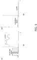
FIG. 5a is a graph of the power (current) supplied by discharge permission when a proper use signal is received, andFIG. 5b is a graph of when discharge is not permitted because a proper use signal could not be received. - The battery pack according to an embodiment of the present invention, and a battery system comprising this battery pack, will now be described through reference to
FIGS. 1 to 5b . - The
battery system 1 in this embodiment is a system in which power is supplied only to a specific power consumption element (avehicle 20 in this embodiment), and as shown inFIG. 1 , the system comprises abattery pack 10 and thevehicle 20. - As shown in
FIG. 1 , threebattery packs 10 are installed in the vehicle (power consumption element) 20, which is an electric motorcycle or the like. - The
vehicle 20 is propelled when power is supplied from the threebattery packs 10 installed in a space below aseat 20a, which rotationally drives the rear wheel (drive wheel) 26. - Also, the
vehicle 20 can make use of so-called battery swapping, in which battery packs 10 whose remaining capacity has been reduced due to use of the vehicle, spontaneous discharge, or the like are swapped for charged battery packs at a specific battery pack station. - Three of the
battery packs 10 of this embodiment are installed in thevehicle 20 in a state that allows them to be exchanged, in order to supply power to thevehicle 20. As shown inFIG. 2 , abattery pack 10 has areceiver 11, asignal analyzer 12, astorage component 13, and adischarge controller 14. - The
receiver 11 is capable of communicating with atransmitter 22 of thevehicle 20, and receives a proper use signal sent from thetransmitter 22. Then, when thebattery pack 10 is installed in a specific location on thevehicle 20, thereceiver 11 is in a state that allows communication with thetransmitter 22 on thevehicle 20 side. - The
signal analyzer 12 analyzes the proper use signal received from thevehicle 20 side at thereceiver 11. More specifically, thesignal analyzer 12 analyzes whether or not the signal received by thereceiver 11 matches the proper use signal, or whether or not a proper use signal was received by thereceiver 11. - Here, the
signal analyzer 12 performs analysis by comparing the waveform of the proper use signal received as a digital electric signal with the waveform of the received signal. - That is, the
signal analyzer 12 compares the waveform of the signal received by thereceiver 11 with the waveform of the proper use signal generated by asignal generator 21 of thevehicle 20 and stored ahead of time in thestorage component 13. When the waveform of the received signal matches the waveform of the proper use signal, it is determined that power is being supplied to thevehicle 20, which is the intended application of thebattery pack 10. - On the other hand, when the waveform of the received signal does not match the waveform of the proper use signal, this means that a signal other than a proper use signal has been received, and the
battery pack 10 is installed in an electrical product other than thespecific vehicle 20 that is the intended application. Therefore, in this case it is determined that thebattery pack 10 is not being used for thevehicle 20 for which it was intended. - Also, when the
receiver 11 cannot receive the proper use signal that it is supposed to receive, this also means that thebattery pack 10 is installed in an electrical product other than thespecific vehicle 20 for which it was intended. Therefore, in this case it is determined that thebattery pack 10 is not being used for thevehicle 20 for which it was intended. - The
storage component 13 stores in advance the waveform of the proper use signal generated by thesignal generator 21 of thevehicle 20 which is the intended application. Consequently, when a signal is received by thereceiver 11, thesignal analyzer 12 can read out the waveform of the proper use signal stored in advance from thestorage component 13 and compare it with the waveform of the received signal. - The
discharge controller 14 determines whether or not discharge to the connected electrical product is permitted, according to the analysis result of thesignal analyzer 12. - That is, the
discharge controller 14 determines whether or not to permit discharge according to the determination result by thesignal analyzer 12 as to whether or not the waveform of the signal received by thereceiver 11 matches the waveform of the proper use signal stored in thestorage component 13. - More specifically, when the waveform of the received signal matches the waveform of the proper use signal at the
signal analyzer 12, it is determined that thebattery pack 10 is supplying power to thevehicle 20 for which it was intended. Then, thedischarge controller 14 starts power supply to the connected electrical product (in the case ofFIG. 2 , the vehicle 20). - On the other hand, if it is determined that the
battery pack 10 is not being used for thevehicle 20 for which it was intended because the waveform of the received signal does not match the waveform of the proper use signal, thedischarge controller 14 halts the supply of power to the connected electrical product. - Also, if it is determined that the
battery pack 10 is not being used for thevehicle 20 for which it was intended because thereceiver 11 cannot receive a proper use signal, thedischarge controller 14 similarly halts the supply of power to the connected electrical product. - The processing for determining whether or not to permit discharge according to whether or not there is a proper use signal will be described in detail below.
- The
vehicle 20 is an electric motorcycle that is propelled when supplied with power from the threebattery packs 10 installed under theseat 20a, and as shown inFIG. 2 , it has thesignal generator 21, thetransmitter 22, apower input component 23, amotor 24, afront wheel 25, and a rear wheel (drive wheel) 26. - When the battery packs 10 are installed at a specific location in the
vehicle 20, thesignal generator 21 generates a proper use signal. Thesignal generator 21 then sends the generated proper use signal to thetransmitter 22. - Here, the proper use signal generated by the
signal generator 21 is a signal that serves as a condition for receiving the supply of power from the battery packs 10, and is generated as an electric digital signal having a specific waveform 4 (seeFIG. 4a , etc.). It is determined whether or not to permit the discharge of the battery packs 10, depending on whether or not a proper use signal has been received from thevehicle 20 side. - The
transmitter 22 transmits the proper use signal received from thesignal generator 21 to thereceiver 11 of the battery packs 10. - The
power input component 23 accepts the supply of power from the battery packs 10 by thedischarge controller 14 only when a specific condition is met as a result of the determination on thebattery pack 10 side. - The
motor 24 receives power supply from the battery packs 10 and transmits a rotational drive force to the axle of therear wheel 26, which is the drive wheel. - The
front wheel 25 is a steered wheel provided between the front part of thevehicle 20 and the road surface, and the travel direction can be varied by changing the orientation in conjunction with the orientation of thehandle bar 20b. - The
rear wheel 26 is a drive wheel provided between the road surface and the rear part of thevehicle 20 where the battery packs 10 are installed, and is rotationally driven by themotor 24. - With the
battery system 1 in this embodiment, whether or not power supply (discharge) to thevehicle 20 is permitted from the battery packs 10 is determined by performing communication between the battery packs 10 and thevehicle 20. - More specifically, as shown in
FIG. 3 , in step S11, first the battery packs 10 are put in a specific location in thevehicle 20. - Next, in step S12, the
signal generator 21 on thevehicle 20 side generates an electric digital signal (proper use signal). The proper use signal generated by thesignal generator 21 is then transmitted to thebattery pack 10 side via thetransmitter 22. - Next, in step S13, the
receiver 11 on thebattery pack 10 side receives the proper use signal. - Next, in step S14, the
signal analyzer 12 determines whether a proper usage signal was received by thereceiver 11. - More specifically, the
signal analyzer 12 determines whether or not the signal received by thereceiver 11 is a specific proper use signal. Alternatively, thesignal analyzer 12 determines whether or not thereceiver 11 has received a proper use signal. - The process of comparing the waveform of the proper use signal with the waveform of the received signal will be described below in detail.
- Whether or not the signal received by the
receiver 11 is a proper use signal is determined by comparing the waveform of the proper usage signal stored in thestorage component 13 of the battery packs 10 with the waveform of the received signal. - Next, in step S15, based on the result of the determination in step S14, the
signal analyzer 12 determines whether or not the battery packs 10 are being used for thevehicle 20 for which they were intended. - Specifically, in step S15, when a proper use signal has been received by the
receiver 11, thesignal analyzer 12 determines that the battery packs are being used for thevehicle 20 for which they were intended, and the flow proceeds to step S17. - On the other hand, if the
receiver 11 could not receive a proper use signal, or if a signal other than a proper use signal is received, thesignal analyzer 12 determines that the battery packs are not being used for thevehicle 20 for which they were intended, and the flow proceeds to step S16. - Here, in step S16, since it has been determined in step S15 that the battery packs are not being used for the
vehicle 20 for which they were intended, thedischarge controller 14 decides to halt discharge without permitting power supply (discharge) from the battery packs 10. - On the other hand, in step S17, since it has been determined in step S15 that the battery packs are being used for the
vehicle 20 for which they were intended, thedischarge controller 14 permits the supply (discharge) of power. - Next, in step S18, the determination in step S17 is received, and power supply (discharge) to the
vehicle 20 from thebattery pack 10 is commenced. - With the
battery pack 10 in this embodiment, as shown inFIG. 4a , when a proper use signal is received by thereceiver 11, discharge to thevehicle 20 is permitted as mentioned above, and power is supplied to thevehicle 20. -
FIG. 4a shows an example in which discharge from the battery packs 10 is permitted because the signal received by thereceiver 11 is a proper use signal. - That is, in
FIG. 4a , when a proper use signal is received by thereceiver 11, it is determined whether or not the waveform of the proper use signal (solid line) matches the waveform of the proper use signal stored in thestorage component 13. Since it is determined that there is a match, power (current) (dotted line) is supplied to thevehicle 20 as a result of permitting discharge from the battery packs 10. - On the other hand,
FIG. 4b shows an example in which discharge from the battery packs 10 is not permitted because the signal received by thereceiver 11 is a signal other than a proper use signal. - That is, in
FIG. 4b , it is determined whether or not the waveform of the received signal (solid line) matches the waveform of the proper use signal stored in thestorage component 13 when a signal has been received by thereceiver 11. Since it is determined here that there is no match, the power (current) (dotted line) to thevehicle 20 is halted as a result of the discharge from the battery packs 10 not being permitted. - Consequently, even when the
battery pack 10 is used for some application other than thespecific vehicle 20, for example, it is possible to prevent the supply of power to something other than thevehicle 20 to which has been transmitted a proper use signal whose signal waveform or the like has been registered in advance to thebattery pack 10. - Thus, even if some kind of signal is received by the
receiver 11, it is possible to determine whether or not power can be supplied depending on whether or not the waveform of this signal matches the waveform of the proper use signal. - As a result, it is possible to prevent power supply to some application other than what the
battery pack 10 was intended for, thereby solving problems such as decreasing the accuracy at which service life of the battery pack can be predicted, and to ensure the original performance of the battery pack. - With the
battery system 1 in this embodiment, as shown inFIG. 5a , when a proper use signal is received by thereceiver 11, discharge to thevehicle 20 is permitted and power is supplied to thevehicle 20, as described above. - The graph in
FIG. 5a shows the same details as the graph inFIG. 4a , so it will not be described again here. - On the other hand,
FIG. 5b shows an example in which discharge from thebattery pack 10 is not permitted because a proper use signal was not received by thereceiver 11. - That is, in
FIG. 5b , when thebattery pack 10 is put in thevehicle 20, no signal at all is received by thereceiver 11. Therefore, it is determined here that there is no reception of a proper use signal, so the power (current) (dotted line) to thevehicle 20 is halted as a result of the discharge from thebattery pack 10 not being permitted. - Consequently, even when the
battery pack 10 is used for some application other than thespecific vehicle 20, for example, it is possible to prevent the supply of power to something other than thevehicle 20 to which has been transmitted a proper use signal whose signal waveform or the like has been registered in advance to thebattery pack 10. - Thus, even if the battery packs 10 are put in something other than the
specific vehicle 20, since thereceiver 11 cannot receive a proper use signal, it can be easily determined whether or not power can be supplied. - As a result, it is possible to prevent power supply to some application other than what the
battery pack 10 was intended for, thereby solving problems such as decreasing the accuracy at which service life of the battery pack can be predicted, and to ensure the original performance of the battery pack. - An embodiment of the present invention was described above, but the present invention is not limited to or by the above embodiment, and various modifications are possible without departing from the gist of the invention.
- In the above embodiment, an example was given in which the
signal generator 21 on thevehicle 20 side generated a proper usage signal when the battery packs 10 were put at a specific location in thevehicle 20, but the present invention is not limited to this. - For example, the proper use signal may be generated by the
signal generator 21 when a starter switch or the like of thevehicle 20 is operated. - Here again, when the driver of the
vehicle 20 or someone else operates the starter switch, a proper use signal having a specific waveform is transmitted from thevehicle 20 side to thebattery pack 10 side, and as a result power begins to be supplied from the battery packs 10 to thevehicle 20. This starts up themotor 24 of thevehicle 20, and the vehicle is ready for use. - On the other hand, when the battery packs 10 are used for something other than the intended use, the battery packs 10 cannot receive the proper use signal, or receive a signal different from the proper use signal. Thus, in this case, just as in the above embodiment, power supply from the battery packs 10 to an application other than what was intended will not be performed.
- In the above embodiment, an example was given in which a digital signal was used as the proper use signal that was received in determining whether or not to permit discharge. However, the present invention is not limited to this.
- For example, an analog signal may be used as the proper use signal.
- In the above embodiment, an example was given in which an electrical signal was used as the proper use signal that was received in determining whether or not to permit discharge. However, the present invention is not limited to this.
- For example, some other signal, such as an optical signal or a magnetic signal, may be used as the proper use signal.
- In the above embodiment, an example was given in which three
battery packs 10 were installed in an electric motorcycle (vehicle 20) as a power consumption element. However, the present invention is not limited to this. - For example, one or two battery packs may be installed in the power consumption element, or four or more may be used.
- Also, a plurality of battery pack mounting components may be provided on the power consumption element side, and a number of battery packs corresponding to the required electrical capacity may be installed.
- Also, an example was given in which the three
battery packs 10 installed in thevehicle 20 were configured such that they were disposed under theseat 20a. However, the present invention is not limited to this, and the battery packs may be installed in the vehicle somewhere other than under the seat. - In the above embodiment, an example was given in which the battery packs 10 supplied power to an electric motorcycle as the power consumption element (vehicle 20). However, the present invention is not limited to this.
- For example, in addition to an electric motorcycle, the present invention may also be applied to a battery pack for supplying power to some other vehicle, such as an electric unicycle, an electric bicycle, an electric automobile (EV), or a PHV (plug-in hybrid vehicle).
- Alternatively, the power consumption element to which power is supplied from the battery pack of the present invention is not limited to a vehicle, and may instead be some other electrical product driven by a replaceable battery.
- In the above embodiment, an example was given in which whether or not the battery pack is being used properly was determined according to whether or not a proper use signal was received wirelessly by the 11. However, the present invention is not limited to this.
- For example, a means may be used for permitting discharge by determining whether or not the use is proper through the use of a signal that is switched on or off by plugging in the battery.
- The effect of the battery pack of the present invention is that the supply of power to anything other than the intended application can be prevented, so this invention can be widely applied to various electrical products and the like that are driven by a replaceable battery.
-
- 1 battery system
- 10 battery pack
- 11 receiver
- 12 signal analyzer
- 13 storage component
- 14 discharge controller
- 20 vehicle (power consumption element, electric motorcycle)
- 20a seat
- 20b handle bar
- 21 signal generator
- 22 transmitter
- 23 power input component
- 24 motor
- 25 front wheel
- 26 rear wheel (drive wheel)
- S step
Claims (7)
- A battery pack that supplies power to a specific power consumption element, comprising:a receiver configured to receive from the power consumption element a proper use signal generated in the power consumption element;a signal analyzer configured to analyze the proper use signal received by the receiver; anda discharge controller configured to permit power supply to the power consumption element when it has been determined, as a result of analysis by the signal analyzer, that a proper use signal has been received from the specific power consumption element.
- The battery pack according to Claim 1,
wherein the discharge controller does not supply power to the power consumption element if it is determined, as a result of analysis by the signal analyzer, that a signal other than a proper use signal has been received. - The battery pack according to Claim 1,
wherein the discharge controller does not supply power to the power consumption element if it is determined, as a result of analysis by the signal analyzer, that the proper use signal has not been received by the receiver. - The battery pack according to any of Claims 1 to 3,
wherein the proper use signal is generated as any of an optical signal, an electrical signal, and a magnetic signal. - The battery pack according to any of Claims 1 to 4,
wherein the proper use signal is generated as a digital signal or an analog signal. - A battery system, comprising:the battery pack according to any of Claims 1 to 5; anda power consumption element having a signal generator configured to generate the proper use signal to be transmitted to the receiver of the battery pack, and a transmitter configured to transmit the proper use signal to the receiver.
- The battery system according to Claim 6,
wherein the power consumption element is an electric motorcycle or an electric bicycle.
Applications Claiming Priority (2)
| Application Number | Priority Date | Filing Date | Title |
|---|---|---|---|
| JP2015224386A JP2017093253A (en) | 2015-11-17 | 2015-11-17 | Battery pack and battery system equipped with the same |
| PCT/JP2016/082607 WO2017086166A1 (en) | 2015-11-17 | 2016-11-02 | Battery pack and battery system provided therewith |
Publications (2)
| Publication Number | Publication Date |
|---|---|
| EP3379683A1 true EP3379683A1 (en) | 2018-09-26 |
| EP3379683A4 EP3379683A4 (en) | 2019-01-02 |
Family
ID=58718068
Family Applications (1)
| Application Number | Title | Priority Date | Filing Date |
|---|---|---|---|
| EP16866168.4A Pending EP3379683A4 (en) | 2015-11-17 | 2016-11-02 | Battery pack and battery system provided therewith |
Country Status (7)
| Country | Link |
|---|---|
| US (1) | US10875422B2 (en) |
| EP (1) | EP3379683A4 (en) |
| JP (1) | JP2017093253A (en) |
| MY (1) | MY194113A (en) |
| PH (1) | PH12018500490B1 (en) |
| TW (1) | TWI626811B (en) |
| WO (1) | WO2017086166A1 (en) |
Families Citing this family (7)
| Publication number | Priority date | Publication date | Assignee | Title |
|---|---|---|---|---|
| JP6597219B2 (en) | 2015-11-17 | 2019-10-30 | オムロン株式会社 | Battery pack and battery system including the same |
| JP6569490B2 (en) | 2015-11-17 | 2019-09-04 | オムロン株式会社 | Battery pack, battery system equipped with the same, and battery pack use determination method |
| US10615465B2 (en) * | 2016-09-23 | 2020-04-07 | Artisan Vehicle Systems Inc. | Battery management system |
| TWI658631B (en) * | 2018-01-08 | 2019-05-01 | 車王電子股份有限公司 | Battery pack |
| DE102019206412B4 (en) * | 2019-05-03 | 2026-03-05 | Volkswagen Aktiengesellschaft | Battery unit and communication method in one battery unit |
| EP4095974B1 (en) * | 2020-01-23 | 2025-04-02 | Panasonic Intellectual Property Management Co., Ltd. | Authentication method for power storage pack, power storage pack, charging device, electric moving body, and control device for electric moving body |
| CN114552708A (en) * | 2022-02-17 | 2022-05-27 | 深圳市杉川机器人有限公司 | Charging system and charging method |
Family Cites Families (42)
| Publication number | Priority date | Publication date | Assignee | Title |
|---|---|---|---|---|
| US4412137A (en) * | 1982-12-13 | 1983-10-25 | Eaton Corporation | Dual voltage engine starter management system |
| US6150793A (en) | 1996-02-29 | 2000-11-21 | Vehicle Enhancement Systems, Inc. | System and method for managing the electrical system of a vehicle |
| JP3910255B2 (en) * | 1997-04-18 | 2007-04-25 | 本田技研工業株式会社 | Battery rental system |
| US6429622B1 (en) | 2000-11-14 | 2002-08-06 | Telefonaktiebolaget L M Ericsson (Publ) | Method and apparatus for authenticating a charging unit by a portable battery-operated electronic device |
| US6629050B2 (en) * | 2001-02-13 | 2003-09-30 | Udt Sensors, Inc. | Vehicle safety and security system |
| JP2002291110A (en) * | 2001-03-26 | 2002-10-04 | Tokyo R & D Co Ltd | Method of collecting rental of battery |
| JP2006092850A (en) | 2004-09-22 | 2006-04-06 | Matsushita Electric Ind Co Ltd | Battery pack |
| JP2006236806A (en) | 2005-02-25 | 2006-09-07 | Matsushita Electric Ind Co Ltd | Secondary battery, secondary battery pack, and electronic device using the same |
| JP2007035479A (en) * | 2005-07-28 | 2007-02-08 | Nec Tokin Tochigi Ltd | Battery pack and battery-pack-dedicated device |
| JP4820175B2 (en) * | 2006-01-19 | 2011-11-24 | レノボ・シンガポール・プライベート・リミテッド | Battery pack and method for permanently stopping battery pack functionality |
| WO2009034877A1 (en) | 2007-09-10 | 2009-03-19 | Toyota Jidosha Kabushiki Kaisha | Vehicle charger and method for charging vehicle |
| JP2009186235A (en) | 2008-02-04 | 2009-08-20 | Ntt Docomo Inc | Mobile device and battery information display method |
| WO2010036202A1 (en) * | 2008-09-23 | 2010-04-01 | Stl Energy Technology (S) Pte Ltd | Battery pack and method of battery pack power management |
| JP2011086469A (en) * | 2009-10-15 | 2011-04-28 | Sony Corp | Battery pack |
| JP2012050267A (en) * | 2010-08-27 | 2012-03-08 | Denso Corp | Battery management device |
| JP4929389B2 (en) * | 2010-10-14 | 2012-05-09 | 三菱重工業株式会社 | Battery system |
| JP5685885B2 (en) * | 2010-10-21 | 2015-03-18 | 株式会社デンソー | Battery pack for vehicles |
| US9851412B2 (en) | 2010-11-09 | 2017-12-26 | International Business Machines Corporation | Analyzing and controlling performance in a composite battery module |
| US20120146582A1 (en) | 2010-12-08 | 2012-06-14 | Industrial Technology Research Institute | Systems and methods for charging battery systems of electric vehicles |
| JP2012159357A (en) | 2011-01-31 | 2012-08-23 | Canon Inc | Battery device |
| JP5730108B2 (en) * | 2011-04-07 | 2015-06-03 | 本田技研工業株式会社 | Vehicle battery authentication system |
| JP2012249369A (en) * | 2011-05-26 | 2012-12-13 | Toyota Industries Corp | Secondary battery power supply start-up circuit and cell balance device |
| JP2013025589A (en) * | 2011-07-21 | 2013-02-04 | Sanyo Information Technology Solutions Co Ltd | Vehicle monitoring system, vehicle monitoring device, vehicle, computer program and vehicle monitoring method |
| WO2013016570A1 (en) * | 2011-07-26 | 2013-01-31 | Gogoro, Inc. | Apparatus, method and article for authentication, security and control of power storage devices, such as batteries, based on user profiles |
| JP6096773B2 (en) * | 2011-07-26 | 2017-03-15 | ゴゴロ インク | Apparatus, method, and article for authentication, security, and control of power storage devices such as batteries |
| JP5670851B2 (en) | 2011-09-26 | 2015-02-18 | 日立オートモティブシステムズ株式会社 | Motor control device and vehicle control device |
| JP2013132147A (en) * | 2011-12-22 | 2013-07-04 | Sony Corp | Electric storage device, electronic apparatus, power system and electric vehicle |
| WO2013140781A1 (en) | 2012-03-19 | 2013-09-26 | パナソニック株式会社 | Method for monitoring storage cell, system for monitoring storage cell, and storage cell system |
| US20150180383A1 (en) | 2012-07-27 | 2015-06-25 | Panasonic Intellectual Property Management Co., Ltd. | Air blower equipped with brushless dc motor |
| JP2014030320A (en) | 2012-07-31 | 2014-02-13 | Denso Wave Inc | Vehicle charging system and vehicle charger |
| JP2014054082A (en) | 2012-09-07 | 2014-03-20 | Nissan Motor Co Ltd | Battery pack |
| JP6239241B2 (en) * | 2013-02-04 | 2017-11-29 | 株式会社東芝 | Battery performance estimation method and battery performance estimation apparatus |
| US10664562B2 (en) | 2013-02-24 | 2020-05-26 | Fairchild Semiconductor Corporation and University of Connecticut | Battery state of charge tracking, equivalent circuit selection and benchmarking |
| JP2014169059A (en) | 2013-03-05 | 2014-09-18 | Denso Corp | Vehicle function permission system |
| CN105027347B (en) * | 2013-03-07 | 2018-01-05 | Nec 能源元器件株式会社 | Nonaqueous electrolytic solution secondary battery |
| JP6065272B2 (en) | 2013-03-28 | 2017-01-25 | パナソニックIpマネジメント株式会社 | Storage battery pack, charging method, electrical equipment |
| US10630099B2 (en) | 2013-06-11 | 2020-04-21 | International Business Machines Corporation | Reducing conversion losses and minimizing load via appliance level distributed storage |
| JP6413311B2 (en) * | 2014-04-11 | 2018-10-31 | 株式会社村田製作所 | Power storage device, control method, control device, power storage system, electric vehicle, and electronic device |
| JP2014135895A (en) * | 2014-04-24 | 2014-07-24 | Nec Corp | Charge control system and method |
| TWI544717B (en) | 2014-09-12 | 2016-08-01 | 茂達電子股份有限公司 | Charging current setting method and charging module |
| JP6597219B2 (en) | 2015-11-17 | 2019-10-30 | オムロン株式会社 | Battery pack and battery system including the same |
| JP6569490B2 (en) | 2015-11-17 | 2019-09-04 | オムロン株式会社 | Battery pack, battery system equipped with the same, and battery pack use determination method |
-
2015
- 2015-11-17 JP JP2015224386A patent/JP2017093253A/en active Pending
-
2016
- 2016-11-02 WO PCT/JP2016/082607 patent/WO2017086166A1/en not_active Ceased
- 2016-11-02 MY MYPI2018700900A patent/MY194113A/en unknown
- 2016-11-02 US US15/759,000 patent/US10875422B2/en active Active
- 2016-11-02 EP EP16866168.4A patent/EP3379683A4/en active Pending
- 2016-11-02 PH PH1/2018/500490A patent/PH12018500490B1/en unknown
- 2016-11-11 TW TW105136741A patent/TWI626811B/en active
Also Published As
| Publication number | Publication date |
|---|---|
| US20180304764A1 (en) | 2018-10-25 |
| WO2017086166A1 (en) | 2017-05-26 |
| JP2017093253A (en) | 2017-05-25 |
| PH12018500490A1 (en) | 2018-09-10 |
| PH12018500490B1 (en) | 2024-06-21 |
| TWI626811B (en) | 2018-06-11 |
| EP3379683A4 (en) | 2019-01-02 |
| TW201720009A (en) | 2017-06-01 |
| US10875422B2 (en) | 2020-12-29 |
| MY194113A (en) | 2022-11-14 |
Similar Documents
| Publication | Publication Date | Title |
|---|---|---|
| US10875422B2 (en) | Battery pack, and battery system comprising the same | |
| US10661676B2 (en) | Guide device, guide system, and guide method | |
| US10670406B2 (en) | Control, apparatus for autonomously navigating utility vehicle | |
| EP3379684B1 (en) | Remaining battery capacity display device, battery system and remaining battery capacity display method | |
| EP3379682B1 (en) | Charge/discharge control device, charge/discharge control system, and charge/discharge control method | |
| US10683048B2 (en) | Electric bicycle, immobilizer for an electric bicycle and method for operating an electric bicycle | |
| EP3517353A1 (en) | Method of charging electric autonomous moving body | |
| KR101619618B1 (en) | Vehicle charger and method for controlling power thereof | |
| CN104139781B (en) | AEB control apparatus and method based on communication between vehicles | |
| US20160111908A1 (en) | Power supply apparatus for electric vehicle and method of controlling the same | |
| US10974788B2 (en) | Battery pack, battery system comprising the same, and method for distinguishing use application of battery pack | |
| US10166879B2 (en) | Battery discharge preventing system for hybrid vehicle and battery discharge preventing method using the same | |
| US9771124B2 (en) | Wheel rim-mounted regeneration coil-magnet system | |
| CN112534671A (en) | Presentation device, presentation method, and program | |
| CN108068637A (en) | Method, apparatus, system and the electronic equipment to charge for electric car | |
| US20180254647A1 (en) | Charge/discharge control device, charge/discharge control system, and remaining battery capacity adjustment method | |
| JP6097484B2 (en) | Charging system, in-vehicle device, charging device, vehicle | |
| JP2008067425A (en) | Electrical charge controller for vehicle | |
| CN109941290B (en) | Vehicle braking energy feedback control method and device and vehicle | |
| CN117901791A (en) | Power supply control device and vehicle with same | |
| KR20160131723A (en) | Charging apparatus and charging control apparatus for electric vehicle | |
| JP7079230B2 (en) | Valuation Guarantee Device, Valuation Guarantee Method, and Program | |
| CA3019397C (en) | Device and method for regulating a battery charging process | |
| JP2021112086A (en) | Power supply system of vehicle | |
| EP2819264A1 (en) | Vehicle-mounted charging device, and vehicle mounted with same |
Legal Events
| Date | Code | Title | Description |
|---|---|---|---|
| STAA | Information on the status of an ep patent application or granted ep patent |
Free format text: STATUS: THE INTERNATIONAL PUBLICATION HAS BEEN MADE |
|
| PUAI | Public reference made under article 153(3) epc to a published international application that has entered the european phase |
Free format text: ORIGINAL CODE: 0009012 |
|
| STAA | Information on the status of an ep patent application or granted ep patent |
Free format text: STATUS: REQUEST FOR EXAMINATION WAS MADE |
|
| 17P | Request for examination filed |
Effective date: 20180305 |
|
| AK | Designated contracting states |
Kind code of ref document: A1 Designated state(s): AL AT BE BG CH CY CZ DE DK EE ES FI FR GB GR HR HU IE IS IT LI LT LU LV MC MK MT NL NO PL PT RO RS SE SI SK SM TR |
|
| AX | Request for extension of the european patent |
Extension state: BA ME |
|
| A4 | Supplementary search report drawn up and despatched |
Effective date: 20181129 |
|
| RIC1 | Information provided on ipc code assigned before grant |
Ipc: B60L 3/00 20060101ALI20181123BHEP Ipc: B60L 11/18 20060101ALI20181123BHEP Ipc: H02J 7/00 20060101AFI20181123BHEP Ipc: H01M 10/42 20060101ALI20181123BHEP Ipc: B60L 3/04 20060101ALI20181123BHEP |
|
| DAV | Request for validation of the european patent (deleted) | ||
| DAX | Request for extension of the european patent (deleted) | ||
| STAA | Information on the status of an ep patent application or granted ep patent |
Free format text: STATUS: EXAMINATION IS IN PROGRESS |
|
| 17Q | First examination report despatched |
Effective date: 20201125 |
|
| REG | Reference to a national code |
Ref country code: DE Ref legal event code: R079 Free format text: PREVIOUS MAIN CLASS: H02J0007000000 Ipc: B60L0003040000 |
|
| RIC1 | Information provided on ipc code assigned before grant |
Ipc: H01M 10/48 20060101ALI20230214BHEP Ipc: H01M 10/42 20060101ALI20230214BHEP Ipc: B60L 53/65 20190101ALI20230214BHEP Ipc: H02J 7/00 20060101ALI20230214BHEP Ipc: B60L 53/80 20190101ALI20230214BHEP Ipc: B60L 3/04 20060101AFI20230214BHEP |