EP3379672A1 - Efficient pre-charging of sections of a dc network - Google Patents
Efficient pre-charging of sections of a dc network Download PDFInfo
- Publication number
- EP3379672A1 EP3379672A1 EP17162603.9A EP17162603A EP3379672A1 EP 3379672 A1 EP3379672 A1 EP 3379672A1 EP 17162603 A EP17162603 A EP 17162603A EP 3379672 A1 EP3379672 A1 EP 3379672A1
- Authority
- EP
- European Patent Office
- Prior art keywords
- sections
- transmission path
- switching
- precharge circuit
- energy transmission
- Prior art date
- Legal status (The legal status is an assumption and is not a legal conclusion. Google has not performed a legal analysis and makes no representation as to the accuracy of the status listed.)
- Withdrawn
Links
Images


Classifications
-
- H—ELECTRICITY
- H02—GENERATION; CONVERSION OR DISTRIBUTION OF ELECTRIC POWER
- H02J—CIRCUIT ARRANGEMENTS OR SYSTEMS FOR SUPPLYING OR DISTRIBUTING ELECTRIC POWER; SYSTEMS FOR STORING ELECTRIC ENERGY
- H02J1/00—Circuit arrangements for dc mains or dc distribution networks
- H02J1/10—Parallel operation of dc sources
- H02J1/108—Parallel operation of dc sources using diodes blocking reverse current flow
-
- H—ELECTRICITY
- H02—GENERATION; CONVERSION OR DISTRIBUTION OF ELECTRIC POWER
- H02J—CIRCUIT ARRANGEMENTS OR SYSTEMS FOR SUPPLYING OR DISTRIBUTING ELECTRIC POWER; SYSTEMS FOR STORING ELECTRIC ENERGY
- H02J1/00—Circuit arrangements for dc mains or dc distribution networks
- H02J1/06—Two-wire systems
-
- H—ELECTRICITY
- H02—GENERATION; CONVERSION OR DISTRIBUTION OF ELECTRIC POWER
- H02J—CIRCUIT ARRANGEMENTS OR SYSTEMS FOR SUPPLYING OR DISTRIBUTING ELECTRIC POWER; SYSTEMS FOR STORING ELECTRIC ENERGY
- H02J7/00—Circuit arrangements for charging or depolarising batteries or for supplying loads from batteries
- H02J7/007—Regulation of charging or discharging current or voltage
Definitions
- the present invention is based on a precharge circuit for a plurality of sections of a DC voltage network, which can be connected to each other individually and in groups via a respective switching element and can be separated from one another.
- DC power networks are often used for power distribution.
- the energy distribution by DC voltage has some advantages over an energy distribution by AC voltage.
- the energy exchange between individual sections of the network is simpler. In particular, there is no need to coordinate the frequency and the phase position of the individual sections to one another.
- Such a DC voltage network usually consists of a plurality of sections, which can each be separated from each other by a switching device and connected to each other.
- the sections can have a wide variety of energy sources (for example a photovoltaic system) or energy stores (for example batteries) and a wide variety of consumers.
- energy sources for example a photovoltaic system
- energy stores for example batteries
- consumers there is also a connection to a three-voltage network supplying the DC voltage network via an inverter.
- the connection to the three-phase voltage network can be regarded as a section within the meaning of the present invention.
- the sections may have capacitive energy stores that are precharged before connecting one section to the other sections.
- the voltage of the respective section is thereby adjusted to the voltage of the other sections so far that the connection of the respective section with the other sections only leads to a small compensation current.
- precharging circuits are used for precharging the capacitive energy store.
- the precharging of the capacitive energy storage, the switching element for each section a respective Vorladescrien connected in parallel.
- the precharge circuit typically consists of a series connection of an electronic or electromechanical switch and a resistor.
- the object of the present invention is to provide possibilities by means of which the pre-charging of the sections can be realized simply, efficiently and cost-effectively.
- This configuration ensures that whenever the switching device switches the energy transmission path to the conductive state, the section with the lowest voltage coupled to the energy transmission path - and only this section - from the section with the highest voltage coupled to the energy transmission path - and only from this Section - is preloaded.
- the energy transmission path is preferably designed as an inductive energy transmission path. This allows efficient and low-loss energy transfer from one section to the other section.
- the switching device is preferably arranged in the energy transmission path. As a result, the switching device can be configured very simply.
- both potentials of the section connected to the respective diode group can be coupled to the energy transmission path via the diode groups.
- the energy transmission path is preferably galvanically isolated from the diode groups. The advantages of galvanic isolation are readily apparent.
- the switching device preferably has a plurality of sub-switching devices, which are each assigned to a diode group. This results in a simple design of the switching device.
- the sub-switching devices are individually controlled by the control device. Preferably, however, a uniform control takes place. This embodiment simplifies the design and control of the precharge circuit.
- the partial switching devices preferably connect the section connected to the respective diode group to the energy transmission path in the manner of an inverter on the basis of the control signal transmitted by the control device.
- a resistance and a further switching device assigned to the resistor are assigned to the energy transmission path, so that the energy transmission path acts as a consumer when the further switching device is closed.
- the precharge circuit can also be used as a discharge circuit for the sections.
- At least a part of the switching elements is designed such that, depending on the switching state of the respective switching element, they separate or connect only one of two potentials of the sections and permanently connect the other potential of the sections. It is also possible that at least a part of the switching elements is designed such that they separate depending on the switching state of the respective switching element both potentials of the sections from each other or connect with each other.
- the two designs are mutually exclusive for a single switching element.
- a part according to the first-mentioned embodiment and a part complementary thereto according to the second-named embodiment may be formed by a plurality of switching elements.
- the present invention relates - generally speaking - an electro-technical facts. Terms such as “connected” and “separated” or “isolated” and the like are therefore always meant in the electrical sense, not in the mechanical sense.
- a DC voltage network has a plurality of sections 1.
- the sections 1 are in the representation of FIG. 1 additionally supplemented with a single small letter.
- the reference number supplemented by the corresponding small letter is used, that is, for example, the reference numeral 1c or the reference numeral 1f.
- the reference numeral 1c or the reference numeral 1f is used without the addition of a small letter.
- the DC voltage network has a central section.
- the central section 1a represents the "hub” for the other sections 1.
- the central section 1a is therefore common to the other sections 1.
- FIG. 1 the sections 1, similar to a tree structure branches and ramifications form.
- the section 1d is divided into further sections 1e to 1h.
- several sections 1 can be connected in series. In the presentation of FIG. 1 these are the sections 1k and 11.
- the "section" 1m represents the connection of the central section 1a to an AC mains - here a three-phase system - is.
- the nature of the sections 1 may be determined as needed. However, they usually each have an electrical energy storage 2.
- the energy storage 2 may be, for example, a battery or a capacitor.
- the sections 1 usually continue to have at least one energy source 3 and / or at least one consumer 4.
- An example of an energy source 3 is a photovoltaic system or a (charged) Battery.
- Examples of consumers 4 are an electric drive, a heater and an (uncharged) battery.
- other energy sources 3 and other consumers 4 may also be present. Combinations are possible.
- FIG. 1 only for one of the sections 1 of the energy storage 2, the power source 3 and the consumer 4 located.
- the corresponding units 2, 3 and 4 can also be present in the other sections 1.
- the DC voltage network has in each case a switching element 5 for the sections 1.
- the respective section 1 can be connected to at least one other section 1 and separated from the at least one other section 1 via the respective switching element 5.
- the sections 1b to 11 can be connected directly or indirectly via other sections 1 to the central section 1a or separated from it.
- the connection or disconnection of the switching member 5 of the portion 1f causes the connection or disconnection of the portion 1f to and from the portion 1d.
- the section 1f is thereby connected to the central section 1a via the section 1d or separated from it or separated from it by the section 1d or without any further connection to the central section 1a.
- the sections 1 Due to the configuration as a direct voltage network, the sections 1 have a positive potential P1 and a negative potential P2.
- the potentials P1, P2 are drawn only for sections 1a and 1f. Lines of the sections 1, which have similar potentials P1, P2, can be interconnected via the switching elements 5, so for example the positive potential P1 of one of the sections 1 with the positive potentials P1 of the other sections 1 and also the negative potential P2 of this section. 1 with the negative potential P2 of the other sections 1.
- the switching elements 5 are corresponding FIG. 2 educated.
- the respective switching element 5 is formed such that it - depending on the switching state - only the positive potential P1 of each section 1 from the positive potential P1 of the other sections 1 separates or connects to the positive potential P1 of the other sections 1.
- the negative potentials P2 of sections 1 are permanently connected.
- only a single-pole separation of the respective section 1 from the other sections 1 takes place.
- only one (1) switching path is present.
- it can always be assumed that the positive potential P1 is the switched potential, while the negative potential P2 is unswitched. In principle, however, the reverse procedure is possible.
- the switching elements 5 are corresponding FIG. 3 educated.
- the respective switching element 5 is designed such that it - depending on the switching state - both the positive potential P1 of each section 1 from the positive potential P1 of the other sections 1 separates or connects to the positive potential P1 of the other sections 1 and the negative Potential P2 of each section 1 of the negative potential P2 of the other sections 1 separates or with the negative potential P2 of the other sections 1 connects.
- the embodiment according to FIG. 3 Thus, if necessary, a two-pole separation of the respective section 1 from the other sections 1 takes place. Thus, there are two switching paths.
- all switching elements 5 are formed uniformly and identically, so either all realize only a single-pole separation of the respective section 1 of the other sections 1 or all realize a two-pole separation of the respective section 1 of the other sections 1.
- mixed forms are also possible, that is, a part of the switching elements 5 realizes a unipolar separation of the respective section 1 from the other sections 1 and another part of the switching elements 5 realizes a two-pole separation of the respective section 1 from the other sections 1.
- the switching devices 5 for the sections 1e to 1h each cause a bipolar separation, while the switching elements 5 of the sections 1a to 1d and 1i to 1m cause only a single-pole separation.
- the switching elements 5, as shown in the FIGS. 2 and 3 usually for each switching path in each case an electronic switch assembly 6. Furthermore, the switching elements 5, seen from the electronic switch assembly 6, at least to each associated portion 1 out towards an electromechanical switch 7.
- the respective electronic switch arrangement 6 and the respective electromechanical switch 7 are thus connected in series.
- a series circuit of two electromechanical switches 7 and an electronic switch assembly 6 may be present.
- the electronic switch assembly 6 is arranged in the middle of the series connection.
- the electronic switch assembly 6 may for example consist of two series-connected electronic switches 8, which in each case a diode 9 is connected in parallel.
- the two diodes 9 are polarized antiparallel to each other in this case. Regardless of the control of the two electronic switches 8 thus always locks one of the two diodes 9.
- the electronic switch 8, for example, as shown in the FIGS. 2 and 3 be designed as IGBTs. However, other embodiments are possible, for example as MOSFETs.
- the diodes 9 may be intrinsic components of the electronic switches 8. Alternatively, it may be independent electronic components.
- the positive potentials P1 are equal to each other and also the negative potentials P2 equal to each other.
- the potential difference U between the positive and negative potentials P1 and P2 is thus the same for the sections 1.
- the voltage U should be equal to a nominal value if possible.
- the nominal value can be selected as needed. For example, it may be 24V, 100V, 500V, or any other suitable value.
- the positive potential P1 in this case can have individual values for the sections 1 or, if appropriate, groups of sections 1. In the case of bipolar separation, this also applies to the negative potential P2.
- the voltage U In both cases - ie both in the single-pole separation and in the two-pole separation - the voltage U, however, individually for the respective section 1 or the respective group of sections 1 each have their own value.
- the DC voltage network therefore has a precharge circuit 10.
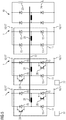
- the following will be in connection with the FIG. 4 and 5 two possible embodiments of the precharge circuit 10 explained.
- the precharge circuit 10 of FIG. 4 has diode groups 11, a switching device 12, a power transmission path 13 and a control device 14.
- the number of diode groups 11 may be determined as needed. In the FIG. 4 shown number of three diode groups 11 is purely exemplary.
- the sections 1 of the DC voltage network are each connected to at least one of the diode groups 11 of the precharge circuit 10. Via the respective diode group 11, the sections 1 of the DC voltage network are coupled to the energy transmission path 13.
- the energy transmission path 13 is the same for the diode groups 11 and thus also for the sections 1 the same.
- the diode groups 11 for coupling in each case a single section 1 to the energy transmission path 13 may in the embodiment according to FIG. 4
- the respective section 1 is in this case connected to a node 16 which is arranged between the two diodes 15 of the respective diode group 11.
- the reference numerals for the diodes 15 and the node 16 are shown in FIG FIG. 4 drawn only for one diode group 11.
- the switching elements 5 of the sections 1 as shown in the FIGS. 2 and 3 each have a tap 17, which is arranged between the respective electronic switching device 6 and the respective electromechanical switch 7 of the respective switching path.
- the sections 1 can be connected via the respective tap 17 to the node 16 of the respective diode group 11.
- the switching paths of the switching elements 5, viewed in each case from the electronic switch arrangement 6, in each case have an electromechanical switch 7 in both directions
- the switching paths preferably also each have two taps 17.
- One of the two taps 17 is in this case arranged between the electronic switch arrangement 6 and the one electromechanical switch 7 and between the electronic switch arrangement 6 and the other electromechanical switch 7.
- the two taps 17 are connected in this case with different diode groups 11 of the precharge circuit 10.
- the control device 14 transmits a control signal S to the switching device 12.
- the switching device 12 is controlled such that it switches the energy transmission path 13 conductive. This effect is automatically obtained for all coupled to the energy transmission path 13 sections 1 of the DC voltage network.
- the switching device 12 may be disposed in the power transmission path 13.
- the switching device 12 may in the embodiment according to FIG. 4 For example, be designed as a simple electronic switch, in particular as an IGBT or as a MOSFET.
- a current-limiting element 18 is arranged in the energy transmission path 13.
- the current limiting element 18 may be formed as a resistor.
- the energy transmission path 13 is formed as a resistive energy transmission path.
- the current-limiting element 18 is designed as a throttle.
- the energy transmission path 13 is formed as an inductive energy transmission path.
- the element 18 In the case of the - preferred - embodiment of the current-limiting element 18 as a throttle, the element 18 strictly speaking, not the current I as such, but only its rise. Due to the fact that in the energy transmission path 13 of FIG. 4 no appreciable current limiting occurs, the current I flowing across the energy transfer path 13 can thus assume large values.
- a monitoring device 19 is present, which optionally the switching device 12 temporarily locks.
- the monitoring device 19 does not cause a permanent blocking of the switching device 12, but only serves to protect the pre-charge circuit 10 against overload.
- the monitoring device 19 can bring about a current limitation in the energy transmission path 13 and / or a temperature limitation of the switching device 12.
- the monitoring device 19 may be designed, for example, in the manner of a current regulator.
- the free-wheeling diode 20 is further connected in parallel to the current-limiting element 18.
- the freewheeling diode 20 can, for example, only bridge the current-limiting element 18. According to FIG. 4 the freewheeling diode 20 is connected to the negative potential P2.
- a capacitor 21 is still present.
- the capacitor 21 is used for commutation. It can be dimensioned so small that a pre-charging of the capacitor 21 is not required.
- a capacitor 22 may be present.
- the capacitor 22 serves to decouple the intrinsic inductances of the input lines of the pre-charge circuit 10.
- the energy transmission path 13 may additionally be assigned a resistor 23 and a further switching device 24 assigned to the resistor 23. Due to the presence of the series connection of the resistor 23 and the other switching device 24, it is possible to use the pre-charge circuit 10 as needed alternatively for pre-charging the sections 1 and for discharging the sections 1, depending on whether the resistor 23 via the further switching device 24 with the negative potential P2 is connected or disconnected from it.
- the energy transmission path 13 can thus act as a consumer when the other switching device 24 is closed.
- the embodiment of the Vorladescrien 10 according to FIG. 4 is only possible if by means of the switching elements 5 of the corresponding sections 1 only a single-pole separation of the sections 1 from each other.
- the configuration of the precharge circuit 10 is according to FIG. 5 always feasible, so both when using the switching elements 5 of the corresponding sections 1 only a one-pole separation of the sections 1 from each other, as well as when by means of the switching elements 5 of the corresponding sections 1 a two-pole separation of the sections 1 from each other.
- the precharge circuit 10 of FIG. 4 also has the precharge circuit 10 of FIG. 5 Diode groups 11, a switching device 12, a power transmission path 13 and a control device 14.
- the sections 1 of the DC voltage network are each connected to at least one of the diode groups 11 of the precharge circuit 10. Via the respective diode group 11, the sections 1 of the DC voltage network are coupled to the energy transmission path 13.
- the energy transmission path 13 is the same for the diode groups 11 and thus also for the sections 1 the same.
- the diode groups 11 for coupling in each case a single section 1 to the energy transmission path 13 may in the embodiment according to FIG. 5
- the respective section 1 is connected in this case with two nodes 16, which are arranged at the outputs of the bridge rectifier.
- the sections 1 of the DC voltage network are each connected to at least one of the diode groups 11 of the precharge circuit 10.
- the switching elements 5 of the sections 1 as shown in FIG. 3 in their two switching paths each have a tap 17, which is between the respective electronic switch assembly 6 and the respective electromechanical Switch 7 of the respective switching path is arranged.
- the sections 1 can be connected via the respective tap 17 to the node 16 of the respective diode group 11.
- taps 17 may be present and each one of the two taps 17 with one of the two nodes 16 may be connected.
- both potentials P1, P2 of the corresponding sections 1 are coupled to the energy transmission path 13 via the diode groups 11.
- the energy transmission path 13 is in the case of the embodiment of FIG. 5 from the diode groups 11 potential decoupled or galvanically isolated.
- the energy transmission path 13 in the case of the embodiment of FIG. 5 be designed in the manner of a transformer core, wherein in the bridge arms of the bridge rectifier windings 25 are arranged.
- the energy transmission path 13 is designed as an inductive energy transmission path.
- the windings 25 act - depending on the direction of the energy flow - as a primary winding or as a secondary winding of the transformer.
- the windings 25 have the same number of turns. It is therefore via the windings 25 and the energy transmission path 13 Although a potential decoupling, but no voltage transformation.
- the switching device 12 has a plurality of partial switching devices.
- the sub-switching devices are each assigned to a diode group 11. They each include two electronic switches 26, which are each connected in parallel to a diode 15. The two electronic switches 26 are arranged crosswise with respect to the bridge rectifier.
- the electronic switches 26 may be formed, for example, as an IGBT or as a MOSFET.
- the control device 14 transmits a control signal S to the switching device 12, by means of which the switching device 12 is controlled such that it switches the energy transmission path 13 to be conductive.
- the control signal S can cause the sub-switching devices to connect the section 1 connected to the respective diode group 11 in the manner of an inverter to the energy transmission path 13.
- the partial switching devices are preferably controlled uniformly by the control device 14. From the point of view of the control device 14, therefore, preferably only a single control signal S is output.
- the switching device 12 turns the power transmission path 13 conductive, feeds - as well as in the embodiment of FIG. 4 - Only that portion 1 energy in the energy transmission path 13, which has the highest voltage U.
- the switching device 12 draws energy from the energy transmission path 13, which has the lowest voltage U. This effect is automatically obtained for all coupled to the energy transmission path 13 sections 1 of the DC voltage network. As before, it can be determined by appropriate control of the electromechanical switch 7 of the switching elements 5, which sections 1 can ever be preloaded.
- monitoring devices 27 are preferably assigned to the subcircuit devices.
- the monitoring devices 27 only act on the respective partial switching device and lock it temporarily if necessary.
- the monitoring devices 27 do not cause a permanent blocking of the respective sub-switching device, but only serves to protect the respective sub-switching device against overload.
- the mode of operation of the monitoring devices 27 is analogous to the mode of operation of the monitoring device 19.
- each diode group 11 is assigned in each case a partial switching device.
- each diode group 11 is assigned in each case a partial switching device.
- the coupled sections 1 can only be precharged.
- the sections 1 coupled to these diode groups 11 can not feed electrical energy into the energy transmission path 13. If such diode groups 11 - ie diode groups 11 without associated partial switching device - are present, it is possible to mark the corresponding diode groups 11 accordingly, so that incorrect connections are avoided.
- Analogous to the embodiment of FIG. 4 can also in the design of FIG. 5 the energy transmission path 13 in addition, a resistor 23 and the resistor 23 associated with another switching device 24 be assigned. Due to the presence of the series connection of the resistor 23 and the other switching device 24, it is the same as in FIG. 4 it is possible to use the precharge circuit 10 alternatively as needed to pre-charge the sections 1 and to discharge the sections 1, depending on whether the resistor 23 is activated via the further switching device 24 or remains deactivated.
- the energy transmission path 13 can thus act as a consumer when the other switching device 24 is closed. If, however, sections 1 are coupled to the energy transmission path 13 exclusively via diode groups 11, that is to say that no subcircuit devices are assigned to them, these sections 1 can not be discharged via the resistor 23.
- the present invention has many advantages. For example, by means of the precharge circuit according to the invention it is possible to charge several sections 1 of the DC voltage network at the same time. In this case, it is ensured by the monitoring devices 19, 27 that the design limits of the precharge circuit 10 are not exceeded.
- the system is modular. In particular, multiple precharge circuits 10 may be used. For example, it is possible to use multiple precharge circuits 10 to increase the effective current. It is also possible to pre-load different groups of sections 1 via their own precharge circuit 10. For example, one precharge circuit 10 could be connected to the sections 1b to 1h, another precharge circuit 10 could be connected to the sections 1a, 1d and 1i to 1m.
- the precharge circuits 10 may in this case possibly be designed differently, that is, for example, once each according to FIG. 4 and FIG. 5 , In the case of the embodiment of the Vorladescrien 10 according to FIG. 5 Furthermore, it is possible to couple a separate energy source specifically for pre-charging the sections 1 to the energy transmission path 13.
- the winding 25 for coupling the power source can be adapted in this case with respect to their number of turns to the rated voltage of the power source in relation to the rated voltage of the DC power grid.
- the configuration of the precharge circuit 10 is very simple. The dimensioning of the precharge circuit 10 can be done as needed. Regardless of the dimensioning, however, even batteries included in sections 1 or other larger energy storage devices can be pre-charged.
- the diode groups 11 and, corresponding thereto, the inputs of the precharge circuit 10 do not have to be designed for the full power of the precharge circuit 10. If the corresponding necessity arises, it is possible, for example, to connect a specific section 1 of the DC voltage network-for example, section 1c-to two or three diode groups 11.
- a numerical example Assume that the switching device 12 and the energy transmission path 13 are dimensioned for an energy transfer of 1.5 kW, the diode groups 11 but dimensioned only for each 500 W.
- a specific section 1 of the DC voltage network is connected to three diode groups 11, it is possible to realize the full power transmission of 1.5 kW between this section 1 of the DC voltage network and the precharge circuit 10. It is even possible to dimension the diode groups 11 differently, for example a diode group 11 for a power transmission of 1.0 kW and another diode group 11 for a Energy transfer of 500 W.
- the sections 1 are always charged to the voltage U of the section 1 with the highest voltage U.
- the voltages of the sections 1 within the pre-charge circuit 10 can be measured and utilized for display, diagnostic or control purposes or transmitted to a higher-level device (for example a network management). It is also possible to give a message when the summons of the sections 1 is completed. It is also possible to end the pre-charging automatically when the duty cycle of the switching device 12 exceeds a predetermined value. In the case of the embodiment according to FIG. 4 Furthermore, it is possible to terminate the pre-charging automatically when the voltage difference across the diode groups 11 drops Threshold falls below or at the foot of the diode groups 11 adjusting potential has a sufficient distance from the negative potential P2. Starting the precharge can satisfy inverse conditions. In order to avoid a constant switching back and forth, the respective switching state of the precharge circuit 10 may be maintained for a minimum time or a hysteresis behavior may be implemented, if necessary.
Abstract
Ein Gleichspannungsnetz weist eine Mehrzahl von Abschnitten (1) auf, die über ein jeweiliges Schaltorgan (5) einzeln oder gruppenweise miteinander verbindbar und voneinander trennbar sind. Eine Vorladeschaltung (10) weist Diodengruppen (11), eine Schalteinrichtung (12), einen Energieübertragungspfad (13) und eine Steuereinrichtung (14) auf. Jeweils einer der Abschnitte (1) des Gleichspannungsnetzes ist über jeweils mindestens eine der Diodengruppen (11) an den Energieübertragungspfad (13) angekoppelt. Der Energieübertragungspfad (13) ist für die Diodengruppen (11) einheitlich derselbe. Die Steuereinrichtung (14) übermittelt zum Vorladen von Abschnitten (1) ein Steuersignal (S) an die Schalteinrichtung (12). Die Schalteinrichtung (12) schaltet dadurch den Energieübertragungspfad (13) für alle an den Energieübertragungspfad (13) angekoppelten Abschnitte (1) leitend.

Description
Die vorliegende Erfindung geht aus von einer Vorladeschaltung für eine Mehrzahl von Abschnitten eines Gleichspannungsnetzes, die über ein jeweiliges Schaltorgan einzeln oder gruppenweise miteinander verbindbar und voneinander trennbar sind.The present invention is based on a precharge circuit for a plurality of sections of a DC voltage network, which can be connected to each other individually and in groups via a respective switching element and can be separated from one another.
Die vorliegende Erfindung geht weiterhin aus von einem Gleichspannungsnetz,
- wobei das Gleichspannungsnetz eine Mehrzahl von Abschnitten aufweist,
- wobei das Gleichspannungsnetz für die Abschnitte jeweils ein Schaltorgan aufweist, über das der jeweilige Abschnitt mit den anderen Abschnitten verbindbar und von ihnen trennbar ist,
- wobei das Gleichspannungsnetz eine derartige Vorladeschaltung aufweist.
- wherein the DC voltage network has a plurality of sections,
- wherein the DC voltage network for the sections in each case has a switching element, by means of which the respective section can be connected to and separable from the other sections,
- wherein the DC voltage network comprises such a precharge circuit.
Innerhalb geschlossener Systeme (beispielsweise innerhalb von Fabrikanlagen) werden zur Energieverteilung in vielen Fällen Gleichspannungsnetze eingesetzt. Die Energieverteilung durch Gleichspannung hat gegenüber einer Energieverteilung durch Wechselspannung einige Vorteile. Beispielsweise ist der Energieaustausch zwischen einzelnen Abschnitten des Netzes einfacher. Insbesondere muss keine Abstimmung von Frequenz und Phasenlage der einzelnen Abschnitte aufeinander erfolgen.Within closed systems (for example, inside factories) DC power networks are often used for power distribution. The energy distribution by DC voltage has some advantages over an energy distribution by AC voltage. For example, the energy exchange between individual sections of the network is simpler. In particular, there is no need to coordinate the frequency and the phase position of the individual sections to one another.
Ein derartiges Gleichspannungsnetz besteht in der Regel aus einer Mehrzahl von Abschnitten, die jeweils durch ein Schaltorgan voneinander getrennt und miteinander verbunden werden können. Die Abschnitte können die verschiedensten Energiequellen (beispielsweise eine Photovoltaikanlage) oder Energiespeicher (beispielsweise Batterien) und die verschiedensten Verbraucher aufweisen. Oftmals besteht auch über einen Umrichter eine Anbindung an ein das Gleichspannungsnetz speisendes Drehspannungsnetz. Auch die Anbindung an das Drehspannungsnetz kann als Abschnitt im Sinne der vorliegenden Erfindung angesehen werden.Such a DC voltage network usually consists of a plurality of sections, which can each be separated from each other by a switching device and connected to each other. The sections can have a wide variety of energy sources (for example a photovoltaic system) or energy stores (for example batteries) and a wide variety of consumers. Often, there is also a connection to a three-voltage network supplying the DC voltage network via an inverter. The connection to the three-phase voltage network can be regarded as a section within the meaning of the present invention.
Wenn das Gleichspannungsnetz heruntergefahren ist oder vom Drehstromnetz getrennt ist oder wenn verschiedene Abschnitte des Gleichspannungsnetzes voneinander getrennt sind, kann die Situation auftreten, dass die einzelnen Abschnitte voneinander verschiedene Spannungen aufweisen. Die Abschnitte dürfen in einem derartigen Fall nicht ohne weiteres zusammengeschaltet werden, da dies zumindest kurzzeitig extrem hohe Ausgleichsströme zur Folge hätte.When the DC power supply is shut down or disconnected from the three-phase power supply, or when different sections of the DC power supply are disconnected, the situation may occur that the individual sections have different voltages from each other. The sections may not be readily interconnected in such a case, since this would result in extremely high compensation currents at least for a short time.
Um die Ausgleichsströme niedrig zu halten oder nach Möglichkeit sogar ganz zu vermeiden, können die Abschnitte kapazitive Energiespeicher aufweisen, die vor dem Verbinden eines jeweiligen Abschnitts mit den anderen Abschnitten vorgeladen werden. Die Spannung des jeweiligen Abschnitts wird dadurch so weit an die Spannung der anderen Abschnitte angeglichen, dass das Verbinden des jeweiligen Abschnitts mit den anderen Abschnitten nur noch zu einem geringen Ausgleichsstrom führt.To keep the equalization currents low or even avoid them altogether, the sections may have capacitive energy stores that are precharged before connecting one section to the other sections. The voltage of the respective section is thereby adjusted to the voltage of the other sections so far that the connection of the respective section with the other sections only leads to a small compensation current.
Im Stand der Technik werden zum Vorladen der kapazitiven Energiespeicher Vorladeschaltungen verwendet. Üblicherweise ist zum Vorladen des kapazitiven Energiespeichers dem Schaltorgan für den jeweiligen Abschnitt eine jeweilige Vorladeschaltung parallel geschaltet. Die Vorladeschaltung besteht in der Regel aus einer Reihenschaltung eines elektronischen oder elektromechanischen Schalters und eines Widerstands.In the prior art, precharging circuits are used for precharging the capacitive energy store. Usually, the precharging of the capacitive energy storage, the switching element for each section a respective Vorladeschaltung connected in parallel. The precharge circuit typically consists of a series connection of an electronic or electromechanical switch and a resistor.
Diese Lösung des Standes der Technik weist verschiedene Nachteile auf. So ist zunächst für jeden Abschnitt eine eigene Vorladeschaltung erforderlich. Weiterhin fallen beim Vorladen im Widerstand elektrische Verluste an. Weiterhin muss die Leistungsfähigkeit des Widerstands sowohl bezüglich des maximalen Ladestroms als auch bezüglich der in dem Widerstand anfallenden Verlustleistung an den jeweils zu ladenden Abschnitt des Gleichspannungsnetzes angepasst sein.This prior art solution has several disadvantages. So first of all a separate precharge circuit is required for each section. Furthermore fall during pre-charging in the resistor to electrical losses. Furthermore, the performance of the resistor must be adapted both to the maximum charging current and with respect to the power loss incurred in the resistor to each section of the DC network to be charged.
Eine weitere Lösung des Standes der Technik ist das Vorladen eines Abschnitts durch eine Spannungsquelle, beispielsweise einen AC/DC-Wandler oder einen DC/DC-Wandler. In diesem Fall können die elektrischen Verluste zwar reduziert werden. Es ist jedoch weiterhin für jeden Abschnitt ein regelbarer Wandler erforderlich. Die Wandler müssen aus demjenigen Abschnitt gespeist werden, der die erforderliche Energie liefern soll. Die Konfiguration ist somit für jedes Gleichspannungsnetz speziell festzulegen. Die Leistungsfähigkeit des Wandlers muss auf die Erfordernisse des vorzuladenden Abschnitts und des den vorzuladenden Abschnitt speisenden Abschnitts abgestimmt sein.Another solution of the prior art is the pre-charging of a section by a voltage source, such as an AC / DC converter or a DC / DC converter. In this case, although the electrical losses can be reduced. However, an adjustable converter is still required for each section. The transducers must be fed from the section intended to provide the required energy. The configuration must therefore be specified for each DC network. The efficiency of the converter must be matched to the requirements of the section to be preloaded and the section to be preloaded.
Die Aufgabe der vorliegenden Erfindung besteht darin, Möglichkeiten zu schaffen, mittels derer die Vorladung der Abschnitte einfach, effizient und kostengünstig realisiert werden kann.The object of the present invention is to provide possibilities by means of which the pre-charging of the sections can be realized simply, efficiently and cost-effectively.
Die Aufgabe wird durch eine Vorladeschaltung mit den Merkmalen des Anspruchs 1 gelöst. Vorteilhafte Ausgestaltungen der erfindungsgemäßen Vorladeschaltung sind Gegenstand der abhängigen Ansprüche 2 bis 9.The object is achieved by a Vorladeschaltung with the features of claim 1. Advantageous embodiments of the precharge circuit according to the invention are the subject of the
Erfindungsgemäß wird eine Vorladeschaltung der eingangs genannten Art dadurch ausgestaltet,
- dass die Vorladeschaltung Diodengruppen, eine Schalteinrichtung, einen Energieübertragungspfad und eine Steuereinrichtung aufweist,
- dass jeweils einer der Abschnitte des Gleichspannungsnetzes über jeweils mindestens eine der Diodengruppen an den Energieübertragungspfad angekoppelt ist,
- dass der Energieübertragungspfad für die Diodengruppen einheitlich derselbe ist und
- dass die Steuereinrichtung zum Vorladen von über ihr jeweiliges Schaltorgan von den anderen Abschnitten getrennten Abschnitten ein Steuersignal an die Schalteinrichtung übermittelt, so dass die Schalteinrichtung den Energieübertragungspfad für alle an den Energieübertragungspfad angekoppelten Abschnitte des Gleichspannungsnetzes leitend schaltet.
- the precharge circuit has diode groups, a switching device, a power transmission path and a control device,
- in each case one of the sections of the DC voltage network is coupled to the energy transmission path via at least one of the diode groups in each case,
- that the energy transmission path for the diode groups is uniformly the same and
- the control device transmits a control signal to the switching device for precharging sections separated from the other sections via their respective switching element, so that the switching device switches the energy transmission path for all sections of the direct current network coupled to the energy transmission path.
Durch diese Ausgestaltung wird erreicht, dass immer dann, wenn die Schalteinrichtung den Energieübertragungspfad leitend schaltet, der an den Energieübertragungspfad angekoppelte Abschnitt mit der niedrigsten Spannung - und nur dieser Abschnitt - aus dem an den Energieübertragungspfad angekoppelten Abschnitt mit der höchsten Spannung - und nur aus diesem Abschnitt - vorgeladen wird.This configuration ensures that whenever the switching device switches the energy transmission path to the conductive state, the section with the lowest voltage coupled to the energy transmission path - and only this section - from the section with the highest voltage coupled to the energy transmission path - and only from this Section - is preloaded.
Vorzugsweise ist der Energieübertragungspfad als induktiver Energieübertragungspfad ausgebildet. Dadurch kann eine effiziente und verlustarme Energieübertragung von dem einen Abschnitt zu dem anderen Abschnitt erfolgen.The energy transmission path is preferably designed as an inductive energy transmission path. This allows efficient and low-loss energy transfer from one section to the other section.
Es ist möglich, dass über die Diodengruppen jeweils nur eines von zwei Potenzialen des an die jeweilige Diodengruppe angeschlossenen Abschnitts an den Energieübertragungspfad angekoppelt ist. In diesem Fall ist vorzugsweise die Schalteinrichtung in dem Energieübertragungspfad angeordnet. Dadurch kann die Schalteinrichtung sehr einfach ausgestaltet werden.It is possible that in each case only one of two potentials of the section connected to the respective diode group is coupled to the energy transmission path via the diode groups. In this case, the switching device is preferably arranged in the energy transmission path. As a result, the switching device can be configured very simply.
Alternativ ist es möglich, dass über die Diodengruppen jeweils beide Potenziale des an die jeweilige Diodengruppe angeschlossenen Abschnitts an den Energieübertragungspfad angekoppelt sind. In diesem Fall ist vorzugsweise der Energieübertragungspfad von den Diodengruppen galvanisch getrennt. Die Vorteile einer galvanischen Trennung sind ohne weiteres ersichtlich.Alternatively, it is possible for both potentials of the section connected to the respective diode group to be coupled to the energy transmission path via the diode groups. In this case, the energy transmission path is preferably galvanically isolated from the diode groups. The advantages of galvanic isolation are readily apparent.
In diesem Fall weist die Schalteinrichtung vorzugsweise mehrere Teilschalteinrichtungen auf, die jeweils einer Diodengruppe zugeordnet sind. Dadurch ergibt sich eine einfache Gestaltung der Schalteinrichtung.In this case, the switching device preferably has a plurality of sub-switching devices, which are each assigned to a diode group. This results in a simple design of the switching device.
Es ist möglich, dass die Teilschalteinrichtungen von der Steuereinrichtung individuell angesteuert werden. Vorzugsweise erfolgt jedoch eine einheitliche Ansteuerung. Diese Ausgestaltung vereinfacht den Aufbau und die Steuerung der Vorladeschaltung.It is possible that the sub-switching devices are individually controlled by the control device. Preferably, however, a uniform control takes place. This embodiment simplifies the design and control of the precharge circuit.
Vorzugsweise schalten die Teilschalteinrichtungen den an die jeweilige Diodengruppe angeschlossenen Abschnitt aufgrund des von der Steuereinrichtung übermittelten Steuersignals nach Art eines Wechselrichters an den Energieübertragungspfad an. Dadurch ist eine einfache Art und Weise der Energieübertragung möglich.The partial switching devices preferably connect the section connected to the respective diode group to the energy transmission path in the manner of an inverter on the basis of the control signal transmitted by the control device. As a result, a simple way of energy transfer is possible.
In einer besonders bevorzugten Ausgestaltung der Vorladeschaltung sind dem Energieübertragungspfad ein Widerstand und eine dem Widerstand zugeordnete weitere Schalteinrichtung zugeordnet, so dass der Energieübertragungspfad bei geschlossener weiterer Schalteinrichtung als Verbraucher wirkt. Dadurch kann die Vorladeschaltung bei Bedarf auch als Entladeschaltung für die Abschnitte genutzt werden.In a particularly preferred embodiment of the precharge circuit, a resistance and a further switching device assigned to the resistor are assigned to the energy transmission path, so that the energy transmission path acts as a consumer when the further switching device is closed. As a result, if necessary, the precharge circuit can also be used as a discharge circuit for the sections.
Die Aufgabe wird weiterhin durch ein Gleichspannungsnetz mit den Merkmalen des Anspruchs 10 gelöst. Vorteilhafte Ausgestaltungen des erfindungsgemäßen Gleichspannungsnetzes sind Gegenstand der abhängigen Ansprüche 11 bis 13.The object is further achieved by a DC voltage network with the features of
Erfindungsgemäß wird ein Gleichspannungsnetz der eingangs genannten Art dadurch ausgestaltet,
- dass die Vorladeschaltung als erfindungsgemäße Vorladeschaltung ausgebildet ist und
- dass die Abschnitte des Gleichspannungsnetzes jeweils mit mindestens einer der Diodengruppen der Vorladeschaltung verbunden sind.
- that the precharge circuit is designed as a precharge circuit according to the invention and
- in that the sections of the DC voltage network are each connected to at least one of the diode groups of the precharge circuit.
Es ist möglich, dass zumindest ein Teil der Schaltorgane derart ausgebildet ist, dass sie je nach Schaltzustand des jeweiligen Schaltorgans nur eines von zwei Potenzialen der Abschnitte voneinander trennen bzw. miteinander verbinden und das andere Potenzial der Abschnitte permanent miteinander verbinden. Ebenso ist es möglich, dass zumindest ein Teil der Schaltorgane derart ausgebildet ist, dass sie je nach Schaltzustand des jeweiligen Schaltorgans beide Potenziale der Abschnitte voneinander trennen bzw. miteinander verbinden. Die beiden Gestaltungen schließen sich zwar für ein einzelnes Schaltorgan gegenseitig aus. Von mehreren Schaltorganen kann jedoch ein Teil gemäß der erstgenannten Ausgestaltung und ein hierzu komplementärer Teil gemäß der zweitgenannten Ausgestaltung ausgebildet sein.It is possible that at least a part of the switching elements is designed such that, depending on the switching state of the respective switching element, they separate or connect only one of two potentials of the sections and permanently connect the other potential of the sections. It is also possible that at least a part of the switching elements is designed such that they separate depending on the switching state of the respective switching element both potentials of the sections from each other or connect with each other. Although the two designs are mutually exclusive for a single switching element. However, a part according to the first-mentioned embodiment and a part complementary thereto according to the second-named embodiment may be formed by a plurality of switching elements.
Vorzugsweise ist vorgesehen,
- dass die Schaltorgane jeweils eine elektronische Schalteranordnung und von der elektronischen Schalteranordnung aus gesehen zumindest zum jeweils zugeordneten Abschnitt hin einen elektromechanischen Schalter aufweisen,
- dass zwischen der jeweiligen elektronischen Schaltanordnung und dem jeweiligen elektromechanischen Schalter ein jeweiliger Abgriff angeordnet ist und
- dass die Abschnitte über die Abgriffe mit den Diodengruppen der Vorladeschaltung verbunden sind.
- in that the switching devices each have an electronic switch arrangement and, viewed from the electronic switch arrangement, at least an electromechanical switch, in each case towards the respectively assigned section,
- that between the respective electronic switching device and the respective electromechanical switch, a respective tap is arranged and
- in that the sections via the taps are connected to the diode groups of the precharge circuit.
Durch diese Ausgestaltung ist es insbesondere auf besonders einfache Weise möglich, durch entsprechende Ansteuerung der elektromechanischen Schalter einzustellen, welche Abschnitte tatsächlich von der Vorladeschaltung vorgeladen werden.By means of this embodiment, it is possible, in a particularly simple manner, to set by appropriate actuation of the electromechanical switches which sections are actually precharged by the precharge circuit.
Die oben beschriebenen Eigenschaften, Merkmale und Vorteile dieser Erfindung sowie die Art und Weise, wie diese erreicht werden, werden klarer und deutlicher verständlich im Zusammenhang mit der folgenden Beschreibung der Ausführungsbeispiele, die in Verbindung mit den Zeichnungen näher erläutert werden. Hierbei zeigen in schematischer Darstellung:
- FIG 1
- ein Gleichspannungsnetz mit mehreren Abschnitten,
- FIG 2
- eine mögliche Ausgestaltung eines Schaltorgans,
- FIG 3
- eine weitere mögliche Ausgestaltung eines Schaltorgans,
- FIG 4
- eine mögliche Ausgestaltung einer Vorladeschaltung und
- FIG 5
- eine weitere mögliche Ausgestaltung einer Vorladeschaltung.
- FIG. 1
- a direct current network with several sections,
- FIG. 2
- a possible embodiment of a switching element,
- FIG. 3
- another possible embodiment of a switching element,
- FIG. 4
- a possible embodiment of a Vorladeschaltung and
- FIG. 5
- another possible embodiment of a precharge circuit.
Die vorliegende Erfindung betrifft - allgemein gesprochen - einen elektrotechnischen Sachverhalt. Begriffe wie "verbunden" und "getrennt" oder "isoliert" und dergleichen sind daher stets im elektrischen Sinne gemeint, nicht im mechanischen Sinne.The present invention relates - generally speaking - an electro-technical facts. Terms such as "connected" and "separated" or "isolated" and the like are therefore always meant in the electrical sense, not in the mechanical sense.
Gemäß
In der Regel weist das Gleichspannungsnetz einen Zentralabschnitt auf. In der Darstellung von
Wie aus
Die Art der Abschnitte 1 als solche kann nach Bedarf bestimmt sein. Sie weisen jedoch in der Regel jeweils einen elektrischen Energiespeicher 2 auf. Der Energiespeicher 2 kann beispielsweise eine Batterie oder ein Kondensator sein. Die Abschnitte 1 weisen meistens weiterhin mindestens eine Energiequelle 3 und/oder mindestens einen Verbraucher 4 auf. Ein Beispiel einer Energiequelle 3 ist eine Photovoltaikanlage oder eine (geladene) Batterie. Beispiele von Verbrauchern 4 sind ein elektrischer Antrieb, eine Heizeinrichtung und eine (ungeladene) Batterie. Es können aber auch andere Energiequellen 3 und andere Verbraucher 4 vorhanden sein. Auch Kombinationen sind möglich. Aus Gründen der Übersichtlichkeit sind in
Das Gleichspannungsnetz weist für die Abschnitte 1 jeweils ein Schaltorgan 5 auf. Über das jeweilige Schaltorgan 5 kann - je nach Ansteuerung des jeweiligen Schaltorgans 5 - der jeweilige Abschnitt 1 mit mindestens einem anderen Abschnitt 1 verbunden und von dem mindestens einen anderen Abschnitt 1 getrennt werden. Im Ergebnis ergibt sich dadurch, dass die Abschnitte 1b bis 11 direkt oder indirekt über andere Abschnitte 1 mit dem Zentralabschnitt 1a verbunden werden können bzw. von ihm getrennt werden können. Beispielsweise bewirkt das Verbinden bzw. das Trennen des Schaltorgans 5 des Abschnitts 1f das Verbinden bzw. das Trennen des Abschnitts 1f mit dem bzw. von dem Abschnitt 1d. Je nach Schaltzustand des Schaltorgans 5 für den Abschnitt 1d wird damit der Abschnitt 1f über den Abschnitt 1d mit dem Zentralabschnitt 1a verbunden bzw. von ihm getrennt oder ohne weitergehende Verbindung zum Zentralabschnitt 1a nur mit dem Abschnitt 1d verbunden bzw. von ihm getrennt.The DC voltage network has in each case a
Aufgrund der Ausgestaltung als Gleichspannungsnetz weisen die Abschnitte 1 ein positives Potenzial P1 und ein negatives Potenzial P2 auf. Aus Gründen der Übersichtlichkeit sind in
Im einfachsten Fall sind die Schaltorgane 5 entsprechend
Alternativ sind die Schaltorgane 5 entsprechend
Es ist möglich, dass alle Schaltorgane 5 einheitlich und gleichartig ausgebildet sind, also entweder alle nur eine einpolige Trennung des jeweiligen Abschnitts 1 von den anderen Abschnitten 1 realisieren oder alle eine zweipolige Trennung des jeweiligen Abschnitts 1 von den anderen Abschnitten 1 realisieren. Es sind aber auch Mischformen möglich, dass also ein Teil der Schaltorgane 5 eine einpolige Trennung des jeweiligen Abschnitts 1 von den anderen Abschnitten 1 realisiert und ein anderer Teil der Schaltorgane 5 eine zweipolige Trennung des jeweiligen Abschnitts 1 von den anderen Abschnitten 1 realisiert. Beispielsweise können die Schaltorgane 5 für die Abschnitte 1e bis 1h jeweils eine zweipolige Trennung bewirken, während die Schaltorgane 5 der Abschnitte 1a bis 1d und 1i bis 1m nur eine einpolige Trennung bewirken.It is possible that all switching
Die Schaltorgane 5 weisen entsprechend der Darstellung in den
Solange die Abschnitte 1 miteinander verbunden sind, sind die positiven Potenziale P1 untereinander gleich und auch die negativen Potenziale P2 untereinander gleich. Auch der Potenzialunterschied U zwischen den positiven und negativen Potenzialen P1 und P2 ist damit für die Abschnitte 1 derselbe. Die Spannung U sollte nach Möglichkeit gleich einem Nennwert ein. Der Nennwert kann nach Bedarf gewählt sein. Er kann beispielsweise bei 24 V, bei 100 V, bei 500 V oder einem anderen geeigneten Wert liegen. Wenn die Abschnitte 1 voneinander getrennt sind, ist im Falle der einpoligen Trennung das negative Potenzial P2 immer noch für die Abschnitte 1 dasselbe. Das positive Potenzial P1 kann in diesem Fall hingegen für die Abschnitte 1 bzw. gegebenenfalls Gruppen von Abschnitten 1 individuelle Werte aufweisen. Im Falle der zweipoligen Trennung gilt dies zusätzlich auch für das negative Potenzial P2. In beiden Fällen - also sowohl bei der einpoligen Trennung als auch bei der zweipoligen Trennung - kann die Spannung U jedoch individuell für den jeweiligen Abschnitt 1 bzw. die jeweilige Gruppe von Abschnitten 1 jeweils einen eigenen Wert aufweisen.As long as the sections 1 are connected to each other, the positive potentials P1 are equal to each other and also the negative potentials P2 equal to each other. Also the potential difference U between the positive and negative potentials P1 and P2 is thus the same for the sections 1. The voltage U should be equal to a nominal value if possible. The nominal value can be selected as needed. For example, it may be 24V, 100V, 500V, or any other suitable value. If the sections 1 are separated from each other, in the case of single-pole separation, the negative potential P2 is still the same for the sections 1. In contrast, the positive potential P1 in this case can have individual values for the sections 1 or, if appropriate, groups of sections 1. In the case of bipolar separation, this also applies to the negative potential P2. In both cases - ie both in the single-pole separation and in the two-pole separation - the voltage U, however, individually for the respective section 1 or the respective group of sections 1 each have their own value.
Wenn die Spannung U eines Abschnitts 1 von der Spannung U eines anderen Abschnitts 1 abweicht, dürfen die entsprechenden Abschnitte 1 nicht ohne weiteres über eines der Schaltorgane 5 geschaltet werden. Zum vorherigen Ausgleich derartiger Spannungsunterschiede weist das Gleichspannungsnetz daher eine Vorladeschaltung 10 auf. Nachfolgend werden in Verbindung mit den
Die Vorladeschaltung 10 von
Die Diodengruppen 11 zum Ankoppeln jeweils eines einzelnen Abschnitts 1 an den Energieübertragungspfad 13 können bei der Ausgestaltung gemäß
Zum Verbinden der Abschnitte 1 des Gleichspannungsnetzes mit den Diodengruppen 11 der Vorladeschaltung 10 können die Schaltorgane 5 der Abschnitte 1 entsprechend der Darstellung in den
Zum Vorladen von Abschnitten 1, die über ihr jeweiliges Schaltorgan 5 von den anderen Abschnitten 1 getrennt sind, übermittelt die Steuereinrichtung 14 ein Steuersignal S an die Schalteinrichtung 12. Dadurch wird die Schalteinrichtung 12 derart gesteuert, dass sie den Energieübertragungspfad 13 leitend schaltet. Diese Wirkung ergibt sich automatisch für alle an den Energieübertragungspfad 13 angekoppelten Abschnitte 1 des Gleichspannungsnetzes.For precharging sections 1, which are separated by their
Bei der Vorladeschaltung 10 von
Wenn die Schalteinrichtung 12 den Energieübertragungspfad 13 leitend schaltet, speist aufgrund der Diodengruppen 11 nur derjenige Abschnitt 1 Energie in den Energieübertragungspfad 13 ein, der das höchste positive Potenzial P1 und damit die höchste Spannung U aufweist. In analoger Weise entnimmt aufgrund der Diodengruppen 11 nur derjenige Abschnitt 1 Energie aus dem Energieübertragungspfad 13, der das niedrigste positive Potenzial P1 und damit die niedrigste Spannung U aufweist. Durch entsprechende Ansteuerung der elektromechanischen Schalter 7 der Schaltorgane 5 kann weiterhin festgelegt werden, welche Abschnitte 1 überhaupt vorgeladen werden können.When the
In dem Energieübertragungspfad 13 ist ein strombegrenzendes Element 18 angeordnet. Das strombegrenzende Element 18 kann als Widerstand ausgebildet sein. In diesem Fall ist der Energieübertragungspfad 13 als resistiver Energieübertragungspfad ausgebildet. Vorzugsweise ist das strombegrenzende Element 18 jedoch als Drossel ausgebildet. In diesem Fall ist der Energieübertragungspfad 13 als induktiver Energieübertragungspfad ausgebildet.In the
Im Falle der - bevorzugten - Ausgestaltung des strombegrenzenden Elements 18 als Drossel begrenzt das Element 18 genau genommen nicht den Strom I als solchen, sondern nur dessen Anstieg. Aufgrund des Umstands, dass in dem Energieübertragungspfad 13 von
Zum Schutz der Vorladeschaltung 10 vor kurzzeitigen Überspannungen beim Sperren der Schalteinrichtung 12 ist weiterhin dem strombegrenzenden Element 18 eine Freilaufdiode 20 parallel geschaltet. Die Freilaufdiode 20 kann beispielsweise ausschließlich das strombegrenzende Element 18 überbrücken. Gemäß
Oftmals ist weiterhin ein Kondensator 21 vorhanden. Der Kondensator 21 dient der Kommutierung. Er kann so klein dimensioniert sein, dass ein Vorladen des Kondensators 21 nicht erforderlich ist. Alternativ oder zusätzlich kann ein Kondensator 22 vorhanden sein. Der Kondensator 22 dient einer Entkopplung von den intrinsischen Induktivitäten der Eingangsleitungen der Vorladeschaltung 10.Often, a
Entsprechend der Darstellung von
Die Ausgestaltung der Vorladeschaltung 10 gemäß
Ebenso wie bei der Vorladeschaltung 10 von
Die Diodengruppen 11 zum Ankoppeln jeweils eines einzelnen Abschnitts 1 an den Energieübertragungspfad 13 können bei der Ausgestaltung gemäß
Auch im Falle der Ausgestaltung von
Der Energieübertragungspfad 13 ist im Falle der Ausgestaltung von
Im Falle der Ausgestaltung von
Zum Vorladen von Abschnitten 1, die über ihr jeweiliges Schaltorgan 5 von den anderen Abschnitten 1 getrennt sind, übermittelt die Steuereinrichtung 14 wie zuvor ein Steuersignal S an die Schalteinrichtung 12, durch das die Schalteinrichtung 12 derart gesteuert wird, dass sie den Energieübertragungspfad 13 leitend schaltet. Beispielsweise kann das Steuersignal S bewirken, dass die Teilschalteinrichtungen den an die jeweilige Diodengruppe 11 angeschlossenen Abschnitt 1 nach Art eines Wechselrichters an den Energieübertragungspfad 13 anschalten.For preloading sections 1 which are separated from the other sections 1 by their
Die Teilschalteinrichtungen werden von der Steuereinrichtung 14 vorzugsweise einheitlich angesteuert. Aus Sicht der Steuereinrichtung 14 wird also vorzugsweise weiterhin nur ein einziges Steuersignal S ausgegeben. Wenn die Schalteinrichtung 12 den Energieübertragungspfad 13 leitend schaltet, speist - ebenso wie bei der Ausgestaltung von
Zum Schutz der Vorladeschaltung 10 vor Überlastung sind den Teilschalteinrichtungen vorzugsweise Überwachungseinrichtungen 27 zugeordnet. Die Überwachungseinrichtungen 27 wirken nur auf die jeweilige Teilschalteinrichtung und sperren diese gegebenenfalls temporär. Die Überwachungseinrichtungen 27 bewirken jedoch nicht eine dauerhafte Sperrung der jeweiligen Teilschalteinrichtung, sondern dient lediglich dem Schutz der jeweiligen Teilschalteinrichtung vor Überlastung. Die Wirkungsweise der Überwachungseinrichtungen 27 ist analog zur Wirkungsweise der Überwachungseinrichtung 19.In order to protect the
Im einfachsten Fall ist jeder Diodengruppe 11 jeweils eine Teilschalteinrichtung zugeordnet. Alternativ ist es jedoch ebenso möglich, dass nur einigen der Diodengruppen 11 jeweils eine Teilschalteinrichtung zugeordnet ist und anderen Diodengruppen 11 keine Teilschalteinrichtungen zugeordnet sind. Im letztgenannten Fall können über die Diodengruppen 11, denen keine Teilschalteinrichtungen zugeordnet sind, die angekoppelten Abschnitte 1 nur vorgeladen werden. Hingegen können die an diese Diodengruppen 11 angekoppelten Abschnitte 1 keine elektrische Energie in den Energieübertragungspfad 13 einspeisen. Falls derartige Diodengruppen 11 - also Diodengruppen 11 ohne zugeordnete Teilschalteinrichtung - vorhanden sind, ist es möglich, die entsprechenden Diodengruppen 11 entsprechend zu markieren, damit Fehlanschlüsse vermieden werden.In the simplest case, each
Analog zur Ausgestaltung von
Zusammengefasst betrifft die vorliegende Erfindung somit folgenden Sachverhalt:
- Ein Gleichspannungsnetz weist eine Mehrzahl von Abschnitten 1 auf, die über
ein jeweiliges Schaltorgan 5 einzeln oder gruppenweise miteinander verbindbar und voneinander trennbar sind.Eine Vorladeschaltung 10weist Diodengruppen 11,eine Schalteinrichtung 12,einen Energieübertragungspfad 13 und eine Steuereinrichtung 14 auf. Jeweils einer der Abschnitte 1 des Gleichspannungsnetzes ist über jeweils mindestens eine der Diodengruppen 11 anden Energieübertragungspfad 13 angekoppelt.Der Energieübertragungspfad 13 ist für dieDiodengruppen 11 einheitlich derselbe.Die Steuereinrichtung 14 übermittelt zum Vorladen von Abschnitten 1 ein Steuersignal S andie Schalteinrichtung 12.Die Schalteinrichtung 12 schaltetdadurch den Energieübertragungspfad 13 für alle anden Energieübertragungspfad 13 angekoppelten Abschnitte 1 leitend.
- A DC voltage network has a plurality of sections 1, which can be connected to each other via a
respective switching element 5 individually or in groups and separated from each other. Aprecharge circuit 10 hasdiode groups 11, aswitching device 12, apower transmission path 13 and acontrol device 14. Each one of the sections 1 of Direct voltage network is coupled via at least one of thediode groups 11 to theenergy transmission path 13. Theenergy transmission path 13 is uniformly the same for the diode groups 11. Thecontrol device 14 transmits a pre-charging of sections 1, a control signal S to theswitching device 12. The switchingdevice 12 thereby switches theenergy transmission path 13 for all coupled to theenergy transmission path 13 sections 1 conductive.
Die vorliegende Erfindung weist viele Vorteile auf. So ist es mittels der erfindungsgemäßen Vorladeschaltung beispielsweise möglich, mehrere Abschnitte 1 des Gleichspannungsnetzes gleichzeitig zu laden. Durch die Überwachungseinrichtungen 19, 27 wird hierbei gewährleistet, dass die Auslegungsgrenzen der Vorladeschaltung 10 nicht überschritten werden. Das System ist modular. Insbesondere können mehrere Vorladeschaltungen 10 verwendet werden. Beispielsweise ist es möglich, mehrere Vorladeschaltungen 10 einzusetzen, um den wirksamen Strom zu vergrößern. Auch ist es möglich, verschiedene Gruppen von Abschnitten 1 jeweils über eine eigene Vorladeschaltung 10 vorzuladen. Beispielsweise könnte eine Vorladeschaltung 10 mit den Abschnitten 1b bis 1h verbunden sein, eine andere Vorladeschaltung 10 mit den Abschnitten 1a, 1d und 1i bis 1m. Die Vorladeschaltungen 10 können hierbei eventuell unterschiedlich ausgestaltet sein, also beispielsweise je einmal gemäß
Ein weiterer Vorteil besteht darin, dass die Diodengruppen 11 und hiermit korrespondierend die Eingänge der Vorladeschaltung 10 nicht auf die volle Leistung der Vorladeschaltung 10 ausgelegt werden müssen. Sofern sich die entsprechende Notwendigkeit ergibt, ist es beispielsweise möglich, einen bestimmten Abschnitt 1 des Gleichspannungsnetzes - beispielsweise den Abschnitt 1c - an zwei oder drei Diodengruppen 11 anzuschließen. Hierzu ein Zahlenbeispiel: Man nehme an, die Schalteinrichtung 12 und der Energieübertragungspfad 13 seien auf eine Energieübertragung von 1,5 kW dimensioniert, die Diodengruppen 11 jedoch nur für jeweils 500 W dimensioniert. Wenn in einem derartigen Fall ein bestimmter Abschnitt 1 des Gleichspannungsnetzes an drei Diodengruppen 11 angeschlossen wird, ist es möglich, zwischen diesem Abschnitt 1 des Gleichspannungsnetzes und der Vorladeschaltung 10 die volle Energieübertragung von 1, 5 kW zu realisieren. Es ist sogar möglich, die Diodengruppen 11 unterschiedlich zu dimensionieren, beispielsweise eine Diodengruppe 11 für eine Energieübertragung von 1,0 kW und eine andere Diodengruppe 11 für eine
Energieübertragung von 500 W.Another advantage is that the
Energy transfer of 500 W.
Weitere Vorteile bestehen darin, dass die Vorladung verlustarm ist und keine Spannungsregelung oder Koordination erforderlich ist. Die Abschnitte 1 werden immer auf die Spannung U des Abschnitts 1 mit der höchsten Spannung U geladen.Other advantages are that the precharge is lossless and no voltage regulation or coordination is required. The sections 1 are always charged to the voltage U of the section 1 with the highest voltage U.
Weiterhin sind verschiedene weitere Ausgestaltungen möglich. So können beispielsweise die Spannungen der Abschnitte 1 innerhalb der Vorladeschaltung 10 gemessen und für Anzeige-, Diagnose- oder Steuerungszwecke verwertet werden oder an eine übergeordnete Einrichtung (beispielsweise ein Netzmanagement) übermittelt werden. Auch ist es möglich, eine Meldung abzugeben, wenn die Vorladung der Abschnitte 1 abgeschlossen ist. Auch ist es möglich, das Vorladen automatisch zu beenden, wenn die Einschaltdauer der Schalteinrichtung 12 einen vorgegebenen Wert überschreitet. Im Falle der Ausgestaltung gemäß
Weiterhin ist es möglich, in den Leitungen zwischen den Knotenpunkten 16 und den Abgriffen 17 Schalter anzuordnen. In diesem Fall kann mittels dieser Schalter eingestellt werden, ob der jeweilige Abschnitt 1 effektiv an die Vorladeschaltung 10 angeschlossen ist oder nicht.Furthermore, it is possible to arrange 17 switches in the lines between the
Obwohl die Erfindung im Detail durch das bevorzugte Ausführungsbeispiel näher illustriert und beschrieben wurde, so ist die Erfindung nicht durch die offenbarten Beispiele eingeschränkt und andere Variationen können vom Fachmann hieraus abgeleitet werden, ohne den Schutzumfang der Erfindung zu verlassen.Although the invention has been further illustrated and described in detail by the preferred embodiment, the invention is not limited by the disclosed examples, and other variations can be derived therefrom by those skilled in the art without departing from the scope of the invention.
Claims (13)
dadurch gekennzeichnet,
dass der Energieübertragungspfad (13) als induktiver Energieübertragungspfad ausgebildet ist.Precharge circuit according to claim 1,
characterized,
that the power transmission path (13) is designed as an inductive energy transmission path.
dadurch gekennzeichnet,
dass über die Diodengruppen (11) jeweils nur eines (P1) von zwei Potenzialen (P1, P2) des an die jeweilige Diodengruppe (11) angeschlossenen Abschnitts (1) an den Energieübertragungspfad (13) angekoppelt ist.Precharge circuit according to claim 1 or 2,
characterized,
in that only one (P1) of two potentials (P1, P2) of the section (1) connected to the respective diode group (11) is coupled to the energy transmission path (13) via the diode groups (11).
dadurch gekennzeichnet,
dass die Schalteinrichtung (12) in dem Energieübertragungspfad (13) angeordnet ist.Precharge circuit according to claim 3,
characterized,
in that the switching device (12) is arranged in the energy transmission path (13).
dadurch gekennzeichnet,
dass über die Diodengruppen (11) jeweils beide Potenziale (P1, P2) des an die jeweilige Diodengruppe (11) angeschlossenen Abschnitts (1) an den Energieübertragungspfad (13) angekoppelt sind und dass der Energieübertragungspfad (13) von den Diodengruppen (11) galvanisch getrennt ist.Precharge circuit according to claim 1 or 2,
characterized,
in that both potentials (P1, P2) of the section (1) connected to the respective diode group (11) are coupled to the energy transmission path (13) via the diode groups (11), and that the energy transmission path (13) is galvanically isolated from the diode groups (11) is disconnected.
dadurch gekennzeichnet,
dass die Schalteinrichtung (11) mehrere Teilschalteinrichtungen aufweist, die jeweils einer Diodengruppe (11) zugeordnet sind.Precharge circuit according to claim 5,
characterized,
in that the switching device (11) has a plurality of partial switching devices which are each assigned to a diode group (11).
dadurch gekennzeichnet,
dass die Teilschalteinrichtungen von der Steuereinrichtung (14) einheitlich angesteuert werden.Precharge circuit according to claim 6,
characterized,
that the partial switching means are controlled uniformly by the control device (14).
dadurch gekennzeichnet,
dass die Teilschalteinrichtungen den an die jeweilige Diodengruppe (11) angeschlossenen Abschnitt (1) aufgrund des von der Steuereinrichtung (14) übermittelten Steuersignals (S) nach Art eines Wechselrichters an den Energieübertragungspfad (13) anschalten.Precharge circuit according to claim 6 or 7,
characterized,
in that the sub-switching devices connect the section (1) connected to the respective diode group (11) to the energy transmission path (13) in the manner of an inverter on the basis of the control signal (S) transmitted by the control device (14).
dadurch gekennzeichnet,
dass dem Energieübertragungspfad (13) ein Widerstand (23) und eine dem Widerstand (23) zugeordnete weitere Schalteinrichtung (24) zugeordnet sind, so dass der Energieübertragungspfad (13) bei geschlossener weiterer Schalteinrichtung (24) als Verbraucher wirkt.Precharge circuit according to one of the above claims,
characterized,
that the power transmission path (13) associated with a resistor (23) and a resistor (23), further switching means (24) are assigned, so that the power transmission path (13) acts as a consumer closed further switch means (24).
dadurch gekennzeichnet,
dass zumindest ein Teil der Schaltorgane (5) derart ausgebildet ist, dass sie je nach Schaltzustand des jeweiligen Schaltorgans (5) nur eines (P1) von zwei Potenzialen (P1, P2) der Abschnitte (1) voneinander trennen bzw. miteinander verbinden und das andere Potenzial (P2) der Abschnitte (1) permanent miteinander verbinden.DC voltage network according to claim 10,
characterized,
in that at least a part of the switching elements (5) is designed such that, depending on the switching state of the respective switching element (5), only one (P1) of two potentials (P1, P2) of the sections (1) are disconnected from one another and connected to one another permanently connect other potentials (P2) of sections (1).
dadurch gekennzeichnet,
dass zumindest ein Teil der Schaltorgane (5) derart ausgebildet ist, dass sie je nach Schaltzustand des jeweiligen Schaltorgans (5) beide Potenziale (P1, P2) der Abschnitte (1) voneinander trennen bzw. miteinander verbinden.DC voltage network according to claim 10 or 11,
characterized,
in that at least a part of the switching elements (5) is designed such that, depending on the switching state of the respective switching element (5), they separate and / or connect the two potentials (P1, P2) of the sections (1).
dadurch gekennzeichnet,
characterized,
Priority Applications (5)
| Application Number | Priority Date | Filing Date | Title |
|---|---|---|---|
| EP17162603.9A EP3379672A1 (en) | 2017-03-23 | 2017-03-23 | Efficient pre-charging of sections of a dc network |
| EP18716524.6A EP3583672B1 (en) | 2017-03-23 | 2018-03-20 | Efficient pre-charging of sections of a dc network |
| CN201880020479.1A CN110462960B (en) | 2017-03-23 | 2018-03-20 | Efficient precharge of segments of a DC voltage network |
| PCT/EP2018/056941 WO2018172313A1 (en) | 2017-03-23 | 2018-03-20 | Efficient pre-charging of sections of a dc voltage network |
| US16/495,959 US10727668B2 (en) | 2017-03-23 | 2018-03-20 | Efficient pre-charging of sections of a DC voltage network |
Applications Claiming Priority (1)
| Application Number | Priority Date | Filing Date | Title |
|---|---|---|---|
| EP17162603.9A EP3379672A1 (en) | 2017-03-23 | 2017-03-23 | Efficient pre-charging of sections of a dc network |
Publications (1)
| Publication Number | Publication Date |
|---|---|
| EP3379672A1 true EP3379672A1 (en) | 2018-09-26 |
Family
ID=58448353
Family Applications (2)
| Application Number | Title | Priority Date | Filing Date |
|---|---|---|---|
| EP17162603.9A Withdrawn EP3379672A1 (en) | 2017-03-23 | 2017-03-23 | Efficient pre-charging of sections of a dc network |
| EP18716524.6A Active EP3583672B1 (en) | 2017-03-23 | 2018-03-20 | Efficient pre-charging of sections of a dc network |
Family Applications After (1)
| Application Number | Title | Priority Date | Filing Date |
|---|---|---|---|
| EP18716524.6A Active EP3583672B1 (en) | 2017-03-23 | 2018-03-20 | Efficient pre-charging of sections of a dc network |
Country Status (4)
| Country | Link |
|---|---|
| US (1) | US10727668B2 (en) |
| EP (2) | EP3379672A1 (en) |
| CN (1) | CN110462960B (en) |
| WO (1) | WO2018172313A1 (en) |
Cited By (1)
| Publication number | Priority date | Publication date | Assignee | Title |
|---|---|---|---|---|
| CN112238763A (en) * | 2020-10-23 | 2021-01-19 | 中车株洲电力机车有限公司 | Pre-charging/charging circuit and control device and control method thereof |
Citations (2)
| Publication number | Priority date | Publication date | Assignee | Title |
|---|---|---|---|---|
| US20130119903A1 (en) * | 2011-11-14 | 2013-05-16 | Rockwell Automation Technologies, Inc. | Ac pre-charge circuit |
| EP2595293A2 (en) * | 2011-11-14 | 2013-05-22 | General Electric Company | Precharging and clamping system for an electric power system and method of operating the same |
Family Cites Families (6)
| Publication number | Priority date | Publication date | Assignee | Title |
|---|---|---|---|---|
| US6654262B2 (en) * | 2000-11-30 | 2003-11-25 | Mitsubishi Denki Kabushiki Kaisha | Inverter with pre-charging capacitor to reduce inrush current |
| EP1995818A1 (en) * | 2007-05-12 | 2008-11-26 | Huettinger Electronic Sp. z o. o | Circuit and method for reducing electrical energy stored in a lead inductance for fast extinction of plasma arcs |
| PL2810289T3 (en) * | 2012-03-09 | 2017-04-28 | Siemens Aktiengesellschaft | Method for connecting a direct current network section by means of dc current switch |
| EP2871760B1 (en) * | 2013-11-08 | 2018-03-21 | DET International Holding Limited | Resistorless precharging |
| US20150229203A1 (en) * | 2014-02-12 | 2015-08-13 | Gholamreza Esmaili | Smart Resistor-Less Pre-Charge Circuit For Power Converter |
| US9787210B2 (en) * | 2015-01-14 | 2017-10-10 | Rockwell Automation Technologies, Inc. | Precharging apparatus and power converter |
-
2017
- 2017-03-23 EP EP17162603.9A patent/EP3379672A1/en not_active Withdrawn
-
2018
- 2018-03-20 US US16/495,959 patent/US10727668B2/en active Active
- 2018-03-20 WO PCT/EP2018/056941 patent/WO2018172313A1/en unknown
- 2018-03-20 CN CN201880020479.1A patent/CN110462960B/en active Active
- 2018-03-20 EP EP18716524.6A patent/EP3583672B1/en active Active
Patent Citations (2)
| Publication number | Priority date | Publication date | Assignee | Title |
|---|---|---|---|---|
| US20130119903A1 (en) * | 2011-11-14 | 2013-05-16 | Rockwell Automation Technologies, Inc. | Ac pre-charge circuit |
| EP2595293A2 (en) * | 2011-11-14 | 2013-05-22 | General Electric Company | Precharging and clamping system for an electric power system and method of operating the same |
Cited By (2)
| Publication number | Priority date | Publication date | Assignee | Title |
|---|---|---|---|---|
| CN112238763A (en) * | 2020-10-23 | 2021-01-19 | 中车株洲电力机车有限公司 | Pre-charging/charging circuit and control device and control method thereof |
| CN112238763B (en) * | 2020-10-23 | 2022-05-13 | 中车株洲电力机车有限公司 | Charging circuit and control device and control method thereof |
Also Published As
| Publication number | Publication date |
|---|---|
| CN110462960B (en) | 2023-07-28 |
| EP3583672A1 (en) | 2019-12-25 |
| EP3583672B1 (en) | 2021-01-06 |
| WO2018172313A1 (en) | 2018-09-27 |
| US20200136384A1 (en) | 2020-04-30 |
| CN110462960A (en) | 2019-11-15 |
| US10727668B2 (en) | 2020-07-28 |
Similar Documents
| Publication | Publication Date | Title |
|---|---|---|
| EP2425513B1 (en) | Cell module with additional energy storage for a modular multilevel converter | |
| EP3025403B1 (en) | Modular multipoint power converter for high voltages | |
| EP2493062B1 (en) | DC-DC converter cell, regenerative DC-DC converter circuit comprising same and method for operating same | |
| WO2017016674A1 (en) | Individual module, electrical converter system, and battery system | |
| EP2458725A1 (en) | Electric energy conversion system and method for operating same | |
| DE102010041040A1 (en) | Power supply network and method for charging at least one energy storage cell serving as energy storage for a DC voltage intermediate circuit in a power supply network | |
| EP3211784A1 (en) | Double submodule for a modular multilevel converter and modular multilevel converter comprising same | |
| EP3230115B1 (en) | Device for charging a battery unit and operating a load unit via an inverter | |
| EP2859569A1 (en) | Direct current voltage switch for switching a direct current in a branch of a direct current voltage network node | |
| EP2532042B1 (en) | Battery having inductive cell balancing | |
| DE102013105098B4 (en) | Integrated solar / battery inverter | |
| EP3583672B1 (en) | Efficient pre-charging of sections of a dc network | |
| EP3257145B1 (en) | Dc/dc converter with a flying capacitor | |
| EP2745390B1 (en) | Potential definition of input lines of an inverter | |
| DE3915510C2 (en) | ||
| EP3084918A2 (en) | Electrical energy storage device having a balancing circuit | |
| EP2733837A1 (en) | Converter | |
| DE102013109714A1 (en) | Method for operating an electrical circuit and electrical circuit | |
| DE102014201711A1 (en) | Energy storage device, system with energy storage device and method for driving an energy storage device | |
| DE102015208568B4 (en) | Vehicle electrical system switching module, vehicle electrical system support device and vehicle electrical system branch | |
| EP3613124B1 (en) | Uninterruptible power supply | |
| DE102019135128A1 (en) | Plug-in contact device to avoid an electric arc when disconnecting a direct current connection | |
| DE102013207894A1 (en) | Electrical circuit for converting direct current (DC) voltage into alternating current (AC) voltage or vice versa, has power converters that are connected on DC voltage side to form series arrangement and provided with modular switch | |
| DE102014212263A1 (en) | Circuit arrangement for self-regulating starting current limitation of an electrical machine | |
| DE102014100257A1 (en) | Modular converter and energy transfer device |
Legal Events
| Date | Code | Title | Description |
|---|---|---|---|
| PUAI | Public reference made under article 153(3) epc to a published international application that has entered the european phase |
Free format text: ORIGINAL CODE: 0009012 |
|
| AK | Designated contracting states |
Kind code of ref document: A1 Designated state(s): AL AT BE BG CH CY CZ DE DK EE ES FI FR GB GR HR HU IE IS IT LI LT LU LV MC MK MT NL NO PL PT RO RS SE SI SK SM TR |
|
| AX | Request for extension of the european patent |
Extension state: BA ME |
|
| STAA | Information on the status of an ep patent application or granted ep patent |
Free format text: STATUS: THE APPLICATION IS DEEMED TO BE WITHDRAWN |
|
| 18D | Application deemed to be withdrawn |
Effective date: 20190327 |