EP3379476A1 - Register system - Google Patents
Register system Download PDFInfo
- Publication number
- EP3379476A1 EP3379476A1 EP18162558.3A EP18162558A EP3379476A1 EP 3379476 A1 EP3379476 A1 EP 3379476A1 EP 18162558 A EP18162558 A EP 18162558A EP 3379476 A1 EP3379476 A1 EP 3379476A1
- Authority
- EP
- European Patent Office
- Prior art keywords
- processing apparatus
- settlement
- settlement processing
- display
- payment process
- Prior art date
- Legal status (The legal status is an assumption and is not a legal conclusion. Google has not performed a legal analysis and makes no representation as to the accuracy of the status listed.)
- Withdrawn
Links
Images





Classifications
-
- G—PHYSICS
- G06—COMPUTING OR CALCULATING; COUNTING
- G06Q—INFORMATION AND COMMUNICATION TECHNOLOGY [ICT] SPECIALLY ADAPTED FOR ADMINISTRATIVE, COMMERCIAL, FINANCIAL, MANAGERIAL OR SUPERVISORY PURPOSES; SYSTEMS OR METHODS SPECIALLY ADAPTED FOR ADMINISTRATIVE, COMMERCIAL, FINANCIAL, MANAGERIAL OR SUPERVISORY PURPOSES, NOT OTHERWISE PROVIDED FOR
- G06Q20/00—Payment architectures, schemes or protocols
- G06Q20/08—Payment architectures
- G06Q20/20—Point-of-sale [POS] network systems
- G06Q20/208—Input by product or record sensing, e.g. weighing or scanner processing
-
- G—PHYSICS
- G07—CHECKING-DEVICES
- G07G—REGISTERING THE RECEIPT OF CASH, VALUABLES, OR TOKENS
- G07G1/00—Cash registers
- G07G1/0009—Details of the software in the checkout register, electronic cash register [ECR] or point of sale terminal [POS]
-
- G—PHYSICS
- G06—COMPUTING OR CALCULATING; COUNTING
- G06Q—INFORMATION AND COMMUNICATION TECHNOLOGY [ICT] SPECIALLY ADAPTED FOR ADMINISTRATIVE, COMMERCIAL, FINANCIAL, MANAGERIAL OR SUPERVISORY PURPOSES; SYSTEMS OR METHODS SPECIALLY ADAPTED FOR ADMINISTRATIVE, COMMERCIAL, FINANCIAL, MANAGERIAL OR SUPERVISORY PURPOSES, NOT OTHERWISE PROVIDED FOR
- G06Q20/00—Payment architectures, schemes or protocols
- G06Q20/08—Payment architectures
- G06Q20/18—Payment architectures involving self-service terminals [SST], vending machines, kiosks or multimedia terminals
-
- G—PHYSICS
- G06—COMPUTING OR CALCULATING; COUNTING
- G06Q—INFORMATION AND COMMUNICATION TECHNOLOGY [ICT] SPECIALLY ADAPTED FOR ADMINISTRATIVE, COMMERCIAL, FINANCIAL, MANAGERIAL OR SUPERVISORY PURPOSES; SYSTEMS OR METHODS SPECIALLY ADAPTED FOR ADMINISTRATIVE, COMMERCIAL, FINANCIAL, MANAGERIAL OR SUPERVISORY PURPOSES, NOT OTHERWISE PROVIDED FOR
- G06Q20/00—Payment architectures, schemes or protocols
- G06Q20/08—Payment architectures
- G06Q20/20—Point-of-sale [POS] network systems
- G06Q20/202—Interconnection or interaction of plural electronic cash registers [ECR] or to host computer, e.g. network details, transfer of information from host to ECR or from ECR to ECR
-
- G—PHYSICS
- G06—COMPUTING OR CALCULATING; COUNTING
- G06Q—INFORMATION AND COMMUNICATION TECHNOLOGY [ICT] SPECIALLY ADAPTED FOR ADMINISTRATIVE, COMMERCIAL, FINANCIAL, MANAGERIAL OR SUPERVISORY PURPOSES; SYSTEMS OR METHODS SPECIALLY ADAPTED FOR ADMINISTRATIVE, COMMERCIAL, FINANCIAL, MANAGERIAL OR SUPERVISORY PURPOSES, NOT OTHERWISE PROVIDED FOR
- G06Q20/00—Payment architectures, schemes or protocols
- G06Q20/08—Payment architectures
- G06Q20/20—Point-of-sale [POS] network systems
- G06Q20/203—Inventory monitoring
-
- G—PHYSICS
- G06—COMPUTING OR CALCULATING; COUNTING
- G06Q—INFORMATION AND COMMUNICATION TECHNOLOGY [ICT] SPECIALLY ADAPTED FOR ADMINISTRATIVE, COMMERCIAL, FINANCIAL, MANAGERIAL OR SUPERVISORY PURPOSES; SYSTEMS OR METHODS SPECIALLY ADAPTED FOR ADMINISTRATIVE, COMMERCIAL, FINANCIAL, MANAGERIAL OR SUPERVISORY PURPOSES, NOT OTHERWISE PROVIDED FOR
- G06Q20/00—Payment architectures, schemes or protocols
- G06Q20/08—Payment architectures
- G06Q20/20—Point-of-sale [POS] network systems
- G06Q20/209—Specified transaction journal output feature, e.g. printed receipt or voice output
-
- G—PHYSICS
- G07—CHECKING-DEVICES
- G07G—REGISTERING THE RECEIPT OF CASH, VALUABLES, OR TOKENS
- G07G1/00—Cash registers
- G07G1/01—Details for indicating
Definitions
- the present invention relates to the field of a retail transaction accounting system in general, and embodiments described herein relate in particular to a register system.
- POS Point of Sale
- a checkout system sometimes referred to as semi-self-service checkout system
- the system in the related art transmits information indicating an operation state of the settlement apparatus, such as completion of the settlement processing on the settlement apparatus by the customer to the registration apparatus, and then notifying the employee of the state by displaying a message or the like on the registration apparatus.
- the state of the settlement apparatus is displayed on the settlement apparatus when the registration apparatus is notified. Therefore, it is difficult to notify an operation state other than a predetermined operation state such as processing completion. That is, it is difficult for the store clerk to grasp intuitively and easily determine at which particular processing stage in the entire processing the customer is presently performing on the settlement apparatus. For example, when the processing by the customer for the settlement process appears long, the employee cannot easily determined the time has actually elapsed and has to arbitrarily judge the present state of the customer processing.
- a register system comprising: a display screen; a communication interface connectable to a settlement processing apparatus at which a payment process associated with a commodity sales transaction can be performed; and a processor configured to: receive data via the communication interface from the settlement processing apparatus indicating a current stage of the payment process on the settlement processing apparatus as one of a plurality of predetermined possible stages in the payment process; control the display screen to display a settlement process state image for indicating the current stage of the payment process on the settlement processing apparatus, the settlement process state image including image regions corresponding to each of the predetermined possible stages in the payment process; and change a display format on the display screen of an image region corresponding to one of the predetermined possible stages in the payment process matching the current stage of the payment process according to the received data from the settlement processing apparatus.
- the system further comprises: a commodity scanner for registering items in the commodity sales transaction; and a clerk data input unit including a keyboard and a touch panel, the clerk data input unit being configured to permit a sales clerk to input information related to the commodity sales transaction.
- a commodity scanner for registering items in the commodity sales transaction
- a clerk data input unit including a keyboard and a touch panel, the clerk data input unit being configured to permit a sales clerk to input information related to the commodity sales transaction.
- the display format on the display screen of the image region is a display color.
- the processor is further configured to track an elapsed time from a beginning of at least one of the predetermined possible stages in the payment process according to data received from the settlement processing apparatus and to display the elapsed time on the display screen.
- the processor is further configured to control the display screen to display a warning image when the elapsed time exceeds a threshold value.
- the communication interface is connected to a plurality of settlement processing apparatuses
- the processor is configured to receive data, via the communication interface, from each settlement processing apparatus in the plurality, and the processor is configured to control the display screen to display a settlement process state image corresponding to each settlement processing apparatus.
- the processor is further configured to: receive inventory state data from the settlement processing apparatus, the inventory state data indicating at least one of a remaining amount of a banknote denomination within the settlement processing apparatus, a remaining amount of a coin denomination within the settlement processing apparatus, and a remaining amount of paper in a receipt printer of the settlement processing apparatus, and control the display screen to display a screen image according to the inventory state data along with the settlement process state image for the settlement processing apparatus.
- the invention also relates to a retail store checkout system, comprising: a sales registration apparatus including a commodity scanner for registering items in a sales transaction, a display screen for displaying information associated with the sales transaction to sales clerk, and a communication interface; and a plurality of settlement processing apparatuses connected to the sales registration apparatus via the communication interface, each settlement processing apparatus being configured to receive sales transaction data from the sales registration apparatus and process payments from a customer for settlement of the sales transaction, wherein the sales registration apparatus is configured to: receive data via the communication interface from each settlement processing apparatus, the data indicating a current stage of the payment process on the settlement processing apparatus as one of a plurality of predetermined possible stages in the payment process; control the display screen to display a settlement process state image for each settlement processing apparatus, the settlement process state image for each settlement processing apparatus indicating the current stage of the payment process on the respective settlement processing apparatus, each settlement process state image including image regions corresponding to each of the predetermined possible stages in the payment process; and change a display format on the display screen of an image region corresponding to one of the
- the display format on the screen of the image region is a display color.
- the sales registration apparatus is further configured to track an elapsed time from a beginning of at least one of the predetermined possible stages in the payment process according to data received from the settlement processing apparatus and to display the elapsed time on the display screen.
- the sales registration apparatus is further configured to control the display screen to display a warning image when the elapsed time exceeds a threshold value.
- the sales registration apparatus is further configured to: receive inventory state data from each settlement processing apparatus, the inventory state data indicating at least one of a remaining amount of a banknote denomination within the settlement processing apparatus, a remaining amount of a coin denomination within the settlement processing apparatus, and a remaining amount of paper in a receipt printer of the settlement processing apparatus, and control the display screen to display a screen image according to the inventory state data along with the settlement process state image for each settlement processing apparatus.
- the invention further relate to a register machine for a retail store checkout system that includes a plurality of customer-operated settlement processing apparatuses, the sales registration apparatus comprising: a commodity scanner for registering items in a commodity sales transaction; a clerk data input unit including a keyboard and a touch panel, the clerk data input unit being configured to permit a sales clerk to input information related to the commodity sales transaction; a display screen for displaying information to the sales clerk that is associated with the commodity sales transaction; a communication interface connected to a plurality of settlement processing apparatuses at which a payment process associated with the commodity sales transaction can be performed by a customer; and a processor configured to: receive data, via the communication interface, from each settlement processing apparatus, the data indicating a current stage of the payment process on the settlement processing apparatus as one of a plurality of predetermined possible stages in the payment process; control the display screen to display a settlement process state image for indicating the current stage of the payment process on the settlement processing apparatus, the settlement process state image including image regions corresponding to each of the predetermined possible stages in the
- the display format on the display screen of the image region is a display color.
- the processor is further configured to track an elapsed time from a beginning of at least one of the predetermined possible stages in the payment process according to data received from the settlement processing apparatus and to display the elapsed time on the display screen.
- the processor is further configured to control the display screen to display a warning image when the elapsed time exceeds a threshold value.
- the processor is further configured to: receive inventory state data from each settlement processing apparatus, the inventory state data indicating at least one of a remaining amount of a banknote denomination within the settlement processing apparatus, a remaining amount of a coin denomination within the settlement processing apparatus, and a remaining amount of paper in a receipt printer of the settlement processing apparatus, and control the display screen to display a screen image according to the inventory state data along with the settlement process state image for the respective settlement processing apparatus.
- the invention also concerns a method for displaying a stage of a payment process on a settlement processing apparatus in a registration apparatus comprising steps of: detecting, by the registration apparatus, that a subtotal button on the settlement processing apparatus is pressed, transmitting, by the registration apparatus, transaction information to the settlement processing apparatus, starting, by the registration apparatus, a measurement of a standby time from the transmission of the transaction information until an operation is started in the settlement apparatus, and displaying a figure, on the registration apparatus, to display that the stage is in the standby state until the standby time exceed a preset value.
- the invention further concerns a recording medium storing a program causing a computer to execute the method.
- a register system includes a display screen, a communication interface connectable to a settlement processing apparatus at which a payment process associated with a commodity sales transaction can be performed, and a processor.
- the processor is configured to receive data via the communication interface from the settlement processing apparatus indicating a current stage of the payment process on the settlement processing apparatus as one of a plurality of predetermined possible stages in the payment process, control the display screen to display a settlement process state image for indicating the current stage of the payment process on the settlement processing apparatus, the settlement process state image including image regions corresponding to each of the predetermined possible stages in the payment process, and change a display format on the display screen of an image region corresponding to one of the predetermined possible stages in the payment process matching the current stage of the payment process according to the received data from the settlement processing apparatus.
- the checkout system in the example embodiment is installed in, for example, a shop or retail location such as a supermarket.
- a semi-self service checkout system is used. That is, the checkout system uses customer actions/operations for aspects of the sales transaction registration/settlement.
- the semi-self service checkout system is provided with a product registration apparatus, which executes a registration process in which an employee operates the product registration apparatus, and payment settlement apparatus, which executes a settlement process in which the customer primarily controls the settlement apparatus.
- FIG. 1 is an overhead, plan view illustrating a semi-self service checkout system according to an embodiment.
- FIG. 1 depicts an arrangement of a plurality of registration apparatuses 10, in particular, a registration apparatus 10A and a registration apparatus 10B and a plurality of accounting apparatuses 12, in particular, accounting apparatuses 12A1, 12A2, 12B1, and 12B2.
- the accounting apparatuses 12 may be referred to as settlement processing apparatuses or customer operated settlement processing apparatuses.
- the checkout system illustrated in FIG. 1 is provided with two registration apparatuses 10A and 10B.
- Two accounting apparatuses 12A1 and 12A2, which execute a settlement process based on transaction information generated in the registration apparatus 10A are provided in the vicinity of the registration apparatus 10A.
- two accounting apparatuses 12B1 and 12B2 which execute a settlement process based on transaction information generated in the registration apparatus 10B, are provided in the vicinity of the registration apparatus 10B.
- the registration apparatus 10A receives a commodity code of a commodity being purchased by a shopper 4, such as shopper 4A-1, and generates the transaction information used for a settlement process in the accounting apparatus 12 based on the commodity code.
- the transaction information includes information on at least one commodity and an amount of money required to settle the sales transaction.
- the registration apparatus 10A is operated by an employee 2-1 who performs a commodity registration operation, and may be called a checker or a checkout clerk.
- the registration apparatus 10A may include functionality permitting the checker to perform the same-type settlement processing operations as any of the accounting apparatuses 12, if necessary.
- the accounting apparatuses 12A1 and 12A2 receive transaction information generated by the registration apparatus 10A and permits performance of the settlement processing based on the transaction information.
- the accounting apparatuses 12A1 and 12A2 are to be operated by certain shoppers 4 (e.g., shopper 4A-2 and shopper 4A-3, respectively).
- certain shoppers 4 e.g., shopper 4A-2 and shopper 4A-3, respectively.
- FIG. 1 an example in which two accounting apparatuses 12A1 and 12A2 are provided is illustrated. However, in other examples, three or more accounting apparatuses 12 may be provided.
- the registration apparatus 10B registers a commodity being purchased by a shopper 4, in particular here, shopper4B-1 and generates transaction information.
- the registration apparatus 10B is operated by an employee 2-2, also referred to as a checker, checkout clerk, or a sales clerk.
- the registration apparatus 10B has functionality for performing the same settlement processing as might otherwise be carried out on the accounting apparatus 12 based on the transaction information.
- the accounting apparatuses 12B1 and 12B2 receive the transaction information generated by the registration apparatus 10B and perform the settlement processing based on the transaction information.
- the accounting apparatuses 12B1 and 12B2 are operated by the shopper 4B-2 and the shopper 4B-3, respectively.
- the checkout system according to this disclosure is not limited to in the number of the registration apparatuses 10 that might be provided at the retail location. Also, although for the transaction information generated by a particular registration apparatus 10 is supplied ton an accounting apparatus 12 provided in the vicinity of the particular registration apparatus 10, in other examples, the settlement process may be executed in the accounting apparatus 12 provided at distance from the particular registration apparatus. For example, the transaction information generated by the registration apparatus 10A may be sent for settlement processing to the accounting apparatus 12B1 or the accounting apparatus 12B2.
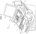
- FIG. 2 is a perspective view illustrating an example of an appearance of a registration apparatus 10 in the embodiment.
- the registration apparatus 10 is provided with a change machine 11e, a touch panel 11h, a combination keyboard 11j, which includes a keyboard 11ja and a touch panel 11jb, a printer 11k, a card reader/writer 11m, and a side display 11n.
- the registration apparatus 10 can be formed such that the touch panel 11h, the combination keyboard 11j, the printer 11k, and the side display 11n are detachably mounted on a housing or casing. Therefore, the touch panel 11h, the combination keyboard 11j, the printer 11k, and the display 11n may be selected and mounted according to what is considered suitable for use at a particular shop or retail location. In addition, some mounted components may be optional depending on the shop or retail location.
- the combination keyboard 11j has a form in which the keyboard 11ja and the touch panel 11jb are provided together; however, in other examples, a keyboard on which only keys are provided rather than inclusion of the touch panel 11jb, can be adopted. Also, a format in which input operations of the employee 2 are provided only from the touch panel 11h without the mounting or inclusion of the combination keyboard 11j is possible. In the example, it is assumed that the combination keyboard 11j (provided with the keyboard 11ja and the touch panel 11jb) illustrated in FIG. 3 is provided.
- the side display 11n is used as a customer viewing panel for providing information to the customer and it is possible to select and mount any one of a plurality of possible units having different screen sizes.
- a touch panel may be mounted instead of the side display 11n so as to receive an input operation from the customer.
- FIG. 4 is a block diagram illustrating a configuration of a registration apparatus 10A and an accounting apparatus 12A1 in an embodiment.
- the registration apparatus 10B has the same configuration as that of the registration apparatus 10 and a detailed description thereof will be omitted.
- the accounting apparatuses 12A2, 12B1, and 12B2 each have the same configuration as that of the accounting apparatus 12A1 and a detailed description thereof will be omitted.
- the registration apparatus 10A is equipped with a computer and includes a processor 11a, such as a central processing unit (CPU) or the like, a read-only memory (ROM) 11b, a random-access memory (RAM) 11c, a storage unit 11d, the change machine 11e, a communication unit 11f, a scanner 11g, the touch panel 11h, the combination keyboard 11j (keyboard 11ja and touch panel 11jb), the printer 11k, the card reader and writer 11m, and the display 11n.
- a processor 11a such as a central processing unit (CPU) or the like, a read-only memory (ROM) 11b, a random-access memory (RAM) 11c, a storage unit 11d, the change machine 11e, a communication unit 11f, a scanner 11g, the touch panel 11h, the combination keyboard 11j (keyboard 11ja and touch panel 11jb), the printer 11k, the card reader and writer 11m, and the display 11n.
- a processor 11a such as a central processing unit
- the processor 11a is an integrated circuit or the like for controlling each structural sub-unit to realize disclosed functional aspects of a registration apparatus 10 based on an operating system, middleware, and/or an application program stored in the ROM 11b or the RAM 11c.
- the ROM 11b and the RAM 11c store various programs executed by the processor 11a as well as data to be referred to when the processor 11a performs various processes.
- a registered commodity table in which information about a commodity being purchased by a customer is recorded when the process of registering the commodity is executed.
- the program executed by the processor 11a includes a control program for executing a process of inputting information (commodity code or the like) through the scanner 11g, a process of generating transaction information used for a settlement process according to information in the registered commodity table, a settlement process based on the transaction information, or the like.
- the program executed by the processor 11a further includes a display control method for displaying a screen indicating a current processing status of the settlement process executed in the accounting apparatus 12.
- a processor 11a executes a display control method to receive data indicating a current processing status in the various processing stages included in the settlement process from the accounting apparatus 12; display a state transition image indicating the processing stages; change a display format according to the current processing status; and to receive state data indicating a remaining amount of a banknote or coin in the change machine of the accounting apparatus 12, or a remaining amount of a paper in the printer provided in the accounting apparatus 12.
- the storage unit 11d stores data used by the processor 11a for performing various processes and data generated by the processor 11a.
- the storage unit 11d for example, an electronic erasable programmable read only memory (EEPROM), a hard disk drive (HDD), a solid state drive (SSD), or the like can be used.
- EEPROM electronic erasable programmable read only memory
- HDD hard disk drive
- SSD solid state drive
- the change machine 11e is a device that receives deposits and payments or the like, receives coins and banknotes from the employee 2, and dispenses coins and banknote as a change as necessary.
- the communication unit 11f performs communication with the registration apparatus 10B, the plurality of the accounting apparatuses 12, a server 13 via, for example, a local area network (LAN) 14.
- LAN local area network
- the scanner 11g reads information for the commodity by, for example, optical scanning and inputs a commodity code unique to the commodity.
- the scanner 11g may be a fixed type or a hand-held barcode-type code scanner or alternatively may identify the commodity by using an image recognition technique on a captured image of the commodity.
- one type may be provided or a plurality of types may be provided.
- the touch panel 11h includes a display device and a touch sensor.
- the display device displays an arbitrary screen, such as a Graphical User Interface (GUI) screen.
- GUI Graphical User Interface
- the display device displays a registration screen, such as commodity list screen, including a list of the transaction information, such as commodity name, amount of money, or the like, relating to a commodity registered as part of the sales transaction, a subtotal amount, various menus, and a button for inputting a command, and the like.
- a well-known device such as a color Liquid Crystal Display (LCD) can be used.
- the touch sensor is disposed to overlap a display surface of the display device. The touch sensor detects a touched position on the display surface of the display device and sends position information to the processor 11a.
- a well-known device can be used.
- the combination keyboard 11j is a device by which an input operation can be performed by the employee and includes, for example, the keyboard 11ja and the touch panel 11jb in which a plurality of keys, to which specific functions have been assigned individually, are arranged.
- the touch panel 11jb has the same configuration as that of the touch panel 11h.
- the touch panel 11jb displays supplementary information that does not need to be displayed at all times, special sale information, a message from a store manager, or the like to be primarily shared to the employees 2 in the store, or the like.
- the printer 11k is, for example, a thermal printer, a dot impact printer, or the like, and issues a transaction receipt including transaction content such as a commodity name, a unit price, or a total price is printed as various character strings, images, code patterns (e.g., barcodes, other two-dimensional codes, and the like.
- transaction content such as a commodity name, a unit price, or a total price is printed as various character strings, images, code patterns (e.g., barcodes, other two-dimensional codes, and the like.
- the card reader/writer 11m reads data recorded on a card and writes data to the card.
- a card includes various card types available for recording information relating to the settlement process, such as a membership card and a reward points card, in addition to a payment settlement card such as a credit card, a debit card, an electronic money card, or a prepaid card.
- the card reader/writer 11m may be any of a magnetic type, a contact type, and a non-contact type, or may include a plurality of types of these devices.
- the side display 11n can be a well-known device such as a color LCD panel.
- the accounting apparatus 12A1 is equipped with a computer function and includes a processor 12a, such as a central processor or the like, a read-only memory (ROM) 12b, a random-access memory (RAM) 12c, a storage unit 12d, a change machine 12e, a communication unit 12j, a scanner 12f, a touch panel 12g, a printer 12h, and a card reader and writer 12i.
- a processor 12a such as a central processor or the like
- ROM read-only memory
- RAM random-access memory
- the processor 12a executes a settlement process based on the transaction information generated by the registration process of the registration apparatus 10A based on a settlement process program stored in the ROM 12b or the RAM 12c. In the settlement process, data indicating the current processing stage is transmitted to the registration apparatus 10A.
- the processor 12a transmits state data indicating inventory data to the accounting apparatus 12A1.
- the inventory data indicates the remaining amount of banknotes and/or coins in the change machine 12e or a remaining amount of paper in the printer 12h.
- the change machine 12e can detect the current inventory of the stored banknotes and coins.
- the change machine 12e is provided with, for example, a banknote storage unit and a coin storage unit.
- the banknote storage unit includes a banknote storage box for each of denominations, detects when a banknote is inserted into or discharged from each banknote storage box by a sensor, and counts the number of the banknotes stored in the banknote storage box for each of the denomination.
- the coin storage unit includes a coin storage box for each of available denomination, detects when a coin is inserted into each coin storage box by a sensor, and counts the number of coins stored in each coin storage box.
- the change machine 12e can transmit its inventory data to the processor 12a at a predetermined transmission timing.
- the inventory data of the coin-roll indicates, for example, an inventory level of each of a plurality of coin denominations.
- the printer 12h a roll of paper is stored and as a necessary the paper is unrolled for printing a sales transaction receipt, then cut and discharged.
- the printer 12h is provided with a capability of detecting the remaining amount of paper on the roll or otherwise provided.
- the printer 12h is provided with a remaining amount sensor that detects that the paper has reached a predetermined remaining amount (e.g., a near-empty state) and can transmit the remaining amount data as detected by the remaining amount sensor to the processor 12a.
- a predetermined remaining amount e.g., a near-empty state
- the server 13 is a store server that manages the entire checkout system.
- the server 13 includes, for example, a processor, a ROM, a RAM, a storage unit, a communication unit, a display, a keyboard, and a printer. Similar to the accounting apparatus 12A1, the processor of the server 13 can be configured to realize functions of a receiving unit, a display unit, a change unit, a state data receiving unit by executing a stored display control method.
- the server 13 receives data indicating the current processing status from the accounting apparatus 12 through the LAN 14 and can display a state transition image indicating the processing status of the accounting apparatus 12 based on the data.
- a control process is started based on a control program stored in the ROM 11b or the storage unit 11d by the processor 11a.
- the processor 11a clears the registered commodity table stored in the RAM 11c and displays a registration screen on the touch panel 11h.
- the registration screen is provided to display information of the commodity registered in the registered commodity table or the like and is a screen for allowing the employee 2 to confirm an execution status of the registration process.
- the processor 11a When the processor 11a displays the state transition image indicating the processing status of the accounting apparatuses 12A and 12B on the touch panel 11jb, the processor 11a begins a state image display process based on the display control method stored in the ROM 11b or the storage unit 11d. When the processor 11a starts the state image display process, the processor 11a displays the state transition image on the touch panel 11jb. When the state transition image is not being displayed on the touch panel 11jb, the processor 11a displays supplementary information that does not need to be displayed at all times, such as special sale information, a message from a store manager, or the like, for the employees 2 in the store as necessary.
- the employee 2 instructs the display of the state transition image by a predetermined input operation, such as pressing of a button or keystrokes, with respect to the registration apparatus 10A.
- the processor 11a executes the state image display process according to the input operation by the employee 2 and displays the state transition image on the touch panel 11jb.
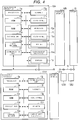
- FIG. 5 is a view illustrating an example of a state transition image SC displayed on the touch panel 11jb in the embodiment.
- the state transition image SC illustrated in FIG. 5 includes a first state transition image SC1, indicating the processing status of the accounting apparatus 12A1, and a second state transition image SC2, indicating the processing status of the accounting apparatus 12A2.
- the first state transition image SC1 and the second state transition image SC2 corresponding to the plurality of the accounting apparatuses 12A1 and 12A2 are displayed on one screen, but in other examples each of the first state transition image SC1 and the second state transition image SC2 may be displayed on a different screen.
- the processor 11a switches the first state transition image SC1 and the second state transition image SC2 to an individually displaying screen, for example, according to a predetermined operation of the employee 2.
- the state transition image corresponding to the accounting apparatuses 12A1 and 12A2 disposed in the vicinity of the registration apparatus 10A but also the state transition image corresponding to the accounting apparatuses 12B1 and 12B2 disposed in the vicinity of the other registration apparatus 10B may be displayed. Since the touch panel 11jb is provided independently of the touch panel 11h in this example, the registration screen is not hidden by the displaying of the state transition image so it does not hinder the registration process or the like.
- the first state transition image SC1 illustrated in FIG. 5 includes a state image 41-1 for displaying the present processing stage of the accounting apparatus 12A1, an inventory display image 42-1 for displaying the present inventory of the banknotes and coins stored in the change machine 12e of the accounting apparatus 12A1, and a remaining amount displaying image 43-1 for displaying the remaining amount of the receipt paper in the printer 12h of the accounting apparatus 12A1.
- the state image 41-1 indicates the current stage in the processing by reference to operation state transitions from among the plurality of processing stages, based on data indicating the current processing status that has been received from the accounting apparatus 12A1.
- the plurality of the processing stages executed by the accounting apparatus 12A1 includes, for example, a case where there are five possible stages: “standby”, “operation start”, “before settlement”, “change payment”, and "receipt”.
- each of the plurality of the processing stages is displayed by a symbol or graphic region and letters within the symbol or graphic region.
- any other graphic display form such as still images, moving images, or only words or letters may be adopted.
- the possible processing stages of the accounting apparatus 12A1 is not limited to the above description.
- the inventory display image 42-1 and the remaining amount displaying image 43-1 are displayed based on the state data indicating the status of the change machine 12e and the printer 12h received from the accounting apparatus 12A1.
- the inventory display image 42-1 represents the inventory of various denominations of the banknote and coins stored in the change machine 12e, for example, by the number of units (e.g., sheets).
- a near empty display "N" 42N is added next to each of the denominations having less than the preset number. If the inventory exceeds a preset maximum number above which the change machine 12e is not capable of storing (or some otherwise arbitrary maximum value), a full display "F" (“F" 42F indicated in the second state transition image SC2) is added next to each of the denominations exceeding the preset maximum number.
- the remaining amount displaying image 43-1 represents the remaining amount of the receipt paper stored in the printer 12h.
- “normal” in which the remaining amount is deemed sufficient for normal operations
- “near end” in which the remaining amount is equal to or less than some preset value
- “no remaining amount” in which there is no receipt paper left can be displayed.
- the second state transition image SC2 illustrated in FIG. 5 includes a state image 41-2 for displaying the processing stage of the accounting apparatus 12A2, an inventory display image 42-2 for displaying the inventory of the banknote and coins stored in the change machine 12e of the accounting apparatus 12A2, and a remaining amount display image 43-2 for displaying the remaining amount of the receipt paper stored in the printer of the accounting apparatus 12A2.
- the second state transition image SC2 is displayed in the same manner as the first state transition image SC1 and a detailed description thereof will be omitted.
- FIG. 6 is a flowchart for explaining a process for displaying the state transition image SC, including an inventory display image and a remaining amount display image, of the registration apparatus 10A.
- the display of the inventory display image 42-1 and the remaining amount displaying image 43-1 of the first state transition image SC1 corresponding to the accounting apparatus 12A1 is described as an example.
- the second state transition image SC2, including the inventory display image 42-2 and the remaining amount display image 43-2, corresponding to the accounting apparatus 12A2 also executes substantially the same process and the description thereof will be omitted.
- the processor 11a receives the inventory data of the change machine 12e from the accounting apparatus 12A1.
- the inventory data includes data indicating banknote and coin inventory levels for each of the various denominations.
- a request for transmitting the inventory data of the change machine 12e may be issued from the registration apparatus 10A at a predetermined time, or the processor 12a of the accounting apparatus 12A1 acquires the inventory data from the change machine 12e at a predetermined time interval and may transmit the acquired inventory data to the registration apparatus 10A.
- the accounting apparatus 12A1 can acquire the inventory data from the change machine 12e and transmits the inventory data to the registration apparatus 10A.
- the processor 11a When the processor 11a receives the inventory data of the change machine 12e from the accounting apparatus 12A1 (Act 2), the display content of the inventory display image 42-1 of the state transition image SC displayed in the touch panel 11jb is updated (Act 3).
- the processor 11a adds a display (near empty display "N", or full display "F") indicating the warning.
- a display near empty display "N", or full display "F”
- the display form is changed to a form different from ordinary, for example, a background color is changed to a color indicating a warning so that the employee 2 can easily recognize the warning display.
- the processor 11a When it is time to receive the remaining amount data of the printer 11k from the accounting apparatus 12A1 (Act 6, Yes), the processor 11a receives the remaining amount data of the printer 11k transmitted from the accounting apparatus 12A1.
- the remaining amount data indicates the remaining amount of the receipt paper stored in the printer 11k and, for example, any of "normal” in which the remaining amount is deemed sufficient, “near end” in which the remaining amount is equal to or less than a preset value, and "no remaining amount” in which there is no receipt paper may be indicated.
- a request for transmitting the remaining amount data of the printer 11k with respect to the accounting apparatus 12A1 may be issued from the registration apparatus 10A for a predetermined time, or the processor 12a of the accounting apparatus 12A1 acquires the remaining amount data from the printer 11k for predetermined time intervals and may transmit the remaining amount data to the registration apparatus 10A. Also, when there is a preset status change condition in the remaining amount in the printer 11k, such as a decrease in remaining amount below a preset threshold value, the accounting apparatus 12A1 can acquire the remaining amount data from the printer 11k and transmit the remaining amount data to the registration apparatus 10A.
- a notification (e.g., a warning) can be provided to the employee 2 when the receipt paper of the printer 12h is in the "near end” or the “no remaining amount” conditions, and the accounting apparatus 12A1 may receive the remaining amount data only when the receipt paper is in the "near end” or the "no remaining amount” state.
- the processor 11a determines whether or not the remaining amount data indicates that a warning display of the "near end" or the "no remaining amount” is required.
- the processor 11a changes the display of the remaining amount displaying image 43-1 to the "near end" or the "no remaining amount” as indicated by the remaining amount data.
- the warning display is performed, the display form is changed to a form different from ordinary, for example, the background color is changed to the color indicating a warning, so that the employee 2 can easily recognize the warning display.
- the timing (Act 1) for receiving the inventory data of the change machine 12e from the accounting apparatus 12A1 and the timing (Act 6) for receiving the remaining amount data of the printer 12h may be the same, or may be different timing from each other.
- the state transition image is displayed on the touch panel 11jb, but may also or instead be displayed in the touch panel 11h.
- the state transition image is displayed on the touch panel 11h according to the instruction by the input operation of the employee 2.
- the employee 2 can simultaneously monitor the state of the change machine 12e and the printer 12h from the first state transition image SC1. Therefore, it is unnecessary to individually respond to a status requiring replenishment work in each of the change machine 12e and the printer 12h, and it is possible to efficiently execute the replenishment work with respect to the change machine 12e and the printer 12h.
- the inventory display image 42-2 and the remaining amount display image 43-2 of the second state transition image SC2 it is possible to display the inventory of the banknote and coins stored in the change machine and the remaining amount of the receipt paper stored in the printer of the accounting apparatus 12A2. Therefore, it is possible to monitor the inventory and the remaining amount of the receipt paper of a plurality of the accounting apparatuses 12A1 and 12A2 at the same time, and to improve the efficiency of the replenishment operation.
- FIGS. 7 and 8 are flowcharts for explaining a process for displaying the state transition image SC of the registration apparatus 10A in the embodiment.
- the display of the state image 41-1 of the first state transition image SC1 corresponding to the accounting apparatus 12A1 is described as an example.
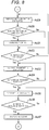
- FIG. 9 is a flowchart for explaining a process of the accounting apparatus 12A1.
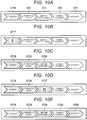
- FIGs. 10A to 10E are views illustrating an example of a display form of the state image 41-1.
- the second state transition image SC2 and the state image 41-2 on the second state transition image SC2 corresponding to the accounting apparatus 12A2 executes substantially the same process and a detailed description thereof will be omitted.
- the processor 11a When it is detected that a commodity code attached to a commodity has been read by the scanner 11g, the processor 11a registers or updates the information of the commodity corresponding to the commodity code in the registered commodity table. The processor 11a updates the information in the registration screen according to the content of the updated registered commodity table. Thereafter, as described above, the processor 11a sequentially adds the information of the commodity according to an acquired commodity code to the registered commodity table whenever the employee 2 performs an operation to read a commodity code with the scanner 11g.
- the processor 11a After at least one commodity is registered, when it is detected that a subtotal button is pressed (Act 21, Yes), the processor 11a generates the transaction information for the settlement process based on the content in the registered commodity table.
- the transaction information includes information such as the list of the registered commodities and the total number and the total price of the purchased commodities.
- the processor 11a transmits the transaction information to, for example, the accounting apparatus 12A1 which executes the settlement process based on the transaction information.
- the processor 11a starts measurement of a "standby" time from the transmission of the transaction information until an operation is started in the accounting apparatus 12A1 (Act 22).
- the processor 11a changes the display form of the figure corresponding to the processing stage of "standby" of the state image 41-1 (Act 23). That is, it displays that the processing stage in the accounting apparatus 12A1 is in the "standby" state.
- As the change of the display form it is made into a form different from ordinary; for example, the display is changed to a specific color display, or the like.
- FIG. 10A illustrates an operation in which a figure ST1 corresponding to the processing stage of "standby" of the state image 41-1 is changed to the display form of a figure ST1B indicating that the figure ST1 reaches the processing stage of the "standby".
- the figure ST1B has the display form different from figures ST2, ST3, ST4, and ST5 respectively corresponding to other processing stages of "operation start", “before settlement”, “change payment”, and "receipt". Therefore, it is possible to see that the processing stage of the accounting apparatus 12A1 is in "standby” by referring to the display of the state image 41-1.
- the processor 12a of the accounting apparatus 12A1 when the processor 12a of the accounting apparatus 12A1 receives the transaction information from the registration apparatus 10A, the processor 12a displays a standby screen for receiving an operation of a shopper 4 on the touch panel 12g (Act 41).
- the standby screen is a screen provided with selection buttons for selecting a payment method, such as cash or credit payment.
- the processor 11a of the registration apparatus 10A measures a time until an operation is started by the shopper 4, that is a time until an operation start notification is received, from the accounting apparatus 12A1 (Acts 22 to 26).
- the processor 11a determines whether or not the measured time elapsed from start of the "standby" time exceeds a preset value (Act 24).
- the processor 11a When it is determined that a preset time in "standby” state has elapsed (Act 24, Yes), the processor 11a performs a warning display indicating that the "standby" time has exceeded the preset time within the state image 41-1.
- the "standby" time two time periods are set in advance.
- a first "standby" time for example, an estimated time until an operation is actually started by the shopper 4 from reception of the transaction information until the settlement process is performed on the accounting apparatus 12A1 is set. That is, the estimated time (for example, 20 seconds) required for an ordinary/average shopper 4 to begin the settlement process is provided as preset value. Therefore, when the settlement operation has not started even though the first "standby" time has elapsed, it is possible to determine that the employee 2 needs to help or otherwise deal with the shopper 4 due to possible occurrence of a difficulty or the like.
- a time less than the first "standby” time is set. That is, a display start time (for example, 10 seconds) for notifying the employee 2 before the full first "standby" time has been exceeded.
- the processor 11a changes to the display form that displays a countdown number or the like indicating a time until the first "standby" time will have been exceeded as a warning display (Act 25).
- FIG. 10B illustrates an example of a figure ST1T displaying a remaining time (8 seconds) until the first "standby" time is reached in the figure ST1 corresponding to the processing stage of the "standby" of the state image 41-1.
- the processor 11a changes a number indicating the remaining time displayed in the figure ST1T with the time elapsed.
- the display of the figure ST1 illustrated in FIG. 10A is changed to the figure ST1T so that the employee 2 can monitor that the shopper 4 does not begin immediately and can continuously recognize the remaining time up to the estimated time at which the operation would started if all was normal and ordinary. Therefore, the employee 2 can begin to pay attention to the shopper 4 who does not start the settlement operation, and can begin to prepare to deal with this shopper 4.
- the processor 11a changes the figure ST1 to the warning display indicating that the first "standby" time has been met as a warning display (Act 25). For example, since there is a possibility that the shopper 4 cannot start the settlement operation due to occurrence of trouble or the like, in order to urgently prompt action to deal with the potential trouble, the figure ST1 is changed to a display form which can be particularly recognized by the employee 2, for example, the figure ST1 is blink-displayed in red. Therefore, the employee 2 can immediately respond to the shopper 4 having trouble or the like.
- an operation start notification is transmitted to the registration apparatus 10A (Act 43).
- the processor 11a of the registration apparatus 10A receives the operation start notification from the accounting apparatus 12A1 (Act 26, Yes)
- the processor 11a changes the display form of a figure ST2 corresponding to the processing stage of the "operation start” of the state image 41-1, and displays so as to indicate that the processing stage in the accounting apparatus 12A1 is in the "operation start” state (Act 27).
- the warning display is performed for the figure ST1, similar to the figure ST2, the figure ST1 is changed to a display form indicating that it reaches the ordinary processing stage.
- the processor 11a starts measurement of the "before settlement” time until the settlement operation is performed in the accounting apparatus 12A1 from the start of the operation (Act 28).
- the processor 11a changes the display form of a figure ST3 corresponding to the processing stage of the "before settlement” of the state image 41-1, and displays so as to indicate that the processing stage in the accounting apparatus 12A1 is in the "before settlement” state (Act 29).
- FIG. 10C illustrates a state where the display form up to the figure ST3 corresponding to the processing stage of the "before settlement” of the state image 41-1 is changed.
- figures ST1B, ST2B, and ST3B which are changed to the display forms respectively indicating that it reaches the processing stages of "standby”, “operation start”, and "before settlement", to the processing stage of the "before settlement", are displayed.
- the processor 11a of the registration apparatus 10A determines whether or not the measured time exceeds the preset "before settlement” time while measuring the time from the start of the operation by the shopper 4 to the settlement operation in the accounting apparatus 12A1 (Act 30).
- the processor 11a When it is determined that the "standby” time has elapsed (Act 30, Yes), the processor 11a performs the warning display indicating that the "before settlement” time has elapsed in the state image 41-1.
- the "before settlement" time similar to the "standby” time, two time periods are set in advance.
- the first "before settlement” time for example, an estimated time until the completion of the payment operation after the accounting apparatus 12A1 receives of the transaction information is set. That is, the estimated time (for example, 40 seconds) required for the settlement operation to be normally completed if it is the shopper 4 is ordinary or average is set. Therefore, when the settlement operation is not completed even though the first "before settlement" time has elapsed, it is possible to determine that the employee 2 needs to deal with the shopper 4 due to occurrence of a trouble or the like.
- the estimated time for example, 40 seconds
- a time shorter than the first "before settlement” time is set. That is, a display start time (for example, 30 seconds) is set for notifying the employee 2 before the first "before settlement” time is reached.
- the processor 11a changes to the display form that displays a countdown number indicating a time until the first "before settlement” time is reached as the warning display (Act 31).
- FIG. 10D illustrates an example of a figure ST3T displaying a remaining time (25 seconds) until it reaches the first "before settlement” time in the figure ST3B corresponding to the processing stage of the "before settlement” of the state image 41-1.
- the processor 11a changes a number indicating the remaining time displayed in the figure ST3T with the time elapsed.
- the display of the figure ST3B illustrated in FIG. 10C is changed to the figure ST3T so that the employee 2 can see that the shopper 4 has not yet completed the settlement operation and can continuously recognize the remaining time up to the estimated time at which the settlement operation is completed if it is ordinary. Therefore, the employee 2 can pay attention to the shopper 4 who cannot complete the settlement operation (including, for example, a deposit operation, an credit card inserting operation, or the like), and can prepare to deal with the shopper 4.
- the processor 11a changes the figure ST3 to the form of the warning display indicating it reaches the first "before settlement” time as the warning display (Act 31). For example, since there is a possibility that the shopper 4 may not able to complete the settlement operation because a method of the settlement operation is unknown, in order to urgently prompt action to deal with this, the figure ST3 is changed to a display form which can be particularly recognized by the employee 2, for example, the figure ST3 is blink-displayed in red. Therefore, the employee 2 can immediately respond to the shopper 4.
- the processor 12a of the accounting apparatus 12A1 transmits the settlement notification to the registration apparatus 10A (Act 46).
- the processor 11a of the registration apparatus 10A receives the settlement notification from the accounting apparatus 12A1 (Act 32, Yes)
- the processor 11a changes the display form of a figure ST4 corresponding to the processing stage of the "change payment" of the state image 41-1, and displays so as to indicate that the processing stage in the accounting apparatus 12A1 is in the "change payment” state (Act 33).
- the warning display is performed for the figure ST3, similar to the figure ST4, the figure ST3 is changed to a display form indicating that it reaches the ordinary processing stage.
- the processor 12a of the accounting apparatus 12A1 transmits the change payment notification to the registration apparatus 10A (Act 48).
- the processor 11a of the registration apparatus 10A changes the display form of the figure ST5 corresponding to the processing stage of the "receipt" of the state image 41-1 and displays information so as to indicate that the processing stage in the accounting apparatus 12A1 has reached the "receipt" issuance (Act 35).
- FIG. 10E illustrates a state of changing the display form to the figure ST5 corresponding to the processing stage of the "receipt" of the state image 41-1.
- the figures ST1B to ST5B which are changed to the display forms indicating that it reaches all the processing stages to the processing stage of the "receipt", are displayed.
- the processor 12a of the accounting apparatus 12A1 issues the receipt by the printer 12h after the change payment is completed (Act 49) and when the receipt issuance is completed (Act 50, Yes), transmits the receipt issuance notification to the registration apparatus 10A (Act 51).
- the processor 11a of the registration apparatus 10A clears the display of the state image 41-1 and returns the procedure to the initial state (Act 37). That is, it changes to the display form indicating that the settlement process is completed in the accounting apparatus 12A1.
- the entire process executed by the accounting apparatus 12A1 is divided into a plurality of stages and is displayed as the state image 41-1 of the first state transition image SC1, and the display of the processing stage according to the processing status can be changed. That is, in the state image 41-1, the processing stage reached by the state transition is displayed in accordance with the transition of the process in the accounting apparatus 12A1 so that it is possible to grasp intuitively and easily the current processing stage in the entire process.
- the process described in the above-described example embodiment can be provided to various apparatuses by being written in, for example, a recording medium such as a magnetic disk (a flexible disk, a hard disk, or the like), an optical disk (a CD-ROM, a DVD or the like), and a semiconductor memory as a program that can be executed by a computer. Furthermore, the program can be transmitted via a communication network and can thereby be provided to various apparatuses.
- a computer reads a program recorded on a recording medium or receives a program via a communication network, and the operation and configuration of such a computer is controlled and/or changed by the program to execute the above-described processing.
Landscapes
- Business, Economics & Management (AREA)
- Accounting & Taxation (AREA)
- Physics & Mathematics (AREA)
- General Physics & Mathematics (AREA)
- Finance (AREA)
- Strategic Management (AREA)
- General Business, Economics & Management (AREA)
- Engineering & Computer Science (AREA)
- Theoretical Computer Science (AREA)
- Cash Registers Or Receiving Machines (AREA)
Abstract
A register system includes a display screen and a communication interface connectable to a settlement processing apparatus at which a payment process associated with a commodity sales transaction can be performed. A processor is configured to receive data from the settlement processing apparatus indicating a current stage of the payment process as one of a plurality of predetermined possible stages in the payment process. The processor controls the display screen to display a settlement process state image for indicating the current stage of the payment process. The settlement process state image includes image regions corresponding to each of the predetermined possible stages in the payment process. The processor changes a display format of an image region corresponding to the current stage of the payment process according to the received data from the settlement processing apparatus.
Description
- The present invention relates to the field of a retail transaction accounting system in general, and embodiments described herein relate in particular to a register system.
- In a retail transaction accounting system, such as a cash register or a checkout system, used in a supermarket or the like, a sales processing apparatus called a Point of Sale (POS) terminal is widely used. In a sales processing apparatus, registration of a commodity being purchased and the payment/settlement process are executed in accordance with an operation of a store clerk or the like.
- However, in recent years, a checkout system, sometimes referred to as semi-self-service checkout system, have been developed in which a commodity registration apparatus operated by a store employee and accounting settlement apparatus operated by a customer based on the sales transaction information generated by the registration apparatus. In the semi-self service checkout system, it remains necessary for the employee operating the registration apparatus to also manage the settlement apparatus and to respond to customer actions entered using the settlement apparatus. Therefore, the system in the related art transmits information indicating an operation state of the settlement apparatus, such as completion of the settlement processing on the settlement apparatus by the customer to the registration apparatus, and then notifying the employee of the state by displaying a message or the like on the registration apparatus.
- When the notification of operation state for the employee is generated in the settlement apparatus, the state of the settlement apparatus is displayed on the settlement apparatus when the registration apparatus is notified. Therefore, it is difficult to notify an operation state other than a predetermined operation state such as processing completion. That is, it is difficult for the store clerk to grasp intuitively and easily determine at which particular processing stage in the entire processing the customer is presently performing on the settlement apparatus. For example, when the processing by the customer for the settlement process appears long, the employee cannot easily determined the time has actually elapsed and has to arbitrarily judge the present state of the customer processing.
- To solve such problem, there is provided a register system comprising: a display screen; a communication interface connectable to a settlement processing apparatus at which a payment process associated with a commodity sales transaction can be performed; and a processor configured to: receive data via the communication interface from the settlement processing apparatus indicating a current stage of the payment process on the settlement processing apparatus as one of a plurality of predetermined possible stages in the payment process; control the display screen to display a settlement process state image for indicating the current stage of the payment process on the settlement processing apparatus, the settlement process state image including image regions corresponding to each of the predetermined possible stages in the payment process; and change a display format on the display screen of an image region corresponding to one of the predetermined possible stages in the payment process matching the current stage of the payment process according to the received data from the settlement processing apparatus.
- Preferably, the system further comprises: a commodity scanner for registering items in the commodity sales transaction; and a clerk data input unit including a keyboard and a touch panel, the clerk data input unit being configured to permit a sales clerk to input information related to the commodity sales transaction.
- Preferably still, the display format on the display screen of the image region is a display color.
- Preferably yet, the processor is further configured to track an elapsed time from a beginning of at least one of the predetermined possible stages in the payment process according to data received from the settlement processing apparatus and to display the elapsed time on the display screen.
- Suitably, the processor is further configured to control the display screen to display a warning image when the elapsed time exceeds a threshold value.
- Suitably still, the communication interface is connected to a plurality of settlement processing apparatuses, the processor is configured to receive data, via the communication interface, from each settlement processing apparatus in the plurality, and the processor is configured to control the display screen to display a settlement process state image corresponding to each settlement processing apparatus.
- Suitably yet, the processor is further configured to: receive inventory state data from the settlement processing apparatus, the inventory state data indicating at least one of a remaining amount of a banknote denomination within the settlement processing apparatus, a remaining amount of a coin denomination within the settlement processing apparatus, and a remaining amount of paper in a receipt printer of the settlement processing apparatus, and control the display screen to display a screen image according to the inventory state data along with the settlement process state image for the settlement processing apparatus.
- The invention also relates to a retail store checkout system, comprising: a sales registration apparatus including a commodity scanner for registering items in a sales transaction, a display screen for displaying information associated with the sales transaction to sales clerk, and a communication interface; and a plurality of settlement processing apparatuses connected to the sales registration apparatus via the communication interface, each settlement processing apparatus being configured to receive sales transaction data from the sales registration apparatus and process payments from a customer for settlement of the sales transaction, wherein the sales registration apparatus is configured to: receive data via the communication interface from each settlement processing apparatus, the data indicating a current stage of the payment process on the settlement processing apparatus as one of a plurality of predetermined possible stages in the payment process; control the display screen to display a settlement process state image for each settlement processing apparatus, the settlement process state image for each settlement processing apparatus indicating the current stage of the payment process on the respective settlement processing apparatus, each settlement process state image including image regions corresponding to each of the predetermined possible stages in the payment process; and change a display format on the display screen of an image region corresponding to one of the predetermined possible stages in the payment process matching the current stage of the payment process according to the received data from each settlement processing apparatus.
- Preferably, the display format on the screen of the image region is a display color.
- Preferably still, the sales registration apparatus is further configured to track an elapsed time from a beginning of at least one of the predetermined possible stages in the payment process according to data received from the settlement processing apparatus and to display the elapsed time on the display screen.
- Preferably yet, the sales registration apparatus is further configured to control the display screen to display a warning image when the elapsed time exceeds a threshold value.
- Suitably, the sales registration apparatus is further configured to: receive inventory state data from each settlement processing apparatus, the inventory state data indicating at least one of a remaining amount of a banknote denomination within the settlement processing apparatus, a remaining amount of a coin denomination within the settlement processing apparatus, and a remaining amount of paper in a receipt printer of the settlement processing apparatus, and control the display screen to display a screen image according to the inventory state data along with the settlement process state image for each settlement processing apparatus.
- The invention further relate to a register machine for a retail store checkout system that includes a plurality of customer-operated settlement processing apparatuses, the sales registration apparatus comprising: a commodity scanner for registering items in a commodity sales transaction; a clerk data input unit including a keyboard and a touch panel, the clerk data input unit being configured to permit a sales clerk to input information related to the commodity sales transaction; a display screen for displaying information to the sales clerk that is associated with the commodity sales transaction; a communication interface connected to a plurality of settlement processing apparatuses at which a payment process associated with the commodity sales transaction can be performed by a customer; and a processor configured to: receive data, via the communication interface, from each settlement processing apparatus, the data indicating a current stage of the payment process on the settlement processing apparatus as one of a plurality of predetermined possible stages in the payment process; control the display screen to display a settlement process state image for indicating the current stage of the payment process on the settlement processing apparatus, the settlement process state image including image regions corresponding to each of the predetermined possible stages in the payment process; and change a display format on the display screen of an image region corresponding to one of the predetermined possible stages in the payment process matching the current stage of the payment process according to the received data from the settlement processing apparatus.
- Preferably, the display format on the display screen of the image region is a display color.
- Preferably still, the processor is further configured to track an elapsed time from a beginning of at least one of the predetermined possible stages in the payment process according to data received from the settlement processing apparatus and to display the elapsed time on the display screen.
- Preferably yet, the processor is further configured to control the display screen to display a warning image when the elapsed time exceeds a threshold value.
- Suitably, the processor is further configured to: receive inventory state data from each settlement processing apparatus, the inventory state data indicating at least one of a remaining amount of a banknote denomination within the settlement processing apparatus, a remaining amount of a coin denomination within the settlement processing apparatus, and a remaining amount of paper in a receipt printer of the settlement processing apparatus, and control the display screen to display a screen image according to the inventory state data along with the settlement process state image for the respective settlement processing apparatus.
- The invention also concerns a method for displaying a stage of a payment process on a settlement processing apparatus in a registration apparatus comprising steps of: detecting, by the registration apparatus, that a subtotal button on the settlement processing apparatus is pressed, transmitting, by the registration apparatus, transaction information to the settlement processing apparatus, starting, by the registration apparatus, a measurement of a standby time from the transmission of the transaction information until an operation is started in the settlement apparatus, and displaying a figure, on the registration apparatus, to display that the stage is in the standby state until the standby time exceed a preset value.
- The invention further concerns a recording medium storing a program causing a computer to execute the method.
- The above and other objects, features and advantages of the present invention will be made apparent from the following description of the preferred embodiments, given as non-limiting examples, with reference to the accompanying drawings, in which:
-
FIG. 1 is a plan view illustrating an arrangement of a registration apparatus and a plurality of the accounting apparatuses in a semi-self service checkout system of an embodiment. -
FIG. 2 is a perspective view illustrating an example of an appearance of the registration apparatus in the embodiment. -
FIG. 3 is a view illustrating an example of a combination keyboard in the embodiment. -
FIG. 4 is a block diagram illustrating a configuration of the registration apparatus and the accounting apparatus in the embodiment. -
FIG. 5 is a view illustrating an example of a state transition image displayed on a touch panel in the embodiment. -
FIG. 6 is a flowchart for explaining a process for displaying the state transition image of the registration apparatus in the embodiment. -
FIG. 7 is a flowchart of aspects of a process for displaying the state transition image of the registration apparatus in the embodiment. -
FIG. 8 is a flowchart of aspects of a process for displaying the state transition image of the registration apparatus in the embodiment. -
FIG. 9 is a flowchart of aspects of a process of the accounting apparatus in the embodiment. -
FIGs. 10A to 10E are views illustrating an example of a display form of a state image in the embodiment. - In general, according to an embodiment, a register system includes a display screen, a communication interface connectable to a settlement processing apparatus at which a payment process associated with a commodity sales transaction can be performed, and a processor. The processor is configured to receive data via the communication interface from the settlement processing apparatus indicating a current stage of the payment process on the settlement processing apparatus as one of a plurality of predetermined possible stages in the payment process, control the display screen to display a settlement process state image for indicating the current stage of the payment process on the settlement processing apparatus, the settlement process state image including image regions corresponding to each of the predetermined possible stages in the payment process, and change a display format on the display screen of an image region corresponding to one of the predetermined possible stages in the payment process matching the current stage of the payment process according to the received data from the settlement processing apparatus.
- Hereinafter, an example embodiment will be described with reference to the drawings. The checkout system in the example embodiment is installed in, for example, a shop or retail location such as a supermarket. In the following description, it is assumed that a semi-self service checkout system is used. That is, the checkout system uses customer actions/operations for aspects of the sales transaction registration/settlement. Here, the semi-self service checkout system is provided with a product registration apparatus, which executes a registration process in which an employee operates the product registration apparatus, and payment settlement apparatus, which executes a settlement process in which the customer primarily controls the settlement apparatus.
-
FIG. 1 is an overhead, plan view illustrating a semi-self service checkout system according to an embodiment.FIG. 1 depicts an arrangement of a plurality ofregistration apparatuses 10, in particular, aregistration apparatus 10A and aregistration apparatus 10B and a plurality of accounting apparatuses 12, in particular, accounting apparatuses 12A1, 12A2, 12B1, and 12B2. In some contexts, the accounting apparatuses 12 may be referred to as settlement processing apparatuses or customer operated settlement processing apparatuses. The checkout system illustrated inFIG. 1 is provided with tworegistration apparatuses registration apparatus 10A, are provided in the vicinity of theregistration apparatus 10A. Similarly, two accounting apparatuses 12B1 and 12B2, which execute a settlement process based on transaction information generated in theregistration apparatus 10B, are provided in the vicinity of theregistration apparatus 10B. - The
registration apparatus 10A receives a commodity code of a commodity being purchased by a shopper 4, such asshopper 4A-1, and generates the transaction information used for a settlement process in the accounting apparatus 12 based on the commodity code. The transaction information includes information on at least one commodity and an amount of money required to settle the sales transaction. Theregistration apparatus 10A is operated by an employee 2-1 who performs a commodity registration operation, and may be called a checker or a checkout clerk. Theregistration apparatus 10A may include functionality permitting the checker to perform the same-type settlement processing operations as any of the accounting apparatuses 12, if necessary. - The accounting apparatuses 12A1 and 12A2 receive transaction information generated by the
registration apparatus 10A and permits performance of the settlement processing based on the transaction information. The accounting apparatuses 12A1 and 12A2 are to be operated by certain shoppers 4 (e.g.,shopper 4A-2 andshopper 4A-3, respectively). InFIG. 1 , an example in which two accounting apparatuses 12A1 and 12A2 are provided is illustrated. However, in other examples, three or more accounting apparatuses 12 may be provided. - Similar to the
registration apparatus 10A, theregistration apparatus 10B registers a commodity being purchased by a shopper 4, in particular here, shopper4B-1 and generates transaction information. Theregistration apparatus 10B is operated by an employee 2-2, also referred to as a checker, checkout clerk, or a sales clerk. In general, theregistration apparatus 10B has functionality for performing the same settlement processing as might otherwise be carried out on the accounting apparatus 12 based on the transaction information. - The accounting apparatuses 12B1 and 12B2 receive the transaction information generated by the
registration apparatus 10B and perform the settlement processing based on the transaction information. In this example, the accounting apparatuses 12B1 and 12B2 are operated by theshopper 4B-2 and theshopper 4B-3, respectively. - The checkout system according to this disclosure is not limited to in the number of the
registration apparatuses 10 that might be provided at the retail location. Also, although for the transaction information generated by aparticular registration apparatus 10 is supplied ton an accounting apparatus 12 provided in the vicinity of theparticular registration apparatus 10, in other examples, the settlement process may be executed in the accounting apparatus 12 provided at distance from the particular registration apparatus. For example, the transaction information generated by theregistration apparatus 10A may be sent for settlement processing to the accounting apparatus 12B1 or the accounting apparatus 12B2. -
FIG. 2 is a perspective view illustrating an example of an appearance of aregistration apparatus 10 in the embodiment. - As illustrated in
FIG. 2 , theregistration apparatus 10 is provided with achange machine 11e, atouch panel 11h, acombination keyboard 11j, which includes a keyboard 11ja and a touch panel 11jb, aprinter 11k, a card reader/writer 11m, and aside display 11n. - The
registration apparatus 10 can be formed such that thetouch panel 11h, thecombination keyboard 11j, theprinter 11k, and theside display 11n are detachably mounted on a housing or casing. Therefore, thetouch panel 11h, thecombination keyboard 11j, theprinter 11k, and thedisplay 11n may be selected and mounted according to what is considered suitable for use at a particular shop or retail location. In addition, some mounted components may be optional depending on the shop or retail location. - For example, as illustrated in
FIGS. 2 and3 , thecombination keyboard 11j has a form in which the keyboard 11ja and the touch panel 11jb are provided together; however, in other examples, a keyboard on which only keys are provided rather than inclusion of the touch panel 11jb, can be adopted. Also, a format in which input operations of theemployee 2 are provided only from thetouch panel 11h without the mounting or inclusion of thecombination keyboard 11j is possible. In the example, it is assumed that thecombination keyboard 11j (provided with the keyboard 11ja and the touch panel 11jb) illustrated inFIG. 3 is provided. - Similarly, the
side display 11n is used as a customer viewing panel for providing information to the customer and it is possible to select and mount any one of a plurality of possible units having different screen sizes. Likewise, a touch panel may be mounted instead of theside display 11n so as to receive an input operation from the customer. -
FIG. 4 is a block diagram illustrating a configuration of aregistration apparatus 10A and an accounting apparatus 12A1 in an embodiment. In general, theregistration apparatus 10B has the same configuration as that of theregistration apparatus 10 and a detailed description thereof will be omitted. The accounting apparatuses 12A2, 12B1, and 12B2 each have the same configuration as that of the accounting apparatus 12A1 and a detailed description thereof will be omitted. - The
registration apparatus 10A is equipped with a computer and includes aprocessor 11a, such as a central processing unit (CPU) or the like, a read-only memory (ROM) 11b, a random-access memory (RAM) 11c, astorage unit 11d, thechange machine 11e, acommunication unit 11f, ascanner 11g, thetouch panel 11h, thecombination keyboard 11j (keyboard 11ja and touch panel 11jb), theprinter 11k, the card reader andwriter 11m, and thedisplay 11n. - The
processor 11a is an integrated circuit or the like for controlling each structural sub-unit to realize disclosed functional aspects of aregistration apparatus 10 based on an operating system, middleware, and/or an application program stored in theROM 11b or theRAM 11c. - The
ROM 11b and theRAM 11c store various programs executed by theprocessor 11a as well as data to be referred to when theprocessor 11a performs various processes. For example, in theRAM 11c, a registered commodity table in which information about a commodity being purchased by a customer is recorded when the process of registering the commodity is executed. - The program executed by the
processor 11a includes a control program for executing a process of inputting information (commodity code or the like) through thescanner 11g, a process of generating transaction information used for a settlement process according to information in the registered commodity table, a settlement process based on the transaction information, or the like. The program executed by theprocessor 11a further includes a display control method for displaying a screen indicating a current processing status of the settlement process executed in the accounting apparatus 12. Aprocessor 11a executes a display control method to receive data indicating a current processing status in the various processing stages included in the settlement process from the accounting apparatus 12; display a state transition image indicating the processing stages; change a display format according to the current processing status; and to receive state data indicating a remaining amount of a banknote or coin in the change machine of the accounting apparatus 12, or a remaining amount of a paper in the printer provided in the accounting apparatus 12. - The
storage unit 11d stores data used by theprocessor 11a for performing various processes and data generated by theprocessor 11a. As thestorage unit 11d, for example, an electronic erasable programmable read only memory (EEPROM), a hard disk drive (HDD), a solid state drive (SSD), or the like can be used. - The
change machine 11e is a device that receives deposits and payments or the like, receives coins and banknotes from theemployee 2, and dispenses coins and banknote as a change as necessary. - The
communication unit 11f performs communication with theregistration apparatus 10B, the plurality of the accounting apparatuses 12, aserver 13 via, for example, a local area network (LAN) 14. - The
scanner 11g reads information for the commodity by, for example, optical scanning and inputs a commodity code unique to the commodity. Thescanner 11g may be a fixed type or a hand-held barcode-type code scanner or alternatively may identify the commodity by using an image recognition technique on a captured image of the commodity. For thescanner 11g, one type may be provided or a plurality of types may be provided. - The
touch panel 11h includes a display device and a touch sensor. The display device displays an arbitrary screen, such as a Graphical User Interface (GUI) screen. For example, the display device displays a registration screen, such as commodity list screen, including a list of the transaction information, such as commodity name, amount of money, or the like, relating to a commodity registered as part of the sales transaction, a subtotal amount, various menus, and a button for inputting a command, and the like. As the display device, for example, a well-known device such as a color Liquid Crystal Display (LCD) can be used. The touch sensor is disposed to overlap a display surface of the display device. The touch sensor detects a touched position on the display surface of the display device and sends position information to theprocessor 11a. As the touch sensor, a well-known device can be used. - The
combination keyboard 11j is a device by which an input operation can be performed by the employee and includes, for example, the keyboard 11ja and the touch panel 11jb in which a plurality of keys, to which specific functions have been assigned individually, are arranged. For example, the touch panel 11jb has the same configuration as that of thetouch panel 11h. The touch panel 11jb displays supplementary information that does not need to be displayed at all times, special sale information, a message from a store manager, or the like to be primarily shared to theemployees 2 in the store, or the like. In the touch panel 11jb, it is possible to display a screen not directly related to a check job executed by operating thetouch panel 11h. Therefore, in the touch panel 11jb, it is possible for anemployee 2 to continuously monitor the processing stages being executed on the accounting apparatus 12, for example, by displaying a state transition image indicating the particular processing status of the accounting apparatus 12. - The
printer 11k is, for example, a thermal printer, a dot impact printer, or the like, and issues a transaction receipt including transaction content such as a commodity name, a unit price, or a total price is printed as various character strings, images, code patterns (e.g., barcodes, other two-dimensional codes, and the like. - The card reader/
writer 11m reads data recorded on a card and writes data to the card. In this context "a card" includes various card types available for recording information relating to the settlement process, such as a membership card and a reward points card, in addition to a payment settlement card such as a credit card, a debit card, an electronic money card, or a prepaid card. The card reader/writer 11m may be any of a magnetic type, a contact type, and a non-contact type, or may include a plurality of types of these devices. - The
side display 11n can be a well-known device such as a color LCD panel. - The accounting apparatus 12A1 is equipped with a computer function and includes a
processor 12a, such as a central processor or the like, a read-only memory (ROM) 12b, a random-access memory (RAM) 12c, astorage unit 12d, achange machine 12e, acommunication unit 12j, ascanner 12f, atouch panel 12g, aprinter 12h, and a card reader andwriter 12i. Each unit provided in the accounting apparatus 12A1 has the same function as that of each unit of theregistration apparatus 10A and a detailed description thereof will be omitted. - The
processor 12a executes a settlement process based on the transaction information generated by the registration process of theregistration apparatus 10A based on a settlement process program stored in theROM 12b or theRAM 12c. In the settlement process, data indicating the current processing stage is transmitted to theregistration apparatus 10A. Theprocessor 12a transmits state data indicating inventory data to the accounting apparatus 12A1. The inventory data indicates the remaining amount of banknotes and/or coins in thechange machine 12e or a remaining amount of paper in theprinter 12h. - The
change machine 12e can detect the current inventory of the stored banknotes and coins. Thechange machine 12e is provided with, for example, a banknote storage unit and a coin storage unit. The banknote storage unit includes a banknote storage box for each of denominations, detects when a banknote is inserted into or discharged from each banknote storage box by a sensor, and counts the number of the banknotes stored in the banknote storage box for each of the denomination. The coin storage unit includes a coin storage box for each of available denomination, detects when a coin is inserted into each coin storage box by a sensor, and counts the number of coins stored in each coin storage box. - The
change machine 12e can transmit its inventory data to theprocessor 12a at a predetermined transmission timing. - It is also possible to transmit not only the banknote and loose coin inventory data, but also inventory indicating the current inventory of a coin package (i.e., coin-roll) stored in a coin-roll storage apparatus of the
change machine 12e. The inventory data of the coin-roll indicates, for example, an inventory level of each of a plurality of coin denominations. - In the
printer 12h, a roll of paper is stored and as a necessary the paper is unrolled for printing a sales transaction receipt, then cut and discharged. Theprinter 12h is provided with a capability of detecting the remaining amount of paper on the roll or otherwise provided. For example, theprinter 12h is provided with a remaining amount sensor that detects that the paper has reached a predetermined remaining amount (e.g., a near-empty state) and can transmit the remaining amount data as detected by the remaining amount sensor to theprocessor 12a. - The
server 13 is a store server that manages the entire checkout system. Theserver 13 includes, for example, a processor, a ROM, a RAM, a storage unit, a communication unit, a display, a keyboard, and a printer. Similar to the accounting apparatus 12A1, the processor of theserver 13 can be configured to realize functions of a receiving unit, a display unit, a change unit, a state data receiving unit by executing a stored display control method. Theserver 13 receives data indicating the current processing status from the accounting apparatus 12 through theLAN 14 and can display a state transition image indicating the processing status of the accounting apparatus 12 based on the data. - Next, an operation of the
registration apparatus 10A as a commodity sales data processing apparatus according to an embodiment will be described. - When the
registration apparatus 10A is in a mode in which a registration process of a commodity being can be performed, a control process is started based on a control program stored in theROM 11b or thestorage unit 11d by theprocessor 11a. - When the control process is started, the
processor 11a clears the registered commodity table stored in theRAM 11c and displays a registration screen on thetouch panel 11h. The registration screen is provided to display information of the commodity registered in the registered commodity table or the like and is a screen for allowing theemployee 2 to confirm an execution status of the registration process. - When the
processor 11a displays the state transition image indicating the processing status of the accounting apparatuses 12A and 12B on the touch panel 11jb, theprocessor 11a begins a state image display process based on the display control method stored in theROM 11b or thestorage unit 11d. When theprocessor 11a starts the state image display process, theprocessor 11a displays the state transition image on the touch panel 11jb. When the state transition image is not being displayed on the touch panel 11jb, theprocessor 11a displays supplementary information that does not need to be displayed at all times, such as special sale information, a message from a store manager, or the like, for theemployees 2 in the store as necessary. In this case, when confirmation of the operation status of the accounting apparatus 12 is necessary, theemployee 2 instructs the display of the state transition image by a predetermined input operation, such as pressing of a button or keystrokes, with respect to theregistration apparatus 10A. Theprocessor 11a executes the state image display process according to the input operation by theemployee 2 and displays the state transition image on the touch panel 11jb. -
FIG. 5 is a view illustrating an example of a state transition image SC displayed on the touch panel 11jb in the embodiment. - The state transition image SC illustrated in
FIG. 5 includes a first state transition image SC1, indicating the processing status of the accounting apparatus 12A1, and a second state transition image SC2, indicating the processing status of the accounting apparatus 12A2. - In
FIG. 5 , the first state transition image SC1 and the second state transition image SC2 corresponding to the plurality of the accounting apparatuses 12A1 and 12A2 are displayed on one screen, but in other examples each of the first state transition image SC1 and the second state transition image SC2 may be displayed on a different screen. In this case, theprocessor 11a switches the first state transition image SC1 and the second state transition image SC2 to an individually displaying screen, for example, according to a predetermined operation of theemployee 2. Not only the state transition image corresponding to the accounting apparatuses 12A1 and 12A2 disposed in the vicinity of theregistration apparatus 10A, but also the state transition image corresponding to the accounting apparatuses 12B1 and 12B2 disposed in the vicinity of theother registration apparatus 10B may be displayed. Since the touch panel 11jb is provided independently of thetouch panel 11h in this example, the registration screen is not hidden by the displaying of the state transition image so it does not hinder the registration process or the like. - The first state transition image SC1 illustrated in
FIG. 5 includes a state image 41-1 for displaying the present processing stage of the accounting apparatus 12A1, an inventory display image 42-1 for displaying the present inventory of the banknotes and coins stored in thechange machine 12e of the accounting apparatus 12A1, and a remaining amount displaying image 43-1 for displaying the remaining amount of the receipt paper in theprinter 12h of the accounting apparatus 12A1. - The state image 41-1 indicates the current stage in the processing by reference to operation state transitions from among the plurality of processing stages, based on data indicating the current processing status that has been received from the accounting apparatus 12A1. The plurality of the processing stages executed by the accounting apparatus 12A1 includes, for example, a case where there are five possible stages: "standby", "operation start", "before settlement", "change payment", and "receipt". In
FIG. 5 , each of the plurality of the processing stages is displayed by a symbol or graphic region and letters within the symbol or graphic region. In general, so long as theemployee 2 can easily monitor the state transitions, any other graphic display form such as still images, moving images, or only words or letters may be adopted. Furthermore, the possible processing stages of the accounting apparatus 12A1 is not limited to the above description. - The inventory display image 42-1 and the remaining amount displaying image 43-1 are displayed based on the state data indicating the status of the
change machine 12e and theprinter 12h received from the accounting apparatus 12A1. - The inventory display image 42-1 represents the inventory of various denominations of the banknote and coins stored in the
change machine 12e, for example, by the number of units (e.g., sheets). In the inventory display image 42-1, when the inventory is less than a preset number of the units, a near empty display "N" 42N is added next to each of the denominations having less than the preset number. If the inventory exceeds a preset maximum number above which thechange machine 12e is not capable of storing (or some otherwise arbitrary maximum value), a full display "F" ("F" 42F indicated in the second state transition image SC2) is added next to each of the denominations exceeding the preset maximum number. - The remaining amount displaying image 43-1 represents the remaining amount of the receipt paper stored in the
printer 12h. In the embodiment, for example, "normal" in which the remaining amount is deemed sufficient for normal operations, "near end" in which the remaining amount is equal to or less than some preset value, and "no remaining amount" in which there is no receipt paper left can be displayed. - The second state transition image SC2 illustrated in
FIG. 5 includes a state image 41-2 for displaying the processing stage of the accounting apparatus 12A2, an inventory display image 42-2 for displaying the inventory of the banknote and coins stored in thechange machine 12e of the accounting apparatus 12A2, and a remaining amount display image 43-2 for displaying the remaining amount of the receipt paper stored in the printer of the accounting apparatus 12A2. The second state transition image SC2 is displayed in the same manner as the first state transition image SC1 and a detailed description thereof will be omitted. -
FIG. 6 is a flowchart for explaining a process for displaying the state transition image SC, including an inventory display image and a remaining amount display image, of theregistration apparatus 10A. Here, the display of the inventory display image 42-1 and the remaining amount displaying image 43-1 of the first state transition image SC1 corresponding to the accounting apparatus 12A1 is described as an example. The second state transition image SC2, including the inventory display image 42-2 and the remaining amount display image 43-2, corresponding to the accounting apparatus 12A2 also executes substantially the same process and the description thereof will be omitted. - When it is time to receive the inventory data of the
change machine 12e from the accounting apparatus 12A1 (Act 1, Yes), theprocessor 11a receives the inventory data of thechange machine 12e from the accounting apparatus 12A1. The inventory data includes data indicating banknote and coin inventory levels for each of the various denominations. As the timing, for example, a request for transmitting the inventory data of thechange machine 12e may be issued from theregistration apparatus 10A at a predetermined time, or theprocessor 12a of the accounting apparatus 12A1 acquires the inventory data from thechange machine 12e at a predetermined time interval and may transmit the acquired inventory data to theregistration apparatus 10A. When there is a preset status change condition in thechange machine 12e that is met, such as the stored amount of money decreases by a certain amount or below a preset level, the accounting apparatus 12A1 can acquire the inventory data from thechange machine 12e and transmits the inventory data to theregistration apparatus 10A. - When the
processor 11a receives the inventory data of thechange machine 12e from the accounting apparatus 12A1 (Act 2), the display content of the inventory display image 42-1 of the state transition image SC displayed in the touch panel 11jb is updated (Act 3). - Here, when it is determined that a warning display is necessary based on the inventory data (e.g., at least one denomination is near empty or full), the
processor 11a adds a display (near empty display "N", or full display "F") indicating the warning. For example, in the example illustrated inFIG. 5 , since 100 yen coin is in the near empty state, "N" 42 is added to the number display "18 sheets" of the 100 yen coin. When there is the warning display, the display form is changed to a form different from ordinary, for example, a background color is changed to a color indicating a warning so that theemployee 2 can easily recognize the warning display. - When it is time to receive the remaining amount data of the
printer 11k from the accounting apparatus 12A1 (Act 6, Yes), theprocessor 11a receives the remaining amount data of theprinter 11k transmitted from the accounting apparatus 12A1. The remaining amount data indicates the remaining amount of the receipt paper stored in theprinter 11k and, for example, any of "normal" in which the remaining amount is deemed sufficient, "near end" in which the remaining amount is equal to or less than a preset value, and "no remaining amount" in which there is no receipt paper may be indicated. As the reception timing, for example, a request for transmitting the remaining amount data of theprinter 11k with respect to the accounting apparatus 12A1 may be issued from theregistration apparatus 10A for a predetermined time, or theprocessor 12a of the accounting apparatus 12A1 acquires the remaining amount data from theprinter 11k for predetermined time intervals and may transmit the remaining amount data to theregistration apparatus 10A. Also, when there is a preset status change condition in the remaining amount in theprinter 11k, such as a decrease in remaining amount below a preset threshold value, the accounting apparatus 12A1 can acquire the remaining amount data from theprinter 11k and transmit the remaining amount data to theregistration apparatus 10A. - A notification (e.g., a warning) can be provided to the
employee 2 when the receipt paper of theprinter 12h is in the "near end" or the "no remaining amount" conditions, and the accounting apparatus 12A1 may receive the remaining amount data only when the receipt paper is in the "near end" or the "no remaining amount" state. - When the
processor 11a receives the remaining amount data of theprinter 11k from the accounting apparatus 12A1 (Act 7), theprocessor 11a determines whether or not the remaining amount data indicates that a warning display of the "near end" or the "no remaining amount" is required. Here, when it is determined that the warning display is required (Act 8, Yes), theprocessor 11a changes the display of the remaining amount displaying image 43-1 to the "near end" or the "no remaining amount" as indicated by the remaining amount data. When the warning display is performed, the display form is changed to a form different from ordinary, for example, the background color is changed to the color indicating a warning, so that theemployee 2 can easily recognize the warning display. - The timing (Act 1) for receiving the inventory data of the
change machine 12e from the accounting apparatus 12A1 and the timing (Act 6) for receiving the remaining amount data of theprinter 12h may be the same, or may be different timing from each other. - In the above description, the state transition image is displayed on the touch panel 11jb, but may also or instead be displayed in the
touch panel 11h. For example, when a screen displayed on thetouch panel 11h is not used, such as when the registration process is not being performed, or the like, the state transition image is displayed on thetouch panel 11h according to the instruction by the input operation of theemployee 2. - In this manner, in the inventory display image 42-1 and the remaining amount displaying image 43-1 of the state transition image SC (first state transition image SC1), it is possible to display the inventory of the banknote and coins stored in the
change machine 12e of the accounting apparatus 12A1 and also the remaining amount of the receipt paper stored in theprinter 12h. Therefore, theemployee 2 can simultaneously monitor the state of thechange machine 12e and theprinter 12h from the first state transition image SC1. Therefore, it is unnecessary to individually respond to a status requiring replenishment work in each of thechange machine 12e and theprinter 12h, and it is possible to efficiently execute the replenishment work with respect to thechange machine 12e and theprinter 12h. Similarly, in the inventory display image 42-2 and the remaining amount display image 43-2 of the second state transition image SC2, it is possible to display the inventory of the banknote and coins stored in the change machine and the remaining amount of the receipt paper stored in the printer of the accounting apparatus 12A2. Therefore, it is possible to monitor the inventory and the remaining amount of the receipt paper of a plurality of the accounting apparatuses 12A1 and 12A2 at the same time, and to improve the efficiency of the replenishment operation. -
FIGS. 7 and8 are flowcharts for explaining a process for displaying the state transition image SC of theregistration apparatus 10A in the embodiment. Here, the display of the state image 41-1 of the first state transition image SC1 corresponding to the accounting apparatus 12A1 is described as an example.FIG. 9 is a flowchart for explaining a process of the accounting apparatus 12A1.FIGs. 10A to 10E are views illustrating an example of a display form of the state image 41-1. The second state transition image SC2 and the state image 41-2 on the second state transition image SC2 corresponding to the accounting apparatus 12A2 executes substantially the same process and a detailed description thereof will be omitted. - When it is detected that a commodity code attached to a commodity has been read by the
scanner 11g, theprocessor 11a registers or updates the information of the commodity corresponding to the commodity code in the registered commodity table. Theprocessor 11a updates the information in the registration screen according to the content of the updated registered commodity table. Thereafter, as described above, theprocessor 11a sequentially adds the information of the commodity according to an acquired commodity code to the registered commodity table whenever theemployee 2 performs an operation to read a commodity code with thescanner 11g. - After at least one commodity is registered, when it is detected that a subtotal button is pressed (Act 21, Yes), the
processor 11a generates the transaction information for the settlement process based on the content in the registered commodity table. The transaction information includes information such as the list of the registered commodities and the total number and the total price of the purchased commodities. Theprocessor 11a transmits the transaction information to, for example, the accounting apparatus 12A1 which executes the settlement process based on the transaction information. - The
processor 11a starts measurement of a "standby" time from the transmission of the transaction information until an operation is started in the accounting apparatus 12A1 (Act 22). Theprocessor 11a changes the display form of the figure corresponding to the processing stage of "standby" of the state image 41-1 (Act 23). That is, it displays that the processing stage in the accounting apparatus 12A1 is in the "standby" state. As the change of the display form, it is made into a form different from ordinary; for example, the display is changed to a specific color display, or the like. -
FIG. 10A illustrates an operation in which a figure ST1 corresponding to the processing stage of "standby" of the state image 41-1 is changed to the display form of a figure ST1B indicating that the figure ST1 reaches the processing stage of the "standby". The figure ST1B has the display form different from figures ST2, ST3, ST4, and ST5 respectively corresponding to other processing stages of "operation start", "before settlement", "change payment", and "receipt". Therefore, it is possible to see that the processing stage of the accounting apparatus 12A1 is in "standby" by referring to the display of the state image 41-1. - On the other hand, when the
processor 12a of the accounting apparatus 12A1 receives the transaction information from theregistration apparatus 10A, theprocessor 12a displays a standby screen for receiving an operation of a shopper 4 on thetouch panel 12g (Act 41). The standby screen is a screen provided with selection buttons for selecting a payment method, such as cash or credit payment. - The
processor 11a of theregistration apparatus 10A measures a time until an operation is started by the shopper 4, that is a time until an operation start notification is received, from the accounting apparatus 12A1 (Acts 22 to 26). Theprocessor 11a determines whether or not the measured time elapsed from start of the "standby" time exceeds a preset value (Act 24). - When it is determined that a preset time in "standby" state has elapsed (Act 24, Yes), the
processor 11a performs a warning display indicating that the "standby" time has exceeded the preset time within the state image 41-1. Here, for example, as the "standby" time, two time periods are set in advance. - As a first "standby" time, for example, an estimated time until an operation is actually started by the shopper 4 from reception of the transaction information until the settlement process is performed on the accounting apparatus 12A1 is set. That is, the estimated time (for example, 20 seconds) required for an ordinary/average shopper 4 to begin the settlement process is provided as preset value. Therefore, when the settlement operation has not started even though the first "standby" time has elapsed, it is possible to determine that the
employee 2 needs to help or otherwise deal with the shopper 4 due to possible occurrence of a difficulty or the like. - As the second "standby" time, a time less than the first "standby" time is set. That is, a display start time (for example, 10 seconds) for notifying the
employee 2 before the full first "standby" time has been exceeded. - When it is determined that the second "standby" time has elapsed (Act 24, Yes), the
processor 11a changes to the display form that displays a countdown number or the like indicating a time until the first "standby" time will have been exceeded as a warning display (Act 25). -
FIG. 10B illustrates an example of a figure ST1T displaying a remaining time (8 seconds) until the first "standby" time is reached in the figure ST1 corresponding to the processing stage of the "standby" of the state image 41-1. Theprocessor 11a changes a number indicating the remaining time displayed in the figure ST1T with the time elapsed. In the state image 41-1, the display of the figure ST1 illustrated inFIG. 10A is changed to the figure ST1T so that theemployee 2 can monitor that the shopper 4 does not begin immediately and can continuously recognize the remaining time up to the estimated time at which the operation would started if all was normal and ordinary. Therefore, theemployee 2 can begin to pay attention to the shopper 4 who does not start the settlement operation, and can begin to prepare to deal with this shopper 4. - When it is determined that the first "standby" time has elapsed (Act 24, Yes), the
processor 11a changes the figure ST1 to the warning display indicating that the first "standby" time has been met as a warning display (Act 25). For example, since there is a possibility that the shopper 4 cannot start the settlement operation due to occurrence of trouble or the like, in order to urgently prompt action to deal with the potential trouble, the figure ST1 is changed to a display form which can be particularly recognized by theemployee 2, for example, the figure ST1 is blink-displayed in red. Therefore, theemployee 2 can immediately respond to the shopper 4 having trouble or the like. - On the other hand, when the
processor 12a of the accounting apparatus 12A1 detects an operation by the shopper 4 who selects the payment method with respect to the standby screen (Act 42, Yes), an operation start notification is transmitted to theregistration apparatus 10A (Act 43). When theprocessor 11a of theregistration apparatus 10A receives the operation start notification from the accounting apparatus 12A1 (Act 26, Yes), theprocessor 11a changes the display form of a figure ST2 corresponding to the processing stage of the "operation start" of the state image 41-1, and displays so as to indicate that the processing stage in the accounting apparatus 12A1 is in the "operation start" state (Act 27). When the warning display is performed for the figure ST1, similar to the figure ST2, the figure ST1 is changed to a display form indicating that it reaches the ordinary processing stage. - The
processor 11a starts measurement of the "before settlement" time until the settlement operation is performed in the accounting apparatus 12A1 from the start of the operation (Act 28). Theprocessor 11a changes the display form of a figure ST3 corresponding to the processing stage of the "before settlement" of the state image 41-1, and displays so as to indicate that the processing stage in the accounting apparatus 12A1 is in the "before settlement" state (Act 29). -
FIG. 10C illustrates a state where the display form up to the figure ST3 corresponding to the processing stage of the "before settlement" of the state image 41-1 is changed. As illustrated inFIG. 10C , in the state image 41-1, figures ST1B, ST2B, and ST3B, which are changed to the display forms respectively indicating that it reaches the processing stages of "standby", "operation start", and "before settlement", to the processing stage of the "before settlement", are displayed. - The
processor 11a of theregistration apparatus 10A determines whether or not the measured time exceeds the preset "before settlement" time while measuring the time from the start of the operation by the shopper 4 to the settlement operation in the accounting apparatus 12A1 (Act 30). - When it is determined that the "standby" time has elapsed (Act 30, Yes), the
processor 11a performs the warning display indicating that the "before settlement" time has elapsed in the state image 41-1. Here, for example, as the "before settlement" time, similar to the "standby" time, two time periods are set in advance. - As the first "before settlement" time, for example, an estimated time until the completion of the payment operation after the accounting apparatus 12A1 receives of the transaction information is set. That is, the estimated time (for example, 40 seconds) required for the settlement operation to be normally completed if it is the shopper 4 is ordinary or average is set. Therefore, when the settlement operation is not completed even though the first "before settlement" time has elapsed, it is possible to determine that the
employee 2 needs to deal with the shopper 4 due to occurrence of a trouble or the like. - As the second "before settlement" time, a time shorter than the first "before settlement" time is set. That is, a display start time (for example, 30 seconds) is set for notifying the
employee 2 before the first "before settlement" time is reached. - When it is determined that the second "before settlement" time has elapsed (Act 30, Yes), the
processor 11a changes to the display form that displays a countdown number indicating a time until the first "before settlement" time is reached as the warning display (Act 31). -
FIG. 10D illustrates an example of a figure ST3T displaying a remaining time (25 seconds) until it reaches the first "before settlement" time in the figure ST3B corresponding to the processing stage of the "before settlement" of the state image 41-1. Theprocessor 11a changes a number indicating the remaining time displayed in the figure ST3T with the time elapsed. In the state image 41-1, the display of the figure ST3B illustrated inFIG. 10C is changed to the figure ST3T so that theemployee 2 can see that the shopper 4 has not yet completed the settlement operation and can continuously recognize the remaining time up to the estimated time at which the settlement operation is completed if it is ordinary. Therefore, theemployee 2 can pay attention to the shopper 4 who cannot complete the settlement operation (including, for example, a deposit operation, an credit card inserting operation, or the like), and can prepare to deal with the shopper 4. - When it is determined that the first "before settlement" time elapses (Act 30, Yes), the
processor 11a changes the figure ST3 to the form of the warning display indicating it reaches the first "before settlement" time as the warning display (Act 31). For example, since there is a possibility that the shopper 4 may not able to complete the settlement operation because a method of the settlement operation is unknown, in order to urgently prompt action to deal with this, the figure ST3 is changed to a display form which can be particularly recognized by theemployee 2, for example, the figure ST3 is blink-displayed in red. Therefore, theemployee 2 can immediately respond to the shopper 4. - On the other hand, when operations (e.g., the depositing of money or the credit card insertion) necessary for the settlement process are performed (Act 44) and the settlement operation start is detected (Act 45, Yes), the
processor 12a of the accounting apparatus 12A1 transmits the settlement notification to theregistration apparatus 10A (Act 46). When theprocessor 11a of theregistration apparatus 10A receives the settlement notification from the accounting apparatus 12A1 (Act 32, Yes), theprocessor 11a changes the display form of a figure ST4 corresponding to the processing stage of the "change payment" of the state image 41-1, and displays so as to indicate that the processing stage in the accounting apparatus 12A1 is in the "change payment" state (Act 33). When the warning display is performed for the figure ST3, similar to the figure ST4, the figure ST3 is changed to a display form indicating that it reaches the ordinary processing stage. - When the change payment process is completed, or when there is no change to return, such as when the payment is performed by a credit card (Act 47, Yes), the
processor 12a of the accounting apparatus 12A1 transmits the change payment notification to theregistration apparatus 10A (Act 48). When the change payment notification is received from the accounting apparatus 12A1 (Act 34, Yes), theprocessor 11a of theregistration apparatus 10A changes the display form of the figure ST5 corresponding to the processing stage of the "receipt" of the state image 41-1 and displays information so as to indicate that the processing stage in the accounting apparatus 12A1 has reached the "receipt" issuance (Act 35). -
FIG. 10E illustrates a state of changing the display form to the figure ST5 corresponding to the processing stage of the "receipt" of the state image 41-1. As illustrated inFIG. 10E , in the state image 41-1, the figures ST1B to ST5B, which are changed to the display forms indicating that it reaches all the processing stages to the processing stage of the "receipt", are displayed. - The
processor 12a of the accounting apparatus 12A1 issues the receipt by theprinter 12h after the change payment is completed (Act 49) and when the receipt issuance is completed (Act 50, Yes), transmits the receipt issuance notification to theregistration apparatus 10A (Act 51). When the receipt issuance notification is received from the accounting apparatus 12A1 (Act 36, Yes), theprocessor 11a of theregistration apparatus 10A clears the display of the state image 41-1 and returns the procedure to the initial state (Act 37). That is, it changes to the display form indicating that the settlement process is completed in the accounting apparatus 12A1. - In this manner, in the
registration apparatus 10A in the embodiment, the entire process executed by the accounting apparatus 12A1 is divided into a plurality of stages and is displayed as the state image 41-1 of the first state transition image SC1, and the display of the processing stage according to the processing status can be changed. That is, in the state image 41-1, the processing stage reached by the state transition is displayed in accordance with the transition of the process in the accounting apparatus 12A1 so that it is possible to grasp intuitively and easily the current processing stage in the entire process. - In the above description, a case where processing is executed in the
registration apparatus 10A is described, but the same processing can be executed in theregistration apparatus 10B or theserver 13. - The process described in the above-described example embodiment can be provided to various apparatuses by being written in, for example, a recording medium such as a magnetic disk (a flexible disk, a hard disk, or the like), an optical disk (a CD-ROM, a DVD or the like), and a semiconductor memory as a program that can be executed by a computer. Furthermore, the program can be transmitted via a communication network and can thereby be provided to various apparatuses. A computer reads a program recorded on a recording medium or receives a program via a communication network, and the operation and configuration of such a computer is controlled and/or changed by the program to execute the above-described processing.
- While certain embodiments have been described, these embodiments have been presented by way of example only, and are not intended to limit the scope of the inventions. Indeed, the novel methods and systems described herein may be embodied in a variety of other forms; furthermore, various omissions, substitutions and changes in the form of the methods and systems described herein may be made without departing from the scope of the inventions. The accompanying claims and their equivalents are intended to cover such forms or modifications as would fall within the scope of the inventions.
Claims (15)
- A register system comprising:a display screen;a communication interface connectable to a settlement processing apparatus at which a payment process associated with a commodity sales transaction can be performed; anda processor configured to:receive data via the communication interface from the settlement processing apparatus indicating a current stage of the payment process on the settlement processing apparatus as one of a plurality of predetermined possible stages in the payment process;control the display screen to display a settlement process state image for indicating the current stage of the payment process on the settlement processing apparatus, the settlement process state image including image regions corresponding to each of the predetermined possible stages in the payment process; andchange a display format on the display screen of an image region corresponding to one of the predetermined possible stages in the payment process matching the current stage of the payment process according to the received data from the settlement processing apparatus.
- The system according to claim 1, further comprising:a commodity scanner for registering items in the commodity sales transaction; anda clerk data input unit including a keyboard and a touch panel, the clerk data input unit being configured to permit a sales clerk to input information related to the commodity sales transaction.
- The system according to claim 1 or 2, wherein the processor is further configured to track an elapsed time from a beginning of at least one of the predetermined possible stages in the payment process according to data received from the settlement processing apparatus and to display the elapsed time on the display screen.
- The system according to claim 3, wherein the processor is further configured to control the display screen to display a warning image when the elapsed time exceeds a threshold value.
- The system according to any one of claims 1 to 4, wherein
the communication interface is connected to a plurality of settlement processing apparatuses,
the processor is configured to receive data, via the communication interface, from each settlement processing apparatus in the plurality, and
the processor is configured to control the display screen to display a settlement process state image corresponding to each settlement processing apparatus. - The system according to any one of claims 1 to 5, wherein the processor is further configured to:receive inventory state data from the settlement processing apparatus, the inventory state data indicating at least one of a remaining amount of a banknote denomination within the settlement processing apparatus, a remaining amount of a coin denomination within the settlement processing apparatus, and a remaining amount of paper in a receipt printer of the settlement processing apparatus, andcontrol the display screen to display a screen image according to the inventory state data along with the settlement process state image for the settlement processing apparatus.
- A retail store checkout system, comprising:a sales registration apparatus including a commodity scanner for registering items in a sales transaction, a display screen for displaying information associated with the sales transaction to sales clerk, and a communication interface; anda plurality of settlement processing apparatuses connected to the sales registration apparatus via the communication interface, each settlement processing apparatus being configured to receive sales transaction data from the sales registration apparatus and process payments from a customer for settlement of the sales transaction, whereinthe sales registration apparatus is configured to:
receive data via the communication interface from each settlement processing apparatus, the data indicating a current stage of the payment process on the settlement processing apparatus as one of a plurality of predetermined possible stages in the payment process;control the display screen to display a settlement process state image for each settlement processing apparatus, the settlement process state image for each settlement processing apparatus indicating the current stage of the payment process on the respective settlement processing apparatus, each settlement process state image including image regions corresponding to each of the predetermined possible stages in the payment process; andchange a display format on the display screen of an image region corresponding to one of the predetermined possible stages in the payment process matching the current stage of the payment process according to the received data from each settlement processing apparatus. - The system according to claim 7, wherein the sales registration apparatus is further configured to track an elapsed time from a beginning of at least one of the predetermined possible stages in the payment process according to data received from the settlement processing apparatus and to display the elapsed time on the display screen.
- The system according to claim 8, wherein the sales registration apparatus is further configured to control the display screen to display a warning image when the elapsed time exceeds a threshold value.
- The system according to any one of claims 7 to 9, wherein the sales registration apparatus is further configured to:receive inventory state data from each settlement processing apparatus, the inventory state data indicating at least one of a remaining amount of a banknote denomination within the settlement processing apparatus, a remaining amount of a coin denomination within the settlement processing apparatus, and a remaining amount of paper in a receipt printer of the settlement processing apparatus, andcontrol the display screen to display a screen image according to the inventory state data along with the settlement process state image for each settlement processing apparatus.
- A register machine for a retail store checkout system that includes a plurality of customer-operated settlement processing apparatuses, the sales registration apparatus comprising:a commodity scanner for registering items in a commodity sales transaction;a clerk data input unit including a keyboard and a touch panel, the clerk data input unit being configured to permit a sales clerk to input information related to the commodity sales transaction;a display screen for displaying information to the sales clerk that is associated with the commodity sales transaction;a communication interface connected to a plurality of settlement processing apparatuses at which a payment process associated with the commodity sales transaction can be performed by a customer; anda processor configured to:receive data, via the communication interface, from each settlement processing apparatus, the data indicating a current stage of the payment process on the settlement processing apparatus as one of a plurality of predetermined possible stages in the payment process;control the display screen to display a settlement process state image for indicating the current stage of the payment process on the settlement processing apparatus, the settlement process state image including image regions corresponding to each of the predetermined possible stages in the payment process; andchange a display format on the display screen of an image region corresponding to one of the predetermined possible stages in the payment process matching the current stage of the payment process according to the received data from the settlement processing apparatus.
- The register machine according to claim 11, wherein the processor is further configured to track an elapsed time from a beginning of at least one of the predetermined possible stages in the payment process according to data received from the settlement processing apparatus and to display the elapsed time on the display screen.
- The register machine according to claim 12, wherein the processor is further configured to control the display screen to display a warning image when the elapsed time exceeds a threshold value.
- A method for displaying a stage of a payment process on a settlement processing apparatus in a registration apparatus comprising steps of:detecting, by the registration apparatus, that a subtotal button on the settlement processing apparatus is pressed,transmitting, by the registration apparatus, transaction information to the settlement processing apparatus,starting, by the registration apparatus, a measurement of a standby time from the transmission of the transaction information until an operation is started in the settlement apparatus, anddisplaying a figure, on the registration apparatus, to display that the stage is in the standby state until the standby time exceed a preset value.
- A recording medium storing a program causing a computer to execute the method according to claim 14.
Applications Claiming Priority (1)
| Application Number | Priority Date | Filing Date | Title |
|---|---|---|---|
| JP2017054689A JP6996856B2 (en) | 2017-03-21 | 2017-03-21 | Product sales data processing device and display control program |
Publications (1)
| Publication Number | Publication Date |
|---|---|
| EP3379476A1 true EP3379476A1 (en) | 2018-09-26 |
Family
ID=61899037
Family Applications (1)
| Application Number | Title | Priority Date | Filing Date |
|---|---|---|---|
| EP18162558.3A Withdrawn EP3379476A1 (en) | 2017-03-21 | 2018-03-19 | Register system |
Country Status (3)
| Country | Link |
|---|---|
| US (1) | US20180276639A1 (en) |
| EP (1) | EP3379476A1 (en) |
| JP (1) | JP6996856B2 (en) |
Families Citing this family (5)
| Publication number | Priority date | Publication date | Assignee | Title |
|---|---|---|---|---|
| JP7511870B2 (en) * | 2020-05-08 | 2024-07-08 | 株式会社寺岡精工 | Settlement system and program |
| US12379885B2 (en) * | 2023-04-03 | 2025-08-05 | Coupang Corp. | Computerized systems and methods for dynamically controlling inputs and modifying user interface elements associated with a multi-screen POS device |
| JP2025004627A (en) * | 2023-06-26 | 2025-01-15 | 東芝テック株式会社 | Product registration device and information processing program |
| JP2025018800A (en) * | 2023-07-27 | 2025-02-06 | 株式会社寺岡精工 | Sales data processing device, program, and system |
| JP2025099406A (en) * | 2023-12-21 | 2025-07-03 | 東芝テック株式会社 | Settlement device and program thereof, and settlement system |
Citations (3)
| Publication number | Priority date | Publication date | Assignee | Title |
|---|---|---|---|---|
| JP2014211831A (en) * | 2013-04-19 | 2014-11-13 | 株式会社寺岡精工 | Display device |
| JP2016162108A (en) * | 2015-02-27 | 2016-09-05 | 東芝テック株式会社 | Check-out system, and control program |
| EP3104348A1 (en) * | 2015-06-10 | 2016-12-14 | Toshiba TEC Kabushiki Kaisha | Checkout system including a register machine and one or more payment machines |
Family Cites Families (100)
| Publication number | Priority date | Publication date | Assignee | Title |
|---|---|---|---|---|
| GB9422846D0 (en) * | 1994-11-11 | 1995-01-04 | At & T Global Inf Solution | A business system including at least one transaction terminal |
| GB2313276B (en) * | 1996-05-14 | 2001-05-02 | Fujitsu Ltd | Panel displaying method of order receiving pos terminal and order receiving pos terminal |
| US6354498B1 (en) * | 1997-12-24 | 2002-03-12 | Ncr Corporation | Method for displaying the status of a self-service checkout terminal |
| US6347137B1 (en) * | 1998-12-04 | 2002-02-12 | Ncr Corporation | Methods and apparatus for requesting assistance at a self-checkout terminal |
| US6446086B1 (en) * | 1999-06-30 | 2002-09-03 | Computer Sciences Corporation | System and method for logging transaction records in a computer system |
| US7146304B1 (en) * | 1999-08-31 | 2006-12-05 | Ncr Corporation | Method and apparatus for lane and front-end planning and design analysis |
| US6296185B1 (en) * | 1999-11-02 | 2001-10-02 | Ncr Corporation | Apparatus and method for operating a checkout system having a display monitor which displays both transaction information and customer-specific messages during a checkout transaction |
| US7845554B2 (en) * | 2000-10-30 | 2010-12-07 | Fujitsu Frontech North America, Inc. | Self-checkout method and apparatus |
| US6497362B2 (en) * | 2001-02-15 | 2002-12-24 | New Check Corporation | Method and apparatus for wireless assistance for self-service checkout |
| US6588549B2 (en) * | 2001-07-06 | 2003-07-08 | Ncr Corporation | Checkout system convertible between assisted and non-assisted configurations |
| US6994252B2 (en) * | 2001-11-05 | 2006-02-07 | Frich Mark R | Combination library patron-supervisor self check-in/out workstation |
| US6550671B1 (en) * | 2002-01-31 | 2003-04-22 | International Business Machines Corporation | Cash register and method of accounting for cash transactions |
| US8185404B1 (en) * | 2002-06-25 | 2012-05-22 | Ncr Corporation | System and method for tracking currency at a self-checkout station |
| US7548879B2 (en) * | 2002-07-18 | 2009-06-16 | Ncr Corporation | Convenience store effectiveness model (CSEM) |
| US7232063B2 (en) * | 2003-06-09 | 2007-06-19 | Fujitsu Transaction Solutions Inc. | System and method for monitoring and diagnosis of point of sale devices having intelligent hardware |
| WO2005006270A1 (en) * | 2003-07-14 | 2005-01-20 | Fujitsu Limited | Commodity registration device, commodity registration control method, and program |
| JP4109644B2 (en) * | 2004-03-24 | 2008-07-02 | 富士通株式会社 | Money registration apparatus, money registration system, display control program for money registration apparatus, and computer-readable recording medium recording the program |
| JP2007095026A (en) * | 2005-09-02 | 2007-04-12 | Toshiba Tec Corp | Attendant terminal |
| US8589868B2 (en) * | 2005-12-22 | 2013-11-19 | Ncr Corporation | Creating a terminal application |
| US7322516B2 (en) * | 2005-12-22 | 2008-01-29 | Ncr Corporation | Using a remote terminal to conduct assisted self-service transactions in a banking facility |
| JP2007233828A (en) * | 2006-03-02 | 2007-09-13 | Toshiba Tec Corp | Self-checkout terminal |
| US20070255665A1 (en) * | 2006-04-27 | 2007-11-01 | Toshiba Tec Kabushiki Kaisha | Self-checkout terminal |
| US8239268B2 (en) * | 2006-06-20 | 2012-08-07 | Toshiba Tec Kabushiki Kaisha | Self-checkout terminal |
| US20080061139A1 (en) * | 2006-09-07 | 2008-03-13 | Ncr Corporation | Self-checkout terminal including scale with remote reset |
| JP4956255B2 (en) * | 2007-03-28 | 2012-06-20 | 富士通フロンテック株式会社 | POS system and control method of POS system |
| US20080313048A1 (en) * | 2007-05-07 | 2008-12-18 | David John Killian | Dual input/output device point of sale terminal |
| US20090076922A1 (en) * | 2007-09-19 | 2009-03-19 | De Gruil Rasmus | Method,device and system for improving the utilization of customer operated terminals |
| US8812366B2 (en) * | 2008-09-30 | 2014-08-19 | Bank Of America Corporation | Automatic generation of change orders |
| JP2009157563A (en) * | 2007-12-26 | 2009-07-16 | Toshiba Tec Corp | Self-checkout terminal |
| US20090254439A1 (en) * | 2008-04-02 | 2009-10-08 | Manufacturing Resources International, Inc. | Touch Screen Device With Fuel Pump Access |
| US10169960B2 (en) * | 2009-02-06 | 2019-01-01 | Ncr Corporation | Interaction method between an attendant computer and a self-service computer |
| US9734496B2 (en) * | 2009-05-29 | 2017-08-15 | Paypal, Inc. | Trusted remote attestation agent (TRAA) |
| JP2011070376A (en) * | 2009-09-25 | 2011-04-07 | Toshiba Tec Corp | Merchandise sales data processing apparatus and computer program |
| JP2011081619A (en) * | 2009-10-07 | 2011-04-21 | Toshiba Tec Corp | Sales data processing terminal and program |
| JP2011191930A (en) * | 2010-03-12 | 2011-09-29 | Toshiba Tec Corp | Checkout processor and checkout processing program |
| US20110246314A1 (en) * | 2010-04-01 | 2011-10-06 | M3 Technology Solutions, LLC | Cash management system and method |
| US9053473B2 (en) * | 2010-05-28 | 2015-06-09 | Ncr Corporation | Techniques for assisted self checkout |
| US10121137B2 (en) * | 2010-06-29 | 2018-11-06 | Ncr Corporation | Methods and apparatus for self-service checkout |
| JP5199319B2 (en) * | 2010-09-02 | 2013-05-15 | 東芝テック株式会社 | Product data processing apparatus and control program |
| US20120123884A1 (en) * | 2010-11-16 | 2012-05-17 | Harinder Pal Singh Bhasin | Store management via remote point of sale data management system |
| US10078824B2 (en) * | 2010-11-30 | 2018-09-18 | Ncr Corporation | Platform and method for integrating services in a terminal or kiosk |
| US9754247B2 (en) * | 2010-12-06 | 2017-09-05 | Ncr Corporation | Standardizing point of sale services and leveraging instances of the PLU data |
| US9659286B2 (en) * | 2011-01-28 | 2017-05-23 | Target Brands, Inc. | Point-of-sale terminal having a scanner shared by full and scan-only checkout modules |
| US8856032B2 (en) * | 2011-02-01 | 2014-10-07 | Toshiba Global Commerce Solutions Holdings Corporation | Adjustment of a security level of a self-checkout system based on shopper assistant intervention |
| JP5409672B2 (en) * | 2011-02-25 | 2014-02-05 | 東芝テック株式会社 | Commodity transport equipment |
| US10223674B2 (en) * | 2011-05-11 | 2019-03-05 | Riavera Corp. | Customized transaction flow for multiple transaction types using encoded image representation of transaction information |
| US20120323621A1 (en) * | 2011-06-17 | 2012-12-20 | International Business Machines Corporation | Assisting Customers At A Self-Checkout Terminal |
| JP2013030086A (en) * | 2011-07-29 | 2013-02-07 | Toshiba Tec Corp | Commodity accounting processor and commodity accounting program |
| US8510163B2 (en) * | 2011-10-20 | 2013-08-13 | Sap Ag | Checkout queue virtualization system for retail establishments |
| US9275526B2 (en) * | 2011-12-20 | 2016-03-01 | Wal-Mart Stores, Inc. | Checkout station |
| US9454757B2 (en) * | 2011-12-22 | 2016-09-27 | Ncr Corporation | Point-Of-Sale (POS) direct support of self-checkout |
| US9082142B2 (en) * | 2012-01-09 | 2015-07-14 | Datalogic ADC, Inc. | Using a mobile device to assist in exception handling in self-checkout and automated data capture systems |
| JP5783149B2 (en) * | 2012-01-25 | 2015-09-24 | 株式会社寺岡精工 | POS system and registration device |
| US9004353B1 (en) * | 2012-03-12 | 2015-04-14 | Diebold Self-Service Systems Division Of Diebold, Incorporated | Check cashing automated banking machine |
| US9410841B2 (en) * | 2012-03-30 | 2016-08-09 | Ncr Corporation | Integrated scanner, scale, and touchscreen display |
| US9563886B1 (en) * | 2012-04-24 | 2017-02-07 | Ecr Software Corporation | Systems and methods for an improved self-checkout with speed tender transaction options |
| JP5928592B2 (en) * | 2012-08-03 | 2016-06-01 | 日本電気株式会社 | Information processing apparatus and screen setting method |
| JP6003989B2 (en) * | 2012-08-15 | 2016-10-05 | 日本電気株式会社 | Information processing apparatus, information processing system, unregistered product inquiry method, and unregistered product inquiry program |
| JP5349662B1 (en) * | 2012-08-22 | 2013-11-20 | 株式会社グローバルライト | Payment system, server, information processing device, program |
| US11132657B2 (en) * | 2012-08-27 | 2021-09-28 | Ncr Corporation | Transaction flow |
| JP5386622B1 (en) * | 2012-09-14 | 2014-01-15 | 東日本メディコム株式会社 | Progress management system and program |
| US20140129362A1 (en) * | 2012-11-05 | 2014-05-08 | Craig Lewis Marquis | Systems and methods for resolving exceptions during a retail checkout |
| US9928471B2 (en) * | 2013-01-24 | 2018-03-27 | Wal-Mart Stores, Inc. | System and method for assigning employees to cash registers |
| US20140214569A1 (en) * | 2013-01-31 | 2014-07-31 | Ncr Corporation | Techniques for transaction quantity control |
| US9582793B2 (en) * | 2013-03-11 | 2017-02-28 | Certefi, Inc. | Point of sale system, inventory system, and methods thereof |
| NZ714687A (en) * | 2013-05-31 | 2019-03-29 | Between The Flags Aust Pty Ltd | A retail system |
| US20140365280A1 (en) * | 2013-06-06 | 2014-12-11 | Toshiba Global Commerce Solutions Holdings Corporation | Provision of feedback information to point of sale device operators based on performance measures |
| US20150006331A1 (en) * | 2013-06-26 | 2015-01-01 | International Business Machines Corporation | Performance Record Based Motivation of Retail Self Checkout System Gamification |
| US10192208B1 (en) * | 2013-07-08 | 2019-01-29 | Ecr Software Corporation | Systems and methods for an improved self-checkout with loss prevention options |
| US10108997B2 (en) * | 2013-12-19 | 2018-10-23 | Ncr Corporation | Consumer progress monitoring |
| WO2015095738A1 (en) * | 2013-12-20 | 2015-06-25 | Wal-Mart Stores, Inc. | Systems and methods for sales execution environment |
| JP6147676B2 (en) * | 2014-01-07 | 2017-06-14 | 東芝テック株式会社 | Information processing apparatus, store system, and program |
| US11138581B2 (en) * | 2014-01-10 | 2021-10-05 | Elo Touch Solutions, Inc. | Multi-mode point-of-sale device |
| JP6216256B2 (en) * | 2014-01-31 | 2017-10-18 | 東芝テック株式会社 | Product data registration apparatus and program |
| JP6134664B2 (en) * | 2014-01-31 | 2017-05-24 | 東芝テック株式会社 | Product data registration apparatus and program |
| KR20150113815A (en) * | 2014-03-31 | 2015-10-08 | 세이코 엡슨 가부시키가이샤 | POS system and POS system control method |
| CN106133798B (en) * | 2014-04-04 | 2019-04-26 | 精工爱普生株式会社 | POS terminal, POS system, and control method of POS terminal |
| US10628814B2 (en) * | 2014-07-31 | 2020-04-21 | Walmart Apollo, Llc | Systems and methods for managing self check out services |
| JP5983688B2 (en) * | 2014-07-31 | 2016-09-06 | 株式会社寺岡精工 | POS system, product registration apparatus and program |
| JP6540195B2 (en) * | 2014-08-05 | 2019-07-10 | セイコーエプソン株式会社 | Accounting system and information processing method |
| US10339507B2 (en) * | 2014-08-18 | 2019-07-02 | Capital One Services, Llc | Systems and computer-implemented processes for depositing, withdrawing, and reusing currency for purchase transactions using an intelligent teller machine |
| US10580029B2 (en) * | 2014-11-02 | 2020-03-03 | Clover Network, Inc. | Extensible point-of-sale platforms and associated methods |
| US10325294B2 (en) * | 2014-12-10 | 2019-06-18 | Meijer, Inc. | System and method for notifying customers of checkout queue activity |
| JP6686290B2 (en) * | 2015-03-31 | 2020-04-22 | 日本電気株式会社 | System and method |
| US10410211B2 (en) * | 2015-06-15 | 2019-09-10 | Intel Corporation | Virtual POS terminal method and apparatus |
| US20170004504A1 (en) * | 2015-06-30 | 2017-01-05 | Bank Of America Corporation | Automated device assistance |
| US10552778B2 (en) * | 2015-07-30 | 2020-02-04 | Ncr Corporation | Point-of-sale (POS) terminal assistance |
| JP6199349B2 (en) * | 2015-08-17 | 2017-09-20 | 株式会社リクルートホールディングス | Sales support computer program, sales support application program, sales support system, and control method thereof |
| US10127532B1 (en) * | 2015-08-19 | 2018-11-13 | Square, Inc. | Customized transaction flow |
| US10410194B1 (en) * | 2015-08-19 | 2019-09-10 | Square, Inc. | Customized tipping flow |
| JP6631134B2 (en) * | 2015-09-30 | 2020-01-15 | 日本電気株式会社 | Payment system, payment device, payment method, and program |
| JP6631136B2 (en) * | 2015-09-30 | 2020-01-15 | 日本電気株式会社 | POS system, POS device, data processing method thereof, and program |
| JP6706078B2 (en) * | 2016-01-15 | 2020-06-03 | グローリー株式会社 | Money management device, money processing system and money processing method |
| US20170251183A1 (en) * | 2016-02-29 | 2017-08-31 | Ncr Corporation | Identification and imaging of terminal-proximate event occurences |
| US10504085B2 (en) * | 2016-04-26 | 2019-12-10 | Mastercard International Incorporated | Identifying transactions at self-checkout terminals |
| JP6460043B2 (en) * | 2016-04-28 | 2019-01-30 | 株式会社寺岡精工 | POS system, checkout device, and program |
| US10692055B2 (en) * | 2016-07-29 | 2020-06-23 | Square, Inc. | Reprogrammable point-of-sale transaction flows |
| US10055626B2 (en) * | 2016-12-06 | 2018-08-21 | Datalogic Usa, Inc. | Data reading system and method with user feedback for improved exception handling and item modeling |
| WO2018150545A1 (en) * | 2017-02-17 | 2018-08-23 | 富士通フロンテック株式会社 | Pos system and payment method |
| US11544238B2 (en) * | 2017-11-30 | 2023-01-03 | Ncr Corporation | Custom data aggregation and integration processing |
-
2017
- 2017-03-21 JP JP2017054689A patent/JP6996856B2/en active Active
-
2018
- 2018-03-02 US US15/910,397 patent/US20180276639A1/en not_active Abandoned
- 2018-03-19 EP EP18162558.3A patent/EP3379476A1/en not_active Withdrawn
Patent Citations (3)
| Publication number | Priority date | Publication date | Assignee | Title |
|---|---|---|---|---|
| JP2014211831A (en) * | 2013-04-19 | 2014-11-13 | 株式会社寺岡精工 | Display device |
| JP2016162108A (en) * | 2015-02-27 | 2016-09-05 | 東芝テック株式会社 | Check-out system, and control program |
| EP3104348A1 (en) * | 2015-06-10 | 2016-12-14 | Toshiba TEC Kabushiki Kaisha | Checkout system including a register machine and one or more payment machines |
Also Published As
| Publication number | Publication date |
|---|---|
| US20180276639A1 (en) | 2018-09-27 |
| JP6996856B2 (en) | 2022-01-17 |
| JP2018156567A (en) | 2018-10-04 |
Similar Documents
| Publication | Publication Date | Title |
|---|---|---|
| CN107045681B (en) | Commodity sales data processing apparatus | |
| JP5245480B2 (en) | Self-register device | |
| US20160364925A1 (en) | Checkout system including a register machine and one or more payment machines | |
| EP3098791A1 (en) | Merchandise information processing apparatus that confirms merchandise code scanning | |
| US20180276639A1 (en) | Register system | |
| JP6392719B2 (en) | Checkout system, accounting machine, and control program | |
| US20170091738A1 (en) | Check-out system, including merchandise registration apparatus and payment apparatus, and electronic receipt management server | |
| US10535233B2 (en) | Checkout system, settlement apparatus and method for executing settlement processing | |
| CN108416949B (en) | Information processing device, control method, and terminal device | |
| JP6407121B2 (en) | Checkout system, accounting machine, and control program | |
| EP3525149A1 (en) | Commodity sales data registration device and commodity sales data registration method | |
| US20180253710A1 (en) | Point-of-sale terminal | |
| JP7662866B2 (en) | Payment device and program | |
| JP6740298B2 (en) | Checkout system, accounting machine, and control program | |
| JP7277556B2 (en) | Merchandise sales data processor, server, and display control program | |
| JP7494355B2 (en) | Systems and methods | |
| US20220101699A1 (en) | Voucher dispensing device and voucher dispensing method | |
| JP7301324B2 (en) | Sales data processor and program | |
| JP7577790B2 (en) | Systems, accounting machines, and programs | |
| JP7342987B2 (en) | Systems, methods and programs | |
| JP7544197B2 (en) | System, registration device, method and program | |
| JP7244475B2 (en) | Settlement device and method | |
| JP6936368B2 (en) | Checkout system, accounting machine, and control program | |
| JP7546891B2 (en) | Product sales processing device, product sales processing method, and product sales processing program | |
| JP6724217B2 (en) | Product sales data processing system |
Legal Events
| Date | Code | Title | Description |
|---|---|---|---|
| PUAI | Public reference made under article 153(3) epc to a published international application that has entered the european phase |
Free format text: ORIGINAL CODE: 0009012 |
|
| STAA | Information on the status of an ep patent application or granted ep patent |
Free format text: STATUS: THE APPLICATION HAS BEEN PUBLISHED |
|
| AK | Designated contracting states |
Kind code of ref document: A1 Designated state(s): AL AT BE BG CH CY CZ DE DK EE ES FI FR GB GR HR HU IE IS IT LI LT LU LV MC MK MT NL NO PL PT RO RS SE SI SK SM TR |
|
| AX | Request for extension of the european patent |
Extension state: BA ME |
|
| STAA | Information on the status of an ep patent application or granted ep patent |
Free format text: STATUS: THE APPLICATION IS DEEMED TO BE WITHDRAWN |
|
| 18D | Application deemed to be withdrawn |
Effective date: 20190327 |