EP3379357A1 - Système informatique et procédé de surveillance de l'état de systèmes de processus industriel - Google Patents
Système informatique et procédé de surveillance de l'état de systèmes de processus industriel Download PDFInfo
- Publication number
- EP3379357A1 EP3379357A1 EP17162852.2A EP17162852A EP3379357A1 EP 3379357 A1 EP3379357 A1 EP 3379357A1 EP 17162852 A EP17162852 A EP 17162852A EP 3379357 A1 EP3379357 A1 EP 3379357A1
- Authority
- EP
- European Patent Office
- Prior art keywords
- technical status
- anomaly
- status data
- industrial process
- signals
- Prior art date
- Legal status (The legal status is an assumption and is not a legal conclusion. Google has not performed a legal analysis and makes no representation as to the accuracy of the status listed.)
- Granted
Links
Images


Classifications
-
- G—PHYSICS
- G05—CONTROLLING; REGULATING
- G05B—CONTROL OR REGULATING SYSTEMS IN GENERAL; FUNCTIONAL ELEMENTS OF SUCH SYSTEMS; MONITORING OR TESTING ARRANGEMENTS FOR SUCH SYSTEMS OR ELEMENTS
- G05B23/00—Testing or monitoring of control systems or parts thereof
- G05B23/02—Electric testing or monitoring
- G05B23/0205—Electric testing or monitoring by means of a monitoring system capable of detecting and responding to faults
- G05B23/0218—Electric testing or monitoring by means of a monitoring system capable of detecting and responding to faults characterised by the fault detection method dealing with either existing or incipient faults
- G05B23/0224—Process history based detection method, e.g. whereby history implies the availability of large amounts of data
- G05B23/0227—Qualitative history assessment, whereby the type of data acted upon, e.g. waveforms, images or patterns, is not relevant, e.g. rule based assessment; if-then decisions
- G05B23/0229—Qualitative history assessment, whereby the type of data acted upon, e.g. waveforms, images or patterns, is not relevant, e.g. rule based assessment; if-then decisions knowledge based, e.g. expert systems; genetic algorithms
-
- G—PHYSICS
- G05—CONTROLLING; REGULATING
- G05B—CONTROL OR REGULATING SYSTEMS IN GENERAL; FUNCTIONAL ELEMENTS OF SUCH SYSTEMS; MONITORING OR TESTING ARRANGEMENTS FOR SUCH SYSTEMS OR ELEMENTS
- G05B13/00—Adaptive control systems, i.e. systems automatically adjusting themselves to have a performance which is optimum according to some preassigned criterion
- G05B13/02—Adaptive control systems, i.e. systems automatically adjusting themselves to have a performance which is optimum according to some preassigned criterion electric
- G05B13/04—Adaptive control systems, i.e. systems automatically adjusting themselves to have a performance which is optimum according to some preassigned criterion electric involving the use of models or simulators
-
- G—PHYSICS
- G05—CONTROLLING; REGULATING
- G05B—CONTROL OR REGULATING SYSTEMS IN GENERAL; FUNCTIONAL ELEMENTS OF SUCH SYSTEMS; MONITORING OR TESTING ARRANGEMENTS FOR SUCH SYSTEMS OR ELEMENTS
- G05B23/00—Testing or monitoring of control systems or parts thereof
- G05B23/02—Electric testing or monitoring
- G05B23/0205—Electric testing or monitoring by means of a monitoring system capable of detecting and responding to faults
- G05B23/0218—Electric testing or monitoring by means of a monitoring system capable of detecting and responding to faults characterised by the fault detection method dealing with either existing or incipient faults
- G05B23/0224—Process history based detection method, e.g. whereby history implies the availability of large amounts of data
- G05B23/024—Quantitative history assessment, e.g. mathematical relationships between available data; Functions therefor; Principal component analysis [PCA]; Partial least square [PLS]; Statistical classifiers, e.g. Bayesian networks, linear regression or correlation analysis; Neural networks
-
- G—PHYSICS
- G06—COMPUTING; CALCULATING OR COUNTING
- G06N—COMPUTING ARRANGEMENTS BASED ON SPECIFIC COMPUTATIONAL MODELS
- G06N20/00—Machine learning
- G06N20/10—Machine learning using kernel methods, e.g. support vector machines [SVM]
Definitions
- the present invention generally relates to state monitoring of industrial process systems, and more particularly, relates to methods, computer program products and systems for controlling advanced process controllers.
- APC advanced process control units
- LLC low level controllers
- Process flow system does not only include process manufacturing systems but also includes systems such as ventilation systems (e.g., for an underground mine) or other systems where the main purpose is the transport of liquids, gas or solid flow materials (e.g., bulk materials).
- APC solutions are commercially available (e.g., the APC solution offered by ABB as described in the publication "Advanced Process Control
- advanced process control refers to a broad range of techniques and technologies implemented within industrial process control systems.
- advanced process controls are deployed in addition to basic process controls.
- Basic process controls are designed and built with the process itself, to facilitate basic operation, control and automation requirements.
- Advanced process controls are typically added subsequently to address particular improvement opportunities in the process.
- Known types of advanced process control include but are not limited to:
- APCs compute the set-points for the low level (basic) controllers of the industrial process system based on measurement data received from sensors overserving the operation of the industrial process system.
- sensor data may refer to a direct feedback on an actuator function in response to a LLC (e.g., temperature value in response to a heater function) or the sensor data may refer to the properties of the flow material (e.g., composition of the material, purity, etc.).
- the computation of set-points by the APC is very sensitive to the received measurement values as inputs to the APC computation. It may occur that a particular sensor value is completely wrong either because of some unforeseen disturbance of the measurement or because the sensor is broken.
- a temperature sensor may provide a temperature value of - 20°C instead of + 20°C. This may cause the APC to compute entirely wrong set-points for the LLCs of the industrial process system which can lead to complete failure of the industrial process system operation because actuators of the system are controlled in a totally unreasonable manner. In other words, in such situations the control loop function implemented through ABC and LLCs is disturbed.
- a flotation process for mineral enrichment may be controlled by a MPC with measurements of the mineral concentrate in several locations. These measurements can be based on x-ray analysis and are typically performed using the same analyzer. Samples are pumped in pipes to a central analyzer. From time to time, these pipes may be clogged and may cause the MPC to take wrong decisions when clogging occurs. A problem may occur when the measured value differs from its set-point because the controller then increases the control signals to decrease the measured difference. Since the sensor value does not move as expected the control signals will drift and take the process into a bad technical state. Another scenario which may occur is that the x-ray sensor is not completely washed between samples. Therefore, the previous sample influences the current measurement. Since samples come from different parts of the process with significantly different levels, influence from earlier samples may cause fluctuations in the measurements, on which the controller will act.
- a further example is a (process flow) system for ventilation of an underground mine. It may be s controlled by a MPC. Such a system typically has sensors for air-flow in different locations, and further has pressure sensors located in the proximity of the fans.
- a mine is a very harsh environment with lot of dust that can negatively affect the sensors.
- the airflow sensors are located in drive ways where there is a potential risk that they are hit by a truck or any other passing machinery.
- An erroneous pressure sensor over a fan may fail to constrain the fan in its allowed operating range. This may cause the fan to stall with the consequence that the model no longer describes the real system and the controller will no longer optimize the process for ventilating the mine.
- a computer system for monitoring the technical status of a industrial process system being under control of an advanced process controller APC.
- the industrial process system has an operation for processing gas, liquid or solid flow materials.
- the operation of the industrial process system includes processing components and the processed flow material(s).
- Processing components include actuators, sensors, and passive flow material processing components (e.g., tubes, tanks, etc.).
- the APC is responsive to one or more sensor signals.
- the computer system has an interface module to receive technical status data describing the current technical state of the industrial process system with regards to a respective processing component or the processed material.
- the technical stats data can correspond the one or more sensor signals.
- the technical status data may be raw sensor data received directly from the industrial process system.
- the raw sensor data may be pre-processed by a pre-processor module and the pre-processed data is received as the technical status data.
- the pre-processor can be a module operated by a computing device outside the computer system. A person skilled in the art is also capable to implement the pre-processor as an integral part of the computer system.
- the technical state of the industrial process system is defined as the aggregate of the technical states of its processing components and the technical state of the flow material(s). Standard interface technology (e.g., OPC Data Access, OPC Unified Architecture) can be used for the communicative coupling of the computer system with the industrial process system to enable the exchange of data.
- the computer system further has an anomaly detection module to apply one or more Machine Learning Models to the received technical status data to analyze the technical status data for detecting one or more indicators of an abnormal technical status prevailing in the industrial process system.
- the Machine Learning Models can be generated and stored by the computer system itself or they may be provided by an external computer system (e.g., by a remote server computer such as a cloud computer).
- the one or more Machine Learning Models are trained on historic raw or pre-processed sensor data which were previously generated by sensors of the industrial process system. It is to be noted that in case the anomaly detection works on raw data also the corresponding Machine Learning Model(s) are trained on corresponding historic raw data.
- the corresponding Machine Learning Model(s) are trained on the corresponding historic pre-processed sensor signals.
- the pre-processor may derive any one of the following features from the raw sensor signals: average, max, min, variance, skewness, kurtosis, median, k-peaks, location of maximum, location of minimum.
- the anomaly detection analysis may be based on any one of the following algorithms: k-nearest neighbor, local outlier detection, fuzzy logic based outlier detection, Multilinear Principal Component Analysis, multi-variate Gaussian distribution, one-class support vector machine, replicator neural networks, self-organizing maps, Multilinear Principal Component Analysis, deviations from association rules, and deviations from frequent item-sets. If one or more indicators of an abnormal technical status are detected the anomaly detection module generates an anomaly alert based on the one or more indicators.
- the anomaly alert is configured to enable deactivating of the APC in case of an anomaly detection for the industrial process system and is provided as output via the interface module to an operator of the industrial process system or directly to the industrial process system.
- an industrial process system is controlled by multiple APCs where the various APCs are sensitive to different sets of sensor signals, only the APCs affected by the anomaly may be deactivated.
- the anomaly alert is provided to a human operator of the industrial process system to present the abnormal technical status of the industrial process system with the intention that the operator takes corrective action by deactivating the APC.
- a machine readable instruction is directly sent to the industrial process system where it can be executed to deactivate the APC automatically.
- the computer system may further have a post-processor module to determine one or more root causes amongst the received one or more technical status data.
- the one or more root causes indicate the origin(s) for the anomaly alert in the industrial process system.
- Alternative methods can be used to determine the root cause.
- density based screening may be used where sensor data samples showing anomalies are compared with samples showing no anomalies to identify the most deviating dimensions as root cause signals.
- scoring anomaly detection applied to groups of signals and/or single signals can be used to generate a list of most likely root cause signals.
- the received technical status data is assigned to one or more signal groups and the generated anomaly alert is a vector with each vector element representing a group anomaly alert for the respective signal group.
- each vector element is determined by applying a respective group specific Machine Learning Model to the received technical status data.
- the grouping of technical status data into signal groups can be performed according to various grouping criteria, including but not limited to: grouping based on physical location of the respective signals within the industrial process system, grouping of correlated signals identified by correlation analysis, grouping of signals with dependencies as a result of domain knowledge.
- Signal groups with dedicated Machine Learning Models allows to identify potential origins of an anomaly at the level of signal groups.
- the granularity for anomaly detection at group level is higher than in a situation where a single Machine Learning Model is applied to all received signals.
- a single Machine Learning Model knowing all dependencies between all received sensor signals is most powerful to detect an anomaly of the industrial process system, it is weak with regards to the granularity in terms of root cause resolution. Because there is only one anomaly indicator for the whole system it does not give a hint on the origin(s) behind the anomaly.
- signal grouping with respective Machine Learning Models per group the overall power to detect an anomaly is reduced because each Machine Learning Model only knows about the signal dependencies within the respective group.
- intelligent grouping along the above given grouping criteria still provides good results with regards to the anomaly detection.
- the advantage when using signal grouping is that once a particular Machine Learning Model detects an anomaly indicator for the respective group, it is automatically known that the root cause for the anomaly is in the corresponding group. This facilitates root cause analysis for the operator of the industrial process system. Only such processing components/flow materials affecting any of the sensor signals in the signal group showing the anomaly need to be checked.
- the computer system further has a threshold evaluator module to store an upper threshold value and a lower threshold value per received technical status data for one or more of the respective sensor signals.
- the threshold evaluator compares the received technical status data with the threshold values, and generates, irrespective of the evaluation by the anomaly detection module, an anomaly indicator for a particular technical status data if the respective data value falls outside the interval defined by the respective upper and lower thresholds.
- threshold based sensor data evaluation can provide a shortcut to the detection of an anomaly indicator. If a particular technical status data value lies outside the tolerance range defined by the upper lower thresholds immediately a corresponding anomaly indicator is detected no matter what the outcome of the Machine Learning Model based evaluation provides.
- the threshold values may be predefined (e.g., by an operator) based on prior experience, or the threshold values may be learned by the respective Machine Learning Models from the historic sensor data.
- a computer-implemented method for monitoring the technical status of a industrial process system being under control of an APC, the APC being responsive to one or more sensor signals.
- the method includes receiving technical status data describing the current technical state of the industrial process system with regards to a respective processing component or the processed material wherein the technical status data corresponds to or is derived from the one or more sensor signals; applying one or more Machine Learning Models to the received technical status data to analyze the technical status data for detecting one or more indicators of an abnormal technical status prevailing in the industrial process system wherein the one or more Machine Learning Models are trained on historic raw or pre-processed sensor data; generating an anomaly alert based on the one or more indicators, the anomaly alert configured to enable deactivating of the advanced process controller; and outputting the anomaly alert to an operator of the industrial process system or to the APC.
- the method further includes determining one or more root causes amongst the received one or more technical status data.
- the one or more root causes indicating the origin for the anomaly alert in the industrial process system are determined by any one of the previously disclosed methods.
- the received technical status data are assigned to one or more signal groups and the generated anomaly alert is a vector with each vector element representing a group anomaly alert for the respective signal group wherein each vector element is determined by applying a respective group specific Machine Learning Model.
- the grouping of signals into signal groups may be based on any one of the following grouping criteria: grouping based on physical location of the respective signals within the industrial process system, grouping of correlated signals identified by correlation analysis, grouping of signals with dependencies as a result of domain knowledge.
- the method further includes: storing an upper threshold value and a lower threshold value per received signal for one or more of the received technical status data; comparing the received technical status data with the threshold values; and generating, irrespective of the evaluation by the anomaly detection module, an anomaly indicator for a particular received signal if the corresponding technical status data falls outside the interval defined by the respective upper and lower thresholds.
- the method further includes: learning the threshold values by the respective Machine Learning Models from the historic sensor data.
- a computer program product includes instructions that when loaded into a memory of the computer system and executed by at least one processor of the computer system cause the computer system to execute the steps of the computer-implemented method and to perform the functions of the computer system as disclosed.
- FIG. 1 shows a simplified block diagram of a computer system 100 for monitoring the technical status of an industrial process system 300 according to an embodiment.
- the computer system 100 and the industrial process system 300 are communicatively coupled via standard interface technology enabling the exchange of data between the two systems.
- the two systems may be connected via a local area network (e.g., LAN, WLAN) or a wide area network (e.g., the Internet).
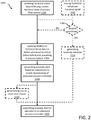
- FIG. 2 is a simplified flowchart of a computer-implemented method 1000 for monitoring the technical status of the industrial process system 300 according to an embodiment.
- functions performed by the computer system 100 are described in the context of the flow chart of FIG. 2 . Therefore, the following description refers to reference numbers of FIG. 1 and FIG. 2 .
- the industrial process system 300 is under control of an advanced process controller APC and has an operation part 330 for processing gas, liquid or solid flow materials.
- the operation 330 includes processing components, such as for example, actuators An, sensors Sn, piping, tanks, etc. as well as the processed materials. Examples of different types of industrial process systems were described earlier.
- the advanced process controller APC is responsive to one or more sensor signals 320. Signals to which the APC is responsive are referred to as the relevant signals herein.
- the APC is very sensitive with regards to the relevant signals and wrong sensor values received from one or more of the sensors Sn can lead to the computation of wrong set points 310 for the low level controllers LLC which control the actuators An.
- Such wrong set points 310 can take the proper operating of the industrial process system at risk because actuators receive inappropriate control instructions via the wrong set points leading to inappropriate behavior or functioning.
- Corrupted signals stand for an abnormal technical status of the respective processing component or flow material.
- a temperature sensor value may be totally wrong (e.g., much higher than the actual temperature) because the sensor is broken or de-calibrated and not because a respective heater is heating too much.
- a flow sensor may provide an actual flow value far below the desired flow value because a pipe or a valve is partially blocked and not because a respective pump is pumping at too low power.
- the computer system 100 can detect such anomalies regarding the technical status of the industrial process system 300.
- an interface module 110 of the computer system 100 receives 1100 technical status data 321 describing the current technical state of the industrial process system 300 with regards to a respective processing component or the processed material.
- the technical status data 321 may correspond to the one or more sensor signals 320 or it may be derived from such signals 320.
- an optional pre-processor module 250 can derive over a time-period features such as, for example, average, max, min, variance, skewness, kurtosis, median, k-peaks, location of maximum, or location of minimum.
- the interface 110 receives from a machine learning module 200 one or more Machine Learning Models MLMn which are trained on historic raw or pre-processed sensor data.
- MLMn Machine Learning Models
- the received technical status data 321 corresponds to the raw sensor data/signals 320
- the received Machine Learning Models are trained on historic raw sensor data.
- the received technical status data 321 corresponds to pre-processed sensor data
- the received Machine Learning Models (MLM) are trained on historic pre-processed data wherein the same features were derived from the original sensor signals for both purposes: the training of the respective MLMn and the anomaly detection.
- An anomaly detection module 120 of the computer system 100 applies 1200 the one or more Machine Learning Models MLMn to the received technical status data 321 to analyze the technical status data for detecting one or more indicators of an abnormal technical status prevailing in the industrial process system 300.
- FIGs. 3A to 3C illustrate details of different embodiments where different numbers of Machine Learning Models are used.
- the anomaly detection module When the application of a particular Machine Learning Model to the received technical status data detects an anomaly indicator the anomaly detection module generates an anomaly alert AA based on this indicator. If multiple Machine Learning Models are applied, each MLM can detect an anomaly indicator.
- the generated anomaly alert AA can include multiple anomaly indicators.
- the anomaly alert AA can be a vector with the various indicators as the vector elements.
- the anomaly detection analysis can be based on different algorithms which are well known in the context of machine learning. Examples for such algorithms include but are not limited to: k-nearest neighbor, local outlier detection, fuzzy logic based outlier detection, multi-variate Gaussian distribution, one-class support vector machine, replicator neural networks, self-organizing maps, deviations from association rules, and deviations from frequent item-sets.
- the anomaly detection 120 then outputs 1400 the anomaly alert AA via the interface 110 to enable deactivating of the advanced process controller APC in case of an anomaly detection for the industrial process system.
- This includes in one embodiment to prompt an operator 10 of the industrial process system with the anomaly alert AA so that the operator takes corrective action 11 in deactivating the APC.
- it includes to send the anomaly alert AA directly to the industrial process system in a machine readable format which can be executed by a computer-implemented control unit of the industrial process system 300 to automatically deactivate the APC in response to the anomaly alert AA.
- the disclosed computer system 100 allows to prevent the APC from computing set-points for LLCs which take the industrial process system operation 330 at risk in response to sensor data 320 of low quality. This is achieved either fully automatically by instructing the industrial process system 300 to deactivate the APC in case of detected anomalies or indirectly by providing the anomaly alert to the operator 10 as a prompt for taking corrective action.
- the computer system 100 may further include a threshold evaluator module 140.
- the threshold evaluator 140 can store 1020 an upper threshold value and a lower threshold value per received technical status data for one or more of the received technical status data.
- the threshold values may be predefined or they may be learned by the respective Machine Learning Models MLMn from the historic sensor data.
- the threshold evaluator 140 can compare 1040 the received technical status data with the threshold values, and generate 1220, irrespective of the evaluation by the anomaly detection module 120, an anomaly indicator for a particular received technical status data if the technical status data falls outside the interval defined by the respective upper and lower thresholds.
- the threshold evaluator 140 provides the generated anomaly indicator to the anomaly detection module 120 where it is merged into the AA vector.
- the threshold evaluator can provide the generated anomaly indicator directly to the interface 110 from where it can be provided as anomaly alert AA to the operator 10 or to the industrial process system 300.
- the threshold evaluator 140 provides a shortcut to generate an anomaly indicator for a corresponding sensor signal by bypassing the anomaly detection function in cases where the anomaly is so large that the technical status data exceed predefined threshold values. As a consequence, in such situations the anomaly alert generation can be speeded up by avoiding the more time consuming computations on the basis of the corresponding Machine Learning Model(s). Further, the threshold evaluator automatically provides the root cause for the anomaly, namely the sensor signal causing the generation of the respective anomaly indicator. Root cause as used herein means the result of a drill down analysis to discover which is the processing component that is causing the detected anomaly.
- Root cause analysis is also advantageous in embodiments where no threshold indicator is used or where the threshold indicator does not identify an anomaly based on the threshold values.
- the operator can initiate the deactivation of the APC and take corrective action also with regards to the processing components which caused the detected anomaly.
- the computer system 100 may further include a post-processor module 130 to determine 1320 one or more root causes amongst the received technical status data 321.
- the determined one or more root causes indicate the origin for the anomaly alert in the industrial process system allowing to take corrective action.
- Such root causes may be determined by different methods.
- a density based screening method may be used where technical status data samples showing anomalies are compared with samples showing no anomalies to identify the most deviating dimensions as root cause signals.
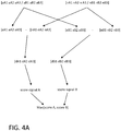
- a detailed example is described in the context of FIG. 4A .
- a scoring anomaly detection may be applied to groups of signals and/or single signals to generate a list of most likely root cause signals. Detailed examples are described in the context of FIGs. 4B, 4C . The group or single signals with highest anomaly scores are the most likely root cause signals.
- FIGs. 3A, 3B, 3C illustrate examples of anomaly alert generation with different levels of granularity regarding root cause identification.
- the anomaly detection can be applied to either the raw sensor data/signals 320 or to pre-processed technical status data 321 derived from such raw sensor data.
- the used Machine Learning Models are trained on historic raw sensor data or historic pre-processed data, respectively.
- a single Machine Learning Model MLMt is applied to technical status data associated with nine sensor signals S1 to S9 of the industrial process system.
- a single anomaly alert AAt is generated in case the application of MLMt to the technical status data leads to the detection of a corresponding anomaly indicator.
- MLMt knows about the dependencies and correlations of all involved sensor signals S1 to S9 which are learned during the training phase of MLMt. Therefore, the anomaly detection sensitivity is highest with regards to recognize an abnormal system behavior of the industrial process system operation because all signal dependencies are implicitly taken into account when applying MLMt to the sensor signals. This high anomaly detection sensitivity comes as a trade off with regards to the root cause identification granularity for the detected anomaly. From the detected anomaly the anomaly detection can only derive that the anomaly is caused by any one or any combination of S1 to S9 (i.e., the industrial process system in its entirety).
- FIG. 3B illustrates an embodiment where multiple Machine Learning Models MLM1 to MLM3 are used.
- the received, technical status data is assigned to a plurality of signal groups SG1 to SG3 where each signal group is processed by a respective Machine Learning Model.
- S1 to S4 are assigned to SG1, S5 to S7 are assigned to SG2, and S8, S9 are assigned to SG3.
- MLM1 is applied to the technical status data of SG1 and can detect an anomaly indicator AA1 for anomalies detected in relation to the corresponding signals S1 to S4.
- MLM2 is applied to the technical status data of SG2 and can detect an anomaly indicator AA2 for anomalies detected in relation to the corresponding signals S5 to S7.
- MLM3 is applied to the technical status data of SG3 and can detect an anomaly indicator AA3 for anomalies detected in relation to the corresponding signals S8 and S9. Based on the anomaly indicators AA1 to AA3 the anomaly alert AAv is generated as a vector with each vector element AA1 to AA3 representing a group anomaly indicator for the respective signal group. Each vector element is determined by applying the respective group specific Machine Learning Model MLM1 to MLM3 to the technical status data assigned to the respective signal group. In this embodiment, root cause analysis is facilitated for the operator because each vector element of the anomaly alert vector AAv relates to a sub-set of the relevant signals.
- the operator immediately knows that the origin of the anomaly is associated with any one or a combination of the signals associated with the technical status data assigned to the corresponding group. That is, the granularity of root cause identification is improved.
- the sensitivity of the anomaly detection by the group specific Machine Learning Models is typically lower than the sensitivity of the single MLMt in FIG. 3A .
- signal groups may be defined by any one or more of the following grouping criteria: grouping based on physical location of the respective signals within the industrial process system, grouping of correlated signals identified by correlation analysis, and grouping of signals with dependencies as a result of domain knowledge.
- Grouping based on physical location includes grouping of sensor signals which are in a defined physical neighborhood inside the industrial process system. Typically, such sensors will show some dependencies and/or correlations (e.g., a temperature sensor being in proximity to a heater, a flow meter being in proximity to a pump or tank, etc.) so that such a grouping can provide acceptable results regarding anomaly detection. Further, this grouping criterion provides immediate feedback to the operator about the potential physical location of the origin of the anomaly.
- Grouping of correlated signals identified by correlation analysis ensures good anomaly detection results.
- the granularity with regards to root cause identification depends on the size of the signal groups. Typically, the more correlated signals are included in a group the better is the anomaly detection result but the lower is the root cause detection granularity.
- Grouping of signals with dependencies as a result of domain knowledge typically is based on the knowledge of dependencies which exist in the processes performed by the industrial process system. Therefore, this embodiment typically leads to good anomaly detection results because of the known dependencies of the grouped signals and at the same time allows process related granularity of root cause identification. In other words, if one of the group specific Machine Learning Models results in an anomaly indicator the operator immediately knows which process in the industrial process system caused the anomaly.
- FIG. 3C illustrates an embodiment where for each sensor signal S1 to S9 an associated Machine Learning Model MLMa to MLMi is provided. That is, each technical status data associated with a corresponding sensor signal is analyzed with regards to abnormal behavior in view of the patterns for the signal learned from the historic data behavior.
- the highest granularity with regards to root cause identification is achieved as for each signal a corresponding anomaly indicator AAa to AAi is computed as a vector element of the anomaly alert vector AAv1. If such an element shows an anomaly for the respective signal, the operator can retrieve the exact origin of the anomaly from the anomaly alert vector because there is a 1:1 correspondence between the respective signal and the corresponding anomaly indicator.
- the sensitivity of the anomaly detection is limited to abnormal behavior of a single signal. Dependencies between signals cannot be handled.
- FIGs. 4A to 4C illustrate different embodiments of the post-processor function.
- FIG. 4A shows an embodiment for determining one or more root causes amongst the received technical status data using density based screening. Thereby, technical status data samples showing anomalies are compared with samples showing no anomalies to identify the most deviating dimensions as root cause signals.
- two signals A, B are sampled over multiple time intervals. For example, a signal value for each of the signals may be sampled every hour. In the example, for both signals the last three samples are analyzed.
- the last three samples are aA1, aA2 and aA3 showing a potential anomaly.
- the last three samples are aB1, aB2 and aB3 showing a potential anomaly.
- the post-processor knows corresponding normal series of samples for signals A and B: nA1, nA2, n A3 and nB1, nB2, nB3.
- the normal samples may correspond to historic data reflecting normal operation of the industrial process system in the past or they may be computed based on a model of the industrial process system which allows to simulate normal operation of the industrial process system. Such normal samples serve as reference samples for the comparison of potentially abnormal samples.
- a deviation score (score signal A, score signal B) is computed.
- the maximum score Max(score A, score B) is likely the origin for the detected anomaly.
- This density based screening approach can be used to post-process individual signals once the anomaly detection generates an anomaly alert.
- the alert may be generated with the highest sensitivity level (a single Machine Learning Model applied to all technical status data).
- the post-processor can then provide a more detailed root cause identification at the signal level by comparing the sampled technical status data which caused the anomaly alert with corresponding normal technical status data wherein comparing includes the application of a distance measure.
- weighted sum or some other distance measure may be used to compute the distance between the normal and abnormal data points. If particular features are derived from two or more signals (e.g., via their cross-correlation, lag, etc.) the features averages can appear in the samples or be otherwise considered in the calculation of the accumulated deviation of the corresponding signals, optionally with a weight reflecting the importance of the signal for the feature.
- FIG. 4B illustrates root cause identification by using anomaly scoring at signal group level.
- an anomaly alert vector AAv was already generated as described in FIG. 3B .
- the post-processor now performs a scoring function on the vector elements (group anomaly indicators).
- a scoring function can be, for example, to determine the maximum value of the vector elements Max(AA1, AA2, AA3) or to sort the vector elements Sorte List (AA1, AA2, AA3) to provide to the operator a prioritized list of with regards to the signal groups which most likely caused the anomaly.
- FIG. 4C illustrates that the same anomaly scoring can be applied to the embodiment where anomaly detection is performed at the single signal level as disclosed in FIG. 3C .
- the length of the anomaly alert vector AAv1 corresponds to the number of signals because for each signal a corresponding Machine Learning Model MLMa to MLMi was used to compute a respective anomaly indicator. That is, the scoring function is applied to AAv1 which provides an improved granularity to the operator for fast identification of the root cause.
- FIG. 5 is a diagram that shows an example of a generic computer device 900 and a generic mobile computer device 950, which may be used with the techniques described here.
- Computing device 900 is intended to represent various forms of digital computers, such as laptops, desktops, workstations, personal digital assistants, servers, blade servers, mainframes, and other appropriate computers.
- Generic computer device may 900 correspond to a computer system 100 as illustrated in FIG. 1 .
- Computing device 950 is intended to represent various forms of mobile devices, such as personal digital assistants, cellular telephones, smart phones, and other similar computing devices.
- computing device 950 may be used by an operator for communication with the computer system 100.
- the components shown here, their connections and relationships, and their functions, are meant to be exemplary only, and are not meant to limit implementations of the inventions described and/or claimed in this document.
- Computing device 900 includes a processor 902, memory 904, a storage device 906, a high-speed interface 908 connecting to memory 904 and high-speed expansion ports 910, and a low speed interface 912 connecting to low speed bus 914 and storage device 906.
- Each of the components 902, 904, 906, 908, 910, and 912 are interconnected using various busses, and may be mounted on a common motherboard or in other manners as appropriate.
- the processor 902 can process instructions for execution within the computing device 900, including instructions stored in the memory 904 or on the storage device 906 to display graphical information for a GUI on an external input/output device, such as display 916 coupled to high speed interface 908.
- multiple processing units and/or multiple buses may be used, as appropriate, along with multiple memories and types of memory.
- multiple computing devices 900 may be connected, with each device providing portions of the necessary operations (e.g., as a server bank, a group of blade servers, or a processing device).
- the memory 904 stores information within the computing device 900.
- the memory 904 is a volatile memory unit or units.
- the memory 904 is a non-volatile memory unit or units.
- the memory 904 may also be another form of computer-readable medium, such as a magnetic or optical disk.
- the storage device 906 is capable of providing mass storage for the computing device 900.
- the storage device 906 may be or contain a computer-readable medium, such as a floppy disk device, a hard disk device, an optical disk device, or a tape device, a flash memory or other similar solid state memory device, or an array of devices, including devices in a storage area network or other configurations.
- a computer program product can be tangibly embodied in an information carrier.
- the computer program product may also contain instructions that, when executed, perform one or more methods, such as those described above.
- the information carrier is a computer- or machine-readable medium, such as the memory 904, the storage device 906, or memory on processor 902.
- the high speed controller 908 manages bandwidth-intensive operations for the computing device 900, while the low speed controller 912 manages lower bandwidth-intensive operations.
- the high-speed controller 908 is coupled to memory 904, display 916 (e.g., through a graphics processor or accelerator), and to high-speed expansion ports 910, which may accept various expansion cards (not shown).
- low-speed controller 912 is coupled to storage device 906 and low-speed expansion port 914.
- the low-speed expansion port which may include various communication ports (e.g., USB, Bluetooth, Ethernet, wireless Ethernet) may be coupled to one or more input/output devices, such as a keyboard, a pointing device, a scanner, or a networking device such as a switch or router, e.g., through a network adapter.
- input/output devices such as a keyboard, a pointing device, a scanner, or a networking device such as a switch or router, e.g., through a network adapter.
- the computing device 900 may be implemented in a number of different forms, as shown in the figure. For example, it may be implemented as a standard server 920, or multiple times in a group of such servers. It may also be implemented as part of a rack server system 924. In addition, it may be implemented in a personal computer such as a laptop computer 922. Alternatively, components from computing device 900 may be combined with other components in a mobile device (not shown), such as device 950. Each of such devices may contain one or more of computing device 900, 950, and an entire system may be made up of multiple computing devices 900, 950 communicating with each other.
- Computing device 950 includes a processor 952, memory 964, an input/output device such as a display 954, a communication interface 966, and a transceiver 968, among other components.
- the device 950 may also be provided with a storage device, such as a microdrive or other device, to provide additional storage.
- a storage device such as a microdrive or other device, to provide additional storage.
- Each of the components 950, 952, 964, 954, 966, and 968 are interconnected using various buses, and several of the components may be mounted on a common motherboard or in other manners as appropriate.
- the processor 952 can execute instructions within the computing device 950, including instructions stored in the memory 964.
- the processor may be implemented as a chipset of chips that include separate and multiple analog and digital processing units.
- the processor may provide, for example, for coordination of the other components of the device 950, such as control of user interfaces, applications run by device 950, and wireless communication by device 950.
- Processor 952 may communicate with a user through control interface 958 and display interface 956 coupled to a display 954.
- the display 954 may be, for example, a TFT LCD (Thin-Film-Transistor Liquid Crystal Display) or an OLED (Organic Light Emitting Diode) display, or other appropriate display technology.
- the display interface 956 may comprise appropriate circuitry for driving the display 954 to present graphical and other information to a user.
- the control interface 958 may receive commands from a user and convert them for submission to the processor 952.
- an external interface 962 may be provided in communication with processor 952, so as to enable near area communication of device 950 with other devices.
- External interface 962 may provide, for example, for wired communication in some implementations, or for wireless communication in other implementations, and multiple interfaces may also be used.
- the memory 964 stores information within the computing device 950.
- the memory 964 can be implemented as one or more of a computer-readable medium or media, a volatile memory unit or units, or a non-volatile memory unit or units.
- Expansion memory 984 may also be provided and connected to device 950 through expansion interface 982, which may include, for example, a SIMM (Single In Line Memory Module) card interface.
- SIMM Single In Line Memory Module
- expansion memory 984 may provide extra storage space for device 950, or may also store applications or other information for device 950.
- expansion memory 984 may include instructions to carry out or supplement the processes described above, and may include secure information also.
- expansion memory 984 may act as a security module for device 950, and may be programmed with instructions that permit secure use of device 950.
- secure applications may be provided via the SIMM cards, along with additional information, such as placing the identifying information on the SIMM card in a non-hackable manner.
- the memory may include, for example, flash memory and/or NVRAM memory, as discussed below.
- a computer program product is tangibly embodied in an information carrier.
- the computer program product contains instructions that, when executed, perform one or more methods, such as those described above.
- the information carrier is a computer- or machine-readable medium, such as the memory 964, expansion memory 984, or memory on processor 952, that may be received, for example, over transceiver 968 or external interface 962.
- Device 950 may communicate wirelessly through communication interface 966, which may include digital signal processing circuitry where necessary. Communication interface 966 may provide for communications under various modes or protocols, such as GSM voice calls, SMS, EMS, or MMS messaging, CDMA, TDMA, PDC, WCDMA, CDMA2000, or GPRS, EDGE, UMTS, LTE, among others. Such communication may occur, for example, through radio-frequency transceiver 968. In addition, short-range communication may occur, such as using a Bluetooth, WiFi, or other such transceiver (not shown). In addition, GPS (Global Positioning System) receiver module 980 may provide additional navigation- and location-related wireless data to device 950, which may be used as appropriate by applications running on device 950.
- GPS Global Positioning System
- Device 950 may also communicate audibly using audio codec 960, which may receive spoken information from a user and convert it to usable digital information. Audio codec 960 may likewise generate audible sound for a user, such as through a speaker, e.g., in a handset of device 950. Such sound may include sound from voice telephone calls, may include recorded sound (e.g., voice messages, music files, etc.) and may also include sound generated by applications operating on device 950.
- Audio codec 960 may receive spoken information from a user and convert it to usable digital information. Audio codec 960 may likewise generate audible sound for a user, such as through a speaker, e.g., in a handset of device 950. Such sound may include sound from voice telephone calls, may include recorded sound (e.g., voice messages, music files, etc.) and may also include sound generated by applications operating on device 950.
- the computing device 950 may be implemented in a number of different forms, as shown in the figure. For example, it may be implemented as a cellular telephone 980. It may also be implemented as part of a smart phone 982, personal digital assistant, or other similar mobile device.
- implementations of the systems and techniques described here can be realized in digital electronic circuitry, integrated circuitry, specially designed ASICs (application specific integrated circuits), computer hardware, firmware, software, and/or combinations thereof.
- ASICs application specific integrated circuits
- These various implementations can include implementation in one or more computer programs that are executable and/or interpretable on a programmable system including at least one programmable processor, which may be special or general purpose, coupled to receive data and instructions from, and to transmit data and instructions to, a storage system, at least one input device, and at least one output device.
- the systems and techniques described here can be implemented on a computer having a display device (e.g., a CRT (cathode ray tube) or LCD (liquid crystal display) monitor) for displaying information to the user and a keyboard and a pointing device (e.g., a mouse or a trackball) by which the user can provide input to the computer.
- a display device e.g., a CRT (cathode ray tube) or LCD (liquid crystal display) monitor
- a keyboard and a pointing device e.g., a mouse or a trackball
- Other kinds of devices can be used to provide for interaction with a user as well; for example, feedback provided to the user can be any form of sensory feedback (e.g., visual feedback, auditory feedback, or tactile feedback); and input from the user can be received in any form, including acoustic, speech, or tactile input.
- the systems and techniques described here can be implemented in a computing device that includes a backend component (e.g., as a data server), or that includes a middleware component (e.g., an application server), or that includes a front end component (e.g., a client computer having a graphical user interface or a Web browser through which a user can interact with an implementation of the systems and techniques described here), or any combination of such backend, middleware, or frontend components.
- the components of the system can be interconnected by any form or medium of digital data communication (e.g., a communication network). Examples of communication networks include a local area network ("LAN”), a wireless local area network (“WLAN”), a wide area network (“WAN”), and the Internet.
- LAN local area network
- WLAN wireless local area network
- WAN wide area network
- the Internet the global information network
- the computing device can include clients and servers.
- a client and server are generally remote from each other and typically interact through a communication network.
- the relationship of client and server arises by virtue of computer programs running on the respective computers and having a client-server relationship to each other.
Landscapes
- Engineering & Computer Science (AREA)
- Physics & Mathematics (AREA)
- Automation & Control Theory (AREA)
- General Physics & Mathematics (AREA)
- Evolutionary Computation (AREA)
- Artificial Intelligence (AREA)
- Life Sciences & Earth Sciences (AREA)
- Bioinformatics & Cheminformatics (AREA)
- Bioinformatics & Computational Biology (AREA)
- Evolutionary Biology (AREA)
- Medical Informatics (AREA)
- Software Systems (AREA)
- Health & Medical Sciences (AREA)
- Computer Vision & Pattern Recognition (AREA)
- Mathematical Physics (AREA)
- Testing And Monitoring For Control Systems (AREA)
Priority Applications (4)
| Application Number | Priority Date | Filing Date | Title |
|---|---|---|---|
| EP17162852.2A EP3379357B1 (fr) | 2017-03-24 | 2017-03-24 | Système informatique et procédé de surveillance de l'état de systèmes de processus industriel |
| CN201880020738.0A CN110431503B (zh) | 2017-03-24 | 2018-03-14 | 用于监测工业过程系统的技术状态的计算机系统和方法 |
| PCT/EP2018/056445 WO2018172166A1 (fr) | 2017-03-24 | 2018-03-14 | Système informatique et procédé de surveillance de l'état technique de systèmes de processus industriels |
| US16/576,832 US10969774B2 (en) | 2017-03-24 | 2019-09-20 | Computer system and method for monitoring the technical state of industrial process systems |
Applications Claiming Priority (1)
| Application Number | Priority Date | Filing Date | Title |
|---|---|---|---|
| EP17162852.2A EP3379357B1 (fr) | 2017-03-24 | 2017-03-24 | Système informatique et procédé de surveillance de l'état de systèmes de processus industriel |
Publications (2)
| Publication Number | Publication Date |
|---|---|
| EP3379357A1 true EP3379357A1 (fr) | 2018-09-26 |
| EP3379357B1 EP3379357B1 (fr) | 2019-07-10 |
Family
ID=58640662
Family Applications (1)
| Application Number | Title | Priority Date | Filing Date |
|---|---|---|---|
| EP17162852.2A Active EP3379357B1 (fr) | 2017-03-24 | 2017-03-24 | Système informatique et procédé de surveillance de l'état de systèmes de processus industriel |
Country Status (4)
| Country | Link |
|---|---|
| US (1) | US10969774B2 (fr) |
| EP (1) | EP3379357B1 (fr) |
| CN (1) | CN110431503B (fr) |
| WO (1) | WO2018172166A1 (fr) |
Cited By (11)
| Publication number | Priority date | Publication date | Assignee | Title |
|---|---|---|---|---|
| EP3657283A1 (fr) * | 2018-11-21 | 2020-05-27 | Siemens Aktiengesellschaft | Procédé de détermination d'un ensemble de données fusionnées |
| FR3089024A1 (fr) | 2018-11-26 | 2020-05-29 | Braincube | Appareil numérique de régulation d’un processus industriel |
| WO2020109945A1 (fr) | 2018-11-26 | 2020-06-04 | Braincube | Procede de regulation d'un processus industriel |
| WO2020128342A1 (fr) * | 2018-12-20 | 2020-06-25 | Alizent International | Procédé et système de détection de déviation de fonctionnement d'un équipement industriel |
| WO2020173581A1 (fr) * | 2019-02-27 | 2020-09-03 | Siemens Aktiengesellschaft | Système, dispositif et procédé de surveillance d'état d'une installation technique |
| FR3094504A1 (fr) | 2019-03-29 | 2020-10-02 | Braincube | Appareil numérique de régulation d’un processus industriel avec contexte |
| EP3764184A4 (fr) * | 2019-03-26 | 2021-04-21 | Toshiba Mitsubishi-Electric Industrial Systems Corporation | Dispositif d'aide à la détermination d'anomalies |
| EP3916504A1 (fr) * | 2020-05-28 | 2021-12-01 | Thilo Heffner | Prévention des pertes numériques 4.0 |
| WO2022003011A1 (fr) * | 2020-06-30 | 2022-01-06 | Siemens Aktiengesellschaft | Procédé et système de transmission d'une alerte portant sur des scores d'anomalies attribués à des données d'entrée |
| WO2022115729A1 (fr) * | 2020-11-30 | 2022-06-02 | Kcf Technologies, Inc. | Optimisation de détection d'anomalie |
| WO2022194385A1 (fr) * | 2021-03-19 | 2022-09-22 | Huawei Technologies Co., Ltd. | Procédé et appareil d'analyse multidimensionnelle de causes profondes |
Families Citing this family (18)
| Publication number | Priority date | Publication date | Assignee | Title |
|---|---|---|---|---|
| US11307117B2 (en) * | 2017-09-04 | 2022-04-19 | Amper Technologies, Inc. | System and method for interpretation and analysis of manufacturing activity |
| US20200081422A1 (en) * | 2018-09-12 | 2020-03-12 | Samsung Electronics Co., Ltd. | Methods and systems for predicting health of products in a manufacturing process |
| JP2022531714A (ja) | 2019-05-09 | 2022-07-08 | デュール システムズ アーゲー | 分析方法及びそのための装置 |
| CN113795800A (zh) * | 2019-05-09 | 2021-12-14 | 杜尔系统股份公司 | 用于对工件进行检验的方法、检验设备和处理设备 |
| JP7458097B2 (ja) * | 2020-02-28 | 2024-03-29 | ナノトロニクス イメージング インコーポレイテッド | 工場制御システムをインテリジェントにエミュレートし、応答データをシミュレートするための方法、システム及び装置 |
| CN111325472A (zh) * | 2020-02-28 | 2020-06-23 | 北京思特奇信息技术股份有限公司 | 一种异常数据检测方法和系统 |
| DE102020109858A1 (de) * | 2020-04-08 | 2021-10-14 | Balluff Gmbh | Verfahren zum Betreiben eines Systems |
| TWI723861B (zh) * | 2020-04-30 | 2021-04-01 | 致伸科技股份有限公司 | 外掛式生產輔助管控系統 |
| CN111654695A (zh) * | 2020-07-30 | 2020-09-11 | 重庆盛泰光电有限公司 | 摄像头模组检测数据管理系统 |
| CN112114571B (zh) * | 2020-09-24 | 2021-11-30 | 中冶赛迪重庆信息技术有限公司 | 一种工业数据处理方法、系统及设备 |
| KR102420994B1 (ko) * | 2020-10-14 | 2022-07-18 | 한국전자통신연구원 | 딥러닝을 이용한 제어 시스템의 이상 탐지 장치 및 방법 |
| CN113210939B (zh) * | 2021-05-08 | 2023-03-14 | 武汉钢铁有限公司 | 一种焊接系统控制方法及装置 |
| WO2023043425A1 (fr) * | 2021-09-14 | 2023-03-23 | Hewlett-Packard Development Company, L.P. | Déterminations d'écart de composants |
| CN113960965B (zh) * | 2021-09-26 | 2024-04-23 | 北京百度网讯科技有限公司 | 数据处理方法、装置、电子设备和可读存储介质 |
| EP4184267A1 (fr) | 2021-11-22 | 2023-05-24 | Abb Schweiz Ag | Procédé permettant de déterminer l'état d'un processus industriel |
| US20230186121A1 (en) * | 2021-12-10 | 2023-06-15 | International Business Machines Corporation | Computer optimization of task performance through dynamic sensing |
| CN114235108B (zh) * | 2021-12-24 | 2023-08-15 | 华中科技大学无锡研究院 | 基于数据分析燃气流量计异常状态检测方法和装置 |
| CN117671396B (zh) * | 2024-02-02 | 2024-04-26 | 新疆盛诚工程建设有限责任公司 | 施工进度的智能监控预警系统及方法 |
Citations (3)
| Publication number | Priority date | Publication date | Assignee | Title |
|---|---|---|---|---|
| WO2011034805A1 (fr) * | 2009-09-17 | 2011-03-24 | Siemens Aktiengesellschaft | Apprentissage des défaillances supervisé utilisant des échantillons générés par règle pour la surveillance de l'état des machines |
| US20120150335A1 (en) * | 2010-12-08 | 2012-06-14 | L'air Liquide Societe Anonyme Pour L'etude Et L'exploitation Des Procedes Georges Claude | Performance Monitoring Of Advanced Process Control Systems |
| US20160320768A1 (en) * | 2015-05-01 | 2016-11-03 | Aspen Technology, Inc. | Computer System And Method For Causality Analysis Using Hybrid First-Principles And Inferential Model |
Family Cites Families (8)
| Publication number | Priority date | Publication date | Assignee | Title |
|---|---|---|---|---|
| US8266095B2 (en) * | 2006-06-19 | 2012-09-11 | Hitachi Kokusai Electric, Inc. | Substrate processing system and operation inspecting method |
| CN102265227B (zh) * | 2008-10-20 | 2013-09-04 | 西门子公司 | 用于在机器状况监视中创建状态估计模型的方法和设备 |
| WO2011046869A2 (fr) * | 2009-10-12 | 2011-04-21 | Abbott Patrick D | Système de surveillance d'équipements ciblés et procédé d'optimisation de la fiabilité des équipements |
| US9355007B1 (en) * | 2013-07-15 | 2016-05-31 | Amazon Technologies, Inc. | Identifying abnormal hosts using cluster processing |
| US20160330225A1 (en) * | 2014-01-13 | 2016-11-10 | Brightsource Industries (Israel) Ltd. | Systems, Methods, and Devices for Detecting Anomalies in an Industrial Control System |
| US10699211B2 (en) * | 2016-02-29 | 2020-06-30 | Oracle International Corporation | Supervised method for classifying seasonal patterns |
| CN106483942B (zh) * | 2016-09-20 | 2019-06-04 | 孙敬玺 | 一种半导体制造设备和工艺的智能控制系统及方法 |
| US11062230B2 (en) * | 2017-02-28 | 2021-07-13 | International Business Machines Corporation | Detecting data anomalies |
-
2017
- 2017-03-24 EP EP17162852.2A patent/EP3379357B1/fr active Active
-
2018
- 2018-03-14 WO PCT/EP2018/056445 patent/WO2018172166A1/fr active Application Filing
- 2018-03-14 CN CN201880020738.0A patent/CN110431503B/zh active Active
-
2019
- 2019-09-20 US US16/576,832 patent/US10969774B2/en active Active
Patent Citations (3)
| Publication number | Priority date | Publication date | Assignee | Title |
|---|---|---|---|---|
| WO2011034805A1 (fr) * | 2009-09-17 | 2011-03-24 | Siemens Aktiengesellschaft | Apprentissage des défaillances supervisé utilisant des échantillons générés par règle pour la surveillance de l'état des machines |
| US20120150335A1 (en) * | 2010-12-08 | 2012-06-14 | L'air Liquide Societe Anonyme Pour L'etude Et L'exploitation Des Procedes Georges Claude | Performance Monitoring Of Advanced Process Control Systems |
| US20160320768A1 (en) * | 2015-05-01 | 2016-11-03 | Aspen Technology, Inc. | Computer System And Method For Causality Analysis Using Hybrid First-Principles And Inferential Model |
Cited By (14)
| Publication number | Priority date | Publication date | Assignee | Title |
|---|---|---|---|---|
| EP3657283A1 (fr) * | 2018-11-21 | 2020-05-27 | Siemens Aktiengesellschaft | Procédé de détermination d'un ensemble de données fusionnées |
| FR3089024A1 (fr) | 2018-11-26 | 2020-05-29 | Braincube | Appareil numérique de régulation d’un processus industriel |
| WO2020109945A1 (fr) | 2018-11-26 | 2020-06-04 | Braincube | Procede de regulation d'un processus industriel |
| WO2020128342A1 (fr) * | 2018-12-20 | 2020-06-25 | Alizent International | Procédé et système de détection de déviation de fonctionnement d'un équipement industriel |
| FR3090914A1 (fr) * | 2018-12-20 | 2020-06-26 | Alizent International | Procédé et système de détection de déviation de fonctionnement d’un équipement industriel |
| WO2020173581A1 (fr) * | 2019-02-27 | 2020-09-03 | Siemens Aktiengesellschaft | Système, dispositif et procédé de surveillance d'état d'une installation technique |
| US11392114B2 (en) | 2019-03-26 | 2022-07-19 | Toshiba Mitsubishi-Electric Industrial Systems Corporation | Abnormality determination support apparatus |
| EP3764184A4 (fr) * | 2019-03-26 | 2021-04-21 | Toshiba Mitsubishi-Electric Industrial Systems Corporation | Dispositif d'aide à la détermination d'anomalies |
| FR3094504A1 (fr) | 2019-03-29 | 2020-10-02 | Braincube | Appareil numérique de régulation d’un processus industriel avec contexte |
| EP3916504A1 (fr) * | 2020-05-28 | 2021-12-01 | Thilo Heffner | Prévention des pertes numériques 4.0 |
| WO2022003011A1 (fr) * | 2020-06-30 | 2022-01-06 | Siemens Aktiengesellschaft | Procédé et système de transmission d'une alerte portant sur des scores d'anomalies attribués à des données d'entrée |
| WO2022115729A1 (fr) * | 2020-11-30 | 2022-06-02 | Kcf Technologies, Inc. | Optimisation de détection d'anomalie |
| US11499892B2 (en) | 2020-11-30 | 2022-11-15 | Kcf Technologies, Inc. | Optimization for anomaly detection |
| WO2022194385A1 (fr) * | 2021-03-19 | 2022-09-22 | Huawei Technologies Co., Ltd. | Procédé et appareil d'analyse multidimensionnelle de causes profondes |
Also Published As
| Publication number | Publication date |
|---|---|
| US20200012270A1 (en) | 2020-01-09 |
| CN110431503A (zh) | 2019-11-08 |
| EP3379357B1 (fr) | 2019-07-10 |
| WO2018172166A1 (fr) | 2018-09-27 |
| US10969774B2 (en) | 2021-04-06 |
| CN110431503B (zh) | 2021-02-09 |
Similar Documents
| Publication | Publication Date | Title |
|---|---|---|
| EP3379357B1 (fr) | Système informatique et procédé de surveillance de l'état de systèmes de processus industriel | |
| US11521105B2 (en) | Machine learning device and machine learning method for learning fault prediction of main shaft or motor which drives main shaft, and fault prediction device and fault prediction system including machine learning device | |
| US10592821B2 (en) | Self-learning fault detection for HVAC systems | |
| ES2871348T3 (es) | Sistema y procedimiento para detectar y medir anomalías en la señalización procedente de componentes utilizados en procesos industriales | |
| CN111385140B (zh) | 生成监控网络物理系统的数据以早期确定异常的系统和方法 | |
| US20140351642A1 (en) | System and methods for automated plant asset failure detection | |
| EP2904299B1 (fr) | Procedes et appareils de calibration de dispositif de traitement | |
| US20200150601A1 (en) | Solution for controlling a target system | |
| EP3859455B1 (fr) | Appareil d'apprentissage, procédé d'apprentissage, programme d'apprentissage, appareil de détermination, procédé de détermination, programme de détermination et support lisible par ordinateur | |
| US10437265B2 (en) | Performance monitoring of pump-valve system | |
| WO2020242553A1 (fr) | Prédiction de panne utilisant une identification de capteur basée sur un gradient | |
| US20090259331A1 (en) | Automated system for checking proposed human adjustments to operational or planning parameters at a plant | |
| EP3904987B1 (fr) | Appareil de prise en charge de commande, procédé de prise en charge de commande, programme de prise en charge de commande, support lisible sur un ordinateur sur lequel est enregistré un programme de prise en charge de commande et système de commande | |
| US11645794B2 (en) | Monitoring apparatus, monitoring method, and computer-readable medium having recorded thereon monitoring program | |
| CN111555899B (zh) | 告警规则配置方法、设备状态监测方法、装置和存储介质 | |
| EP4206963A1 (fr) | Système et procédé de diagnostic et de surveillance d'anomalies d'un système cyberphysique | |
| JP2016532221A (ja) | モデル適合のための装置および方法 | |
| US20220188570A1 (en) | Learning apparatus, learning method, computer program and recording medium | |
| US20230004153A1 (en) | Diagnosing device, diagnosing method, and program | |
| US20220253461A1 (en) | Time-series data processing method | |
| US20200112577A1 (en) | Graph-based sensor ranking | |
| US20210400069A1 (en) | Information processing apparatus | |
| JP2015232914A (ja) | 異常診断装置、異常診断方法及び異常診断プログラム | |
| TWI812329B (zh) | 用於判定網路攻擊及產生警告之製造系統及電腦實施方法 | |
| US11885720B2 (en) | Time series data processing method |
Legal Events
| Date | Code | Title | Description |
|---|---|---|---|
| PUAI | Public reference made under article 153(3) epc to a published international application that has entered the european phase |
Free format text: ORIGINAL CODE: 0009012 |
|
| STAA | Information on the status of an ep patent application or granted ep patent |
Free format text: STATUS: THE APPLICATION HAS BEEN PUBLISHED |
|
| AK | Designated contracting states |
Kind code of ref document: A1 Designated state(s): AL AT BE BG CH CY CZ DE DK EE ES FI FR GB GR HR HU IE IS IT LI LT LU LV MC MK MT NL NO PL PT RO RS SE SI SK SM TR |
|
| AX | Request for extension of the european patent |
Extension state: BA ME |
|
| STAA | Information on the status of an ep patent application or granted ep patent |
Free format text: STATUS: REQUEST FOR EXAMINATION WAS MADE |
|
| 17P | Request for examination filed |
Effective date: 20190102 |
|
| RBV | Designated contracting states (corrected) |
Designated state(s): AL AT BE BG CH CY CZ DE DK EE ES FI FR GB GR HR HU IE IS IT LI LT LU LV MC MK MT NL NO PL PT RO RS SE SI SK SM TR |
|
| GRAP | Despatch of communication of intention to grant a patent |
Free format text: ORIGINAL CODE: EPIDOSNIGR1 |
|
| STAA | Information on the status of an ep patent application or granted ep patent |
Free format text: STATUS: GRANT OF PATENT IS INTENDED |
|
| INTG | Intention to grant announced |
Effective date: 20190305 |
|
| GRAS | Grant fee paid |
Free format text: ORIGINAL CODE: EPIDOSNIGR3 |
|
| GRAA | (expected) grant |
Free format text: ORIGINAL CODE: 0009210 |
|
| STAA | Information on the status of an ep patent application or granted ep patent |
Free format text: STATUS: THE PATENT HAS BEEN GRANTED |
|
| AK | Designated contracting states |
Kind code of ref document: B1 Designated state(s): AL AT BE BG CH CY CZ DE DK EE ES FI FR GB GR HR HU IE IS IT LI LT LU LV MC MK MT NL NO PL PT RO RS SE SI SK SM TR |
|
| REG | Reference to a national code |
Ref country code: GB Ref legal event code: FG4D |
|
| REG | Reference to a national code |
Ref country code: CH Ref legal event code: EP Ref country code: AT Ref legal event code: REF Ref document number: 1154234 Country of ref document: AT Kind code of ref document: T Effective date: 20190715 |
|
| REG | Reference to a national code |
Ref country code: DE Ref legal event code: R096 Ref document number: 602017005099 Country of ref document: DE |
|
| REG | Reference to a national code |
Ref country code: IE Ref legal event code: FG4D |
|
| REG | Reference to a national code |
Ref country code: SE Ref legal event code: TRGR |
|
| REG | Reference to a national code |
Ref country code: NL Ref legal event code: MP Effective date: 20190710 |
|
| REG | Reference to a national code |
Ref country code: LT Ref legal event code: MG4D |
|
| REG | Reference to a national code |
Ref country code: NO Ref legal event code: T2 Effective date: 20190710 |
|
| REG | Reference to a national code |
Ref country code: AT Ref legal event code: MK05 Ref document number: 1154234 Country of ref document: AT Kind code of ref document: T Effective date: 20190710 |
|
| PG25 | Lapsed in a contracting state [announced via postgrant information from national office to epo] |
Ref country code: LT Free format text: LAPSE BECAUSE OF FAILURE TO SUBMIT A TRANSLATION OF THE DESCRIPTION OR TO PAY THE FEE WITHIN THE PRESCRIBED TIME-LIMIT Effective date: 20190710 Ref country code: PT Free format text: LAPSE BECAUSE OF FAILURE TO SUBMIT A TRANSLATION OF THE DESCRIPTION OR TO PAY THE FEE WITHIN THE PRESCRIBED TIME-LIMIT Effective date: 20191111 Ref country code: HR Free format text: LAPSE BECAUSE OF FAILURE TO SUBMIT A TRANSLATION OF THE DESCRIPTION OR TO PAY THE FEE WITHIN THE PRESCRIBED TIME-LIMIT Effective date: 20190710 Ref country code: NL Free format text: LAPSE BECAUSE OF FAILURE TO SUBMIT A TRANSLATION OF THE DESCRIPTION OR TO PAY THE FEE WITHIN THE PRESCRIBED TIME-LIMIT Effective date: 20190710 Ref country code: BG Free format text: LAPSE BECAUSE OF FAILURE TO SUBMIT A TRANSLATION OF THE DESCRIPTION OR TO PAY THE FEE WITHIN THE PRESCRIBED TIME-LIMIT Effective date: 20191010 Ref country code: AT Free format text: LAPSE BECAUSE OF FAILURE TO SUBMIT A TRANSLATION OF THE DESCRIPTION OR TO PAY THE FEE WITHIN THE PRESCRIBED TIME-LIMIT Effective date: 20190710 |
|
| PG25 | Lapsed in a contracting state [announced via postgrant information from national office to epo] |
Ref country code: ES Free format text: LAPSE BECAUSE OF FAILURE TO SUBMIT A TRANSLATION OF THE DESCRIPTION OR TO PAY THE FEE WITHIN THE PRESCRIBED TIME-LIMIT Effective date: 20190710 Ref country code: IS Free format text: LAPSE BECAUSE OF FAILURE TO SUBMIT A TRANSLATION OF THE DESCRIPTION OR TO PAY THE FEE WITHIN THE PRESCRIBED TIME-LIMIT Effective date: 20191110 Ref country code: GR Free format text: LAPSE BECAUSE OF FAILURE TO SUBMIT A TRANSLATION OF THE DESCRIPTION OR TO PAY THE FEE WITHIN THE PRESCRIBED TIME-LIMIT Effective date: 20191011 Ref country code: RS Free format text: LAPSE BECAUSE OF FAILURE TO SUBMIT A TRANSLATION OF THE DESCRIPTION OR TO PAY THE FEE WITHIN THE PRESCRIBED TIME-LIMIT Effective date: 20190710 Ref country code: AL Free format text: LAPSE BECAUSE OF FAILURE TO SUBMIT A TRANSLATION OF THE DESCRIPTION OR TO PAY THE FEE WITHIN THE PRESCRIBED TIME-LIMIT Effective date: 20190710 Ref country code: LV Free format text: LAPSE BECAUSE OF FAILURE TO SUBMIT A TRANSLATION OF THE DESCRIPTION OR TO PAY THE FEE WITHIN THE PRESCRIBED TIME-LIMIT Effective date: 20190710 |
|
| PG25 | Lapsed in a contracting state [announced via postgrant information from national office to epo] |
Ref country code: TR Free format text: LAPSE BECAUSE OF FAILURE TO SUBMIT A TRANSLATION OF THE DESCRIPTION OR TO PAY THE FEE WITHIN THE PRESCRIBED TIME-LIMIT Effective date: 20190710 |
|
| PG25 | Lapsed in a contracting state [announced via postgrant information from national office to epo] |
Ref country code: RO Free format text: LAPSE BECAUSE OF FAILURE TO SUBMIT A TRANSLATION OF THE DESCRIPTION OR TO PAY THE FEE WITHIN THE PRESCRIBED TIME-LIMIT Effective date: 20190710 Ref country code: EE Free format text: LAPSE BECAUSE OF FAILURE TO SUBMIT A TRANSLATION OF THE DESCRIPTION OR TO PAY THE FEE WITHIN THE PRESCRIBED TIME-LIMIT Effective date: 20190710 Ref country code: DK Free format text: LAPSE BECAUSE OF FAILURE TO SUBMIT A TRANSLATION OF THE DESCRIPTION OR TO PAY THE FEE WITHIN THE PRESCRIBED TIME-LIMIT Effective date: 20190710 Ref country code: PL Free format text: LAPSE BECAUSE OF FAILURE TO SUBMIT A TRANSLATION OF THE DESCRIPTION OR TO PAY THE FEE WITHIN THE PRESCRIBED TIME-LIMIT Effective date: 20190710 |
|
| PG25 | Lapsed in a contracting state [announced via postgrant information from national office to epo] |
Ref country code: CZ Free format text: LAPSE BECAUSE OF FAILURE TO SUBMIT A TRANSLATION OF THE DESCRIPTION OR TO PAY THE FEE WITHIN THE PRESCRIBED TIME-LIMIT Effective date: 20190710 Ref country code: SK Free format text: LAPSE BECAUSE OF FAILURE TO SUBMIT A TRANSLATION OF THE DESCRIPTION OR TO PAY THE FEE WITHIN THE PRESCRIBED TIME-LIMIT Effective date: 20190710 Ref country code: IS Free format text: LAPSE BECAUSE OF FAILURE TO SUBMIT A TRANSLATION OF THE DESCRIPTION OR TO PAY THE FEE WITHIN THE PRESCRIBED TIME-LIMIT Effective date: 20200224 Ref country code: SM Free format text: LAPSE BECAUSE OF FAILURE TO SUBMIT A TRANSLATION OF THE DESCRIPTION OR TO PAY THE FEE WITHIN THE PRESCRIBED TIME-LIMIT Effective date: 20190710 |
|
| REG | Reference to a national code |
Ref country code: DE Ref legal event code: R097 Ref document number: 602017005099 Country of ref document: DE |
|
| PLBE | No opposition filed within time limit |
Free format text: ORIGINAL CODE: 0009261 |
|
| STAA | Information on the status of an ep patent application or granted ep patent |
Free format text: STATUS: NO OPPOSITION FILED WITHIN TIME LIMIT |
|
| PG2D | Information on lapse in contracting state deleted |
Ref country code: IS |
|
| 26N | No opposition filed |
Effective date: 20200603 |
|
| PG25 | Lapsed in a contracting state [announced via postgrant information from national office to epo] |
Ref country code: SI Free format text: LAPSE BECAUSE OF FAILURE TO SUBMIT A TRANSLATION OF THE DESCRIPTION OR TO PAY THE FEE WITHIN THE PRESCRIBED TIME-LIMIT Effective date: 20190710 |
|
| PG25 | Lapsed in a contracting state [announced via postgrant information from national office to epo] |
Ref country code: MC Free format text: LAPSE BECAUSE OF FAILURE TO SUBMIT A TRANSLATION OF THE DESCRIPTION OR TO PAY THE FEE WITHIN THE PRESCRIBED TIME-LIMIT Effective date: 20190710 |
|
| REG | Reference to a national code |
Ref country code: BE Ref legal event code: MM Effective date: 20200331 |
|
| PG25 | Lapsed in a contracting state [announced via postgrant information from national office to epo] |
Ref country code: LU Free format text: LAPSE BECAUSE OF NON-PAYMENT OF DUE FEES Effective date: 20200324 |
|
| PG25 | Lapsed in a contracting state [announced via postgrant information from national office to epo] |
Ref country code: FR Free format text: LAPSE BECAUSE OF NON-PAYMENT OF DUE FEES Effective date: 20200331 |
|
| PG25 | Lapsed in a contracting state [announced via postgrant information from national office to epo] |
Ref country code: BE Free format text: LAPSE BECAUSE OF NON-PAYMENT OF DUE FEES Effective date: 20200331 |
|
| PG25 | Lapsed in a contracting state [announced via postgrant information from national office to epo] |
Ref country code: MT Free format text: LAPSE BECAUSE OF FAILURE TO SUBMIT A TRANSLATION OF THE DESCRIPTION OR TO PAY THE FEE WITHIN THE PRESCRIBED TIME-LIMIT Effective date: 20190710 Ref country code: CY Free format text: LAPSE BECAUSE OF FAILURE TO SUBMIT A TRANSLATION OF THE DESCRIPTION OR TO PAY THE FEE WITHIN THE PRESCRIBED TIME-LIMIT Effective date: 20190710 |
|
| PG25 | Lapsed in a contracting state [announced via postgrant information from national office to epo] |
Ref country code: MK Free format text: LAPSE BECAUSE OF FAILURE TO SUBMIT A TRANSLATION OF THE DESCRIPTION OR TO PAY THE FEE WITHIN THE PRESCRIBED TIME-LIMIT Effective date: 20190710 |
|
| PGFP | Annual fee paid to national office [announced via postgrant information from national office to epo] |
Ref country code: NO Payment date: 20230324 Year of fee payment: 7 Ref country code: IE Payment date: 20230324 Year of fee payment: 7 Ref country code: FI Payment date: 20230321 Year of fee payment: 7 |
|
| PGFP | Annual fee paid to national office [announced via postgrant information from national office to epo] |
Ref country code: SE Payment date: 20230314 Year of fee payment: 7 Ref country code: IT Payment date: 20230328 Year of fee payment: 7 Ref country code: GB Payment date: 20230322 Year of fee payment: 7 Ref country code: DE Payment date: 20230321 Year of fee payment: 7 |
|
| PGFP | Annual fee paid to national office [announced via postgrant information from national office to epo] |
Ref country code: CH Payment date: 20230401 Year of fee payment: 7 |