EP3379331A1 - Bildgebungssystem für ein kraftfahrzeug - Google Patents
Bildgebungssystem für ein kraftfahrzeug Download PDFInfo
- Publication number
- EP3379331A1 EP3379331A1 EP17161818.4A EP17161818A EP3379331A1 EP 3379331 A1 EP3379331 A1 EP 3379331A1 EP 17161818 A EP17161818 A EP 17161818A EP 3379331 A1 EP3379331 A1 EP 3379331A1
- Authority
- EP
- European Patent Office
- Prior art keywords
- retainer ring
- camera module
- protrusions
- imaging system
- attachment
- Prior art date
- Legal status (The legal status is an assumption and is not a legal conclusion. Google has not performed a legal analysis and makes no representation as to the accuracy of the status listed.)
- Granted
Links
Images


Classifications
-
- G—PHYSICS
- G03—PHOTOGRAPHY; CINEMATOGRAPHY; ANALOGOUS TECHNIQUES USING WAVES OTHER THAN OPTICAL WAVES; ELECTROGRAPHY; HOLOGRAPHY
- G03B—APPARATUS OR ARRANGEMENTS FOR TAKING PHOTOGRAPHS OR FOR PROJECTING OR VIEWING THEM; APPARATUS OR ARRANGEMENTS EMPLOYING ANALOGOUS TECHNIQUES USING WAVES OTHER THAN OPTICAL WAVES; ACCESSORIES THEREFOR
- G03B17/00—Details of cameras or camera bodies; Accessories therefor
- G03B17/02—Bodies
Definitions
- the invention relates to an imaging system for a motor vehicle comprising the features of claim 1.
- An imaging system for a motor vehicle comprising the features of the preamble of claim 1 is known for example from the EP 2 942 939 A1 .
- the imaging system comprises a camera housing part and at least one camera module to be mounted to said camera housing part, wherein the camera module comprises a lens objective, a lens holder holding said lens objective, an image sensor and a back plate holding said image sensor.
- the camera is attached by rotation locking means.
- the rotation locking means cooperate with each other to realize predefined orientation and alignment of the camera module and may comprise bores and corresponding pins. Therefore, it is prevented that the camera module may change its position or orientation with respect to a roll angle after the attachment at the camera housing part and after the attachment of the imaging system at a vehicle.
- the attachment of the camera module in the camera housing part is realized by several assembly steps. First of all, the camera module needs to be arranged in a predefined position considering the final alignment and orientation. In the next step, the camera module is fixed to the housing part via said pins engaging said bores in a predefined roll angle. Nevertheless, the position may vary from the predefined position by, for example, different mounting forces or tolerances of the bores and pins. This may eventually lead to tilting of the camera module.
- the camera module is provided with several radially outwardly directed protrusions and a closed retainer ring, wherein the retainer ring is provided with several radially inwardly directed protrusions, and the retainer ring is attached by rotating it around a central length axis (A) of the camera module to an attachment position, wherein the camera module is attached at the attachment wall of the camera housing part by being clamped to the attachment wall of the camera housing part when the retainer ring is in the attachment position.
- A central length axis
- the suggested imaging system comprises several advantages. First of all, there is only one part, the retainer ring, needed for the attachment.
- the assembly may be further facilitated to only two steps, inserting of the camera module into the opening of the camera housing and the retainer ring and rotating the retainer ring to the attachment position.
- the retainer ring In the attachment position the retainer ring is arranged between the outwardly directed protrusions of the camera module and the attachment wall.
- the inwardly directed protrusions of the retainer ring engage the protrusions of the camera module and the retainer ring is therefore fixed against movement.
- the inventive solution enables an attachment in a single opening without additional bores or the like with equal distributed clamping forces between the retainer ring and the attachment wall of the camera housing part.
- the invention enables an attachment of the camera module with a higher accuracy with respect to a predetermined attachment position and orientation.
- the protrusions of the camera module may be in contact with the protrusions of the retainer ring and interacting with them.
- the advantage of this embodiment is that the protrusions may be adapted to each other in a way to stabilize the position of the camera module when engaging each other in the attachment position, e.g. by parallel surfaces engaging each other to provide a constant contact surface and therefore equally distributing forces while the retainer ring is in the attachment position.
- the protrusions of the retainer ring may extend in circumferential direction of the retainer ring in a first angle ( ⁇ ), which is less than 360 degrees related to the central length axis of the camera module, providing a gap between adjacently arranged protrusions of the retainer ring with a second angle ( ⁇ ), and a protrusion of the camera module is extending in circumferential direction of the camera module in a third angle ( ⁇ '), which is less than 360 degrees related to the central length axis of the camera module, providing a gap between adjacently arranged protrusions of the camera module with a fourth angle ( ⁇ '), and the gaps are adapted to the protrusions in a way that the first angles ( ⁇ ) are smaller than the fourth angles ( ⁇ '), and the third angles ( ⁇ ') are smaller than the second angles ( ⁇ ).
- the advantage of this embodiment is that the gaps between the protrusions of the retainer ring and the gaps between the protrusions of the camera module extend wider in a circumferential direction than the protrusions of the other part and therefore allow the camera to be inserted into the retainer ring, or pushing the retainer ring over the camera module in a force- and contact-free manner.
- the protrusions of the one part may slip through the gaps of the other part. There is no load adapted to the camera module during this step of attachment. The clamping forces are eventually acting after rotating the retainer ring when the protrusions engage each other in the attachment position.
- the camera module may comprise three protrusions which are arranged in angles of 120 degrees with respect to each other related to the length axis of the camera module, which enables an equal distribution of the acting clamping forces in the retainer ring and the attachment wall.
- This effect is further facilitated by also providing the retainer ring with three protrusions which are arranged in angles of 120 degrees with respect to each other related to the length axis. Therefore, each protrusion of the camera module is assigned to one corresponding protrusion of the retainer ring.
- the camera module comprises a cylindrical shape
- the retainer ring comprises a circular ring shape.
- the retainer ring is therefore loaded by an equally distributed load when attached at the camera housing and the assembly further facilitated since the retainer ring may be attached independent from one predefined circumferential orientation.
- the retainer ring comprises a first rigid element providing the protrusions and a first flexible element, wherein the first flexible element is arranged facing towards the housing part when the retainer ring is in the attachment position.
- a rigid ring element including rigid protrusions allows for exact positioning of the retainer ring when the protrusions of the retainer ring and the protrusions of the camera module engage each other in the attachment position and consumes tolerance faults in the assembly.
- a first flexible element may be provided in ring shape and may be designed either by the choice of a special material and/or a special geometry in an elastically deformable manner.
- Attachment may be performed by pushing the retainer ring against the camera housing part and compressing the flexible element, then rotating the retainer ring until the protrusions of the retainer ring are positioned behind the protrusions of the camera module, and finally releasing the retainer ring.
- the camera module is then locked in position since the flexible element secures the camera module by pushing it outwards, away from the housing part providing clamping forces.
- the flexible element accounts for soft attachment and sealing at the attachment wall.
- the rigid material is not to be understood as not being elastically deformable at all. In fact, this would be disadvantageous since the forces applied to the retainer ring during the attachment process may cause cracking of the rigid material.
- the flexible material is to be understood according to the invention as highly flexible and elastically deformable with much less effort compared to the rigid material, since the flexible ring element must allow for compressing and releasing during the attachment process, while the rigid ring element must allow for position-fixed engagement of the protrusions.
- the flexible material may therefore be a rubber-like material.
- the retainer ring comprises a second rigid element, wherein the first flexible element is arranged between the first rigid element and the second rigid element, and the second rigid element is facing towards the attachment wall of the camera housing part when the retainer ring is in the attachment position.
- a rigid element maybe designed by choice of a special material like hard plastic, will move with less friction during rotation of the retainer ring to the attachment position.
- first rigid element and the second rigid element are connected by connection elements.
- connection elements prevent twisting of the two rigid elements related to each other.
- this embodiment allows for production as an integral part, e.g. by injection molding.
- the flexible element may be molded in a second step in the area of the connection elements.
- connection elements are elastically deformable since they must imitate the compression and release movement of the flexible element when pushing the retainer ring to the attachment wall and rotating it to the attachment position. Therefore, the connection elements may be designed by a special geometry, e.g. as thin legs with weakened sections in an elastically deformable manner. But any design that allows for compression and release movement of the flexible element may be used.
- Fig. 1 shows a camera module 1 as a preassembled module comprising as basic components a lens objective 2, a lens holder 3 holding said lens objective 2 and a printed circuit board 6 fixed at the lens holder 3.
- the lens objective 2 may be screwed into the lens holder 3 and may comprise itself a stack of several single lenses.
- the printed circuit board 6 may comprise a not shown image sensor which is positioned in a predefined position in relation to the lens objective 2 at the back end 5 of the camera module 1, so that the light entering through the lenses of the lens objective 2 from the front end 7 of the camera module 1 hits onto the image sensor from a predefined direction.
- the lens holder 3 can be seen as a central part of the camera module 1 as it serves to fix the lens objective 2 and also the printed circuit board 6, so both parts are aligned in relation to each other because of the fixation at a common part.
- the lens holder 3 is designed with a cylindrical tube body 8.
- the lens holder 3 is provided with protrusions 4, which are designed with a conical surface having an increasing thickness in the direction towards the back end 5 of the camera module 1.
- centering surfaces 9 may be provided at the back end part 5 of the camera module 1.
- the lens holder 3 is designed as a cylindrical tube body 8 provided with three protrusions 4 extending circularly in a circumferential direction of the tube body 8.
- the protrusions 4 have an increasing thickness in the direction of the back end 5 of the camera module 1.
- Other embodiments of the protrusions 4 of the camera module may be possible as long they allow to rotate the retainer ring 10 to be rotated to the attachment position and allow for engaging the protrusions 11 of the retainer ring 10.
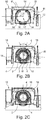
- the retainer ring 10 is shown in Figs. 2A to 2C and Fig. 3 presenting an embodiment comprising a first rigid ring element 12 made from a rigid material and a second flexible ring element 13 made from a soft material and inwardly directed protrusions 11 extending with a first angle ⁇ in a circumferential direction and gaps 14 between adjacently arranged protrusions 11 which extend in a second angle ⁇ .
- the protrusions 11 are an integral part of the first rigid ring element 12.
- the second ring element 13 is made of a soft material.
- a rubber-like soft plastic polymer, elastomer or rubber material
- the protrusions 11 of the retainer ring 10 are in contact with the protrusions 4 of the camera module 1 and are loaded with clamping forces.
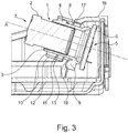
- Figs. 2B to 2C and Fig. 3 show the imaging system with a camera housing part 16 and the camera module 1 attached thereto.
- the camera module 1 is arranged in an opening 17 of the attachment wall 18 and fixed by a retainer ring 10 like described in the following.
- the camera module 1 is inserted with the lens objective 2 in a first step from the back side of the mounting surface 18 into the opening 17 of the camera module 1 and the retainer ring 10.
- the retainer ring 10 comprises a first rigid element 12 and radially inwardly directed protrusions 11 which are arranged in angles of 120 degrees with respect to each other related to a length axis A of the camera module 1.
- the protrusions 11 of the retainer ring 10 extend in a circumferential direction in a first angle ⁇ providing gaps 14 extending in a circumferential direction in a second angle ⁇ .
- the protrusions 4 of the camera module 1 are arranged in angles of 120 degrees with respect to each other related to a length axis A of the camera module 1 and extend in a circumferential direction in a third angle ⁇ ' providing gaps 15 extending in a circumferential direction in a fourth angle ⁇ '.
- the angles are adapted in a way that the first angles ⁇ are smaller than the fourth angles ⁇ ', and the third angles ⁇ ' are smaller than the second angles ⁇ .
- protrusions 4 of the camera module 1 fit through gaps 14 of the retainer ring 10
- protrusions 11 of the retainer ring 10 fit through gaps 15 of the camera module 1 as indicated in Fig. 2B .
- This allows for a force- and contact-free throughput of the camera module.
- the protrusions 11 of the retainer ring 10 are positioned behind the back surface of the protrusions 4 of the camera module 1.
- the thickness of the retainer ring 10 or of the protrusions 11 in the direction of the length axis A is designed so that the thickness of the protrusions 11 of the retainer ring 10 including the thickness of the flexible second ring element 13 is approximately identical or slightly greater than the distance between the attachment wall 18 of the camera housing part 16 and the back surface of the protrusions 4 of the camera module 1 facing towards the attachment wall 18 like shown in Fig. 3 . Therefore, the second ring element 13 is loaded by a pressure when the camera module 1 is fixed in the attachment position by the retainer ring 10 to tighten and seal the opening 17 of the camera housing part 16.
- the protrusions 4 of the camera module 1 are designed with conical surface with in axial direction towards the camera housing part 16 increasing thickness. Other geometries may also be possible.
- centering surfaces 9 may be provided, so that the camera module 1 may dive with the centering surfaces 9 into recesses 19 provided at the camera housing part 16, to a predetermined position in axial as well as in circumferential direction like shown in Figure 3 .
- the centering surfaces 9 are pressed into the corresponding recesses 19 and the protrusions 4 of the camera module are pressed with their end faces against the protrusions 11 of the retainer ring 10 and the retainer ring 10 finally against the attachment wall 18 of the camera housing part 16, so that the camera module 1 is attached to the camera housing part 16 by clamping.
- the mounting process of the camera module 1 is therefore reduced to only two steps, inserting of the camera module 1 into the opening 17 and the retainer ring 10, and rotating the retainer ring 10 to the attachment position. Since the image sensor is arranged in a fixed position with respect to the lens holder 3 and the lens objective 2 is also fixed at the lens holder 3, the lens objective 2 got an orientation and position relating to the image sensor which is independent from the mounting of the camera module 1 at the camera housing part 16.
- Fig. 4 an embodiment of the retainer ring 10 is described comprising a first rigid element 12, a first flexible element 13 and a second rigid element 20.
- the first flexible element 13 is arranged between the first rigid element 12 and the second rigid element 20, and the second rigid element 13 is facing towards the attachment wall 18 of the camera housing part 16 when the retainer ring 10 is in the attachment position.
- the second rigid element 20 will cause less friction during rotation of the retainer ring 10 to the attachment position.
- the first rigid element 12 and the second rigid element 20 are connected by connection elements 21.
- the rigid elements 12, 20 are therefore fixed to each other and the connection elements 21 prevent twisting. Production is also facilitated since the rigid elements 12, 20, including the connection elements 21, may be produced as an integral part, e.g. by injection molding.
- connection elements 21 are designed as thin legs and their length may be adapted to the distance between the outermost surface of the second rigid element 20 facing towards the attachment wall 18 and the first rigid element 12. This distance resembles to the distance between the protrusions 4 of the camera module 1 and the attachment wall 16 in order to establish a clamping. Therefore, the connection elements 21 are elastically deformable since they must imitate the compression and release movement of the flexible element 13 when pushing the retainer ring 10 to the attachment wall 18 and rotating it to the attachment position. Therefore, the connection elements 21 may be provided with e.g. weakened sections in order to adapt the distance in the attachment position.
Landscapes
- Physics & Mathematics (AREA)
- General Physics & Mathematics (AREA)
- Studio Devices (AREA)
Priority Applications (1)
| Application Number | Priority Date | Filing Date | Title |
|---|---|---|---|
| EP17161818.4A EP3379331B1 (de) | 2017-03-20 | 2017-03-20 | Bildgebungssystem für ein kraftfahrzeug |
Applications Claiming Priority (1)
| Application Number | Priority Date | Filing Date | Title |
|---|---|---|---|
| EP17161818.4A EP3379331B1 (de) | 2017-03-20 | 2017-03-20 | Bildgebungssystem für ein kraftfahrzeug |
Publications (2)
| Publication Number | Publication Date |
|---|---|
| EP3379331A1 true EP3379331A1 (de) | 2018-09-26 |
| EP3379331B1 EP3379331B1 (de) | 2020-10-14 |
Family
ID=58401398
Family Applications (1)
| Application Number | Title | Priority Date | Filing Date |
|---|---|---|---|
| EP17161818.4A Active EP3379331B1 (de) | 2017-03-20 | 2017-03-20 | Bildgebungssystem für ein kraftfahrzeug |
Country Status (1)
| Country | Link |
|---|---|
| EP (1) | EP3379331B1 (de) |
Citations (6)
| Publication number | Priority date | Publication date | Assignee | Title |
|---|---|---|---|---|
| US20060291068A1 (en) * | 2005-06-24 | 2006-12-28 | Jan Dahmen | Eyepiece unit for endoscopes |
| US20070264002A1 (en) * | 2006-05-11 | 2007-11-15 | Jin Ho Lee | Camera Module and Mobile Terminal Having the Same |
| DE102012210818A1 (de) * | 2012-06-26 | 2014-01-02 | Robert Bosch Gmbh | Kameramodul für ein Fahrzeug und Verfahren zu dessen Herstellung |
| US20150002737A1 (en) * | 2013-06-28 | 2015-01-01 | Robert Bosch Gmbh | Imager module for a camera, camera and method for manufacturing the imager module |
| WO2015032512A1 (en) * | 2013-09-03 | 2015-03-12 | Autoliv Development Ab | Camera module for a motor vehicle and method of mounting a camera module |
| EP2942939A1 (de) | 2014-05-07 | 2015-11-11 | Autoliv Development AB | Abbildungssystem für ein Kraftfahrzeug und Verfahren zur Montage eines Abbildungssystems |
-
2017
- 2017-03-20 EP EP17161818.4A patent/EP3379331B1/de active Active
Patent Citations (6)
| Publication number | Priority date | Publication date | Assignee | Title |
|---|---|---|---|---|
| US20060291068A1 (en) * | 2005-06-24 | 2006-12-28 | Jan Dahmen | Eyepiece unit for endoscopes |
| US20070264002A1 (en) * | 2006-05-11 | 2007-11-15 | Jin Ho Lee | Camera Module and Mobile Terminal Having the Same |
| DE102012210818A1 (de) * | 2012-06-26 | 2014-01-02 | Robert Bosch Gmbh | Kameramodul für ein Fahrzeug und Verfahren zu dessen Herstellung |
| US20150002737A1 (en) * | 2013-06-28 | 2015-01-01 | Robert Bosch Gmbh | Imager module for a camera, camera and method for manufacturing the imager module |
| WO2015032512A1 (en) * | 2013-09-03 | 2015-03-12 | Autoliv Development Ab | Camera module for a motor vehicle and method of mounting a camera module |
| EP2942939A1 (de) | 2014-05-07 | 2015-11-11 | Autoliv Development AB | Abbildungssystem für ein Kraftfahrzeug und Verfahren zur Montage eines Abbildungssystems |
Also Published As
| Publication number | Publication date |
|---|---|
| EP3379331B1 (de) | 2020-10-14 |
Similar Documents
| Publication | Publication Date | Title |
|---|---|---|
| AU2011214879B2 (en) | Connection device for a plastic tube | |
| US9407802B2 (en) | Imaging apparatus | |
| CN110651129A (zh) | 调节元件和用于部件的调节方法 | |
| US12038033B2 (en) | Angle coupling | |
| CN104094148B (zh) | 监视照相机用透镜装置 | |
| US10637188B2 (en) | Electrical plug connector | |
| US20160069364A1 (en) | Captured fastener device | |
| US20060078241A1 (en) | Bearing element | |
| EP3378704B1 (de) | Abbildungssystem für ein kraftfahrzeug | |
| WO2020219617A1 (en) | Holding element for holding a component to be secured, and holding system with such an element | |
| US20050078010A1 (en) | Sensor device and method for arranging a sensor device on a mounting plate | |
| EP3379331B1 (de) | Bildgebungssystem für ein kraftfahrzeug | |
| US6384501B2 (en) | Self-centering timing disk hub and method of mounting the same | |
| EP1795425A2 (de) | Einstellmechanismus für eine Lenksäule | |
| US11280361B2 (en) | Fastening device, a component comprising the fastening device, and method for pre-assembling the fastening device | |
| CN111033079A (zh) | 索环 | |
| EP3379330B1 (de) | Bildgebungssystem für ein kraftfahrzeug | |
| US12331779B2 (en) | Joining arrangement having a receiver and a ball joint | |
| KR101081763B1 (ko) | 차량용 윈드실드 와이퍼 장치 | |
| EP3029364A1 (de) | Einstellbare befestigungsschelle für einen lufteinlasskanal eines verbrennungsmotors eines kraftfahrzeugs | |
| US12247608B2 (en) | Connecting element, first component with the connecting element, connection structure using the connecting element, production method for the connecting element and respective connecting method | |
| EP2085130A1 (de) | Rückhaltevorrichtung | |
| US6768597B2 (en) | Mount for optical elements | |
| US20170328386A1 (en) | Rod End Cover | |
| JP3246941U (ja) | バッテリーターミナルのためのアダプタリング及びバッテリーターミナル |
Legal Events
| Date | Code | Title | Description |
|---|---|---|---|
| PUAI | Public reference made under article 153(3) epc to a published international application that has entered the european phase |
Free format text: ORIGINAL CODE: 0009012 |
|
| STAA | Information on the status of an ep patent application or granted ep patent |
Free format text: STATUS: THE APPLICATION HAS BEEN PUBLISHED |
|
| AK | Designated contracting states |
Kind code of ref document: A1 Designated state(s): AL AT BE BG CH CY CZ DE DK EE ES FI FR GB GR HR HU IE IS IT LI LT LU LV MC MK MT NL NO PL PT RO RS SE SI SK SM TR |
|
| AX | Request for extension of the european patent |
Extension state: BA ME |
|
| STAA | Information on the status of an ep patent application or granted ep patent |
Free format text: STATUS: REQUEST FOR EXAMINATION WAS MADE |
|
| 17P | Request for examination filed |
Effective date: 20190325 |
|
| RBV | Designated contracting states (corrected) |
Designated state(s): AL AT BE BG CH CY CZ DE DK EE ES FI FR GB GR HR HU IE IS IT LI LT LU LV MC MK MT NL NO PL PT RO RS SE SI SK SM TR |
|
| GRAP | Despatch of communication of intention to grant a patent |
Free format text: ORIGINAL CODE: EPIDOSNIGR1 |
|
| STAA | Information on the status of an ep patent application or granted ep patent |
Free format text: STATUS: GRANT OF PATENT IS INTENDED |
|
| INTG | Intention to grant announced |
Effective date: 20200506 |
|
| GRAS | Grant fee paid |
Free format text: ORIGINAL CODE: EPIDOSNIGR3 |
|
| GRAA | (expected) grant |
Free format text: ORIGINAL CODE: 0009210 |
|
| STAA | Information on the status of an ep patent application or granted ep patent |
Free format text: STATUS: THE PATENT HAS BEEN GRANTED |
|
| AK | Designated contracting states |
Kind code of ref document: B1 Designated state(s): AL AT BE BG CH CY CZ DE DK EE ES FI FR GB GR HR HU IE IS IT LI LT LU LV MC MK MT NL NO PL PT RO RS SE SI SK SM TR |
|
| REG | Reference to a national code |
Ref country code: GB Ref legal event code: FG4D |
|
| REG | Reference to a national code |
Ref country code: AT Ref legal event code: REF Ref document number: 1324167 Country of ref document: AT Kind code of ref document: T Effective date: 20201015 Ref country code: CH Ref legal event code: EP |
|
| REG | Reference to a national code |
Ref country code: DE Ref legal event code: R096 Ref document number: 602017025277 Country of ref document: DE |
|
| REG | Reference to a national code |
Ref country code: IE Ref legal event code: FG4D |
|
| REG | Reference to a national code |
Ref country code: AT Ref legal event code: MK05 Ref document number: 1324167 Country of ref document: AT Kind code of ref document: T Effective date: 20201014 |
|
| REG | Reference to a national code |
Ref country code: NL Ref legal event code: MP Effective date: 20201014 |
|
| PG25 | Lapsed in a contracting state [announced via postgrant information from national office to epo] |
Ref country code: PT Free format text: LAPSE BECAUSE OF FAILURE TO SUBMIT A TRANSLATION OF THE DESCRIPTION OR TO PAY THE FEE WITHIN THE PRESCRIBED TIME-LIMIT Effective date: 20210215 Ref country code: RS Free format text: LAPSE BECAUSE OF FAILURE TO SUBMIT A TRANSLATION OF THE DESCRIPTION OR TO PAY THE FEE WITHIN THE PRESCRIBED TIME-LIMIT Effective date: 20201014 Ref country code: NO Free format text: LAPSE BECAUSE OF FAILURE TO SUBMIT A TRANSLATION OF THE DESCRIPTION OR TO PAY THE FEE WITHIN THE PRESCRIBED TIME-LIMIT Effective date: 20210114 Ref country code: GR Free format text: LAPSE BECAUSE OF FAILURE TO SUBMIT A TRANSLATION OF THE DESCRIPTION OR TO PAY THE FEE WITHIN THE PRESCRIBED TIME-LIMIT Effective date: 20210115 Ref country code: FI Free format text: LAPSE BECAUSE OF FAILURE TO SUBMIT A TRANSLATION OF THE DESCRIPTION OR TO PAY THE FEE WITHIN THE PRESCRIBED TIME-LIMIT Effective date: 20201014 |
|
| REG | Reference to a national code |
Ref country code: LT Ref legal event code: MG4D |
|
| PG25 | Lapsed in a contracting state [announced via postgrant information from national office to epo] |
Ref country code: ES Free format text: LAPSE BECAUSE OF FAILURE TO SUBMIT A TRANSLATION OF THE DESCRIPTION OR TO PAY THE FEE WITHIN THE PRESCRIBED TIME-LIMIT Effective date: 20201014 Ref country code: AT Free format text: LAPSE BECAUSE OF FAILURE TO SUBMIT A TRANSLATION OF THE DESCRIPTION OR TO PAY THE FEE WITHIN THE PRESCRIBED TIME-LIMIT Effective date: 20201014 Ref country code: BG Free format text: LAPSE BECAUSE OF FAILURE TO SUBMIT A TRANSLATION OF THE DESCRIPTION OR TO PAY THE FEE WITHIN THE PRESCRIBED TIME-LIMIT Effective date: 20210114 Ref country code: LV Free format text: LAPSE BECAUSE OF FAILURE TO SUBMIT A TRANSLATION OF THE DESCRIPTION OR TO PAY THE FEE WITHIN THE PRESCRIBED TIME-LIMIT Effective date: 20201014 Ref country code: PL Free format text: LAPSE BECAUSE OF FAILURE TO SUBMIT A TRANSLATION OF THE DESCRIPTION OR TO PAY THE FEE WITHIN THE PRESCRIBED TIME-LIMIT Effective date: 20201014 Ref country code: IS Free format text: LAPSE BECAUSE OF FAILURE TO SUBMIT A TRANSLATION OF THE DESCRIPTION OR TO PAY THE FEE WITHIN THE PRESCRIBED TIME-LIMIT Effective date: 20210214 Ref country code: SE Free format text: LAPSE BECAUSE OF FAILURE TO SUBMIT A TRANSLATION OF THE DESCRIPTION OR TO PAY THE FEE WITHIN THE PRESCRIBED TIME-LIMIT Effective date: 20201014 |
|
| PG25 | Lapsed in a contracting state [announced via postgrant information from national office to epo] |
Ref country code: HR Free format text: LAPSE BECAUSE OF FAILURE TO SUBMIT A TRANSLATION OF THE DESCRIPTION OR TO PAY THE FEE WITHIN THE PRESCRIBED TIME-LIMIT Effective date: 20201014 Ref country code: NL Free format text: LAPSE BECAUSE OF FAILURE TO SUBMIT A TRANSLATION OF THE DESCRIPTION OR TO PAY THE FEE WITHIN THE PRESCRIBED TIME-LIMIT Effective date: 20201014 |
|
| REG | Reference to a national code |
Ref country code: DE Ref legal event code: R097 Ref document number: 602017025277 Country of ref document: DE |
|
| PG25 | Lapsed in a contracting state [announced via postgrant information from national office to epo] |
Ref country code: RO Free format text: LAPSE BECAUSE OF FAILURE TO SUBMIT A TRANSLATION OF THE DESCRIPTION OR TO PAY THE FEE WITHIN THE PRESCRIBED TIME-LIMIT Effective date: 20201014 Ref country code: SK Free format text: LAPSE BECAUSE OF FAILURE TO SUBMIT A TRANSLATION OF THE DESCRIPTION OR TO PAY THE FEE WITHIN THE PRESCRIBED TIME-LIMIT Effective date: 20201014 Ref country code: EE Free format text: LAPSE BECAUSE OF FAILURE TO SUBMIT A TRANSLATION OF THE DESCRIPTION OR TO PAY THE FEE WITHIN THE PRESCRIBED TIME-LIMIT Effective date: 20201014 Ref country code: CZ Free format text: LAPSE BECAUSE OF FAILURE TO SUBMIT A TRANSLATION OF THE DESCRIPTION OR TO PAY THE FEE WITHIN THE PRESCRIBED TIME-LIMIT Effective date: 20201014 Ref country code: SM Free format text: LAPSE BECAUSE OF FAILURE TO SUBMIT A TRANSLATION OF THE DESCRIPTION OR TO PAY THE FEE WITHIN THE PRESCRIBED TIME-LIMIT Effective date: 20201014 Ref country code: LT Free format text: LAPSE BECAUSE OF FAILURE TO SUBMIT A TRANSLATION OF THE DESCRIPTION OR TO PAY THE FEE WITHIN THE PRESCRIBED TIME-LIMIT Effective date: 20201014 |
|
| PLBE | No opposition filed within time limit |
Free format text: ORIGINAL CODE: 0009261 |
|
| STAA | Information on the status of an ep patent application or granted ep patent |
Free format text: STATUS: NO OPPOSITION FILED WITHIN TIME LIMIT |
|
| PG25 | Lapsed in a contracting state [announced via postgrant information from national office to epo] |
Ref country code: DK Free format text: LAPSE BECAUSE OF FAILURE TO SUBMIT A TRANSLATION OF THE DESCRIPTION OR TO PAY THE FEE WITHIN THE PRESCRIBED TIME-LIMIT Effective date: 20201014 |
|
| 26N | No opposition filed |
Effective date: 20210715 |
|
| PG25 | Lapsed in a contracting state [announced via postgrant information from national office to epo] |
Ref country code: AL Free format text: LAPSE BECAUSE OF FAILURE TO SUBMIT A TRANSLATION OF THE DESCRIPTION OR TO PAY THE FEE WITHIN THE PRESCRIBED TIME-LIMIT Effective date: 20201014 Ref country code: MC Free format text: LAPSE BECAUSE OF FAILURE TO SUBMIT A TRANSLATION OF THE DESCRIPTION OR TO PAY THE FEE WITHIN THE PRESCRIBED TIME-LIMIT Effective date: 20201014 Ref country code: IT Free format text: LAPSE BECAUSE OF FAILURE TO SUBMIT A TRANSLATION OF THE DESCRIPTION OR TO PAY THE FEE WITHIN THE PRESCRIBED TIME-LIMIT Effective date: 20201014 |
|
| REG | Reference to a national code |
Ref country code: CH Ref legal event code: PL |
|
| GBPC | Gb: european patent ceased through non-payment of renewal fee |
Effective date: 20210320 |
|
| PG25 | Lapsed in a contracting state [announced via postgrant information from national office to epo] |
Ref country code: SI Free format text: LAPSE BECAUSE OF FAILURE TO SUBMIT A TRANSLATION OF THE DESCRIPTION OR TO PAY THE FEE WITHIN THE PRESCRIBED TIME-LIMIT Effective date: 20201014 |
|
| REG | Reference to a national code |
Ref country code: BE Ref legal event code: MM Effective date: 20210331 |
|
| PG25 | Lapsed in a contracting state [announced via postgrant information from national office to epo] |
Ref country code: IE Free format text: LAPSE BECAUSE OF NON-PAYMENT OF DUE FEES Effective date: 20210320 Ref country code: GB Free format text: LAPSE BECAUSE OF NON-PAYMENT OF DUE FEES Effective date: 20210320 Ref country code: LI Free format text: LAPSE BECAUSE OF NON-PAYMENT OF DUE FEES Effective date: 20210331 Ref country code: LU Free format text: LAPSE BECAUSE OF NON-PAYMENT OF DUE FEES Effective date: 20210320 Ref country code: CH Free format text: LAPSE BECAUSE OF NON-PAYMENT OF DUE FEES Effective date: 20210331 |
|
| PG25 | Lapsed in a contracting state [announced via postgrant information from national office to epo] |
Ref country code: IS Free format text: LAPSE BECAUSE OF FAILURE TO SUBMIT A TRANSLATION OF THE DESCRIPTION OR TO PAY THE FEE WITHIN THE PRESCRIBED TIME-LIMIT Effective date: 20210214 |
|
| PG25 | Lapsed in a contracting state [announced via postgrant information from national office to epo] |
Ref country code: BE Free format text: LAPSE BECAUSE OF NON-PAYMENT OF DUE FEES Effective date: 20210331 |
|
| PG25 | Lapsed in a contracting state [announced via postgrant information from national office to epo] |
Ref country code: CY Free format text: LAPSE BECAUSE OF FAILURE TO SUBMIT A TRANSLATION OF THE DESCRIPTION OR TO PAY THE FEE WITHIN THE PRESCRIBED TIME-LIMIT Effective date: 20201014 |
|
| PG25 | Lapsed in a contracting state [announced via postgrant information from national office to epo] |
Ref country code: HU Free format text: LAPSE BECAUSE OF FAILURE TO SUBMIT A TRANSLATION OF THE DESCRIPTION OR TO PAY THE FEE WITHIN THE PRESCRIBED TIME-LIMIT; INVALID AB INITIO Effective date: 20170320 |
|
| REG | Reference to a national code |
Ref country code: DE Ref legal event code: R081 Ref document number: 602017025277 Country of ref document: DE Owner name: MAGNA ELECTRONICS SWEDEN AB, SE Free format text: FORMER OWNER: VEONEER SWEDEN AB, VARGARDA, SE |
|
| PG25 | Lapsed in a contracting state [announced via postgrant information from national office to epo] |
Ref country code: MK Free format text: LAPSE BECAUSE OF FAILURE TO SUBMIT A TRANSLATION OF THE DESCRIPTION OR TO PAY THE FEE WITHIN THE PRESCRIBED TIME-LIMIT Effective date: 20201014 |
|
| PG25 | Lapsed in a contracting state [announced via postgrant information from national office to epo] |
Ref country code: MT Free format text: LAPSE BECAUSE OF FAILURE TO SUBMIT A TRANSLATION OF THE DESCRIPTION OR TO PAY THE FEE WITHIN THE PRESCRIBED TIME-LIMIT Effective date: 20201014 |
|
| PG25 | Lapsed in a contracting state [announced via postgrant information from national office to epo] |
Ref country code: TR Free format text: LAPSE BECAUSE OF FAILURE TO SUBMIT A TRANSLATION OF THE DESCRIPTION OR TO PAY THE FEE WITHIN THE PRESCRIBED TIME-LIMIT Effective date: 20201014 |
|
| PGFP | Annual fee paid to national office [announced via postgrant information from national office to epo] |
Ref country code: DE Payment date: 20260320 Year of fee payment: 10 |
|
| PGFP | Annual fee paid to national office [announced via postgrant information from national office to epo] |
Ref country code: FR Payment date: 20260324 Year of fee payment: 10 |