EP3379158A1 - Method for operating a heat pump system - Google Patents
Method for operating a heat pump system Download PDFInfo
- Publication number
- EP3379158A1 EP3379158A1 EP17162847.2A EP17162847A EP3379158A1 EP 3379158 A1 EP3379158 A1 EP 3379158A1 EP 17162847 A EP17162847 A EP 17162847A EP 3379158 A1 EP3379158 A1 EP 3379158A1
- Authority
- EP
- European Patent Office
- Prior art keywords
- medium
- temperature
- heat
- heat pump
- mover
- Prior art date
- Legal status (The legal status is an assumption and is not a legal conclusion. Google has not performed a legal analysis and makes no representation as to the accuracy of the status listed.)
- Granted
Links
Images




Classifications
-
- F—MECHANICAL ENGINEERING; LIGHTING; HEATING; WEAPONS; BLASTING
- F25—REFRIGERATION OR COOLING; COMBINED HEATING AND REFRIGERATION SYSTEMS; HEAT PUMP SYSTEMS; MANUFACTURE OR STORAGE OF ICE; LIQUEFACTION SOLIDIFICATION OF GASES
- F25B—REFRIGERATION MACHINES, PLANTS OR SYSTEMS; COMBINED HEATING AND REFRIGERATION SYSTEMS; HEAT PUMP SYSTEMS
- F25B49/00—Arrangement or mounting of control or safety devices
- F25B49/02—Arrangement or mounting of control or safety devices for compression type machines, plants or systems
-
- F—MECHANICAL ENGINEERING; LIGHTING; HEATING; WEAPONS; BLASTING
- F24—HEATING; RANGES; VENTILATING
- F24F—AIR-CONDITIONING; AIR-HUMIDIFICATION; VENTILATION; USE OF AIR CURRENTS FOR SCREENING
- F24F11/00—Control or safety arrangements
- F24F11/70—Control systems characterised by their outputs; Constructional details thereof
- F24F11/80—Control systems characterised by their outputs; Constructional details thereof for controlling the temperature of the supplied air
- F24F11/83—Control systems characterised by their outputs; Constructional details thereof for controlling the temperature of the supplied air by controlling the supply of heat-exchange fluids to heat-exchangers
-
- F—MECHANICAL ENGINEERING; LIGHTING; HEATING; WEAPONS; BLASTING
- F24—HEATING; RANGES; VENTILATING
- F24F—AIR-CONDITIONING; AIR-HUMIDIFICATION; VENTILATION; USE OF AIR CURRENTS FOR SCREENING
- F24F11/00—Control or safety arrangements
- F24F11/70—Control systems characterised by their outputs; Constructional details thereof
- F24F11/72—Control systems characterised by their outputs; Constructional details thereof for controlling the supply of treated air, e.g. its pressure
- F24F11/74—Control systems characterised by their outputs; Constructional details thereof for controlling the supply of treated air, e.g. its pressure for controlling air flow rate or air velocity
- F24F11/76—Control systems characterised by their outputs; Constructional details thereof for controlling the supply of treated air, e.g. its pressure for controlling air flow rate or air velocity by means responsive to temperature, e.g. bimetal springs
Definitions
- the invention relates to a method for operating a heat pump system wherein an operation of a heat pump is controlled taking into account an operation state of a medium mover as for example a fan.
- the operation state of the medium mover is determined based on a measurement of a thermodynamic quantity.
- the capacity control of a heating/cooling emitter and the control of a heat source are separated.
- the state of operation of the emitter is therefore usually unknown to the heat source or the heat pump supplying heat to the emitter.
- a fan coil unit as an example of an emitter, such unit has two thermostats wherein one is an air temperature thermostat measuring a room temperature and the other is a water temperature thermostat or more general a heat transport medium temperature thermostat to prevent providing cold air for heating and hot air for cooling.
- the heat pump system usually has a room temperature sensor which is at some distance from the emitter and which is read out by a controller of the heat pump system.
- the air temperature thermostat works in order to start the fan when the air temperature goes down to a lower threshold and to stop the fan when the air temperature goes up to a higher threshold in a case of a heating operation and the other way round in a cooling operation.
- the water temperature thermostat (the heat transport medium temperature thermostat) works in order to start the fan when the water flow temperature or heat transport medium flow temperature goes up higher than a threshold in case of heating and goes down lower than a threshold in case of cooling.
- the heat transfer efficiency of a fan coil unit that is the efficiency of the transfer of heat between the heat transport medium and the space to be heated or cooled, is very low when the fan is stopped. This causes an increase of power consumption of the heat pump.
- the energy efficiency of the heat pump is higher at lower temperatures of the water flow temperature or the heat transport medium flow temperature in case of heating, and at higher temperatures in case of cooling.
- the water flow temperature or the heat transport medium flow temperature has to be raised to supply the same supplied heat in case of heating and lowered to remove the same removed heat in case of cooling. This causes a lower energy efficiency of the heat pump.
- the air temperature thermostat of the fan coil unit detects that the room temperature rises or drops to a target value earlier than the room thermostat read out by the controller of the heat pump because it detects the air temperature closer to the fan coil unit. Therefore, e. g. in the case of heating, when the air temperature thermostat of the fan coil unit detects that the room temperature rises to the target value, the room temperature detected by the thermostat of the heat pump (which is read out by the controller) is still lower than the threshold to stop the heat pump. Similarly, in the case of operation of cooling the room, the room temperature detected by the thermostat of the heat pump would still be higher than the threshold to stop the heat pump.
- Figure 2 shows the general behaviour of a heat pump system being controlled conventionally.
- Figure 2 in the first diagram shows the room temperature over time
- in the second diagram the flow temperature of the heat transport medium over time
- in the third diagram the fan operation over time and in the lowest diagram the heat pump operation over time.
- an upper threshold and a lower threshold for the operation of the fan are indicated as dashed lines.
- a target room temperature is indicated as dashed line between the upper and the lower threshold of the fan operation.
- Vertical dashed lines indicate corresponding points in time in the first, second and third diagram.
- the water flow temperature to supply sufficient heat to keep the room temperature is changed by the ambient temperature and the target room temperature.
- the target flow temperature can be lower.
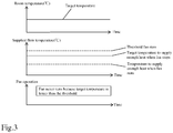
- Fig. 3 shows the conventional operation behaviour of the general water temperature thermostat in conventional control methods.
- the upper-most diagram of Fig. 3 shows the room temperature over time
- the middle diagram of Fig. 3 shows the supplied flow temperature of the heat transport medium over time
- the lower most diagram shows the fan operation over time.
- the invention relates to a method for operating a heat pump system.
- the heat pump system can be used for heating a medium or for cooling a medium.
- the inventive idea applies to both cases, however, the description shall be made separately here.
- the heat pump system operated in the method according to the invention comprises a heat pump and a heat emitter.
- the heat emitter comprises a heat exchanger which is configured to exchange heat between a heat transport medium and the medium to be heated.
- the heat emitter further comprises at least one medium mover for effecting a flow of the medium over the heat exchanger.
- the medium mover may for example be a fan or an array of fans. However, also other suitable means for effecting said flow of the medium to be heated or cooled over the heat exchanger can be employed.
- the heat transport medium may for example be water and the medium to be heated or cooled may for example be air in a room to be heated or cooled.
- the temperature of the medium to be heated or cooled may for example be a room temperature. If reference is made to a medium the medium to be heated or cooled is meant. If reference is made to the heat transport medium, the medium flowing between the heat pump and the heat emitter is meant.
- the heat pump and the heat emitter are controlled separately.
- the operation of the medium mover is usually stopped when the temperature of the medium to be heated as measured by a thermostat at the emitter reaches an upper threshold which here shall be referred to as upper medium mover threshold.
- the operation of the medium mover is usually started when the temperature of the medium to be heated as measured at the emitter reaches a lower threshold which shall be referred to as lower medium mover threshold here.
- the temperature of the medium based on which the medium mover is stopped or started is measured by a thermostat which is mounted at the heat emitter.
- the heat pump is controlled to raise the temperature of the heat transport medium if the temperature of the medium to be heated is below a target medium temperature.
- the temperature based on which the heat pump is controlled is measured by a different thermostat than the temperature based on which the medium mover is stopped or started.
- the thermostat used to measure the temperature of the medium to be heated, based on which the heat pump is controlled has a greater distance from the heat emitter than the thermostat with which the temperature is controlled based on which the medium mover is stopped or started.
- thermodynamic quantity measuring step At least one thermodynamic quantity is measured in the heat pump system in a step, which is here referred to as thermodynamic quantity measuring step.
- the thermodynamic quantity includes at least one of a measured temperature of the medium to be heated, which is preferably measured by the thermostat used to control the heat pump, and/or a measured return flow temperature of the heat transport medium and/or a measured supplied heat.
- the at least one measured temperature of the medium to be heated is preferably measured by the temperature sensor based on which the heat pump is controlled.
- This temperature may for example be the room temperature of a room to be heated.
- a return flow temperature of the heat transport medium is usually the temperature which the heat transport medium has after flowing out of the heat emitter.
- the measured supplied heat is usually for example the amount of heat which is exchanged in the heat emitter in a certain amount of time.
- the method for operating a heat pump system comprises a determining step in which it is determined based on the thermodynamic quantity measured in the thermodynamic quantity measuring step whether the medium mover is operating.
- the heat pump is controlled to stop rising the temperature of the heat transport medium when it is determined in said determining step that the medium mover is not operating. This will allow the temperature of the medium to be heated to reach the lower medium mover threshold so that the medium mover is started. It is ensured that the heat pump system does not permanently operate in the above described inefficient state where the heat pump raises the temperature of the heat transport medium while the medium mover is stopped. The efficiency of the heat pump system is therefore increased compared to the prior art.
- the measurements of the thermodynamic quantity obtained in the thermodynamic quantity measuring step can be used to determine a change rate per time of the thermodynamic quantity. It can then be determined in the determining step that the medium mover is stopped if the thermodynamic quantity drops at a change rate per time which is lower than a first change rate threshold or raises at a change rate per time which is higher than a first change rate threshold.
- This embodiment is based on the insight that e. g. the room temperature drops and the supplied heat decreases quickly when the fan stops and that e. g. the return flow temperature raises quickly if the fan stops.
- the change rate per time of the thermodynamic quantity can be determined based on the results of the thermodynamic quantity measuring step. It can then be determined in said determining step that the medium mover is operating if the thermodynamic quantity raises at a change rate per time which is higher than a second change rate threshold or drops at a change rate per time which is lower than a second change rate threshold.
- This embodiment uses the insight that the room temperature raises and the supplied heat increases quickly when the medium mover is operating, while the return flow temperature drops quickly if the medium mover is operating.
- the temperature of the heat transport medium can be measured and the medium mover is controlled not to operate when a temperature of the heat transport medium is below a transport medium threshold. This step ensures that when the medium mover operates the heat transport medium has a sufficient temperature to in fact cause the room to be heated. As long as the temperature of the heat transport medium is too low the medium mover should preferably not be operated.
- the heat pump may be stopped when it is detected that the medium mover is not operating.
- the heat pump may be started when the temperature of the medium to be heated, that is for example the room temperature, reaches a lower threshold which shall be referred to as lower heat pump threshold here. This avoids a situation where the heat pump is operating although the medium mover is not operating while the room temperature is sufficiently high.
- the heat pump may be controlled to lower the temperature of the heat transport medium if the temperature of the medium to be heated is above the target medium temperature. This further improves the efficiency of the heat pump system because the amount of heat supplied by the heat pump is reduced if the temperature of the medium to be heated is already above the target medium temperature.
- the present invention also relates to a method for operating a heat pump system for cooling a medium.
- this medium shall be addressed also as medium to be cooled.
- the heat pump system comprises a heat pump and an emitter which is here also addressed as cooling emitter.
- the cooling emitter may be technically the same as a heat emitter, however acting as a heat sink for the surrounding medium to be cooled.
- the cooling emitter comprises a heat exchanger for exchanging heat between the heat transport medium and the medium to be cooled.
- the heat transport medium may flow between the heat pump and the cooling emitter, preferably in a closed circuit.
- the cooling emitter according to the invention further comprises at least one medium mover for effecting a flow of the medium to be cooled over the heat exchanger. Anything said above with respect to the structure of the heat emitter, the heat transport medium and the heat pump is also valid here with respect to the method for cooling a medium.
- Common heat pump systems are controlled so that the operation of the medium mover is stopped when the temperature of the medium to be cooled as measured by a thermostat of the emitter reaches a lower medium mover threshold.
- the operation of the medium mover is started when the temperature of the medium to be cooled as measured by a thermostat of the emitter reaches an upper medium mover threshold.
- the heat pump is controlled to lower the temperature of the heat transport medium if the temperature of the medium to be cooled is above the target medium temperature.
- thermodynamic quantity is measured in the heat pump system in a thermodynamic quantity measuring step.
- the thermodynamic quantity may be a measured temperature of the medium to be cooled, preferably measured with a thermostat having a greater distance from the emitter than the thermostat of the emitter, and/or a measured return flow temperature of the heat transport medium and/or a measured removed heat.
- thermodynamic quantity Based on the measured thermodynamic quantity it can then be determined in a determining step whether the medium mover is operating or not.
- the heat pump according to the invention is controlled to stop lowering the temperature of the heat transport medium when it is determined in the determining step that the medium mover is not operating. Similarly as in the case of heating this allows the temperature of the medium to be cooled to reach the upper medium mover threshold so that the medium mover is started. It is therefore avoided that the medium to be cooled is kept below the upper medium mover threshold by excessive operation of the heat pump without the medium mover operating. The efficiency of the heat pump system is therefore increased.
- the change rate per time of the thermodynamic quantity may be determined based on the results of the thermodynamic quantity measuring step and it may be determined in the determining step that the medium mover is stopped if the thermodynamic quantity raises at a change rate per time which is higher than a first change rate threshold or drops at a change rate per time which is lower than a first change rate threshold. Whether a raising or dropping of the thermodynamic quantity is regarded here as in the case of heating depends on the thermodynamic quantity. The temperature of the medium to be cooled will raise if the medium mover is stopped. On the other hand the measured return flow temperature will drop and the measured removed heat will decrease if the medium mover is not operating.
- a change rate per time of the thermodynamic quantity measured in the thermodynamic quantity measuring step can be determined and it can be determined in the determining step that the medium mover is operating if the thermodynamic quantity drops at a change rate per time which is lower than a second change rate threshold or raises at a change rate per time which is higher than a second change rate threshold. Again, it depends on the chosen thermodynamic quantity whether it drops or raises when the medium mover is operating. The temperature of the medium to be cooled will drop when the medium mover is operating. On the other hand the measured return flow temperature of the heat transport medium will raise and the measured removed heat will increase if the medium mover is operating.
- the temperature of the heat transport medium can be measured and the medium mover does not operate when the temperature of the heat transport medium is above or equal a transport medium threshold. This ensures that the medium mover only operates when the temperature of the heat transport medium is sufficiently low to in fact effect a cooling on the medium to be cooled.
- the heat pump may be stopped when it is detected that the medium mover is not operating and the heat pump may be started when the temperature of the medium to be cooled reaches an upper heat pump threshold.
- the heat pump may be controlled to raise the temperature of the heat transport medium if the temperature of the medium to be cooled is below the target medium temperature. This further improves the efficiency of the heat pump system because the amount of heat removed by the heat pump is reduced if the temperature of the medium to be cooled is already below the target medium temperature.
- thermodynamic quantity measuring step is repeatedly carried out in predetermined time intervals. This allows a continuous operation of the heat pump system at optimized efficiency.
- Fig. 1 shows an example of a heat pump system, which is suitable for heating or cooling a medium as for example the air in a room.
- the heat pump system shown in Fig. 1 comprises a heat pump 1 and three heat emitters 2a, 2b, 2c.
- the heat emitters 2a, 2b, 2c are in this example fan coil units comprising a heat exchanger for exchanging heat between a heat transport medium and the medium to be heated or cooled.
- the heat emitters 2a, 2b, 2c are here always addressed as heat emitters regardless whether they transfer heat from the heat transport medium to the medium or from the medium to the heat transport medium.
- the heat emitters 2a, 2b, 2c furthermore each comprise at least one medium mover, as for example a fan, for effecting a flow of the medium over the heat exchanger.
- the fan coil units 2a, 2b, 2c each have an air temperature thermostat 3a, 3b, 3c and a water temperature thermostat.
- a room temperature sensor or room temperature thermostat 4 which is located at a greater distance to the heat exchangers of the fan coil units 2a, 2b, 2c than the temperature sensors 3a, 3b, 3c, measures the room temperature, that is the temperature of the medium to be heated or cooled.
- the heat pump 1 and the fan coil units 2a, 2b, 2c are connected with each other by a heat transport medium circuit 5 which may for example be a water circuit 5.
- the heat pump 1 comprises an evaporator 6 and a condenser 7 in the case of heating or a condenser 6 and an evaporator 7 in the case of cooling.
- a compressor 9 is arranged between the evaporator 6, 7 and condenser 7, 6 and an expansion valve 8 is arranged between the evaporator 6, 7 and the condenser 7, 6 on the opposite side.
- the expansion valve 8, the evaporator 6, 7, the compressor 9, and the condenser 7, 6 are arranged together in a refrigerant circuit 10.
- the condenser or evaporator 7 comprises a heat exchanger for exchanging heat between the refrigerant circuit 10 and the heat transport medium circuit 5.
- the heat transport medium e. g.
- the flow of the heat transport medium is effected by a circulation pump 11 which is arranged in the heat transport medium circuit 5.
- an optional tank 12 is shown the content of which can be heated by heat transport medium flowing in a coil 13 within the tank 12.
- the heat transport medium can be branched off the heat transport medium circuit 5 through a three-way valve 14.
- the conduit for feeding the coil 13 within the tank 12 bypasses the fan coil unit 2a, 2b, 2c.
- the heat transport medium circuit 5 comprises a heat transport medium temperature sensor 15 located directly before an entry into the heat pump 1, with which sensor 15 the return flow temperature of the heat transport medium can be measured.
- the example system shown in Fig. 1 further comprises a heat transport medium sensor 16 located directly behind an exit for the heat transport medium of the heat pump 1 with which the temperature of the supplied heat transport medium leaving the heat pump can be measured.
- the heat transport medium circuit 5 further comprises a flow rate sensor 19 located in the heat transport medium circuit 5 with which the flow rate of the heat transport medium can be measured. Such flow rate sensor 19 can be used to calculate the supplied or removed heat.
- the method for operating the heat pump system is controlled by a controller 17.
- the controller 17 receives a temperature measurement from the room temperature sensor 4, optionally the supply flow temperature sensor 16, the return flow temperature sensor 15 as well as optionally the temperature measurement from an ambient temperature sensor 18 located in the heat pump unit.
- the controller 17 further receives a flow rate measurement from the flow rate sensor 19.
- the controller 17 controls the heat pump unit as well as the circulation pump 11 based on the measurement from these sensors.
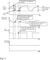
- Fig. 4 shows an operational behavior of the method for operating a heat pump system according to the invention.
- Fig. 4 shows the case of heating a room.
- the operation is analogue in the case of cooling a room, but with lower and upper thresholds inverted.
- the uppermost diagram shows the air temperature over time
- the second diagram shows the target flow temperature over time
- the third diagram shows the fan operation over time
- the lowermost diagram shows the heat pump operation over time.
- the raising of the temperature of the heat transport medium shown in the second diagram is therefore stopped. This results in the air temperature further decreasing until it reaches a lower medium mover threshold, indicated as lowermost dashed horizontal line in the first diagram of Fig. 4 .
- the air temperature reaching the lower medium mover threshold results in the fan being started, as can be seen in the third diagram.
- the air temperature or room temperature shown in the first diagram starts increasing again, although the target flow temperature has not changed.
- the quick raise of the air temperature can be detected according to the method of the present invention and can indicate that the fan is operating.
- the target flow temperature is allowed to be changed again and further increased at the time indicated by the rightmost vertical dashed line because the air temperature is still lower than the target room temperature in Fig. 4 .
- the increase of the target flow temperature is stopped and the target flow temperature is maintained constant.
- the air temperature in the room further increases which results in restarting the fan operation. If the air temperature is already higher than the target room temperature when the fan operation is detected, the target flow temperature is lowered as soon as the target flow temperature is allowed to be changed. As the air temperature reaches the uppermost medium mover threshold the fan is stopped again and the operation cycle starts again as explained above from the point where the fan stopped.
- the heat pump is operating all the time and the target flow temperature is adjusted.
- Fig. 5 shows an operation example wherein the heat pump may be stopped.
- the uppermost diagram of Fig. 5 shows the air temperature or room temperature
- the second diagram shows the supplied flow temperature
- the third diagram shows the fan operation
- the lowermost diagram shows the heat pump operation.
- the room temperature raises as shown in the uppermost diagram because the heat pump operates and the fan operates with excess supplied heat due to a higher target flow temperature than the supplied flow temperature, which amount of supplied heat is sufficient to keep room temperature to keep the fan running.
- the room temperature reaches the threshold to stop the fan, indicated as uppermost dashed horizontal line in the first diagram of Fig. 5 , the fan stops at the leftmost vertical dashed line.
- the air temperature drops quickly between the leftmost vertical dashed line and the second vertical dashed line.
- the quick drop of room temperature indicates according to the invention that the fan has stopped, so the heat pump operation is stopped at the second vertical dashed line.
- Fig. 6 shows an example flow diagram for the calculation of the target flow temperature.
- a controller can determine the target flow temperature based on the flow shown in Fig. 6 at certain control intervals as for example one minute.
- step S61 it is checked whether a time counter equals the permission check interval longer than the control interval which can detect the change of a thermodynamic quantity. If the time counter equals the permission check interval step S62 is carried out, where the permission status is checked indicating whether to change the target flow temperature. Step S62 is bypassed if step S61 determines that the time counter does not equal the permission check interval.
- step S63 It is afterwards checked in step S63 whether target flow temperature change is permitted based on the permission status determined in S62. If the target flow temperature change is not permitted the method ends and restarts at a later time.
- the target flow temperature is calculated in step S64.
- the calculation of the target flow temperature may for example use a characteristic as shown in Fig. 7 , showing the flow temperature as a function of the outdoor temperature.
- the target flow temperature may be adjusted to be raised if the air temperature is lower than the target room temperature or to be lowered if the air temperature is higher than the target room temperature. Either the above first calculation method using the function of the outdoor temperature or the above second calculation method using the function of the deviation between the air temperature and the target room temperature or a combined method of both calculation methods can be used.
- step S65 It is then determined in step S65 whether the target flow temperature is lower than the threshold of the water temperature thermostat, shown in the second diagram of figure 5 .
- step S66 is carried out in which the target flow temperature is set as the threshold of the water temperature thermostat. If in step S65 the decision is negative, the target flow temperature is set to the calculated value in step S67. The flow then ends and can be carried out again at a subsequent point in time.
- Fig. 8 is a flow diagram showing how the permission status to change the target flow temperature is checked in step S62 in Fig. 6 .
- the thermodynamic quantity to be measured is the room temperature or the temperature of the medium to be heated or cooled.
- step S82 It is then decided in step S82 whether ⁇ is equal or lower than the first change rate threshold (the sign is minus, for example -0.1°C/min). If this is the case, the change of the target flow temperature is stopped in step S83. If this is not the case, it is determined in step S84 whether ⁇ is equal or greater than a second change rate threshold (a sign is plus, for example +0.1°C/min). If this is the case, the change of the target flow temperature is permitted in step S85. If this is not the case, the current permission status is kept (S86). In case of cooling, plus/minus sign of these thresholds and the direction of inequality in step 82 and 84 are opposite.
- the first change rate threshold the sign is minus, for example -0.1°C/min
- the determination whether the fan is stopped or running can be based on different thermodynamic quantities measured in the heat pump system.
- the room temperature can be used as thermodynamic quantity.
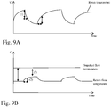
- Fig. 9A shows the room temperature over time.
- ⁇ Ta is exemplified by vertical arrows and ⁇ Ta is depicted as horizontal arrows.
- thermodynamic quantity which can be used for determining whether the fan is stopped or is running can be the return flow temperature which is the temperature of the heat transport medium after having flown through the heat emitter.
- the graphical representation of this method is shown in Fig. 9B at (2 ). If ⁇ is used instead of ⁇ in Fig. 8 , the sign of the first change rate threshold and the second change rate threshold and the direction of inequality of S82 and S84 are opposite. And in the case of cooling, plus/minus sign of these thresholds and the direction of inequality in step 82 and 84 are opposite to the case of heating.
- thermodynamic quantity to be used to detect whether the fan is stopped or is running can be the reduction of the supplied heat which occurs if the fan stops.
- ⁇ Q Q t ⁇ Q t ⁇ ⁇ tc
- Q t ⁇ Cp Fw / 60 * Tsup ⁇ Tret
- Q(t) is the supplied heat (e.g. in kW)
- ⁇ is the density of water
- Cp is the specific heat
- Fw is the flow rate in L/min
- Tsup is the supplied flow temperature
- Tret is the return flow temperature
- ⁇ tc is the calculation interval (for example 3 minutes).
- the behavior of the return flow temperature is shown in Fig. 9B .
- the supplied flow temperature is depicted as a constant horizontal line.
- the return flow temperature in the case of heating operation is lower and is depicted as the lower curve in Fig. 9B .
- the reduction of the supplied heat is indicated by the arrow (3) while the change of the return flow temperature described above is indicated by the arrows (2), wherein the horizontal arrow is the calculation interval ⁇ tb and the vertical arrow is the temperature change ⁇ Tb.
Landscapes
- Engineering & Computer Science (AREA)
- Mechanical Engineering (AREA)
- General Engineering & Computer Science (AREA)
- Physics & Mathematics (AREA)
- Chemical & Material Sciences (AREA)
- Combustion & Propulsion (AREA)
- Thermal Sciences (AREA)
- Fluid Mechanics (AREA)
- Air Conditioning Control Device (AREA)
Abstract
Description
- The invention relates to a method for operating a heat pump system wherein an operation of a heat pump is controlled taking into account an operation state of a medium mover as for example a fan. The operation state of the medium mover is determined based on a measurement of a thermodynamic quantity.
- In common heat pump systems the capacity control of a heating/cooling emitter and the control of a heat source are separated. The state of operation of the emitter is therefore usually unknown to the heat source or the heat pump supplying heat to the emitter. In case of a fan coil unit as an example of an emitter, such unit has two thermostats wherein one is an air temperature thermostat measuring a room temperature and the other is a water temperature thermostat or more general a heat transport medium temperature thermostat to prevent providing cold air for heating and hot air for cooling. Furthermore, the heat pump system usually has a room temperature sensor which is at some distance from the emitter and which is read out by a controller of the heat pump system.
- The air temperature thermostat works in order to start the fan when the air temperature goes down to a lower threshold and to stop the fan when the air temperature goes up to a higher threshold in a case of a heating operation and the other way round in a cooling operation.
- The water temperature thermostat (the heat transport medium temperature thermostat) works in order to start the fan when the water flow temperature or heat transport medium flow temperature goes up higher than a threshold in case of heating and goes down lower than a threshold in case of cooling.
- The heat transfer efficiency of a fan coil unit, that is the efficiency of the transfer of heat between the heat transport medium and the space to be heated or cooled, is very low when the fan is stopped. This causes an increase of power consumption of the heat pump.
- The energy efficiency of the heat pump is higher at lower temperatures of the water flow temperature or the heat transport medium flow temperature in case of heating, and at higher temperatures in case of cooling. When the fan is stopped, the water flow temperature or the heat transport medium flow temperature has to be raised to supply the same supplied heat in case of heating and lowered to remove the same removed heat in case of cooling. This causes a lower energy efficiency of the heat pump.
- Usually the air temperature thermostat of the fan coil unit detects that the room temperature rises or drops to a target value earlier than the room thermostat read out by the controller of the heat pump because it detects the air temperature closer to the fan coil unit. Therefore, e. g. in the case of heating, when the air temperature thermostat of the fan coil unit detects that the room temperature rises to the target value, the room temperature detected by the thermostat of the heat pump (which is read out by the controller) is still lower than the threshold to stop the heat pump. Similarly, in the case of operation of cooling the room, the room temperature detected by the thermostat of the heat pump would still be higher than the threshold to stop the heat pump.
- In the following, the problem of the conventional heat pump systems shall be described with reference to a heating operation. However, the problem exists in an analogous way for a cooling operation.
-
Figure 2 shows the general behaviour of a heat pump system being controlled conventionally.Figure 2 in the first diagram shows the room temperature over time, in the second diagram the flow temperature of the heat transport medium over time, in the third diagram the fan operation over time and in the lowest diagram the heat pump operation over time. In the uppermost diagram an upper threshold and a lower threshold for the operation of the fan are indicated as dashed lines. Furthermore, a target room temperature is indicated as dashed line between the upper and the lower threshold of the fan operation. Vertical dashed lines indicate corresponding points in time in the first, second and third diagram. - 1. In the beginning the room temperature raises due to the heating operation. At
point 1 the air temperature thermostat detects that the room temperature arrives at an upper threshold and stops the fan. However, the heat pump is still running. - 2. As the fan is stopped the room temperature goes down gradually because the heat transfer efficiency of the fan coil unit drops. In response to this the controller of the heat pump raises the target flow temperature to increase the supplied heat.
- 3. As a result of the raised target flow temperature of the heat transport medium the room temperature raises again. However, the fan will never restart because the room temperature is always kept higher than the threshold to restart the fan. The heat pump efficiency is therefore permanently lower than with a running fan.
- The water flow temperature to supply sufficient heat to keep the room temperature is changed by the ambient temperature and the target room temperature. When the heat load is small, the target flow temperature can be lower.
-
Fig. 3 shows the conventional operation behaviour of the general water temperature thermostat in conventional control methods. The upper-most diagram ofFig. 3 shows the room temperature over time, the middle diagram ofFig. 3 shows the supplied flow temperature of the heat transport medium over time and the lower most diagram shows the fan operation over time. - 1. When the heat load is small, the flow temperature required to supply enough heat is lower than the threshold if the fan can keep running.
- 2. However, due to above described control the fan never runs and the controller of the heat pump raises the target flow temperature of the heat transport medium to a higher value (full line) than the temperature which would be sufficient to supply enough heat if the fan runs (lower dashed line). Thus, in a conventional control the room temperature can be kept without the fan running, however, the efficiency of the heat pump is lower than when the fan runs.
- It is therefore the problem to be solved by the present invention to increase the efficiency of a heat pump system having a heat pump and a heat emitter with a medium mover as for example a fan, in which the heat pump and the heat emitter are controlled independently from each other.
- The problem is solved by the method according to
claim 1 and the method according toclaim 8. The corresponding dependent claims describe advantageous embodiment of the method according toclaim 1 and the method according toclaim 8. - The invention relates to a method for operating a heat pump system. The heat pump system can be used for heating a medium or for cooling a medium. The inventive idea applies to both cases, however, the description shall be made separately here.
- The heat pump system operated in the method according to the invention comprises a heat pump and a heat emitter. The heat emitter comprises a heat exchanger which is configured to exchange heat between a heat transport medium and the medium to be heated. The heat emitter further comprises at least one medium mover for effecting a flow of the medium over the heat exchanger. The medium mover may for example be a fan or an array of fans. However, also other suitable means for effecting said flow of the medium to be heated or cooled over the heat exchanger can be employed.
- Throughout this invention the heat transport medium may for example be water and the medium to be heated or cooled may for example be air in a room to be heated or cooled. The temperature of the medium to be heated or cooled may for example be a room temperature. If reference is made to a medium the medium to be heated or cooled is meant. If reference is made to the heat transport medium, the medium flowing between the heat pump and the heat emitter is meant.
- In common heat pump systems the heat pump and the heat emitter are controlled separately. The operation of the medium mover is usually stopped when the temperature of the medium to be heated as measured by a thermostat at the emitter reaches an upper threshold which here shall be referred to as upper medium mover threshold. The operation of the medium mover is usually started when the temperature of the medium to be heated as measured at the emitter reaches a lower threshold which shall be referred to as lower medium mover threshold here. Usually the temperature of the medium based on which the medium mover is stopped or started, is measured by a thermostat which is mounted at the heat emitter.
- In common heat pump systems the heat pump is controlled to raise the temperature of the heat transport medium if the temperature of the medium to be heated is below a target medium temperature. Usually the temperature based on which the heat pump is controlled is measured by a different thermostat than the temperature based on which the medium mover is stopped or started.
- It should be noted that usually the thermostat used to measure the temperature of the medium to be heated, based on which the heat pump is controlled has a greater distance from the heat emitter than the thermostat with which the temperature is controlled based on which the medium mover is stopped or started.
- In this situation the heat pump controller is usually unaware of the operation state of the medium mover. According to the invention, at least one thermodynamic quantity is measured in the heat pump system in a step, which is here referred to as thermodynamic quantity measuring step. According to the present invention the thermodynamic quantity includes at least one of a measured temperature of the medium to be heated, which is preferably measured by the thermostat used to control the heat pump, and/or a measured return flow temperature of the heat transport medium and/or a measured supplied heat.
- The at least one measured temperature of the medium to be heated is preferably measured by the temperature sensor based on which the heat pump is controlled. This temperature may for example be the room temperature of a room to be heated.
- A return flow temperature of the heat transport medium is usually the temperature which the heat transport medium has after flowing out of the heat emitter. The measured supplied heat is usually for example the amount of heat which is exchanged in the heat emitter in a certain amount of time.
- The method for operating a heat pump system comprises a determining step in which it is determined based on the thermodynamic quantity measured in the thermodynamic quantity measuring step whether the medium mover is operating. In a case where the temperature of the medium to be heated, for example the room temperature, is below the target medium temperature, the heat pump is controlled to stop rising the temperature of the heat transport medium when it is determined in said determining step that the medium mover is not operating. This will allow the temperature of the medium to be heated to reach the lower medium mover threshold so that the medium mover is started. It is ensured that the heat pump system does not permanently operate in the above described inefficient state where the heat pump raises the temperature of the heat transport medium while the medium mover is stopped. The efficiency of the heat pump system is therefore increased compared to the prior art.
- In an advantageous embodiment of the invention the measurements of the thermodynamic quantity obtained in the thermodynamic quantity measuring step can be used to determine a change rate per time of the thermodynamic quantity. It can then be determined in the determining step that the medium mover is stopped if the thermodynamic quantity drops at a change rate per time which is lower than a first change rate threshold or raises at a change rate per time which is higher than a first change rate threshold. This embodiment is based on the insight that e. g. the room temperature drops and the supplied heat decreases quickly when the fan stops and that e. g. the return flow temperature raises quickly if the fan stops.
- In a preferred embodiment the change rate per time of the thermodynamic quantity can be determined based on the results of the thermodynamic quantity measuring step. It can then be determined in said determining step that the medium mover is operating if the thermodynamic quantity raises at a change rate per time which is higher than a second change rate threshold or drops at a change rate per time which is lower than a second change rate threshold. This embodiment uses the insight that the room temperature raises and the supplied heat increases quickly when the medium mover is operating, while the return flow temperature drops quickly if the medium mover is operating.
- In a preferred embodiment of the invention the temperature of the heat transport medium can be measured and the medium mover is controlled not to operate when a temperature of the heat transport medium is below a transport medium threshold. This step ensures that when the medium mover operates the heat transport medium has a sufficient temperature to in fact cause the room to be heated. As long as the temperature of the heat transport medium is too low the medium mover should preferably not be operated.
- In an advantageous embodiment of the invention the heat pump may be stopped when it is detected that the medium mover is not operating.
- Furthermore, the heat pump may be started when the temperature of the medium to be heated, that is for example the room temperature, reaches a lower threshold which shall be referred to as lower heat pump threshold here. This avoids a situation where the heat pump is operating although the medium mover is not operating while the room temperature is sufficiently high.
- In a preferred embodiment of the invention the heat pump may be controlled to lower the temperature of the heat transport medium if the temperature of the medium to be heated is above the target medium temperature. This further improves the efficiency of the heat pump system because the amount of heat supplied by the heat pump is reduced if the temperature of the medium to be heated is already above the target medium temperature.
- The present invention also relates to a method for operating a heat pump system for cooling a medium. Again this medium shall be addressed also as medium to be cooled. Again, the heat pump system comprises a heat pump and an emitter which is here also addressed as cooling emitter. The cooling emitter may be technically the same as a heat emitter, however acting as a heat sink for the surrounding medium to be cooled.
- According to the invention the cooling emitter comprises a heat exchanger for exchanging heat between the heat transport medium and the medium to be cooled. The heat transport medium may flow between the heat pump and the cooling emitter, preferably in a closed circuit.
- The cooling emitter according to the invention further comprises at least one medium mover for effecting a flow of the medium to be cooled over the heat exchanger. Anything said above with respect to the structure of the heat emitter, the heat transport medium and the heat pump is also valid here with respect to the method for cooling a medium.
- Common heat pump systems are controlled so that the operation of the medium mover is stopped when the temperature of the medium to be cooled as measured by a thermostat of the emitter reaches a lower medium mover threshold. On the other hand, the operation of the medium mover is started when the temperature of the medium to be cooled as measured by a thermostat of the emitter reaches an upper medium mover threshold. Furthermore, commonly the heat pump is controlled to lower the temperature of the heat transport medium if the temperature of the medium to be cooled is above the target medium temperature.
- Also in the case of cooling a medium to be cooled a thermodynamic quantity is measured in the heat pump system in a thermodynamic quantity measuring step. As in the case of heating the thermodynamic quantity may be a measured temperature of the medium to be cooled, preferably measured with a thermostat having a greater distance from the emitter than the thermostat of the emitter, and/or a measured return flow temperature of the heat transport medium and/or a measured removed heat.
- Based on the measured thermodynamic quantity it can then be determined in a determining step whether the medium mover is operating or not.
- If now the temperature of the medium to be cooled is above the target medium temperature, the heat pump according to the invention is controlled to stop lowering the temperature of the heat transport medium when it is determined in the determining step that the medium mover is not operating. Similarly as in the case of heating this allows the temperature of the medium to be cooled to reach the upper medium mover threshold so that the medium mover is started. It is therefore avoided that the medium to be cooled is kept below the upper medium mover threshold by excessive operation of the heat pump without the medium mover operating. The efficiency of the heat pump system is therefore increased.
- In a preferred embodiment the change rate per time of the thermodynamic quantity may be determined based on the results of the thermodynamic quantity measuring step and it may be determined in the determining step that the medium mover is stopped if the thermodynamic quantity raises at a change rate per time which is higher than a first change rate threshold or drops at a change rate per time which is lower than a first change rate threshold. Whether a raising or dropping of the thermodynamic quantity is regarded here as in the case of heating depends on the thermodynamic quantity. The temperature of the medium to be cooled will raise if the medium mover is stopped. On the other hand the measured return flow temperature will drop and the measured removed heat will decrease if the medium mover is not operating.
- In a preferred embodiment of the invention a change rate per time of the thermodynamic quantity measured in the thermodynamic quantity measuring step can be determined and it can be determined in the determining step that the medium mover is operating if the thermodynamic quantity drops at a change rate per time which is lower than a second change rate threshold or raises at a change rate per time which is higher than a second change rate threshold. Again, it depends on the chosen thermodynamic quantity whether it drops or raises when the medium mover is operating. The temperature of the medium to be cooled will drop when the medium mover is operating. On the other hand the measured return flow temperature of the heat transport medium will raise and the measured removed heat will increase if the medium mover is operating.
- In an advantageous embodiment the temperature of the heat transport medium can be measured and the medium mover does not operate when the temperature of the heat transport medium is above or equal a transport medium threshold. This ensures that the medium mover only operates when the temperature of the heat transport medium is sufficiently low to in fact effect a cooling on the medium to be cooled.
- In a preferred embodiment of the invention the heat pump may be stopped when it is detected that the medium mover is not operating and the heat pump may be started when the temperature of the medium to be cooled reaches an upper heat pump threshold.
- In a preferred embodiment of the invention the heat pump may be controlled to raise the temperature of the heat transport medium if the temperature of the medium to be cooled is below the target medium temperature. This further improves the efficiency of the heat pump system because the amount of heat removed by the heat pump is reduced if the temperature of the medium to be cooled is already below the target medium temperature.
- In all embodiments of the invention it is preferred in the heating operation as well as the cooling operation that the thermodynamic quantity measuring step is repeatedly carried out in predetermined time intervals. This allows a continuous operation of the heat pump system at optimized efficiency.
- In the following the invention shall be described by way of example with reference to figures. The features shown in the examples can be realized also apart from the examples and can be combined between different examples. Same reference signs denote same or corresponding features.
-
-
Fig. 1 an example configuration of a system in which the method according to the invention can be carried out, -
Fig. 2 the operational behaviour of an existing method for operating a heat pump system, -
Fig. 3 a water temperature thermostat and fan operation behaviour of an existing control method, -
Fig. 4 an operational behaviour of an example implementation of the method for operating a heat pump system according to the invention, -
Fig. 5 the water temperature thermostat and fan operation behaviour of the example implementation of the method for operating a heat pump system according to the invention, -
Fig. 6 an example flow diagram for the calculation of a target flow temperature, -
Fig. 7 an example dependency between the target flow temperature and an outdoor temperature, -
Fig. 8 an example procedure for checking permission to change the target for temperature, and -
Fig. 9 different options for detecting whether the fan is stopped or runs. -
Fig. 1 shows an example of a heat pump system, which is suitable for heating or cooling a medium as for example the air in a room. The heat pump system shown inFig. 1 comprises aheat pump 1 and threeheat emitters heat emitters heat emitters heat emitters fan coil units air temperature thermostat - A room temperature sensor or
room temperature thermostat 4, which is located at a greater distance to the heat exchangers of thefan coil units temperature sensors - The
heat pump 1 and thefan coil units transport medium circuit 5 which may for example be awater circuit 5. - The
heat pump 1 comprises an evaporator 6 and acondenser 7 in the case of heating or a condenser 6 and anevaporator 7 in the case of cooling. A compressor 9 is arranged between theevaporator 6, 7 andcondenser 7, 6 and anexpansion valve 8 is arranged between theevaporator 6, 7 and thecondenser 7, 6 on the opposite side. Theexpansion valve 8, theevaporator 6, 7, the compressor 9, and thecondenser 7, 6 are arranged together in arefrigerant circuit 10. The condenser orevaporator 7 comprises a heat exchanger for exchanging heat between therefrigerant circuit 10 and the heattransport medium circuit 5. In the heattransport medium circuit 5 the heat transport medium, e. g. water, flows from the heat exchanger inelement 7 to thefan coil units fan coil units element 7. The flow of the heat transport medium is effected by acirculation pump 11 which is arranged in the heattransport medium circuit 5. - In the example shown in
Fig. 1 anoptional tank 12 is shown the content of which can be heated by heat transport medium flowing in acoil 13 within thetank 12. The heat transport medium can be branched off the heattransport medium circuit 5 through a three-way valve 14. The conduit for feeding thecoil 13 within thetank 12 bypasses thefan coil unit - The heat
transport medium circuit 5 comprises a heat transportmedium temperature sensor 15 located directly before an entry into theheat pump 1, with whichsensor 15 the return flow temperature of the heat transport medium can be measured. The example system shown inFig. 1 further comprises a heattransport medium sensor 16 located directly behind an exit for the heat transport medium of theheat pump 1 with which the temperature of the supplied heat transport medium leaving the heat pump can be measured. Optionally the heattransport medium circuit 5 further comprises aflow rate sensor 19 located in the heattransport medium circuit 5 with which the flow rate of the heat transport medium can be measured. Suchflow rate sensor 19 can be used to calculate the supplied or removed heat. - The method for operating the heat pump system is controlled by a
controller 17. Thecontroller 17 receives a temperature measurement from theroom temperature sensor 4, optionally the supplyflow temperature sensor 16, the returnflow temperature sensor 15 as well as optionally the temperature measurement from anambient temperature sensor 18 located in the heat pump unit. Optionally thecontroller 17 further receives a flow rate measurement from theflow rate sensor 19. Thecontroller 17 controls the heat pump unit as well as thecirculation pump 11 based on the measurement from these sensors. -
Fig. 4 shows an operational behavior of the method for operating a heat pump system according to the invention.Fig. 4 shows the case of heating a room. The operation is analogue in the case of cooling a room, but with lower and upper thresholds inverted. - The uppermost diagram shows the air temperature over time, the second diagram shows the target flow temperature over time, the third diagram shows the fan operation over time and the lowermost diagram shows the heat pump operation over time.
- In the beginning the fan and the heat pump are operating so the air temperature shown in the uppermost diagram raises. When the air temperature reaches a target room temperature indicated as middle dashed line in the uppermost diagram of
Fig. 4 , the controller reduces the target flow temperature as shown in the second diagram. As the fan is still operating the air temperature raises further until it reaches an upper medium mover threshold, indicated as uppermost dashed horizontal line in the first diagram ofFig. 4 . When this threshold is reached the fan stops operating as shown in the third diagram. The vertical dashed lines indicate corresponding points in time. In response the air temperature drops quickly, which incites an increasing of the target flow temperature. However, according to the invention it is determined that the fan has stopped based on the behavior of the air temperature. The raising of the temperature of the heat transport medium shown in the second diagram is therefore stopped. This results in the air temperature further decreasing until it reaches a lower medium mover threshold, indicated as lowermost dashed horizontal line in the first diagram ofFig. 4 . The air temperature reaching the lower medium mover threshold results in the fan being started, as can be seen in the third diagram. As a result the air temperature or room temperature shown in the first diagram starts increasing again, although the target flow temperature has not changed. The quick raise of the air temperature can be detected according to the method of the present invention and can indicate that the fan is operating. Then the target flow temperature is allowed to be changed again and further increased at the time indicated by the rightmost vertical dashed line because the air temperature is still lower than the target room temperature inFig. 4 . As soon as the air temperature reaches the target room temperature the increase of the target flow temperature is stopped and the target flow temperature is maintained constant. The air temperature in the room further increases which results in restarting the fan operation. If the air temperature is already higher than the target room temperature when the fan operation is detected, the target flow temperature is lowered as soon as the target flow temperature is allowed to be changed. As the air temperature reaches the uppermost medium mover threshold the fan is stopped again and the operation cycle starts again as explained above from the point where the fan stopped. - In this example the heat pump is operating all the time and the target flow temperature is adjusted.
-
Fig. 5 shows an operation example wherein the heat pump may be stopped. The uppermost diagram ofFig. 5 shows the air temperature or room temperature, the second diagram shows the supplied flow temperature, the third diagram shows the fan operation and the lowermost diagram shows the heat pump operation. - In the beginning the room temperature raises as shown in the uppermost diagram because the heat pump operates and the fan operates with excess supplied heat due to a higher target flow temperature than the supplied flow temperature, which amount of supplied heat is sufficient to keep room temperature to keep the fan running. If the room temperature reaches the threshold to stop the fan, indicated as uppermost dashed horizontal line in the first diagram of
Fig. 5 , the fan stops at the leftmost vertical dashed line. As a result the air temperature drops quickly between the leftmost vertical dashed line and the second vertical dashed line. The quick drop of room temperature indicates according to the invention that the fan has stopped, so the heat pump operation is stopped at the second vertical dashed line. - As a result the room temperature further drops until it reaches a lower heat pump threshold, indicated as lowermost dashed horizontal line in the first diagram of
Fig. 5 . At this time the heat pump is started. However, as the fan is still stopped the room temperature does not raise. The fan is therefore restarted after the supplied flow temperature reaches the flow temperature threshold which the fan restarts. As a result the room temperature increases again. When it reaches the threshold to stop the fan (uppermost dashed horizontal line in the first diagram ofFig. 5 ) the cycle restarts again. -
Fig. 6 shows an example flow diagram for the calculation of the target flow temperature. A controller can determine the target flow temperature based on the flow shown inFig. 6 at certain control intervals as for example one minute. In the beginning in step S61 it is checked whether a time counter equals the permission check interval longer than the control interval which can detect the change of a thermodynamic quantity. If the time counter equals the permission check interval step S62 is carried out, where the permission status is checked indicating whether to change the target flow temperature. Step S62 is bypassed if step S61 determines that the time counter does not equal the permission check interval. - It is afterwards checked in step S63 whether target flow temperature change is permitted based on the permission status determined in S62. If the target flow temperature change is not permitted the method ends and restarts at a later time.
- If, however, the change of the target flow temperature is permitted in step S63, the target flow temperature is calculated in step S64. The calculation of the target flow temperature may for example use a characteristic as shown in
Fig. 7 , showing the flow temperature as a function of the outdoor temperature. For this calculation, the target flow temperature may be adjusted to be raised if the air temperature is lower than the target room temperature or to be lowered if the air temperature is higher than the target room temperature. Either the above first calculation method using the function of the outdoor temperature or the above second calculation method using the function of the deviation between the air temperature and the target room temperature or a combined method of both calculation methods can be used. - It is then determined in step S65 whether the target flow temperature is lower than the threshold of the water temperature thermostat, shown in the second diagram of
figure 5 . - If this is the case, step S66 is carried out in which the target flow temperature is set as the threshold of the water temperature thermostat. If in step S65 the decision is negative, the target flow temperature is set to the calculated value in step S67. The flow then ends and can be carried out again at a subsequent point in time.
-
Fig. 8 is a flow diagram showing how the permission status to change the target flow temperature is checked in step S62 inFig. 6 . The example assumes that the thermodynamic quantity to be measured is the room temperature or the temperature of the medium to be heated or cooled. In a first step S81 a temperature change rate α is calculated as α=ΔTa/Δta, wherein ΔTa is the temperature change (for example -1°C after the fan stops) and ΔTa is the calculation interval (for example 10 minutes). - It is then decided in step S82 whether α is equal or lower than the first change rate threshold (the sign is minus, for example -0.1°C/min). If this is the case, the change of the target flow temperature is stopped in step S83. If this is not the case, it is determined in step S84 whether α is equal or greater than a second change rate threshold (a sign is plus, for example +0.1°C/min). If this is the case, the change of the target flow temperature is permitted in step S85. If this is not the case, the current permission status is kept (S86).
In case of cooling, plus/minus sign of these thresholds and the direction of inequality instep - The determination whether the fan is stopped or running can be based on different thermodynamic quantities measured in the heat pump system.
- Firstly, as already mentioned above, the room temperature can be used as thermodynamic quantity. The change rate of the room temperature per time α=ΔTa/Δta is calculated, wherein ΔTa is the temperature change (for example -1°C after the fan stops and +1°C after the fan restarts) and ΔTa is the calculation interval (for example 10 minutes).
-
Fig. 9A shows the room temperature over time. Here ΔTa is exemplified by vertical arrows and ΔTa is depicted as horizontal arrows. - A further thermodynamic quantity which can be used for determining whether the fan is stopped or is running can be the return flow temperature which is the temperature of the heat transport medium after having flown through the heat emitter. Again the change rate of the return flow temperature β=ΔTb/Δtb can be regarded wherein ΔTb is the change of the return flow temperature (for example +1°C after the fan stops and -1°C after the fan restarts) and Δtb is the calculation interval (for example 3 minutes). The graphical representation of this method is shown in
Fig. 9B at (2 ). If β is used instead of α inFig. 8 , the sign of the first change rate threshold and the second change rate threshold and the direction of inequality of S82 and S84 are opposite. And in the case of cooling, plus/minus sign of these thresholds and the direction of inequality instep - A further possibility for a thermodynamic quantity to be used to detect whether the fan is stopped or is running can be the reduction of the supplied heat which occurs if the fan stops. Here the difference of the supplied heat ΔQ is calculated as


Fig. 9B . The supplied flow temperature is depicted as a constant horizontal line. The return flow temperature in the case of heating operation is lower and is depicted as the lower curve inFig. 9B . The reduction of the supplied heat is indicated by the arrow (3) while the change of the return flow temperature described above is indicated by the arrows (2), wherein the horizontal arrow is the calculation interval Δtb and the vertical arrow is the temperature change ΔTb.
Claims (15)
- Method for operating a heat pump system for heating a medium, the heat pump system comprising a heat pump and a heat emitter, the heat emitter comprising a heat exchanger for exchanging heat between a heat transport medium and the medium to be heated the heat emitter further comprising at least one medium mover for effecting a flow of the medium to be heated over the heat exchanger,
wherein
the operation of the medium mover is stopped when the temperature of the medium to be heated reaches an upper medium mover threshold,
the operation of the medium mover is started when the temperature of the medium to be heated reaches a lower medium mover threshold,
the heat pump is controlled to raise the temperature of the heat transport medium if the temperature of the medium to be heated is below a target medium temperature
wherein in a thermodynamic quantity measuring step at least one thermodynamic quantity is measured in the heat pump system, wherein the thermodynamic quantity includes at least one of a measured temperature of the medium to be heated and/or a measured return flow temperature of the heat transport medium and/or a measured supplied heat
it is determined in a determining step based on the thermodynamic quantity whether the medium mover is operating,
wherein, in case that the temperature of the medium to be heated is below the target medium temperature, the heat pump is controlled to stop raising the temperature of the heat transport medium when it is determined in the determining step that the medium mover is not operating. - Method according to the preceding claim,
wherein a change rate per time of the thermodynamic quantity is determined and wherein it is determined in the determining step that the medium mover is stopped if the thermodynamic quantity drops and the change rate per time of the thermodynamic quantity is lower than a first change rate threshold or the thermodynamic quantity raises and the change rate per time of the thermodynamic quantity is higher than a first change rate threshold. - Method according to one of the preceding claims,
wherein a change rate per time of the thermodynamic quantity is determined and wherein it is determined in the determining step that the medium mover is operating if the thermodynamic quantity raises and the change rate per time of the thermodynamic quantity is higher than a second change rate threshold or the thermodynamic quantity drops and the change rate per time of the thermodynamic quantity is lower than a second change rate threshold. - Method according to one of the preceding claims,
wherein a temperature of the heat transport medium is measured, and the medium mover does not operate when a temperature of the heat transport medium is below or equal a transport medium threshold. - Method according to one of the preceding claims,
wherein the heat pump is stopped when it is detected that the medium mover is not operating and wherein the heat pump is started when the temperature of the medium to be heated reaches a lower heat pump threshold. - Method according to one of the preceding claims,
wherein the heat pump is controlled to lower the temperature of the heat transport medium if the temperature of the medium to be heated is above the target medium temperature. - Method according to one of the preceding claims,
wherein the medium mover is started when the heat pump runs and the temperature of the medium to be heated drops. - Method for operating a heat pump system for cooling a medium, the heat pump system comprising a heat pump and a cooling emitter, the cooling emitter comprising a heat exchanger for exchanging heat between a heat transport medium and the medium to be cooled, the cooling emitter further comprising at least one medium mover for effecting a flow of the medium to be cooled over the heat exchanger, wherein
the operation of the medium mover is stopped when the temperature of the medium to be cooled reaches a lower medium mover threshold, the operation of the medium mover is started when the temperature of the medium to be cooled reaches an upper medium mover threshold,
the heat pump is controlled to lower the temperature of the heat transport medium if the temperature of the medium to be cooled is above a target medium temperature,
wherein in a thermodynamic quantity measuring step at least one thermodynamic quantity is measured in the heat pump system, wherein the thermodynamic quantity includes at least one of a measured temperature of the medium to be cooled and/or a measured return flow temperature of the heat transport medium and/or a measured removed heat
it is determined in a determining step based on the thermodynamic quantity whether the medium mover is operating,
wherein, in case that the temperature of the medium to be cooled is above the target medium temperature, the heat pump is controlled to stop lowering the temperature of the heat transport medium when it is determined in the determining step that the medium mover is not operating. - Method according to the preceding claim,
wherein a change rate per time of the thermodynamic quantity is determined and wherein it is determined in the determining step that the medium mover is stopped if the thermodynamic quantity raises and the change rate per time of the thermodynamic quantity is higher than a first change rate threshold or the thermodynamic quantity drops and the change rate per time of the thermodynamic quantity is lower than a first change rate threshold. - Method according to one of the two preceding claims,
wherein a change rate per time of the thermodynamic quantity is determined and wherein it is determined in the determining step that the medium mover is operating if the thermodynamic quantity drops and the change rate per time of the thermodynamic quantity is lower than a second change rate threshold or the thermodynamic quantity raises and the change rate per time of the thermodynamic quantity is higher than a second change rate threshold. - Method according to one of claims 8 to 10,
wherein a temperature of the heat transport medium is measured, and the medium mover does not operate when a temperature of the heat transport medium is above or equal a transport medium threshold. - Method according to one of claims 8 to 11,
wherein the heat pump is stopped when it is detected that the medium mover is not operating and wherein the heat pump is started when the temperature of the medium to be cooled reaches an upper heat pump threshold. - Method according to one claims 8 to 12,
wherein the heat pump is controlled to raise the temperature of the heat transport medium if the temperature of the medium to be cooled is below the target medium temperature. - Method according to one of the preceding claims,
wherein the medium mover is started when the heat pump runs and the temperature of the medium to be cooled raises. - Method according to one of the preceding claims,
wherein the thermodynamic quantity measuring step is repeatedly carried out in predetermined time intervals.
Priority Applications (2)
| Application Number | Priority Date | Filing Date | Title |
|---|---|---|---|
| EP17162847.2A EP3379158B1 (en) | 2017-03-24 | 2017-03-24 | Method for operating a heat pump system |
| CN201810220390.1A CN108626924B (en) | 2017-03-24 | 2018-03-16 | Method for operating a heat pump system |
Applications Claiming Priority (1)
| Application Number | Priority Date | Filing Date | Title |
|---|---|---|---|
| EP17162847.2A EP3379158B1 (en) | 2017-03-24 | 2017-03-24 | Method for operating a heat pump system |
Publications (2)
| Publication Number | Publication Date |
|---|---|
| EP3379158A1 true EP3379158A1 (en) | 2018-09-26 |
| EP3379158B1 EP3379158B1 (en) | 2020-02-19 |
Family
ID=58640661
Family Applications (1)
| Application Number | Title | Priority Date | Filing Date |
|---|---|---|---|
| EP17162847.2A Active EP3379158B1 (en) | 2017-03-24 | 2017-03-24 | Method for operating a heat pump system |
Country Status (2)
| Country | Link |
|---|---|
| EP (1) | EP3379158B1 (en) |
| CN (1) | CN108626924B (en) |
Citations (3)
| Publication number | Priority date | Publication date | Assignee | Title |
|---|---|---|---|---|
| US20090020281A1 (en) * | 2005-02-18 | 2009-01-22 | Tetsuya Ueda | Cogeneration system |
| US20110054701A1 (en) * | 2009-08-27 | 2011-03-03 | Blueair Controls, Inc. | Energy saving method and system for climate control system |
| JP5741256B2 (en) * | 2011-07-01 | 2015-07-01 | 三菱電機株式会社 | Hot water storage water heater |
Family Cites Families (3)
| Publication number | Priority date | Publication date | Assignee | Title |
|---|---|---|---|---|
| EP2468945B1 (en) * | 2010-12-27 | 2019-04-17 | Electrolux Home Products Corporation N.V. | Home laundry dryer with heat pump assembly |
| JP5501282B2 (en) * | 2011-04-07 | 2014-05-21 | 三菱電機株式会社 | HEAT PUMP SYSTEM AND HEAT PUMP SYSTEM CONTROL METHOD |
| KR101507454B1 (en) * | 2011-06-23 | 2015-03-31 | 삼성전자 주식회사 | Heat pump and method for controlling the same |
-
2017
- 2017-03-24 EP EP17162847.2A patent/EP3379158B1/en active Active
-
2018
- 2018-03-16 CN CN201810220390.1A patent/CN108626924B/en active Active
Patent Citations (3)
| Publication number | Priority date | Publication date | Assignee | Title |
|---|---|---|---|---|
| US20090020281A1 (en) * | 2005-02-18 | 2009-01-22 | Tetsuya Ueda | Cogeneration system |
| US20110054701A1 (en) * | 2009-08-27 | 2011-03-03 | Blueair Controls, Inc. | Energy saving method and system for climate control system |
| JP5741256B2 (en) * | 2011-07-01 | 2015-07-01 | 三菱電機株式会社 | Hot water storage water heater |
Also Published As
| Publication number | Publication date |
|---|---|
| CN108626924B (en) | 2021-03-30 |
| CN108626924A (en) | 2018-10-09 |
| EP3379158B1 (en) | 2020-02-19 |
Similar Documents
| Publication | Publication Date | Title |
|---|---|---|
| US9797614B2 (en) | Air conditioning system | |
| US10619864B2 (en) | Heat pump water heater and control method thereof | |
| EP2508806B1 (en) | Heat pump system and heat pump unit controlling method | |
| EP2716989A1 (en) | Temperature adjusting system, air conditioning system, and control method | |
| EP3882524B1 (en) | Air conditioning system | |
| US9920936B2 (en) | Air conditioning apparatus | |
| EP3364116B1 (en) | Method for controlling a heat pump system and heat pump system | |
| EP3115703B1 (en) | Control of heating, ventilation, air conditioning | |
| US11333388B2 (en) | Controller of air conditioning system, outdoor unit, relay unit, heat source apparatus, and air conditioning system | |
| JP6135097B2 (en) | Refrigeration equipment | |
| EP2325570A2 (en) | Unit count control device, unit count control method, and fluid supply system | |
| EP3896354A1 (en) | Air-conditioning apparatus | |
| KR101641947B1 (en) | Heating and cooling devices, and control method of heat storage operation thereof | |
| EP3258185B1 (en) | Heat supply system | |
| EP3346197B1 (en) | Heating control system and heat pump hot-water heating system | |
| CN110470023B (en) | Control method and device for defrosting of air conditioner and air conditioner | |
| EP3379158B1 (en) | Method for operating a heat pump system | |
| KR101456878B1 (en) | Control Method of Performance Test System for Heat Pump | |
| KR20170036487A (en) | Method for controlling heat pump system | |
| JP6576746B2 (en) | Geothermal heat source system, target value determination method, and operation method of geothermal heat source system | |
| CN110470021B (en) | Control method and device for defrosting of air conditioner and air conditioner | |
| CN116964387A (en) | Methods, computer program products and systems for monitoring heat pumps | |
| JP2013104601A (en) | Warm water heating system, control device, and control method | |
| KR101926642B1 (en) | Method for calculation of heating value and efficiency of heat pump system using geothermal heat energy | |
| CN110470020B (en) | Control method and device for air conditioner defrosting, air conditioner |
Legal Events
| Date | Code | Title | Description |
|---|---|---|---|
| PUAI | Public reference made under article 153(3) epc to a published international application that has entered the european phase |
Free format text: ORIGINAL CODE: 0009012 |
|
| STAA | Information on the status of an ep patent application or granted ep patent |
Free format text: STATUS: THE APPLICATION HAS BEEN PUBLISHED |
|
| AK | Designated contracting states |
Kind code of ref document: A1 Designated state(s): AL AT BE BG CH CY CZ DE DK EE ES FI FR GB GR HR HU IE IS IT LI LT LU LV MC MK MT NL NO PL PT RO RS SE SI SK SM TR |
|
| AX | Request for extension of the european patent |
Extension state: BA ME |
|
| STAA | Information on the status of an ep patent application or granted ep patent |
Free format text: STATUS: REQUEST FOR EXAMINATION WAS MADE |
|
| 17P | Request for examination filed |
Effective date: 20190313 |
|
| RBV | Designated contracting states (corrected) |
Designated state(s): AL AT BE BG CH CY CZ DE DK EE ES FI FR GB GR HR HU IE IS IT LI LT LU LV MC MK MT NL NO PL PT RO RS SE SI SK SM TR |
|
| REG | Reference to a national code |
Ref country code: DE Ref legal event code: R079 Ref document number: 602017011827 Country of ref document: DE Free format text: PREVIOUS MAIN CLASS: F24F0011000000 Ipc: F24F0011830000 |
|
| GRAP | Despatch of communication of intention to grant a patent |
Free format text: ORIGINAL CODE: EPIDOSNIGR1 |
|
| STAA | Information on the status of an ep patent application or granted ep patent |
Free format text: STATUS: GRANT OF PATENT IS INTENDED |
|
| RIC1 | Information provided on ipc code assigned before grant |
Ipc: F24F 11/76 20180101ALI20190722BHEP Ipc: F24F 11/83 20180101AFI20190722BHEP |
|
| INTG | Intention to grant announced |
Effective date: 20190828 |
|
| RAP1 | Party data changed (applicant data changed or rights of an application transferred) |
Owner name: MITSUBISHI ELECTRIC R&D CENTRE EUROPE B.V. Owner name: MITSUBISHI ELECTRIC CORPORATION |
|
| RIN1 | Information on inventor provided before grant (corrected) |
Inventor name: MAITANI, HIROSHI |
|
| GRAS | Grant fee paid |
Free format text: ORIGINAL CODE: EPIDOSNIGR3 |
|
| GRAA | (expected) grant |
Free format text: ORIGINAL CODE: 0009210 |
|
| STAA | Information on the status of an ep patent application or granted ep patent |
Free format text: STATUS: THE PATENT HAS BEEN GRANTED |
|
| AK | Designated contracting states |
Kind code of ref document: B1 Designated state(s): AL AT BE BG CH CY CZ DE DK EE ES FI FR GB GR HR HU IE IS IT LI LT LU LV MC MK MT NL NO PL PT RO RS SE SI SK SM TR |
|
| REG | Reference to a national code |
Ref country code: CH Ref legal event code: EP |
|
| REG | Reference to a national code |
Ref country code: DE Ref legal event code: R096 Ref document number: 602017011827 Country of ref document: DE |
|
| REG | Reference to a national code |
Ref country code: AT Ref legal event code: REF Ref document number: 1235414 Country of ref document: AT Kind code of ref document: T Effective date: 20200315 |
|
| REG | Reference to a national code |
Ref country code: IE Ref legal event code: FG4D |
|
| REG | Reference to a national code |
Ref country code: NL Ref legal event code: MP Effective date: 20200219 |
|
| PG25 | Lapsed in a contracting state [announced via postgrant information from national office to epo] |
Ref country code: NO Free format text: LAPSE BECAUSE OF FAILURE TO SUBMIT A TRANSLATION OF THE DESCRIPTION OR TO PAY THE FEE WITHIN THE PRESCRIBED TIME-LIMIT Effective date: 20200519 Ref country code: FI Free format text: LAPSE BECAUSE OF FAILURE TO SUBMIT A TRANSLATION OF THE DESCRIPTION OR TO PAY THE FEE WITHIN THE PRESCRIBED TIME-LIMIT Effective date: 20200219 Ref country code: RS Free format text: LAPSE BECAUSE OF FAILURE TO SUBMIT A TRANSLATION OF THE DESCRIPTION OR TO PAY THE FEE WITHIN THE PRESCRIBED TIME-LIMIT Effective date: 20200219 |
|
| REG | Reference to a national code |
Ref country code: LT Ref legal event code: MG4D |
|
| PG25 | Lapsed in a contracting state [announced via postgrant information from national office to epo] |
Ref country code: IS Free format text: LAPSE BECAUSE OF FAILURE TO SUBMIT A TRANSLATION OF THE DESCRIPTION OR TO PAY THE FEE WITHIN THE PRESCRIBED TIME-LIMIT Effective date: 20200619 Ref country code: HR Free format text: LAPSE BECAUSE OF FAILURE TO SUBMIT A TRANSLATION OF THE DESCRIPTION OR TO PAY THE FEE WITHIN THE PRESCRIBED TIME-LIMIT Effective date: 20200219 Ref country code: SE Free format text: LAPSE BECAUSE OF FAILURE TO SUBMIT A TRANSLATION OF THE DESCRIPTION OR TO PAY THE FEE WITHIN THE PRESCRIBED TIME-LIMIT Effective date: 20200219 Ref country code: LV Free format text: LAPSE BECAUSE OF FAILURE TO SUBMIT A TRANSLATION OF THE DESCRIPTION OR TO PAY THE FEE WITHIN THE PRESCRIBED TIME-LIMIT Effective date: 20200219 Ref country code: BG Free format text: LAPSE BECAUSE OF FAILURE TO SUBMIT A TRANSLATION OF THE DESCRIPTION OR TO PAY THE FEE WITHIN THE PRESCRIBED TIME-LIMIT Effective date: 20200519 Ref country code: GR Free format text: LAPSE BECAUSE OF FAILURE TO SUBMIT A TRANSLATION OF THE DESCRIPTION OR TO PAY THE FEE WITHIN THE PRESCRIBED TIME-LIMIT Effective date: 20200520 |
|
| PG25 | Lapsed in a contracting state [announced via postgrant information from national office to epo] |
Ref country code: NL Free format text: LAPSE BECAUSE OF FAILURE TO SUBMIT A TRANSLATION OF THE DESCRIPTION OR TO PAY THE FEE WITHIN THE PRESCRIBED TIME-LIMIT Effective date: 20200219 |
|
| PG25 | Lapsed in a contracting state [announced via postgrant information from national office to epo] |
Ref country code: DK Free format text: LAPSE BECAUSE OF FAILURE TO SUBMIT A TRANSLATION OF THE DESCRIPTION OR TO PAY THE FEE WITHIN THE PRESCRIBED TIME-LIMIT Effective date: 20200219 Ref country code: EE Free format text: LAPSE BECAUSE OF FAILURE TO SUBMIT A TRANSLATION OF THE DESCRIPTION OR TO PAY THE FEE WITHIN THE PRESCRIBED TIME-LIMIT Effective date: 20200219 Ref country code: SM Free format text: LAPSE BECAUSE OF FAILURE TO SUBMIT A TRANSLATION OF THE DESCRIPTION OR TO PAY THE FEE WITHIN THE PRESCRIBED TIME-LIMIT Effective date: 20200219 Ref country code: ES Free format text: LAPSE BECAUSE OF FAILURE TO SUBMIT A TRANSLATION OF THE DESCRIPTION OR TO PAY THE FEE WITHIN THE PRESCRIBED TIME-LIMIT Effective date: 20200219 Ref country code: LT Free format text: LAPSE BECAUSE OF FAILURE TO SUBMIT A TRANSLATION OF THE DESCRIPTION OR TO PAY THE FEE WITHIN THE PRESCRIBED TIME-LIMIT Effective date: 20200219 Ref country code: RO Free format text: LAPSE BECAUSE OF FAILURE TO SUBMIT A TRANSLATION OF THE DESCRIPTION OR TO PAY THE FEE WITHIN THE PRESCRIBED TIME-LIMIT Effective date: 20200219 Ref country code: CZ Free format text: LAPSE BECAUSE OF FAILURE TO SUBMIT A TRANSLATION OF THE DESCRIPTION OR TO PAY THE FEE WITHIN THE PRESCRIBED TIME-LIMIT Effective date: 20200219 Ref country code: PT Free format text: LAPSE BECAUSE OF FAILURE TO SUBMIT A TRANSLATION OF THE DESCRIPTION OR TO PAY THE FEE WITHIN THE PRESCRIBED TIME-LIMIT Effective date: 20200712 Ref country code: SK Free format text: LAPSE BECAUSE OF FAILURE TO SUBMIT A TRANSLATION OF THE DESCRIPTION OR TO PAY THE FEE WITHIN THE PRESCRIBED TIME-LIMIT Effective date: 20200219 |
|
| REG | Reference to a national code |
Ref country code: CH Ref legal event code: PL |
|
| REG | Reference to a national code |
Ref country code: AT Ref legal event code: MK05 Ref document number: 1235414 Country of ref document: AT Kind code of ref document: T Effective date: 20200219 |
|
| REG | Reference to a national code |
Ref country code: DE Ref legal event code: R097 Ref document number: 602017011827 Country of ref document: DE |
|
| PG25 | Lapsed in a contracting state [announced via postgrant information from national office to epo] |
Ref country code: MC Free format text: LAPSE BECAUSE OF FAILURE TO SUBMIT A TRANSLATION OF THE DESCRIPTION OR TO PAY THE FEE WITHIN THE PRESCRIBED TIME-LIMIT Effective date: 20200219 |
|
| REG | Reference to a national code |
Ref country code: BE Ref legal event code: MM Effective date: 20200331 |
|
| PLBE | No opposition filed within time limit |
Free format text: ORIGINAL CODE: 0009261 |
|
| STAA | Information on the status of an ep patent application or granted ep patent |
Free format text: STATUS: NO OPPOSITION FILED WITHIN TIME LIMIT |
|
| PG25 | Lapsed in a contracting state [announced via postgrant information from national office to epo] |
Ref country code: LU Free format text: LAPSE BECAUSE OF NON-PAYMENT OF DUE FEES Effective date: 20200324 |
|
| 26N | No opposition filed |
Effective date: 20201120 |
|
| PG25 | Lapsed in a contracting state [announced via postgrant information from national office to epo] |
Ref country code: IT Free format text: LAPSE BECAUSE OF FAILURE TO SUBMIT A TRANSLATION OF THE DESCRIPTION OR TO PAY THE FEE WITHIN THE PRESCRIBED TIME-LIMIT Effective date: 20200219 Ref country code: CH Free format text: LAPSE BECAUSE OF NON-PAYMENT OF DUE FEES Effective date: 20200331 Ref country code: LI Free format text: LAPSE BECAUSE OF NON-PAYMENT OF DUE FEES Effective date: 20200331 Ref country code: AT Free format text: LAPSE BECAUSE OF FAILURE TO SUBMIT A TRANSLATION OF THE DESCRIPTION OR TO PAY THE FEE WITHIN THE PRESCRIBED TIME-LIMIT Effective date: 20200219 Ref country code: IE Free format text: LAPSE BECAUSE OF NON-PAYMENT OF DUE FEES Effective date: 20200324 |
|
| PG25 | Lapsed in a contracting state [announced via postgrant information from national office to epo] |
Ref country code: BE Free format text: LAPSE BECAUSE OF NON-PAYMENT OF DUE FEES Effective date: 20200331 Ref country code: SI Free format text: LAPSE BECAUSE OF FAILURE TO SUBMIT A TRANSLATION OF THE DESCRIPTION OR TO PAY THE FEE WITHIN THE PRESCRIBED TIME-LIMIT Effective date: 20200219 Ref country code: PL Free format text: LAPSE BECAUSE OF FAILURE TO SUBMIT A TRANSLATION OF THE DESCRIPTION OR TO PAY THE FEE WITHIN THE PRESCRIBED TIME-LIMIT Effective date: 20200219 |
|
| PG25 | Lapsed in a contracting state [announced via postgrant information from national office to epo] |
Ref country code: TR Free format text: LAPSE BECAUSE OF FAILURE TO SUBMIT A TRANSLATION OF THE DESCRIPTION OR TO PAY THE FEE WITHIN THE PRESCRIBED TIME-LIMIT Effective date: 20200219 Ref country code: MT Free format text: LAPSE BECAUSE OF FAILURE TO SUBMIT A TRANSLATION OF THE DESCRIPTION OR TO PAY THE FEE WITHIN THE PRESCRIBED TIME-LIMIT Effective date: 20200219 Ref country code: CY Free format text: LAPSE BECAUSE OF FAILURE TO SUBMIT A TRANSLATION OF THE DESCRIPTION OR TO PAY THE FEE WITHIN THE PRESCRIBED TIME-LIMIT Effective date: 20200219 |
|
| PG25 | Lapsed in a contracting state [announced via postgrant information from national office to epo] |
Ref country code: MK Free format text: LAPSE BECAUSE OF FAILURE TO SUBMIT A TRANSLATION OF THE DESCRIPTION OR TO PAY THE FEE WITHIN THE PRESCRIBED TIME-LIMIT Effective date: 20200219 Ref country code: AL Free format text: LAPSE BECAUSE OF FAILURE TO SUBMIT A TRANSLATION OF THE DESCRIPTION OR TO PAY THE FEE WITHIN THE PRESCRIBED TIME-LIMIT Effective date: 20200219 |
|
| P01 | Opt-out of the competence of the unified patent court (upc) registered |
Effective date: 20230512 |
|
| PGFP | Annual fee paid to national office [announced via postgrant information from national office to epo] |
Ref country code: GB Payment date: 20260319 Year of fee payment: 10 |
|
| PGFP | Annual fee paid to national office [announced via postgrant information from national office to epo] |
Ref country code: DE Payment date: 20260320 Year of fee payment: 10 |
|
| PGFP | Annual fee paid to national office [announced via postgrant information from national office to epo] |
Ref country code: FR Payment date: 20260323 Year of fee payment: 10 |