EP3379064A1 - Cylinder head of internal combustion engine - Google Patents
Cylinder head of internal combustion engine Download PDFInfo
- Publication number
- EP3379064A1 EP3379064A1 EP18160636.9A EP18160636A EP3379064A1 EP 3379064 A1 EP3379064 A1 EP 3379064A1 EP 18160636 A EP18160636 A EP 18160636A EP 3379064 A1 EP3379064 A1 EP 3379064A1
- Authority
- EP
- European Patent Office
- Prior art keywords
- main body
- cylinder head
- holder
- plug insertion
- cam holder
- Prior art date
- Legal status (The legal status is an assumption and is not a legal conclusion. Google has not performed a legal analysis and makes no representation as to the accuracy of the status listed.)
- Granted
Links
Images


Classifications
-
- F—MECHANICAL ENGINEERING; LIGHTING; HEATING; WEAPONS; BLASTING
- F02—COMBUSTION ENGINES; HOT-GAS OR COMBUSTION-PRODUCT ENGINE PLANTS
- F02F—CYLINDERS, PISTONS OR CASINGS, FOR COMBUSTION ENGINES; ARRANGEMENTS OF SEALINGS IN COMBUSTION ENGINES
- F02F1/00—Cylinders; Cylinder heads
- F02F1/24—Cylinder heads
- F02F1/242—Arrangement of spark plugs or injectors
-
- F—MECHANICAL ENGINEERING; LIGHTING; HEATING; WEAPONS; BLASTING
- F01—MACHINES OR ENGINES IN GENERAL; ENGINE PLANTS IN GENERAL; STEAM ENGINES
- F01L—CYCLICALLY OPERATING VALVES FOR MACHINES OR ENGINES
- F01L1/00—Valve-gear or valve arrangements, e.g. lift-valve gear
- F01L1/02—Valve drive
- F01L1/04—Valve drive by means of cams, camshafts, cam discs, eccentrics or the like
- F01L1/047—Camshafts
-
- F—MECHANICAL ENGINEERING; LIGHTING; HEATING; WEAPONS; BLASTING
- F01—MACHINES OR ENGINES IN GENERAL; ENGINE PLANTS IN GENERAL; STEAM ENGINES
- F01L—CYCLICALLY OPERATING VALVES FOR MACHINES OR ENGINES
- F01L1/00—Valve-gear or valve arrangements, e.g. lift-valve gear
- F01L1/46—Component parts, details, or accessories, not provided for in preceding subgroups
-
- F—MECHANICAL ENGINEERING; LIGHTING; HEATING; WEAPONS; BLASTING
- F02—COMBUSTION ENGINES; HOT-GAS OR COMBUSTION-PRODUCT ENGINE PLANTS
- F02F—CYLINDERS, PISTONS OR CASINGS, FOR COMBUSTION ENGINES; ARRANGEMENTS OF SEALINGS IN COMBUSTION ENGINES
- F02F11/00—Arrangements of sealings in combustion engines
- F02F11/002—Arrangements of sealings in combustion engines involving cylinder heads
-
- F—MECHANICAL ENGINEERING; LIGHTING; HEATING; WEAPONS; BLASTING
- F01—MACHINES OR ENGINES IN GENERAL; ENGINE PLANTS IN GENERAL; STEAM ENGINES
- F01L—CYCLICALLY OPERATING VALVES FOR MACHINES OR ENGINES
- F01L1/00—Valve-gear or valve arrangements, e.g. lift-valve gear
- F01L1/02—Valve drive
- F01L1/04—Valve drive by means of cams, camshafts, cam discs, eccentrics or the like
- F01L1/047—Camshafts
- F01L2001/0476—Camshaft bearings
-
- F—MECHANICAL ENGINEERING; LIGHTING; HEATING; WEAPONS; BLASTING
- F01—MACHINES OR ENGINES IN GENERAL; ENGINE PLANTS IN GENERAL; STEAM ENGINES
- F01L—CYCLICALLY OPERATING VALVES FOR MACHINES OR ENGINES
- F01L1/00—Valve-gear or valve arrangements, e.g. lift-valve gear
- F01L1/02—Valve drive
- F01L1/04—Valve drive by means of cams, camshafts, cam discs, eccentrics or the like
- F01L1/047—Camshafts
- F01L1/053—Camshafts overhead type
- F01L2001/0537—Double overhead camshafts [DOHC]
-
- F—MECHANICAL ENGINEERING; LIGHTING; HEATING; WEAPONS; BLASTING
- F01—MACHINES OR ENGINES IN GENERAL; ENGINE PLANTS IN GENERAL; STEAM ENGINES
- F01L—CYCLICALLY OPERATING VALVES FOR MACHINES OR ENGINES
- F01L2303/00—Manufacturing of components used in valve arrangements
-
- F—MECHANICAL ENGINEERING; LIGHTING; HEATING; WEAPONS; BLASTING
- F02—COMBUSTION ENGINES; HOT-GAS OR COMBUSTION-PRODUCT ENGINE PLANTS
- F02B—INTERNAL-COMBUSTION PISTON ENGINES; COMBUSTION ENGINES IN GENERAL
- F02B61/00—Adaptations of engines for driving vehicles or for driving propellers; Combinations of engines with gearing
- F02B61/02—Adaptations of engines for driving vehicles or for driving propellers; Combinations of engines with gearing for driving cycles
Definitions
- the present invention relates to a cylinder head of an internal combustion engine.
- JP-A-2000-87705 discloses a cam holder in which a holder for an intake side cam and a holder for an exhaust side cam are integrally connected.
- the cam holder in order to prevent positional shift when fastening the cam holder to a cylinder head, the cam holder is connected to the cylinder head with a knock pin interposed therebetween on joining surfaces.
- JP-A-2011-241700 discloses that a knock pin is disposed on the periphery of a bolt which holds a camshaft to prevent positional shift.
- the present invention has been made in view of the above circumstances, and an object thereof is to provide a cylinder head of an internal combustion engine which is capable of preventing positional shift at the time of assembly even in a case where there is no sufficient space for disposing a knock pin on the periphery of a bolt.
- the knock pin to restrict the assembly positions of the cam holder and the cylinder head main body is disposed across the main body side plug insertion hole and the holder side plug insertion hole into which the ignition plug is inserted, even in a case where there is no sufficient space for providing the knock pin on the periphery of the bolt for assembling the cam holder and the cylinder head main body, it is possible to prevent the positional shift by restricting the position at the time of assembling of the cam holder and the cylinder head main body.
- the knock pin is a cylindrical member integrally provided with the cam holder to extend from the cylinder head side end portion of the holder side plug insertion hole, it is possible to omit attaching or detaching work of the knock pin at the time of assembling or detaching the cam holder to and from the cylinder head main body, and to improve workability of assembling and detaching the cam holder to and from the cylinder head main body.
- the knock pin which is formed as a separate member is press-fitted into the holder side plug insertion hole of the cam holder and is integrated with the cam holder, even when the shape of the cam holder is made different, by preparing general-purpose knock pins, the knock pin can also be employed in other models.
- the cam holder is integrated for at least one pair of adjacent cylinders, and the knock pin is provided across the main body side plug insertion hole and the holder side plug insertion hole in the integrated cam holder, it is possible to prevent the positional shift of the entire cam holder with the plurality of knock pins disposed side by side at the center of the cam holder.
- the cam holder it is possible to reduce the number of cam holders.
- the cylinder head main body is formed with a main body side air passage between adjacent main body side plug insertion holes
- the cam holder is formed with a holder side air passage which communicates with the main body side air passage
- the cylinder head further include another knock pin which is disposed across the main body side air passage and the holder side air passage to restrict the assembly positions of the cam holder and the cylinder head main body. Therefore, it is possible to improve positional shift prevention performance.
- the cylinder head further includes a seal member which has a rectangular section and is disposed at an outer circumference of the knock pin to seal the gap between the cylinder head main body and the cam holder, the seal member is compressed and deformed at the time of assembling the cam holder and tightly adheres to the outer circumferential surface of the knock pin, and accordingly, it is possible to ensure sealing performance.
- the seal member provided at the outer circumference of the knock pin provided on a secondary air passage side and the seal member provided at the outer circumference of the knock pin provided on the plug insertion hole side are integrally formed, in addition to the reduction in number of components of the seal member, it is possible to mount the seal member simultaneously at two locations at the time of assembly work, and thereby improving workability.
- FIGS. 1 to 8 a cylinder head of an internal combustion engine according to an embodiment of the invention will be described with reference to FIGS. 1 to 8 .
- FIG. 1 is a left side view of the motorcycle including the cylinder head of the internal combustion engine according to an embodiment of the invention
- FIG. 2 is an enlarged sectional view illustrating the periphery of the internal combustion engine by breaking a part of the motorcycle illustrated in FIG. 1 .
- the drawings are viewed in orientations of symbols, and in FIGS. 1 and 2 , the front and rear, the left and right, and the top and bottom are described according to the direction viewed from an operator, and a front part of a vehicle is Fr, a rear part is Rr, an upper part is U, and a lower part is D in the drawing.
- a motorcycle 41 includes a vehicle body frame 42 and a cowl cover 43 mounted on the vehicle body frame 42.
- the body frame 42 includes a head pipe 45 which steerably supports a front fork 44; one pair of left and right main frames 46 and 46 which extends rearward and downward from the head pipe 45; and one pair of left and right pivot frames 47 and 47 which extends downward from rear ends of the main frames 46 and 46; and one pair of left and right seat rails 48 and 48 which extends rearward and upward from the rear ends of the main frames 46 and 46.
- the front fork 44 supports a front wheel WF so as to freely rotate around an axle 49.
- a front end of a swing arm 51 is linked to the pivot frames 47 and 47 to be capable of vertically swinging.
- a rear wheel WR is rotatably supported around an axle 52.
- a fuel tank 53 is mounted on the main frame 46 from above.
- a front riding seat 54a and a rear riding seat 54b are supported on the seat rail 48 at the rear part of the fuel tank 53 in order.
- An engine main body 55a of the internal combustion engine 55 is supported on the vehicle body frame 42 below the fuel tank 53.
- the internal combustion engine 55 is linked to the main frame 46 and the pivot frame 47.
- the internal combustion engine 55 exerts power for generating a rotational force of the rear wheel WR.
- Fuel is supplied from the fuel tank 53 to the internal combustion engine 55.
- the cowl cover 43 includes a front cowl 57 which is supported by the vehicle body frame 42 above the front wheel WF, and covers the head pipe 45 from the front; a lower cowl 58 which is supported by the vehicle body frame 42 between the front wheel WF and the rear wheel WR, and covers the engine main body 55a from below; and a center cowl 59 which connects the front cowl 57 and the lower cowl 58 to each other continuously from the front cowl 57 and the lower cowl 58, and partially covers the side of the engine main body 55a.
- the fuel tank 53 is covered with a tank cover 61.
- one pair of left and right side covers 62 which covers a lower portion on the rear side of the fuel tank 53 from both of the left and right sides is continuous between the fuel tank 53 and the front riding seat 54a.
- the seat rail 48 is covered with the rear cowl 63 below the rear riding seat 54b.
- a steering handle 64 is coupled to the front fork 44.
- the steering handle 64 is provided with a bar handle 65 which extends leftward and rightward from the head pipe 45 in a direction parallel to the axle 49.
- a left handle grip 66 and a clutch lever 67 are provided at a left end of the bar handle 65.
- a grip unit including a right handle grip (not illustrated) and a brake lever are provided.
- the engine main body 55a includes a cylinder block 68 having four cylinders (refer to FIG. 3 ); a cylinder head 2 which is coupled to the cylinder block 68 to partition an intake port 69 that communicates with a combustion chamber for each cylinder; and a head cover 73 which is provided with a valve mechanism 72 for opening and closing the intake port 69 with respect to the combustion chamber between the cylinder heads 2.
- a cylinder axial line H is inclined forward, and the intake port 69 is formed in the cylinder head 2 so as to extend obliquely upward and rearward.
- An intake system 74 is connected to the cylinder head 2.
- the intake system 74 includes: an air cleaner 75 which is covered with a fuel tank 53 and is disposed above the head cover 73; an electronic control type throttle device 76 having an upstream end connected to the air cleaner 75; and an insulator 77 which couples the downstream end of the electronic control type throttle device 76 to the head cover 73.
- the air cleaner 75 includes a cleaner case 81 which houses the cleaner element 78 and defines a non-purification chamber 79a and a purification chamber 79b which are separated from each other by the cleaner element 78.
- the electronic control type throttle device 76 includes a throttle body 82.
- the throttle body 82 partitions an intake passage 82a for each of the cylinders.
- the upstream end of the intake passage 82a is connected to the cleaner case 81 through an air funnel 83 which enters the purification chamber 79b.
- the downstream end of the intake passage 82a is connected to the intake port 69 of the cylinder head 2.
- a reference numeral 84 denotes a throttle valve
- a reference numeral 86 denotes a fuel injection valve.
- the internal combustion engine 55 is an in-line four-cylinder water-cooled four-stroke internal combustion engine in which four cylinders are disposed in series.
- the cylinder head 2 of the internal combustion engine 55 has a structure in which the cam holder 4 is fixed to the upper side of the cylinder head main body 3.
- an intake port 19i and an exhaust port 19e are provided, and a main body side plug insertion hole 3h into which an ignition plug 6 is inserted is provided between the intake port 19i and the exhaust port 19e.
- the cam holder 4 is fixed to the cylinder head main body 3 with a fastening bolt 30 and forms an intake cam bearing portion 20i and an exhaust cam bearing portion 20e which rotatably support an intake camshaft 21i and an exhaust camshaft 21e which are disposed so as to sandwich the main body side plug insertion hole 3h together with the cylinder main body 3.
- a holder side plug insertion hole 4h into which the ignition plug 6 is inserted is formed in communication with the main body side plug insertion hole 3h.
- the internal combustion engine 55 of the embodiment is a four-cylinder internal combustion engine 55
- the cylinder head main body 3 includes a plurality of main body side plug insertion holes 3h into which the ignition plugs 6 that corresponds to each of the cylinders are inserted. Therefore, in the cam holder 4, a plurality of holder side plug insertion holes 4h which communicates with each of the main body side plug insertion hole 3h are formed, and in the embodiment, as illustrated in FIG. 5A , the cam holder 4 is integrated between the adjacent cylinders.
- one pair of fastening bolts 30 for fixing the cam holder 4 to the cylinder head main body 3 are provided to sandwich the intake camshaft 21i for each of the cylinders, and are provided to sandwich the exhaust camshaft 21e. Therefore, the thickness of the intake cam bearing portion 20i and the exhaust cam bearing portion 20e which rotatably support the intake camshaft 21i and the exhaust camshaft 21e, and the bolt hole through which the fastening bolt 30 is inserted is extremely thin.
- a knock pin 8 for restricting the assembly position of the cam holder 4 and the cylinder head main body 3 is provided in each of the main body side plug insertion hole 3h and the holder side plug insertion hole 4h.
- the knock pin 8 for restricting the assembly position of the cam holder 4 and the cylinder head main body 3 is provided across both of the insertion holes 3h and 4h.
- This knock pin 8 is a tubular member having substantially the same inner diameter as the diameter of the inner wall surface of the main body side plug insertion hole 3h and the holder side plug insertion hole 4h, and is provided in a state of being fitted into the inner wall surface of both of the insertion holes 3h and 4h.
- the knock pin 8 extends from the cylinder head side end 4d of the holder side plug insertion hole 4h and is provided integrally with the cam holder 4.
- the knock pin 8 which is provided integrally with the cam holder 4 may be formed separately from the cam holder 4 and may be integrated with the cam holder 4 by being press-fitted into the holder side plug insertion hole 4h of the cam holder 4, and as illustrated in FIG. 8 , the knock pin 8 may be formed integrally with the cam holder 4. As the knock pin 8 is formed integrally with the cam holder 4, assembly of the knock pin 8 is unnecessary, and it is possible to reduce the number of components.
- a main body side air passage 15a is provided between adjacent main body side plug insertion holes 3h in the cylinder head main body 3, and a holder side air passage 15b which communicates with the main body side air passage 15a is provided in the cam holder 4.
- the main body side air passage 15a and the holder side air passage 15b form a secondary air passage 15.
- the secondary air passage 15 is an air passage in which an air outlet is disposed in the vicinity of the exhaust port 19e, the outside air is suctioned into the vicinity of the exhaust port 19e due to the pulsation of the exhaust, and accordingly, the incomplete combustion gas of the exhaust gas is purified.
- a knock pin 9 for restricting the assembly position of the cam holder 4 and the cylinder head main body 3 is disposed across the main body side air passage 15a and the holder side air passage 15b.
- a seal member 18a having a rectangular section which seals a gap between the cylinder head main body 3 and the cam holder 4 is disposed.
- a seal member 18b having a rectangular section which seals a gap between the cylinder head main body 3 and the cam holder 4 is disposed.
- the seal member 18a and the seal member 18b are formed as one seal member 18 being integrated with each other via a connection portion 18c.
- the knock pin 8 for restricting the assembly position of the cam holder 4 and the cylinder head main body 3 is disposed across the main body side plug insertion hole 3h into which the ignition plug 6 is inserted and the holder side plug insertion hole 4h, even in a case where there is no space for providing the knock pin 8 on the periphery of the fastening bolt 30 for assembling the cam holder 4 and the cylinder head main body 3, it is possible to prevent the positional shift by restricting the position at the time of assembling the cam holder 4 and the cylinder head main body 3 to each other.
- the knock pin 8 is a cylindrical member integrally provided with the cam holder 4 so as to extend from the cylinder head side end portion 4d of the holder side plug insertion hole 4h, it is possible to omit attaching or detaching work of the knock pin 8 at the time of assembling or detaching the cam holder 4 to and from the cylinder head main body 3, and to improve workability of assembling and detaching the cam holder 4 and the cylinder head main body 3 to and from each other.
- the knock pin 8 formed separately is press-fitted into the holder side plug insertion hole 4h of the cam holder 4 and is integrated with the cam holder 4, even when the shape of the cam holder 4 is made different, by preparing general-purpose knock pins 8, the knock pin 8 can also be employed in other models.
- the internal combustion engine 55 is multi-cylinder, at least one cam holder 4 is integrated between the adjacent cylinders, and the knock pins 8 are provided in each of the main body side plug insertion holes 3h and the holder side plug insertion holes 4h in the integrated cam holder 4, it is possible to prevent the positional shift of the entire cam holder 4 with the plurality of knock pins 8 disposed side by side at the center of the cam holder 4. In addition, by integrating the cam holder 4, it is possible to reduce the number of cam holders 4.
- the cylinder head main body 3 includes the main body side air passage 15a between the adjacent main body side plug insertion holes 3h, in the cam holder 4, the holder side air passage15b which communicates with the main body side air passage 15a is formed, the knock pin 9 for restricting the assembly position of the cam holder 4 and the cylinder head main body 3 is disposed across the main body side air passage 15a and the holder side air passage 15b, and accordingly, it is possible to improve positional shift prevention performance.
- the seal member 18a having a rectangular section which seals the gap between the cylinder head main body 3 and the cam holder 4 is disposed at the outer circumference of the knock pin 8, the seal member 18a is compressed and deformed when the cam holder 4 is assembled and tightly adheres to the outer circumferential surface of the knock pin 8, and accordingly, it is possible to ensure sealing performance.
- seal member 18b provided at the outer circumference of the knock pin 9 provided on the secondary air passage 15 side and the seal member 18a provided at the outer circumference of the knock pin 8 provided on the plug insertion hole side are integrally formed, in addition to the reduction in number of components of the seal member, it is possible to mount the seal member simultaneously at two locations at the time of assembly work, and to improve workability.
- the invention is not limited thereto, but can be appropriately modified.
- the structure in which the cam holder 4 is integrated between the two cylinders is illustrated, but a structure in which three or more cylinders are integrated may be employed.
- the seal member 18a is integrally formed with the seal member 18b provided at the outer circumference of the other knock pin 9, the invention is not limited thereto, and may not be integrated.
- the structure in which the knock pins 8 and 9 are integrally provided on the cam holder 4 is described, but may be integrally provided on the cylinder head main body 3.
Abstract
Description
- The present application claims the benefit of priority of Japanese Patent Application No.
2017-056332, filed on March 22, 2017 - The present invention relates to a cylinder head of an internal combustion engine.
- As a cylinder head of an internal combustion engine, for example,
JP-A-2000-87705 JP-A-2000-87705 JP-A-2011-241700 - In an engine in which a plug hole is provided between an intake camshaft and an exhaust camshaft, when an included angle of the intake and exhaust valves is narrowed in order to change the shape of a combustion chamber or an outer diameter of the valve, the thickness between the plug insertion hole and one pair of bolts sandwiching the plug insertion hole therebetween becomes small. In this case, there is no sufficient space for disposing the knock pins, and a new countermeasure against the positional shift is required.
- The present invention has been made in view of the above circumstances, and an object thereof is to provide a cylinder head of an internal combustion engine which is capable of preventing positional shift at the time of assembly even in a case where there is no sufficient space for disposing a knock pin on the periphery of a bolt.
- (1) According to an embodiment of the present invention, there is provided a cylinder head of an internal combustion engine including:
- a cylinder head main body which is formed with a main body side plug insertion hole into which an ignition plug is inserted;
- a cam holder which is fixed to the cylinder head main body and forms cam bearing portions together with the cylinder head main body, wherein the cam bearing portions are configured to rotatably support an intake cam shaft and an exhaust cam shaft, respectively, which are disposed to sandwich the main body side plug insertion hole, and wherein the cam holder is formed with a holder side plug insertion hole which communicates with the main body side plug insertion hole and into which the ignition plug is inserted; and
- a knock pin which is disposed across the main body side plug insertion hole and the holder side plug insertion hole to restrict assembly positions of the cam holder and the cylinder head main body.
- (2) In the cylinder head of (1),
the knock pin may be a tubular member which is provided integrally with the cam holder to extend from a cylinder head side end portion of the holder side plug insertion hole. - (3) In the cylinder head of (2),
the knock pin may be formed integrally with the cam holder. - (4) In the cylinder head of (2),
the knock pin may be formed as a separate member from the cam holder and may be integrated with the cam holder by being press-fitted into the holder side plug insertion hole of the cam holder. - (5) In the cylinder head of any one of (1) to (4),
the internal combustion engine may be a multi-cylinder engine,
the cylinder head main body may be formed with a plurality of main body side plug insertion holes into which ignition plugs corresponding to respective cylinders are inserted,
the cam holder may be formed with a plurality of the holder side plug insertion holes which respectively communicate with the main body side plug insertion hole of the cylinder head main body and into which the ignition plugs are inserted, respectively,
the cam holder may be integrated for at least one pair of adjacent cylinders, and
the knock pin may be provided across the main body side plug insertion hole and the holder side plug insertion hole in the integrated cam holder. - (6) In the cylinder head of (5),
the cylinder head main body may be formed with a main body side air passage between adjacent main body side plug insertion holes,
the cam holder may be formed with a holder side air passage which communicates with the main body side air passage,
the cylinder head may further include another knock pin which is disposed across the main body side air passage and the holder side air passage to restrict the assembly positions of the cam holder and the cylinder head main body. - (7) The cylinder head of any one of (1) to (6) may further include:
- a seal member which has a rectangular section and is disposed at an outer circumference of the knock pin to seal a gap between the cylinder head main body and the cam holder.
- (8) In the cylinder head of (7),
the cylinder head main body may be formed with a main body side air passage between adjacent main body side plug insertion holes,
the cam holder may be formed with a holder side air passage which communicates with the main body side air passage,
the cylinder head may further include another knock pin which is disposed across the main body side air passage and the holder side air passage to restrict the assembly positions of the cam holder and the cylinder head main body, and
the seal member may be integrally formed with a seal member which is disposed at an outer circumference of the other knock pin to seal a gap between the cam holder and the cylinder head main body. - According to the configuration of (1), since the knock pin to restrict the assembly positions of the cam holder and the cylinder head main body is disposed across the main body side plug insertion hole and the holder side plug insertion hole into which the ignition plug is inserted, even in a case where there is no sufficient space for providing the knock pin on the periphery of the bolt for assembling the cam holder and the cylinder head main body, it is possible to prevent the positional shift by restricting the position at the time of assembling of the cam holder and the cylinder head main body.
- According to the configuration of (2), since the knock pin is a cylindrical member integrally provided with the cam holder to extend from the cylinder head side end portion of the holder side plug insertion hole, it is possible to omit attaching or detaching work of the knock pin at the time of assembling or detaching the cam holder to and from the cylinder head main body, and to improve workability of assembling and detaching the cam holder to and from the cylinder head main body.
- According to the configuration of (3), since the knock pin is formed integrally with the cam holder, assembly of the knock pin is unnecessary, and it is possible to reduce the number of components.
- According to the configuration of (4), since the knock pin which is formed as a separate member is press-fitted into the holder side plug insertion hole of the cam holder and is integrated with the cam holder, even when the shape of the cam holder is made different, by preparing general-purpose knock pins, the knock pin can also be employed in other models.
- According to the configuration of (5), since the internal combustion engine is a multi-cylinder engine, the cam holder is integrated for at least one pair of adjacent cylinders, and the knock pin is provided across the main body side plug insertion hole and the holder side plug insertion hole in the integrated cam holder, it is possible to prevent the positional shift of the entire cam holder with the plurality of knock pins disposed side by side at the center of the cam holder. In addition, by integrating the cam holder, it is possible to reduce the number of cam holders.
- According to the configuration of (6), the cylinder head main body is formed with a main body side air passage between adjacent main body side plug insertion holes, the cam holder is formed with a holder side air passage which communicates with the main body side air passage, the cylinder head further include another knock pin which is disposed across the main body side air passage and the holder side air passage to restrict the assembly positions of the cam holder and the cylinder head main body. Therefore, it is possible to improve positional shift prevention performance.
- According to the configuration of (7), since the cylinder head further includes a seal member which has a rectangular section and is disposed at an outer circumference of the knock pin to seal the gap between the cylinder head main body and the cam holder, the seal member is compressed and deformed at the time of assembling the cam holder and tightly adheres to the outer circumferential surface of the knock pin, and accordingly, it is possible to ensure sealing performance.
- According to the configuration of (8), since the seal member provided at the outer circumference of the knock pin provided on a secondary air passage side and the seal member provided at the outer circumference of the knock pin provided on the plug insertion hole side are integrally formed, in addition to the reduction in number of components of the seal member, it is possible to mount the seal member simultaneously at two locations at the time of assembly work, and thereby improving workability.
-
-
FIG. 1 is a left side view of a motorcycle including a cylinder head of an internal combustion engine according to an embodiment of the invention; -
FIG. 2 is an enlarged schematic view illustrating the periphery of the internal combustion engine by breaking a part of the motorcycle illustrated inFIG. 1 ; -
FIG. 3 is a sectional view taken along line A-A inFIG. 2 ; -
FIG. 4 is a sectional view taken along line B-B inFIG. 3 ; -
FIG. 5A is a plan view of a cam holder, andFIG. 5B is a sectional view taken along line C-C ofFIG. 5A ; -
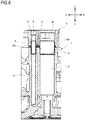
FIG. 6 is a sectional view taken along line D-D inFIG. 3 ; -
FIG. 7A is a plan view of a seal member, andFIG. 7B is a sectional view taken along line E-E ofFIG. 7A ; and -
FIG. 8 is a sectional view illustrating a knock pin formed integrally with the cam holder. - Hereinafter, a cylinder head of an internal combustion engine according to an embodiment of the invention will be described with reference to
FIGS. 1 to 8 . - First, a motorcycle including a cylinder head of an internal combustion engine according to an embodiment of the invention will be described with reference to
FIGS. 1 and2 .FIG. 1 is a left side view of the motorcycle including the cylinder head of the internal combustion engine according to an embodiment of the invention, andFIG. 2 is an enlarged sectional view illustrating the periphery of the internal combustion engine by breaking a part of the motorcycle illustrated inFIG. 1 . The drawings are viewed in orientations of symbols, and inFIGS. 1 and2 , the front and rear, the left and right, and the top and bottom are described according to the direction viewed from an operator, and a front part of a vehicle is Fr, a rear part is Rr, an upper part is U, and a lower part is D in the drawing. - In
FIG. 1 , a motorcycle 41 includes avehicle body frame 42 and acowl cover 43 mounted on thevehicle body frame 42. Thebody frame 42 includes ahead pipe 45 which steerably supports afront fork 44; one pair of left and right main frames 46 and 46 which extends rearward and downward from thehead pipe 45; and one pair of left and right pivot frames 47 and 47 which extends downward from rear ends of the main frames 46 and 46; and one pair of left and right seat rails 48 and 48 which extends rearward and upward from the rear ends of the main frames 46 and 46. Thefront fork 44 supports a front wheel WF so as to freely rotate around an axle 49. A front end of aswing arm 51 is linked to the pivot frames 47 and 47 to be capable of vertically swinging. At the rear end of theswing arm 51, a rear wheel WR is rotatably supported around anaxle 52. Afuel tank 53 is mounted on the main frame 46 from above. Afront riding seat 54a and arear riding seat 54b are supported on theseat rail 48 at the rear part of thefuel tank 53 in order. - An engine
main body 55a of theinternal combustion engine 55 is supported on thevehicle body frame 42 below thefuel tank 53. Theinternal combustion engine 55 is linked to the main frame 46 and the pivot frame 47. Theinternal combustion engine 55 exerts power for generating a rotational force of the rear wheel WR. Fuel is supplied from thefuel tank 53 to theinternal combustion engine 55. - The
cowl cover 43 includes afront cowl 57 which is supported by thevehicle body frame 42 above the front wheel WF, and covers thehead pipe 45 from the front; alower cowl 58 which is supported by thevehicle body frame 42 between the front wheel WF and the rear wheel WR, and covers the enginemain body 55a from below; and a center cowl 59 which connects thefront cowl 57 and thelower cowl 58 to each other continuously from thefront cowl 57 and thelower cowl 58, and partially covers the side of the enginemain body 55a. Thefuel tank 53 is covered with atank cover 61. On thetank cover 61, one pair of left and right side covers 62 which covers a lower portion on the rear side of thefuel tank 53 from both of the left and right sides is continuous between thefuel tank 53 and thefront riding seat 54a. Theseat rail 48 is covered with therear cowl 63 below therear riding seat 54b. - A steering handle 64 is coupled to the
front fork 44. The steering handle 64 is provided with abar handle 65 which extends leftward and rightward from thehead pipe 45 in a direction parallel to the axle 49. Aleft handle grip 66 and aclutch lever 67 are provided at a left end of thebar handle 65. At a right end of thebar handle 65, a grip unit including a right handle grip (not illustrated) and a brake lever are provided. - In
FIG. 2 , the enginemain body 55a includes acylinder block 68 having four cylinders (refer toFIG. 3 ); acylinder head 2 which is coupled to thecylinder block 68 to partition anintake port 69 that communicates with a combustion chamber for each cylinder; and a head cover 73 which is provided with avalve mechanism 72 for opening and closing theintake port 69 with respect to the combustion chamber between thecylinder heads 2. Here, a cylinder axial line H is inclined forward, and theintake port 69 is formed in thecylinder head 2 so as to extend obliquely upward and rearward. - An
intake system 74 is connected to thecylinder head 2. Theintake system 74 includes: anair cleaner 75 which is covered with afuel tank 53 and is disposed above the head cover 73; an electronic controltype throttle device 76 having an upstream end connected to theair cleaner 75; and aninsulator 77 which couples the downstream end of the electronic controltype throttle device 76 to the head cover 73. Theair cleaner 75 includes acleaner case 81 which houses thecleaner element 78 and defines anon-purification chamber 79a and a purification chamber 79b which are separated from each other by thecleaner element 78. - The electronic control
type throttle device 76 includes athrottle body 82. Thethrottle body 82 partitions anintake passage 82a for each of the cylinders. The upstream end of theintake passage 82a is connected to thecleaner case 81 through anair funnel 83 which enters the purification chamber 79b. The downstream end of theintake passage 82a is connected to theintake port 69 of thecylinder head 2. InFIG. 2 , areference numeral 84 denotes a throttle valve, and areference numeral 86 denotes a fuel injection valve. - As illustrated in
FIGS. 3 and4 , theinternal combustion engine 55 is an in-line four-cylinder water-cooled four-stroke internal combustion engine in which four cylinders are disposed in series. Thecylinder head 2 of theinternal combustion engine 55 has a structure in which thecam holder 4 is fixed to the upper side of the cylinder headmain body 3. In the cylinder headmain body 3, an intake port 19i and an exhaust port 19e are provided, and a main body side pluginsertion hole 3h into which anignition plug 6 is inserted is provided between the intake port 19i and the exhaust port 19e. Thecam holder 4 is fixed to the cylinder headmain body 3 with afastening bolt 30 and forms an intake cam bearing portion 20i and an exhaustcam bearing portion 20e which rotatably support an intake camshaft 21i and anexhaust camshaft 21e which are disposed so as to sandwich the main body side pluginsertion hole 3h together with the cylindermain body 3. - In the
cam holder 4, a holder side pluginsertion hole 4h into which theignition plug 6 is inserted is formed in communication with the main body side pluginsertion hole 3h. - As described above, the
internal combustion engine 55 of the embodiment is a four-cylinderinternal combustion engine 55, and the cylinder headmain body 3 includes a plurality of main body side pluginsertion holes 3h into which the ignition plugs 6 that corresponds to each of the cylinders are inserted. Therefore, in thecam holder 4, a plurality of holder sideplug insertion holes 4h which communicates with each of the main body side pluginsertion hole 3h are formed, and in the embodiment, as illustrated inFIG. 5A , thecam holder 4 is integrated between the adjacent cylinders. - As illustrated in
FIG. 4 , one pair offastening bolts 30 for fixing thecam holder 4 to the cylinder headmain body 3 are provided to sandwich the intake camshaft 21i for each of the cylinders, and are provided to sandwich theexhaust camshaft 21e. Therefore, the thickness of the intake cam bearing portion 20i and the exhaustcam bearing portion 20e which rotatably support the intake camshaft 21i and theexhaust camshaft 21e, and the bolt hole through which thefastening bolt 30 is inserted is extremely thin. - Here, a
knock pin 8 for restricting the assembly position of thecam holder 4 and the cylinder headmain body 3 is provided in each of the main body side pluginsertion hole 3h and the holder side pluginsertion hole 4h. In other words, in the main body side pluginsertion hole 3h and the holder side pluginsertion hole 4h into which theignition plug 6 is inserted, theknock pin 8 for restricting the assembly position of thecam holder 4 and the cylinder headmain body 3 is provided across both of theinsertion holes knock pin 8 is a tubular member having substantially the same inner diameter as the diameter of the inner wall surface of the main body side pluginsertion hole 3h and the holder side pluginsertion hole 4h, and is provided in a state of being fitted into the inner wall surface of both of theinsertion holes - As illustrated in
FIG. 5B , theknock pin 8 extends from the cylinderhead side end 4d of the holder side pluginsertion hole 4h and is provided integrally with thecam holder 4. - The
knock pin 8 which is provided integrally with thecam holder 4 may be formed separately from thecam holder 4 and may be integrated with thecam holder 4 by being press-fitted into the holder side pluginsertion hole 4h of thecam holder 4, and as illustrated inFIG. 8 , theknock pin 8 may be formed integrally with thecam holder 4. As theknock pin 8 is formed integrally with thecam holder 4, assembly of theknock pin 8 is unnecessary, and it is possible to reduce the number of components. - As illustrated in
FIGS. 5A to 6 , a main bodyside air passage 15a is provided between adjacent main body side pluginsertion holes 3h in the cylinder headmain body 3, and a holderside air passage 15b which communicates with the main bodyside air passage 15a is provided in thecam holder 4. The main bodyside air passage 15a and the holderside air passage 15b form asecondary air passage 15. - The
secondary air passage 15 is an air passage in which an air outlet is disposed in the vicinity of the exhaust port 19e, the outside air is suctioned into the vicinity of the exhaust port 19e due to the pulsation of the exhaust, and accordingly, the incomplete combustion gas of the exhaust gas is purified. - In the
cylinder head 2 of theinternal combustion engine 55, in addition to the knock pins 8 provided across the main body side pluginsertion hole 3h and the holder side pluginsertion hole 4h, aknock pin 9 for restricting the assembly position of thecam holder 4 and the cylinder headmain body 3 is disposed across the main bodyside air passage 15a and the holderside air passage 15b. - At the outer circumference of the
knock pin 8, as illustrated inFIG. 6 , aseal member 18a having a rectangular section which seals a gap between the cylinder headmain body 3 and thecam holder 4 is disposed. In addition, at the outer circumference of theknock pin 9, aseal member 18b having a rectangular section which seals a gap between the cylinder headmain body 3 and thecam holder 4 is disposed. - Here, in the embodiment, as illustrated in
FIGS. 7A and 7B , theseal member 18a and theseal member 18b are formed as oneseal member 18 being integrated with each other via aconnection portion 18c. - In the embodiment, since the
knock pin 8 for restricting the assembly position of thecam holder 4 and the cylinder headmain body 3 is disposed across the main body side pluginsertion hole 3h into which theignition plug 6 is inserted and the holder side pluginsertion hole 4h, even in a case where there is no space for providing theknock pin 8 on the periphery of thefastening bolt 30 for assembling thecam holder 4 and the cylinder headmain body 3, it is possible to prevent the positional shift by restricting the position at the time of assembling thecam holder 4 and the cylinder headmain body 3 to each other. - Further, according to the embodiment, as the
knock pin 8 is a cylindrical member integrally provided with thecam holder 4 so as to extend from the cylinder headside end portion 4d of the holder side pluginsertion hole 4h, it is possible to omit attaching or detaching work of theknock pin 8 at the time of assembling or detaching thecam holder 4 to and from the cylinder headmain body 3, and to improve workability of assembling and detaching thecam holder 4 and the cylinder headmain body 3 to and from each other. - Further, according to the embodiment, since the
knock pin 8 formed separately is press-fitted into the holder side pluginsertion hole 4h of thecam holder 4 and is integrated with thecam holder 4, even when the shape of thecam holder 4 is made different, by preparing general-purpose knock pins 8, theknock pin 8 can also be employed in other models. - Further, according to the embodiment, since the
internal combustion engine 55 is multi-cylinder, at least onecam holder 4 is integrated between the adjacent cylinders, and the knock pins 8 are provided in each of the main body side pluginsertion holes 3h and the holder sideplug insertion holes 4h in theintegrated cam holder 4, it is possible to prevent the positional shift of theentire cam holder 4 with the plurality ofknock pins 8 disposed side by side at the center of thecam holder 4. In addition, by integrating thecam holder 4, it is possible to reduce the number ofcam holders 4. - Further, according to the embodiment, the cylinder head
main body 3 includes the main bodyside air passage 15a between the adjacent main body side pluginsertion holes 3h, in thecam holder 4, the holder side air passage15b which communicates with the main bodyside air passage 15a is formed, theknock pin 9 for restricting the assembly position of thecam holder 4 and the cylinder headmain body 3 is disposed across the main bodyside air passage 15a and the holderside air passage 15b, and accordingly, it is possible to improve positional shift prevention performance. - Further, according to the embodiment, since the
seal member 18a having a rectangular section which seals the gap between the cylinder headmain body 3 and thecam holder 4 is disposed at the outer circumference of theknock pin 8, theseal member 18a is compressed and deformed when thecam holder 4 is assembled and tightly adheres to the outer circumferential surface of theknock pin 8, and accordingly, it is possible to ensure sealing performance. - Further, according to the embodiment, since the
seal member 18b provided at the outer circumference of theknock pin 9 provided on thesecondary air passage 15 side and theseal member 18a provided at the outer circumference of theknock pin 8 provided on the plug insertion hole side are integrally formed, in addition to the reduction in number of components of the seal member, it is possible to mount the seal member simultaneously at two locations at the time of assembly work, and to improve workability. - Although the embodiment of the invention has been described above, the invention is not limited thereto, but can be appropriately modified. For example, in the above-described embodiment, the structure in which the
cam holder 4 is integrated between the two cylinders is illustrated, but a structure in which three or more cylinders are integrated may be employed. In addition, although theseal member 18a is integrally formed with theseal member 18b provided at the outer circumference of theother knock pin 9, the invention is not limited thereto, and may not be integrated. In addition, in the above-described embodiment, the structure in which the knock pins 8 and 9 are integrally provided on thecam holder 4 is described, but may be integrally provided on the cylinder headmain body 3.
Claims (8)
- A cylinder head (2) of an internal combustion engine (55) comprising:a cylinder head main body (3) which is formed with a main body side plug insertion hole (3h) into which an ignition plug (6) is inserted;a cam holder (4) which is fixed to the cylinder head main body (3) and forms cam bearing portions (20i, 20e) together with the cylinder head main body (3), wherein the cam bearing portions (20i, 20e) are configured to rotatably support an intake camshaft (21i) and an exhaust camshaft (21e), respectively, which are disposed to sandwich the main body side plug insertion hole (3h), and wherein the cam holder (4) is formed with a holder side plug insertion hole (4h) which communicates with the main body side plug insertion hole (3h) and into which the ignition plug (6) is inserted; anda knock pin (8) which is disposed across the main body side plug insertion hole (3h) and the holder side plug insertion hole (4h) to restrict assembly positions of the cam holder (4) and the cylinder head main body (3).
- The cylinder head (2) according to claim 1,
wherein the knock pin (8) is a tubular member which is provided integrally with the cam holder (4) to extend from a cylinder head side end portion (4d) of the holder side plug insertion hole (4h). - The cylinder head (2) according to claim 2,
wherein the knock pin (8) is formed integrally with the cam holder (4). - The cylinder head (2) according to claim 2,
wherein the knock pin (8) is formed as a separate member from the cam holder (4) and is integrated with the cam holder (4) by being press-fitted into the holder side plug insertion hole (4h) of the cam holder (4). - The cylinder head (2) according to any one of claims 1 to 4,
wherein the internal combustion engine (55) is a multi-cylinder engine,
wherein the cylinder head main body (3) is formed with a plurality of main body side plug insertion holes (3h), into which ignition plugs (6) corresponding to respective cylinders are inserted,
wherein the cam holder (4) is formed with a plurality of holder side plug insertion holes (4h) which respectively communicate with the main body side plug insertion holes (3h) of the cylinder head main body (3) and into which the ignition plugs (6) are inserted, respectively,
wherein the cam holder (4) is integrated for at least one pair of adjacent cylinders, and
wherein the knock pin (8) is provided across the main body side plug insertion hole (3h) and the holder side plug insertion hole (4h) in the integrated cam holder (4). - The cylinder head (2) according to claim 5,
wherein the cylinder head main body (3) is formed with a main body side air passage (15a) between adjacent main body side plug insertion holes (3h), and
wherein the cam holder (4) is formed with a holder side air passage (15b) which communicates with the main body side air passage (15a),
the cylinder head further comprising:another knock pin (9) which is disposed across the main body side air passage (15a) and the holder side air passage (15b) to restrict the assembly positions of the cam holder (4) and the cylinder head main body (3). - The cylinder head (2) according to any one of claims 1 to 6, further comprising:a seal member (18a) which has a rectangular section and is disposed at an outer circumference of the knock pin (8) to seal a gap between the cylinder head main body (3) and the cam holder (4).
- The cylinder head (2) according to claim 7,
wherein the cylinder head main body (3) is formed with a main body side air passage (15a) between adjacent main body side plug insertion holes (3h),
wherein the cam holder (4) is formed with a holder side air passage (15b) which communicates with the main body side air passage (15a),
the cylinder head further comprising:another knock pin (9) which is disposed across the main body side air passage (15a) and the holder side air passage (15b) to restrict the assembly positions of the cam holder (4) and the cylinder head main body (3),wherein the seal member (18a) is integrally formed with a seal member (18b) which is disposed at an outer circumference of the other knock pin (9) to seal a gap between the cam holder (4) and the cylinder head main body (3).
Applications Claiming Priority (1)
| Application Number | Priority Date | Filing Date | Title |
|---|---|---|---|
| JP2017056332A JP6865078B2 (en) | 2017-03-22 | 2017-03-22 | Internal combustion engine cylinder head |
Publications (2)
| Publication Number | Publication Date |
|---|---|
| EP3379064A1 true EP3379064A1 (en) | 2018-09-26 |
| EP3379064B1 EP3379064B1 (en) | 2020-06-10 |
Family
ID=61599018
Family Applications (1)
| Application Number | Title | Priority Date | Filing Date |
|---|---|---|---|
| EP18160636.9A Active EP3379064B1 (en) | 2017-03-22 | 2018-03-08 | Cylinder head of internal combustion engine |
Country Status (3)
| Country | Link |
|---|---|
| US (1) | US10900441B2 (en) |
| EP (1) | EP3379064B1 (en) |
| JP (1) | JP6865078B2 (en) |
Cited By (2)
| Publication number | Priority date | Publication date | Assignee | Title |
|---|---|---|---|---|
| CN109356741A (en) * | 2018-11-27 | 2019-02-19 | 义乌吉利发动机有限公司 | A kind of cylinder head of automobile engine |
| CN109404155A (en) * | 2018-11-06 | 2019-03-01 | 广西玉柴机器股份有限公司 | A kind of cylinder cover for diesel engine structure |
Citations (11)
| Publication number | Priority date | Publication date | Assignee | Title |
|---|---|---|---|---|
| EP0434638A1 (en) * | 1989-12-22 | 1991-06-26 | FIAT AUTO S.p.A. | An internal combustion engine with controlled ignition and twin overhead camshafts for motor vehicles |
| AT1683U2 (en) * | 1997-04-03 | 1997-09-25 | Avl List Gmbh | INTERNAL COMBUSTION ENGINE WITH SEVERAL VALVES PER CYLINDER |
| DE19808718A1 (en) * | 1998-03-02 | 1999-09-09 | Audi Ag | Lubricator device for cylinder head of especially multi-cylinder IC engine |
| JP2000087705A (en) | 1998-09-14 | 2000-03-28 | Honda Motor Co Ltd | 4-cycle engine |
| JP3417424B2 (en) * | 1994-03-03 | 2003-06-16 | いすゞ自動車株式会社 | Cylinder head of DOHC internal combustion engine |
| JP2004293469A (en) * | 2003-03-27 | 2004-10-21 | Suzuki Motor Corp | Cylinder head structure of engine |
| WO2008029247A1 (en) * | 2006-09-04 | 2008-03-13 | Toyota Jidosha Kabushiki Kaisha | Cam cap and oil passage connection structure |
| DE202008005019U1 (en) * | 2008-04-10 | 2009-08-20 | Mann+Hummel Gmbh | Cylinder head cover for a cylinder head of an internal combustion engine |
| JP2011208546A (en) * | 2010-03-29 | 2011-10-20 | Honda Motor Co Ltd | Valve gear of internal combustion engine |
| JP2011241700A (en) | 2010-05-14 | 2011-12-01 | Otics Corp | Bearing structure of camshaft |
| EP2444600A1 (en) * | 2009-06-18 | 2012-04-25 | JTEKT Corporation | Camshaft device, engine with same, and method for manufacturing camshaft device |
Family Cites Families (3)
| Publication number | Priority date | Publication date | Assignee | Title |
|---|---|---|---|---|
| JPS5793616A (en) * | 1980-12-03 | 1982-06-10 | Honda Motor Co Ltd | Exhaust purifier for internal combustion engine |
| JPS6318165A (en) | 1986-07-09 | 1988-01-26 | Honda Motor Co Ltd | Engine |
| JP2007291979A (en) | 2006-04-26 | 2007-11-08 | Honda Motor Co Ltd | Ignition plug mounting structure of internal combustion engine |
-
2017
- 2017-03-22 JP JP2017056332A patent/JP6865078B2/en active Active
-
2018
- 2018-03-07 US US15/914,023 patent/US10900441B2/en active Active
- 2018-03-08 EP EP18160636.9A patent/EP3379064B1/en active Active
Patent Citations (11)
| Publication number | Priority date | Publication date | Assignee | Title |
|---|---|---|---|---|
| EP0434638A1 (en) * | 1989-12-22 | 1991-06-26 | FIAT AUTO S.p.A. | An internal combustion engine with controlled ignition and twin overhead camshafts for motor vehicles |
| JP3417424B2 (en) * | 1994-03-03 | 2003-06-16 | いすゞ自動車株式会社 | Cylinder head of DOHC internal combustion engine |
| AT1683U2 (en) * | 1997-04-03 | 1997-09-25 | Avl List Gmbh | INTERNAL COMBUSTION ENGINE WITH SEVERAL VALVES PER CYLINDER |
| DE19808718A1 (en) * | 1998-03-02 | 1999-09-09 | Audi Ag | Lubricator device for cylinder head of especially multi-cylinder IC engine |
| JP2000087705A (en) | 1998-09-14 | 2000-03-28 | Honda Motor Co Ltd | 4-cycle engine |
| JP2004293469A (en) * | 2003-03-27 | 2004-10-21 | Suzuki Motor Corp | Cylinder head structure of engine |
| WO2008029247A1 (en) * | 2006-09-04 | 2008-03-13 | Toyota Jidosha Kabushiki Kaisha | Cam cap and oil passage connection structure |
| DE202008005019U1 (en) * | 2008-04-10 | 2009-08-20 | Mann+Hummel Gmbh | Cylinder head cover for a cylinder head of an internal combustion engine |
| EP2444600A1 (en) * | 2009-06-18 | 2012-04-25 | JTEKT Corporation | Camshaft device, engine with same, and method for manufacturing camshaft device |
| JP2011208546A (en) * | 2010-03-29 | 2011-10-20 | Honda Motor Co Ltd | Valve gear of internal combustion engine |
| JP2011241700A (en) | 2010-05-14 | 2011-12-01 | Otics Corp | Bearing structure of camshaft |
Cited By (2)
| Publication number | Priority date | Publication date | Assignee | Title |
|---|---|---|---|---|
| CN109404155A (en) * | 2018-11-06 | 2019-03-01 | 广西玉柴机器股份有限公司 | A kind of cylinder cover for diesel engine structure |
| CN109356741A (en) * | 2018-11-27 | 2019-02-19 | 义乌吉利发动机有限公司 | A kind of cylinder head of automobile engine |
Also Published As
| Publication number | Publication date |
|---|---|
| JP6865078B2 (en) | 2021-04-28 |
| JP2018159304A (en) | 2018-10-11 |
| US10900441B2 (en) | 2021-01-26 |
| EP3379064B1 (en) | 2020-06-10 |
| US20180274476A1 (en) | 2018-09-27 |
Similar Documents
| Publication | Publication Date | Title |
|---|---|---|
| US10526982B2 (en) | Internal combustion engine with supercharger for saddle-ride type vehicle | |
| US8047180B2 (en) | Intake air control system of V-type internal combustion engine | |
| US8113168B2 (en) | Engine unit and vehicle including the same | |
| CA2895733C (en) | Motorcycle | |
| JP4167635B2 (en) | Fuel supply device for V-type engine for vehicle | |
| US10385804B2 (en) | Single cylinder internal combustion engine | |
| EP3379064B1 (en) | Cylinder head of internal combustion engine | |
| US10151238B2 (en) | Internal combustion engine for saddle-ride type vehicle | |
| JP6444351B2 (en) | Oil filter mounting structure for in-vehicle internal combustion engine | |
| US8042521B2 (en) | Engine unit and vehicle provided with the same | |
| JP4645387B2 (en) | Secondary air supply device for motorcycles | |
| US11053898B2 (en) | Saddle riding vehicle | |
| JP4695047B2 (en) | Engine fuel supply system | |
| JP2011256835A (en) | Cylinder head structure of internal combustion engine | |
| US20150007786A1 (en) | Fuel supply apparatus of internal combustion engine | |
| US10273905B2 (en) | Exhaust emission control device for internal combustion engine | |
| US11773756B2 (en) | Variable valve timing system | |
| JP2009092021A (en) | Engine unit and vehicle equipped therewith | |
| JP6714648B2 (en) | Internal combustion engine for saddle type vehicles | |
| JP6897212B2 (en) | Engine exhaust purification device and vehicle | |
| JP6233250B2 (en) | Fuel piping structure of fuel supply device for internal combustion engine | |
| US20180274394A1 (en) | Dohc-type internal combustion engine | |
| JP5757762B2 (en) | Engine throttle control device | |
| EP3521606A1 (en) | Intake component attachment structure for vehicular internal combustion engine | |
| JP2008082195A (en) | Throttle body mounting structure |
Legal Events
| Date | Code | Title | Description |
|---|---|---|---|
| PUAI | Public reference made under article 153(3) epc to a published international application that has entered the european phase |
Free format text: ORIGINAL CODE: 0009012 |
|
| STAA | Information on the status of an ep patent application or granted ep patent |
Free format text: STATUS: REQUEST FOR EXAMINATION WAS MADE |
|
| 17P | Request for examination filed |
Effective date: 20180308 |
|
| AK | Designated contracting states |
Kind code of ref document: A1 Designated state(s): AL AT BE BG CH CY CZ DE DK EE ES FI FR GB GR HR HU IE IS IT LI LT LU LV MC MK MT NL NO PL PT RO RS SE SI SK SM TR |
|
| AX | Request for extension of the european patent |
Extension state: BA ME |
|
| RIC1 | Information provided on ipc code assigned before grant |
Ipc: F01L 1/46 20060101ALI20191125BHEP Ipc: F01L 1/047 20060101ALI20191125BHEP Ipc: F02F 1/24 20060101AFI20191125BHEP |
|
| GRAP | Despatch of communication of intention to grant a patent |
Free format text: ORIGINAL CODE: EPIDOSNIGR1 |
|
| STAA | Information on the status of an ep patent application or granted ep patent |
Free format text: STATUS: GRANT OF PATENT IS INTENDED |
|
| INTG | Intention to grant announced |
Effective date: 20200108 |
|
| GRAS | Grant fee paid |
Free format text: ORIGINAL CODE: EPIDOSNIGR3 |
|
| GRAA | (expected) grant |
Free format text: ORIGINAL CODE: 0009210 |
|
| STAA | Information on the status of an ep patent application or granted ep patent |
Free format text: STATUS: THE PATENT HAS BEEN GRANTED |
|
| AK | Designated contracting states |
Kind code of ref document: B1 Designated state(s): AL AT BE BG CH CY CZ DE DK EE ES FI FR GB GR HR HU IE IS IT LI LT LU LV MC MK MT NL NO PL PT RO RS SE SI SK SM TR |
|
| REG | Reference to a national code |
Ref country code: GB Ref legal event code: FG4D |
|
| REG | Reference to a national code |
Ref country code: CH Ref legal event code: EP Ref country code: AT Ref legal event code: REF Ref document number: 1279383 Country of ref document: AT Kind code of ref document: T Effective date: 20200615 |
|
| REG | Reference to a national code |
Ref country code: DE Ref legal event code: R096 Ref document number: 602018005122 Country of ref document: DE |
|
| REG | Reference to a national code |
Ref country code: IE Ref legal event code: FG4D |
|
| REG | Reference to a national code |
Ref country code: LT Ref legal event code: MG4D |
|
| PG25 | Lapsed in a contracting state [announced via postgrant information from national office to epo] |
Ref country code: LT Free format text: LAPSE BECAUSE OF FAILURE TO SUBMIT A TRANSLATION OF THE DESCRIPTION OR TO PAY THE FEE WITHIN THE PRESCRIBED TIME-LIMIT Effective date: 20200610 Ref country code: FI Free format text: LAPSE BECAUSE OF FAILURE TO SUBMIT A TRANSLATION OF THE DESCRIPTION OR TO PAY THE FEE WITHIN THE PRESCRIBED TIME-LIMIT Effective date: 20200610 Ref country code: NO Free format text: LAPSE BECAUSE OF FAILURE TO SUBMIT A TRANSLATION OF THE DESCRIPTION OR TO PAY THE FEE WITHIN THE PRESCRIBED TIME-LIMIT Effective date: 20200910 Ref country code: SE Free format text: LAPSE BECAUSE OF FAILURE TO SUBMIT A TRANSLATION OF THE DESCRIPTION OR TO PAY THE FEE WITHIN THE PRESCRIBED TIME-LIMIT Effective date: 20200610 Ref country code: GR Free format text: LAPSE BECAUSE OF FAILURE TO SUBMIT A TRANSLATION OF THE DESCRIPTION OR TO PAY THE FEE WITHIN THE PRESCRIBED TIME-LIMIT Effective date: 20200911 |
|
| REG | Reference to a national code |
Ref country code: NL Ref legal event code: MP Effective date: 20200610 |
|
| PG25 | Lapsed in a contracting state [announced via postgrant information from national office to epo] |
Ref country code: BG Free format text: LAPSE BECAUSE OF FAILURE TO SUBMIT A TRANSLATION OF THE DESCRIPTION OR TO PAY THE FEE WITHIN THE PRESCRIBED TIME-LIMIT Effective date: 20200910 Ref country code: LV Free format text: LAPSE BECAUSE OF FAILURE TO SUBMIT A TRANSLATION OF THE DESCRIPTION OR TO PAY THE FEE WITHIN THE PRESCRIBED TIME-LIMIT Effective date: 20200610 Ref country code: RS Free format text: LAPSE BECAUSE OF FAILURE TO SUBMIT A TRANSLATION OF THE DESCRIPTION OR TO PAY THE FEE WITHIN THE PRESCRIBED TIME-LIMIT Effective date: 20200610 Ref country code: HR Free format text: LAPSE BECAUSE OF FAILURE TO SUBMIT A TRANSLATION OF THE DESCRIPTION OR TO PAY THE FEE WITHIN THE PRESCRIBED TIME-LIMIT Effective date: 20200610 |
|
| REG | Reference to a national code |
Ref country code: AT Ref legal event code: MK05 Ref document number: 1279383 Country of ref document: AT Kind code of ref document: T Effective date: 20200610 |
|
| PG25 | Lapsed in a contracting state [announced via postgrant information from national office to epo] |
Ref country code: AL Free format text: LAPSE BECAUSE OF FAILURE TO SUBMIT A TRANSLATION OF THE DESCRIPTION OR TO PAY THE FEE WITHIN THE PRESCRIBED TIME-LIMIT Effective date: 20200610 Ref country code: NL Free format text: LAPSE BECAUSE OF FAILURE TO SUBMIT A TRANSLATION OF THE DESCRIPTION OR TO PAY THE FEE WITHIN THE PRESCRIBED TIME-LIMIT Effective date: 20200610 |
|
| PG25 | Lapsed in a contracting state [announced via postgrant information from national office to epo] |
Ref country code: EE Free format text: LAPSE BECAUSE OF FAILURE TO SUBMIT A TRANSLATION OF THE DESCRIPTION OR TO PAY THE FEE WITHIN THE PRESCRIBED TIME-LIMIT Effective date: 20200610 Ref country code: AT Free format text: LAPSE BECAUSE OF FAILURE TO SUBMIT A TRANSLATION OF THE DESCRIPTION OR TO PAY THE FEE WITHIN THE PRESCRIBED TIME-LIMIT Effective date: 20200610 Ref country code: SM Free format text: LAPSE BECAUSE OF FAILURE TO SUBMIT A TRANSLATION OF THE DESCRIPTION OR TO PAY THE FEE WITHIN THE PRESCRIBED TIME-LIMIT Effective date: 20200610 Ref country code: ES Free format text: LAPSE BECAUSE OF FAILURE TO SUBMIT A TRANSLATION OF THE DESCRIPTION OR TO PAY THE FEE WITHIN THE PRESCRIBED TIME-LIMIT Effective date: 20200610 Ref country code: RO Free format text: LAPSE BECAUSE OF FAILURE TO SUBMIT A TRANSLATION OF THE DESCRIPTION OR TO PAY THE FEE WITHIN THE PRESCRIBED TIME-LIMIT Effective date: 20200610 Ref country code: CZ Free format text: LAPSE BECAUSE OF FAILURE TO SUBMIT A TRANSLATION OF THE DESCRIPTION OR TO PAY THE FEE WITHIN THE PRESCRIBED TIME-LIMIT Effective date: 20200610 Ref country code: IT Free format text: LAPSE BECAUSE OF FAILURE TO SUBMIT A TRANSLATION OF THE DESCRIPTION OR TO PAY THE FEE WITHIN THE PRESCRIBED TIME-LIMIT Effective date: 20200610 Ref country code: PT Free format text: LAPSE BECAUSE OF FAILURE TO SUBMIT A TRANSLATION OF THE DESCRIPTION OR TO PAY THE FEE WITHIN THE PRESCRIBED TIME-LIMIT Effective date: 20201012 |
|
| PG25 | Lapsed in a contracting state [announced via postgrant information from national office to epo] |
Ref country code: PL Free format text: LAPSE BECAUSE OF FAILURE TO SUBMIT A TRANSLATION OF THE DESCRIPTION OR TO PAY THE FEE WITHIN THE PRESCRIBED TIME-LIMIT Effective date: 20200610 Ref country code: SK Free format text: LAPSE BECAUSE OF FAILURE TO SUBMIT A TRANSLATION OF THE DESCRIPTION OR TO PAY THE FEE WITHIN THE PRESCRIBED TIME-LIMIT Effective date: 20200610 Ref country code: IS Free format text: LAPSE BECAUSE OF FAILURE TO SUBMIT A TRANSLATION OF THE DESCRIPTION OR TO PAY THE FEE WITHIN THE PRESCRIBED TIME-LIMIT Effective date: 20201010 |
|
| REG | Reference to a national code |
Ref country code: DE Ref legal event code: R097 Ref document number: 602018005122 Country of ref document: DE |
|
| PLBE | No opposition filed within time limit |
Free format text: ORIGINAL CODE: 0009261 |
|
| STAA | Information on the status of an ep patent application or granted ep patent |
Free format text: STATUS: NO OPPOSITION FILED WITHIN TIME LIMIT |
|
| PG25 | Lapsed in a contracting state [announced via postgrant information from national office to epo] |
Ref country code: DK Free format text: LAPSE BECAUSE OF FAILURE TO SUBMIT A TRANSLATION OF THE DESCRIPTION OR TO PAY THE FEE WITHIN THE PRESCRIBED TIME-LIMIT Effective date: 20200610 |
|
| 26N | No opposition filed |
Effective date: 20210311 |
|
| PG25 | Lapsed in a contracting state [announced via postgrant information from national office to epo] |
Ref country code: SI Free format text: LAPSE BECAUSE OF FAILURE TO SUBMIT A TRANSLATION OF THE DESCRIPTION OR TO PAY THE FEE WITHIN THE PRESCRIBED TIME-LIMIT Effective date: 20200610 |
|
| REG | Reference to a national code |
Ref country code: DE Ref legal event code: R084 Ref document number: 602018005122 Country of ref document: DE |
|
| PG25 | Lapsed in a contracting state [announced via postgrant information from national office to epo] |
Ref country code: MC Free format text: LAPSE BECAUSE OF FAILURE TO SUBMIT A TRANSLATION OF THE DESCRIPTION OR TO PAY THE FEE WITHIN THE PRESCRIBED TIME-LIMIT Effective date: 20200610 |
|
| REG | Reference to a national code |
Ref country code: CH Ref legal event code: PL |
|
| REG | Reference to a national code |
Ref country code: BE Ref legal event code: MM Effective date: 20210331 |
|
| PG25 | Lapsed in a contracting state [announced via postgrant information from national office to epo] |
Ref country code: LU Free format text: LAPSE BECAUSE OF NON-PAYMENT OF DUE FEES Effective date: 20210308 Ref country code: LI Free format text: LAPSE BECAUSE OF NON-PAYMENT OF DUE FEES Effective date: 20210331 Ref country code: CH Free format text: LAPSE BECAUSE OF NON-PAYMENT OF DUE FEES Effective date: 20210331 Ref country code: FR Free format text: LAPSE BECAUSE OF NON-PAYMENT OF DUE FEES Effective date: 20210331 Ref country code: IE Free format text: LAPSE BECAUSE OF NON-PAYMENT OF DUE FEES Effective date: 20210308 |
|
| PG25 | Lapsed in a contracting state [announced via postgrant information from national office to epo] |
Ref country code: BE Free format text: LAPSE BECAUSE OF NON-PAYMENT OF DUE FEES Effective date: 20210331 |
|
| GBPC | Gb: european patent ceased through non-payment of renewal fee |
Effective date: 20220308 |
|
| PG25 | Lapsed in a contracting state [announced via postgrant information from national office to epo] |
Ref country code: GB Free format text: LAPSE BECAUSE OF NON-PAYMENT OF DUE FEES Effective date: 20220308 |
|
| PGFP | Annual fee paid to national office [announced via postgrant information from national office to epo] |
Ref country code: DE Payment date: 20230110 Year of fee payment: 6 |
|
| PG25 | Lapsed in a contracting state [announced via postgrant information from national office to epo] |
Ref country code: CY Free format text: LAPSE BECAUSE OF FAILURE TO SUBMIT A TRANSLATION OF THE DESCRIPTION OR TO PAY THE FEE WITHIN THE PRESCRIBED TIME-LIMIT Effective date: 20200610 |
|
| PG25 | Lapsed in a contracting state [announced via postgrant information from national office to epo] |
Ref country code: HU Free format text: LAPSE BECAUSE OF FAILURE TO SUBMIT A TRANSLATION OF THE DESCRIPTION OR TO PAY THE FEE WITHIN THE PRESCRIBED TIME-LIMIT; INVALID AB INITIO Effective date: 20180308 |