EP3379048B1 - Motorsystem - Google Patents
Motorsystem Download PDFInfo
- Publication number
- EP3379048B1 EP3379048B1 EP18162986.6A EP18162986A EP3379048B1 EP 3379048 B1 EP3379048 B1 EP 3379048B1 EP 18162986 A EP18162986 A EP 18162986A EP 3379048 B1 EP3379048 B1 EP 3379048B1
- Authority
- EP
- European Patent Office
- Prior art keywords
- turbine
- engine
- exhaust line
- combustion
- exhaust
- Prior art date
- Legal status (The legal status is an assumption and is not a legal conclusion. Google has not performed a legal analysis and makes no representation as to the accuracy of the status listed.)
- Active
Links
Images


Classifications
-
- F—MECHANICAL ENGINEERING; LIGHTING; HEATING; WEAPONS; BLASTING
- F02—COMBUSTION ENGINES; HOT-GAS OR COMBUSTION-PRODUCT ENGINE PLANTS
- F02G—HOT GAS OR COMBUSTION-PRODUCT POSITIVE-DISPLACEMENT ENGINE PLANTS; USE OF WASTE HEAT OF COMBUSTION ENGINES; NOT OTHERWISE PROVIDED FOR
- F02G5/00—Profiting from waste heat of combustion engines, not otherwise provided for
- F02G5/02—Profiting from waste heat of exhaust gases
-
- F—MECHANICAL ENGINEERING; LIGHTING; HEATING; WEAPONS; BLASTING
- F01—MACHINES OR ENGINES IN GENERAL; ENGINE PLANTS IN GENERAL; STEAM ENGINES
- F01N—GAS-FLOW SILENCERS OR EXHAUST APPARATUS FOR MACHINES OR ENGINES IN GENERAL; GAS-FLOW SILENCERS OR EXHAUST APPARATUS FOR INTERNAL-COMBUSTION ENGINES
- F01N5/00—Exhaust or silencing apparatus combined or associated with devices profiting by exhaust energy
- F01N5/02—Exhaust or silencing apparatus combined or associated with devices profiting by exhaust energy the devices using heat
-
- F—MECHANICAL ENGINEERING; LIGHTING; HEATING; WEAPONS; BLASTING
- F02—COMBUSTION ENGINES; HOT-GAS OR COMBUSTION-PRODUCT ENGINE PLANTS
- F02B—INTERNAL-COMBUSTION PISTON ENGINES; COMBUSTION ENGINES IN GENERAL
- F02B37/00—Engines characterised by provision of pumps driven at least for part of the time by exhaust
- F02B37/004—Engines characterised by provision of pumps driven at least for part of the time by exhaust with exhaust drives arranged in series
-
- F—MECHANICAL ENGINEERING; LIGHTING; HEATING; WEAPONS; BLASTING
- F02—COMBUSTION ENGINES; HOT-GAS OR COMBUSTION-PRODUCT ENGINE PLANTS
- F02B—INTERNAL-COMBUSTION PISTON ENGINES; COMBUSTION ENGINES IN GENERAL
- F02B39/00—Component parts, details, or accessories relating to, driven charging or scavenging pumps, not provided for in groups F02B33/00 - F02B37/00
- F02B39/02—Drives of pumps; Varying pump drive gear ratio
- F02B39/08—Non-mechanical drives, e.g. fluid drives having variable gear ratio
- F02B39/10—Non-mechanical drives, e.g. fluid drives having variable gear ratio electric
-
- F—MECHANICAL ENGINEERING; LIGHTING; HEATING; WEAPONS; BLASTING
- F02—COMBUSTION ENGINES; HOT-GAS OR COMBUSTION-PRODUCT ENGINE PLANTS
- F02B—INTERNAL-COMBUSTION PISTON ENGINES; COMBUSTION ENGINES IN GENERAL
- F02B41/00—Engines characterised by special means for improving conversion of heat or pressure energy into mechanical power
- F02B41/02—Engines with prolonged expansion
- F02B41/10—Engines with prolonged expansion in exhaust turbines
-
- Y—GENERAL TAGGING OF NEW TECHNOLOGICAL DEVELOPMENTS; GENERAL TAGGING OF CROSS-SECTIONAL TECHNOLOGIES SPANNING OVER SEVERAL SECTIONS OF THE IPC; TECHNICAL SUBJECTS COVERED BY FORMER USPC CROSS-REFERENCE ART COLLECTIONS [XRACs] AND DIGESTS
- Y02—TECHNOLOGIES OR APPLICATIONS FOR MITIGATION OR ADAPTATION AGAINST CLIMATE CHANGE
- Y02T—CLIMATE CHANGE MITIGATION TECHNOLOGIES RELATED TO TRANSPORTATION
- Y02T10/00—Road transport of goods or passengers
- Y02T10/10—Internal combustion engine [ICE] based vehicles
- Y02T10/12—Improving ICE efficiencies
Definitions
- the invention relates to the field of internal combustion engines and it can be applied both to the field of vehicle powering and boat powering and to the field of fixed installation for the production of electrical energy.
- the invention relates to the field of combined cycles.
- WO02053890A1 corresponds to the preamble of claim 1 and discloses a Diesel engine combined with a post-combustor and a turbine, arranged downstream of the post-combustor.
- Diesel cycle engines usually implement an after-treatment system (ATS), which comprises different pollutant reduction devices, such as the DOC for the reduction of CO and HC, the DPF for the reduction of particulate and the SCR for the reduction of NOx.
- ATS after-treatment system
- pollutant reduction devices such as the DOC for the reduction of CO and HC, the DPF for the reduction of particulate and the SCR for the reduction of NOx.
- the reason behind this invention is that of solving the problems deriving from the use of an ATS in a Diesel cycle engine, as already mentioned above.
- a further object of the invention is to keep the efficiency of the Diesel cycle engine intact when the engine is properly integrated in a combined cycle; said combined cycle allows to eliminate the classical ATS for Diesel cycle engines, replacing it with a so-called 3-way catalyst, which is usually used in petrol engines.
- Petrol engines unlike Diesel engines, have a stoichiometric ratio between fuel and air, i.e. the so-called lambda factor is equal to 1.
- Diesel cycle engines instead, work with a lambda factor exceeding 1, which means that they operate with excess oxygen.
- 3-way catalysts are not capable of catalyzing NOx and CO in the presence of excess oxygen, namely with a lambda factor exceeding 1.
- the fuel flow rate has a lambda value equal to 1.0.
- the supercharging pressure of the engine is increased in proportion to the increase in backpressure caused by the introduction of a turbine in the exhaust circuit of the engine and by the aforesaid combustor, so as to exploit the enthalpy increase generated by the combustor; therefore a turbine is inserted downstream of said combustion chamber.
- This turbine causes an increase in the pressure of the exhaust gases upstream of said turbine and, hence, also downstream of the exhaust valves of the internal combustion engine.
- the operating conditions of the Diesel engine are optimized by increasing the supercharging pressure of the engine with suitable compression means arranged in the intake circuit of the internal combustion engine, so that the supercharging pressure is approximately equal to the exhaust backpressure.
- the means for injecting fuel into the combustor and the fresh air compressor arranged in the intake line are designed to operate in a coordinated manner.
- a lambda sensor (UEGO) is installed upstream of the second injection means and/or immediately upstream of the ATS, so as to perform a feedback control of the fuel dosage.
- UEGO lambda sensor
- the combustion device which is operatively connected to the exhaust manifold of the Diesel cycle engine, completes the combustion thereof permitting the implementation of a 3-way catalyst, which requires a lambda factor equal to 1.0, without jeopardizing the efficiency of the Diesel cycle engine.
- a 3-way catalyst not only is cheaper than an ATS for Diesel engine, but it is also more reliable over time, reducing maintenance times and costs.
- the components represented with broken lines are optionals, whereas the broken connection lines are electric and/or data bus lines.
- second component does not imply the presence of a "first” component.
- first component does not imply the presence of a "first” component.
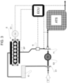
- Figure 1 shows one of the basic variants of the engine system for vehicles or fixed installations according to the invention.
- Diesel cycle internal combustion engine E comprising an intake line IP and an exhaust line EP and first fuel injection means (not indicated).
- second combustion means N for introducing and burning fuel in the exhaust line, so as to obtain a second combustion operatively downstream of the one performed in the Diesel engine, hence exploiting the residual oxygen of the exhaust gases of the first combustion.
- second combustion means N comprise any known device, such as a carburetor or injector, designed to introduce fuel, preferably Diesel fuel, into said combustion chamber arranged on the exhaust line, in order to obtain said second combustion.
- a carburetor or injector designed to introduce fuel, preferably Diesel fuel, into said combustion chamber arranged on the exhaust line, in order to obtain said second combustion.
- a first turbine T1 is arranged on said exhaust line downstream of said second injection means.
- the last element operatively connected to the exhaust line is a pollutant reduction device ATS (After Treatment System). It is designed to treat the exhaust gases produced both by the internal combustion engine E and by the second combustion means N.
- ATS After Treatment System
- a processing unit ECU which preferably coincides with the control unit of the internal combustion engine E, is configured to control an injection/introduction of fuel operated by the second combustion means N, so as to maintain a lambda value equal to 1.0 in the exhaust gases entering said pollutant reduction device ATS.
- at least one lambda or UEGO sensor is associated with the exhaust line.
- said at least one sensor is associated with the exhaust line immediately upstream of the ATS.
- Further sensors can be arranged downstream of the ATS.
- first injection means to introduce fuel into the Diesel engine and second injection means to introduce fuel into the combustion chamber along the exhaust line and that the first injection means are separate and distinct from the second injection means.
- the pressures experienced by the internal combustion engine at the intake and at the exhaust preferably are such that the internal combustion engine produces a PMEP value - acronym standing from pumping mean effective pressure, a term that is well known to a person skilled in the art - close to zero.
- the supercharging pressure can be slightly smaller than the backpressure experienced at the exhaust, when there are exhaust gas recirculation means (EGR), which are described below.
- EGR exhaust gas recirculation means
- the compression ratio defined for the compressor primarily is a function of the air/fuel ratio defined for the internal combustion engine E, and the following parameters play a role:
- the pressure ratio after and before the turbine (P_before_turbine/P_after_turbine) is approximately equal to the pressure ratio after and before the compressor (P_before_compressor/P_after_compressor).
- the internal combustion engine E can drive the transmission of a terrestrial or boat vehicle or can cause the rotation of a first electro generator G1.
- Figures 1 - 9 show that the intake line IP houses at least one cooler IC for the compressed air introduced into the internal combustion engine E.
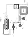
- Figure 4 shows a second turbine T2 arranged on said exhaust line downstream of the first turbine T1.
- the second turbine T2 is arranged upstream of the second combustion means N.
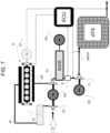
- the system comprises means to perform a waste heat recovery (WHR) cycle comprising a first heat exchanger associated with said exhaust line so as to extract heat from said exhaust gases.
- WHR waste heat recovery
- the steam turbine of the WHR can also be connected to a vehicle transmission or to a fourth electric generator so as to generate electrical energy.
- the WHR is arranged immediately downstream of the second turbine T2. It is evident that the diagram of figure 7 was built on the basis of the diagram of figure 6 , but the presence of the compressor is optional in case the second turbine is connected to the generator G3.
- the diagram can comprise exhaust gas recirculation means (EGR). They can be high-pressure or low-pressure exhaust gas recirculation means.
- a point of the exhaust line immediately upstream or immediately downstream of the ATS is connected to a point upstream of said one or more compressors arranged on the intake line.
- said exhaust gas drawing point is not located between the second combustion means N and said first turbine.
- An EGR valve is controlled by the processing unit ECU so as to manage the quantity of recirculated fluid.
- the drawing point on the exhaust line preferably is obtained in a point immediately downstream of the first heat exchanger of the WHR, so as to lower the temperature of the gases to be recirculated, thus creating a high-pressure or low-pressure EGR according to the diagrams of figure 7 .
- the ATS is of the type requiring the lambda to be 1.0, exactly like petrol engines. Therefore, even though the internal combustion engine is a Diesel cycle engine, the ATS is of the type used in petrol engines, a so-called 3-way catalyst, which has a very small cost.
- the fuel injected along the exhaust line is not necessarily Diesel fuel, it can be any kind of fuel.
- the high temperature reached upstream of the first turbine T1 determines a significant boost.
- the volume efficiency In order to limit the peak pressure of the cylinder, which would lead to significant mechanical stresses, the volume efficiency must be reduced according to what described in relation to the implementation of the Miller/Atkinson timing.
- a PMEP slightly above or under the zero value is a target of the optimal sizing of the system, so as to enable a high-pressure EGR or so as to maximize the efficiency of the engine.
- the supplying maps of the internal combustion engine must preferably be such as to keep the lambda value as low as possible, so as to maintain the temperature of the exhaust gases within a temperature interval that is compatible with the turbine/s arranged on the exhaust line.
- gas turbines usually operate with excess oxygen, i.e. with lambda >>1.
- the internal combustion engine operates as a combustor, whereas the turbine, besides completing the combustion, operates as a turbocharger for the internal combustion engine; therefore, in this variant, see for example figures 2 and 3 , there is complete interdependency between the two combustion stages.
- the transmission shafts of the different turbines can be operatively associated, for example through gear transmission organs, so as to operate, together, on a vehicle transmission or on a generator defining a turbo-compound diagram, alternatively to a relative compressor or to a dedicated electric generator.
- any one of the compressors rather than being caused to rotate by the shaft of a turbine, can be driven by an electric motor.
- the ECU controls the Diesel cycle engine, the generators/electric motors G1 - G4, monitors the other things, the quantity of oxygen in the exhaust gases downstream of the Diesel engine and/or immediately upstream of the ATS, and controls the introduction of fuel of the second combustion means N into the combustion chamber.
Landscapes
- Engineering & Computer Science (AREA)
- Chemical & Material Sciences (AREA)
- Combustion & Propulsion (AREA)
- Mechanical Engineering (AREA)
- General Engineering & Computer Science (AREA)
- Supercharger (AREA)
Claims (14)
- Kraftmaschinensystem für Fahrzeuge und feste Installationen auf der Grundlage des Dieselkreisprozesses, das Folgendes umfasst:- eine Dieselkreisprozess-Brennkraftmaschine (E), die eine Einlassleitung (IP) und eine Abgasleitung (EP) und jeweilige erste Kraftstoffeinspritzmittel umfasst,- eine Brennkammer, die an der Abgasleitung der Dieselkreisprozess-Kraftmaschine angeordnet ist, um den Restsauerstoff zu verbrennen, der in den Abgasen enthalten ist, die durch die Dieselkreisprozess-Kraftmaschine erzeugt werden,- eine erste Turbine (T1), die der Abgasleitung (EP) funktionstechnisch zugeordnet ist,- zweite Verbrennungsmittel (N), die eine Einspritzeinrichtung zum Einleiten und Verbrennen von Kraftstoff in der Brennkammer umfassen und stromabwärts der Brennkraftmaschine und unmittelbar stromaufwärts der ersten Turbine (T1) angeordnet sind,- eine Schadstoffverringerungsvorrichtung (ATS), die mit der Abgasleitung stromabwärts der ersten Turbine (T1) verbunden ist, um die Abgase zu behandeln, die durch die Dieselkreisprozess-Kraftmaschine und durch die zweiten Verbrennungsmittel (N) erzeugt werden,- Verarbeitungsmittel (ECU), die konfiguriert sind, mindestens eine Verbrennung der zweiten Verbrennungsmittel (N) zu steuern;dadurch gekennzeichnet, dass die Verarbeitungsmittel (ECU) konfiguriert sind, die Einleitung von Kraftstoff, die durch die zweiten Verbrennungsmittel (N) betrieben wird, zu steuern, um einen Lambdawert der Abgase, die in die Schadstoffverringerungsvorrichtung (ATS) eintreten, auf 1,0 zu halten; wobei die Schadstoffverringerungsvorrichtung (ATS) ein Dreiwegekatalysator ist.
- System nach Anspruch 1, das ferner einen Lambda- oder UEGO-Sensor umfasst, der unmittelbar stromaufwärts der Schadstoffverringerungsvorrichtung (ATS) installiert ist, um eine Rückkopplungssteuerung der Kraftstoffdosierung durchzuführen.
- System nach Anspruch 1 oder 2, wobei zwischen der Dieselkraftmaschine und der Brennkammer keine Frischluft eingeleitet wird.
- System nach Anspruch 1, wobei die erste Turbine hilft, einen Gegendruck in der Abgasleitung (EP) zu definieren, ein erster Kompressor (C1, C2), der durch die erste Turbine oder durch einen fest zugeordneten Elektromotor angetrieben wird und eine oder mehrere Komprimierungsstufen definiert, an der Einlassleitung (IP) angeordnet ist und der erste Kompressor geeignet ist, einen Druck in der Einlassleitung bereitzustellen, der ungefähr gleich dem Gegendruck ist.
- System nach Anspruch 4, wobei der Kompressor und die zweiten Verbrennungsmittel (N) zum Einleiten und Verbrennen von Kraftstoff in der Abgasleitung derart angeordnet sind, dass sie in einer koordinierten Weise zusammenzuwirken.
- System nach einem der Ansprüche 1 oder 5, wobei die erste Turbine ausgelegt ist, einen Elektromotorgenerator drehend zu führen.
- System nach einem der Ansprüche 1 bis 6, wobei die Dieselkreisprozess-Kraftmaschine mindestens einen Zylinder und einen jeweiligen Kolben und ein jeweiliges Einlassventil umfasst und das Einlassventil gesteuert wird, während eines Komprimierungszyklus geschlossen zu werden, bevor oder nachdem der Kolben einen jeweiligen unteren Totpunkt verlassen hat, um einen Miller- oder einen Atkinson-Kreisprozess zu erreichen.
- System nach einem der vorhergehenden Ansprüche, das ferner eine weitere Turbine (T2) umfasst, die in der Abgasleitung stromabwärts der ersten Turbine angeordnet ist.
- System nach einem der Ansprüche 1 bis 7, das ferner eine weitere Turbine (T2) umfasst, die in der Abgasleitung stromaufwärts der zweiten Verbrennungsmittel (N) angeordnet ist.
- System nach Anspruch 8 oder 9, wobei die weitere Turbine (T2) einen jeweiligen zweiten Kompressor (C3, C3'), der in der Einlassleitung angeordnet ist, drehend antreibt.
- System nach Anspruch 8 oder 9, wobei die weitere Turbine einen jeweiligen elektrischen Generator drehend antreibt.
- System nach einem der vorhergehenden Ansprüche, das ferner Mittel zum Erhalten eines Wärmerückgewinnungszyklus (WHR) umfasst, die einen Wärmetauscher umfassen, der der Abgasleitung zugeordnet ist, um Wärme aus den Abgasen zu extrahieren, wobei der Wärmetauscher stromaufwärts der zweiten Verbrennungsmittel (N) angeordnet ist.
- System nach einem der Ansprüche 1 bis 11, das ferner Mittel zum Erhalten eines Wärmerückgewinnungszyklus (WHR) umfasst, die einen Wärmetauscher umfassen, der der Abgasleitung zugeordnet ist, um Wärme aus den Abgasen zu extrahieren, wobei der Wärmetauscher stromabwärts der ersten Turbine (T1) angeordnet ist.
- System nach einem der vorhergehenden Ansprüche, das ferner Abgasrückführungsmittel (AGR) für hohen Druck (HAGR) oder niedrigen Druck (LAGR) oder interne AGR (IAGR) umfasst, wobei die Rückführungsmittel als eine Funktion eines gewünschten (niedrigeren) Liefergrads der Brennkraftmaschine gesteuert werden.
Applications Claiming Priority (1)
| Application Number | Priority Date | Filing Date | Title |
|---|---|---|---|
| IT102017000030576A IT201700030576A1 (it) | 2017-03-20 | 2017-03-20 | Sistema motore per veicoli ed installazioni fisse basato su ciclo diesel |
Publications (2)
| Publication Number | Publication Date |
|---|---|
| EP3379048A1 EP3379048A1 (de) | 2018-09-26 |
| EP3379048B1 true EP3379048B1 (de) | 2025-06-25 |
Family
ID=59521517
Family Applications (1)
| Application Number | Title | Priority Date | Filing Date |
|---|---|---|---|
| EP18162986.6A Active EP3379048B1 (de) | 2017-03-20 | 2018-03-20 | Motorsystem |
Country Status (2)
| Country | Link |
|---|---|
| EP (1) | EP3379048B1 (de) |
| IT (1) | IT201700030576A1 (de) |
Family Cites Families (4)
| Publication number | Priority date | Publication date | Assignee | Title |
|---|---|---|---|---|
| JPH01152019U (de) * | 1988-04-11 | 1989-10-19 | ||
| WO2002053890A1 (en) * | 2000-12-27 | 2002-07-11 | Yanmar Co., Ltd. | Internal combustion engine with exhaust emission control device |
| US7950231B2 (en) * | 2007-10-26 | 2011-05-31 | Deere & Company | Low emission turbo compound engine system |
| EP2328772A1 (de) * | 2008-09-23 | 2011-06-08 | Aerovironment inc. | Kraftwerk sowie steuersystem und -verfahren dafür |
-
2017
- 2017-03-20 IT IT102017000030576A patent/IT201700030576A1/it unknown
-
2018
- 2018-03-20 EP EP18162986.6A patent/EP3379048B1/de active Active
Also Published As
| Publication number | Publication date |
|---|---|
| EP3379048A1 (de) | 2018-09-26 |
| IT201700030576A1 (it) | 2018-09-20 |
Similar Documents
| Publication | Publication Date | Title |
|---|---|---|
| EP2053208B1 (de) | Turboverbundmaschinensystem mit niedriger Emission | |
| CN101922338B (zh) | 一种运转内燃发动机及测量其排气温度的方法 | |
| EP2378096B1 (de) | Motor | |
| CN102216593B (zh) | 用于降低车辆内燃机的排气中的NOx含量的方法和设备 | |
| JP5722444B2 (ja) | 内燃機関の排気ラインに還元体を噴射するための設備 | |
| JP2010513766A (ja) | Scr反応器を備える大型ターボ過給型ディーゼルエンジン | |
| CN103775174A (zh) | 内燃机 | |
| US20100263372A1 (en) | Two-stage supercharging system with exhaust gas purification device for internal-combustion engine and method for controlling same | |
| CN109209618B (zh) | 具有改进的后处理激活的车辆涡轮增压器系统 | |
| CN111561400B (zh) | 控制机动车辆的火花点火式内燃机的排放物的系统和方法 | |
| US10900430B2 (en) | Internal combustion engine and control device for internal combustion engine | |
| EP3379048B1 (de) | Motorsystem | |
| US20140157758A1 (en) | After-Treatment System and Method for Six-Stroke Combustion Cycle | |
| GB2505224A (en) | Internal combustion engine with direct water injection during the exhaust stroke | |
| US6481206B1 (en) | Compound cycle internal combustion engine | |
| US20200284187A1 (en) | Twin Scroll Turbocharger with Waste Heat Recovery | |
| EP2642102B1 (de) | Steuerungsvorrichtung für einen verbrennungsmotor | |
| EP3379067B1 (de) | Motorsystem | |
| GB2423797A (en) | An internal combustion engine having a turbocompounder | |
| US12546275B2 (en) | Combustion engine arrangement and method | |
| US12467415B2 (en) | Air handling systems and controls for internal combustion engines operating with a miller cycle | |
| ES2657082B2 (es) | Equipo de recuperacion de energia de gases procedentes de la combustion | |
| US20170167448A1 (en) | Engine system | |
| WO2025114835A1 (en) | Heating control strategy of an exhaust gas aftertreatment system | |
| EP4731885A1 (de) | Verfahren zum betrieb eines mehrzylinder-viertakt-kolbenmotors und viertakt-brennkraftkolbenmotor |
Legal Events
| Date | Code | Title | Description |
|---|---|---|---|
| PUAI | Public reference made under article 153(3) epc to a published international application that has entered the european phase |
Free format text: ORIGINAL CODE: 0009012 |
|
| STAA | Information on the status of an ep patent application or granted ep patent |
Free format text: STATUS: THE APPLICATION HAS BEEN PUBLISHED |
|
| AK | Designated contracting states |
Kind code of ref document: A1 Designated state(s): AL AT BE BG CH CY CZ DE DK EE ES FI FR GB GR HR HU IE IS IT LI LT LU LV MC MK MT NL NO PL PT RO RS SE SI SK SM TR |
|
| AX | Request for extension of the european patent |
Extension state: BA ME |
|
| STAA | Information on the status of an ep patent application or granted ep patent |
Free format text: STATUS: REQUEST FOR EXAMINATION WAS MADE |
|
| STAA | Information on the status of an ep patent application or granted ep patent |
Free format text: STATUS: EXAMINATION IS IN PROGRESS |
|
| 17P | Request for examination filed |
Effective date: 20190325 |
|
| RBV | Designated contracting states (corrected) |
Designated state(s): AL AT BE BG CH CY CZ DE DK EE ES FI FR GB GR HR HU IE IS IT LI LT LU LV MC MK MT NL NO PL PT RO RS SE SI SK SM TR |
|
| 17Q | First examination report despatched |
Effective date: 20190417 |
|
| GRAP | Despatch of communication of intention to grant a patent |
Free format text: ORIGINAL CODE: EPIDOSNIGR1 |
|
| STAA | Information on the status of an ep patent application or granted ep patent |
Free format text: STATUS: GRANT OF PATENT IS INTENDED |
|
| INTG | Intention to grant announced |
Effective date: 20250121 |
|
| GRAS | Grant fee paid |
Free format text: ORIGINAL CODE: EPIDOSNIGR3 |
|
| GRAA | (expected) grant |
Free format text: ORIGINAL CODE: 0009210 |
|
| STAA | Information on the status of an ep patent application or granted ep patent |
Free format text: STATUS: THE PATENT HAS BEEN GRANTED |
|
| P01 | Opt-out of the competence of the unified patent court (upc) registered |
Free format text: CASE NUMBER: APP_21748/2025 Effective date: 20250507 |
|
| AK | Designated contracting states |
Kind code of ref document: B1 Designated state(s): AL AT BE BG CH CY CZ DE DK EE ES FI FR GB GR HR HU IE IS IT LI LT LU LV MC MK MT NL NO PL PT RO RS SE SI SK SM TR |
|
| REG | Reference to a national code |
Ref country code: GB Ref legal event code: FG4D |
|
| REG | Reference to a national code |
Ref country code: CH Ref legal event code: EP |
|
| REG | Reference to a national code |
Ref country code: CH Ref legal event code: EP |
|
| REG | Reference to a national code |
Ref country code: IE Ref legal event code: FG4D |
|
| REG | Reference to a national code |
Ref country code: DE Ref legal event code: R096 Ref document number: 602018082844 Country of ref document: DE |
|
| PG25 | Lapsed in a contracting state [announced via postgrant information from national office to epo] |
Ref country code: FI Free format text: LAPSE BECAUSE OF FAILURE TO SUBMIT A TRANSLATION OF THE DESCRIPTION OR TO PAY THE FEE WITHIN THE PRESCRIBED TIME-LIMIT Effective date: 20250625 |
|
| REG | Reference to a national code |
Ref country code: LT Ref legal event code: MG9D |
|
| PG25 | Lapsed in a contracting state [announced via postgrant information from national office to epo] |
Ref country code: GR Free format text: LAPSE BECAUSE OF FAILURE TO SUBMIT A TRANSLATION OF THE DESCRIPTION OR TO PAY THE FEE WITHIN THE PRESCRIBED TIME-LIMIT Effective date: 20250926 Ref country code: NO Free format text: LAPSE BECAUSE OF FAILURE TO SUBMIT A TRANSLATION OF THE DESCRIPTION OR TO PAY THE FEE WITHIN THE PRESCRIBED TIME-LIMIT Effective date: 20250925 |
|
| PG25 | Lapsed in a contracting state [announced via postgrant information from national office to epo] |
Ref country code: BG Free format text: LAPSE BECAUSE OF FAILURE TO SUBMIT A TRANSLATION OF THE DESCRIPTION OR TO PAY THE FEE WITHIN THE PRESCRIBED TIME-LIMIT Effective date: 20250625 |
|
| PG25 | Lapsed in a contracting state [announced via postgrant information from national office to epo] |
Ref country code: HR Free format text: LAPSE BECAUSE OF FAILURE TO SUBMIT A TRANSLATION OF THE DESCRIPTION OR TO PAY THE FEE WITHIN THE PRESCRIBED TIME-LIMIT Effective date: 20250625 |
|
| PG25 | Lapsed in a contracting state [announced via postgrant information from national office to epo] |
Ref country code: RS Free format text: LAPSE BECAUSE OF FAILURE TO SUBMIT A TRANSLATION OF THE DESCRIPTION OR TO PAY THE FEE WITHIN THE PRESCRIBED TIME-LIMIT Effective date: 20250925 |
|
| PG25 | Lapsed in a contracting state [announced via postgrant information from national office to epo] |
Ref country code: LV Free format text: LAPSE BECAUSE OF FAILURE TO SUBMIT A TRANSLATION OF THE DESCRIPTION OR TO PAY THE FEE WITHIN THE PRESCRIBED TIME-LIMIT Effective date: 20250625 |
|
| REG | Reference to a national code |
Ref country code: NL Ref legal event code: MP Effective date: 20250625 |
|
| PG25 | Lapsed in a contracting state [announced via postgrant information from national office to epo] |
Ref country code: NL Free format text: LAPSE BECAUSE OF FAILURE TO SUBMIT A TRANSLATION OF THE DESCRIPTION OR TO PAY THE FEE WITHIN THE PRESCRIBED TIME-LIMIT Effective date: 20250625 |
|
| PG25 | Lapsed in a contracting state [announced via postgrant information from national office to epo] |
Ref country code: PT Free format text: LAPSE BECAUSE OF FAILURE TO SUBMIT A TRANSLATION OF THE DESCRIPTION OR TO PAY THE FEE WITHIN THE PRESCRIBED TIME-LIMIT Effective date: 20251027 |
|
| REG | Reference to a national code |
Ref country code: AT Ref legal event code: MK05 Ref document number: 1806640 Country of ref document: AT Kind code of ref document: T Effective date: 20250625 |
|
| PG25 | Lapsed in a contracting state [announced via postgrant information from national office to epo] |
Ref country code: IS Free format text: LAPSE BECAUSE OF FAILURE TO SUBMIT A TRANSLATION OF THE DESCRIPTION OR TO PAY THE FEE WITHIN THE PRESCRIBED TIME-LIMIT Effective date: 20251025 |
|
| PG25 | Lapsed in a contracting state [announced via postgrant information from national office to epo] |
Ref country code: AT Free format text: LAPSE BECAUSE OF FAILURE TO SUBMIT A TRANSLATION OF THE DESCRIPTION OR TO PAY THE FEE WITHIN THE PRESCRIBED TIME-LIMIT Effective date: 20250625 Ref country code: SM Free format text: LAPSE BECAUSE OF FAILURE TO SUBMIT A TRANSLATION OF THE DESCRIPTION OR TO PAY THE FEE WITHIN THE PRESCRIBED TIME-LIMIT Effective date: 20250625 |
|
| PG25 | Lapsed in a contracting state [announced via postgrant information from national office to epo] |
Ref country code: CZ Free format text: LAPSE BECAUSE OF FAILURE TO SUBMIT A TRANSLATION OF THE DESCRIPTION OR TO PAY THE FEE WITHIN THE PRESCRIBED TIME-LIMIT Effective date: 20250625 |
|
| PG25 | Lapsed in a contracting state [announced via postgrant information from national office to epo] |
Ref country code: PL Free format text: LAPSE BECAUSE OF FAILURE TO SUBMIT A TRANSLATION OF THE DESCRIPTION OR TO PAY THE FEE WITHIN THE PRESCRIBED TIME-LIMIT Effective date: 20250625 |
|
| PG25 | Lapsed in a contracting state [announced via postgrant information from national office to epo] |
Ref country code: EE Free format text: LAPSE BECAUSE OF FAILURE TO SUBMIT A TRANSLATION OF THE DESCRIPTION OR TO PAY THE FEE WITHIN THE PRESCRIBED TIME-LIMIT Effective date: 20250625 |
|
| PG25 | Lapsed in a contracting state [announced via postgrant information from national office to epo] |
Ref country code: SK Free format text: LAPSE BECAUSE OF FAILURE TO SUBMIT A TRANSLATION OF THE DESCRIPTION OR TO PAY THE FEE WITHIN THE PRESCRIBED TIME-LIMIT Effective date: 20250625 |
|
| PG25 | Lapsed in a contracting state [announced via postgrant information from national office to epo] |
Ref country code: ES Free format text: LAPSE BECAUSE OF FAILURE TO SUBMIT A TRANSLATION OF THE DESCRIPTION OR TO PAY THE FEE WITHIN THE PRESCRIBED TIME-LIMIT Effective date: 20250625 |
|
| PG25 | Lapsed in a contracting state [announced via postgrant information from national office to epo] |
Ref country code: DK Free format text: LAPSE BECAUSE OF FAILURE TO SUBMIT A TRANSLATION OF THE DESCRIPTION OR TO PAY THE FEE WITHIN THE PRESCRIBED TIME-LIMIT Effective date: 20250625 |
|
| PGFP | Annual fee paid to national office [announced via postgrant information from national office to epo] |
Ref country code: DE Payment date: 20260320 Year of fee payment: 9 |
|
| PGFP | Annual fee paid to national office [announced via postgrant information from national office to epo] |
Ref country code: IT Payment date: 20260311 Year of fee payment: 9 |
|
| PGFP | Annual fee paid to national office [announced via postgrant information from national office to epo] |
Ref country code: FR Payment date: 20260323 Year of fee payment: 9 |