EP3379002A1 - Flexible hanging type module building structure - Google Patents
Flexible hanging type module building structure Download PDFInfo
- Publication number
- EP3379002A1 EP3379002A1 EP17833220.1A EP17833220A EP3379002A1 EP 3379002 A1 EP3379002 A1 EP 3379002A1 EP 17833220 A EP17833220 A EP 17833220A EP 3379002 A1 EP3379002 A1 EP 3379002A1
- Authority
- EP
- European Patent Office
- Prior art keywords
- module
- modules
- core tube
- tube structure
- rod member
- Prior art date
- Legal status (The legal status is an assumption and is not a legal conclusion. Google has not performed a legal analysis and makes no representation as to the accuracy of the status listed.)
- Granted
Links
Images



Classifications
-
- E—FIXED CONSTRUCTIONS
- E04—BUILDING
- E04B—GENERAL BUILDING CONSTRUCTIONS; WALLS, e.g. PARTITIONS; ROOFS; FLOORS; CEILINGS; INSULATION OR OTHER PROTECTION OF BUILDINGS
- E04B1/00—Constructions in general; Structures which are not restricted either to walls, e.g. partitions, or floors or ceilings or roofs
- E04B1/34—Extraordinary structures, e.g. with suspended or cantilever parts supported by masts or tower-like structures enclosing elevators or stairs; Features relating to the elastic stability
- E04B1/3404—Extraordinary structures, e.g. with suspended or cantilever parts supported by masts or tower-like structures enclosing elevators or stairs; Features relating to the elastic stability supported by masts or tower-like structures
-
- E—FIXED CONSTRUCTIONS
- E04—BUILDING
- E04B—GENERAL BUILDING CONSTRUCTIONS; WALLS, e.g. PARTITIONS; ROOFS; FLOORS; CEILINGS; INSULATION OR OTHER PROTECTION OF BUILDINGS
- E04B1/00—Constructions in general; Structures which are not restricted either to walls, e.g. partitions, or floors or ceilings or roofs
- E04B1/34—Extraordinary structures, e.g. with suspended or cantilever parts supported by masts or tower-like structures enclosing elevators or stairs; Features relating to the elastic stability
-
- E—FIXED CONSTRUCTIONS
- E04—BUILDING
- E04B—GENERAL BUILDING CONSTRUCTIONS; WALLS, e.g. PARTITIONS; ROOFS; FLOORS; CEILINGS; INSULATION OR OTHER PROTECTION OF BUILDINGS
- E04B1/00—Constructions in general; Structures which are not restricted either to walls, e.g. partitions, or floors or ceilings or roofs
- E04B1/38—Connections for building structures in general
-
- E—FIXED CONSTRUCTIONS
- E04—BUILDING
- E04B—GENERAL BUILDING CONSTRUCTIONS; WALLS, e.g. PARTITIONS; ROOFS; FLOORS; CEILINGS; INSULATION OR OTHER PROTECTION OF BUILDINGS
- E04B1/00—Constructions in general; Structures which are not restricted either to walls, e.g. partitions, or floors or ceilings or roofs
- E04B1/62—Insulation or other protection; Elements or use of specified material therefor
- E04B1/92—Protection against other undesired influences or dangers
- E04B1/98—Protection against other undesired influences or dangers against vibrations or shocks; against mechanical destruction, e.g. by air-raids
-
- E—FIXED CONSTRUCTIONS
- E04—BUILDING
- E04H—BUILDINGS OR LIKE STRUCTURES FOR PARTICULAR PURPOSES; SWIMMING OR SPLASH BATHS OR POOLS; MASTS; FENCING; TENTS OR CANOPIES, IN GENERAL
- E04H9/00—Buildings, groups of buildings or shelters adapted to withstand or provide protection against abnormal external influences, e.g. war-like action, earthquake or extreme climate
- E04H9/02—Buildings, groups of buildings or shelters adapted to withstand or provide protection against abnormal external influences, e.g. war-like action, earthquake or extreme climate withstanding earthquake or sinking of ground
-
- E—FIXED CONSTRUCTIONS
- E04—BUILDING
- E04H—BUILDINGS OR LIKE STRUCTURES FOR PARTICULAR PURPOSES; SWIMMING OR SPLASH BATHS OR POOLS; MASTS; FENCING; TENTS OR CANOPIES, IN GENERAL
- E04H9/00—Buildings, groups of buildings or shelters adapted to withstand or provide protection against abnormal external influences, e.g. war-like action, earthquake or extreme climate
- E04H9/02—Buildings, groups of buildings or shelters adapted to withstand or provide protection against abnormal external influences, e.g. war-like action, earthquake or extreme climate withstanding earthquake or sinking of ground
- E04H9/025—Structures with concrete columns
Definitions
- the present invention belongs to the field of civil engineering technologies, and more particularly, to flexibly suspended modular building structure.
- a module building is a prefabricated assembly-type three-dimensional box unit, one unit generally has 1 to 3 rooms, the module unit is usually manufactured by steel structure, the module manufacturing and equipment installation account for 90% of the total construction quantity, and are both finished on the assembly line of the factory, which has high mechanization and industrialization degrees, and reduces the pollutant discharge.
- the manufacturer integrates the external wall, decoration, furniture, equipment, etc. in the box unit (module) and delivers them to the site for lifting and assembling, which not only has convenient construction in structure part, but also omits the decoration and other work in a later stage.
- the module building has the advantages on the following aspect mainly: due to high integration, the subsequent decoration, equipment and pipeline installation and other procedures are omitted, which further shortens the construction time and saves the human resources on site; each module forms a structure system itself; no matter the transportation and lifting, or the positioning does not need additional supporting or bracing parts, and relatively convenient piling in place can be used; moreover, the decoration and equipment installation conducted by the factory assembly-line further improve the indoor quality, which better complies with the market requirements on commercial houses.
- the module building is applied to but is not limited to the following occasions: a project with an urgent construction period, such as school dormitories where the new student needs to move in on schedule; a project that is short of manpower, such as the construction with scale in remote regions; a project under challenging weather conditions, such as winter construction; and a project having special requirements on the decoration quality, such as starred hotel, etc.
- a project with an urgent construction period such as school dormitories where the new student needs to move in on schedule
- a project that is short of manpower such as the construction with scale in remote regions
- a project under challenging weather conditions such as winter construction
- a project having special requirements on the decoration quality such as starred hotel, etc.
- the members in the module have limited size, which cannot reach a very high level of horizontal bearing capacity. Therefore, in the practical engineering application at current, multi-story and high-rise module buildings need to be externally added with an anti-lateral structure which can be a concrete core tube or other forms to help the module buildings to bear lateral loads.
- the module delivers the horizontal load to the core tube through effective connection, and the module itself only bears the vertical load and little horizontal load. Therefore, in the high-rise module building case, the structure form of module + concrete core tube is generally used, an anti-horizontal seismic force system only has one defense line (the core tube), which is a relatively unreasonable structure form. overlarge horizontal load delivering from the module to the core tube usually causes great material consumption.
- the self-weight of the module is directly delivered downwardly, the module at the bottom bears overlarge vertical load, which increases the size of the internal members of the module, and further increases the self-weight of the structure, so as to affect the use function.
- the present invention in order to overcome the defects in the prior art, provides a flexibly suspended modular building structure.
- a flexibly suspended modular building structure comprises a vertically arranged concrete core tube structure, wherein a transfer story is arranged at the upper end of the core tube structure, the transfer story is formed by a steel truss, effectively connected to the concrete core tube, and cantilevered outside the core tube structure, multiple modules with certain spaces reserved therebetween are hung below the transfer story, the modules adjacent in the vertical direction are connected through a set of hanging rod members, the upper end of each hanging rod member is movably connected to a ceiling beam located in the upper module, the lower end of each hanging rod member is pin- connected to a ceiling beam located in the lower module, the hanging rod member arranged on the uppermost module is pin- connected to the transfer story, and dampers are arranged between all the modules and the core tube structure at their floor levels.
- the flexible connection refers to "hinging", “flexible connection” and “the connection in hanging rod members without bending moment”.
- a limiting buffer device is arranged between the modules adjacent in the vertical direction, and the limiting buffer device is used for avoiding the modules adjacent in the vertical direction from vertical colliding when the horizontal relative displacement is relatively large.
- the limiting buffer device comprises two connected rod members, the free end of each rod member is respectively connected to the modules adjacent in the vertical direction, wherein one rod member is connected to a base angle located at the upper module, and the other rod member is connected to a top angle located at the lower module and adjacent to the upper module in the vertical direction, a steel wire rope is connected between the two rod members, and when the position between the rod members is in an initial state, the steel wire rope is in a relaxed state.
- the ceiling beam of each module is provided with an extended section outside a beam column node, the end portion of the hanging rod member is connected to a universal joint, the universal joint is connected to a web of a T-shaped connecting steel plate, and a flange of the T-shaped connecting steel plate is welded to the extended section of the ceiling beam of the module.
- a slideable prefabricated floorslab is arranged between each module and the core tube structure, one end of the prefabricated floorslab is connected to the beam column node at the floor of the module, and the other end of the prefabricated floorslab is placed on a floorslab of the core tube structure.
- Channel steel is pre-buried in the prefabricated floorslab, the channel steel is connected to a connecting steel plate bolt, the connecting steel plate is welded with the beam column node at the floor of the module, the other end of the prefabricated floorslab is placed on a groove of the floor of the core tube structure, and the two sides of a contact surface for placing are provided with a pre-buried contact steel plate; the vertical end face of the groove is provided with a pre-buried anti-collision steel plate, and the contact steel plate and the anti-collision steel plate are welded on a pre-buried anchor bar of the prefabricated floorslab.
- a module inter-story damper is arranged between two modules adjacent in the vertical direction, the two ends of the module inter-story damper are respectively connected to the beam column node of the floor of the upper module and the beam column node of the ceiling of the lower module.
- the object of setting the inter-story damper is that in case of a rare earthquake, when other dampers are damaged because of exceeding the stroke and then are retreated from working, the module inter-story damper is still in the operating stroke due to little relative movement, which continuously provides a necessary energy dissipation way for the structure.
- a module group consisting of multiple modules piled up from bottom to top is arranged on a ground base set with a core tube structure, the multiple modules piled up are mutually connected, the modules located at the ground base are connected to the ground base, and the modules piled up are no more than four stories.
- the flexible hanging type module building structure according to the present invention has the following beneficial effects.
- 1 refers to core tube structure
- 2 refers to transfer story
- 3 refers to module
- 4 refers to hanging rod member
- 5 refers to damper
- 6 refers to diagonal supporting member
- 7 refers to limiting buffer device
- 8 refers to rod member
- 9 refers to steel wire rope
- 10 refers to ceiling beam
- 11 refers to module column
- 12 refers to stiffening rib
- 13 refers to universal joint
- 14 refers to T-shaped connecting steel plate
- 15 refers to prefabricated floorslab
- 16 refers to module inter-story damper
- 17 refers to core tube floorslab
- 18 refers to high-strength bolt
- 19 refers to connecting steel plate
- 20 refers to pre- buried channel steel
- 21 refers to pre-buried contact steel plate
- 22 refers to pre-buried anti-collision steel plate
- 23 refers to pre-buried anchor bar
- 24 refers to module group
- 25 refers to lifting platform
- 26 refers to pre-buried connecting member
- a flexibly suspended modular building structure as shown in Fig. 1 to Fig. 3 comprises a vertically arranged concrete core tube structure 1, wherein the core tube structure 1 is a key system to bear all horizontal loads and vertical loads of the whole structure, a transfer story 2 is arranged at the upper end of the core tube structure 1, multiple modules 3 with certain spaces reserved therebetween are hung below the transfer story 2, the modules 3 adjacent in the vertical direction are connected through a set of hanging rod members 4, the upper end of each hanging rod member 4 is pin- connected to a ceiling beam 5 located in the upper module 3, the lower end of each hanging rod member is pin- connected to a ceiling beam 5 located in the lower module 3, and the ceiling beam 5 is the beam located at the top surface of the module 3; and the hanging rod member 4 arranged on the uppermost modules 3 is pin- connected to the transfer story 2, dampers 5 are arranged between floors of all the modules 3 and the core tube structure, all the dampers 5 play a role of energy dissipation when the modules 3 and the core tube structure 1 move relatively, and the dampers 5
- a limiting buffer device 7 is arranged between the modules 3 adjacent in the vertical direction, and the limiting buffer device 7 is used for avoiding the modules 3 adjacent in the vertical direction from vertical colliding when the horizontal relative displacement is relatively large.
- the limiting buffer device 7 comprises two mutually connected rod members 8, the free end of each rod member 8 is respectively connected to the modules 3 adjacent in the vertical direction, wherein one rod member 8 is connected to a base angle located at the upper module 3, and the other rod member 8 is connected to a top angle located at the lower module 3 and adjacent to the upper module 3 in the vertical direction.
- a steel wire rope 9 is arranged between the two rod members 8, when the position between the rod members 8 is in an initial state, the steel wire rope 9 is in a relaxed state, the two rod members 8 and the steel wire rope 9 in a relaxed initial state form an "A-shaped" device, this A-shaped rod member group plays a role of leverage, which aims at reducing the elongation of the steel wire rope by scale to avoid the steel wire rope from being ruptured too early.
- the floor of each module 3 is connected to the core tube structure 1 through the damper 5, the damper 5 plays a main role of energy dissipation when the modules 3 and the core tube structure 1 move relatively, and the damper 5 has certain elastic stiffness to provide horizontal stiffness for the structure of the modules 3.
- the ceiling beam 10 of the module is provided with an extended section outside a beam column node, the ceiling beam is provided with a stiffening rib 12 at a corresponding position, the hanging rod member 4 is a hollow circular steel tube generally, the end portion of the hanging rod member is connected to a universal joint 13, the universal joint 13 is connected to a web of a T-shaped connecting steel plate 14 through a bolt, a flange of the T-shaped connecting steel plate 14 is welded to the extended section of the ceiling beam 10 of the module, and the welding is conducted according to the requirement on rigid connection.
- the extended section of the ceiling beam of the module plays a role of allowing the hanging rod member 4 to swing in a certain range without collision.
- Each module 3 is internally provided with a diagonal supporting member 6, and the diagonal supporting member 6 strengthens the structure of the module from the interior.
- a slideable prefabricated floorslab 15 is arranged between each module 3 and the core tube structure 1, so as to keep the access of personnel while the module and the core tube structure move relatively.
- Channel steel 20 is pre-buried in the prefabricated floorslab 15, the Channel steel 20 before being pre-buried is connected to a connecting steel plate 19 through a high-strength bolt 18, the connecting steel plate 19 is welded to the beam column node at the floor of the module on site, the other end of the prefabricated floorslab 15 is placed on a groove of a core tube floorslab 17, and the two sides of a contact surface for placing are both provided with a pre-buried contact steel plate 21, which can form friction sliding.
- the vertical end face of the groove is provided with a pre-buried anti-collision steel plate 22, and all the pre-buried members above have a pre-buried anchor bar 23 welded thereon.
- a module inter-story damper 16 is also arranged between two modules 3 adjacent in the vertical direction, the two ends of the module inter-story damper 16 are respectively connected to the beam column node of the floor of the upper module 3 and the beam column node of the ceiling beam 5 of the lower module 3.
- a module group 24 piled up from bottom to top is arranged on a ground base set with a core tube structure mainly for the purpose of adjusting suspended mass ratio, the multiple modules piled up are mutually connected, the modules located at the ground base are mutually connected to the ground base, and the modules piled up are no more than four stories.
Landscapes
- Engineering & Computer Science (AREA)
- Architecture (AREA)
- Civil Engineering (AREA)
- Structural Engineering (AREA)
- Environmental & Geological Engineering (AREA)
- Business, Economics & Management (AREA)
- Emergency Management (AREA)
- Physics & Mathematics (AREA)
- Electromagnetism (AREA)
- Buildings Adapted To Withstand Abnormal External Influences (AREA)
Abstract
Description
- The present invention belongs to the field of civil engineering technologies, and more particularly, to flexibly suspended modular building structure.
- A module building is a prefabricated assembly-type three-dimensional box unit, one unit generally has 1 to 3 rooms, the module unit is usually manufactured by steel structure, the module manufacturing and equipment installation account for 90% of the total construction quantity, and are both finished on the assembly line of the factory, which has high mechanization and industrialization degrees, and reduces the pollutant discharge. The manufacturer integrates the external wall, decoration, furniture, equipment, etc. in the box unit (module) and delivers them to the site for lifting and assembling, which not only has convenient construction in structure part, but also omits the decoration and other work in a later stage.
- Compared with other prefabricated assembly structures, the module building has the advantages on the following aspect mainly: due to high integration, the subsequent decoration, equipment and pipeline installation and other procedures are omitted, which further shortens the construction time and saves the human resources on site; each module forms a structure system itself; no matter the transportation and lifting, or the positioning does not need additional supporting or bracing parts, and relatively convenient piling in place can be used; moreover, the decoration and equipment installation conducted by the factory assembly-line further improve the indoor quality, which better complies with the market requirements on commercial houses.
- On the basis of the advantages on the aspects above, the module building is applied to but is not limited to the following occasions: a project with an urgent construction period, such as school dormitories where the new student needs to move in on schedule; a project that is short of manpower, such as the construction with scale in remote regions; a project under challenging weather conditions, such as winter construction; and a project having special requirements on the decoration quality, such as starred hotel, etc.
- Moreover, limited by the space requirement, connecting convenience requirement and self-weight, the members in the module have limited size, which cannot reach a very high level of horizontal bearing capacity. Therefore, in the practical engineering application at current, multi-story and high-rise module buildings need to be externally added with an anti-lateral structure which can be a concrete core tube or other forms to help the module buildings to bear lateral loads. The module delivers the horizontal load to the core tube through effective connection, and the module itself only bears the vertical load and little horizontal load. Therefore, in the high-rise module building case, the structure form of module + concrete core tube is generally used, an anti-horizontal seismic force system only has one defense line (the core tube), which is a relatively unreasonable structure form. overlarge horizontal load delivering from the module to the core tube usually causes great material consumption. On the other hand, in the high-rise module building case, the self-weight of the module is directly delivered downwardly, the module at the bottom bears overlarge vertical load, which increases the size of the internal members of the module, and further increases the self-weight of the structure, so as to affect the use function.
- Object of the invention: in order to overcome the defects in the prior art, the present invention provides a flexibly suspended modular building structure.
- Technical solution: in order to solve the technical problem above, a flexibly suspended modular building structure according to the present invention comprises a vertically arranged concrete core tube structure, wherein a transfer story is arranged at the upper end of the core tube structure, the transfer story is formed by a steel truss, effectively connected to the concrete core tube, and cantilevered outside the core tube structure, multiple modules with certain spaces reserved therebetween are hung below the transfer story, the modules adjacent in the vertical direction are connected through a set of hanging rod members, the upper end of each hanging rod member is movably connected to a ceiling beam located in the upper module, the lower end of each hanging rod member is pin- connected to a ceiling beam located in the lower module, the hanging rod member arranged on the uppermost module is pin- connected to the transfer story, and dampers are arranged between all the modules and the core tube structure at their floor levels. The flexible connection refers to "hinging", "flexible connection" and "the connection in hanging rod members without bending moment".
- A limiting buffer device is arranged between the modules adjacent in the vertical direction, and the limiting buffer device is used for avoiding the modules adjacent in the vertical direction from vertical colliding when the horizontal relative displacement is relatively large.
- The limiting buffer device comprises two connected rod members, the free end of each rod member is respectively connected to the modules adjacent in the vertical direction, wherein one rod member is connected to a base angle located at the upper module, and the other rod member is connected to a top angle located at the lower module and adjacent to the upper module in the vertical direction, a steel wire rope is connected between the two rod members, and when the position between the rod members is in an initial state, the steel wire rope is in a relaxed state.
- The ceiling beam of each module is provided with an extended section outside a beam column node, the end portion of the hanging rod member is connected to a universal joint, the universal joint is connected to a web of a T-shaped connecting steel plate, and a flange of the T-shaped connecting steel plate is welded to the extended section of the ceiling beam of the module.
- A slideable prefabricated floorslab is arranged between each module and the core tube structure, one end of the prefabricated floorslab is connected to the beam column node at the floor of the module, and the other end of the prefabricated floorslab is placed on a floorslab of the core tube structure.
- Channel steel is pre-buried in the prefabricated floorslab, the channel steel is connected to a connecting steel plate bolt, the connecting steel plate is welded with the beam column node at the floor of the module, the other end of the prefabricated floorslab is placed on a groove of the floor of the core tube structure, and the two sides of a contact surface for placing are provided with a pre-buried contact steel plate; the vertical end face of the groove is provided with a pre-buried anti-collision steel plate, and the contact steel plate and the anti-collision steel plate are welded on a pre-buried anchor bar of the prefabricated floorslab.
- A module inter-story damper is arranged between two modules adjacent in the vertical direction, the two ends of the module inter-story damper are respectively connected to the beam column node of the floor of the upper module and the beam column node of the ceiling of the lower module. The object of setting the inter-story damper is that in case of a rare earthquake, when other dampers are damaged because of exceeding the stroke and then are retreated from working, the module inter-story damper is still in the operating stroke due to little relative movement, which continuously provides a necessary energy dissipation way for the structure.
- A module group consisting of multiple modules piled up from bottom to top is arranged on a ground base set with a core tube structure, the multiple modules piled up are mutually connected, the modules located at the ground base are connected to the ground base, and the modules piled up are no more than four stories.
- Beneficial effects: the flexible hanging type module building structure according to the present invention has the following beneficial effects.
- 1. By means of a suspended structure vibration control technology, the horizontal loads inputted by the modules to the core tube structure are remarkably reduced, and the material consumption of the core tube structure is saved.
- 2. The module building allows substructure inter-story displacement, prevents non-structural elements from damage, and extends the limit value of the substructure inter-story displacement, thus improving the energy dissipation and shock absorption efficiency.
- 3. A universal joint flexible hanging solution is used, the horizontal stiffness is only provided by the damper and the axial force of a hanging part, the hanging part only suffers an axial force when it is horizontally displaced to keep the elasticity; and relative to other flexible hanging solutions, the solution has a certain stiffness in the vertical direction in case of a vertical earthquake, so that the vertical response will not be excessively enlarged
- 4. Through the combination of the creative limiting buffer device, the relative movement between the modules is rationally controlled, so as to avoid collision.
-
-
Fig. 1 is a schematic diagram of the overall facade layout of a flexibly suspended modular building structure according to the present invention; -
Fig. 2 is a schematic diagram of a module inter-story structure as shown inFig. 1 ; -
Fig. 3 is a schematic diagram of a limiting buffer device in the inter-story structure as shown inFig. 2 ; -
Fig. 4 is a schematic diagram of a connecting structure of a hanging rod member of the structure as shown inFig. 1 ; -
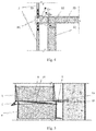
Fig. 5 is a schematic diagram of a preferred solution of the inter-story structure with a slideable prefabricated floorslab and a module inter-story damper as shown inFig. 2 ; -
Fig. 6 is a schematic diagram of setting the slideable prefabricated floorslab according to the preferred solution as shown inFig. 5 ; -
Fig 7 is a schematic diagram of a preferred solution of partial module piling of the structure as shown inFig. 1 ; -
Fig. 8 is a schematic diagram of an implementation solution of the dislocation piling in place of the structure as shown inFig. 1 ; and -
Fig. 9 is a schematic diagram of an implementation solution of the overhanging in place of the structure as shown inFig. 1 . - In the drawings, 1 refers to core tube structure, 2 refers to transfer story, 3 refers to module, 4 refers to hanging rod member, 5 refers to damper, 6 refers to diagonal supporting member, 7 refers to limiting buffer device, 8 refers to rod member, 9 refers to steel wire rope, 10 refers to ceiling beam, 11 refers to module column, 12 refers to stiffening rib, 13 refers to universal joint, 14 refers to T-shaped connecting steel plate, 15 refers to prefabricated floorslab, 16 refers to module inter-story damper, 17 refers to core tube floorslab, 18 refers to high-strength bolt, 19 refers to connecting steel plate, 20 refers to pre- buried channel steel, 21 refers to pre-buried contact steel plate, 22 refers to pre-buried anti-collision steel plate, 23 refers to pre-buried anchor bar, 24 refers to module group, 25 refers to lifting platform, and 26 refers to pre-buried connecting member.
- The present invention is further described hereinafter with reference to the drawings.
- A flexibly suspended modular building structure as shown in
Fig. 1 to Fig. 3 comprises a vertically arranged concrete core tube structure 1, wherein the core tube structure 1 is a key system to bear all horizontal loads and vertical loads of the whole structure, a transfer story 2 is arranged at the upper end of the core tube structure 1, multiple modules 3 with certain spaces reserved therebetween are hung below the transfer story 2, the modules 3 adjacent in the vertical direction are connected through a set of hanging rod members 4, the upper end of each hanging rod member 4 is pin- connected to a ceiling beam 5 located in the upper module 3, the lower end of each hanging rod member is pin- connected to a ceiling beam 5 located in the lower module 3, and the ceiling beam 5 is the beam located at the top surface of the module 3; and the hanging rod member 4 arranged on the uppermost modules 3 is pin- connected to the transfer story 2, dampers 5 are arranged between floors of all the modules 3 and the core tube structure, all the dampers 5 play a role of energy dissipation when the modules 3 and the core tube structure 1 move relatively, and the dampers 5 also have certain elastic stiffness to provide horizontal stiffness for the structure of the modules 3. A limiting buffer device 7 is arranged between the modules 3 adjacent in the vertical direction, and the limiting buffer device 7 is used for avoiding the modules 3 adjacent in the vertical direction from vertical colliding when the horizontal relative displacement is relatively large. Specifically, as shown inFig. 3 , the limiting buffer device 7 comprises two mutually connected rod members 8, the free end of each rod member 8 is respectively connected to the modules 3 adjacent in the vertical direction, wherein one rod member 8 is connected to a base angle located at the upper module 3, and the other rod member 8 is connected to a top angle located at the lower module 3 and adjacent to the upper module 3 in the vertical direction. A steel wire rope 9 is arranged between the two rod members 8, when the position between the rod members 8 is in an initial state, the steel wire rope 9 is in a relaxed state, the two rod members 8 and the steel wire rope 9 in a relaxed initial state form an "A-shaped" device, this A-shaped rod member group plays a role of leverage, which aims at reducing the elongation of the steel wire rope by scale to avoid the steel wire rope from being ruptured too early. The floor of each module 3 is connected to the core tube structure 1 through the damper 5, the damper 5 plays a main role of energy dissipation when the modules 3 and the core tube structure 1 move relatively, and the damper 5 has certain elastic stiffness to provide horizontal stiffness for the structure of the modules 3. In addition, when there is only a wind loading effect, since the damper plays a role of slide loading effect; the damper 5 does not slide, and can directly deliver the wind load to the core tube structure 1. As shown inFig. 4 , the ceiling beam 10 of the module is provided with an extended section outside a beam column node, the ceiling beam is provided with a stiffening rib 12 at a corresponding position, the hanging rod member 4 is a hollow circular steel tube generally, the end portion of the hanging rod member is connected to a universal joint 13, the universal joint 13 is connected to a web of a T-shaped connectingsteel plate 14 through a bolt, a flange of the T-shaped connectingsteel plate 14 is welded to the extended section of the ceiling beam 10 of the module, and the welding is conducted according to the requirement on rigid connection. The extended section of the ceiling beam of the module plays a role of allowing the hanging rod member 4 to swing in a certain range without collision. Each module 3 is internally provided with a diagonal supporting member 6, and the diagonal supporting member 6 strengthens the structure of the module from the interior. As shown inFig 5 , a slideable prefabricated floorslab 15 is arranged between each module 3 and the core tube structure 1, so as to keep the access of personnel while the module and the core tube structure move relatively. Channel steel 20 is pre-buried in the prefabricated floorslab 15, the Channel steel 20 before being pre-buried is connected to a connecting steel plate 19 through a high-strength bolt 18, the connecting steel plate 19 is welded to the beam column node at the floor of the module on site, the other end of the prefabricated floorslab 15 is placed on a groove of a core tube floorslab 17, and the two sides of a contact surface for placing are both provided with a pre-buried contact steel plate 21, which can form friction sliding. The vertical end face of the groove is provided with a pre-buried anti-collision steel plate 22, and all the pre-buried members above have a pre-buried anchor bar 23 welded thereon. A module inter-storydamper 16 is also arranged between two modules 3 adjacent in the vertical direction, the two ends of the module inter-storydamper 16 are respectively connected to the beam column node of the floor of the upper module 3 and the beam column node of the ceiling beam 5 of the lower module 3. - As shown in
Fig. 6 , as another preferred embodiment, a module group 24 piled up from bottom to top is arranged on a ground base set with a core tube structure mainly for the purpose of adjusting suspended mass ratio, the multiple modules piled up are mutually connected, the modules located at the ground base are mutually connected to the ground base, and the modules piled up are no more than four stories. - In order to provide exemplary embodiments, three installation methods of hanging section modules are described as follows:
- First method: aligned piling in place:
- 1. For the installation in place of a bottom platform: the function of the platform is to bear temporary vertical loads of modules on the platform. If the bottom of the structure is provided with a piling module, then the bottom module is directly installed.
- 2. After the module or the platform on a lower story is installed, a temporary block is installed, and the function of the temporary block is to reserve a vertical space, so that the module is not contacted in a vertical direction in a system formed finally; and after the temporary block is installed and leveled, the module of this story is lifted in place.
- 3. After the module of each story is installed in place subsequently, the hanging rod member and the limiting buffer device are installed, then the damper between the core tube structure and the module is installed, and other pipelines are connected.
- 4. The temporary block is withdrawn from the top to bottom, and the bottom platform is removed finally.
- Second method: dislocation piling in place, as shown in
Fig. 7 :- 1. For the installation in place of a lifting platform 25: the platform has a lifting device, and can be steadily and entirely lifted, with a small stroke required. The distance between the lifting platform 25 and the hanging transfer story is slightly larger than the height of the overall hanging section by subtracting the sum of the vertical space between the modules. That is to say, according to the solution that the modules are tightly piled up in the vertical direction without the temporary block, a distance with the transfer story is reserved as the operation space.
- 2. After the module or the platform on the lower story is installed, the module of this story is lifted in place, and the hanging rod member is connected. The modules at two storys are tightly piled up in the vertical direction to form certain dislocation in the horizontal direction, and the distance of the dislocation is determined according to the standard that the hanging rod member can be accurately connected.
- 3. After the module at each story is installed in place subsequently, the hanging rod member at the top story is installed, and then the lifting device of the bottom platform is used, so that the platform can decline steadily, until the module at the hanging end is naturally suspended. Then the platform is withdrawn.
- 4. The limiting buffer device is installed, the damper between the core tube structure and the module is installed, and other pipelines are connected.
- Third method: hanging in place, as shown in
Fig. 8 :- 1. The corresponding position of the core tube structure shall be provided with a pre-buried member 26, so that the module is temporarily suspended outside the core tube. The position of the pre-buried member at the top story is determined according to the standard that the pre-buried member can be accurately connected to the hanging rod member with the transfer story, and the position of the pre-buried member is calculated from top to bottom in sequence according to the standard.
- 2. The module is lifted by using the transfer story, the module at the top story is firstly lifted and installed, and is connected to the pre-buried member, and then the hanging rod is installed to form temporary fixation.
- 3. Step "2" is repeated in sequence from top to bottom.
- 4. The temporary fixation between the hanging modules and the pre-buried members at the top two stories is released to form a mechanism, so that the hanging modules and the pre-buried members are in place automatically under the effect of gravity, i.e., swinging to the corresponding positions horizontally. The limiting buffer device and the damper of the module at the top story are installed after being in place.
- 5. The temporary fixation of the modules of one story is released gradually from top to bottom, and after the modules are in place, the limiting buffer device and the damper of the module of the story above this story are installed.
- 6. The limiting buffer device and the damper of the module at the bottom story are installed, and other pipelines are connected.
- The contents above are only preferred embodiments of the invention. It shall be pointed out that those skilled in the art can make a plurality of improvements and polishing without departing from the principle of the invention, which shall also fall within the protection scope of the invention.
Claims (8)
- A flexibly suspended modular building structure, comprising a vertically arranged concrete core tube structure, wherein a transfer story is arranged at the upper end of the core tube structure, the transfer story is formed by a steel truss, connected to the concrete core tube, and cantilevered outside the core tube structure, multiple modules with certain spaces reserved therebetween are hung below the transfer story, the modules adjacent in the vertical direction are connected through a set of hanging rod members, the upper end of each hanging rod member is pin-connected to a ceiling beam located in the upper module, the lower end of each hanging rod member is pin-connected to a ceiling beam located in the lower module, the hanging rod member arranged on the uppermost module is pin-connected to the transfer story, and dampers are connected between floors of all the modules and the core tube structure.
- The flexibly suspended modular building structure according to claim 1, wherein a limiting buffer device is arranged between the modules adjacent in the vertical direction, and the limiting buffer device is used for avoiding the modules adjacent in the vertical direction from vertical colliding when the horizontal relative displacement is relatively large.
- The flexibly suspended modular building structure according to claim 2, wherein the limiting buffer device comprises two mutually connected rod members, the free end of each rod member is respectively connected to the modules adjacent in the vertical direction, wherein one rod member is connected to a base corner of the upper module, and the other rod member is connected to a top corner of the lower module, a steel wire rope is arranged between the two rod members, and when the position between the rod members is in an initial state, the steel wire rope is in a relaxed state.
- The flexibly suspended modular building structure according to claim 1, wherein the ceiling beam of each module is provided with an extended section outside a beam column joint, the end portion of the hanging rod member is connected to a universal joint, the universal joint is connected to a web of a T-shaped connecting steel plate, and a flange of the T-shaped connecting steel plate is welded with the extended section of the ceiling beam of the module.
- The flexibly suspended modular building structure according to claim 1, wherein a slideable prefabricated floorslab is arranged between each module and the core tube structure, one end of the prefabricated floorslab is connected to the beam column node at the floor of the module, and the other end of the prefabricated floorslab is placed on a floorslab of the core tube structure.
- The flexibly suspended modular building structure according to claim 5, wherein box iron is pre-buried in the prefabricated floorslab, the box iron is connected to a connecting steel plate bolt, the connecting steel plate is welded with the beam column joint at the floor level of the module, the other end of the prefabricated floorslab is placed on a groove of the floor of the core tube structure, and the two sides of a contact surface are provided with a pre-buried contact steel plate; the vertical end face of the groove is provided with a pre-buried anti-collision steel plate, and the contact steel plate and the anti-collision steel plate are welded on a pre-buried anchor bar of the prefabricated floorslab.
- The flexibly suspended modular building structure according to claim 1, wherein a module interlayer damper is connected between two modules adjacent in the vertical direction, the two ends of the module interlayer damper are respectively connected to the beam column joint of the floor of the upper module and the beam column joint of the ceiling of the lower module.
- The flexibly suspended modular building structure according to claim 1, wherein a module group consisting of multiple modules piled up from bottom to top is arranged on a ground base, the multiple modules piled up are mutually connected, the modules located at the ground base are connected to the ground base, and the modules piled up are no more than four stories.
Applications Claiming Priority (2)
| Application Number | Priority Date | Filing Date | Title |
|---|---|---|---|
| CN201610596905.9A CN106013452B (en) | 2016-07-26 | 2016-07-26 | A kind of flexible suspension formula building module structure |
| PCT/CN2017/078698 WO2018018913A1 (en) | 2016-07-26 | 2017-03-30 | Flexible hanging type module building structure |
Publications (3)
| Publication Number | Publication Date |
|---|---|
| EP3379002A1 true EP3379002A1 (en) | 2018-09-26 |
| EP3379002A4 EP3379002A4 (en) | 2019-02-20 |
| EP3379002B1 EP3379002B1 (en) | 2020-01-08 |
Family
ID=57114812
Family Applications (1)
| Application Number | Title | Priority Date | Filing Date |
|---|---|---|---|
| EP17833220.1A Active EP3379002B1 (en) | 2016-07-26 | 2017-03-30 | Flexible hanging type module building structure |
Country Status (3)
| Country | Link |
|---|---|
| EP (1) | EP3379002B1 (en) |
| CN (1) | CN106013452B (en) |
| WO (1) | WO2018018913A1 (en) |
Families Citing this family (33)
| Publication number | Priority date | Publication date | Assignee | Title |
|---|---|---|---|---|
| CN106013452B (en) * | 2016-07-26 | 2018-07-20 | 东南大学 | A kind of flexible suspension formula building module structure |
| CN106760139B (en) * | 2016-11-30 | 2023-09-22 | 广东省建筑设计研究院 | Externally-attached modularized building structure and construction method thereof |
| KR20180072034A (en) * | 2016-12-20 | 2018-06-29 | 단국대학교 산학협력단 | Damping system using space located outer staircase between main building |
| CN106869328A (en) * | 2017-03-07 | 2017-06-20 | 广东省建筑设计研究院 | A kind of suspension type modular architectural structural and its construction method |
| CN106996153B (en) * | 2017-05-16 | 2018-12-14 | 东南大学 | A kind of integral tension suspension |
| CN108442579B (en) * | 2018-04-16 | 2023-05-16 | 郑州中誉佳联实业有限公司 | Sliding node structure of prefabricated wall panel hung outside assembled wall body and installation method |
| CN108612199B (en) * | 2018-06-27 | 2023-12-19 | 威信广厦模块住宅工业有限公司 | Module building connection structure for steel structure core tube |
| CN109372097B (en) * | 2018-08-20 | 2023-10-20 | 筑友智造智能科技有限公司 | Assembled concrete truss building structure |
| CN109281390B (en) * | 2018-08-20 | 2023-10-20 | 筑友智造智能科技有限公司 | Assembled concrete truss shear wall building structure |
| CN109441088B (en) * | 2018-11-09 | 2024-03-22 | 上海建工二建集团有限公司 | Steel structure operation platform for super high-rise building core tube construction |
| CN109403459B (en) * | 2018-11-28 | 2020-07-24 | 东南大学 | Can realize folding assembled vertical cylinder suspended structure system that expandes quick construction |
| CN110886449B (en) * | 2019-11-19 | 2025-05-30 | 苏州金螳螂文化发展股份有限公司 | A wall concealed space wood veneer installation structure and method for reducing space occupation |
| CN111270867B (en) * | 2020-01-21 | 2021-12-17 | 山东大学 | Novel roof steel truss suspension assembly type elevator structure and construction method thereof |
| CN111677164B (en) * | 2020-06-27 | 2024-11-19 | 同济大学建筑设计研究院(集团)有限公司 | A connection node system with vertical sliding lateral restraint |
| CN111719699B (en) * | 2020-07-14 | 2021-08-03 | 东南大学建筑设计研究院有限公司 | Annular large-span suspension structure capable of releasing temperature effect |
| CN112095941B (en) * | 2020-09-10 | 2024-11-08 | 安徽新华学院 | A shock-absorbing assembled suspended staircase structure |
| CN113107092B (en) * | 2021-03-29 | 2022-11-22 | 中铁十二局集团建筑安装工程有限公司 | Overhung conversion construction method for super high-rise steel structure |
| CN113550475B (en) * | 2021-07-24 | 2022-09-06 | 江苏天力建设集团有限公司 | Prefabricated floor slab mounting structure |
| CN114703973A (en) * | 2021-12-08 | 2022-07-05 | 杭州圣建钢结构工程管理有限公司 | Suspension type building construction method |
| CN114607159B (en) * | 2022-01-24 | 2023-02-07 | 西南交通大学 | Design method of suspension type buffer type high-drop protection system for core tube construction |
| CN114411955B (en) * | 2022-03-09 | 2024-01-26 | 中建一局集团第三建筑有限公司 | Flexible connection structure of structural beam and constructional column |
| CN115467570B (en) * | 2022-08-15 | 2025-03-25 | 汕头大学 | A module-core tube structure with timely tuning and vibration reduction |
| CN115306037B (en) * | 2022-08-23 | 2024-01-16 | 中建一局集团华南建设有限公司 | Construction method of inclined core tube |
| CN115839147A (en) * | 2022-11-28 | 2023-03-24 | 中冶建工集团有限公司 | Embedded ceiling mounting structure and construction method thereof |
| CN116163411B (en) * | 2022-12-13 | 2025-11-04 | 悉地国际设计顾问(深圳)有限公司 | A diagonal grid building structure system |
| CN116005810B (en) * | 2022-12-30 | 2025-11-04 | 同济大学建筑设计研究院(集团)有限公司 | A combined steel truss and steel cable suspended building structure system and its construction method |
| CN116084565B (en) * | 2023-01-20 | 2025-11-04 | 悉地国际设计顾问(深圳)有限公司 | A space truss building structure system |
| CN115839130A (en) * | 2023-02-22 | 2023-03-24 | 湖南建设投资集团有限责任公司 | Sparse Steel Frame-Core Tube Modular Unit Housing Building Structural System |
| CN116971613B (en) * | 2023-09-13 | 2025-04-29 | 上海市机械施工集团有限公司 | Construction device and construction method for suspension steel structure |
| CN117432216A (en) * | 2023-09-27 | 2024-01-23 | 上海建工一建集团有限公司 | Multi-jack-up system cylinder column leveling synchronous construction comprehensive platform and its construction method |
| CN117418623B (en) * | 2023-09-28 | 2026-03-24 | 中建五局第三建设有限公司 | A cantilevered floor end suspension structure and its construction method |
| CN118639792B (en) * | 2024-08-07 | 2024-12-17 | 河南勤雄建筑工程有限公司 | Unsettled waterproof curtain wall construction of choosing |
| CN119711620B (en) * | 2025-01-15 | 2025-12-12 | 上海建工集团股份有限公司 | Core tube hanging type modularized building |
Family Cites Families (9)
| Publication number | Priority date | Publication date | Assignee | Title |
|---|---|---|---|---|
| DE3325783C1 (en) * | 1983-07-16 | 1984-09-13 | Polensky & Zöllner GmbH & Co., 6000 Frankfurt | building |
| JPS63315772A (en) * | 1987-06-19 | 1988-12-23 | 鹿島建設株式会社 | Earthquakeproof building |
| JP2541076B2 (en) * | 1992-06-17 | 1996-10-09 | 鹿島建設株式会社 | Building |
| AU2522595A (en) * | 1994-05-05 | 1995-11-29 | Eic Management Gmbh | Global vibro-compensating structural system (gvcs) for industrialized construction of vibro-isolated and seismo-resistant buildings |
| JP3890530B2 (en) * | 2002-10-22 | 2007-03-07 | 清水建設株式会社 | Twist prevention device |
| CN203285129U (en) * | 2013-05-31 | 2013-11-13 | 西南交通大学 | Damping high-rise building |
| CN204626734U (en) * | 2015-05-17 | 2015-09-09 | 陈斯乐 | Hang floor shock-damping structure |
| CN205917852U (en) * | 2016-07-26 | 2017-02-01 | 东南大学 | Flexible suspension type module building structure |
| CN106013452B (en) * | 2016-07-26 | 2018-07-20 | 东南大学 | A kind of flexible suspension formula building module structure |
-
2016
- 2016-07-26 CN CN201610596905.9A patent/CN106013452B/en active Active
-
2017
- 2017-03-30 EP EP17833220.1A patent/EP3379002B1/en active Active
- 2017-03-30 WO PCT/CN2017/078698 patent/WO2018018913A1/en not_active Ceased
Also Published As
| Publication number | Publication date |
|---|---|
| CN106013452B (en) | 2018-07-20 |
| CN106013452A (en) | 2016-10-12 |
| EP3379002A4 (en) | 2019-02-20 |
| WO2018018913A1 (en) | 2018-02-01 |
| EP3379002B1 (en) | 2020-01-08 |
Similar Documents
| Publication | Publication Date | Title |
|---|---|---|
| EP3379002B1 (en) | Flexible hanging type module building structure | |
| Saatcioglu et al. | Performance of reinforced concrete buildings during the 27 February 2010 Maule (Chile) earthquake | |
| CN205917852U (en) | Flexible suspension type module building structure | |
| CN118309177B (en) | High-rise modular buildings and construction methods combining mega-frames and partitioned infill modules | |
| CN214062435U (en) | Support system for high-altitude ultra-long cantilever structure | |
| KR20150138785A (en) | Vertical expansion remodeling method of existing building with seperate load path | |
| CN212507296U (en) | High formwork system | |
| US11339562B2 (en) | Area-covering structure module | |
| CN205476586U (en) | Power station underground factory building furred ceiling construction platform's interim support system | |
| CN205777531U (en) | Floor slab construction beam string shuttering supporting equipment | |
| CN112323978A (en) | Corner cantilever structure and building structure | |
| CN207063166U (en) | A kind of assembled Mixed Architecture suitable for high residential building | |
| CN214302807U (en) | Attached lifting scaffold supported by specially-made stand columns | |
| JP4914940B1 (en) | Middle-rise base-isolated building | |
| CN211597658U (en) | Movable overhanging scaffold | |
| CN103882882B (en) | Integral jacking formula tower crane platform structure | |
| CN219240972U (en) | Single-layer cable net curtain wall structure system | |
| CN218024833U (en) | Prefabricated elevator shaft | |
| CN207436536U (en) | Tower crane construction system | |
| CN210032222U (en) | Steel-concrete combined shear wall | |
| CN116044056A (en) | A Novel Viscoelastic Connected Steel Frame-Shear Wall Structure | |
| CN209942195U (en) | Construction operation platform of high-rise hollow area | |
| CN208039895U (en) | Steel reinforced concrete support underpins frame | |
| JP2000291287A (en) | Earthquake resistant building structure encircled by seismically isolated structure | |
| Mota | Voided" Two-Way" Flat Slabs |
Legal Events
| Date | Code | Title | Description |
|---|---|---|---|
| STAA | Information on the status of an ep patent application or granted ep patent |
Free format text: STATUS: THE INTERNATIONAL PUBLICATION HAS BEEN MADE |
|
| PUAI | Public reference made under article 153(3) epc to a published international application that has entered the european phase |
Free format text: ORIGINAL CODE: 0009012 |
|
| STAA | Information on the status of an ep patent application or granted ep patent |
Free format text: STATUS: REQUEST FOR EXAMINATION WAS MADE |
|
| 17P | Request for examination filed |
Effective date: 20180620 |
|
| AK | Designated contracting states |
Kind code of ref document: A1 Designated state(s): AL AT BE BG CH CY CZ DE DK EE ES FI FR GB GR HR HU IE IS IT LI LT LU LV MC MK MT NL NO PL PT RO RS SE SI SK SM TR |
|
| AX | Request for extension of the european patent |
Extension state: BA ME |
|
| A4 | Supplementary search report drawn up and despatched |
Effective date: 20181206 |
|
| RIC1 | Information provided on ipc code assigned before grant |
Ipc: E04H 9/02 20060101ALI20181130BHEP Ipc: E04B 1/34 20060101AFI20181130BHEP Ipc: E04B 1/38 20060101ALI20181130BHEP Ipc: E04B 1/98 20060101ALI20181130BHEP |
|
| RA4 | Supplementary search report drawn up and despatched (corrected) |
Effective date: 20181206 |
|
| RIC1 | Information provided on ipc code assigned before grant |
Ipc: E04B 1/98 20060101ALI20190114BHEP Ipc: E04B 1/38 20060101ALI20190114BHEP Ipc: E04B 1/34 20060101AFI20190114BHEP Ipc: E04H 9/02 20060101ALI20190114BHEP |
|
| DAV | Request for validation of the european patent (deleted) | ||
| DAX | Request for extension of the european patent (deleted) | ||
| GRAP | Despatch of communication of intention to grant a patent |
Free format text: ORIGINAL CODE: EPIDOSNIGR1 |
|
| STAA | Information on the status of an ep patent application or granted ep patent |
Free format text: STATUS: GRANT OF PATENT IS INTENDED |
|
| GRAS | Grant fee paid |
Free format text: ORIGINAL CODE: EPIDOSNIGR3 |
|
| INTG | Intention to grant announced |
Effective date: 20191105 |
|
| GRAA | (expected) grant |
Free format text: ORIGINAL CODE: 0009210 |
|
| STAA | Information on the status of an ep patent application or granted ep patent |
Free format text: STATUS: THE PATENT HAS BEEN GRANTED |
|
| AK | Designated contracting states |
Kind code of ref document: B1 Designated state(s): AL AT BE BG CH CY CZ DE DK EE ES FI FR GB GR HR HU IE IS IT LI LT LU LV MC MK MT NL NO PL PT RO RS SE SI SK SM TR |
|
| REG | Reference to a national code |
Ref country code: GB Ref legal event code: FG4D |
|
| REG | Reference to a national code |
Ref country code: CH Ref legal event code: EP |
|
| REG | Reference to a national code |
Ref country code: IE Ref legal event code: FG4D |
|
| REG | Reference to a national code |
Ref country code: DE Ref legal event code: R096 Ref document number: 602017010783 Country of ref document: DE |
|
| REG | Reference to a national code |
Ref country code: AT Ref legal event code: REF Ref document number: 1222886 Country of ref document: AT Kind code of ref document: T Effective date: 20200215 |
|
| REG | Reference to a national code |
Ref country code: NL Ref legal event code: MP Effective date: 20200108 |
|
| REG | Reference to a national code |
Ref country code: LT Ref legal event code: MG4D |
|
| PG25 | Lapsed in a contracting state [announced via postgrant information from national office to epo] |
Ref country code: NL Free format text: LAPSE BECAUSE OF FAILURE TO SUBMIT A TRANSLATION OF THE DESCRIPTION OR TO PAY THE FEE WITHIN THE PRESCRIBED TIME-LIMIT Effective date: 20200108 Ref country code: PT Free format text: LAPSE BECAUSE OF FAILURE TO SUBMIT A TRANSLATION OF THE DESCRIPTION OR TO PAY THE FEE WITHIN THE PRESCRIBED TIME-LIMIT Effective date: 20200531 Ref country code: RS Free format text: LAPSE BECAUSE OF FAILURE TO SUBMIT A TRANSLATION OF THE DESCRIPTION OR TO PAY THE FEE WITHIN THE PRESCRIBED TIME-LIMIT Effective date: 20200108 Ref country code: NO Free format text: LAPSE BECAUSE OF FAILURE TO SUBMIT A TRANSLATION OF THE DESCRIPTION OR TO PAY THE FEE WITHIN THE PRESCRIBED TIME-LIMIT Effective date: 20200408 Ref country code: FI Free format text: LAPSE BECAUSE OF FAILURE TO SUBMIT A TRANSLATION OF THE DESCRIPTION OR TO PAY THE FEE WITHIN THE PRESCRIBED TIME-LIMIT Effective date: 20200108 Ref country code: LT Free format text: LAPSE BECAUSE OF FAILURE TO SUBMIT A TRANSLATION OF THE DESCRIPTION OR TO PAY THE FEE WITHIN THE PRESCRIBED TIME-LIMIT Effective date: 20200108 |
|
| PG25 | Lapsed in a contracting state [announced via postgrant information from national office to epo] |
Ref country code: HR Free format text: LAPSE BECAUSE OF FAILURE TO SUBMIT A TRANSLATION OF THE DESCRIPTION OR TO PAY THE FEE WITHIN THE PRESCRIBED TIME-LIMIT Effective date: 20200108 Ref country code: LV Free format text: LAPSE BECAUSE OF FAILURE TO SUBMIT A TRANSLATION OF THE DESCRIPTION OR TO PAY THE FEE WITHIN THE PRESCRIBED TIME-LIMIT Effective date: 20200108 Ref country code: SE Free format text: LAPSE BECAUSE OF FAILURE TO SUBMIT A TRANSLATION OF THE DESCRIPTION OR TO PAY THE FEE WITHIN THE PRESCRIBED TIME-LIMIT Effective date: 20200108 Ref country code: IS Free format text: LAPSE BECAUSE OF FAILURE TO SUBMIT A TRANSLATION OF THE DESCRIPTION OR TO PAY THE FEE WITHIN THE PRESCRIBED TIME-LIMIT Effective date: 20200508 Ref country code: GR Free format text: LAPSE BECAUSE OF FAILURE TO SUBMIT A TRANSLATION OF THE DESCRIPTION OR TO PAY THE FEE WITHIN THE PRESCRIBED TIME-LIMIT Effective date: 20200409 Ref country code: BG Free format text: LAPSE BECAUSE OF FAILURE TO SUBMIT A TRANSLATION OF THE DESCRIPTION OR TO PAY THE FEE WITHIN THE PRESCRIBED TIME-LIMIT Effective date: 20200408 |
|
| REG | Reference to a national code |
Ref country code: DE Ref legal event code: R097 Ref document number: 602017010783 Country of ref document: DE |
|
| PG25 | Lapsed in a contracting state [announced via postgrant information from national office to epo] |
Ref country code: SM Free format text: LAPSE BECAUSE OF FAILURE TO SUBMIT A TRANSLATION OF THE DESCRIPTION OR TO PAY THE FEE WITHIN THE PRESCRIBED TIME-LIMIT Effective date: 20200108 Ref country code: SK Free format text: LAPSE BECAUSE OF FAILURE TO SUBMIT A TRANSLATION OF THE DESCRIPTION OR TO PAY THE FEE WITHIN THE PRESCRIBED TIME-LIMIT Effective date: 20200108 Ref country code: RO Free format text: LAPSE BECAUSE OF FAILURE TO SUBMIT A TRANSLATION OF THE DESCRIPTION OR TO PAY THE FEE WITHIN THE PRESCRIBED TIME-LIMIT Effective date: 20200108 Ref country code: CZ Free format text: LAPSE BECAUSE OF FAILURE TO SUBMIT A TRANSLATION OF THE DESCRIPTION OR TO PAY THE FEE WITHIN THE PRESCRIBED TIME-LIMIT Effective date: 20200108 Ref country code: ES Free format text: LAPSE BECAUSE OF FAILURE TO SUBMIT A TRANSLATION OF THE DESCRIPTION OR TO PAY THE FEE WITHIN THE PRESCRIBED TIME-LIMIT Effective date: 20200108 Ref country code: MC Free format text: LAPSE BECAUSE OF FAILURE TO SUBMIT A TRANSLATION OF THE DESCRIPTION OR TO PAY THE FEE WITHIN THE PRESCRIBED TIME-LIMIT Effective date: 20200108 Ref country code: DK Free format text: LAPSE BECAUSE OF FAILURE TO SUBMIT A TRANSLATION OF THE DESCRIPTION OR TO PAY THE FEE WITHIN THE PRESCRIBED TIME-LIMIT Effective date: 20200108 Ref country code: EE Free format text: LAPSE BECAUSE OF FAILURE TO SUBMIT A TRANSLATION OF THE DESCRIPTION OR TO PAY THE FEE WITHIN THE PRESCRIBED TIME-LIMIT Effective date: 20200108 |
|
| REG | Reference to a national code |
Ref country code: CH Ref legal event code: PL |
|
| PLBE | No opposition filed within time limit |
Free format text: ORIGINAL CODE: 0009261 |
|
| STAA | Information on the status of an ep patent application or granted ep patent |
Free format text: STATUS: NO OPPOSITION FILED WITHIN TIME LIMIT |
|
| REG | Reference to a national code |
Ref country code: AT Ref legal event code: MK05 Ref document number: 1222886 Country of ref document: AT Kind code of ref document: T Effective date: 20200108 |
|
| 26N | No opposition filed |
Effective date: 20201009 |
|
| REG | Reference to a national code |
Ref country code: BE Ref legal event code: MM Effective date: 20200331 |
|
| PG25 | Lapsed in a contracting state [announced via postgrant information from national office to epo] |
Ref country code: LU Free format text: LAPSE BECAUSE OF NON-PAYMENT OF DUE FEES Effective date: 20200330 |
|
| PG25 | Lapsed in a contracting state [announced via postgrant information from national office to epo] |
Ref country code: CH Free format text: LAPSE BECAUSE OF NON-PAYMENT OF DUE FEES Effective date: 20200331 Ref country code: AT Free format text: LAPSE BECAUSE OF FAILURE TO SUBMIT A TRANSLATION OF THE DESCRIPTION OR TO PAY THE FEE WITHIN THE PRESCRIBED TIME-LIMIT Effective date: 20200108 Ref country code: IE Free format text: LAPSE BECAUSE OF NON-PAYMENT OF DUE FEES Effective date: 20200330 Ref country code: LI Free format text: LAPSE BECAUSE OF NON-PAYMENT OF DUE FEES Effective date: 20200331 Ref country code: IT Free format text: LAPSE BECAUSE OF FAILURE TO SUBMIT A TRANSLATION OF THE DESCRIPTION OR TO PAY THE FEE WITHIN THE PRESCRIBED TIME-LIMIT Effective date: 20200108 |
|
| PG25 | Lapsed in a contracting state [announced via postgrant information from national office to epo] |
Ref country code: BE Free format text: LAPSE BECAUSE OF NON-PAYMENT OF DUE FEES Effective date: 20200331 Ref country code: SI Free format text: LAPSE BECAUSE OF FAILURE TO SUBMIT A TRANSLATION OF THE DESCRIPTION OR TO PAY THE FEE WITHIN THE PRESCRIBED TIME-LIMIT Effective date: 20200108 Ref country code: PL Free format text: LAPSE BECAUSE OF FAILURE TO SUBMIT A TRANSLATION OF THE DESCRIPTION OR TO PAY THE FEE WITHIN THE PRESCRIBED TIME-LIMIT Effective date: 20200108 |
|
| PG25 | Lapsed in a contracting state [announced via postgrant information from national office to epo] |
Ref country code: TR Free format text: LAPSE BECAUSE OF FAILURE TO SUBMIT A TRANSLATION OF THE DESCRIPTION OR TO PAY THE FEE WITHIN THE PRESCRIBED TIME-LIMIT Effective date: 20200108 Ref country code: MT Free format text: LAPSE BECAUSE OF FAILURE TO SUBMIT A TRANSLATION OF THE DESCRIPTION OR TO PAY THE FEE WITHIN THE PRESCRIBED TIME-LIMIT Effective date: 20200108 Ref country code: CY Free format text: LAPSE BECAUSE OF FAILURE TO SUBMIT A TRANSLATION OF THE DESCRIPTION OR TO PAY THE FEE WITHIN THE PRESCRIBED TIME-LIMIT Effective date: 20200108 |
|
| PG25 | Lapsed in a contracting state [announced via postgrant information from national office to epo] |
Ref country code: MK Free format text: LAPSE BECAUSE OF FAILURE TO SUBMIT A TRANSLATION OF THE DESCRIPTION OR TO PAY THE FEE WITHIN THE PRESCRIBED TIME-LIMIT Effective date: 20200108 Ref country code: AL Free format text: LAPSE BECAUSE OF FAILURE TO SUBMIT A TRANSLATION OF THE DESCRIPTION OR TO PAY THE FEE WITHIN THE PRESCRIBED TIME-LIMIT Effective date: 20200108 |
|
| PGFP | Annual fee paid to national office [announced via postgrant information from national office to epo] |
Ref country code: GB Payment date: 20260323 Year of fee payment: 10 |
|
| PGFP | Annual fee paid to national office [announced via postgrant information from national office to epo] |
Ref country code: DE Payment date: 20260313 Year of fee payment: 10 |
|
| PGFP | Annual fee paid to national office [announced via postgrant information from national office to epo] |
Ref country code: FR Payment date: 20260330 Year of fee payment: 10 |