EP3378799B1 - Tabbed sealing member - Google Patents
Tabbed sealing member Download PDFInfo
- Publication number
- EP3378799B1 EP3378799B1 EP18171446.0A EP18171446A EP3378799B1 EP 3378799 B1 EP3378799 B1 EP 3378799B1 EP 18171446 A EP18171446 A EP 18171446A EP 3378799 B1 EP3378799 B1 EP 3378799B1
- Authority
- EP
- European Patent Office
- Prior art keywords
- layer
- tab
- sealing member
- seal
- laminate
- Prior art date
- Legal status (The legal status is an assumption and is not a legal conclusion. Google has not performed a legal analysis and makes no representation as to the accuracy of the status listed.)
- Active
Links
- 238000007789 sealing Methods 0.000 title claims description 170
- 229920000642 polymer Polymers 0.000 claims description 76
- 239000006260 foam Substances 0.000 claims description 66
- 239000000853 adhesive Substances 0.000 claims description 26
- 230000001070 adhesive effect Effects 0.000 claims description 26
- 238000010438 heat treatment Methods 0.000 claims description 26
- 239000011888 foil Substances 0.000 claims description 20
- 229910052751 metal Inorganic materials 0.000 claims description 18
- 239000002184 metal Substances 0.000 claims description 18
- 239000005038 ethylene vinyl acetate Substances 0.000 claims description 15
- DQXBYHZEEUGOBF-UHFFFAOYSA-N but-3-enoic acid;ethene Chemical compound C=C.OC(=O)CC=C DQXBYHZEEUGOBF-UHFFFAOYSA-N 0.000 claims description 11
- 229920001200 poly(ethylene-vinyl acetate) Polymers 0.000 claims description 11
- 229920000098 polyolefin Polymers 0.000 claims description 11
- 229920001577 copolymer Polymers 0.000 claims description 7
- 229920006242 ethylene acrylic acid copolymer Polymers 0.000 claims description 7
- JOYRKODLDBILNP-UHFFFAOYSA-N Ethyl urethane Chemical compound CCOC(N)=O JOYRKODLDBILNP-UHFFFAOYSA-N 0.000 claims description 5
- 229920006332 epoxy adhesive Polymers 0.000 claims description 5
- 229920002635 polyurethane Polymers 0.000 claims description 5
- 239000004814 polyurethane Substances 0.000 claims description 5
- 229910052782 aluminium Inorganic materials 0.000 claims description 3
- XAGFODPZIPBFFR-UHFFFAOYSA-N aluminium Chemical compound [Al] XAGFODPZIPBFFR-UHFFFAOYSA-N 0.000 claims description 3
- 239000010410 layer Substances 0.000 description 343
- 238000013459 approach Methods 0.000 description 108
- 239000000463 material Substances 0.000 description 33
- 239000001993 wax Substances 0.000 description 32
- 230000006698 induction Effects 0.000 description 31
- 229920000728 polyester Polymers 0.000 description 21
- 238000000034 method Methods 0.000 description 17
- 239000000123 paper Substances 0.000 description 17
- 230000008569 process Effects 0.000 description 15
- 239000011324 bead Substances 0.000 description 14
- 239000012790 adhesive layer Substances 0.000 description 12
- 239000012528 membrane Substances 0.000 description 10
- 238000009413 insulation Methods 0.000 description 9
- -1 polyethylene Polymers 0.000 description 9
- 239000000203 mixture Substances 0.000 description 8
- 230000002093 peripheral effect Effects 0.000 description 7
- 239000002131 composite material Substances 0.000 description 6
- 238000002844 melting Methods 0.000 description 6
- 230000008018 melting Effects 0.000 description 6
- 239000004200 microcrystalline wax Substances 0.000 description 6
- 235000019808 microcrystalline wax Nutrition 0.000 description 6
- 238000012546 transfer Methods 0.000 description 6
- 239000004677 Nylon Substances 0.000 description 5
- 239000004743 Polypropylene Substances 0.000 description 5
- 238000010276 construction Methods 0.000 description 5
- 229920001778 nylon Polymers 0.000 description 5
- 229920001155 polypropylene Polymers 0.000 description 5
- XTXRWKRVRITETP-UHFFFAOYSA-N Vinyl acetate Chemical compound CC(=O)OC=C XTXRWKRVRITETP-UHFFFAOYSA-N 0.000 description 4
- 238000000576 coating method Methods 0.000 description 4
- 229920001684 low density polyethylene Polymers 0.000 description 4
- 239000004702 low-density polyethylene Substances 0.000 description 4
- 239000000155 melt Substances 0.000 description 4
- 239000004698 Polyethylene Substances 0.000 description 3
- 230000004888 barrier function Effects 0.000 description 3
- 239000003795 chemical substances by application Substances 0.000 description 3
- 239000011248 coating agent Substances 0.000 description 3
- 229920000573 polyethylene Polymers 0.000 description 3
- 239000000565 sealant Substances 0.000 description 3
- 238000000926 separation method Methods 0.000 description 3
- VGGSQFUCUMXWEO-UHFFFAOYSA-N Ethene Chemical compound C=C VGGSQFUCUMXWEO-UHFFFAOYSA-N 0.000 description 2
- 239000005977 Ethylene Substances 0.000 description 2
- 239000004831 Hot glue Substances 0.000 description 2
- 230000008901 benefit Effects 0.000 description 2
- 239000000835 fiber Substances 0.000 description 2
- 238000004519 manufacturing process Methods 0.000 description 2
- 239000000178 monomer Substances 0.000 description 2
- 239000012188 paraffin wax Substances 0.000 description 2
- 229920000139 polyethylene terephthalate Polymers 0.000 description 2
- 239000005020 polyethylene terephthalate Substances 0.000 description 2
- 239000002861 polymer material Substances 0.000 description 2
- 229920002994 synthetic fiber Polymers 0.000 description 2
- 230000037303 wrinkles Effects 0.000 description 2
- 229920002367 Polyisobutene Polymers 0.000 description 1
- 239000004793 Polystyrene Substances 0.000 description 1
- 239000004820 Pressure-sensitive adhesive Substances 0.000 description 1
- 229920003182 Surlyn® Polymers 0.000 description 1
- ATJFFYVFTNAWJD-UHFFFAOYSA-N Tin Chemical compound [Sn] ATJFFYVFTNAWJD-UHFFFAOYSA-N 0.000 description 1
- 239000011358 absorbing material Substances 0.000 description 1
- 230000004913 activation Effects 0.000 description 1
- 239000000654 additive Substances 0.000 description 1
- 239000002313 adhesive film Substances 0.000 description 1
- 230000000712 assembly Effects 0.000 description 1
- 238000000429 assembly Methods 0.000 description 1
- 230000015572 biosynthetic process Effects 0.000 description 1
- 229920002678 cellulose Polymers 0.000 description 1
- 239000001913 cellulose Substances 0.000 description 1
- 230000006835 compression Effects 0.000 description 1
- 238000007906 compression Methods 0.000 description 1
- 239000012792 core layer Substances 0.000 description 1
- 230000007423 decrease Effects 0.000 description 1
- 230000006866 deterioration Effects 0.000 description 1
- 230000002542 deteriorative effect Effects 0.000 description 1
- 210000004905 finger nail Anatomy 0.000 description 1
- 238000005187 foaming Methods 0.000 description 1
- 239000007789 gas Substances 0.000 description 1
- 230000005012 migration Effects 0.000 description 1
- 238000013508 migration Methods 0.000 description 1
- 229920003023 plastic Polymers 0.000 description 1
- 239000004033 plastic Substances 0.000 description 1
- 229920006267 polyester film Polymers 0.000 description 1
- 229920006254 polymer film Polymers 0.000 description 1
- 229920001296 polysiloxane Polymers 0.000 description 1
- 239000011148 porous material Substances 0.000 description 1
- 238000012545 processing Methods 0.000 description 1
- 238000004080 punching Methods 0.000 description 1
- 230000000717 retained effect Effects 0.000 description 1
- 230000000979 retarding effect Effects 0.000 description 1
- 230000011218 segmentation Effects 0.000 description 1
- 239000002356 single layer Substances 0.000 description 1
- 230000007847 structural defect Effects 0.000 description 1
- 239000012209 synthetic fiber Substances 0.000 description 1
Images


Classifications
-
- B—PERFORMING OPERATIONS; TRANSPORTING
- B65—CONVEYING; PACKING; STORING; HANDLING THIN OR FILAMENTARY MATERIAL
- B65D—CONTAINERS FOR STORAGE OR TRANSPORT OF ARTICLES OR MATERIALS, e.g. BAGS, BARRELS, BOTTLES, BOXES, CANS, CARTONS, CRATES, DRUMS, JARS, TANKS, HOPPERS, FORWARDING CONTAINERS; ACCESSORIES, CLOSURES, OR FITTINGS THEREFOR; PACKAGING ELEMENTS; PACKAGES
- B65D17/00—Rigid or semi-rigid containers specially constructed to be opened by cutting or piercing, or by tearing of frangible members or portions
- B65D17/50—Non-integral frangible members applied to, or inserted in, preformed openings, e.g. tearable strips or plastic plugs
- B65D17/501—Flexible tape or foil-like material
-
- B—PERFORMING OPERATIONS; TRANSPORTING
- B65—CONVEYING; PACKING; STORING; HANDLING THIN OR FILAMENTARY MATERIAL
- B65D—CONTAINERS FOR STORAGE OR TRANSPORT OF ARTICLES OR MATERIALS, e.g. BAGS, BARRELS, BOTTLES, BOXES, CANS, CARTONS, CRATES, DRUMS, JARS, TANKS, HOPPERS, FORWARDING CONTAINERS; ACCESSORIES, CLOSURES, OR FITTINGS THEREFOR; PACKAGING ELEMENTS; PACKAGES
- B65D53/00—Sealing or packing elements; Sealings formed by liquid or plastics material
- B65D53/04—Discs
-
- B—PERFORMING OPERATIONS; TRANSPORTING
- B65—CONVEYING; PACKING; STORING; HANDLING THIN OR FILAMENTARY MATERIAL
- B65D—CONTAINERS FOR STORAGE OR TRANSPORT OF ARTICLES OR MATERIALS, e.g. BAGS, BARRELS, BOTTLES, BOXES, CANS, CARTONS, CRATES, DRUMS, JARS, TANKS, HOPPERS, FORWARDING CONTAINERS; ACCESSORIES, CLOSURES, OR FITTINGS THEREFOR; PACKAGING ELEMENTS; PACKAGES
- B65D55/00—Accessories for container closures not otherwise provided for
- B65D55/02—Locking devices; Means for discouraging or indicating unauthorised opening or removal of closure
- B65D55/06—Deformable or tearable wires, strings, or strips; Use of seals, e.g. destructible locking pins
-
- B—PERFORMING OPERATIONS; TRANSPORTING
- B32—LAYERED PRODUCTS
- B32B—LAYERED PRODUCTS, i.e. PRODUCTS BUILT-UP OF STRATA OF FLAT OR NON-FLAT, e.g. CELLULAR OR HONEYCOMB, FORM
- B32B15/00—Layered products comprising a layer of metal
- B32B15/04—Layered products comprising a layer of metal comprising metal as the main or only constituent of a layer, which is next to another layer of the same or of a different material
- B32B15/046—Layered products comprising a layer of metal comprising metal as the main or only constituent of a layer, which is next to another layer of the same or of a different material of foam
-
- B—PERFORMING OPERATIONS; TRANSPORTING
- B32—LAYERED PRODUCTS
- B32B—LAYERED PRODUCTS, i.e. PRODUCTS BUILT-UP OF STRATA OF FLAT OR NON-FLAT, e.g. CELLULAR OR HONEYCOMB, FORM
- B32B15/00—Layered products comprising a layer of metal
- B32B15/04—Layered products comprising a layer of metal comprising metal as the main or only constituent of a layer, which is next to another layer of the same or of a different material
- B32B15/08—Layered products comprising a layer of metal comprising metal as the main or only constituent of a layer, which is next to another layer of the same or of a different material of synthetic resin
- B32B15/085—Layered products comprising a layer of metal comprising metal as the main or only constituent of a layer, which is next to another layer of the same or of a different material of synthetic resin comprising polyolefins
-
- B—PERFORMING OPERATIONS; TRANSPORTING
- B32—LAYERED PRODUCTS
- B32B—LAYERED PRODUCTS, i.e. PRODUCTS BUILT-UP OF STRATA OF FLAT OR NON-FLAT, e.g. CELLULAR OR HONEYCOMB, FORM
- B32B15/00—Layered products comprising a layer of metal
- B32B15/04—Layered products comprising a layer of metal comprising metal as the main or only constituent of a layer, which is next to another layer of the same or of a different material
- B32B15/08—Layered products comprising a layer of metal comprising metal as the main or only constituent of a layer, which is next to another layer of the same or of a different material of synthetic resin
- B32B15/09—Layered products comprising a layer of metal comprising metal as the main or only constituent of a layer, which is next to another layer of the same or of a different material of synthetic resin comprising polyesters
-
- B—PERFORMING OPERATIONS; TRANSPORTING
- B32—LAYERED PRODUCTS
- B32B—LAYERED PRODUCTS, i.e. PRODUCTS BUILT-UP OF STRATA OF FLAT OR NON-FLAT, e.g. CELLULAR OR HONEYCOMB, FORM
- B32B15/00—Layered products comprising a layer of metal
- B32B15/14—Layered products comprising a layer of metal next to a fibrous or filamentary layer
-
- B—PERFORMING OPERATIONS; TRANSPORTING
- B32—LAYERED PRODUCTS
- B32B—LAYERED PRODUCTS, i.e. PRODUCTS BUILT-UP OF STRATA OF FLAT OR NON-FLAT, e.g. CELLULAR OR HONEYCOMB, FORM
- B32B15/00—Layered products comprising a layer of metal
- B32B15/20—Layered products comprising a layer of metal comprising aluminium or copper
-
- B—PERFORMING OPERATIONS; TRANSPORTING
- B32—LAYERED PRODUCTS
- B32B—LAYERED PRODUCTS, i.e. PRODUCTS BUILT-UP OF STRATA OF FLAT OR NON-FLAT, e.g. CELLULAR OR HONEYCOMB, FORM
- B32B27/00—Layered products comprising a layer of synthetic resin
- B32B27/06—Layered products comprising a layer of synthetic resin as the main or only constituent of a layer, which is next to another layer of the same or of a different material
- B32B27/065—Layered products comprising a layer of synthetic resin as the main or only constituent of a layer, which is next to another layer of the same or of a different material of foam
-
- B—PERFORMING OPERATIONS; TRANSPORTING
- B32—LAYERED PRODUCTS
- B32B—LAYERED PRODUCTS, i.e. PRODUCTS BUILT-UP OF STRATA OF FLAT OR NON-FLAT, e.g. CELLULAR OR HONEYCOMB, FORM
- B32B27/00—Layered products comprising a layer of synthetic resin
- B32B27/06—Layered products comprising a layer of synthetic resin as the main or only constituent of a layer, which is next to another layer of the same or of a different material
- B32B27/08—Layered products comprising a layer of synthetic resin as the main or only constituent of a layer, which is next to another layer of the same or of a different material of synthetic resin
-
- B—PERFORMING OPERATIONS; TRANSPORTING
- B32—LAYERED PRODUCTS
- B32B—LAYERED PRODUCTS, i.e. PRODUCTS BUILT-UP OF STRATA OF FLAT OR NON-FLAT, e.g. CELLULAR OR HONEYCOMB, FORM
- B32B27/00—Layered products comprising a layer of synthetic resin
- B32B27/12—Layered products comprising a layer of synthetic resin next to a fibrous or filamentary layer
-
- B—PERFORMING OPERATIONS; TRANSPORTING
- B32—LAYERED PRODUCTS
- B32B—LAYERED PRODUCTS, i.e. PRODUCTS BUILT-UP OF STRATA OF FLAT OR NON-FLAT, e.g. CELLULAR OR HONEYCOMB, FORM
- B32B27/00—Layered products comprising a layer of synthetic resin
- B32B27/32—Layered products comprising a layer of synthetic resin comprising polyolefins
-
- B—PERFORMING OPERATIONS; TRANSPORTING
- B32—LAYERED PRODUCTS
- B32B—LAYERED PRODUCTS, i.e. PRODUCTS BUILT-UP OF STRATA OF FLAT OR NON-FLAT, e.g. CELLULAR OR HONEYCOMB, FORM
- B32B27/00—Layered products comprising a layer of synthetic resin
- B32B27/36—Layered products comprising a layer of synthetic resin comprising polyesters
-
- B—PERFORMING OPERATIONS; TRANSPORTING
- B32—LAYERED PRODUCTS
- B32B—LAYERED PRODUCTS, i.e. PRODUCTS BUILT-UP OF STRATA OF FLAT OR NON-FLAT, e.g. CELLULAR OR HONEYCOMB, FORM
- B32B33/00—Layered products characterised by particular properties or particular surface features, e.g. particular surface coatings; Layered products designed for particular purposes not covered by another single class
-
- B—PERFORMING OPERATIONS; TRANSPORTING
- B32—LAYERED PRODUCTS
- B32B—LAYERED PRODUCTS, i.e. PRODUCTS BUILT-UP OF STRATA OF FLAT OR NON-FLAT, e.g. CELLULAR OR HONEYCOMB, FORM
- B32B5/00—Layered products characterised by the non- homogeneity or physical structure, i.e. comprising a fibrous, filamentary, particulate or foam layer; Layered products characterised by having a layer differing constitutionally or physically in different parts
- B32B5/22—Layered products characterised by the non- homogeneity or physical structure, i.e. comprising a fibrous, filamentary, particulate or foam layer; Layered products characterised by having a layer differing constitutionally or physically in different parts characterised by the presence of two or more layers which are next to each other and are fibrous, filamentary, formed of particles or foamed
- B32B5/24—Layered products characterised by the non- homogeneity or physical structure, i.e. comprising a fibrous, filamentary, particulate or foam layer; Layered products characterised by having a layer differing constitutionally or physically in different parts characterised by the presence of two or more layers which are next to each other and are fibrous, filamentary, formed of particles or foamed one layer being a fibrous or filamentary layer
- B32B5/245—Layered products characterised by the non- homogeneity or physical structure, i.e. comprising a fibrous, filamentary, particulate or foam layer; Layered products characterised by having a layer differing constitutionally or physically in different parts characterised by the presence of two or more layers which are next to each other and are fibrous, filamentary, formed of particles or foamed one layer being a fibrous or filamentary layer another layer next to it being a foam layer
-
- B—PERFORMING OPERATIONS; TRANSPORTING
- B32—LAYERED PRODUCTS
- B32B—LAYERED PRODUCTS, i.e. PRODUCTS BUILT-UP OF STRATA OF FLAT OR NON-FLAT, e.g. CELLULAR OR HONEYCOMB, FORM
- B32B7/00—Layered products characterised by the relation between layers; Layered products characterised by the relative orientation of features between layers, or by the relative values of a measurable parameter between layers, i.e. products comprising layers having different physical, chemical or physicochemical properties; Layered products characterised by the interconnection of layers
- B32B7/04—Interconnection of layers
- B32B7/12—Interconnection of layers using interposed adhesives or interposed materials with bonding properties
-
- B—PERFORMING OPERATIONS; TRANSPORTING
- B65—CONVEYING; PACKING; STORING; HANDLING THIN OR FILAMENTARY MATERIAL
- B65D—CONTAINERS FOR STORAGE OR TRANSPORT OF ARTICLES OR MATERIALS, e.g. BAGS, BARRELS, BOTTLES, BOXES, CANS, CARTONS, CRATES, DRUMS, JARS, TANKS, HOPPERS, FORWARDING CONTAINERS; ACCESSORIES, CLOSURES, OR FITTINGS THEREFOR; PACKAGING ELEMENTS; PACKAGES
- B65D17/00—Rigid or semi-rigid containers specially constructed to be opened by cutting or piercing, or by tearing of frangible members or portions
- B65D17/50—Non-integral frangible members applied to, or inserted in, preformed openings, e.g. tearable strips or plastic plugs
-
- B—PERFORMING OPERATIONS; TRANSPORTING
- B65—CONVEYING; PACKING; STORING; HANDLING THIN OR FILAMENTARY MATERIAL
- B65D—CONTAINERS FOR STORAGE OR TRANSPORT OF ARTICLES OR MATERIALS, e.g. BAGS, BARRELS, BOTTLES, BOXES, CANS, CARTONS, CRATES, DRUMS, JARS, TANKS, HOPPERS, FORWARDING CONTAINERS; ACCESSORIES, CLOSURES, OR FITTINGS THEREFOR; PACKAGING ELEMENTS; PACKAGES
- B65D43/00—Lids or covers for rigid or semi-rigid containers
- B65D43/02—Removable lids or covers
-
- B—PERFORMING OPERATIONS; TRANSPORTING
- B65—CONVEYING; PACKING; STORING; HANDLING THIN OR FILAMENTARY MATERIAL
- B65D—CONTAINERS FOR STORAGE OR TRANSPORT OF ARTICLES OR MATERIALS, e.g. BAGS, BARRELS, BOTTLES, BOXES, CANS, CARTONS, CRATES, DRUMS, JARS, TANKS, HOPPERS, FORWARDING CONTAINERS; ACCESSORIES, CLOSURES, OR FITTINGS THEREFOR; PACKAGING ELEMENTS; PACKAGES
- B65D51/00—Closures not otherwise provided for
- B65D51/005—Closures provided with linings or internal coatings so as to avoid contact of the closure with the contents
-
- B—PERFORMING OPERATIONS; TRANSPORTING
- B65—CONVEYING; PACKING; STORING; HANDLING THIN OR FILAMENTARY MATERIAL
- B65D—CONTAINERS FOR STORAGE OR TRANSPORT OF ARTICLES OR MATERIALS, e.g. BAGS, BARRELS, BOTTLES, BOXES, CANS, CARTONS, CRATES, DRUMS, JARS, TANKS, HOPPERS, FORWARDING CONTAINERS; ACCESSORIES, CLOSURES, OR FITTINGS THEREFOR; PACKAGING ELEMENTS; PACKAGES
- B65D51/00—Closures not otherwise provided for
- B65D51/18—Arrangements of closures with protective outer cap-like covers or of two or more co-operating closures
- B65D51/20—Caps, lids, or covers co-operating with an inner closure arranged to be opened by piercing, cutting, or tearing
-
- B—PERFORMING OPERATIONS; TRANSPORTING
- B65—CONVEYING; PACKING; STORING; HANDLING THIN OR FILAMENTARY MATERIAL
- B65D—CONTAINERS FOR STORAGE OR TRANSPORT OF ARTICLES OR MATERIALS, e.g. BAGS, BARRELS, BOTTLES, BOXES, CANS, CARTONS, CRATES, DRUMS, JARS, TANKS, HOPPERS, FORWARDING CONTAINERS; ACCESSORIES, CLOSURES, OR FITTINGS THEREFOR; PACKAGING ELEMENTS; PACKAGES
- B65D77/00—Packages formed by enclosing articles or materials in preformed containers, e.g. boxes, cartons, sacks or bags
- B65D77/10—Container closures formed after filling
- B65D77/20—Container closures formed after filling by applying separate lids or covers, i.e. flexible membrane or foil-like covers
- B65D77/2024—Container closures formed after filling by applying separate lids or covers, i.e. flexible membrane or foil-like covers the cover being welded or adhered to the container
- B65D77/2028—Means for opening the cover other than, or in addition to, a pull tab
- B65D77/2032—Means for opening the cover other than, or in addition to, a pull tab by peeling or tearing the cover from the container
- B65D77/2044—Means for opening the cover other than, or in addition to, a pull tab by peeling or tearing the cover from the container whereby a layer of the container or cover fails, e.g. cohesive failure
-
- B—PERFORMING OPERATIONS; TRANSPORTING
- B32—LAYERED PRODUCTS
- B32B—LAYERED PRODUCTS, i.e. PRODUCTS BUILT-UP OF STRATA OF FLAT OR NON-FLAT, e.g. CELLULAR OR HONEYCOMB, FORM
- B32B2262/00—Composition or structural features of fibres which form a fibrous or filamentary layer or are present as additives
- B32B2262/02—Synthetic macromolecular fibres
- B32B2262/0261—Polyamide fibres
-
- B—PERFORMING OPERATIONS; TRANSPORTING
- B32—LAYERED PRODUCTS
- B32B—LAYERED PRODUCTS, i.e. PRODUCTS BUILT-UP OF STRATA OF FLAT OR NON-FLAT, e.g. CELLULAR OR HONEYCOMB, FORM
- B32B2266/00—Composition of foam
- B32B2266/02—Organic
- B32B2266/0214—Materials belonging to B32B27/00
- B32B2266/025—Polyolefin
-
- B—PERFORMING OPERATIONS; TRANSPORTING
- B32—LAYERED PRODUCTS
- B32B—LAYERED PRODUCTS, i.e. PRODUCTS BUILT-UP OF STRATA OF FLAT OR NON-FLAT, e.g. CELLULAR OR HONEYCOMB, FORM
- B32B2266/00—Composition of foam
- B32B2266/02—Organic
- B32B2266/0214—Materials belonging to B32B27/00
- B32B2266/0264—Polyester
-
- B—PERFORMING OPERATIONS; TRANSPORTING
- B32—LAYERED PRODUCTS
- B32B—LAYERED PRODUCTS, i.e. PRODUCTS BUILT-UP OF STRATA OF FLAT OR NON-FLAT, e.g. CELLULAR OR HONEYCOMB, FORM
- B32B2435/00—Closures, end caps, stoppers
- B32B2435/02—Closures, end caps, stoppers for containers
-
- B—PERFORMING OPERATIONS; TRANSPORTING
- B65—CONVEYING; PACKING; STORING; HANDLING THIN OR FILAMENTARY MATERIAL
- B65D—CONTAINERS FOR STORAGE OR TRANSPORT OF ARTICLES OR MATERIALS, e.g. BAGS, BARRELS, BOTTLES, BOXES, CANS, CARTONS, CRATES, DRUMS, JARS, TANKS, HOPPERS, FORWARDING CONTAINERS; ACCESSORIES, CLOSURES, OR FITTINGS THEREFOR; PACKAGING ELEMENTS; PACKAGES
- B65D2251/00—Details relating to container closures
- B65D2251/0003—Two or more closures
- B65D2251/0006—Upper closure
- B65D2251/0009—Upper closure of the 17-type
-
- B—PERFORMING OPERATIONS; TRANSPORTING
- B65—CONVEYING; PACKING; STORING; HANDLING THIN OR FILAMENTARY MATERIAL
- B65D—CONTAINERS FOR STORAGE OR TRANSPORT OF ARTICLES OR MATERIALS, e.g. BAGS, BARRELS, BOTTLES, BOXES, CANS, CARTONS, CRATES, DRUMS, JARS, TANKS, HOPPERS, FORWARDING CONTAINERS; ACCESSORIES, CLOSURES, OR FITTINGS THEREFOR; PACKAGING ELEMENTS; PACKAGES
- B65D2251/00—Details relating to container closures
- B65D2251/0003—Two or more closures
- B65D2251/0006—Upper closure
- B65D2251/0015—Upper closure of the 41-type
-
- B—PERFORMING OPERATIONS; TRANSPORTING
- B65—CONVEYING; PACKING; STORING; HANDLING THIN OR FILAMENTARY MATERIAL
- B65D—CONTAINERS FOR STORAGE OR TRANSPORT OF ARTICLES OR MATERIALS, e.g. BAGS, BARRELS, BOTTLES, BOXES, CANS, CARTONS, CRATES, DRUMS, JARS, TANKS, HOPPERS, FORWARDING CONTAINERS; ACCESSORIES, CLOSURES, OR FITTINGS THEREFOR; PACKAGING ELEMENTS; PACKAGES
- B65D2251/00—Details relating to container closures
- B65D2251/0003—Two or more closures
- B65D2251/0006—Upper closure
- B65D2251/0018—Upper closure of the 43-type
-
- B—PERFORMING OPERATIONS; TRANSPORTING
- B65—CONVEYING; PACKING; STORING; HANDLING THIN OR FILAMENTARY MATERIAL
- B65D—CONTAINERS FOR STORAGE OR TRANSPORT OF ARTICLES OR MATERIALS, e.g. BAGS, BARRELS, BOTTLES, BOXES, CANS, CARTONS, CRATES, DRUMS, JARS, TANKS, HOPPERS, FORWARDING CONTAINERS; ACCESSORIES, CLOSURES, OR FITTINGS THEREFOR; PACKAGING ELEMENTS; PACKAGES
- B65D2251/00—Details relating to container closures
- B65D2251/0003—Two or more closures
- B65D2251/0006—Upper closure
- B65D2251/0028—Upper closure of the 51-type
-
- B—PERFORMING OPERATIONS; TRANSPORTING
- B65—CONVEYING; PACKING; STORING; HANDLING THIN OR FILAMENTARY MATERIAL
- B65D—CONTAINERS FOR STORAGE OR TRANSPORT OF ARTICLES OR MATERIALS, e.g. BAGS, BARRELS, BOTTLES, BOXES, CANS, CARTONS, CRATES, DRUMS, JARS, TANKS, HOPPERS, FORWARDING CONTAINERS; ACCESSORIES, CLOSURES, OR FITTINGS THEREFOR; PACKAGING ELEMENTS; PACKAGES
- B65D2251/00—Details relating to container closures
- B65D2251/0003—Two or more closures
- B65D2251/0068—Lower closure
- B65D2251/0071—Lower closure of the 17-type
-
- B—PERFORMING OPERATIONS; TRANSPORTING
- B65—CONVEYING; PACKING; STORING; HANDLING THIN OR FILAMENTARY MATERIAL
- B65D—CONTAINERS FOR STORAGE OR TRANSPORT OF ARTICLES OR MATERIALS, e.g. BAGS, BARRELS, BOTTLES, BOXES, CANS, CARTONS, CRATES, DRUMS, JARS, TANKS, HOPPERS, FORWARDING CONTAINERS; ACCESSORIES, CLOSURES, OR FITTINGS THEREFOR; PACKAGING ELEMENTS; PACKAGES
- B65D2251/00—Details relating to container closures
- B65D2251/0003—Two or more closures
- B65D2251/0068—Lower closure
- B65D2251/009—Lower closure of the 51-type
-
- B—PERFORMING OPERATIONS; TRANSPORTING
- B65—CONVEYING; PACKING; STORING; HANDLING THIN OR FILAMENTARY MATERIAL
- B65D—CONTAINERS FOR STORAGE OR TRANSPORT OF ARTICLES OR MATERIALS, e.g. BAGS, BARRELS, BOTTLES, BOXES, CANS, CARTONS, CRATES, DRUMS, JARS, TANKS, HOPPERS, FORWARDING CONTAINERS; ACCESSORIES, CLOSURES, OR FITTINGS THEREFOR; PACKAGING ELEMENTS; PACKAGES
- B65D2251/00—Details relating to container closures
- B65D2251/0003—Two or more closures
- B65D2251/0068—Lower closure
- B65D2251/0093—Membrane
-
- B—PERFORMING OPERATIONS; TRANSPORTING
- B65—CONVEYING; PACKING; STORING; HANDLING THIN OR FILAMENTARY MATERIAL
- B65D—CONTAINERS FOR STORAGE OR TRANSPORT OF ARTICLES OR MATERIALS, e.g. BAGS, BARRELS, BOTTLES, BOXES, CANS, CARTONS, CRATES, DRUMS, JARS, TANKS, HOPPERS, FORWARDING CONTAINERS; ACCESSORIES, CLOSURES, OR FITTINGS THEREFOR; PACKAGING ELEMENTS; PACKAGES
- B65D2517/00—Containers specially constructed to be opened by cutting, piercing or tearing of wall portions, e.g. preserving cans or tins
- B65D2517/0001—Details
- B65D2517/001—Action for opening container
- B65D2517/0013—Action for opening container pull-out tear panel, e.g. by means of a tear-tab
-
- B—PERFORMING OPERATIONS; TRANSPORTING
- B65—CONVEYING; PACKING; STORING; HANDLING THIN OR FILAMENTARY MATERIAL
- B65D—CONTAINERS FOR STORAGE OR TRANSPORT OF ARTICLES OR MATERIALS, e.g. BAGS, BARRELS, BOTTLES, BOXES, CANS, CARTONS, CRATES, DRUMS, JARS, TANKS, HOPPERS, FORWARDING CONTAINERS; ACCESSORIES, CLOSURES, OR FITTINGS THEREFOR; PACKAGING ELEMENTS; PACKAGES
- B65D2517/00—Containers specially constructed to be opened by cutting, piercing or tearing of wall portions, e.g. preserving cans or tins
- B65D2517/0001—Details
- B65D2517/0058—Other details of container end panel
- B65D2517/008—Materials of container end panel
- B65D2517/0082—Coated or laminated metal
-
- B—PERFORMING OPERATIONS; TRANSPORTING
- B65—CONVEYING; PACKING; STORING; HANDLING THIN OR FILAMENTARY MATERIAL
- B65D—CONTAINERS FOR STORAGE OR TRANSPORT OF ARTICLES OR MATERIALS, e.g. BAGS, BARRELS, BOTTLES, BOXES, CANS, CARTONS, CRATES, DRUMS, JARS, TANKS, HOPPERS, FORWARDING CONTAINERS; ACCESSORIES, CLOSURES, OR FITTINGS THEREFOR; PACKAGING ELEMENTS; PACKAGES
- B65D2577/00—Packages formed by enclosing articles or materials in preformed containers, e.g. boxes, cartons, sacks, bags
- B65D2577/10—Container closures formed after filling
- B65D2577/20—Container closures formed after filling by applying separate lids or covers
- B65D2577/2041—Pull tabs
- B65D2577/2058—Pull tabs attached to the closure
-
- Y—GENERAL TAGGING OF NEW TECHNOLOGICAL DEVELOPMENTS; GENERAL TAGGING OF CROSS-SECTIONAL TECHNOLOGIES SPANNING OVER SEVERAL SECTIONS OF THE IPC; TECHNICAL SUBJECTS COVERED BY FORMER USPC CROSS-REFERENCE ART COLLECTIONS [XRACs] AND DIGESTS
- Y10—TECHNICAL SUBJECTS COVERED BY FORMER USPC
- Y10T—TECHNICAL SUBJECTS COVERED BY FORMER US CLASSIFICATION
- Y10T428/00—Stock material or miscellaneous articles
- Y10T428/12—All metal or with adjacent metals
- Y10T428/12486—Laterally noncoextensive components [e.g., embedded, etc.]
-
- Y—GENERAL TAGGING OF NEW TECHNOLOGICAL DEVELOPMENTS; GENERAL TAGGING OF CROSS-SECTIONAL TECHNOLOGIES SPANNING OVER SEVERAL SECTIONS OF THE IPC; TECHNICAL SUBJECTS COVERED BY FORMER USPC CROSS-REFERENCE ART COLLECTIONS [XRACs] AND DIGESTS
- Y10—TECHNICAL SUBJECTS COVERED BY FORMER USPC
- Y10T—TECHNICAL SUBJECTS COVERED BY FORMER US CLASSIFICATION
- Y10T428/00—Stock material or miscellaneous articles
- Y10T428/14—Layer or component removable to expose adhesive
- Y10T428/1486—Ornamental, decorative, pattern, or indicia
-
- Y—GENERAL TAGGING OF NEW TECHNOLOGICAL DEVELOPMENTS; GENERAL TAGGING OF CROSS-SECTIONAL TECHNOLOGIES SPANNING OVER SEVERAL SECTIONS OF THE IPC; TECHNICAL SUBJECTS COVERED BY FORMER USPC CROSS-REFERENCE ART COLLECTIONS [XRACs] AND DIGESTS
- Y10—TECHNICAL SUBJECTS COVERED BY FORMER USPC
- Y10T—TECHNICAL SUBJECTS COVERED BY FORMER US CLASSIFICATION
- Y10T428/00—Stock material or miscellaneous articles
- Y10T428/24—Structurally defined web or sheet [e.g., overall dimension, etc.]
- Y10T428/24752—Laterally noncoextensive components
Definitions
- the disclosure relates to a pull-tab sealing member for closing the mouth of a container, and more particularly, to a pull-tab sealing member having a tab formed with a sub tab layer underneath to provide concentric stability between peripheral portions of the sealing member and central portions of the sealing member during heat sealing to a container rim.
- seals for containers include a side tab or other flange that extended outwardly from a peripheral edge of the seal. These side tabs are generally not secured to the container rim and provide a grasping surface for a consumer to hold and peel off the seal. These side tabs, however, extend over the side of the container rim and often protrude into a threaded portion of the closure. If the side tab is too large, this configuration may negatively affect the ability of the seal to form a good heat seal. The side tabs (and often the seal itself) can be deformed or wrinkled when the closure or other cap is placed on the container due to contact between the closure (and threads thereof) and tabbed part of the seal. To minimize these concerns, the side tabs are often very small; thus, providing little surface area or material for a consumer to grasp in order to remove the seal.
- seals include a sealing member having a tab defined on the top of the seal.
- One approach of these prior seals includes a partial layer of coated pressure sensitive adhesive to secure the tab to a layer of metal foil. The tab was formed by a full layer extending across the entire surface of the sealing member, but the full layer was only bonded to half of the seal to form the tab.
- This type of top-tabbed seal offered the advantage of a larger tab, which provided more grasping area for the consumer to hold and peel off the seal, but required a full additional layer of material in order to form the tab.
- the seal may include a tab formed from the additional full layer of film combined with an additional full layer of adhesive utilizing a part paper or part polymer layer, called a tab stock, to form the tab.
- This part layer is inserted between the additional full layer of adhesive and lower seal portions to prevent the tab from sticking to the layers below, which formed the tab.
- the gripping tab was formed by a full layer of material (or a full layer of material and a full layer of adhesive) that extended across the entire surface of the seal.
- a cap or other closure is typically screwed or otherwise secured to a finish or neck of a container. This captures the sealing member between the top of the cap and container rim.
- the cap has an annular bead or downwardly protruding ring (sometimes called a bead line) on the underside of its top inner surface.
- This annular bead is sized and positioned to generally correspond with an upper land area of the container rim when the cap is secured to the container. This annular bead helps provide pressure to secure the sealing member to the rim land area.
- many of the prior sealing members included a foam layer to provide insulation from heat generated during the heat sealing process.
- EP 1837288 A1 shows an example of a sealing member for sealing to a rim surrounding a container opening, the sealing member comprising a multi-layer laminate including an upper laminate portion partially bonded to a lower laminate portion and forming a gripping tab defined wholly within a perimeter of the sealing member, the gripping tab for removing the sealing member from the container opening, the lower laminate portion including at least a heat seal layer for bonding to the container rim, a metal layer above the heat seal layer for heating the heat seal layer, and a polymer foam layer above the metal layer.
- the foam may melt or air cells in the foam may collapse. This shortcoming is more prevalent when the cap sealing process is over sealed (that it, when too much heat is applied or heat is applied for too long during the cap sealing process).
- This melting and/or cell collapse may result in exposure of the metal foil or other polymer layers below the foam at the peripheral areas of the sealing member.
- the consumer lifts up the tab to remove the sealing member, the consumer is presented with an unsightly seal having an uneven foam layer under the tab with intact center portions of foam and melted or damaged edge portions of the foam.
- the outer peripheral portions of the foam may melt completely, which exposes the metal foil or other layers under the tab.
- the logical approach to solve the deteriorating foam issues of prior sealing members would have been to include a thicker foam layer or include additional foam layers to provide more insulation to hinder the flow of heat and/or to better absorb the downward pressure from the cap's annular bead.
- the tabbed sealing members of the present application take the unconventional approach of including one or more non-foamed, polymer layers between a tab and a foamed polymer layer in a seal laminate to provide a more robust tabbed sealing member.
- the sealing members of the present application are unexpectedly better able to withstand additional or excessive heating during the cap sealing process when combined with a cap or closure including the annular bead on its inner surface.
- the approach of the present application is unconventional because the non-foamed, polymer layer(s) have a higher thermal conductivity and are more rigid (as compared to foam) and would be expected to conduct more heat and not absorb the downward pressure of the cap as well as foam during the cap sealing process.
- the non-foam, polymer layer(s) are positioned in the laminate between the tab and foam layers to be at least co-extensive with a peripheral edge of the tab and to extend inwardly along with the tab only part way across the seal. In other approaches, the non-foam, polymer layers(s) may also extend over the entire seal structure.
- the non-foam, polymer layer(s) provides improved concentric stability to the sealing member and to the foamed polymer layer under the tab during cap sealing process.
- Concentric stability is the ability of the tabbed sealing member to generally maintain the integrity and cell structure of the foamed polymer layer at its peripheral edge above the container rim land area generally consistent with the integrity and cell structure of the foam layer at radially inner portions away from the edge.
- This concentric stability is achieved via the unconventional approach of using a thermally conductive and more rigid non-foam polymer rather than the conventional approach of using additional or thicker foamed insulation layers to address issues with the flow of heat and added pressure of the cap's annular bead during cap sealing.
- the concentrically stable tabbed sealing member includes a multi-layer laminate with an upper laminate portion partially bonded to a lower laminate portion forming a gripping tab defined wholly within a perimeter of the sealing member.
- the gripping tab is arranged and configured for removing the sealing member from a container opening.
- the lower laminate portion below the gripping tab (such as when viewed through a cross-section extending through the tab) includes at least a seal layer for bonding to the container rim, a metal layer for heating the seal layer, and a polymer foam layer above the metal layer. Other layers may be included as needed.
- the tabbed sealing members of the invention (when viewed, for instance, through a cross-section extending through the tab), include one or more non-foam, polymer sub-tab layers between the polymer foam layer and the gripping tab.
- the non-foam, polymer sub-tab layer may be bonded to the upper surface of the lower laminate which may be a foam layer.
- the one or more non-foam, polymer sub-tab layers are coextensive with at least the gripping tab at a periphery thereof.
- the one or more non-foam, polymer sub-tab layers may be partial layers coextensive with the tab or, as discussed more below, coextensive with a so-called tab stock layer.
- the one or more non-foam, polymer sub-tab layers may also extend over the entire sealing member between the upper laminate portion and polymer foam layer of the lower laminate portion.
- the sub-tab layer is a non-foam polymer and tends to conduct more heat than a foamed polymer, it provides concentric structural support to the polymer foam layer at its periphery thereof relative to portions of the polymer foam layer radially inward from the periphery when exposed to heating and the cap's annular bead during a cap sealing process.
- This disclosure also includes a container and cap assembly that includes the concentrically stable tabbed sealing member with foam mentioned above.
- the container includes a rim surrounding an opening thereof, and the cap closes the opening of the container.
- the cap includes a downwardly extending annular bead on a top inner surface thereof. The annular bead is arranged and configured to generally align with a land area of the container rim when the cap is received on a neck or other finish of the container.
- a pull-tab sealing member for a container containing an upper laminate forming a pull-tab bonded to a lower laminate capable of being heat sealed to a container's mouth or opening.
- the upper laminate defines a pull tab wholly within a perimeter or circumference of the seal.
- the sealing member includes a sub tab polymer layer underneath the tab and bonded to the lower laminate, but not bonded to the tab itself. This sub tab layer adds structural support to stabilize the sealing member and tab to aid in minimizing folding, wrinkles, creases, and the like.
- the sub tab polymer layer can be coextensive with the tab, extend slightly beyond the tab, but not extend the full width of the sealing member, or the sub-tab polymer layer may extend the full surface area of the sealing member.
- the sub tab polymer layer may be coextensive with a tab stock, be coextensive with the full upper laminate, or may be other sizes as needed for a particular application.
- This sub tab polymer layer can, in some approaches, be particularly advantageous in seals with relatively thin lower laminates (such as about 80 ⁇ m (about 3 mils) or less), but can be used in a wide variety of seals needing structural support with a tab.
- the sub tab layer may aid in providing concentric stability of the sealing member.
- the upper laminate of the seal does not extend the full width of the sealing member in order to define the gripping tab.
- the pull-tab sealing members herein may also combine the advantages of a tabbed sealing member with a large gripping tab defined completely within the perimeter of the seal, but achieve such functionality with less material (in view of the part layers of the upper laminate) and permit such a tab structure to be formed on many different types of preformed lower laminates.
- This partial upper laminate shall be combined with the sub tab layer described above and/or additional upper layers (such as a full paper layer) as needed for particular applications.
- the partial upper laminate structure is advantageous, in some approaches, for use with a seal configured for large or wide mouth containers, such as containers with an opening from about 30 to about 100 mm (in other approaches, about 60 to about 100mm). These seals may also be used with 38 mm or 83 mm container openings, or can be used with any sized container.
- the tab may be formed by a full layer or partial layer of material combined with a partial width composite adhesive structure that includes a polyester core with upper and lower adhesives on opposite sides thereof.
- This partial composite adhesive structure bonds the upper laminate to the lower laminate to form the gripping tab.
- the partial composite adhesive structure shall also be combined with the above mentioned sub tab layers. The sub tab is adhered to the lower laminate and not adhered to the upper laminate to enhance structural support.
- the sealing members herein may include a pull or grip tab defined in the upper laminate portion wholly within a perimeter or circumference of the sealing member wherein an upper surface of the sealing member is partially defined by the upper laminate portion and partially defined by the lower laminate portion.
- the top surface of the sealing member is provided by a minor portion of the upper laminate and a major portion of the lower laminate.
- the lower laminate is partially exposed at a top surface of the seal with about 50 percent to about 75 percent (or more) of the lower laminate exposed at the top surface of the entire seal.
- the seals of this aspect allow consumers to remove the sealing member using the tab (as in a conventional pull-tab seal) and/or puncture the sealing member by piercing the exposed lower laminate portion to provide push/pull functionality depending on the preference of the consumer.
- Prior tabbed seals having a top-defined gripping tab via a full width film layer generally did not allow the functionality of easy piercing because the additional full layers used to form the tab rendered the seal too difficult to pierce.
- the seals of the present disclosure defining a tab wholly within a perimeter or circumference of the seal (but formed by a partial layer) also provide an improved ability for the tabbed sealing member to function in a two-piece seal and liner combination.
- the tabbed sealing member is temporarily adhered across its top surface to a liner. After container opening and removal of a cap or closure, the sealing member stays adhered to the container mouth and the liner separates and remains in the container's cap.
- the bottom layer of the sealing member is a heat seal layer that is activated by heating, such as by induction or conduction heating, in order to adhere or bond an outer periphery of the sealing member to a rim surrounding the mouth of a container.
- heating such as by induction or conduction heating
- an upper surface of the sealing member is temporarily adhered to a lower surface of the liner by a release layer, which is often a heat-activated release layer, such as an intervening wax layer.
- heat not only activates the lower heat seal layer, but also travels upwardly through the seal to melt the intervening wax across the entire surface of the sealing member to separate the liner from the sealing member.
- the melted wax is absorbed by the liner in order to permit easy liner separation from the sealing member.
- the intervening wax layer needs to be melted across the entire surface of the sealing member. If the wax is not melted evenly all the way across the sealing member upper surface, the liner may not properly separate from the lower seal portion.
- the center of the laminate is farthest away from the induction coil in the induction heating apparatus and the eddy currents in the foil are weakest at the center of the disk, which can form a cold spot in the center of the seal.
- This shortcoming tends to be further exaggerated in wide seals (such as those about 60 mm in diameter or larger or seals about 60 to about 100 mm across) because the center is much farther from the induction coil.
- wide seals such as those about 60 mm in diameter or larger or seals about 60 to about 100 mm across
- the tab is formed wholly within a perimeter of the sealing member, but the upper laminate and layers forming that tab are spaced from central portions and regions of the sealing member.
- the layers defining the tab in the upper laminate are provided by a circular segment that is less than a semicircle within the sealing member's upper surface.
- the upper laminate circular segment forming the tab is defined by a chord (that does not extend through the center of the sealing member) and the perimeter of the sealing member along its circumference between opposing endpoints of the chord. In this manner, the lower laminate is exposed at the center and center portions of the seal so that the center portions are free of the layers forming the tab (and upper laminate). This is advantageous in a two-piece assembly because it permits greater upwardly directed heat flow in the center portions of the seal to melt the intervening wax layer more easily than the prior tabbed seals.
- FIGS. 1 and 2 generally show a tabbed seal 10 having an upper laminate 12 and a lower laminate 14.
- the upper laminate 12 defines a grip tab 16 wholly within a circumference or perimeter 18 of the seal 10.
- the upper laminate 12 is formed by one or more layers of adhesive and/or film where all layers forming the upper laminate 12 and the defined grip tab 16 extend only partway across an upper or major surface of the lower laminate 14.
- the upper laminate 12 forms a circular segment defined by edges of the upper laminate 12 where one edge 20 is a chord of the seal 10 and another edge 22 is a segment extending along the perimeter or circumference 18 between opposing chord endpoints 24 and 26.
- the upper laminate, circular segment 12 is spaced a distance 28 from the center C of the seal 10. In this manner, the center portions or regions of the seal 10 are free of the upper laminate 12.
- an upper surface 32 of the lower laminate 14 is exposed at a top surface of the seal, and in some cases, is exposed for at least about 50 percent and, in some cases, greater than half of the sealing member 10. In other approaches, the upper surface 32 of the lower laminate 14 is exposed for about 50 to about 75 percent of the sealing member's upper total surface area.
- the upper laminate 12 defining the gripping tab may also extend the full width and full surface area of the seal 10 as needed for particular applications.
- this disclosure generally may refer to a container or bottle, but the sealing members herein may be applied to any type of container, bottle, package or other apparatus having a rim or mouth surrounding an access opening to an internal cavity.
- reference to upper and lower surfaces and layers of the components of the sealing member refers to an orientation of the components as generally depicted in figures and when the sealing member is in use with a container in an upright position and having an opening at the top of the container.
- Different approaches to the sealing member will first be generally described, and then more specifics of the various constructions and materials will be explained thereafter. It will be appreciated that the sealing members described herein, in some cases, function in both a one-piece or two-piece sealing member configuration.
- a one-piece sealing member generally includes just the sealing member bonded to a container rim.
- a cap or closure may be also used therewith.
- a two-piece sealing member includes the sealing member temporarily bonded to a liner.
- the sealing member is bonded to a container's rim, and the liner is configured to separate from the sealing member during heating to be retained in a cap or other closure used on the container.
- a wax layer for example, may be used to temporarily bond the sealing member to a liner.
- Other types of releasable layers may also be used to provide a temporary bond between the seal and liner, but the releasable layers are generally heat activated.
- the circular segment forming the upper laminate 12 includes the tab portion 16, which is free to pivot upwardly at a pivot line 34 because the tab 16 is not adhered to the lower laminate 14.
- the circular segment forming the upper laminate 12 also includes an adhered portion 30 that is directly bonded to the lower laminate 14 or any intervening layers between the upper and lower laminates.
- the adhered portion 30 extends between the pivot line 34 and segment chord 20.
- the adhered portion 30 of the upper laminate circular segment 12 may have a length or height H1 that is about 30 to about 75 percent of the total length or height H of the upper laminate circular segment laminate 12 and, in other approaches, about 40 to about 60 percent of the laminate 12, and in yet other approaches, about 30 to about 40 percent of the laminate 12 and still provides a strong bond so that the tab 16 may be used to pull the sealing member 10 from a container rim in one piece.
- the tab 16 of the upper laminate circular segment 12 has a height or length H2 being the remainder of the upper laminate circular segment 12, and in some cases the tab 16 is the majority of the segment 12.
- the circular segment 12 may define a ratio of tab 16 to adhered portion 30 of about 1:1 to about 2.5:1 and, in other approaches, may be about 1.1 to about 2.1:1.
- the lower laminate 14 may be from about 25 to 500 ⁇ m (about 1 mil to about 20 mils) thick, and in some approaches, about 180 to 250 ⁇ m (about 7 to about 10 mils) thick.
- the lower laminate includes a lower heat seal layer for bonding to a container rim, a metal layer for heating the heat seal layer, and a polymer foam layer above the metal layer. In some approaches, however, particular laminate structures of the lower laminate 14 are more advantageous for certain applications.
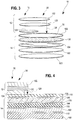
- FIGS. 3-7 provide examples of various lower laminates 14.
- the sub-tab layer is provided between the tab or upper laminate including the tab and the lower laminate and the foam in the lower laminate.
- the lower laminate 14 includes, from bottom to top, a heat seal layer 100, an optional polymer film support layer 102 above and over the seal layer 100, a membrane or an induction heatable layer 104, which is a metal layer, above the support layer.
- a membrane or an induction heatable layer 104 On top of the membrane layer 104 is an insulation layer or heat redistribution 106, which is a polymer foam layer, and a top non-foam polymer support layer 108, which is a non-foam, polymer sub tab layer.
- the lower sealant or heat seal layer 100 may be composed of any material suitable for bonding to the rim of a container, such as but not limited to induction, conduction, or direct bonding methods.
- Suitable adhesives, hot melt adhesives, or sealants for the heat sealable layer 100 include, but are not limited to, polyesters, polyolefins, ethylene vinyl acetate, ethylene-acrylic acid copolymers, Surlyn TM , and other suitable materials.
- the heat sealable layer may be a single layer or a multi-layer structure of such materials about 5 to 80 ⁇ m (about 0.2 to about 3 mils) thick.
- the heat seal layer is selected to have a composition similar to and/or include the same polymer type as the composition of the container. For instance, if the container includes polyethylene, then the heat seal layer would also contain polyethylene. If the container includes polypropylene, then the heat seal layer would also contain polypropylene. Other similar materials combinations are also possible.
- Support layer 102 is optional in the laminate 114. If included, it may be polyethylene terephthalate (PET), nylon, or other structural polymer layer and may be, in some approaches, about 12 to 25 ⁇ m (about 0.5 to about 1 mil) thick.
- PET polyethylene terephthalate
- nylon nylon
- other structural polymer layer may be, in some approaches, about 12 to 25 ⁇ m (about 0.5 to about 1 mil) thick.
- the membrane layer 104 may be one or more layers configured to provide induction heating and/or barrier characteristics to the seal 10.
- a layer configured to provide induction heating is any layer capable of generating heat upon being exposed to an induction current where eddy currents in the layer generate heat.
- the membrane layer is a metal layer, such as, aluminum foil, tin, and the like.
- the membrane layer may also include an atmospheric barrier layer capable of retarding the migration of gases and moisture at least from outside to inside a sealed container and, in some cases, also provide induction heating at the same time.
- the membrane layer may be one or more layers configured to provide such functionalities.
- the membrane layer is about 8 to 50 ⁇ m (about 0.3 to about 2 mils) of a metal foil, such as aluminum foil, which is capable of providing induction heating and to function as an atmospheric barrier.
- Layer 106 may be an insulation layer or a heat-redistribution layer.
- Layer 106 is a foamed polymer layer.
- Suitable foamed polymers include foamed polyolefin, foamed polypropylene, foamed polyethylene, and polyester foams. In some forms, these foams generally have an internal rupture strength of 787 to about 1378 g/cm ( 2000 to about 3500 g/in).
- the foamed polymer layer 106 may also have a density less than 0.6 g/cc and, in some cases, about 0.4 to less than about 0.6 g/cc. In other approaches, the density may be from about 0.4 g/cc to about 0.9 g/cc.
- the foamed polymer layer may be about 25 to 130 ⁇ m (about 1 to about 5 mils) thick.
- outer polymer support layer 108 On top of the lower laminate 14 is an outer polymer support layer 108, which may be a non-foam PET, nylon, or other structural-type polymer layer(s) such as polyolefin or copolymers thereof.
- Outer layer 108 is a non-foam, polymer sub tab layers discussed herein.
- layer 108 may be an asymmetrical polyester film having an upper layer of an amorphous polyester and a lower layer of a crystalized polyester layer.
- the amorphous polyester layer may have a lower melting point than the crystalized polyester and may aid in achieving a good bond with the upper laminate 12 and improve processing over hot rollers and other equipment during seal manufacture.
- the layer 108 is a co-extruded layer with the crystalized layer being thicker than the amorphous layer.
- the amorphous layer may form the bond with the upper laminate 12 and form the upper surface 32 of the lower laminate 14.
- the upper laminate 14 may also include other layers as needed for a particular application, which may be layers in between the various layers discussed herein as appropriate for a particular application.
- layer 108 may be one or more layers of a polyolefin.
- layer 108 may be about 25 to 130 ⁇ m (about 1 to about 5 mils) thick and have a density of about 0.9 to about 1.5 g/ml (in some cases about 0.9 to about 1.2, and in other cases, about 0.9 to about 1.0 g/ml, and in yet other cases about 0.9 to about 0.96 g/ml).
- each of the layers of FIG. 3 may also be bonded to the layer adjacent to it via an optional adhesive or tie layer 110.
- adhesive or tie layers may be the same, as shown in the exemplary seal of FIG. 4 , but may also be different in composition.
- the adhesives useful for any of the optional adhesive or tie layers described herein include, for example, ethylene vinyl acetate (EVA), polyolefins, 2-component polyurethane, ethylene acrylic acid copolymers, curable two part urethane adhesives, epoxy adhesives, ethylene methacrylate copolymers and the like bonding materials.
- EVA ethylene vinyl acetate
- 2-component polyurethane ethylene acrylic acid copolymers
- curable two part urethane adhesives epoxy adhesives
- ethylene methacrylate copolymers and the like bonding materials ethylene methacrylate copolymers and the like bonding materials.
- Other suitable materials may include low density polyethylene, ethylene-acrylic acid copolymers and ethylene methacryl
- any optional adhesive layers may be a coated polyolefin adhesive layer.
- adhesive layers may be a coating of about 5 to 13 ⁇ m (about 0.2 to about a 0.5 mil) (or less) adhesive, such coated ethylene vinyl acetate (EVA), polyolefins, 2-component polyurethane, ethylene acrylic acid copolymers, curable two part urethane adhesives, epoxy adhesives, ethylene methacrylate copolymers and the like bonding materials.
- EVA coated ethylene vinyl acetate
- the layers forming the upper laminate may extend only partially across the sealing members 10 as generally shown in FIGS. 3 and 4 .
- the layers 122 and 120 may also extend the full width and full surface area of the sealing members as generally shown in FIGS. 10 and 11 .
- Layers 122 and 120 will be explained further below in the context of FIG. 3 , but it will be appreciated that full layers of these portions will have similar characteristics and constructions.
- the laminate 12 includes a layer of heat activated adhesive or a heat activated bonding layer 120 and a corresponding or overlapping upper polymer support layer 122 where the adhesive layer 120 partially bonds 126 the support layer 122 to the upper surface 32 of the lower laminate 14 to form both the tab portion 16 and the bonded portion 30.
- the upper polymer support layer 122 may be PET, nylon, or other structural-type polymer layer(s). As noted above, layer 120 and layer 122 may also extend the full width and surface area of the seal 10.
- the upper laminate also includes a partial layer 124, which is shorter or smaller than layers 120 and 122 of the laminate 112, and called a tab stock.
- the tab stock 124 is adhered or bonded to the adhesive layer 120 on a top surface thereof, but is not bonded to the lower laminate 14 (or any sub-tab polymer layer) in the final assembly.
- the tab 16 may also be formed without a tab stock 124 and, instead, utilize a part layer of adhesive corresponding only to the bond area 30. (This optional way of forming the tab 16 may be utilized on any of the seal approaches described herein.)
- the tab 16 is defined or formed via the tab stock 124 that extends only part way across the upper laminate 12. More specifically, the tab stock 124 forms the tab 16 because it bonds to the heat-activated bonding layer 120 and generally prevents layer 122 (and any layers above) from adhering to the upper surface 32 of the sub-tab polymer layer across at least a portion thereof as generally shown in FIGS. 3 and 4 . That is, a top surface of the tab stock 124 is adhered to a lower portion of the heat-activated bonding layer 120. A bottom surface of tab stock 124 is adjacent to, but not bonded to, the upper surface of the sub-tab polymer layer to form the tab 16.
- the tab stock 124 is formed of polyester, such as polyethylene terephthalate (PET), or paper.
- PET polyethylene terephthalate
- a lower surface of the tab stock 124 may be coated with a release material, for example silicone.
- the optional release coating minimizes the possibility that the tab stock 124 will become adhered to the upper surface of the sub-tab polymer layer during the heat sealing or induction heat sealing process. However, such release coatings are not typically necessary.
- the tab stock 124 permits the tab structure 16 to pivot or hinge upwardly along a boundary line 34 to form the tab 16.
- the tab stock 124 and formed tab 16 are defined wholly within a circumference or perimeter 22 of the seal.
- the heat-activated bonding layer 120 may include any polymer materials that are heat activated or heated to achieve its bonding characteristics or application to the seal.
- the heat-activated bonding layer may have a density of about 0.9 to about 1.0 g/cc and a peak melting point of about 60 to 70°C (about 145°F to about 155°F).
- a melt index of the bonding layer 120 may be about 20 to about 30 g/10 min (ASTM D1238).
- Suitable examples include ethylene vinyl acetate (EVA), polyolefin, 2-component polyurethane, ethylene acrylic acid copolymers, curable two-part urethane adhesives, epoxy adhesives, ethylene methacrylate copolymers and the like bonding materials.
- EVA ethylene vinyl acetate
- the heat activated bonding layer 120 extends the full width of the laminate segment 12 (but not the full width or length of the entire seal 10 or the entire lower laminate 14).
- the laminate 12 may only include a partial layer of adhesive and, thus, not use the tab stock layer 124 discussed above.
- the bonding layer 120 extends the full width of the seal and is partially bonded to the lower laminate portion and partially bonded to the tab stock 124. In yet other approaches, the bonding layer 120 is partially bonded to the polymer support layer 108.
- the heat-activated bonding layer 120 is EVA with a vinyl acetate content of about 20 to about 28 percent with the remaining monomer being ethylene in order to achieve the bond strengths to securely hold the upper laminate to the lower laminate.
- a vinyl acetate content lower than 20 percent is insufficient to form the robust structures described herein.
- bonding layer 120 may be about 12 to 90 ⁇ m (about 0.5 to about 3.5 mil) of EVA, in other approaches about 12 to 65 ⁇ m (about 0.5 to about 2.5 mils) of EVA, in other approaches, about 12 to 40 ⁇ m (about 0.5 to about 1.5 mils) of EVA and, in yet other approaches, about 12 to 25 ⁇ m (about 0.5 to about 1.0 mils) of EVA; however, the thickness can vary as needed for a particular application to achieve the desired bonds and internal strength.
- sealing members including a tab defined wholly within a perimeter of the sealing member
- the stress upon tab pulling radiates downwardly and away from this hinge joint into the layers below the tab and, in some cases, results in a tearing of the layer immediately below the tab. This failure tends to occur more often in prior tabbed sealing members when the layer immediately below the tab is a foamed polymer.
- the structural support layer 108 is also advantageous because it provides a more rigid, non-foam layer underneath the focal point of the tab pulling stress to provide a more robust laminate structure upon tab pulling.
- the pulling stresses are dissipated throughout a denser, more rigid layer providing a more robust tab capable of withstanding even stronger heat seal bonds to containers.
- the density of the non-foam polymer layer under the tab in some approaches, may be about 0.9 to about 1.2 g/cc.
- the sub-tab layer may also be about 25 to 130 ⁇ m (about 1 to about 5 mils) thick.
- FIGS. 5 and 6 show a disclosed approach of a sealing member 101 described herein.
- a lower laminate 114 includes just a lower sealant or heat seal layer 100 combined with a membrane layer 104 bonded together with an optional adhesive layer 110.
- the upper laminate 12 or segment may also include similar layers as the version discussed above.
- the segment 12 may include an upper polymer support 122, a heat activated bonding layer 120, and the tab stock 124.
- the composition of these layers is similar to the version discussion above and will not be discussed further.
- the lower laminate may be from about 25 to 130 ⁇ m (about 1 to about 5 mils) thick, and in other approaches, about 25 to 80 ⁇ m (about 1 to about 3 mils) thick.
- FIGS. 5 and 6 The approach of FIGS. 5 and 6 is advantageous because it presents an exposed membrane layer (often a foil layer) as a portion of, and in some cases, the majority of the top surface of the sealing member 101. Additionally, in view of the relatively thin laminate 114, the sealing member 101 can be opened by either a consumer pulling on the tab 16 to peel the sealing member from the container rim or, alternatively, exposed portions 200 of the seal (that is, the portions of the seal not covered by the upper laminate segment 12) can easily be punched through or pierced by a consumer. This enables push/pull functionality to the seal—that is, push or pierce through the lower laminate 14 and pulling of the tab 16 to peel the seal 10 from the container.
- FIG. 7 shows an approach with the tab stock 124 formed from a PET layer
- FIG. 8 shows an alternative approach with the tab stock 124 formed from a paper layer; however, the tab stocks of these figures may also be interchangeable.
- FIG. 7 illustrates the seal of FIGS. 5 or 6 in a disclosed two-piece seal and liner assembly 300.
- the other seals described herein may also be used in a similar arrangement.
- a top surface of the sealing member 101 is temporarily bonded to a liner 302 shown as an optional pulp backing in FIG. 7 .
- the liner 302 is temporarily adhered to seal 101 via an intermediate layer 304, which in this approach, is a heat-activated layer of wax or microcrystalline wax.
- the wax layer 304 bonds the liner 302 to the seal 101.
- heat in some approaches, induction heating from the metal layer
- induction heating from the metal layer flows upwardly in the seal and activates or melts the wax 304 to release the bond between the liner 302 and the sealing member 101, which separates the two components.
- the wax is melted and absorbed by the liner 302.
- Other releasable layers that provide a temporary bond between layer 104 and 302 may also be used.
- the seal of FIG. 7 eliminates the additional tab forming layers at the center and central portions of the seal 101 so that these areas with the weakest eddy currents in induction sealing do not need to generate high levels of heat to flow through additional layers of material in order to reach and melt the center wax areas.
- the seal of FIG. 7 provides and improved two-piece seal and liner assembly even with a tab defined wholly within a perimeter or circumference of the seal.
- the upper laminate 12 can be thicker than normally used in tabbed seals and, in some approaches, be greater than about 120 ⁇ m (about 5 mils), and in other approaches be about 120 to 250 ⁇ m (about 5 to about 10 mils) thick.
- This layer can also include other structural support layers without the problem of hindering upwardly directed heat flow.
- laminate 12 may include thick polymer and/or thick foam layers to improve tab rigidity.
- the liner 302 can be formed of one or more layers of cardboard, pulp board, or a synthetic compressing agent (such as a synthetic foam or synthetic fibers) that is effective for absorbing the release layer 304, such as wax, upon being activated by heating.
- the liner 302 may include a layer of foamed plastic material to which a paper layer (not shown) has been adhered to a bottom surface thereof.
- the paper layer is the layer in contact with the release layer 304 for absorbing the molten wax or other activated components thereof.
- the liner 302 may have a thickness in the range from about 400 to about 1800 microns.
- Synthetic foam or fibers may also be useful as materials or the liner if they are formed into a layer with a suitable compression factor comparable to pulp board of the type traditionally used in induction seals.
- LDPE low density polyethylene
- PP polypropylene
- PS polystyrene foam or fibers
- the synthetic material selected should have a sufficient absorbency, suitable pore volume, and structure to absorb substantially all of the wax used in the seal. The dimensions of the compressing agent absorbing material will vary according to the application and the size of the opening of the container and size and construction of the closure being used.
- the release layer 304 may be a wax layer.
- the wax may include any suitable wax material which will melt within the temperature range to which the sealing member is to be subjected by an energy source during the induction sealing process.
- the wax layer may include paraffin, microcrystalline waxes, and blends thereof.
- the wax layer may comprise a blend of paraffin wax and microcrystalline wax wherein the proportion of microcrystalline wax used in the wax layer is adjusted to provide the wax layer being formulated to enhance the ability of the wax to be absorbed by the liner.
- the wax layer may include microcrystalline wax modified with other polymeric additives to enhance its initial bonding properties.
- the wax layer may comprise microcrystalline wax modified with at least one of ethylene vinyl acetate and polyisobutylene.
- the application of induction energy to the sealing member heats the membrane layer 104 to a temperature, in some approaches, from about 150 to 230°C (about 300 to about 450°F).
- the volume or thickness of the wax layer therefore, should be selected such that substantially all of the wax will melt during the manufacturing process and be absorbed by the compressing agent.
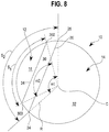
- FIGS. 8 and 9 schematically show some of the relative features of the seal when viewed from above and the unique characteristics of the circular segment upper laminate 12.
- the total upper laminate segment portion 12 may be defined by an angle ⁇ 1 between radius lines extending from the center C to the chord endpoints 24 and 26 of about 125° to about 150°, in other approaches, about 130 to about 140°, and in yet other approaches, about 130 to about 138°.
- the upper surface of the seals herein are formed from a minor portion of the top layer from the upper laminate portion 12 and by a major portion from the top layer of the lower seal laminate 14.
- the tab 16 of the upper laminate circular segment may also define a second circular segment and may be defined by a second angle ⁇ 2 between radius lines extending outwardly from the center C to secondary chord endpoints 300 and 302 on opposite sides of a chord defining the pivot line 34 of about 90 to about 120°, in other approaches, about 100 to about 115°, and in yet other approaches, about 105 to about 112°.
- the seals define a tab 16 that wholly defined within a perimeter of the seal in a ratio of tab surface area to the surface area of the bond area 30 of about 1:1 to about 3:1 and in some approaches, about 1:1 to about 2:1. These ratios are achieved even when the upper laminate portion 12 is less than about 50 percent of the seal, in some approaches, less than about 40 percent of the seal, and in yet other approaches, less than about 35 percent of the seal's upper surface area.
- FIG. 9 another schematic of a sealing member is shown showing various relative relationships between the upper laminate circular segment portion 12 and the upper surface 32 of the lower laminate 14 effective for the sealing member to function as an overlapping tab on several different configurations of lower laminate.
- the upper laminate circular segment 12 has a total height H that is about 15 to about 40 percent (in some approaches, about 20 to about 30 percent) of the total length of the sealing member with the total length of the exposed lower laminate portion 32 being about 60 to about 85 percent (in other approaches, about 70 to about 80 percent) of the total sealing member length.
- a ratio of the circular segment height to the length of the exposed lower laminate 32 may be about 0.2 to about 0.7.
- FIG. 10 one example of a sealing member 200 including a sub tab layer 202 is disclosed.
- the sub tab layer 202 is bonded to the lower laminate 214 and, in particular, to the upper surface 32 and in the approach of FIG. 10 , the foil layer 104 of the lower laminate 214.
- sub tab layer 202 may be bonded to a foam layer above the foil layer 104.
- the sub tab 202 is not bonded to the tab 16 or the upper laminate 212. While the sub tab layer 202 is shown bonded to a particular lower laminate, the structure of the lower laminate is not particular limited and can be any single or multi-layer film structure, such as the other lower laminates discussed herein.
- the sub tab 202 may be a paper layer adhered to the lower laminate via a hot melt adhesive or a film layer (polyolefin, polyester, nylon, etc.) heat bonded or adhered to the lower laminate via a thin coating of adhesive.
- the sub tab 202 may be about 25 to 130 ⁇ m (about 1 to about 5 mils) thick and, in other disclosures, about 25 to 50 ⁇ m (about 1 to about 2 mils) thick.
- the sub tab layer may be coextensive with the tab stock 124, which may also be a paper layer so that this disclosure presents a paper to paper interface between the tab 16 of the upper laminate 12 and the lower laminate 214.
- the sub tab may also extend the entire width and surface area of the seal (not shown) as needed for a particular application as discussed previously and as discussed more below.
- the sub tab layer 202 provides structural support and aids in minimizing the formation of folds, creases, wrinkles and other deformities when the tab layer is applied to the lower laminate.
- the sub tab layer 202 may be particularly advantageous in providing structural support for lower laminates that are 80 ⁇ m (3 mils) or less as these are the most prone to such structural defects during handling and cap sealing and, in some cases, when combined with a gripping tab.
- the sub tab layer 202 may aid in providing the concentric structural stability discussed previously during a cap heat scaling process.
- the sealing member 200 may also include optional upper layers 220 above the tabbed seal.
- the upper layers may provide additional structural support and may include a paper or cellulose backing layer 222 and an adhesive layer 224.
- the paper backing layer 222 may be about 120 to 250 ⁇ m (about 5 to about 10 mils) of paper backing.
- Adhesive layer 224 may be any of the exemplary adhesive layers discussed above. This disclosure provides a robust tab 16 but still provides easy access to the container contents by, for instance, piercing or punching through the foil layer via the portions of the seal 200 not covered by the upper laminate 12.
- FIG. 11 provides yet another example of a sealing member 300 utilizing the sub tab layer 202 combined with a lower laminate 214, which in this disclosure is similar to that described above with FIG. 10 .
- the lower laminate 214 may be any single or multi-layer laminate as needed for a particular application, such as any of the lower laminates discussed previously.
- a tab 215 is formed from a polymer layer 350, which may be a structural polymer layer such as polyester (PET), PEN, nylon, or the like. Above the layer 350 may be an additional support layer, such as backing layer 222 (which may be bonded to layer 350 via adhesive layer 224, which is not shown in FIG. 11 ).
- the tab is formed via a partial bond or adhesive layer, which does not extend the full length of the seal 300, of a composite adhesive film or laminate 352 formed from a polyester core layer 354 sandwiched between two outer layers of a heat bondable materials 356 and 358.
- Composite film layer 352 may be about 50 to 200 ⁇ m (about 2 to 8 mils) thick, and in some disclosures, about 70 to 100 ⁇ m (about 3 to about 4 mils) thick.
- the heat bondable materials 356 and 358 may include any polymer materials that are heat activated or heat applied to achieve its bonding characteristics.
- the heat-bondable layer may have a density of about 0.9 to about 1.0 g/cc and a peak melting point of about 60 to 70° C (about 145°F to about 155°F).
- a melt index of the heat bondable material may be about 20 to about 30 g/10 min (ASTM D1238).
- Suitable examples include ethylene vinyl acetate (EVA), polyolefin, 2-component polyurethane, ethylene acrylic acid copolymers, curable two-part urethane adhesives, epoxy adhesives, ethylene methacrylate copolymers and the like bonding materials.
- the heat bondable material is EVA with a vinyl acetate content of about 20 to about 28 percent with the remaining monomer being ethylene in order to achieve the bond strengths in order to securely hold the upper laminate to the lower laminate.
- a vinyl acetate content lower than 20 percent is insufficient to form the robust structures described herein.
- layer 352 may include upper and lower layer 356 and 358 about 12 to 40 ⁇ m (about 0.5 to about 1.5 mil) of EVA and, in other disclosures, about 12 to 25 ⁇ m (about 0.5 to about 1.0 mils) of EVA; however, the thickness can vary as needed for a particular application to achieve the desired bonds and internal strength.
- Sealing member 300 may also include the sub tab layer 202 discussed above to provide structural support to the layers above and below the tab.
- the sub tab layer 202 in this disclosure, may have similar characteristics as the sub tab layer discussed above.
- the layer 202 is bonded to the upper surface of the lower laminate and not bonded to the layer(s) 350 forming the tab 215.
- the sub tab layer 202 may, instead of being coextensive with the primary tab 16 or any tab stock 124 thereof, extend laterally beyond the boundaries of the tab 16 or tab stock 124.
- the sub tab layer could be coextensive with the upper laminate or extend over half of the sealing member.
- a tabbed sealing member for sealing to a rim of a container
- the tabbed sealing member includes an overlapping upper laminate that may include a lower seal portion having a top surface with a total surface area and including a heat sealable layer configured for heat sealing to a container rim, an upper laminate at least partially bonded to the top surface of the lower seal portion to form a gripping tab defined wholly within a perimeter of the lower seal portion.
- the upper laminate has a top surface with a surface area less than the total surface area of the lower seal portion top surface and forming a circular segment defined by an edge forming a chord extending across the lower seal portion and spaced from a center of the tabbed sealing member.
- the sealing member includes a sub tab layer coextensive with at least the gripping tab or extending the full extent of the seal.
- the sub tab layer is bonded to the top surface of the lower seal portion and not bonded to the gripping tab.
- the sub tab layer may be paper, polymers, polyester, and the like materials.
- a full backing layer is adhered to both the top surface of the upper laminate and the top surface of the lower seal portion.
- the backing layer is paper about 120 to 250 ⁇ m (about 5 to about 10 mils) thick.
- the tabbed sealing member may also include wherein an upper laminate with a heat activated bonding layer forming the at least partial bond to the top surface of the lower seal portion or a tab stock bonded to the heat activated bonding layer but not bonded to the top surface of the lower seal portion to form the gripping tab.
- an upper surface of the tabbed sealing member may be partially defined by a minor portion of the top surface of the upper laminate and a major portion of the top surface of the lower seal portion.
- the upper surface of the tabbed sealing member may also be temporarily bonded to a liner with portions of the liner are temporarily bonded to the top surface of the upper laminate and other portions of the liner are temporarily bonded to the top surface of the lower seal portion.
- the lower seal portion may have a thickness and composition configured to be pierced through portions of the tabbed sealing member not covered by the upper laminate.
- the circular segment forming the upper laminate may be defined by a sweep angle of the formula 2arccos (H1/radius). In some approaches, this angle may be about 125 to about 150°. In other approaches, the tab of the upper laminate is a circular segment being less than a semicircle and defined by a second sweep angle of the formula 2arccos (H2/radius). In some approaches, this angle may be about 90 to about 120°.
- the circular segment of the upper laminate in some forms, may cover about 10 to about 40 percent of the upper surface of the tabbed sealing member with the remainder of the upper surface being the top surface of the lower seal portion.
- the lower seal portion includes a metal foil.
- the lower seal portion also includes a foamed polymer.
- a tabbed sealing member for sealing to a rim of a container includes a lower seal portion having a top surface with a total surface area and including a heat sealable layer configured for heat sealing to a container rim.
- the seal further includes an upper laminate partially bonded to the top surface of the lower seal portion to form a gripping tab defined wholly within a perimeter of the lower seal portion.
- the partial bond is formed by a composite layer of a polyester sandwiched between heat bondable materials on opposite sides of the polyester.
- the seal also includes a sub tab layer coextensive with the gripping tab. The sub tab layer is bonded to the top surface of the lower seal portion, but not bonded to the gripping tab.
- the upper laminate includes a layer of polyester and a paper backing layer.
- the tabbed sealing members herein may include multicomponent segmentation with a separate layer segmented from and adjacent to the upper laminate forming the tab. That is, the upper laminate may be adjacent to and separate from another segmented layer also bonded to the lower seal portion but distinct from the upper laminates discussed above.
- the segmented layer may be a single or multi-layer laminate that is the same thickness as the upper laminate forming the tab in the various approaches above.
- the segmented layer may be a paper layer.
- seals may include other layers within the laminate and between the various layers shown and described as needed for a particular application. Adhesive layers not shown in the Figures may also be used, if needed, to secure various layers together. Unless otherwise stated herein, all parts and percentages are by weight.
Description
- The disclosure relates to a pull-tab sealing member for closing the mouth of a container, and more particularly, to a pull-tab sealing member having a tab formed with a sub tab layer underneath to provide concentric stability between peripheral portions of the sealing member and central portions of the sealing member during heat sealing to a container rim.
- It is often desirable to seal the opening of a container using a removable or peelable seal, sealing member, or inner seal. Often a cap or other closure is then screwed or placed over the container opening capturing the sealing member therein. In use, a consumer typically removes the cap or other closure to gain access to the sealing member and then removes or otherwise peels the seal from the container in order to dispense or gain access to its contents.
- Initial attempts at sealing a container opening utilized an induction- or conduction-type inner seal covering the container's opening where the seal generally conformed to the shape of the opening such that a circular container opening was sealed with a round disk approximately the same size as the opening. These prior seals commonly had a lower heat activated sealing layer to secure a periphery of the seal to a rim or other upper surface surrounding the container's opening. Upon exposing the seal to heat, the lower layer bonded to the container's rim. In many cases, these seals included a foil layer capable of forming induction heat to activate the lower heat seal layer. These prior seals tended to provide good sealing, but were often difficult for a consumer to remove because there was nothing for the consumer to grab onto in order to remove the seal. Often, the consumer needed to pick at the seal's edge with a fingernail because there was little or no seal material to grasp.
- Other types of seals for containers include a side tab or other flange that extended outwardly from a peripheral edge of the seal. These side tabs are generally not secured to the container rim and provide a grasping surface for a consumer to hold and peel off the seal. These side tabs, however, extend over the side of the container rim and often protrude into a threaded portion of the closure. If the side tab is too large, this configuration may negatively affect the ability of the seal to form a good heat seal. The side tabs (and often the seal itself) can be deformed or wrinkled when the closure or other cap is placed on the container due to contact between the closure (and threads thereof) and tabbed part of the seal. To minimize these concerns, the side tabs are often very small; thus, providing little surface area or material for a consumer to grasp in order to remove the seal.
- Yet other types of seals include a sealing member having a tab defined on the top of the seal. One approach of these prior seals includes a partial layer of coated pressure sensitive adhesive to secure the tab to a layer of metal foil. The tab was formed by a full layer extending across the entire surface of the sealing member, but the full layer was only bonded to half of the seal to form the tab. This type of top-tabbed seal offered the advantage of a larger tab, which provided more grasping area for the consumer to hold and peel off the seal, but required a full additional layer of material in order to form the tab. In other approaches, the seal may include a tab formed from the additional full layer of film combined with an additional full layer of adhesive utilizing a part paper or part polymer layer, called a tab stock, to form the tab. This part layer is inserted between the additional full layer of adhesive and lower seal portions to prevent the tab from sticking to the layers below, which formed the tab. In all the prior types of top-tabbed-like seals, the gripping tab was formed by a full layer of material (or a full layer of material and a full layer of adhesive) that extended across the entire surface of the seal.
- As mentioned above, a cap or other closure is typically screwed or otherwise secured to a finish or neck of a container. This captures the sealing member between the top of the cap and container rim. In many instances, the cap has an annular bead or downwardly protruding ring (sometimes called a bead line) on the underside of its top inner surface. This annular bead is sized and positioned to generally correspond with an upper land area of the container rim when the cap is secured to the container. This annular bead helps provide pressure to secure the sealing member to the rim land area. However, many of the prior sealing members included a foam layer to provide insulation from heat generated during the heat sealing process.
EP 1837288 A1 shows an example of a sealing member for sealing to a rim surrounding a container opening, the sealing member comprising a multi-layer laminate including an upper laminate portion partially bonded to a lower laminate portion and forming a gripping tab defined wholly within a perimeter of the sealing member, the gripping tab for removing the sealing member from the container opening, the lower laminate portion including at least a heat seal layer for bonding to the container rim, a metal layer above the heat seal layer for heating the heat seal layer, and a polymer foam layer above the metal layer. In some cases, there can be problems with the foam layer interacting with the cap annular bead during the cap sealing process. Heat from the cap sealing process combined with the focused downward pressure from the annular bead on the foam layer in the sealing member can damage or result in deterioration of the foam layer in the areas above the container rim. In extreme cases, the foam may melt or air cells in the foam may collapse. This shortcoming is more prevalent when the cap sealing process is over sealed (that it, when too much heat is applied or heat is applied for too long during the cap sealing process). - This melting and/or cell collapse may result in exposure of the metal foil or other polymer layers below the foam at the peripheral areas of the sealing member. In some cases, when the consumer lifts up the tab to remove the sealing member, the consumer is presented with an unsightly seal having an uneven foam layer under the tab with intact center portions of foam and melted or damaged edge portions of the foam. In extreme cases, the outer peripheral portions of the foam may melt completely, which exposes the metal foil or other layers under the tab.
-
-
FIG. 1 is a perspective view of a disclosed tabbed sealing member; -
FIG. 2 is a cross-sectional view of another disclosed sealing member; -
FIG. 3 is an exploded perspective view of an exemplary sealing member according to the invention; -
FIG. 4 is a cross-sectional view of another exemplary sealing member; -
FIG. 5 is an exploded perspective view of another disclosed sealing member; -
FIG. 6 is a cross-sectional view of another disclosed sealing member; -
FIG. 7 is a cross-sectional view of another disclosed sealing member temporarily bonded to a liner via a wax or other release layer; -
FIGS. 8 and9 are top plan views of exemplary tabbed sealing members; -
FIG. 10 is a cross-sectional view of another disclosed tabbed sealing member; and -
FIG. 11 is a cross-sectional view of another disclosed tabbed sealing member.Figures 1, 2 and5 to 11 do not depict all the features of the invention, but show further possible features of a tabbed sealing member. - The invention is defined in the appended claims. When confronted with a heat management problem during a cap sealing process, such as the one set forth in the background, the conventional approach would be to add more insulation. In the case of tabbed sealing members with a foam layer, additional insulation may be obtained by adding further foamed polymers or by increasing the thickness of any existing foamed polymer layers. It is well understood that foaming of a polymer layer decreases its thermal conductivity and, thus, increases the ability of the foamed polymer to provide insulation and hinder the transfer of heat. Thicker foams would also logically compensate for the added pressure due to the cap's annular bead. Thus, the logical approach to solve the deteriorating foam issues of prior sealing members would have been to include a thicker foam layer or include additional foam layers to provide more insulation to hinder the flow of heat and/or to better absorb the downward pressure from the cap's annular bead.
- The tabbed sealing members of the present application, however, take the unconventional approach of including one or more non-foamed, polymer layers between a tab and a foamed polymer layer in a seal laminate to provide a more robust tabbed sealing member. The sealing members of the present application are unexpectedly better able to withstand additional or excessive heating during the cap sealing process when combined with a cap or closure including the annular bead on its inner surface. The approach of the present application is unconventional because the non-foamed, polymer layer(s) have a higher thermal conductivity and are more rigid (as compared to foam) and would be expected to conduct more heat and not absorb the downward pressure of the cap as well as foam during the cap sealing process.
- It was unexpectedly discovered that including one or more of these non-foamed, polymer layers between the tab and the foam actually helped reduce foam damage due to melting and cell collapse at the outer peripheral edge when the tabbed sealing members are exposed to excessive heating and the cap's annular bead during a cap sealing process. In some approaches, the non-foam, polymer layer(s) are positioned in the laminate between the tab and foam layers to be at least co-extensive with a peripheral edge of the tab and to extend inwardly along with the tab only part way across the seal. In other approaches, the non-foam, polymer layers(s) may also extend over the entire seal structure. In this manner, the non-foam, polymer layer(s) provides improved concentric stability to the sealing member and to the foamed polymer layer under the tab during cap sealing process. Concentric stability is the ability of the tabbed sealing member to generally maintain the integrity and cell structure of the foamed polymer layer at its peripheral edge above the container rim land area generally consistent with the integrity and cell structure of the foam layer at radially inner portions away from the edge. This concentric stability is achieved via the unconventional approach of using a thermally conductive and more rigid non-foam polymer rather than the conventional approach of using additional or thicker foamed insulation layers to address issues with the flow of heat and added pressure of the cap's annular bead during cap sealing.
- This disclosure provides a concentrically stable tabbed sealing member with a foam layer therein for sealing to a rim surrounding a container opening. The concentrically stable tabbed sealing member includes a multi-layer laminate with an upper laminate portion partially bonded to a lower laminate portion forming a gripping tab defined wholly within a perimeter of the sealing member. The gripping tab is arranged and configured for removing the sealing member from a container opening. The lower laminate portion below the gripping tab (such as when viewed through a cross-section extending through the tab) includes at least a seal layer for bonding to the container rim, a metal layer for heating the seal layer, and a polymer foam layer above the metal layer. Other layers may be included as needed.
- The tabbed sealing members of the invention (when viewed, for instance, through a cross-section extending through the tab), include one or more non-foam, polymer sub-tab layers between the polymer foam layer and the gripping tab. The non-foam, polymer sub-tab layer may be bonded to the upper surface of the lower laminate which may be a foam layer. The one or more non-foam, polymer sub-tab layers are coextensive with at least the gripping tab at a periphery thereof. For instance, the one or more non-foam, polymer sub-tab layers may be partial layers coextensive with the tab or, as discussed more below, coextensive with a so-called tab stock layer. In other approaches, the one or more non-foam, polymer sub-tab layers may also extend over the entire sealing member between the upper laminate portion and polymer foam layer of the lower laminate portion. Even though the sub-tab layer is a non-foam polymer and tends to conduct more heat than a foamed polymer, it provides concentric structural support to the polymer foam layer at its periphery thereof relative to portions of the polymer foam layer radially inward from the periphery when exposed to heating and the cap's annular bead during a cap sealing process.
- This disclosure also includes a container and cap assembly that includes the concentrically stable tabbed sealing member with foam mentioned above. The container includes a rim surrounding an opening thereof, and the cap closes the opening of the container. The cap includes a downwardly extending annular bead on a top inner surface thereof. The annular bead is arranged and configured to generally align with a land area of the container rim when the cap is received on a neck or other finish of the container.
- In yet another disclosure, a pull-tab sealing member for a container is described herein containing an upper laminate forming a pull-tab bonded to a lower laminate capable of being heat sealed to a container's mouth or opening. The upper laminate defines a pull tab wholly within a perimeter or circumference of the seal. The sealing member includes a sub tab polymer layer underneath the tab and bonded to the lower laminate, but not bonded to the tab itself. This sub tab layer adds structural support to stabilize the sealing member and tab to aid in minimizing folding, wrinkles, creases, and the like. The sub tab polymer layer can be coextensive with the tab, extend slightly beyond the tab, but not extend the full width of the sealing member, or the sub-tab polymer layer may extend the full surface area of the sealing member. For instance, the sub tab polymer layer may be coextensive with a tab stock, be coextensive with the full upper laminate, or may be other sizes as needed for a particular application. This sub tab polymer layer can, in some approaches, be particularly advantageous in seals with relatively thin lower laminates (such as about 80 µm (about 3 mils) or less), but can be used in a wide variety of seals needing structural support with a tab. The sub tab layer may aid in providing concentric stability of the sealing member.
- In other aspects of this disclosure, the upper laminate of the seal does not extend the full width of the sealing member in order to define the gripping tab. To this end, the pull-tab sealing members herein may also combine the advantages of a tabbed sealing member with a large gripping tab defined completely within the perimeter of the seal, but achieve such functionality with less material (in view of the part layers of the upper laminate) and permit such a tab structure to be formed on many different types of preformed lower laminates. This partial upper laminate shall be combined with the sub tab layer described above and/or additional upper layers (such as a full paper layer) as needed for particular applications. The partial upper laminate structure is advantageous, in some approaches, for use with a seal configured for large or wide mouth containers, such as containers with an opening from about 30 to about 100 mm (in other approaches, about 60 to about 100mm). These seals may also be used with 38 mm or 83 mm container openings, or can be used with any sized container.
- In yet another aspect of this disclosure, the tab may be formed by a full layer or partial layer of material combined with a partial width composite adhesive structure that includes a polyester core with upper and lower adhesives on opposite sides thereof. This partial composite adhesive structure bonds the upper laminate to the lower laminate to form the gripping tab. The partial composite adhesive structure shall also be combined with the above mentioned sub tab layers. The sub tab is adhered to the lower laminate and not adhered to the upper laminate to enhance structural support.
- In further aspects of this disclosure, the sealing members herein may include a pull or grip tab defined in the upper laminate portion wholly within a perimeter or circumference of the sealing member wherein an upper surface of the sealing member is partially defined by the upper laminate portion and partially defined by the lower laminate portion. In one approach of this aspect, the top surface of the sealing member is provided by a minor portion of the upper laminate and a major portion of the lower laminate. In other approaches of this aspect, the lower laminate is partially exposed at a top surface of the seal with about 50 percent to about 75 percent (or more) of the lower laminate exposed at the top surface of the entire seal. The seals of this aspect allow consumers to remove the sealing member using the tab (as in a conventional pull-tab seal) and/or puncture the sealing member by piercing the exposed lower laminate portion to provide push/pull functionality depending on the preference of the consumer. Prior tabbed seals having a top-defined gripping tab via a full width film layer generally did not allow the functionality of easy piercing because the additional full layers used to form the tab rendered the seal too difficult to pierce.
- In such aspects, the seals of the present disclosure defining a tab wholly within a perimeter or circumference of the seal (but formed by a partial layer) also provide an improved ability for the tabbed sealing member to function in a two-piece seal and liner combination. In a two-piece seal and liner combination, the tabbed sealing member is temporarily adhered across its top surface to a liner. After container opening and removal of a cap or closure, the sealing member stays adhered to the container mouth and the liner separates and remains in the container's cap.
- In some prior versions of two-piece seal and linear assemblies, the bottom layer of the sealing member is a heat seal layer that is activated by heating, such as by induction or conduction heating, in order to adhere or bond an outer periphery of the sealing member to a rim surrounding the mouth of a container. In the two-piece seal and liner combination, an upper surface of the sealing member is temporarily adhered to a lower surface of the liner by a release layer, which is often a heat-activated release layer, such as an intervening wax layer. During heating to bond the sealing member to the container, heat not only activates the lower heat seal layer, but also travels upwardly through the seal to melt the intervening wax across the entire surface of the sealing member to separate the liner from the sealing member. Often, the melted wax is absorbed by the liner in order to permit easy liner separation from the sealing member. As can be appreciated, for this sealing member and liner combination to function properly, the intervening wax layer needs to be melted across the entire surface of the sealing member. If the wax is not melted evenly all the way across the sealing member upper surface, the liner may not properly separate from the lower seal portion.
- As the prior tabbed seals required additional full layers of material (film and adhesive) to form the tab, these additional layers would tend to negatively affect heat transfer upwardly through the seal. This shortcoming of less upward heat transfer limits the ability of top-tabbed-type seals to be used in the two-component liner and seal assembly because the required additional full layers of material (film and adhesive) to form the tab often led to issues with the proper melting the wax for liner separation.
- These shortcomings of prior tabbed seals in the context of a two-piece liner and seal combinations tended to be even more pronounced in view of further shortcomings of some induction heating equipment. In an induction seal, a metal foil is often included in the seal to generate heat for activation of the heat seal. This heat is generated due to the induction apparatus forming eddy currents in the foil layer. The induction heat from the foil melts the lower heat seal layer for bonding to the container rim. In a common two-piece assembly, the induction heating generated by the foil layer is also used to melt the intervening wax layer (as mentioned above); however, the induction heating generated by the foil layer at the center of the seal is often lower than the induction heating generated by the foil at the periphery of the seal laminate. The center of the laminate is farthest away from the induction coil in the induction heating apparatus and the eddy currents in the foil are weakest at the center of the disk, which can form a cold spot in the center of the seal. This shortcoming tends to be further exaggerated in wide seals (such as those about 60 mm in diameter or larger or seals about 60 to about 100 mm across) because the center is much farther from the induction coil. Normally, such variation in induction heating between the edges of the seal laminate and the center is generally not an issue because heat is needed most at the seal's periphery for bonding to the container rim at the periphery of the seal laminates. In prior two-piece seals without top-oriented tabs, there was less material to hinder the upwardly directed flow of heat. However, when attempting to use the top-type-tabbed seals in a two-piece liner and seal combination, the extra full layers forming the tab often created problems when attempting to use induction heat to melt the intervening wax layer, especially in the center of the seal where the induction heating was the lowest.
- In further approaches of this disclosure, the tab is formed wholly within a perimeter of the sealing member, but the upper laminate and layers forming that tab are spaced from central portions and regions of the sealing member. In some approaches, the layers defining the tab in the upper laminate are provided by a circular segment that is less than a semicircle within the sealing member's upper surface. As discussed more below, in some approaches, the upper laminate circular segment forming the tab is defined by a chord (that does not extend through the center of the sealing member) and the perimeter of the sealing member along its circumference between opposing endpoints of the chord. In this manner, the lower laminate is exposed at the center and center portions of the seal so that the center portions are free of the layers forming the tab (and upper laminate). This is advantageous in a two-piece assembly because it permits greater upwardly directed heat flow in the center portions of the seal to melt the intervening wax layer more easily than the prior tabbed seals.
- Turning to more of the specifics,
FIGS. 1 and 2 generally show atabbed seal 10 having anupper laminate 12 and alower laminate 14. Theupper laminate 12 defines agrip tab 16 wholly within a circumference orperimeter 18 of theseal 10. By one approach, theupper laminate 12 is formed by one or more layers of adhesive and/or film where all layers forming theupper laminate 12 and the definedgrip tab 16 extend only partway across an upper or major surface of thelower laminate 14. In this form, theupper laminate 12 forms a circular segment defined by edges of theupper laminate 12 where oneedge 20 is a chord of theseal 10 and anotheredge 22 is a segment extending along the perimeter orcircumference 18 between opposingchord endpoints circular segment 12 is spaced adistance 28 from the center C of theseal 10. In this manner, the center portions or regions of theseal 10 are free of theupper laminate 12. In such approach, anupper surface 32 of thelower laminate 14 is exposed at a top surface of the seal, and in some cases, is exposed for at least about 50 percent and, in some cases, greater than half of the sealingmember 10. In other approaches, theupper surface 32 of thelower laminate 14 is exposed for about 50 to about 75 percent of the sealing member's upper total surface area. Theupper laminate 12 defining the gripping tab may also extend the full width and full surface area of theseal 10 as needed for particular applications. - For simplicity, this disclosure generally may refer to a container or bottle, but the sealing members herein may be applied to any type of container, bottle, package or other apparatus having a rim or mouth surrounding an access opening to an internal cavity. In this disclosure, reference to upper and lower surfaces and layers of the components of the sealing member refers to an orientation of the components as generally depicted in figures and when the sealing member is in use with a container in an upright position and having an opening at the top of the container. Different approaches to the sealing member will first be generally described, and then more specifics of the various constructions and materials will be explained thereafter. It will be appreciated that the sealing members described herein, in some cases, function in both a one-piece or two-piece sealing member configuration. A one-piece sealing member generally includes just the sealing member bonded to a container rim. A cap or closure may be also used therewith. A two-piece sealing member includes the sealing member temporarily bonded to a liner. In this construction, the sealing member is bonded to a container's rim, and the liner is configured to separate from the sealing member during heating to be retained in a cap or other closure used on the container. In a two-piece construction, a wax layer, for example, may be used to temporarily bond the sealing member to a liner. Other types of releasable layers may also be used to provide a temporary bond between the seal and liner, but the releasable layers are generally heat activated.
- In this first approach, the circular segment forming the
upper laminate 12 includes thetab portion 16, which is free to pivot upwardly at apivot line 34 because thetab 16 is not adhered to thelower laminate 14. The circular segment forming theupper laminate 12 also includes an adheredportion 30 that is directly bonded to thelower laminate 14 or any intervening layers between the upper and lower laminates. The adheredportion 30 extends between thepivot line 34 andsegment chord 20. In some approaches (turning toFIG. 9 for a moment), the adheredportion 30 of the upperlaminate circular segment 12 may have a length or height H1 that is about 30 to about 75 percent of the total length or height H of the upper laminatecircular segment laminate 12 and, in other approaches, about 40 to about 60 percent of the laminate 12, and in yet other approaches, about 30 to about 40 percent of the laminate 12 and still provides a strong bond so that thetab 16 may be used to pull the sealingmember 10 from a container rim in one piece. Thetab 16 of the upperlaminate circular segment 12 has a height or length H2 being the remainder of the upperlaminate circular segment 12, and in some cases thetab 16 is the majority of thesegment 12. In another approach, thecircular segment 12 may define a ratio oftab 16 to adheredportion 30 of about 1:1 to about 2.5:1 and, in other approaches, may be about 1.1 to about 2.1:1. - The
lower laminate 14 may be from about 25 to 500 µm (about 1 mil to about 20 mils) thick, and in some approaches, about 180 to 250 µm (about 7 to about 10 mils) thick. The lower laminate includes a lower heat seal layer for bonding to a container rim, a metal layer for heating the heat seal layer, and a polymer foam layer above the metal layer. In some approaches, however, particular laminate structures of thelower laminate 14 are more advantageous for certain applications.FIGS. 3-7 provide examples of variouslower laminates 14. The sub-tab layer is provided between the tab or upper laminate including the tab and the lower laminate and the foam in the lower laminate. - In
FIGS. 3 and 4 , an example of aseal 10 according to the invention is provided. In this approach, thelower laminate 14 includes, from bottom to top, aheat seal layer 100, an optional polymerfilm support layer 102 above and over theseal layer 100, a membrane or aninduction heatable layer 104, which is a metal layer, above the support layer. On top of themembrane layer 104 is an insulation layer orheat redistribution 106, which is a polymer foam layer, and a top non-foampolymer support layer 108, which is a non-foam, polymer sub tab layer. Each of these layers will be described more below. - The lower sealant or
heat seal layer 100 may be composed of any material suitable for bonding to the rim of a container, such as but not limited to induction, conduction, or direct bonding methods. Suitable adhesives, hot melt adhesives, or sealants for theheat sealable layer 100 include, but are not limited to, polyesters, polyolefins, ethylene vinyl acetate, ethylene-acrylic acid copolymers, Surlyn ™, and other suitable materials. By one approach, the heat sealable layer may be a single layer or a multi-layer structure of such materials about 5 to 80 µm (about 0.2 to about 3 mils) thick. By some approaches, the heat seal layer is selected to have a composition similar to and/or include the same polymer type as the composition of the container. For instance, if the container includes polyethylene, then the heat seal layer would also contain polyethylene. If the container includes polypropylene, then the heat seal layer would also contain polypropylene. Other similar materials combinations are also possible. -
Support layer 102 is optional in thelaminate 114. If included, it may be polyethylene terephthalate (PET), nylon, or other structural polymer layer and may be, in some approaches, about 12 to 25 µm (about 0.5 to about 1 mil) thick. - Next, the
membrane layer 104 may be one or more layers configured to provide induction heating and/or barrier characteristics to theseal 10. A layer configured to provide induction heating is any layer capable of generating heat upon being exposed to an induction current where eddy currents in the layer generate heat. The membrane layer is a metal layer, such as, aluminum foil, tin, and the like. The membrane layer may also include an atmospheric barrier layer capable of retarding the migration of gases and moisture at least from outside to inside a sealed container and, in some cases, also provide induction heating at the same time. Thus, the membrane layer may be one or more layers configured to provide such functionalities. By one approach, the membrane layer is about 8 to 50 µm (about 0.3 to about 2 mils) of a metal foil, such as aluminum foil, which is capable of providing induction heating and to function as an atmospheric barrier. -
Layer 106 may be an insulation layer or a heat-redistribution layer.Layer 106 is a foamed polymer layer. Suitable foamed polymers include foamed polyolefin, foamed polypropylene, foamed polyethylene, and polyester foams. In some forms, these foams generally have an internal rupture strength of 787 to about 1378 g/cm ( 2000 to about 3500 g/in). In some approaches, the foamedpolymer layer 106 may also have a density less than 0.6 g/cc and, in some cases, about 0.4 to less than about 0.6 g/cc. In other approaches, the density may be from about 0.4 g/cc to about 0.9 g/cc. The foamed polymer layer may be about 25 to 130 µm (about 1 to about 5 mils) thick. - On top of the
lower laminate 14 is an outerpolymer support layer 108, which may be a non-foam PET, nylon, or other structural-type polymer layer(s) such as polyolefin or copolymers thereof.Outer layer 108 is a non-foam, polymer sub tab layers discussed herein. In one form,layer 108 may be an asymmetrical polyester film having an upper layer of an amorphous polyester and a lower layer of a crystalized polyester layer. The amorphous polyester layer may have a lower melting point than the crystalized polyester and may aid in achieving a good bond with theupper laminate 12 and improve processing over hot rollers and other equipment during seal manufacture. In one approach, thelayer 108 is a co-extruded layer with the crystalized layer being thicker than the amorphous layer. In the seal, the amorphous layer may form the bond with theupper laminate 12 and form theupper surface 32 of thelower laminate 14. Theupper laminate 14 may also include other layers as needed for a particular application, which may be layers in between the various layers discussed herein as appropriate for a particular application. In other approaches,layer 108 may be one or more layers of a polyolefin. In some approaches, to provide concentric stability,layer 108 may be about 25 to 130 µm (about 1 to about 5 mils) thick and have a density of about 0.9 to about 1.5 g/ml (in some cases about 0.9 to about 1.2, and in other cases, about 0.9 to about 1.0 g/ml, and in yet other cases about 0.9 to about 0.96 g/ml). - Turning to
FIG. 4 for a moment, each of the layers ofFIG. 3 may also be bonded to the layer adjacent to it via an optional adhesive ortie layer 110. These adhesive or tie layers may be the same, as shown in the exemplary seal ofFIG. 4 , but may also be different in composition. The adhesives useful for any of the optional adhesive or tie layers described herein include, for example, ethylene vinyl acetate (EVA), polyolefins, 2-component polyurethane, ethylene acrylic acid copolymers, curable two part urethane adhesives, epoxy adhesives, ethylene methacrylate copolymers and the like bonding materials. Other suitable materials may include low density polyethylene, ethylene-acrylic acid copolymers and ethylene methacrylate copolymers. By one approach, any optional adhesive layers may be a coated polyolefin adhesive layer. If needed, such adhesive layers may be a coating of about 5 to 13 µm (about 0.2 to about a 0.5 mil) (or less) adhesive, such coated ethylene vinyl acetate (EVA), polyolefins, 2-component polyurethane, ethylene acrylic acid copolymers, curable two part urethane adhesives, epoxy adhesives, ethylene methacrylate copolymers and the like bonding materials. - As explained previously, the layers forming the upper laminate may extend only partially across the sealing
members 10 as generally shown inFIGS. 3 and 4 . In alternative approaches, thelayers FIGS. 10 and 11 .Layers FIG. 3 , but it will be appreciated that full layers of these portions will have similar characteristics and constructions. - Turning back to
FIG. 3 , one approach of the circular segment portion forming theupper laminate 12 will be described further. In this approach, the laminate 12 includes a layer of heat activated adhesive or a heat activatedbonding layer 120 and a corresponding or overlapping upperpolymer support layer 122 where theadhesive layer 120 partially bonds 126 thesupport layer 122 to theupper surface 32 of thelower laminate 14 to form both thetab portion 16 and the bondedportion 30. The upperpolymer support layer 122 may be PET, nylon, or other structural-type polymer layer(s). As noted above,layer 120 andlayer 122 may also extend the full width and surface area of theseal 10. - In the approach of
FIG. 3 , the upper laminate also includes apartial layer 124, which is shorter or smaller thanlayers tab stock 124 is adhered or bonded to theadhesive layer 120 on a top surface thereof, but is not bonded to the lower laminate 14 (or any sub-tab polymer layer) in the final assembly. However, in optional approaches, thetab 16 may also be formed without atab stock 124 and, instead, utilize a part layer of adhesive corresponding only to thebond area 30. (This optional way of forming thetab 16 may be utilized on any of the seal approaches described herein.) - When using the
tab stock 124, thetab 16 is defined or formed via thetab stock 124 that extends only part way across theupper laminate 12. More specifically, thetab stock 124 forms thetab 16 because it bonds to the heat-activatedbonding layer 120 and generally prevents layer 122 (and any layers above) from adhering to theupper surface 32 of the sub-tab polymer layer across at least a portion thereof as generally shown inFIGS. 3 and 4 . That is, a top surface of thetab stock 124 is adhered to a lower portion of the heat-activatedbonding layer 120. A bottom surface oftab stock 124 is adjacent to, but not bonded to, the upper surface of the sub-tab polymer layer to form thetab 16. In one aspect, thetab stock 124 is formed of polyester, such as polyethylene terephthalate (PET), or paper. By one optional approach, a lower surface of thetab stock 124 may be coated with a release material, for example silicone. The optional release coating minimizes the possibility that thetab stock 124 will become adhered to the upper surface of the sub-tab polymer layer during the heat sealing or induction heat sealing process. However, such release coatings are not typically necessary. As generally shown in at leastFIGS. 3 and 4 , thetab stock 124 permits thetab structure 16 to pivot or hinge upwardly along aboundary line 34 to form thetab 16. By this approach, thetab stock 124 and formedtab 16 are defined wholly within a circumference orperimeter 22 of the seal. - The heat-activated
bonding layer 120 may include any polymer materials that are heat activated or heated to achieve its bonding characteristics or application to the seal. By one approach, the heat-activated bonding layer may have a density of about 0.9 to about 1.0 g/cc and a peak melting point of about 60 to 70°C (about 145°F to about 155°F). A melt index of thebonding layer 120 may be about 20 to about 30 g/10 min (ASTM D1238). Suitable examples include ethylene vinyl acetate (EVA), polyolefin, 2-component polyurethane, ethylene acrylic acid copolymers, curable two-part urethane adhesives, epoxy adhesives, ethylene methacrylate copolymers and the like bonding materials. As shown, the heat activatedbonding layer 120 extends the full width of the laminate segment 12 (but not the full width or length of theentire seal 10 or the entire lower laminate 14). - In other approaches, the laminate 12 may only include a partial layer of adhesive and, thus, not use the
tab stock layer 124 discussed above. In other approaches, thebonding layer 120 extends the full width of the seal and is partially bonded to the lower laminate portion and partially bonded to thetab stock 124. In yet other approaches, thebonding layer 120 is partially bonded to thepolymer support layer 108. - By one approach, the heat-activated
bonding layer 120 is EVA with a vinyl acetate content of about 20 to about 28 percent with the remaining monomer being ethylene in order to achieve the bond strengths to securely hold the upper laminate to the lower laminate. In some cases, a vinyl acetate content lower than 20 percent is insufficient to form the robust structures described herein. By one approach,bonding layer 120 may be about 12 to 90 µm (about 0.5 to about 3.5 mil) of EVA, in other approaches about 12 to 65 µm (about 0.5 to about 2.5 mils) of EVA, in other approaches, about 12 to 40 µm (about 0.5 to about 1.5 mils) of EVA and, in yet other approaches, about 12 to 25 µm (about 0.5 to about 1.0 mils) of EVA; however, the thickness can vary as needed for a particular application to achieve the desired bonds and internal strength. - With sealing members including a tab defined wholly within a perimeter of the sealing member, upon pulling of the tab, there is a generally stress focal point right at the juncture or hinge joint 34 where the tab pivots upwardly. Generally, the stress upon tab pulling radiates downwardly and away from this hinge joint into the layers below the tab and, in some cases, results in a tearing of the layer immediately below the tab. This failure tends to occur more often in prior tabbed sealing members when the layer immediately below the tab is a foamed polymer. In the present approaches, the
structural support layer 108 is also advantageous because it provides a more rigid, non-foam layer underneath the focal point of the tab pulling stress to provide a more robust laminate structure upon tab pulling. In the present approaches, the pulling stresses are dissipated throughout a denser, more rigid layer providing a more robust tab capable of withstanding even stronger heat seal bonds to containers. The density of the non-foam polymer layer under the tab, in some approaches, may be about 0.9 to about 1.2 g/cc. The sub-tab layer may also be about 25 to 130 µm (about 1 to about 5 mils) thick. -
FIGS. 5 and 6 show a disclosed approach of a sealingmember 101 described herein. In this approach, alower laminate 114 includes just a lower sealant orheat seal layer 100 combined with amembrane layer 104 bonded together with an optionaladhesive layer 110. Theupper laminate 12 or segment may also include similar layers as the version discussed above. To this end, thesegment 12 may include anupper polymer support 122, a heat activatedbonding layer 120, and thetab stock 124. The composition of these layers is similar to the version discussion above and will not be discussed further. In this approach, the lower laminate may be from about 25 to 130 µm (about 1 to about 5 mils) thick, and in other approaches, about 25 to 80 µm (about 1 to about 3 mils) thick. - The approach of
FIGS. 5 and 6 is advantageous because it presents an exposed membrane layer (often a foil layer) as a portion of, and in some cases, the majority of the top surface of the sealingmember 101. Additionally, in view of the relativelythin laminate 114, the sealingmember 101 can be opened by either a consumer pulling on thetab 16 to peel the sealing member from the container rim or, alternatively, exposedportions 200 of the seal (that is, the portions of the seal not covered by the upper laminate segment 12) can easily be punched through or pierced by a consumer. This enables push/pull functionality to the seal—that is, push or pierce through thelower laminate 14 and pulling of thetab 16 to peel theseal 10 from the container.FIG. 7 shows an approach with thetab stock 124 formed from a PET layer whileFIG. 8 shows an alternative approach with thetab stock 124 formed from a paper layer; however, the tab stocks of these figures may also be interchangeable. -
FIG. 7 illustrates the seal ofFIGS. 5 or 6 in a disclosed two-piece seal andliner assembly 300. The other seals described herein may also be used in a similar arrangement. In this approach, a top surface of the sealingmember 101 is temporarily bonded to aliner 302 shown as an optional pulp backing inFIG. 7 . Theliner 302 is temporarily adhered to seal 101 via anintermediate layer 304, which in this approach, is a heat-activated layer of wax or microcrystalline wax. Prior to heat sealing (by induction, conduction, or the like) to a container rim, thewax layer 304 bonds theliner 302 to theseal 101. As part of the heating process to bond theseal 101 to a container, heat (in some approaches, induction heating from the metal layer) flows upwardly in the seal and activates or melts thewax 304 to release the bond between theliner 302 and the sealingmember 101, which separates the two components. In some approaches, the wax is melted and absorbed by theliner 302. Other releasable layers that provide a temporary bond betweenlayer - As can be appreciated, for this separation to occur cleanly and properly, the wax needs to melt across the entire surface area of the
seal 101. With prior seals having a full layer of film and in some cases a full layer of adhesive, there was additional material at the center portion of the seal that the upwardly directed heat needed to transfer through. As the center portions of the seal are farthest from the induction coils and, thus, generating the lowest levels of induction heat, the center of the seal was previously prone to not generating sufficient heating in a two-component assembly when an upper laminate included full layers forming the tab. This poor central upwards heat transfer was often made worse if the seal had an insulation layer that further limited upward heat transfer, or if the seal was large (such as about 60 mm or greater). - The seal of
FIG. 7 , for example, eliminates the additional tab forming layers at the center and central portions of theseal 101 so that these areas with the weakest eddy currents in induction sealing do not need to generate high levels of heat to flow through additional layers of material in order to reach and melt the center wax areas. Thus, the seal ofFIG. 7 provides and improved two-piece seal and liner assembly even with a tab defined wholly within a perimeter or circumference of the seal. Moreover, because the center of the seal is exposed, theupper laminate 12 can be thicker than normally used in tabbed seals and, in some approaches, be greater than about 120 µm (about 5 mils), and in other approaches be about 120 to 250 µm (about 5 to about 10 mils) thick. This layer can also include other structural support layers without the problem of hindering upwardly directed heat flow. To this end,laminate 12 may include thick polymer and/or thick foam layers to improve tab rigidity. - In some approaches, the
liner 302 can be formed of one or more layers of cardboard, pulp board, or a synthetic compressing agent (such as a synthetic foam or synthetic fibers) that is effective for absorbing therelease layer 304, such as wax, upon being activated by heating. In one approach, theliner 302 may include a layer of foamed plastic material to which a paper layer (not shown) has been adhered to a bottom surface thereof. In this approach, the paper layer is the layer in contact with therelease layer 304 for absorbing the molten wax or other activated components thereof. By another approach, theliner 302 may have a thickness in the range from about 400 to about 1800 microns. Synthetic foam or fibers may also be useful as materials or the liner if they are formed into a layer with a suitable compression factor comparable to pulp board of the type traditionally used in induction seals. For example, low density polyethylene (LDPE), coextruded LDPE, polypropylene (PP), and polystyrene (PS) foam or fibers may also be used as the liner. The synthetic material selected should have a sufficient absorbency, suitable pore volume, and structure to absorb substantially all of the wax used in the seal. The dimensions of the compressing agent absorbing material will vary according to the application and the size of the opening of the container and size and construction of the closure being used. - By one approach, the
release layer 304 may be a wax layer. The wax may include any suitable wax material which will melt within the temperature range to which the sealing member is to be subjected by an energy source during the induction sealing process. For example, the wax layer may include paraffin, microcrystalline waxes, and blends thereof. By one approach, the wax layer may comprise a blend of paraffin wax and microcrystalline wax wherein the proportion of microcrystalline wax used in the wax layer is adjusted to provide the wax layer being formulated to enhance the ability of the wax to be absorbed by the liner. Alternatively, the wax layer may include microcrystalline wax modified with other polymeric additives to enhance its initial bonding properties. For instance, the wax layer may comprise microcrystalline wax modified with at least one of ethylene vinyl acetate and polyisobutylene. - In general, the application of induction energy to the sealing member heats the
membrane layer 104 to a temperature, in some approaches, from about 150 to 230°C (about 300 to about 450°F). The volume or thickness of the wax layer, therefore, should be selected such that substantially all of the wax will melt during the manufacturing process and be absorbed by the compressing agent. -
FIGS. 8 and9 schematically show some of the relative features of the seal when viewed from above and the unique characteristics of the circular segmentupper laminate 12. As shown inFIG. 10 , the total upperlaminate segment portion 12 may be defined by an angle α1 between radius lines extending from the center C to thechord endpoints laminate segment portion 12 that covers about 10 to about 40 percent of the upper surface of the seal, in other approaches about 14 to about 35 percent of the seal, in yet other approaches, about 20 to about 30 percent of the seal. In this manner, the upper surface of the seals herein are formed from a minor portion of the top layer from theupper laminate portion 12 and by a major portion from the top layer of thelower seal laminate 14. - The
tab 16 of the upper laminate circular segment may also define a second circular segment and may be defined by a second angle α2 between radius lines extending outwardly from the center C tosecondary chord endpoints pivot line 34 of about 90 to about 120°, in other approaches, about 100 to about 115°, and in yet other approaches, about 105 to about 112°. In this manner, the seals define atab 16 that wholly defined within a perimeter of the seal in a ratio of tab surface area to the surface area of thebond area 30 of about 1:1 to about 3:1 and in some approaches, about 1:1 to about 2:1. These ratios are achieved even when theupper laminate portion 12 is less than about 50 percent of the seal, in some approaches, less than about 40 percent of the seal, and in yet other approaches, less than about 35 percent of the seal's upper surface area. - Turning to
FIG. 9 , another schematic of a sealing member is shown showing various relative relationships between the upper laminatecircular segment portion 12 and theupper surface 32 of thelower laminate 14 effective for the sealing member to function as an overlapping tab on several different configurations of lower laminate. In one approach, the upperlaminate circular segment 12 has a total height H that is about 15 to about 40 percent (in some approaches, about 20 to about 30 percent) of the total length of the sealing member with the total length of the exposedlower laminate portion 32 being about 60 to about 85 percent (in other approaches, about 70 to about 80 percent) of the total sealing member length. Thus, in some approaches a ratio of the circular segment height to the length of the exposedlower laminate 32 may be about 0.2 to about 0.7. - Turning to
FIG. 10 , one example of a sealingmember 200 including asub tab layer 202 is disclosed. In this disclosure, many of the layers are similar in position and composition to those already discussed above, and these layers will not be discussed further in this alternative disclosure. In this disclosure, thesub tab layer 202 is bonded to thelower laminate 214 and, in particular, to theupper surface 32 and in the approach ofFIG. 10 , thefoil layer 104 of thelower laminate 214. In other disclosure,sub tab layer 202 may be bonded to a foam layer above thefoil layer 104. Thesub tab 202 is not bonded to thetab 16 or the upper laminate 212. While thesub tab layer 202 is shown bonded to a particular lower laminate, the structure of the lower laminate is not particular limited and can be any single or multi-layer film structure, such as the other lower laminates discussed herein. - The
sub tab 202 may be a paper layer adhered to the lower laminate via a hot melt adhesive or a film layer (polyolefin, polyester, nylon, etc.) heat bonded or adhered to the lower laminate via a thin coating of adhesive. In some disclosures, thesub tab 202 may be about 25 to 130 µm (about 1 to about 5 mils) thick and, in other disclosures, about 25 to 50 µm (about 1 to about 2 mils) thick. The sub tab layer may be coextensive with thetab stock 124, which may also be a paper layer so that this disclosure presents a paper to paper interface between thetab 16 of theupper laminate 12 and thelower laminate 214. While the sub tab is shown in the figures to be a partial layer, the sub tab layer may also extend the entire width and surface area of the seal (not shown) as needed for a particular application as discussed previously and as discussed more below. Thesub tab layer 202 provides structural support and aids in minimizing the formation of folds, creases, wrinkles and other deformities when the tab layer is applied to the lower laminate. Thesub tab layer 202 may be particularly advantageous in providing structural support for lower laminates that are 80 µm (3 mils) or less as these are the most prone to such structural defects during handling and cap sealing and, in some cases, when combined with a gripping tab. For example, thesub tab layer 202 may aid in providing the concentric structural stability discussed previously during a cap heat scaling process. - In
FIG. 10 , the sealingmember 200 may also include optionalupper layers 220 above the tabbed seal. In one disclosure, the upper layers may provide additional structural support and may include a paper orcellulose backing layer 222 and anadhesive layer 224. Thepaper backing layer 222 may be about 120 to 250 µm (about 5 to about 10 mils) of paper backing.Adhesive layer 224 may be any of the exemplary adhesive layers discussed above. This disclosure provides arobust tab 16 but still provides easy access to the container contents by, for instance, piercing or punching through the foil layer via the portions of theseal 200 not covered by theupper laminate 12. -
FIG. 11 provides yet another example of a sealingmember 300 utilizing thesub tab layer 202 combined with alower laminate 214, which in this disclosure is similar to that described above withFIG. 10 . It will be appreciated, however, that thelower laminate 214 may be any single or multi-layer laminate as needed for a particular application, such as any of the lower laminates discussed previously. - In this disclosure, a
tab 215 is formed from apolymer layer 350, which may be a structural polymer layer such as polyester (PET), PEN, nylon, or the like. Above thelayer 350 may be an additional support layer, such as backing layer 222 (which may be bonded to layer 350 viaadhesive layer 224, which is not shown inFIG. 11 ). In this disclosure, the tab is formed via a partial bond or adhesive layer, which does not extend the full length of theseal 300, of a composite adhesive film or laminate 352 formed from apolyester core layer 354 sandwiched between two outer layers of a heatbondable materials 356 and 358.Composite film layer 352 may be about 50 to 200 µm (about 2 to 8 mils) thick, and in some disclosures, about 70 to 100 µm (about 3 to about 4 mils) thick. - The heat
bondable materials 356 and 358 may include any polymer materials that are heat activated or heat applied to achieve its bonding characteristics. By one disclosure, the heat-bondable layer may have a density of about 0.9 to about 1.0 g/cc and a peak melting point of about 60 to 70° C (about 145°F to about 155°F). A melt index of the heat bondable material may be about 20 to about 30 g/10 min (ASTM D1238). Suitable examples include ethylene vinyl acetate (EVA), polyolefin, 2-component polyurethane, ethylene acrylic acid copolymers, curable two-part urethane adhesives, epoxy adhesives, ethylene methacrylate copolymers and the like bonding materials. - By another disclosure, the heat bondable material is EVA with a vinyl acetate content of about 20 to about 28 percent with the remaining monomer being ethylene in order to achieve the bond strengths in order to securely hold the upper laminate to the lower laminate. A vinyl acetate content lower than 20 percent is insufficient to form the robust structures described herein. By one disclosure,
layer 352 may include upper andlower layer 356 and 358 about 12 to 40 µm (about 0.5 to about 1.5 mil) of EVA and, in other disclosures, about 12 to 25 µm (about 0.5 to about 1.0 mils) of EVA; however, the thickness can vary as needed for a particular application to achieve the desired bonds and internal strength. - Sealing
member 300 may also include thesub tab layer 202 discussed above to provide structural support to the layers above and below the tab. Thesub tab layer 202, in this disclosure, may have similar characteristics as the sub tab layer discussed above. Thelayer 202 is bonded to the upper surface of the lower laminate and not bonded to the layer(s) 350 forming thetab 215. - In alternative disclosures, the
sub tab layer 202 may, instead of being coextensive with theprimary tab 16 or anytab stock 124 thereof, extend laterally beyond the boundaries of thetab 16 ortab stock 124. In some disclosures, the sub tab layer could be coextensive with the upper laminate or extend over half of the sealing member. - In summary, the disclosure herein provides for, among other features, a tabbed sealing member for sealing to a rim of a container where the tabbed sealing member includes an overlapping upper laminate that may include a lower seal portion having a top surface with a total surface area and including a heat sealable layer configured for heat sealing to a container rim, an upper laminate at least partially bonded to the top surface of the lower seal portion to form a gripping tab defined wholly within a perimeter of the lower seal portion. In some approaches, the upper laminate has a top surface with a surface area less than the total surface area of the lower seal portion top surface and forming a circular segment defined by an edge forming a chord extending across the lower seal portion and spaced from a center of the tabbed sealing member. In the invention, the sealing member includes a sub tab layer coextensive with at least the gripping tab or extending the full extent of the seal. The sub tab layer is bonded to the top surface of the lower seal portion and not bonded to the gripping tab. The sub tab layer may be paper, polymers, polyester, and the like materials. In some approaches, a full backing layer is adhered to both the top surface of the upper laminate and the top surface of the lower seal portion. In some approaches, the backing layer is paper about 120 to 250 µm (about 5 to about 10 mils) thick.
- In optional approaches, the tabbed sealing member may also include wherein an upper laminate with a heat activated bonding layer forming the at least partial bond to the top surface of the lower seal portion or a tab stock bonded to the heat activated bonding layer but not bonded to the top surface of the lower seal portion to form the gripping tab. In other approaches, an upper surface of the tabbed sealing member may be partially defined by a minor portion of the top surface of the upper laminate and a major portion of the top surface of the lower seal portion. The upper surface of the tabbed sealing member may also be temporarily bonded to a liner with portions of the liner are temporarily bonded to the top surface of the upper laminate and other portions of the liner are temporarily bonded to the top surface of the lower seal portion.
- In some approaches, the lower seal portion may have a thickness and composition configured to be pierced through portions of the tabbed sealing member not covered by the upper laminate.
- In some approaches, the circular segment forming the upper laminate may be defined by a sweep angle of the formula 2arccos (H1/radius). In some approaches, this angle may be about 125 to about 150°. In other approaches, the tab of the upper laminate is a circular segment being less than a semicircle and defined by a second sweep angle of the formula 2arccos (H2/radius). In some approaches, this angle may be about 90 to about 120°.
- The circular segment of the upper laminate, in some forms, may cover about 10 to about 40 percent of the upper surface of the tabbed sealing member with the remainder of the upper surface being the top surface of the lower seal portion.
- The lower seal portion includes a metal foil. The lower seal portion also includes a foamed polymer.
- In other disclosures, a tabbed sealing member for sealing to a rim of a container is described that includes a lower seal portion having a top surface with a total surface area and including a heat sealable layer configured for heat sealing to a container rim. The seal further includes an upper laminate partially bonded to the top surface of the lower seal portion to form a gripping tab defined wholly within a perimeter of the lower seal portion. The partial bond is formed by a composite layer of a polyester sandwiched between heat bondable materials on opposite sides of the polyester. The seal also includes a sub tab layer coextensive with the gripping tab. The sub tab layer is bonded to the top surface of the lower seal portion, but not bonded to the gripping tab. In some alternative disclosures, the upper laminate includes a layer of polyester and a paper backing layer.
- In optional disclosures, the tabbed sealing members herein may include multicomponent segmentation with a separate layer segmented from and adjacent to the upper laminate forming the tab. That is, the upper laminate may be adjacent to and separate from another segmented layer also bonded to the lower seal portion but distinct from the upper laminates discussed above. The segmented layer may be a single or multi-layer laminate that is the same thickness as the upper laminate forming the tab in the various approaches above. The segmented layer may be a paper layer.
- It will be understood that various changes in the details, materials, and arrangements of the process, liner, seal, and combinations thereof, which have been herein described and illustrated in order to explain the nature of the products and methods may be made by those skilled in the art within the principle and scope of the embodied product as expressed in the appended claims. For example, the seals may include other layers within the laminate and between the various layers shown and described as needed for a particular application. Adhesive layers not shown in the Figures may also be used, if needed, to secure various layers together. Unless otherwise stated herein, all parts and percentages are by weight.
Claims (10)
- A tabbed sealing member (10) for sealing to a rim surrounding a container opening, the sealing member (10) comprising:a multi-layer laminate including an upper laminate portion (12) partially bonded to a lower laminate portion (14) and forming a gripping tab (16) defined wholly within a perimeter of the sealing member (10), the gripping tab (16) for removing the sealing member (10) from the container opening;the lower laminate portion (14) below the gripping tab (16) including at least a heat seal layer (100) for bonding to the container rim, a metal layer (104) above the heat seal layer (100) for heating the heat seal layer (100), and a polymer foam layer (106) above the metal layer (104); characterised in thatat least one non-foam polymer sub-tab layer (108) between the polymer foam layer (106) and the gripping tab (16) and not bonded to the tab itself.
- The sealing member (10) of claim 1, wherein the upper laminate portion (12) includes a heat activated bonding layer (120) and an upper polymer support layer (122), the heat activated bonding layer (120) forming the partial bond of the upper polymer support layer (122) to an upper surface of the lower laminate portion (12) to form the gripping tab (16).
- The sealing member (10) of claim 2, further comprising a tab stock polymer layer (124) extending partway across the upper laminate portion (12), the tab stock polymer layer (124) bonded to the heat activated bonding layer (120) in the upper laminate portion (12) and not bonded to the lower laminate portion (14).
- The sealing member (10) of claim 1, wherein the at least one non-foam polymer sub-tab layer (108) is bonded to an upper surface of the lower laminate portion (12).
- The sealing member (10) of claim 2, wherein the heat activated bonding layer (120) is selected from the group consisting of ethylene vinyl acetate, polyolefin, two-component polyurethane, ethylene acrylic acid copolymers, curable two-part urethane adhesives, epoxy adhesives, and ethylene methacrylate copolymers.
- The sealing member (10) of claim 1, wherein the at least one non-foam polymer sub-tab layer (108) is coextensive with at least the gripping tab (16) at a periphery thereof.
- The sealing member (10) of claim 1, wherein the at least one non-foam polymer sub-tab layer (108) is bonded to the polymer foam layer (106).
- The sealing member (10) of claim 1, wherein the at least one non-foam polymer sub-tab layer (108) is 25 to 130 µm (1 to 5 mils) thick.
- The sealing member (10) of claim 2, wherein the bonding layer (120) is partially bonded to the at least one non-foam polymer sub-tab layer (108).
- The sealing member (10) of claim 1, wherein the metal layer (104) is aluminum foil.
Applications Claiming Priority (3)
| Application Number | Priority Date | Filing Date | Title |
|---|---|---|---|
| US201361791788P | 2013-03-15 | 2013-03-15 | |
| EP15166835.7A EP2933204B1 (en) | 2013-03-15 | 2014-03-17 | Inner seal with a sub tab layer |
| EP20140160367 EP2778090B1 (en) | 2013-03-15 | 2014-03-17 | Inner Seal with a Sub Tab Layer |
Related Parent Applications (3)
| Application Number | Title | Priority Date | Filing Date |
|---|---|---|---|
| EP15166835.7A Division EP2933204B1 (en) | 2013-03-15 | 2014-03-17 | Inner seal with a sub tab layer |
| EP15166835.7A Division-Into EP2933204B1 (en) | 2013-03-15 | 2014-03-17 | Inner seal with a sub tab layer |
| EP20140160367 Division EP2778090B1 (en) | 2013-03-15 | 2014-03-17 | Inner Seal with a Sub Tab Layer |
Publications (2)
| Publication Number | Publication Date |
|---|---|
| EP3378799A1 EP3378799A1 (en) | 2018-09-26 |
| EP3378799B1 true EP3378799B1 (en) | 2021-12-22 |
Family
ID=50280284
Family Applications (4)
| Application Number | Title | Priority Date | Filing Date |
|---|---|---|---|
| EP20140160367 Active EP2778090B1 (en) | 2013-03-15 | 2014-03-17 | Inner Seal with a Sub Tab Layer |
| EP18171446.0A Active EP3378799B1 (en) | 2013-03-15 | 2014-03-17 | Tabbed sealing member |
| EP15166835.7A Active EP2933204B1 (en) | 2013-03-15 | 2014-03-17 | Inner seal with a sub tab layer |
| EP20140160375 Active EP2778092B1 (en) | 2013-03-15 | 2014-03-17 | Inner Seal with a Sub Tab Layer |
Family Applications Before (1)
| Application Number | Title | Priority Date | Filing Date |
|---|---|---|---|
| EP20140160367 Active EP2778090B1 (en) | 2013-03-15 | 2014-03-17 | Inner Seal with a Sub Tab Layer |
Family Applications After (2)
| Application Number | Title | Priority Date | Filing Date |
|---|---|---|---|
| EP15166835.7A Active EP2933204B1 (en) | 2013-03-15 | 2014-03-17 | Inner seal with a sub tab layer |
| EP20140160375 Active EP2778092B1 (en) | 2013-03-15 | 2014-03-17 | Inner Seal with a Sub Tab Layer |
Country Status (11)
| Country | Link |
|---|---|
| US (8) | US9676513B2 (en) |
| EP (4) | EP2778090B1 (en) |
| KR (2) | KR102192617B1 (en) |
| CN (3) | CN107512480B (en) |
| AU (2) | AU2014201416B2 (en) |
| BR (2) | BR102014006102A2 (en) |
| CA (2) | CA2846161C (en) |
| MX (2) | MX357030B (en) |
| PL (2) | PL2778092T3 (en) |
| RU (2) | RU2014109690A (en) |
| TW (2) | TW201505921A (en) |
Families Citing this family (23)
| Publication number | Priority date | Publication date | Assignee | Title |
|---|---|---|---|---|
| US9028963B2 (en) | 2012-09-05 | 2015-05-12 | Selig Sealing Products, Inc. | Tamper evident tabbed sealing member having a foamed polymer layer |
| CA2846021C (en) | 2013-03-15 | 2021-06-08 | Selig Sealing Products, Inc. | Inner seal with an overlapping partial tab layer |
| CA2846161C (en) | 2013-03-15 | 2020-10-20 | Selig Sealing Products, Inc. | Inner seal with a sub tab layer |
| EP3102499B1 (en) | 2014-02-05 | 2019-11-20 | Selig Sealing Products, Inc. | Dual aluminum tamper indicating tabbed sealing member |
| DE102014018460A1 (en) * | 2014-12-11 | 2016-06-16 | Audi Ag | Method for controlling the operation of at least one functional component of a motor vehicle and motor vehicle |
| CN110817113B (en) | 2015-03-03 | 2021-06-29 | 赛利格密封产品公司 | Pull tab type seal member |
| WO2016149297A1 (en) * | 2015-03-16 | 2016-09-22 | Selig Sealing Products, Inc. | Tabbed innerseals with enhanced tab strength |
| JP6775132B2 (en) * | 2016-03-16 | 2020-10-28 | キョーラク株式会社 | Double container |
| WO2017155946A1 (en) * | 2016-03-08 | 2017-09-14 | Selig Sealing Products, Inc. | Tabbed film with transverse easy open feature |
| WO2017217982A1 (en) * | 2016-06-15 | 2017-12-21 | Bemis Company, Inc. | Heat-seal lid with non-heat sealing layer and hydrophobic overcoat |
| BR102016024281A2 (en) * | 2016-10-18 | 2018-05-02 | Geraldiscos Com. Ind. E Repres. De Cortiça Ltda | CONTAINER SEALING DEVICE AND CONTAINER SEALING MANUFACTURING PROCESS |
| EP3532281B1 (en) | 2016-10-28 | 2023-04-12 | Selig Sealing Products, Inc. | Sealing member for use with fat containing compositions |
| US10899506B2 (en) * | 2016-10-28 | 2021-01-26 | Selig Sealing Products, Inc. | Single aluminum tamper indicating tabbed sealing member |
| US11866242B2 (en) | 2016-10-31 | 2024-01-09 | Selig Sealing Products, Inc. | Tabbed inner seal |
| CN106628608A (en) * | 2016-12-28 | 2017-05-10 | 广州卓迅包装机械有限公司 | Easy-to-tear can for film covering foods |
| MY181897A (en) * | 2017-08-16 | 2021-01-12 | Lows Cap Seal Sdn Bhd | Seal for a container |
| CN107521820A (en) * | 2017-09-20 | 2017-12-29 | 旭彩印务(上海)有限公司 | A kind of barrier film in cosmetics case |
| EP3820779A4 (en) | 2018-07-09 | 2022-05-25 | Selig Sealing Products, Inc. | Tabbed seal with oversized tab |
| US11254481B2 (en) | 2018-09-11 | 2022-02-22 | Selig Sealing Products, Inc. | Enhancements for tabbed seal |
| CN110060568A (en) * | 2019-05-09 | 2019-07-26 | 浙江三天印刷有限公司 | A kind of dust-proof adhesive sticker Sealing piece |
| FR3096972B1 (en) * | 2019-06-06 | 2021-05-07 | Groupe Guillin Sa | Device for closing a pot intended to contain at least one product, packaging device comprising such a closing device and methods of manufacturing such a closing device and such a packaging device |
| US20220411146A1 (en) * | 2019-11-29 | 2022-12-29 | Selig Sealing Products, Inc. | Foil Free Tabbed Seal |
| WO2022220838A1 (en) * | 2021-04-16 | 2022-10-20 | Amcor Rigid Packaging Usa, Llc | Closure assembly for filling a container under isolated conditions |
Family Cites Families (217)
| Publication number | Priority date | Publication date | Assignee | Title |
|---|---|---|---|---|
| US2768762A (en) * | 1952-10-01 | 1956-10-30 | William Herter | Sealing members or elements |
| US3235165A (en) | 1964-03-02 | 1966-02-15 | Mildred J Jackson | Sealing means |
| US3302818A (en) | 1964-05-13 | 1967-02-07 | American Can Co | Container with easy-open end |
| US3292828A (en) | 1964-09-17 | 1966-12-20 | Nat Can Corp | Easy opening can end |
| US3460310A (en) | 1964-12-09 | 1969-08-12 | United Glass Ltd | Container closures |
| GB1216991A (en) | 1967-10-17 | 1970-12-23 | Star Aluminium Company Ltd | Improvements in or relating to closed containers for foodstuffs and like perishable goods |
| CH501533A (en) | 1967-10-27 | 1971-01-15 | Star Stabilimento Alimentare | Foil-shaped packaging material, process for its manufacture and use of such material to manufacture envelope-type packaging |
| US3964670A (en) | 1974-12-09 | 1976-06-22 | The Procter & Gamble Company | Closure |
| US3990603A (en) | 1975-12-09 | 1976-11-09 | Minnesota Mining And Manufacturing Company | Easy open closure system |
| US4206165A (en) | 1976-03-26 | 1980-06-03 | Tri-Seal International, Inc. | Method of co-extrusion with foam core |
| US4133796A (en) | 1977-11-17 | 1979-01-09 | Union Carbide Corporation | High temperature resistant hot melt sealant |
| FR2551031B1 (en) | 1983-08-24 | 1986-07-04 | Alsacienne Aluminium | CONTAINER WITH PELING OPENING AND PROCESS FOR PRODUCING CLOSING ELEMENTS OF SUCH CONTAINERS |
| US4582735A (en) | 1984-07-19 | 1986-04-15 | Sonoco Products Company | Impregnated fibrous laminates |
| US4588099A (en) | 1985-04-25 | 1986-05-13 | Minnesota Mining And Manufacturing Company | Film seal for container |
| US4666052A (en) | 1985-05-23 | 1987-05-19 | Minnesota Mining And Manufacturing Company | Tamper indicating cap assembly |
| US4596338A (en) | 1985-07-08 | 1986-06-24 | Bahjat Yousif | Air permeable container cap lining and sealing material |
| US4735335A (en) | 1985-08-06 | 1988-04-05 | Etude Et Realisation De Chaines Automatiques-E.R.C.A. | Composite band for lids for thermoplastic containers |
| USRE33893E (en) | 1985-08-27 | 1992-04-21 | Minnesota Mining And Manufacturing Company | Reclosable closure assembly for container |
| US4741791A (en) | 1986-07-18 | 1988-05-03 | Bemis Associates Inc. | Flocked transfer material and method of making heat-transferable indicia therefrom |
| US4770325A (en) | 1986-07-29 | 1988-09-13 | International Paper Company | Pour spout for containers |
| US4781294A (en) | 1986-10-08 | 1988-11-01 | Warner-Lambert Company | Tear oriented package |
| US4693390A (en) | 1986-10-15 | 1987-09-15 | Continental Can Company, Inc. | Lid for a plastic container |
| US4938390A (en) | 1987-07-24 | 1990-07-03 | Markva Neil F | Liquid storage container with dispensing closure |
| US5149386A (en) | 1987-08-10 | 1992-09-22 | Alcan International Limited | Tamper-evident structures |
| US4837061A (en) | 1987-08-10 | 1989-06-06 | Alcan International Limited | Tamper-evident structures |
| US5015318A (en) | 1987-08-10 | 1991-05-14 | Alcan International Limited | Method of making tamper-evident structures |
| US4818577A (en) | 1987-08-20 | 1989-04-04 | Minnesota Mining And Manufacturing Company | Synthetic liner capable of resisting chemical attack and high temperature |
| US5514442A (en) * | 1987-09-09 | 1996-05-07 | Stanpac, Inc. | Sealing member for a container |
| CA1336708C (en) | 1987-09-09 | 1995-08-15 | Michael P. Galda | Sealing member for a container |
| US5217790A (en) | 1987-09-09 | 1993-06-08 | Stanpac Inc. | Elongate strip for the production of sealing members for containers |
| US4867881A (en) | 1987-09-14 | 1989-09-19 | Minnesota Minning And Manufacturing Company | Orientied microporous film |
| US4889731A (en) | 1988-02-12 | 1989-12-26 | W. R. Grace & Co.-Conn. | Package having peelable film |
| US4801647A (en) | 1988-03-10 | 1989-01-31 | E. I. Du Pont De Nemours And Company | Thermoplastic elastomeric compositions |
| JPH01279056A (en) | 1988-04-30 | 1989-11-09 | Toyo Seikan Kaisha Ltd | Easily openable lid |
| US4811856A (en) | 1988-05-24 | 1989-03-14 | Fischman Harry H | Tamper proof bottle neck insert, inductively welded to a plastic bottle |
| US4863061A (en) | 1989-01-03 | 1989-09-05 | Phoenix Closures, Inc. | Closure liner with pull tab |
| US5055150A (en) | 1989-02-03 | 1991-10-08 | Alcan International Limited | Process and apparatus for producing coated polymer sheets having oxygen and moisture barrier properties and coated polymer sheets thus produced |
| US5098495A (en) | 1989-02-03 | 1992-03-24 | Alcan International Limited | Process for coating a packaging film with a transparent barrier coating |
| US5071710A (en) | 1989-02-03 | 1991-12-10 | Alcan International Limited | Packaging film with a transparent barrier coating |
| US5178967A (en) | 1989-02-03 | 1993-01-12 | Alcan International Limited | Bilayer oxide film and process for producing same |
| US5226281A (en) | 1989-02-27 | 1993-07-13 | Minnesota Mining And Manufacturing Company | Z-tab innerseal for a container and method of application |
| US5004111A (en) | 1989-02-27 | 1991-04-02 | Minnesota Mining & Manufacturing Company | Internally delaminating tabbed innerseal for a container and method of applying |
| US5053457A (en) | 1989-06-13 | 1991-10-01 | E. I. Du Pont De Nemours And Company | Coextrudable adhesives and products therefrom |
| FR2649071B1 (en) | 1989-06-28 | 1991-10-25 | Erca Holding | |
| US5057365A (en) | 1989-07-12 | 1991-10-15 | 501 Tri-Seal International, Inc. | Cap liner and process for using cap liner to seal containers |
| CA2015992A1 (en) | 1989-07-20 | 1991-01-20 | Minnesota Mining And Manufacturing Company | Pull tab innerseal |
| US4960216A (en) | 1989-08-17 | 1990-10-02 | Selig Sealing Products, Inc. | Partially laminated closure cap for tamper proof container and method of making same |
| US5601200A (en) | 1991-09-06 | 1997-02-11 | Tri-Seal International, Inc. | Cap liner for hot filled container and method |
| US5197618A (en) | 1991-10-15 | 1993-03-30 | Top Seal, Inc. | Tamper-evident fusion bonded pull-tab induction foil lining system for container closures |
| US5265745A (en) | 1992-04-08 | 1993-11-30 | Minnesota Mining And Manufacturing Company | Tamper evident top tab innerseal |
| WO1993025375A1 (en) | 1992-06-05 | 1993-12-23 | Minnesota Mining And Manufacturing Company | Multilayer innerseal facing |
| DE4306153A1 (en) | 1993-02-27 | 1994-09-01 | Hoechst Ag | Sealable oriented polyolefin multilayer film, process for its production and its use |
| DE9303786U1 (en) | 1993-03-15 | 1993-05-06 | Alfelder Kunststoffwerke Herm. Meyer Gmbh, 3320 Alfeld, De | |
| FR2716407B1 (en) | 1994-02-22 | 1996-04-12 | Joints Manuf Generale | Method for producing a sealable seal for closing a container with closure by plug or capsule and sealable seal thus obtained. |
| US5702015A (en) | 1994-05-04 | 1997-12-30 | Selig Sealing Products, Inc. | Closure seal for container |
| WO1995030576A1 (en) | 1994-05-09 | 1995-11-16 | Alfelder Kunststoffwerke Herm. Meyer Gmbh | Process for sealing containers made of glass or the like and sealing disks which adhere to the mouth of such a container |
| DE4417345C2 (en) | 1994-05-09 | 1997-04-10 | Alfelder Kunststoffw Meyer H | Method for sealing containers made of glass or the like and sealing washers adhering to the mouth of the container opening |
| DE4424666C2 (en) | 1994-07-14 | 1997-05-28 | Alfelder Kunststoffw Meyer H | Sealing washer |
| US5513781A (en) | 1994-07-22 | 1996-05-07 | Phoenix Closures, Inc. | Perforated inner seal and liner assembly for closures and method of making same |
| JPH09110077A (en) | 1995-10-19 | 1997-04-28 | Dainippon Printing Co Ltd | Shake-out type paper vessel |
| ATE199517T1 (en) | 1995-12-12 | 2001-03-15 | Alusuisse Tech & Man Ag | METHOD FOR PRODUCING BLISTER PACKAGES |
| EP0803445B1 (en) | 1996-04-25 | 2003-11-19 | Alfelder Kunststoffwerke Herm. Meyer Gmbh | Sealing disc for a container closure cap |
| US5871112A (en) | 1996-05-03 | 1999-02-16 | Selig Sealing Products, Inc. | Synthetic replacement for pulpboard in waxbond innerseals |
| ATE217366T1 (en) | 1996-08-15 | 2002-05-15 | Alcan Tech & Man Ag | REFLECTOR WITH RESISTANT SURFACE |
| US6378715B1 (en) | 1996-09-17 | 2002-04-30 | Tri-Seal Holdings, Inc. | Separating closure liner with pressure sensitive adhesive |
| US5860544A (en) | 1997-04-01 | 1999-01-19 | Selig Sealing Products, Inc. | Tamper-evident pull tab induction liner with improved moisture migration resistance and method of sealing with same |
| US5915577A (en) | 1997-04-30 | 1999-06-29 | Selig Sealing Products, Inc. | Separating seal system for containers and method of making same |
| US6194042B1 (en) | 1997-07-10 | 2001-02-27 | Tri-Seal Holdings, Inc. | High barrier closure liner with oxygen absorbing capabilities |
| US6139931A (en) | 1997-07-10 | 2000-10-31 | Tri-Seal Holdings, Inc. | High barrier closure liner for carbonated beverage containers and the like |
| LU90111B1 (en) * | 1997-07-25 | 1998-01-13 | Lynes Holding Sa | Sealing and inviolability element for containers and more particularly for those whose opening is intended to be closed by a cover |
| EP0905039A1 (en) * | 1997-09-19 | 1999-03-31 | Selig Sealing Products, Inc. | Closure seal for container |
| US6096358A (en) | 1997-10-08 | 2000-08-01 | Abbott Laboratories | Method of manufacturing an aseptically sterilized package containing a liquid nutritional product |
| DE19748842A1 (en) | 1997-11-05 | 1999-05-12 | Alfelder Kunststoffw Meyer H | Process for producing a tape from sealing washer material and such a tape |
| US6099682A (en) | 1998-02-09 | 2000-08-08 | 3M Innovative Properties Company Corporation Of Delaware | Cold seal package and method for making the same |
| EP0939037A1 (en) | 1998-02-26 | 1999-09-01 | Alusuisse Technology & Management AG | Packaging material |
| ES2237095T3 (en) * | 1998-03-17 | 2005-07-16 | Codaco, Inc. | RF ACTIVATION COMPOSITIONS FOR USE IN ADHESION, PAINTING AND COATING. |
| AU4697099A (en) | 1998-06-18 | 2000-01-05 | Johns Hopkins University School Of Medicine, The | Polymers for delivery of nucleic acids |
| US5975304A (en) | 1998-08-25 | 1999-11-02 | Unipac Corporation | Sealed containers with tabs and method of making the same |
| DE59810957D1 (en) | 1998-09-01 | 2004-04-15 | Alcan Tech & Man Ag | Lid and method of making the same |
| US6082566A (en) | 1998-09-29 | 2000-07-04 | Tech Seal Products, Inc. | Resealable liner and induction seal combination |
| US6131754A (en) | 1998-12-15 | 2000-10-17 | Illinois Tool Works Inc. | Synthetic two-piece induction seal |
| EP1010519A1 (en) | 1998-12-16 | 2000-06-21 | Alusuisse Technology & Management AG | Sterilizable laminated sheet |
| DE19920586A1 (en) | 1999-05-04 | 2000-11-16 | Alfelder Kunststoffw Meyer H | Sealing disc and film composite for a container closure |
| DE19920572C2 (en) | 1999-05-04 | 2002-06-13 | Alfelder Kunststoffw Meyer H | Screw cap with sealing washer |
| EP1057749B1 (en) | 1999-06-02 | 2003-04-02 | Alcan Technology & Management AG | Press-through package |
| EP1075921B1 (en) | 1999-08-12 | 2006-09-06 | Sumitomo Chemical Company, Limited | Multilayer polyolefin foamed sheet and method and apparatus for producing the same |
| GB2353986A (en) | 1999-09-10 | 2001-03-14 | Tecksom Internat Ltd | Openable sealing of container mouth |
| US6158632A (en) | 1999-09-13 | 2000-12-12 | Phoenix Closures, Inc. | Closure with recessed hinged cover |
| US6458302B1 (en) | 2000-03-23 | 2002-10-01 | Tekni-Plex, Inc. | System and method for forming plastic articles |
| EP1154289A1 (en) | 2000-05-09 | 2001-11-14 | Alcan Technology & Management AG | Reflector |
| US6866926B1 (en) | 2000-05-09 | 2005-03-15 | Illinois Tool Works Inc. | Polymer lined sealing member for a container |
| US6602309B2 (en) | 2000-05-26 | 2003-08-05 | Performance Systematix, Inc. | Vented, grooved back, heat induction foil |
| US6500514B1 (en) | 2000-08-29 | 2002-12-31 | Pechiney Emballage Flexible Europe | Encapsulated barrier for flexible films and a method of making the same |
| US6461714B1 (en) | 2000-10-20 | 2002-10-08 | Selig Sealing Products, Inc. | Closure seal for a container |
| EP1201418A1 (en) | 2000-10-24 | 2002-05-02 | Alcan Technology & Management AG | Process for manufacturing of a beltlike product |
| US6627273B2 (en) | 2001-03-13 | 2003-09-30 | Cryovac, Inc. | Lidstock laminate |
| JP2003104424A (en) * | 2001-09-28 | 2003-04-09 | Toppan Printing Co Ltd | Easy peel cover material |
| ITPD20010284A1 (en) | 2001-12-07 | 2003-06-09 | Bp Europack Spa | SHEET COMPOSED OF MULTIPLE FILMS FOR THE REALIZATION OF LIDS OF PLASTIC DISPOSAL CONTAINERS FOR PEELABILITY WITH OPENING PR |
| DE10200925A1 (en) | 2002-01-12 | 2003-07-24 | Hydro Aluminium Deutschland | Foil for food packaging |
| DE10204281B4 (en) | 2002-02-02 | 2008-02-07 | Constantia Hueck Folien Gmbh & Co. Kg | Printed material webs, in particular material webs printed with fluorescent material, their production and their use |
| CA2475353C (en) * | 2002-02-07 | 2007-12-04 | Illinois Tool Works Inc. | Container closure |
| US20050208242A1 (en) * | 2002-02-07 | 2005-09-22 | Illinois Tool Works, Inc. | Container closure |
| BR8200231U (en) | 2002-02-08 | 2003-09-30 | Geraldiscos Com Ind E Repres D | Bottle seal arrangement |
| US20030168423A1 (en) | 2002-03-08 | 2003-09-11 | Rexam Medical Packaging Inc. | Safety closure with dispenser |
| FR2840846B1 (en) * | 2002-06-14 | 2005-06-03 | C Q F D | METHOD AND DEVICE FOR MANUFACTURING A PLUG FROM POLYMERS BY DIRECT INJECTION OF GAS |
| US20040043238A1 (en) | 2002-08-27 | 2004-03-04 | Wuest Sam Edward | Packaging film, package and process for aseptic packaging |
| EP1393892A1 (en) | 2002-08-29 | 2004-03-03 | Alcan Technology & Management Ltd. | Foamed plastic plate |
| EP1407880A1 (en) | 2002-10-07 | 2004-04-14 | Alcan Technology & Management Ltd. | Method and apparatus for producing a multilayered packaging film |
| ITPD20020291A1 (en) | 2002-11-14 | 2004-05-15 | Bp Europack Spa | PACKING PARTICULARLY FOR THE PACKAGING OF FOOD PRODUCTS. |
| ITPD20020310A1 (en) | 2002-12-05 | 2004-06-06 | Bp Europack Spa | LACERABLE FILM IN PLASTIC MATERIAL PARTICULARLY |
| DE60321123D1 (en) | 2003-02-06 | 2008-07-03 | Illinois Tool Works | Container closure with inner seal |
| MXPA05009950A (en) | 2003-03-18 | 2005-11-16 | Alcan Int Ltd | Container label with tear-off part. |
| ES2266718T5 (en) | 2003-03-22 | 2009-05-29 | Obrist Closures Switzerland Gmbh | COATING. |
| BR0300992A (en) | 2003-03-28 | 2004-11-03 | Geraldiscos Com Ind E Represen | Laminated material for simultaneously sealing and sealing a vial, and process for securing laminated material in a vial to simultaneously seal and seal |
| WO2005009868A1 (en) | 2003-07-25 | 2005-02-03 | Kagawa, Atsuko | Cover body for sealing container with excellent unsealing retainability |
| CN1968869A (en) | 2003-12-18 | 2007-05-23 | 泰克尼-普莱克斯欧洲股份有限公司 | Film for packing liquid or the like and method for manufacturing such a film |
| AT500536B8 (en) | 2004-02-02 | 2007-02-15 | Teich Ag | DOUBLE-SIDED, COVER-LOCKED LOCKING ELEMENT |
| US7287660B2 (en) | 2004-03-16 | 2007-10-30 | Tekni-Plex, Inc. | Two-compartment container |
| AT500261B8 (en) | 2004-03-18 | 2007-02-15 | Teich Ag | TWO MANAGEMENT BOARD |
| US8129009B2 (en) | 2004-04-13 | 2012-03-06 | E. I. Du Pont De Nemours And Company | Composition comprising ethylene copolymer |
| AT500343B1 (en) | 2004-04-15 | 2007-03-15 | Teich Ag | LID WITH REMOVAL OPENING FOR CLOSING CONTAINERS |
| AT413942B (en) | 2004-04-16 | 2006-07-15 | Constantia Packaging Ag | METHOD FOR PRODUCING PACKAGING SYSTEMS FOR TECHNICAL AND PHARMACEUTICAL INDIVIDUAL DOSING |
| ES2280926T3 (en) | 2004-07-01 | 2007-09-16 | ALCAN TECHNOLOGY & MANAGEMENT LTD. | PROCEDURE FOR THE MANUFACTURE OF A PACKING MATERIAL. |
| EP1616710A1 (en) | 2004-07-01 | 2006-01-18 | Alcan Technology & Management Ltd. | Process for manufacturing a packing material |
| EP1621333A1 (en) | 2004-07-01 | 2006-02-01 | Alcan Technology & Management Ltd. | Method for production of a packaging material |
| FR2873355B1 (en) | 2004-07-21 | 2008-11-14 | Manuf Generale De Joints Sa | DEGASSING JOINT FOR PLUGS |
| US7798359B1 (en) | 2004-08-17 | 2010-09-21 | Momar Industries LLC | Heat-sealed, peelable lidding membrane for retort packaging |
| US20080118720A1 (en) | 2004-08-20 | 2008-05-22 | Hueck Folien Gmbh & Co. Kg | Lid, in Particular for Food Packaging, or Label, in Particular for the Neck of a Bottle |
| WO2006056216A1 (en) | 2004-11-23 | 2006-06-01 | Hueck Folien Gmbh & Co. Kg | Tamper-proof identification and authentication feature for packaging materials and security applications |
| AT501393A1 (en) | 2004-12-06 | 2006-08-15 | Constantia Packaging Ag | NETWORKABLE AND LUBRICATED PLASTIC CLOSURE PLASTIC |
| US7819266B2 (en) | 2004-12-09 | 2010-10-26 | Tech-Seal Products, Inc. | Container sealing material having a heat-releasable interlayer |
| US7713605B2 (en) | 2004-12-09 | 2010-05-11 | Tech-Seal Products, Inc. | Container seal with integral, heat-releasable promotional token and method |
| US7740927B2 (en) | 2004-12-09 | 2010-06-22 | Tech-Seal Products, Inc. | Container seal with integral promotional token and method |
| US8057896B2 (en) | 2005-01-06 | 2011-11-15 | Selig Sealing Products, Inc. | Pull-tab sealing member with improved heat distribution for a container |
| US8715825B2 (en) | 2005-01-06 | 2014-05-06 | Selig Sealing Products, Inc. | Two-piece pull-tab sealing member with improved heat distribution for a container |
| AU2006234311B2 (en) | 2005-04-15 | 2010-03-25 | Selig Sealing Products, Inc. | Seal stock laminate |
| US7494030B2 (en) | 2005-06-14 | 2009-02-24 | Rexam Beauty And Closures, Inc. | Sifter device for container |
| US7648764B2 (en) | 2005-06-30 | 2010-01-19 | Uchicago Argonne, Llc | Two-piece container seal and method of manufacture |
| US20070003725A1 (en) | 2005-06-30 | 2007-01-04 | Yousif Paul E | Tabbed container seal and method of manufacture |
| ATE403546T1 (en) | 2005-09-07 | 2008-08-15 | Alcan Tech & Man Ltd | METHOD FOR PRODUCING A LAMINATE |
| US7781037B2 (en) | 2005-09-19 | 2010-08-24 | Illinois Tool Works Inc. | Security seals for containers and methods of using the same for authentication |
| US7531228B2 (en) | 2005-11-23 | 2009-05-12 | Alcan Packaging Flexible France | Dual scored easy open film |
| KR100711073B1 (en) | 2005-12-16 | 2007-04-27 | (주)영천씰테크 | Container sealing product attached opening tap and method for preparing the same |
| FR2898590B1 (en) | 2006-03-16 | 2008-05-09 | Manuf Generale De Joints Soc P | PACKAGING FOR JOINTS |
| DE602006006791D1 (en) | 2006-03-20 | 2009-06-25 | Selig Sealing Products Inc | Multi-layer film for closing of vessels |
| EP1839899B1 (en) | 2006-03-29 | 2014-07-02 | Constantia Hueck Folien GmbH & Co. KG | Printed security element as control element |
| EP1839898B1 (en) | 2006-03-29 | 2008-05-14 | Constantia Hueck Folien GmbH & Co. KG | Analogue security feature |
| EP1857275A1 (en) | 2006-05-18 | 2007-11-21 | Hueck Folien GmbH & Co. KG | Manufacturing process of high resolution flexoprinting products |
| FR2901253B1 (en) | 2006-05-19 | 2008-08-15 | Airsec Soc Par Actions Simplif | OPERATED STORAGE AND DISPENSING ASSEMBLY WITH FLOW LIMITER OF SOLID PHARMACEUTICAL PRODUCTS |
| US20070298273A1 (en) | 2006-06-27 | 2007-12-27 | Bemis Clysar, Inc. | Multilayer shrink films having a core layer of EVA/ionomer blend |
| US20100009162A1 (en) | 2006-06-28 | 2010-01-14 | Alfelder Kunststoffwerke Herm. Meyer Gmbh | Sealing insert for container closures |
| DE102006030082B3 (en) | 2006-06-28 | 2007-09-06 | Alfelder Kunststoffwerke Herm. Meyer Gmbh | Disc seal used inside screw cap of shaker-container for e.g. spices, includes perforated, plastic-reinforced aluminum foil layer used for induction heating |
| DE102006030118B3 (en) | 2006-06-28 | 2007-05-10 | Alfelder Kunststoffwerke Herm. Meyer Gmbh | Sealing lid for condiment dispenser has lid panel with perforations over part of its area and sealing foil for perforations |
| DE102006030074B3 (en) | 2006-06-28 | 2007-07-26 | Alfelder Kunststoffwerke Herm. Meyer Gmbh | Sealing disk for a container, e.g. holding foodstuffs or wine, has a layer fused to the opening by induction heat and a layer to absorb oxygen from the contents |
| BE1017200A3 (en) | 2006-07-03 | 2008-04-01 | Tekni Plex Europ Nv | FILM STRUCTURE WITH HIGH OXYGEN BARRIER PROPERTIES AND METHOD FOR MANUFACTURING SUCH FILM STRUCTURE. |
| WO2008014483A1 (en) | 2006-07-28 | 2008-01-31 | Alcan Packaging Flexible France | Coextruded film with polylactic acid (pla) and ethylene vinyl acetate (eva) |
| EP2057081B1 (en) | 2006-08-29 | 2013-03-27 | Tech-seal Products, Inc. | Two-piece container seal and method of manufacture |
| WO2008027036A1 (en) | 2006-08-29 | 2008-03-06 | Tech-Seal Products, Inc. | Tabbed container seal and method of manufacture |
| CN200974670Y (en) * | 2006-09-07 | 2007-11-14 | 台湾励远实业有限公司 | Bottle cap sealing structure having foamed plastic residual plate |
| US20080073308A1 (en) | 2006-09-25 | 2008-03-27 | Yousif Paul E | Tabbed container seal and method of manufacture |
| US20100030180A1 (en) | 2006-10-18 | 2010-02-04 | Tekni-Plex Europe, Naamloze Vennootschap | Method for manufacturing a multi-layered film and film manufactured by said method |
| DE202006016691U1 (en) | 2006-10-31 | 2007-01-04 | Hueck Folien Gmbh & Co. Kg | Packaging foil for packing chocolate-Easter bunny figure, has composite film in the form of aluminum foil with plastic foil or plastic film made of polypropylene, polyester and polyethylene terephthalate |
| US7850033B2 (en) | 2006-11-28 | 2010-12-14 | Selig Sealing Products, Inc. | Synthetic two-piece induction seal products |
| US20080145581A1 (en) | 2006-12-14 | 2008-06-19 | Stephen Robert Tanny | Peelable multilayer laminate for packaging |
| BRPI0720448A2 (en) | 2006-12-18 | 2014-01-14 | Alcan Packacing Flexible France | TOP RELEASE PRESSURE ROLLER ASSEMBLY |
| ES2377333T3 (en) | 2006-12-20 | 2012-03-26 | Selig Sealing Products, Inc. | Stratified |
| EP1968020A1 (en) | 2007-03-03 | 2008-09-10 | Constantia Hueck Folien GmbH & Co. KG | Copy protection for packaging and safety foil |
| FR2913744B1 (en) | 2007-03-14 | 2009-05-01 | Manuf Generale De Joints Soc P | NEW SECONDARY JOINT |
| FR2913672B1 (en) | 2007-03-14 | 2011-08-19 | Joints Manuf Generale | THERMOSCELLABLE JOINT |
| US8703265B2 (en) | 2007-03-23 | 2014-04-22 | Selig Sealing Products, Inc. | Container seal with removal tab and piercable holographic security seal |
| US9624008B2 (en) | 2007-03-23 | 2017-04-18 | Selig Sealing Products, Inc. | Container seal with removal tab and security ring seal |
| US8522990B2 (en) | 2007-03-23 | 2013-09-03 | Selig Sealing Products, Inc. | Container seal with removal tab and holographic security ring seal |
| US20080233339A1 (en) | 2007-03-23 | 2008-09-25 | Thorstensen-Woll Robert William | Laminated container seal with removal tab bound by adhesive |
| DE102007022935B4 (en) | 2007-05-14 | 2009-04-30 | Alfelder Kunststoffwerke Herm. Meyer Gmbh | Sealing insert for container closures |
| FR2916156A1 (en) | 2007-05-16 | 2008-11-21 | Manuf Generale De Joints Soc P | METHOD FOR PRODUCING A SEALABLE SEAL FOR THE CLOSURE OF A CLOSURE CONTAINER BY CAP OR CAPSULE |
| FR2916157A1 (en) | 2007-05-16 | 2008-11-21 | Manuf Generale De Joints Soc P | Sealable joint manufacturing method for closing container, involves forming cut in form of cap, and forming another cut in form of support till support band/capping band interface, where priming of latter cut interferes support band side |
| EP1998550A1 (en) | 2007-05-24 | 2008-12-03 | Constantia Hueck Folien GmbH & Co. KG | Morphological security feature |
| EP1995054A1 (en) | 2007-05-24 | 2008-11-26 | Constantia Hueck Folien GmbH & Co. KG | Packaging material |
| WO2008148176A1 (en) | 2007-06-08 | 2008-12-11 | Tekni-Plex Europe, Naamloze Vennootschap | Multi-layer high moisture barrier film for use in the production of pharmaceutical or medical thermoformed blister packs and a method for manufacturing such a film |
| PL2014461T3 (en) | 2007-06-22 | 2010-03-31 | Selig Sealing Products Inc | A seal for a container |
| BRPI0815325A2 (en) | 2007-08-24 | 2019-09-24 | Selig Sealing Products Inc | cover substrate capable of being bonded to a rim of a container, method of hygienically covering a top portion of a container and hygienically covered container |
| FR2921347B1 (en) * | 2007-09-25 | 2011-08-19 | Joints Manuf Generale | TAPPED SEAL FOR CLOSING OF A CLOSURE CONTAINER BY CAP OR CAPSULE |
| KR100886955B1 (en) | 2007-10-25 | 2009-03-09 | (주)영천씰테크 | Induction sealing product of container attached tracing window |
| KR100840926B1 (en) | 2007-11-22 | 2008-06-24 | (주)영천씰테크 | Paper cup of induction heat and manufacturing method thereof |
| US8348082B2 (en) * | 2008-01-18 | 2013-01-08 | Tab It Llc | Pull-tab sealing member |
| ATE477922T1 (en) | 2008-01-30 | 2010-09-15 | Amcor Flexibles Transpac | TAMPER-PROOF PUNCH-PROOF PACKAGING |
| CA2713953A1 (en) | 2008-02-05 | 2009-08-13 | Amcor Flexibles Kreuzlingen Ltd. | Cover and method for the production thereof |
| CA2716988A1 (en) | 2008-02-28 | 2009-09-03 | Winpak Heat Seal Packaging Inc. | Extrusion-coated lidding foil for push-through blister packaging |
| FR2932169B1 (en) | 2008-06-09 | 2013-05-17 | Alcan Packaging Selestat | SEALING A OPERATOR ON A GLASS CONTAINER |
| EP2138422A1 (en) | 2008-06-27 | 2009-12-30 | Teich Aktiengesellschaft | Board for sealing a container |
| US20100155288A1 (en) | 2008-12-15 | 2010-06-24 | Alcan Technology & Management Ltd | Multi-layer laminate material |
| DE202009000245U1 (en) | 2009-01-09 | 2009-03-12 | Constantia Hueck Folien Gmbh & Co. Kg | Packaging composite material |
| MX2009002244A (en) | 2009-02-27 | 2010-08-27 | Laminados Facarlyte S A De C V | Guarantee seal with pull-tab for containers and a method of manufacture. |
| FR2943321B1 (en) | 2009-03-18 | 2013-12-27 | Joints Manuf Generale | PERFORATED OPENING HAVING A TAPPING TAB FOR CLOSING A CONTAINER |
| FR2943322B1 (en) | 2009-03-18 | 2011-05-13 | Joints Manuf Generale | TAPPED SEAL FOR CAPTURING A CLOSURE CONTAINER BY CAP OR CAPSULE AND METHOD FOR MANUFACTURING THE SAME |
| PL2414257T3 (en) | 2009-03-31 | 2016-12-30 | Resealable laminate for heat sealed packaging | |
| DE102009016312B3 (en) | 2009-04-06 | 2010-07-15 | Alfelder Kunststoffwerke Herm. Meyer Gmbh | Sealing washer with tab |
| DE202010017996U1 (en) | 2009-09-03 | 2013-07-29 | Constantia Teich Gmbh | Lid with grip tab |
| AT11583U1 (en) | 2009-09-07 | 2011-01-15 | Teich Ag | CONTAINER WITH BOARD AND COVER |
| US10710773B2 (en) | 2009-09-11 | 2020-07-14 | Avery Dennison Corporation | Resealable laminate for heat sealed packaging |
| DE102009043310A1 (en) | 2009-09-29 | 2011-04-28 | Constantia Hueck Folien Gmbh & Co. Kg | Tear-resistant packaging composite film and packaging |
| EP2571781B1 (en) | 2010-05-18 | 2015-03-18 | Intercontinental Great Brands LLC | Easy open and reclosable flexible film packaging products and methods of manufacture |
| US20120000910A1 (en) | 2010-06-30 | 2012-01-05 | Phoenix Closures, Inc. | Pull-tab liner |
| TWI403441B (en) | 2010-10-28 | 2013-08-01 | Well Pack Ind Co Ltd | Environment-friendly foamed container closure laminate with embossed tabs |
| US8455071B2 (en) * | 2010-11-08 | 2013-06-04 | Well-Pack Industries Co., Ltd | Environment-friendly foamed container closure laminate with embossed tabs |
| US20130248430A1 (en) | 2010-11-30 | 2013-09-26 | Shanghai Zhixian Investment Management Co., Ltd. | Expanded bed chromatographic separation column for biochemical separation process and technical process thereof |
| DE102010054494B3 (en) | 2010-12-14 | 2011-10-20 | Alfelder Kunststoffwerke Herm. Meyer Gmbh | Sealing disk for closing opening of container that is utilized for storing e.g. drinks, has layers formed so that layers sealably close withdrawal opening after removal of film and arrangement of layers on sealant layer |
| EP2492089A1 (en) | 2011-02-25 | 2012-08-29 | Amcor Flexibles Singen GmbH | Composite film |
| DE102011106768B4 (en) | 2011-05-12 | 2018-10-04 | Alfelder Kunststoffwerke Herm. Meyer Gmbh | Sealing washer with tab |
| DE202011050481U1 (en) | 2011-06-17 | 2012-09-20 | Alfelder Kunststoffwerke Herm. Meyer Gmbh | closure seal |
| KR101875176B1 (en) | 2011-06-24 | 2018-07-06 | 셀리그 실링 프로덕츠, 아이엔씨. | Sealing member with removable portion for exposing and forming a dispensing feature |
| AT13463U1 (en) | 2011-11-30 | 2014-01-15 | Wiesenegger Gmbh | Closing foil with integrated opening |
| US9028963B2 (en) | 2012-09-05 | 2015-05-12 | Selig Sealing Products, Inc. | Tamper evident tabbed sealing member having a foamed polymer layer |
| US9193513B2 (en) | 2012-09-05 | 2015-11-24 | Selig Sealing Products, Inc. | Tabbed inner seal |
| US9120289B2 (en) | 2012-12-27 | 2015-09-01 | Taiwan Forever Industry Co., Ltd. | Sealing film with hidden tab |
| CA2846161C (en) * | 2013-03-15 | 2020-10-20 | Selig Sealing Products, Inc. | Inner seal with a sub tab layer |
| EP3102499B1 (en) | 2014-02-05 | 2019-11-20 | Selig Sealing Products, Inc. | Dual aluminum tamper indicating tabbed sealing member |
-
2014
- 2014-03-11 CA CA2846161A patent/CA2846161C/en active Active
- 2014-03-11 CA CA2846164A patent/CA2846164C/en active Active
- 2014-03-12 AU AU2014201416A patent/AU2014201416B2/en active Active
- 2014-03-12 AU AU2014201417A patent/AU2014201417B2/en active Active
- 2014-03-13 TW TW103108987A patent/TW201505921A/en unknown
- 2014-03-13 TW TW103108984A patent/TWI594931B/en active
- 2014-03-13 US US14/208,122 patent/US9676513B2/en active Active
- 2014-03-13 RU RU2014109690/12A patent/RU2014109690A/en not_active Application Discontinuation
- 2014-03-13 RU RU2014109688/12A patent/RU2014109688A/en not_active Application Discontinuation
- 2014-03-13 US US14/208,106 patent/US9440765B2/en active Active
- 2014-03-14 MX MX2014003285A patent/MX357030B/en active IP Right Grant
- 2014-03-14 CN CN201710652612.2A patent/CN107512480B/en active Active
- 2014-03-14 MX MX2014003284A patent/MX357029B/en active IP Right Grant
- 2014-03-14 CN CN201410208166.2A patent/CN104044807B/en active Active
- 2014-03-14 KR KR1020140030180A patent/KR102192617B1/en active IP Right Grant
- 2014-03-14 BR BR102014006102A patent/BR102014006102A2/en not_active IP Right Cessation
- 2014-03-14 CN CN201410190467.7A patent/CN104044806B/en active Active
- 2014-03-14 KR KR1020140030230A patent/KR102192168B1/en active IP Right Grant
- 2014-03-14 BR BR102014006018A patent/BR102014006018B8/en not_active IP Right Cessation
- 2014-03-17 EP EP20140160367 patent/EP2778090B1/en active Active
- 2014-03-17 EP EP18171446.0A patent/EP3378799B1/en active Active
- 2014-03-17 EP EP15166835.7A patent/EP2933204B1/en active Active
- 2014-03-17 PL PL14160375T patent/PL2778092T3/en unknown
- 2014-03-17 PL PL14160367T patent/PL2778090T3/en unknown
- 2014-03-17 EP EP20140160375 patent/EP2778092B1/en active Active
-
2015
- 2015-04-08 US US14/681,773 patent/US9227755B2/en active Active
- 2015-04-08 US US14/681,649 patent/US9221579B2/en active Active
-
2016
- 2016-09-01 US US15/254,705 patent/US9994357B2/en active Active
-
2017
- 2017-05-18 US US15/598,780 patent/US10150589B2/en active Active
-
2018
- 2018-03-20 US US15/926,122 patent/US10150590B2/en active Active
- 2018-11-21 US US16/197,753 patent/US20190092520A1/en not_active Abandoned
Non-Patent Citations (1)
| Title |
|---|
| None * |
Also Published As
Similar Documents
| Publication | Publication Date | Title |
|---|---|---|
| US10150590B2 (en) | Inner seal with a sub tab layer | |
| US10000310B2 (en) | Inner seal with an overlapping partial tab layer |
Legal Events
| Date | Code | Title | Description |
|---|---|---|---|
| PUAI | Public reference made under article 153(3) epc to a published international application that has entered the european phase |
Free format text: ORIGINAL CODE: 0009012 |
|
| STAA | Information on the status of an ep patent application or granted ep patent |
Free format text: STATUS: THE APPLICATION HAS BEEN PUBLISHED |
|
| AC | Divisional application: reference to earlier application |
Ref document number: 2933204 Country of ref document: EP Kind code of ref document: P Ref document number: 2778090 Country of ref document: EP Kind code of ref document: P |
|
| AK | Designated contracting states |
Kind code of ref document: A1 Designated state(s): AL AT BE BG CH CY CZ DE DK EE ES FI FR GB GR HR HU IE IS IT LI LT LU LV MC MK MT NL NO PL PT RO RS SE SI SK SM TR |
|
| STAA | Information on the status of an ep patent application or granted ep patent |
Free format text: STATUS: REQUEST FOR EXAMINATION WAS MADE |
|
| 17P | Request for examination filed |
Effective date: 20190325 |
|
| RBV | Designated contracting states (corrected) |
Designated state(s): AL AT BE BG CH CY CZ DE DK EE ES FI FR GB GR HR HU IE IS IT LI LT LU LV MC MK MT NL NO PL PT RO RS SE SI SK SM TR |
|
| STAA | Information on the status of an ep patent application or granted ep patent |
Free format text: STATUS: EXAMINATION IS IN PROGRESS |
|
| 17Q | First examination report despatched |
Effective date: 20190711 |
|
| STAA | Information on the status of an ep patent application or granted ep patent |
Free format text: STATUS: EXAMINATION IS IN PROGRESS |
|
| GRAP | Despatch of communication of intention to grant a patent |
Free format text: ORIGINAL CODE: EPIDOSNIGR1 |
|
| STAA | Information on the status of an ep patent application or granted ep patent |
Free format text: STATUS: GRANT OF PATENT IS INTENDED |
|
| INTG | Intention to grant announced |
Effective date: 20210720 |
|
| GRAS | Grant fee paid |
Free format text: ORIGINAL CODE: EPIDOSNIGR3 |
|
| GRAA | (expected) grant |
Free format text: ORIGINAL CODE: 0009210 |
|
| STAA | Information on the status of an ep patent application or granted ep patent |
Free format text: STATUS: THE PATENT HAS BEEN GRANTED |
|
| AC | Divisional application: reference to earlier application |
Ref document number: 2778090 Country of ref document: EP Kind code of ref document: P Ref document number: 2933204 Country of ref document: EP Kind code of ref document: P |
|
| AK | Designated contracting states |
Kind code of ref document: B1 Designated state(s): AL AT BE BG CH CY CZ DE DK EE ES FI FR GB GR HR HU IE IS IT LI LT LU LV MC MK MT NL NO PL PT RO RS SE SI SK SM TR |
|
| REG | Reference to a national code |
Ref country code: GB Ref legal event code: FG4D |
|
| REG | Reference to a national code |
Ref country code: CH Ref legal event code: EP |
|
| REG | Reference to a national code |
Ref country code: DE Ref legal event code: R096 Ref document number: 602014081869 Country of ref document: DE |
|
| REG | Reference to a national code |
Ref country code: AT Ref legal event code: REF Ref document number: 1456920 Country of ref document: AT Kind code of ref document: T Effective date: 20220115 |
|
| REG | Reference to a national code |
Ref country code: IE Ref legal event code: FG4D |
|
| REG | Reference to a national code |
Ref country code: LT Ref legal event code: MG9D |
|
| PG25 | Lapsed in a contracting state [announced via postgrant information from national office to epo] |
Ref country code: RS Free format text: LAPSE BECAUSE OF FAILURE TO SUBMIT A TRANSLATION OF THE DESCRIPTION OR TO PAY THE FEE WITHIN THE PRESCRIBED TIME-LIMIT Effective date: 20211222 Ref country code: LT Free format text: LAPSE BECAUSE OF FAILURE TO SUBMIT A TRANSLATION OF THE DESCRIPTION OR TO PAY THE FEE WITHIN THE PRESCRIBED TIME-LIMIT Effective date: 20211222 Ref country code: FI Free format text: LAPSE BECAUSE OF FAILURE TO SUBMIT A TRANSLATION OF THE DESCRIPTION OR TO PAY THE FEE WITHIN THE PRESCRIBED TIME-LIMIT Effective date: 20211222 Ref country code: BG Free format text: LAPSE BECAUSE OF FAILURE TO SUBMIT A TRANSLATION OF THE DESCRIPTION OR TO PAY THE FEE WITHIN THE PRESCRIBED TIME-LIMIT Effective date: 20220322 |
|
| REG | Reference to a national code |
Ref country code: NL Ref legal event code: MP Effective date: 20211222 |
|
| REG | Reference to a national code |
Ref country code: AT Ref legal event code: MK05 Ref document number: 1456920 Country of ref document: AT Kind code of ref document: T Effective date: 20211222 |
|
| PG25 | Lapsed in a contracting state [announced via postgrant information from national office to epo] |
Ref country code: SE Free format text: LAPSE BECAUSE OF FAILURE TO SUBMIT A TRANSLATION OF THE DESCRIPTION OR TO PAY THE FEE WITHIN THE PRESCRIBED TIME-LIMIT Effective date: 20211222 Ref country code: NO Free format text: LAPSE BECAUSE OF FAILURE TO SUBMIT A TRANSLATION OF THE DESCRIPTION OR TO PAY THE FEE WITHIN THE PRESCRIBED TIME-LIMIT Effective date: 20220322 Ref country code: LV Free format text: LAPSE BECAUSE OF FAILURE TO SUBMIT A TRANSLATION OF THE DESCRIPTION OR TO PAY THE FEE WITHIN THE PRESCRIBED TIME-LIMIT Effective date: 20211222 Ref country code: HR Free format text: LAPSE BECAUSE OF FAILURE TO SUBMIT A TRANSLATION OF THE DESCRIPTION OR TO PAY THE FEE WITHIN THE PRESCRIBED TIME-LIMIT Effective date: 20211222 Ref country code: GR Free format text: LAPSE BECAUSE OF FAILURE TO SUBMIT A TRANSLATION OF THE DESCRIPTION OR TO PAY THE FEE WITHIN THE PRESCRIBED TIME-LIMIT Effective date: 20220323 |
|
| PG25 | Lapsed in a contracting state [announced via postgrant information from national office to epo] |
Ref country code: NL Free format text: LAPSE BECAUSE OF FAILURE TO SUBMIT A TRANSLATION OF THE DESCRIPTION OR TO PAY THE FEE WITHIN THE PRESCRIBED TIME-LIMIT Effective date: 20211222 |
|
| PG25 | Lapsed in a contracting state [announced via postgrant information from national office to epo] |
Ref country code: SM Free format text: LAPSE BECAUSE OF FAILURE TO SUBMIT A TRANSLATION OF THE DESCRIPTION OR TO PAY THE FEE WITHIN THE PRESCRIBED TIME-LIMIT Effective date: 20211222 Ref country code: SK Free format text: LAPSE BECAUSE OF FAILURE TO SUBMIT A TRANSLATION OF THE DESCRIPTION OR TO PAY THE FEE WITHIN THE PRESCRIBED TIME-LIMIT Effective date: 20211222 Ref country code: RO Free format text: LAPSE BECAUSE OF FAILURE TO SUBMIT A TRANSLATION OF THE DESCRIPTION OR TO PAY THE FEE WITHIN THE PRESCRIBED TIME-LIMIT Effective date: 20211222 Ref country code: PT Free format text: LAPSE BECAUSE OF FAILURE TO SUBMIT A TRANSLATION OF THE DESCRIPTION OR TO PAY THE FEE WITHIN THE PRESCRIBED TIME-LIMIT Effective date: 20220422 Ref country code: ES Free format text: LAPSE BECAUSE OF FAILURE TO SUBMIT A TRANSLATION OF THE DESCRIPTION OR TO PAY THE FEE WITHIN THE PRESCRIBED TIME-LIMIT Effective date: 20211222 Ref country code: EE Free format text: LAPSE BECAUSE OF FAILURE TO SUBMIT A TRANSLATION OF THE DESCRIPTION OR TO PAY THE FEE WITHIN THE PRESCRIBED TIME-LIMIT Effective date: 20211222 Ref country code: CZ Free format text: LAPSE BECAUSE OF FAILURE TO SUBMIT A TRANSLATION OF THE DESCRIPTION OR TO PAY THE FEE WITHIN THE PRESCRIBED TIME-LIMIT Effective date: 20211222 |
|
| PG25 | Lapsed in a contracting state [announced via postgrant information from national office to epo] |
Ref country code: PL Free format text: LAPSE BECAUSE OF FAILURE TO SUBMIT A TRANSLATION OF THE DESCRIPTION OR TO PAY THE FEE WITHIN THE PRESCRIBED TIME-LIMIT Effective date: 20211222 Ref country code: AT Free format text: LAPSE BECAUSE OF FAILURE TO SUBMIT A TRANSLATION OF THE DESCRIPTION OR TO PAY THE FEE WITHIN THE PRESCRIBED TIME-LIMIT Effective date: 20211222 |
|
| REG | Reference to a national code |
Ref country code: DE Ref legal event code: R097 Ref document number: 602014081869 Country of ref document: DE |
|
| PG25 | Lapsed in a contracting state [announced via postgrant information from national office to epo] |
Ref country code: IS Free format text: LAPSE BECAUSE OF FAILURE TO SUBMIT A TRANSLATION OF THE DESCRIPTION OR TO PAY THE FEE WITHIN THE PRESCRIBED TIME-LIMIT Effective date: 20220422 |
|
| PLBE | No opposition filed within time limit |
Free format text: ORIGINAL CODE: 0009261 |
|
| STAA | Information on the status of an ep patent application or granted ep patent |
Free format text: STATUS: NO OPPOSITION FILED WITHIN TIME LIMIT |
|
| PG25 | Lapsed in a contracting state [announced via postgrant information from national office to epo] |
Ref country code: MC Free format text: LAPSE BECAUSE OF FAILURE TO SUBMIT A TRANSLATION OF THE DESCRIPTION OR TO PAY THE FEE WITHIN THE PRESCRIBED TIME-LIMIT Effective date: 20211222 Ref country code: DK Free format text: LAPSE BECAUSE OF FAILURE TO SUBMIT A TRANSLATION OF THE DESCRIPTION OR TO PAY THE FEE WITHIN THE PRESCRIBED TIME-LIMIT Effective date: 20211222 Ref country code: AL Free format text: LAPSE BECAUSE OF FAILURE TO SUBMIT A TRANSLATION OF THE DESCRIPTION OR TO PAY THE FEE WITHIN THE PRESCRIBED TIME-LIMIT Effective date: 20211222 |
|
| REG | Reference to a national code |
Ref country code: CH Ref legal event code: PL |
|
| 26N | No opposition filed |
Effective date: 20220923 |
|
| REG | Reference to a national code |
Ref country code: BE Ref legal event code: MM Effective date: 20220331 |
|
| PG25 | Lapsed in a contracting state [announced via postgrant information from national office to epo] |
Ref country code: LU Free format text: LAPSE BECAUSE OF NON-PAYMENT OF DUE FEES Effective date: 20220317 Ref country code: LI Free format text: LAPSE BECAUSE OF NON-PAYMENT OF DUE FEES Effective date: 20220331 Ref country code: IE Free format text: LAPSE BECAUSE OF NON-PAYMENT OF DUE FEES Effective date: 20220317 Ref country code: CH Free format text: LAPSE BECAUSE OF NON-PAYMENT OF DUE FEES Effective date: 20220331 |
|
| PG25 | Lapsed in a contracting state [announced via postgrant information from national office to epo] |
Ref country code: SI Free format text: LAPSE BECAUSE OF FAILURE TO SUBMIT A TRANSLATION OF THE DESCRIPTION OR TO PAY THE FEE WITHIN THE PRESCRIBED TIME-LIMIT Effective date: 20211222 Ref country code: BE Free format text: LAPSE BECAUSE OF NON-PAYMENT OF DUE FEES Effective date: 20220331 |
|
| PGFP | Annual fee paid to national office [announced via postgrant information from national office to epo] |
Ref country code: FR Payment date: 20230327 Year of fee payment: 10 |
|
| PG25 | Lapsed in a contracting state [announced via postgrant information from national office to epo] |
Ref country code: IT Free format text: LAPSE BECAUSE OF FAILURE TO SUBMIT A TRANSLATION OF THE DESCRIPTION OR TO PAY THE FEE WITHIN THE PRESCRIBED TIME-LIMIT Effective date: 20211222 |
|
| PGFP | Annual fee paid to national office [announced via postgrant information from national office to epo] |
Ref country code: GB Payment date: 20230327 Year of fee payment: 10 Ref country code: DE Payment date: 20230329 Year of fee payment: 10 |
|
| P01 | Opt-out of the competence of the unified patent court (upc) registered |
Effective date: 20230523 |
|
| PG25 | Lapsed in a contracting state [announced via postgrant information from national office to epo] |
Ref country code: HU Free format text: LAPSE BECAUSE OF FAILURE TO SUBMIT A TRANSLATION OF THE DESCRIPTION OR TO PAY THE FEE WITHIN THE PRESCRIBED TIME-LIMIT; INVALID AB INITIO Effective date: 20140317 |